US10339802B2 - Method and system for managing a parking lot - Google Patents
Method and system for managing a parking lot Download PDFInfo
- Publication number
- US10339802B2 US10339802B2 US15/863,838 US201815863838A US10339802B2 US 10339802 B2 US10339802 B2 US 10339802B2 US 201815863838 A US201815863838 A US 201815863838A US 10339802 B2 US10339802 B2 US 10339802B2
- Authority
- US
- United States
- Prior art keywords
- barrier
- vehicle
- parking
- person
- parking space
- Prior art date
- Legal status (The legal status is an assumption and is not a legal conclusion. Google has not performed a legal analysis and makes no representation as to the accuracy of the status listed.)
- Active
Links
Images


Classifications
-
- G—PHYSICS
- G08—SIGNALLING
- G08G—TRAFFIC CONTROL SYSTEMS
- G08G1/00—Traffic control systems for road vehicles
- G08G1/065—Traffic control systems for road vehicles by counting the vehicles in a section of the road or in a parking area, i.e. comparing incoming count with outgoing count
-
- G—PHYSICS
- G07—CHECKING-DEVICES
- G07C—TIME OR ATTENDANCE REGISTERS; REGISTERING OR INDICATING THE WORKING OF MACHINES; GENERATING RANDOM NUMBERS; VOTING OR LOTTERY APPARATUS; ARRANGEMENTS, SYSTEMS OR APPARATUS FOR CHECKING NOT PROVIDED FOR ELSEWHERE
- G07C9/00—Individual registration on entry or exit
- G07C9/30—Individual registration on entry or exit not involving the use of a pass
- G07C9/32—Individual registration on entry or exit not involving the use of a pass in combination with an identity check
- G07C9/37—Individual registration on entry or exit not involving the use of a pass in combination with an identity check using biometric data, e.g. fingerprints, iris scans or voice recognition
-
- B—PERFORMING OPERATIONS; TRANSPORTING
- B60—VEHICLES IN GENERAL
- B60R—VEHICLES, VEHICLE FITTINGS, OR VEHICLE PARTS, NOT OTHERWISE PROVIDED FOR
- B60R25/00—Fittings or systems for preventing or indicating unauthorised use or theft of vehicles
- B60R25/10—Fittings or systems for preventing or indicating unauthorised use or theft of vehicles actuating a signalling device
- B60R25/1004—Alarm systems characterised by the type of sensor, e.g. current sensing means
- B60R25/1012—Zone surveillance means, e.g. parking lots, truck depots
-
- B—PERFORMING OPERATIONS; TRANSPORTING
- B60—VEHICLES IN GENERAL
- B60R—VEHICLES, VEHICLE FITTINGS, OR VEHICLE PARTS, NOT OTHERWISE PROVIDED FOR
- B60R25/00—Fittings or systems for preventing or indicating unauthorised use or theft of vehicles
- B60R25/30—Detection related to theft or to other events relevant to anti-theft systems
- B60R25/305—Detection related to theft or to other events relevant to anti-theft systems using a camera
-
- G—PHYSICS
- G07—CHECKING-DEVICES
- G07B—TICKET-ISSUING APPARATUS; FARE-REGISTERING APPARATUS; FRANKING APPARATUS
- G07B15/00—Arrangements or apparatus for collecting fares, tolls or entrance fees at one or more control points
- G07B15/02—Arrangements or apparatus for collecting fares, tolls or entrance fees at one or more control points taking into account a variable factor such as distance or time, e.g. for passenger transport, parking systems or car rental systems
- G07B15/04—Arrangements or apparatus for collecting fares, tolls or entrance fees at one or more control points taking into account a variable factor such as distance or time, e.g. for passenger transport, parking systems or car rental systems comprising devices to free a barrier, turnstile, or the like
-
- G—PHYSICS
- G07—CHECKING-DEVICES
- G07C—TIME OR ATTENDANCE REGISTERS; REGISTERING OR INDICATING THE WORKING OF MACHINES; GENERATING RANDOM NUMBERS; VOTING OR LOTTERY APPARATUS; ARRANGEMENTS, SYSTEMS OR APPARATUS FOR CHECKING NOT PROVIDED FOR ELSEWHERE
- G07C9/00—Individual registration on entry or exit
- G07C9/00174—Electronically operated locks; Circuits therefor; Nonmechanical keys therefor, e.g. passive or active electrical keys or other data carriers without mechanical keys
-
- G—PHYSICS
- G08—SIGNALLING
- G08G—TRAFFIC CONTROL SYSTEMS
- G08G1/00—Traffic control systems for road vehicles
- G08G1/01—Detecting movement of traffic to be counted or controlled
-
- G—PHYSICS
- G08—SIGNALLING
- G08G—TRAFFIC CONTROL SYSTEMS
- G08G1/00—Traffic control systems for road vehicles
- G08G1/01—Detecting movement of traffic to be counted or controlled
- G08G1/017—Detecting movement of traffic to be counted or controlled identifying vehicles
-
- G—PHYSICS
- G08—SIGNALLING
- G08G—TRAFFIC CONTROL SYSTEMS
- G08G1/00—Traffic control systems for road vehicles
- G08G1/01—Detecting movement of traffic to be counted or controlled
- G08G1/017—Detecting movement of traffic to be counted or controlled identifying vehicles
- G08G1/0175—Detecting movement of traffic to be counted or controlled identifying vehicles by photographing vehicles, e.g. when violating traffic rules
-
- G—PHYSICS
- G08—SIGNALLING
- G08G—TRAFFIC CONTROL SYSTEMS
- G08G1/00—Traffic control systems for road vehicles
- G08G1/14—Traffic control systems for road vehicles indicating individual free spaces in parking areas
- G08G1/141—Traffic control systems for road vehicles indicating individual free spaces in parking areas with means giving the indication of available parking spaces
- G08G1/142—Traffic control systems for road vehicles indicating individual free spaces in parking areas with means giving the indication of available parking spaces external to the vehicles
-
- G—PHYSICS
- G08—SIGNALLING
- G08G—TRAFFIC CONTROL SYSTEMS
- G08G1/00—Traffic control systems for road vehicles
- G08G1/14—Traffic control systems for road vehicles indicating individual free spaces in parking areas
- G08G1/141—Traffic control systems for road vehicles indicating individual free spaces in parking areas with means giving the indication of available parking spaces
- G08G1/144—Traffic control systems for road vehicles indicating individual free spaces in parking areas with means giving the indication of available parking spaces on portable or mobile units, e.g. personal digital assistant [PDA]
-
- G—PHYSICS
- G08—SIGNALLING
- G08G—TRAFFIC CONTROL SYSTEMS
- G08G1/00—Traffic control systems for road vehicles
- G08G1/14—Traffic control systems for road vehicles indicating individual free spaces in parking areas
- G08G1/145—Traffic control systems for road vehicles indicating individual free spaces in parking areas where the indication depends on the parking areas
- G08G1/146—Traffic control systems for road vehicles indicating individual free spaces in parking areas where the indication depends on the parking areas where the parking area is a limited parking space, e.g. parking garage, restricted space
-
- G—PHYSICS
- G08—SIGNALLING
- G08G—TRAFFIC CONTROL SYSTEMS
- G08G1/00—Traffic control systems for road vehicles
- G08G1/14—Traffic control systems for road vehicles indicating individual free spaces in parking areas
- G08G1/149—Traffic control systems for road vehicles indicating individual free spaces in parking areas coupled to means for restricting the access to the parking space, e.g. authorization, access barriers, indicative lights
Definitions
- aspects of the present disclosure relate generally to a parking lot, and more particularly, to a method and a system for managing a parking lot.
- a method and a system for managing a parking lot are provided in the disclosure.
- the disclosure is directed to a method for managing a parking lot, comprising: capturing, by a first video camera, an image of a vehicle; determining whether the image satisfies a condition; raising a first barrier when the image satisfies the condition; detecting whether there is only the one vehicle between the first barrier and a second barrier; and raising the second barrier to enable the vehicle to enter or leave the parking lot when detecting that there is only the one vehicle between the first barrier and the second barrier.
- the image is an entrance image of the vehicle entering the parking lot
- the step of determining whether the image satisfies the condition further comprises: determining whether vehicle information of the vehicle in the entrance image matches information stored in a database; and raising the first barrier when the vehicle information matches the information stored in the database.
- the method further comprises: detecting whether the vehicle enters within a first distance from a parking space; raising a parking-space barrier corresponding to the parking space when detecting that the vehicle enters within the first distance from the parking space; detecting whether a wheel blocking structure corresponding to the parking space is triggered to limit the vehicle in the parking space; detecting whether a person has left the parking space when the wheel blocking structure corresponding to the parking space is triggered; and lowering the parking-space barrier when detecting that the person has left the parking space.
- the parking-space barrier is mounted in a position in front of a driver's seat corresponding to the vehicle.
- the method before detecting whether the vehicle enters within the first distance from the parking space, the method further comprises: determining whether there is a fixed parking space in the database corresponding to the license number of the vehicle; transmitting a first indication signal to indicate the fixed parking space when the fixed parking space corresponding to the license number is stored in the database; and selecting a first parking space as the parking space and transmitting the first indication signal to indicate the parking space when there is no fixed parking space corresponding to the license number in the database, wherein the first parking space is selected from among the parking spaces in which the vehicle has previously parked in a history record corresponding to the vehicle in the database.
- the method further comprises: detecting whether the person enters within a second distance from a personnel access door; opening the personnel access door when detecting that the person enters within the second distance from the personnel access door; and closing the personnel access door when detecting that the person has left the parking lot.
- the image is an exit image of the vehicle approaching the first barrier
- the step of determining whether the image satisfies the condition further comprises: detecting whether the vehicle enters within a third distance from the first barrier; and raising the first barrier when detecting that the vehicle enters within the third distance from the first barrier.
- the method before capturing the image of the vehicle, further comprises: capturing, by a second camera, a second entrance image from the personnel access door, wherein the second image comprises the person; determining whether the face of the person matches the facial image of the person in the database; opening the personnel access door when the face of the person matches the facial image of the person in the database; transmitting a second indication signal to indicate the parking space corresponding to the person; detecting whether the person enters within the first distance from the parking space; raising the parking-space barrier corresponding to the parking space when detecting that the person enters within the first distance from the parking space; detecting whether the person has entered the vehicle; and restoring a wheel blocking structure when detecting that the person has entered the vehicle.
- the method further comprises: lowering the parking-space barrier and detecting whether there is any other person in the parking space; and locking the wheel blocking structure and transmitting a notification signal to an administrator when detecting that there is other person in the parking space.
- the method further comprises: detecting whether the person passes through the personnel access door; and closing the personnel access door when detecting that the person has passed through the personnel access door.
- the method further comprises: detecting whether the vehicle has left the parking space; and lowering the parking-space barrier and transmitting a third indication signal to indicate the first barrier when detecting that the vehicle has left the parking space.
- the method further comprises: detecting whether the vehicle has passed through the first barrier; and lowering the first barrier when detecting that the vehicle has passed through the first barrier
- the method further comprises: detecting whether the vehicle has passed through the second barrier; and lowering the second barrier when detecting that the vehicle has passed through the second barrier.
- a distance between the first barrier and the second barrier is within a range.
- the disclosure is directed to a system for managing a parking lot.
- the system comprises a parking lot and a management server.
- the parking lot is provided with a first barrier and a second barrier.
- the management server is coupled to the first barrier and the second barrier, and comprises a control circuit, a processor and a memory.
- the processor is installed in the control circuit.
- the memory is installed in the control circuit and operatively coupled to the processor.
- the processor is configured to execute a program code stored in the memory to perform operations comprising: capturing an image of a vehicle with a first video camera; determining whether the image satisfies a condition; raising a first barrier when the image satisfies the condition; detecting whether there is only the one vehicle between the first barrier and a second barrier; and raising the second barrier to enable the vehicle to enter or leave the parking lot when detecting that there is only the one vehicle between the first barrier and the second barrier.
- FIG. 1 shows a perspective view of a system for managing a parking lot according to one embodiment of the present disclosure.
- FIG. 2 shows an alternative simplified functional block diagram of an electronic device according to one embodiment of the present disclosure.
- FIG. 3 is a flow diagram illustrating a method for the vehicle entering or leaving a parking lot according to an embodiment of the present disclosure.
- FIGS. 4A ⁇ 4 C are flow diagrams illustrating a method for the vehicle entering a parking lot according to another embodiment of the present disclosure.
- FIGS. 5A ⁇ 5 C are flow diagrams illustrating a method for the vehicle leaving a parking lot according to another embodiment of the present disclosure.
- FIG. 6 is an exploded view of the wheel blocking structure according to an embodiment of the present disclosure.
- FIG. 7 is an exploded view of the locking assembly according to an embodiment of the present disclosure.
- FIGS. 8A ⁇ 8 D are schematic diagrams illustrating how the wheel and the wheel blocking structure work together according to an embodiment of the present disclosure.
- FIGS. 9A ⁇ 9 E are schematic diagrams illustrating how the wheel blocking structure is locked according to an embodiment of the present disclosure.
- FIG. 1 shows a perspective view of a system 100 for managing a parking lot according to one embodiment of the present disclosure.
- the system 100 may comprise a parking lot 110 and a management server 120 .
- the management server 120 may be connected to all the devices in the parking lot 110 via the network 190 , wherein the network 190 may be any type of network familiar to those skilled in the art that can support data communications using any of a variety of commercially-available protocols, including without limitation TCP/IP and so on.
- the network 190 may be a local area network (LAN), such as an Ethernet network and/or the like; a virtual network, including without limitation a virtual private network (VPN); the Internet; a wireless network; and/or any combination of these and/or other networks.
- LAN local area network
- VPN virtual private network
- the Internet a wireless network
- wireless network wireless network
- Each video camera 1110 can be mounted on parking lot lights 1112 or mounted on an outside wall of the parking lot 110 (not shown in FIG. 1 ), such as a wall, column, and/or beam, and/or other structures.
- the video camera 1110 can be mounted to a permanent and/or stationary object and/or structure, or to a moving object, such as a vehicle.
- Well-known video camera 1110 can include, be connected to, be coupled to, and/or provide a video signal to the management server 120 .
- the management server 120 can control various parameters of the video camera 1110 .
- the video camera 1110 can be stationary or movable. For example, the video camera can translate, swivel, and/or tilt. Moreover, the video camera 1110 can be aimed at a fixed location or can pan across a range of locations. Furthermore, the video camera 1110 can zoom in and out.
- the video camera 1110 can be configured to perceive and/or output polarized or unpolarized light. Moreover, the video camera 1110 can be configured to perceive and/or output light of any spectrum, including infrared, visible, and ultraviolet light.
- the video data output by the video camera 1110 can be in black and white and/or color. Moreover, video data can be output at any frame speed, such as for example, thirty frames per second.
- the video camera 1110 can output analog and/or digital video data in a signal sent to the management server 120 .
- the management server 120 can process the output of the video camera 1110 , and can be used, for example, to filter, transform, enhance, recognize, compress, and/or encrypt the video data output.
- the management server 120 can process continuously, at selected times, at selected locations, and/or as commanded. Commands can be input to the video camera 1110 and/or the management server 120 .
- the commands can include, for example, “swivel 20 degrees left”, “zoom in 30%”, etc.
- the parking lot 100 can include a plurality of parking spaces 102 .
- a first entrance barrier 132 and a second entrance barrier 134 can be installed at an entrance 130 , wherein the distance 136 between the first entrance barrier 132 and the second entrance barrier 134 is within a first range.
- the first range is between 1 to 1.5 times the length of the vehicle.
- the purpose of providing the second entrance barrier 134 is to prevent a second vehicle from entering the parking lot by following the first vehicle through.
- the individual parking spaces 102 are respectively partitioned or separated from one another by surface markings 104 .
- the surface markings 104 may be applied on the ground with paint or projected on the ground in the form of light markings by light emitting diode (LED) lights.
- the video camera 1110 may be used to detect whether a vehicle 150 enters within a distance from the parking space 102 (i.e., whether the vehicle 150 is close to a parking space) or to check correct parking positions or parking states of the vehicles 150 .
- Each of the vehicles 150 that use the parking lot 110 has one or more license plates 152 , wherein a license number is printed on each license plate 152 .
- the video camera 1120 installed at the entrance 130 may be connected to the management server 120 , may capture entrance images that the vehicle 150 enters into the parking lot 110 and may transmit the license number of the vehicle 150 to the management server 120 .
- a first exit barrier 142 and a second exit barrier 144 are installed at an exit 140 (indicated by dotted lines), wherein the distance between the first exit barrier 142 and the second exit barrier 144 is within a second range.
- the second range is between 1 and 1.5 times the length of the vehicle.
- the purpose of providing the second exit barrier 144 is to prevent a second vehicle from leaving the parking lot by following the first vehicle through.
- the video camera 1130 installed at the exit 140 may be connected to the management server 120 , may capture exit images of the vehicle 150 leaving the parking lot 110 and may transmit the license number of the vehicle 150 to the management server 120 .
- a parking-space barrier 160 may be installed at each parking space.
- the parking-space barrier 160 may be mounted at the entrance of the parking space 102 (as shown in FIG. 1 ).
- the parking-space barrier 160 may be mounted in a position in front of a driver's seat corresponding to the vehicle (not shown), which is used to prevent the door of the driver's seat from being opened by other than a driver.
- the parking-space barrier 160 may also be mounted in front of each door of the vehicle (not shown) to prevent the door from being opened.
- the parking lot 110 may further be provided with a personnel access door 170 for a person to enter and exit the parking lot 110 .
- the first entrance barrier 132 , the second entrance barrier 134 , the first exit barrier 142 , the second exit barrier 144 , and the parking-space barrier 160 may all be connected to the management server 120 and controlled by the management server 120 .
- the management server 120 may have a database 122 , which may be used to store license numbers of vehicles, facial images of drivers and/or passengers, fixed parking spaces of vehicles or parking history records of vehicles and so on inputted by the administrator in advance. For example, a fixed parking space of a vehicle may be previously entered into the database 122 by the administrator.
- the parking lot lights 1112 may also mounted on the ground in the parking lot (not shown), and are connected to the management server 120 .
- the management server 120 can transmit an indication signal to control the parking lot lights 1112 to emit light in different colors so that the driver can find the parking space according to the parking lot lights 1112 .
- Each parking space may have a wheel blocking structure 180 used to prevent the vehicle from moving and limit the vehicle in the parking space.
- the wheel blocking structure 180 may be connected to the management server 120 and controlled by the management server 120 . The details of the wheel blocking structure 180 will be described later.
- the driver can also download and install a dedicated parking lot application (for convenience of understanding, the dedicated parking lot application is also referred to as parking lot APP) developed by the management server 120 through a terminal device (not shown).
- the management server 120 may transmit the indication signal to the terminal device to indicate the driver to find information such as a parking space, an entrance or an exit.
- the terminal device can be a computer or a mobile device, such as a notebook, a smart phone, or a tablet, which can be capable of running an application.
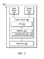
- FIG. 2 shows an alternative simplified functional block diagram of an electronic device 200 according to one embodiment of the present disclosure.
- the electronic device 200 can be utilized for realizing the management server 120 or the terminal device used by the driver.
- the electronic device 200 may include an input device 202 , an output device 204 , a control circuit 206 , a central processing unit (CPU) 208 , a memory 210 , a program code 212 , and a transceiver 214 .
- the control circuit 206 executes the program code 212 in the memory 210 through the CPU 208 , thereby controlling the operation of the wireless communications device 200 .
- the wireless communications device 200 can receive signals input by a user through the input device 202 , such as a keyboard or keypad, and can output images and sound through the output device 304 , such as a monitor or speakers.
- the transceiver 214 is used to receive and transmit wireless signals wirelessly, deliver received signals to the control circuit 206 , and output signals generated by the control circuit 206 .
- FIG. 3 is a flow diagram illustrating a method 300 for the vehicle entering or leaving a parking lot according to an embodiment of the present disclosure, wherein the method 300 may be used in the system 100 in FIG. 1 .
- step S 305 the system captures an image of a vehicle by using a first video camera.
- step S 310 the system determines whether the image satisfies a condition. When the system determines that the image satisfies the condition (“Yes” in step S 310 ), in step S 315 , a first barrier is raised. When the system determines that the image does not satisfy the condition (“No” in step S 310 ), in step S 330 , the system does not raise the first barrier to prevent the vehicle from entering or leaving the parking lot.
- the image in step S 305 may be an entrance image of the vehicle entering the parking lots, or an exit image of the vehicle approaching the first barrier.
- the condition is whether vehicle information of the vehicle in the entrance image matches information stored in a database.
- the system raises the first barrier.
- the image is the exit image of the vehicle approaching the first barrier
- the condition is whether the vehicle in the image enters within a third distance from the first barrier.
- the first barrier is raised.
- step S 320 the system detects whether there is only the one vehicle between the first barrier and the second barrier.
- the distance between the first barrier and the second barrier is within a range.
- the second barrier is raised so that the vehicle enters or leaves the parking lot.
- the system locks the first barrier and the second barrier, and the management server transmits a notification message to notify an administrator to deal with the situation.
- the locked first barrier and locked second barrier can only be manually unlocked by the administrator to increase safety.
- the system may further detect whether the vehicle has passed through the first barrier after raising the first barrier in step S 315 . When the system detects that the vehicle has passed through the first barrier, the system lowers the first barrier. In another embodiment, the system further detects whether the vehicle has passed through the second barrier after the system raises the second barrier in step S 325 . The system lowers the second barrier when detecting that the vehicle has passed through the second barrier.
- FIGS. 4A ⁇ 4 C are flow diagrams illustrating a method 400 for the vehicle entering a parking lot according to another embodiment of the present disclosure, wherein the method 400 may be used in the system 100 in FIG. 1 .
- step S 402 the system captures a first entrance image of a vehicle entering a parking lot by using a first video camera.
- step S 404 the system determines whether vehicle information of the vehicle matches information stored in a database according to the first entrance image, wherein the vehicle information may be a license number.
- the system determines that the vehicle information matches the information stored in the database (“Yes” in step S 404 )
- step S 406 the system raises a first entrance barrier.
- step S 408 the system does not raise the first entrance barrier so that the vehicle cannot enter the parking lot.
- step S 410 the system detects whether the vehicle has passed through the first entrance barrier.
- the system detects that the vehicle has passed through the first entrance barrier (“Yes” in step S 410 )
- the system lowers the first entrance barrier in step S 412 .
- the process returns to step S 410 and the system continues detecting whether the vehicle has passed through the first entrance barrier.
- step S 414 the system detects whether there is only the one vehicle between the first entrance barrier and the second entrance barrier.
- step S 416 the system raises the second entrance barrier.
- step S 418 the system locks the first barrier and the second barrier, and the management server transmits a notification message to notify an administrator to deal with the situation.
- the locked first barrier and locked second barrier can only be manually unlocked by the administrator to increase safety.
- step S 420 the system detects whether the vehicle has passed through the second entrance barrier.
- the system detects that the vehicle has passed through the second entrance barrier (“Yes” in step S 420 )
- the system lowers the second entrance barrier.
- the process returns to step S 420 and the system continues detecting whether the vehicle has passed the second entrance barrier.
- step S 424 the system may determine whether there is a fixed parking space in the database corresponding to the vehicle information.
- step S 426 the system transmits a first indication signal to indicate the fixed parking space.
- step S 428 the system can select a first parking space as the parking space of the vehicle and transmit the first indication signal to indicate the parking space, wherein the first parking space is selected from among the parking spaces in which the vehicle has previously parked in a history record corresponding to the vehicle in the database.
- the first parking space selected from the database is a parking space closest to the current position of the vehicle among the parking spaces in a history record corresponding to the vehicle.
- the system may also randomly select a first parking space as the parking space of the vehicle.
- the system may transmit a first indication signal to the terminal device of the driver to indicate the route and location of the fixed parking space.
- the system may also transmit the first indication signal to the parking lot light to control the parking lot light to emit light in different colors so that the driver can find the fixed parking space according to the parking lot light.
- step S 430 the system detects whether the vehicle enters within a first distance from the parking space.
- the system can detect that the vehicle has approached the parking space using the video camera.
- step S 432 the system raises a parking-space barrier corresponding to the parking space so that the vehicle can enter the parking space.
- the process returns to step S 430 and the system continues detecting whether the vehicle enters within the first distance from the parking space.
- step S 434 the system detects whether a wheel blocking structure corresponding to the parking space is triggered.
- step S 436 the system detects whether a person has left the parking space.
- step S 438 the system lowers the parking-space barrier.
- step S 434 When the system detects that the wheel blocking structure has not been triggered (“No” in step S 434 ), the process returns to step S 434 and the system continues detecting whether the wheel blocking structure is triggered. When the system has not detected that the person leaves the parking space (“No” in step S 436 ), the process returns to step S 436 and the system continues detecting whether there is a person leaving the parking space.
- step S 440 the system detects whether the person enters within a second distance from a personnel access door. In other words, using the video camera, the system can detect whether the person is close to the personnel access door.
- step S 442 the system opens the personnel access door to allow the person to leave the parking lot.
- the process returns to step S 440 and the system continues detecting whether the person enters within the second distance from the personnel access door.
- step S 444 the system detects whether the person has left the parking lot.
- step S 446 the system closes the personnel access door.
- the process returns to step S 444 and the system continues detecting whether the person has left the parking lot.
- FIGS. 5A ⁇ 5 C are flow diagrams illustrating a method 500 for the vehicle leaving a parking lot according to another embodiment of the present disclosure, wherein the method 500 may be used in the system 100 in FIG. 1 .
- step S 502 the system captures a second entrance image from a personnel access door by a second video camera, wherein the second entrance image has a person.
- step S 504 the system determines whether the face of the person matches the facial image of the person in the database.
- step S 506 the system opens the personnel access door so that the person can enter the parking lot.
- step S 508 the system does not open the personnel access door to prevent the person from entering the parking lot.
- step S 510 the system detects whether the person has passed through the personnel access door.
- step S 512 the system closes the personnel access door.
- the process returns to step S 510 and the system continues detecting whether the person has passed the personnel access door.
- the system may transmit a second indication signal to indicate parking spaces corresponding to the person.
- the system may send a second indication signal to the terminal device of the driver to indicate the route and the location of the parking space.
- the system may also send the second indication signal to the parking lot light to control the parking lot light to emit light in different colors so that the driver can find the parking space according to the parking lot light.
- step S 516 the system detects whether the person enters within a first distance from the parking space. In other words, the system can detect whether the person has approached the parking space using the video camera.
- step S 518 the system raises the parking-space barrier corresponding to the parking space so that the person can enter the parking space.
- the process returns to step S 516 and the system continues detecting whether the person enters within the first distance from the parking space.
- step S 520 the system detects whether the person has entered the vehicle.
- the system detects that the person has entered the vehicle (“Yes” in step S 520 )
- step S 522 the system lowers the parking-space barrier to prevent other people from entering the parking space.
- the process returns to step S 520 and the system continues detecting whether the person has entered the vehicle.
- step S 524 the system detects whether there is any other person showing up suddenly.
- step S 526 the system locks the parking-space barrier and the wheel blocking structure, and the management server sends a notification message to notify the administrator to deal with the situation.
- the locked parking-space barrier and locked wheel blocking structure can only be manually unlocked by the administrator to increase safety.
- step S 528 the system raises the parking-space barrier and restores the wheel blocking structure so that the vehicle can leave the parking space.
- step S 530 the system detects whether the vehicle has left the parking space.
- the system detects that the vehicle has left the parking space (“Yes” in step S 530 )
- step S 532 the system lowers the parking-space barrier to prevent other people from entering the parking space.
- the process returns to step S 530 and the system continues detecting whether the vehicle has left the parking space.
- the system may transmit a third indication signal to indicate the exit of the parking lot.
- the system may transmit the third indication signal to the terminal device of the driver to indicate the route and the location of the exit of the parking lot.
- the system may also transmit the third indication signal to the parking lot light to control the parking lot light to emit light in different colors so that the driver can find the exit of the parking lot according to the parking lot light.
- step S 536 the system detects whether the vehicle enters within a third distance from a first exit barrier. In other words, using the video camera, the system can detect whether the vehicle is approaching the vehicle.
- the system detects that the vehicle enters within the third distance from the first exit barrier (“Yes” in step S 536 )
- step S 538 the system raises the first exit barrier.
- the process returns to step S 536 and the system continues detecting whether the vehicle enters within the third distance from the first exit barrier.
- step S 540 the system detects whether the vehicle has passed through the first exit barrier.
- the system detects that the vehicle has passed through the first exit barrier (“Yes” in step S 540 )
- step S 542 the system lowers the first exit barrier.
- the process returns to step S 540 and the system continues detecting whether the vehicle has passed through the first exit barrier.
- step S 544 the system detects whether there is only the one vehicle between the first exit barrier and the second exit barrier.
- step S 546 the system raises the second exit barrier.
- step S 548 the system locks the first exit barrier and the second exit barrier, and the management server sends a notification message to notify the administrator to deal with the situation.
- the locked exit barrier and locked second exit barrier can only be manually unlocked by the administrator to increase safety.
- step S 550 the system detects whether the vehicle has passed through the second exit barrier.
- the system detects that the vehicle has passed through the second exit barrier (“Yes” in step S 550 )
- step S 552 the system lowers the second exit barrier.
- the process returns to step S 550 and the system continues detecting whether the vehicle has passed through the second exit barrier.
- FIGS. 6 ⁇ 7 are exploded views of the wheel blocking structure 180 according to an embodiment of the present disclosure.
- the wheel blocking structure 180 mainly includes a floor 610 , a bottom plate 620 , a left bracket 630 , a shaft 640 , a rotation blocking component 650 , and a locking assembly 60 .
- the exploded view of the locking assembly 60 is shown in FIG. 7 .
- the locking assembly 60 mainly includes a right bracket 660 , a motor 680 , an electromagnetic lock 690 , a torsion spring 702 , a screw 704 , a compression spring 706 and a movable component 708 .
- the floor 610 is used to accommodate other components to support the weight of the vehicle.
- the bottom plate 620 fixes the left bracket 630 and the right bracket 660 .
- the left bracket 630 is pivoted to the rotation blocking component 650 through the shaft 640
- the right bracket 660 is pivoted to the rotation blocking component 650 through the motor 680 .
- the wheel blocking structure 180 may have a sensing device (not shown), which may be connected to the management server 120 in FIG. 1 and may be controlled by the management server 120 .
- the torsion spring 702 is mounted on the axis center of the motor 680 and is restrained by the right bracket 660 to rotate the rotation blocking component 650 upward.
- the motor 680 is fixed on the right bracket 660 to rotate the rotation blocking member 650 .
- the screw 704 fixes the rotation blocking component 650 on the axis center of the motor 680 so that the motor 680 can drive the rotation blocking component 650 to rotate.
- the electromagnetic lock 690 is fixed on the right bracket 660 , and has a barbed portion 690 A and a connecting portion 690 B.
- the barbed portion 690 A can push the movable component 708 away through the compression spring 706 .
- the right bracket 660 has an opening portion 662 .
- FIGS. 8A ⁇ 8 D are schematic diagrams illustrating how the wheel and the wheel blocking structure 180 work together according to an embodiment of the present disclosure with reference to FIGS. 6 ⁇ 7 .
- the wheel 810 has not touched the wheel blocking structure 180 , so the wheel blocking structure 180 has not moved.
- the wheel 810 presses on the rotation blocking component 650 . Since the weight of the vehicle 810 is greater than the support force of the wheel blocking structure 180 , the wheel 810 forces the rotation blocking component 650 to rotate downward. At this time, the vehicle can continue moving back.
- FIG. 8C the wheel 810 has passed the rotation blocking component 650 .
- the rotation blocking component 650 can be rotated upward from the floor 610 to the initial position by the torsion spring to prevent the wheel from forcibly passing through the rotation blocking component 650 .
- the management server may control the motor to rotate the rotation blocking component 650 downward by the sensing device so that the vehicle can leave the parking space.
- FIGS. 9A ⁇ 9 E are schematic diagrams illustrating how the wheel blocking structure 180 is locked according to an embodiment of the present disclosure with reference to FIGS. 6 ⁇ 7 . It should be noted that once the wheel blocking structure is locked, for safety, the wheel blocking structure can only be unlocked manually and cannot be unlocked remotely by the management server.
- FIG. 9A the wheel blocking structure has not been moved, so that the barbed portion 690 A of the electromagnetic lock 690 is in the initial position.
- FIGS. 9B to 9C the barbed portion 690 A of the electromagnetic lock 690 moves along a direction D 1 (a negative Y-axis direction) and forces the movable component 708 to move toward the motor 680 along the direction D 1 .
- FIGS. 9D to 9E the movable component 708 contacts the connecting portion 690 B of the electromagnetic lock 690 , and the movable component 708 moves toward the electromagnetic lock 690 in a direction D 2 (a Y-axis direction) by the compression spring 706 and returns to the initial position to ensure that the electromagnetic lock 690 cannot return to its initial position.
- central processing unit 208 can execute the program code 212 in the memory to perform all of the above-described actions and steps or others described herein.
- the method and the system for managing the parking lot provided in the present disclosure can ensure the safety of people and vehicles from entering the parking lot to leaving the parking lot.
- the barriers and wheel blocking device provided in the present disclosure can only be manually unlocked after being locked, the safety of the people and vehicles can further be increased.
- the various illustrative logical blocks, modules, and circuits described in connection with the aspects disclosed herein may be implemented within or performed by an integrated circuit (“IC”), an access terminal, or an access point.
- the IC may comprise a general purpose processor, a digital signal processor (DSP), an application specific integrated circuit (ASIC), a field programmable gate array (FPGA) or another programmable logic device, discrete gate or transistor logic, discrete hardware components, electrical components, optical components, mechanical components, or any combination thereof designed to perform the functions described herein, and may execute codes or instructions that reside within the IC, outside of the IC, or both.
- a general purpose processor may be a microprocessor, but in the alternative, the processor may be any processor, controller, microcontroller, or state machine.
- a processor may also be implemented as a combination of computing devices, e.g., a combination of a DSP and a microprocessor, a plurality of microprocessors, one or more microprocessors in conjunction with a DSP core, or any other such configuration.
Landscapes
- Physics & Mathematics (AREA)
- General Physics & Mathematics (AREA)
- Engineering & Computer Science (AREA)
- Mechanical Engineering (AREA)
- Business, Economics & Management (AREA)
- Finance (AREA)
- Computer Security & Cryptography (AREA)
- Transportation (AREA)
- Human Computer Interaction (AREA)
- Traffic Control Systems (AREA)
- Devices For Checking Fares Or Tickets At Control Points (AREA)
Applications Claiming Priority (3)
| Application Number | Priority Date | Filing Date | Title |
|---|---|---|---|
| TW106131399A | 2017-09-13 | ||
| TW106131399 | 2017-09-13 | ||
| TW106131399A TWI637357B (zh) | 2017-09-13 | 2017-09-13 | 管理停車場的方法及系統 |
Publications (2)
| Publication Number | Publication Date |
|---|---|
| US20190080595A1 US20190080595A1 (en) | 2019-03-14 |
| US10339802B2 true US10339802B2 (en) | 2019-07-02 |
Family
ID=64797452
Family Applications (1)
| Application Number | Title | Priority Date | Filing Date |
|---|---|---|---|
| US15/863,838 Active US10339802B2 (en) | 2017-09-13 | 2018-01-05 | Method and system for managing a parking lot |
Country Status (3)
| Country | Link |
|---|---|
| US (1) | US10339802B2 (zh) |
| CN (1) | CN109493453B (zh) |
| TW (1) | TWI637357B (zh) |
Cited By (1)
| Publication number | Priority date | Publication date | Assignee | Title |
|---|---|---|---|---|
| EP4086124A3 (en) * | 2021-09-23 | 2023-03-22 | Apollo Intelligent Connectivity (Beijing) Technology Co., Ltd. | Vehicle security check method, system and apparatus, device and storage medium |
Families Citing this family (6)
| Publication number | Priority date | Publication date | Assignee | Title |
|---|---|---|---|---|
| CN113450576A (zh) * | 2019-02-25 | 2021-09-28 | 西安艾润物联网技术服务有限责任公司 | 机械车库管理方法、装置、系统及存储介质 |
| US11436836B2 (en) | 2019-06-28 | 2022-09-06 | Ricardo Ernesto Ramirez | Vehicular access security system |
| US11631329B2 (en) * | 2020-07-08 | 2023-04-18 | Honda Motor Co., Ltd | Venue location identification for vehicular access control |
| CN112258712A (zh) * | 2020-09-08 | 2021-01-22 | 福建云晟物联网科技有限公司 | 一种智能型非机动车停车场的门禁系统 |
| CN112489489A (zh) * | 2020-12-14 | 2021-03-12 | 四川易泊时捷智能科技有限公司 | 一种基于区块链的停车场管理方法 |
| CN114220275B (zh) * | 2022-02-22 | 2022-05-24 | 浙江创泰科技有限公司 | 一种无人值守智慧停车管理系统 |
Citations (6)
| Publication number | Priority date | Publication date | Assignee | Title |
|---|---|---|---|---|
| US20060232442A1 (en) * | 2003-01-30 | 2006-10-19 | Fredrik Vastad | Vehicle id |
| US20070069921A1 (en) * | 2004-05-21 | 2007-03-29 | Sefton Alan K | Automated site security, monitoring and access control system |
| US20130117078A1 (en) | 2000-08-24 | 2013-05-09 | Martin Herman Weik, III | Virtual attendant system and parking management system |
| TWM456561U (zh) | 2013-03-08 | 2013-07-01 | Parkinsys Technology Corp | 雙向單通道停車場用的停車場管理系統 |
| TWM464511U (zh) | 2013-04-17 | 2013-11-01 | Yua Yung Marketing Taiwan Co Ltd | 停車擋板裝置 |
| US20170073912A1 (en) * | 2015-09-11 | 2017-03-16 | Westfield Labs Corporation | Vehicle barrier system |
Family Cites Families (17)
| Publication number | Priority date | Publication date | Assignee | Title |
|---|---|---|---|---|
| EP2510740B1 (en) * | 2009-12-11 | 2019-09-11 | Stationnement Urbain Developpements et Etudes | Providing city services using mobile devices and a sensor network |
| KR101565226B1 (ko) * | 2012-09-12 | 2015-11-02 | 미츠비시 쥬고우 메카토로시스테무즈 가부시키가이샤 | 조작반 및 이것을 구비한 기계식 주차 설비 |
| CN102968873B (zh) * | 2012-11-29 | 2015-01-07 | 深圳市捷顺科技实业股份有限公司 | 一种停车场预警系统 |
| TWI536330B (zh) * | 2013-11-14 | 2016-06-01 | 動聯國際股份有限公司 | 停車管理系統與燈源裝置 |
| CN204087517U (zh) * | 2013-12-19 | 2015-01-07 | 深圳市捷顺科技实业股份有限公司 | 一种基于人脸识别技术的寻车系统 |
| CN103912178B (zh) * | 2014-04-15 | 2016-04-20 | 江苏绿建节能科技有限公司 | 一种自动开门闭门装置 |
| CN103985173B (zh) * | 2014-05-15 | 2017-01-11 | 兴天通讯技术(天津)有限公司 | 停车场管理系统 |
| CN103996231B (zh) * | 2014-05-30 | 2016-05-11 | 中国科学院宁波材料技术与工程研究所 | 一种车辆进出管控系统 |
| DE102014008283A1 (de) * | 2014-06-03 | 2015-12-03 | Man Truck & Bus Ag | Verfahren und Anordnung zur Warnung von Verkehrsteilnehmern, die ein stillstehendes Fahrzeug passieren |
| CN104282047A (zh) * | 2014-10-27 | 2015-01-14 | 合肥指南针电子科技有限责任公司 | 一种双道闸出口的停车场管理方法及系统 |
| CN104715512A (zh) * | 2015-04-01 | 2015-06-17 | 重庆蓝岸通讯技术有限公司 | 一种停车场自动收费系统 |
| TW201706955A (zh) * | 2015-08-07 | 2017-02-16 | 崑山科技大學 | 智慧型自動化立體停車場系統 |
| US11455838B2 (en) * | 2016-01-13 | 2022-09-27 | Parkhub, Inc. | System for monitoring arrival of a vehicle at a given location and associated methods |
| CN106683471A (zh) * | 2017-02-24 | 2017-05-17 | 武汉大思想信息股份有限公司 | 一种地下停车场停取车管理方法及系统 |
| JP6186529B1 (ja) * | 2017-03-24 | 2017-08-23 | 株式会社オーガスタス | 駐車場管理システムおよび駐車場管理方法 |
| CN107016852B (zh) * | 2017-04-25 | 2023-01-24 | 上海亦源智能科技有限公司 | 具有防胁迫的智能停车出入控制系统及方法 |
| CN107123273A (zh) * | 2017-06-15 | 2017-09-01 | 合肥讯邦网络科技有限公司 | 一种智能停车管理系统 |
-
2017
- 2017-09-13 TW TW106131399A patent/TWI637357B/zh active
- 2017-09-21 CN CN201710858541.1A patent/CN109493453B/zh active Active
-
2018
- 2018-01-05 US US15/863,838 patent/US10339802B2/en active Active
Patent Citations (6)
| Publication number | Priority date | Publication date | Assignee | Title |
|---|---|---|---|---|
| US20130117078A1 (en) | 2000-08-24 | 2013-05-09 | Martin Herman Weik, III | Virtual attendant system and parking management system |
| US20060232442A1 (en) * | 2003-01-30 | 2006-10-19 | Fredrik Vastad | Vehicle id |
| US20070069921A1 (en) * | 2004-05-21 | 2007-03-29 | Sefton Alan K | Automated site security, monitoring and access control system |
| TWM456561U (zh) | 2013-03-08 | 2013-07-01 | Parkinsys Technology Corp | 雙向單通道停車場用的停車場管理系統 |
| TWM464511U (zh) | 2013-04-17 | 2013-11-01 | Yua Yung Marketing Taiwan Co Ltd | 停車擋板裝置 |
| US20170073912A1 (en) * | 2015-09-11 | 2017-03-16 | Westfield Labs Corporation | Vehicle barrier system |
Cited By (1)
| Publication number | Priority date | Publication date | Assignee | Title |
|---|---|---|---|---|
| EP4086124A3 (en) * | 2021-09-23 | 2023-03-22 | Apollo Intelligent Connectivity (Beijing) Technology Co., Ltd. | Vehicle security check method, system and apparatus, device and storage medium |
Also Published As
| Publication number | Publication date |
|---|---|
| US20190080595A1 (en) | 2019-03-14 |
| TW201915954A (zh) | 2019-04-16 |
| CN109493453B (zh) | 2022-06-21 |
| CN109493453A (zh) | 2019-03-19 |
| TWI637357B (zh) | 2018-10-01 |
Similar Documents
| Publication | Publication Date | Title |
|---|---|---|
| US10339802B2 (en) | Method and system for managing a parking lot | |
| US11486185B2 (en) | Touch-free door apparatus, system and methods thereof | |
| US10654448B2 (en) | Vehicle security system | |
| US10145071B2 (en) | Vehicle barrier system | |
| US20180025141A1 (en) | Physical system access control | |
| KR100768820B1 (ko) | 차량 탑재하여 운행중 위법차량 단속장치 및 그 운용방법 | |
| US20100052947A1 (en) | Camera with built-in license plate recognition function | |
| JP7186818B2 (ja) | 情報処理装置、情報処理方法、プログラム、及び情報処理システム | |
| US20070069921A1 (en) | Automated site security, monitoring and access control system | |
| WO2014031563A2 (en) | System and method for neighborhood-scale vehicle monitoring | |
| CN109064611B (zh) | 一种社区通行控制方法及系统 | |
| CA2526551C (en) | Automated site security, monitoring and access control system | |
| CN103456057A (zh) | 一种基于车牌、人脸和指纹分级自动识别的门禁系统 | |
| WO2014138677A1 (en) | Predictive analysis using vehicle license plate recognition | |
| US11151828B2 (en) | Frictionless building access control system with tailgate detection | |
| US9741247B2 (en) | Parking monitoring system | |
| KR101636827B1 (ko) | 차량 번호 인식시스템 | |
| WO2018037392A1 (en) | System and method for access control in open restricted areas | |
| CN108025702B (zh) | 机动车的保障 | |
| KR102168297B1 (ko) | 딥러닝과 IoT 기반의 객체 출입 통제 장치 및 방법 | |
| CN104794784A (zh) | 一种远程解锁的停车场系统和方法 | |
| TWI663578B (zh) | 停車場管理系統與車輛進出管制方法 | |
| TWI737660B (zh) | 用以操作入口之控制系統的方法及用以控制入口之系統 | |
| EP3586317A1 (en) | Method and system for automatic passenger counting in public transport | |
| KR20140077651A (ko) | 주차 관리 시스템 및 방법 |
Legal Events
| Date | Code | Title | Description |
|---|---|---|---|
| FEPP | Fee payment procedure |
Free format text: ENTITY STATUS SET TO UNDISCOUNTED (ORIGINAL EVENT CODE: BIG.); ENTITY STATUS OF PATENT OWNER: LARGE ENTITY |
|
| AS | Assignment |
Owner name: WISTRON CORP., TAIWAN Free format text: ASSIGNMENT OF ASSIGNORS INTEREST;ASSIGNOR:LIANG, CHEN-YI;REEL/FRAME:044573/0212 Effective date: 20171226 |
|
| STPP | Information on status: patent application and granting procedure in general |
Free format text: RESPONSE AFTER FINAL ACTION FORWARDED TO EXAMINER |
|
| STPP | Information on status: patent application and granting procedure in general |
Free format text: NOTICE OF ALLOWANCE MAILED -- APPLICATION RECEIVED IN OFFICE OF PUBLICATIONS |
|
| STPP | Information on status: patent application and granting procedure in general |
Free format text: PUBLICATIONS -- ISSUE FEE PAYMENT VERIFIED |
|
| STCF | Information on status: patent grant |
Free format text: PATENTED CASE |
|
| MAFP | Maintenance fee payment |
Free format text: PAYMENT OF MAINTENANCE FEE, 4TH YEAR, LARGE ENTITY (ORIGINAL EVENT CODE: M1551); ENTITY STATUS OF PATENT OWNER: LARGE ENTITY Year of fee payment: 4 |