US10330337B2 - Outdoor unit - Google Patents
Outdoor unit Download PDFInfo
- Publication number
- US10330337B2 US10330337B2 US15/594,181 US201715594181A US10330337B2 US 10330337 B2 US10330337 B2 US 10330337B2 US 201715594181 A US201715594181 A US 201715594181A US 10330337 B2 US10330337 B2 US 10330337B2
- Authority
- US
- United States
- Prior art keywords
- communication unit
- data communication
- outside air
- unit
- outdoor
- Prior art date
- Legal status (The legal status is an assumption and is not a legal conclusion. Google has not performed a legal analysis and makes no representation as to the accuracy of the status listed.)
- Active
Links
- 238000004891 communication Methods 0.000 claims abstract description 91
- 238000009423 ventilation Methods 0.000 claims abstract description 51
- 238000005057 refrigeration Methods 0.000 claims description 12
- 230000005611 electricity Effects 0.000 claims description 3
- 230000005674 electromagnetic induction Effects 0.000 claims description 3
- 238000005516 engineering process Methods 0.000 claims description 3
- 230000002093 peripheral effect Effects 0.000 claims description 3
- 238000003745 diagnosis Methods 0.000 description 9
- 238000004378 air conditioning Methods 0.000 description 4
- 210000000078 claw Anatomy 0.000 description 4
- 238000000034 method Methods 0.000 description 4
- 239000000463 material Substances 0.000 description 3
- 230000008569 process Effects 0.000 description 3
- 125000006850 spacer group Chemical group 0.000 description 3
- XEEYBQQBJWHFJM-UHFFFAOYSA-N Iron Chemical compound [Fe] XEEYBQQBJWHFJM-UHFFFAOYSA-N 0.000 description 2
- 230000008901 benefit Effects 0.000 description 2
- 239000002184 metal Substances 0.000 description 2
- 229910052751 metal Inorganic materials 0.000 description 2
- 239000003507 refrigerant Substances 0.000 description 2
- 230000002159 abnormal effect Effects 0.000 description 1
- 230000009471 action Effects 0.000 description 1
- 238000005452 bending Methods 0.000 description 1
- 230000009286 beneficial effect Effects 0.000 description 1
- 238000010168 coupling process Methods 0.000 description 1
- 230000006870 function Effects 0.000 description 1
- 229910052742 iron Inorganic materials 0.000 description 1
- 239000000696 magnetic material Substances 0.000 description 1
- 238000012986 modification Methods 0.000 description 1
- 230000004048 modification Effects 0.000 description 1
- 238000006467 substitution reaction Methods 0.000 description 1
- 238000010792 warming Methods 0.000 description 1
- XLYOFNOQVPJJNP-UHFFFAOYSA-N water Substances O XLYOFNOQVPJJNP-UHFFFAOYSA-N 0.000 description 1
Images


Classifications
-
- H—ELECTRICITY
- H04—ELECTRIC COMMUNICATION TECHNIQUE
- H04B—TRANSMISSION
- H04B5/00—Near-field transmission systems, e.g. inductive or capacitive transmission systems
- H04B5/70—Near-field transmission systems, e.g. inductive or capacitive transmission systems specially adapted for specific purposes
- H04B5/79—Near-field transmission systems, e.g. inductive or capacitive transmission systems specially adapted for specific purposes for data transfer in combination with power transfer
-
- F—MECHANICAL ENGINEERING; LIGHTING; HEATING; WEAPONS; BLASTING
- F24—HEATING; RANGES; VENTILATING
- F24F—AIR-CONDITIONING; AIR-HUMIDIFICATION; VENTILATION; USE OF AIR CURRENTS FOR SCREENING
- F24F11/00—Control or safety arrangements
- F24F11/89—Arrangement or mounting of control or safety devices
-
- F—MECHANICAL ENGINEERING; LIGHTING; HEATING; WEAPONS; BLASTING
- F24—HEATING; RANGES; VENTILATING
- F24F—AIR-CONDITIONING; AIR-HUMIDIFICATION; VENTILATION; USE OF AIR CURRENTS FOR SCREENING
- F24F1/00—Room units for air-conditioning, e.g. separate or self-contained units or units receiving primary air from a central station
- F24F1/06—Separate outdoor units, e.g. outdoor unit to be linked to a separate room comprising a compressor and a heat exchanger
- F24F1/20—Electric components for separate outdoor units
- F24F1/22—Arrangement or mounting thereof
-
- F—MECHANICAL ENGINEERING; LIGHTING; HEATING; WEAPONS; BLASTING
- F24—HEATING; RANGES; VENTILATING
- F24F—AIR-CONDITIONING; AIR-HUMIDIFICATION; VENTILATION; USE OF AIR CURRENTS FOR SCREENING
- F24F11/00—Control or safety arrangements
- F24F11/30—Control or safety arrangements for purposes related to the operation of the system, e.g. for safety or monitoring
- F24F11/32—Responding to malfunctions or emergencies
- F24F11/38—Failure diagnosis
-
- F—MECHANICAL ENGINEERING; LIGHTING; HEATING; WEAPONS; BLASTING
- F24—HEATING; RANGES; VENTILATING
- F24F—AIR-CONDITIONING; AIR-HUMIDIFICATION; VENTILATION; USE OF AIR CURRENTS FOR SCREENING
- F24F11/00—Control or safety arrangements
- F24F11/50—Control or safety arrangements characterised by user interfaces or communication
-
- H04B5/0037—
-
- F—MECHANICAL ENGINEERING; LIGHTING; HEATING; WEAPONS; BLASTING
- F24—HEATING; RANGES; VENTILATING
- F24F—AIR-CONDITIONING; AIR-HUMIDIFICATION; VENTILATION; USE OF AIR CURRENTS FOR SCREENING
- F24F2110/00—Control inputs relating to air properties
-
- F—MECHANICAL ENGINEERING; LIGHTING; HEATING; WEAPONS; BLASTING
- F24—HEATING; RANGES; VENTILATING
- F24F—AIR-CONDITIONING; AIR-HUMIDIFICATION; VENTILATION; USE OF AIR CURRENTS FOR SCREENING
- F24F2110/00—Control inputs relating to air properties
- F24F2110/10—Temperature
- F24F2110/12—Temperature of the outside air
-
- H04B5/0031—
-
- H04B5/0075—
-
- H—ELECTRICITY
- H04—ELECTRIC COMMUNICATION TECHNIQUE
- H04B—TRANSMISSION
- H04B5/00—Near-field transmission systems, e.g. inductive or capacitive transmission systems
- H04B5/20—Near-field transmission systems, e.g. inductive or capacitive transmission systems characterised by the transmission technique; characterised by the transmission medium
- H04B5/24—Inductive coupling
-
- H—ELECTRICITY
- H04—ELECTRIC COMMUNICATION TECHNIQUE
- H04B—TRANSMISSION
- H04B5/00—Near-field transmission systems, e.g. inductive or capacitive transmission systems
- H04B5/70—Near-field transmission systems, e.g. inductive or capacitive transmission systems specially adapted for specific purposes
- H04B5/72—Near-field transmission systems, e.g. inductive or capacitive transmission systems specially adapted for specific purposes for local intradevice communication
Definitions
- Embodiments described herein relate generally to an outdoor unit for a refrigeration cycle apparatus such as an air conditioning apparatus.
- a transmitter-receiver having a function of near-field communication (NFC) is provided in the outdoor unit of a refrigeration cycle apparatus such as an air conditioning apparatus.
- NFC near-field communication
- Contactless data communication is performed between the transmitter-receiver and an information terminal to set various types of data necessary to operate the outdoor unit and diagnose the state of the outdoor unit.
- the transmitter-receiver operates with the electricity generated by electromagnetic induction due to radio waves transmitted from the information terminal.
- the housing of the outdoor unit is formed of a metal plate, which is a magnetic material.
- a metal plate which is a magnetic material.
- an opening is formed in the housing of the outdoor unit, and the transmitter-receiver is provided in the opening.
- An openable and closable cover is attached to the opening to shield the transmitter-receiver from wind and rain.
- Embodiments described herein aim to provide an outdoor unit which allows easy and steady data communication with an information terminal without any operation for opening or closing a cover.
- FIG. 1 is a perspective illustration showing an external appearance according to an embodiment.
- FIG. 2 is an enlarged view of a relevant part of FIG. 1 .
- FIG. 3 is a perspective illustration showing the structure of a communication unit according to the embodiment.
- FIG. 4 shows the procedure for attaching the communication unit according to the embodiment.
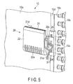
- FIG. 5 shows a state in which the communication unit is attached to an outdoor heat exchanger according to the embodiment.
- an outdoor unit comprises a housing, an outdoor heat exchanger and a communication unit.
- the housing comprises a ventilation opening and houses the outdoor heat exchanger.
- the communication unit is provided in the housing at a position facing the ventilation opening and performs contactless data communication with a nearby information terminal.
- the outline of an outdoor unit 1 is formed by a cubic housing 2 .
- the housing 2 includes front plates 3 and 4 , a right side plate 5 , top plates 6 and 7 , a left side plate, a rear plate, and a bottom plate.
- Front plates 3 and 4 , the right side plate 5 , the left side plate, the rear plate and the bottom plate are formed of metal, excluding top plates 6 and 7 .
- Front plate 3 is divided into an upper front plate 3 A and a lower front plate 3 B in a vertical direction. Each of upper and lower front plates 3 A and 3 B is removable.
- Upper front plate 3 A comprises a large number of rectangular ventilation openings (inlets) 3 a which are vertically and horizontally arranged.
- Front plate 4 is divided into an upper front plate 4 A and a lower front plate 4 B in a vertical direction in a manner similar to that of front plate 3 .
- Each of upper and lower front plates 4 A and 4 B is removable.
- Upper front plate 4 A comprises a large number of rectangular ventilation openings (inlets) 4 a arranged in a vertical direction.
- the right side plate 5 comprises a large number of rectangular ventilation openings (inlets) 5 a which are vertically and horizontally arranged.
- the left side plate comprises a large number of ventilation openings (inlets) which are vertically and horizontally arranged in a manner similar to that of the right side plate 5 .
- Each of top plates 6 and 7 comprises a circular ventilation opening.
- Cylindrical fan housings 8 and 9 are formed so as to cover the ventilation openings of top plates 6 and 7 , respectively.
- the inside of the housing 2 is divided into an upper heat exchange chamber 2 A and a lower machinery chamber 2 B by an intermediate divider 2 x .
- the heat exchange chamber 2 A is closed by upper front plates 3 A and 4 A.
- the machinery chamber 2 B is closed by lower front plates 3 B and 4 B.
- An outdoor heat exchanger 10 and outdoor fans 11 and 12 are housed in the heat exchange chamber 2 A.
- the outdoor heat exchanger 10 has a U-shape as seen in plan view.
- the outdoor heat exchanger 10 is placed on the intermediate divider 2 x along the left side plate, upper front plates 3 A and 4 A and the right side plate 5 of the housing 2 such that the outdoor heat exchanger 10 is close to these plates.
- the internal space of the outdoor heat exchanger 10 communicates with fan housings 8 and 9 via the ventilation openings of top plates 6 and 7 , respectively.
- Outdoor fans 11 and 12 are provided at positions corresponding to fan housings 8 and 9 .
- Refrigeration cycle constituting components 40 and an electrical component box 50 are housed in the machinery chamber 2 B.
- the refrigeration cycle constituting components 40 collectively mean a compressor, a four-way valve, a receiver tank, an accumulator, etc.
- the electrical component box 50 houses a plurality of drive circuits which drive the compressor, outdoor fans 11 and 12 , etc., and a main control unit (circuit board) 60 .
- the main control unit 60 controls the operation of the refrigeration cycle constituting components 40 and the drive circuits, sets data necessary to operate the outdoor unit 1 based on mutual data communication between a communication unit 20 and an information terminal 100 as described later, and diagnoses the state of the outdoor unit 1 .
- the internal components of the machinery chamber 2 B are exchanged or fixed by removing lower front plates 3 B and 4 B.
- outdoor fans 11 and 12 rotate, external air is drawn into the heat exchange chamber 2 A through the ventilation openings of the left side plate, ventilation openings 3 a and 4 a of upper front plates 3 B and 4 B and ventilation openings 5 a of the right side plate 5 .
- the drawn air passes through the outdoor heat exchanger 10 , and further goes through outdoor fans 11 and 12 and fan housings 8 and 9 . Subsequently, the air is discharged to the outside of the housing 2 .
- the air passing through the outdoor heat exchanger 10 exchanges heat with a refrigerant flowing through the outdoor heat exchanger 10 .
- the communication unit 20 is provided at a position corresponding to, of ventilation openings 4 a of upper front plate 4 A, for example, the second ventilation opening 4 a from the top, between upper front plate 4 A of the housing 2 and the outdoor heat exchanger 10 .
- the height position of the second ventilation opening 4 a from the top is substantially equivalent to the eye level of a worker standing next to the housing 2 .
- the outer circumference of the communication unit 20 is formed by a base portion 21 and a cover portion 22 pivotably supported in the upper edge of the base portion 21 such that the cover portion 22 is openable and closable.
- the base portion 21 is formed of a nonmagnetic material such as plastic, and is rectangular.
- the cover portion 22 is formed of a nonmagnetic material such as plastic, and is rectangular.
- the base portion 21 comprises a rectangular board-holding portion (a first holding portion) 21 x formed from the upper region to the middle region, a concave sensor-holding portion (a second holding portion) 21 y formed in the lower region, and a frame member 21 z formed along the peripheral border of the board-holding portion 21 x .
- a data communication unit (circuit board) 31 having the shape of a rectangular plate is held by the board-holding portion 21 x such that the data communication unit 31 fits in the board-holding portion 21 x .
- a large number of ventilation openings (first ventilation openings) 21 a having a cut shape in a vertical direction are arranged in a horizontal direction in the sensor-holding portion 21 y .
- a tubular outside air temperature sensor 32 is provided in the sensor-holding portion 21 y sideways.
- the outside air temperature sensor 32 is held by a pair of elastic hooks 21 b such that the outside air temperature sensor 32 is caught by hooks 21 b .
- the frame member 21 z prevents intrusion of rainwater into the board-holding portion 21 x.
- the data communication unit 31 is structured by providing an antenna 31 a , a transmitter-receiver 31 b , a CPU 31 c , a memory 31 d , a communication circuit 31 e , etc., on a board.
- the data communication unit 31 operates with the electricity generated by electromagnetic induction due to radio waves transmitted from the information terminal 100 , and performs contactless data communication with the information terminal 100 , using the near-field communication (NFC) technology.
- NFC near-field communication
- the antenna 31 a transmits or receives radio waves to/from the nearby information terminal 100 .
- the transmitter-receiver 31 b transmits or receives a signal through the antenna 31 a , and loads the radio waves received in the antenna 31 a as the operation power of the data communication unit 31 .
- the CPU 31 c performs various processes for data communication.
- the memory 31 d stores a program necessary to control the CPU 31 c , and temporarily stores received data and transmitted data.
- the communication circuit 31 e performs data communication between the transmitter-receiver 31 b and the main control unit 60 via a signal line 31 f.
- the outside air temperature sensor 32 detects outside air temperature.
- a signal line 32 a of the outside air temperature sensor 32 extends to the outside of the base portion 21 via a groove portion 21 c formed in the right side edge of the base portion 21 together with signal line 31 f of the data communication unit 31 .
- Signal lines 31 f and 32 a extending from the groove portion 21 c are guided to the machinery chamber 2 B along a refrigerant pipe connecting the outdoor heat exchanger 10 of the heat exchange chamber 2 A and the refrigeration cycle constituting components 40 of the machinery chamber 2 B, and are connected to the main control unit 60 of the machinery chamber 2 B. Since signal lines 31 f and 32 a can be collectively extended to the main control unit 60 , the wiring work can be simplified.
- the communication unit 20 comprises a plate-like portion 23 laterally extending from the right side edge of the base portion 21 , and an attachment portion 24 vertically extending from the plate-like portion 23 in a plate-like form.
- the plate-like portion 23 and the attachment portion 24 are formed of a nonmagnetic material such as plastic.
- the plate-like portion 23 comprises a pair of holding members 23 a for holding signal lines 31 f and 32 a extending from the groove portion 21 c such that both signal line 31 f and signal line 32 a are interposed between the holding members 23 a .
- the attachment portion 24 comprises a bent piece 24 a formed by bending the attachment portion 24 in an L-shape to the outdoor heat exchanger 10 side in the right side edge, and a pair of hooks 24 b in the upper and lower parts.
- the cover portion 22 covers the entire area of the internal side of the base portion 21 including the data communication unit 31 and the outside air temperature sensor 32 from above.
- a large number of ventilation openings (second ventilation openings) 22 a having a cut shape in a vertical direction are arranged in a horizontal direction in the lower region of the cover portion 22 . Ventilation openings 22 a face the sensor-holding portion 21 y of the base portion 21 when the cover portion 22 is closed.
- the cover portion 22 comprises an engagement claw 22 b in the lower edge, and a signal line cover 22 c in the right side edge. When the cover portion 22 is closed, the engagement claw 22 b engages with the lower edge of the base portion 21 and keeps the closed state of the cover portion 22 .
- the signal line cover 22 c covers the groove portion 21 c of the base portion 21 and signal lines 31 f and 32 a provided in the groove portion 21 c , and partially covers signal lines 31 f and 32 a extending from the groove portion 21 c.
- FIG. 4 and FIG. 5 the communication unit 20 in which the cover portion 22 is closed is removably attached to a predetermined position of the outdoor heat exchanger 10 .
- FIG. 4 and FIG. 5 partially show a front portion 10 a and a right side portion 10 b of the outdoor heat exchanger 10 .
- the front portion 10 a of the outdoor heat exchanger 10 faces upper front plates 3 A and 4 A of the housing 2 .
- the right side portion 10 b of the outdoor heat exchanger 10 faces the right side plate 5 of the housing 2 .
- a large number of heat exchange pipes 10 c provided in the outdoor heat exchanger 10 are exposed from the right side portion 10 b .
- a plate-like member 10 d is attached along the right edge portion of the front portion 10 a of the outdoor heat exchanger 10 .
- the plate-like member 10 d is formed of, for example, iron, and comprises a pair of engagement holes 10 e having an inverted-L-shape at predetermined positions in a vertical direction.
- the pair of hooks 24 b of the attachment portion 24 of the communication unit 20 is inserted into the engagement holes 10 e of the outdoor heat exchanger 10 .
- the inserted hooks 24 b engage with the lower edges of the engagement holes 10 e when hooks 24 b move downward along the shape of the engagement holes 10 e .
- the attachment portion 24 makes surface contact with the plate-like member 10 d .
- the bend piece 24 a of the attachment portion 24 makes surface contact with the right side portion 10 b of the outdoor heat exchanger 10 .
- the entire area of the cover portion 22 of the communication unit 20 faces the second ventilation opening 4 a of upper front plate 4 A of the housing 2 from the top.
- the height position of the second ventilation opening 4 a from the top is substantially equivalent to the eye level of a worker standing next to the housing 2 .
- a projecting spacer 21 d is formed on the rear surface of the base portion 21 .
- the distal end of the spacer 21 d is directly in contact with the front portion 10 a of the outdoor heat exchanger 10 after the completion of the attachment of the communication unit 20 .
- an appropriate distance is secured between the cover portion 22 of the communication unit 20 and upper front plate 4 A.
- the appropriate distance means that the cover portion 22 is as close to ventilation openings 4 a as possible without making contact with upper front plate 4 A.
- the cover portion 22 does not protrude from upper front plate 4 A through ventilation opening 4 a.
- the communication unit 20 should be merely lifted upward and pulled. By this action, hooks 24 b of the attachment portion 24 can be easily removed from the engagement holes 10 e . In this way, the removal of the communication unit 20 is completed.
- the main control unit 60 performs a data setting process and a diagnosis process for the outdoor unit 1 based on data communication with the information terminal 100 via the communication unit 20 .
- the information terminal 100 for example, a tablet information terminal or a smartphone information terminal is used.
- the content of data setting for example, various parameters related to the operation of the outdoor unit 1 are set, and a control program is updated.
- the content of diagnosis for example, the operation history or the failure of the outdoor unit 1 is confirmed.
- the radio waves emitted from the information terminal 100 are not disturbed by magnetic upper front plate 4 A and effectively reach the communication unit 20 through ventilation openings 4 a .
- the radio waves emitted from the communication unit 20 are not disturbed by magnetic upper front plate 4 A and effectively reach the information terminal 100 through ventilation openings 4 a.
- the base portion 21 and the cover portion 22 forming the outer circumference of the communication unit 20 are nonmagnetic members.
- the radio waves emitted from the information terminal 100 can be effectively loaded into the data communication unit 31 .
- the ratio waves emitted from the data communication unit 31 can be effectively transmitted to the information terminal 100 .
- a worker merely has to hold the information terminal 100 close to ventilation opening 4 a and operate the information terminal 100 . There is no need to remove upper front plate 4 A and attach it again. Thus, no complicated work is required. In this way, the workload of the worker can be reduced, and the working time can be reduced.
- the frame member 21 z is formed along the peripheral border of the board-holding portion 21 x of the base portion 21 .
- ventilation openings 21 a and 22 a for the ventilation of outside air are formed in the lower regions of the base portion 21 and the cover portion 22 , respectively.
- a worker can perform data setting or diagnosis for the outdoor unit 1 by putting up an umbrella with a hand and operating the information terminal 100 with the other hand.
- the outside air temperature sensor 32 Since the outside air temperature sensor 32 is held inside the communication unit 20 , there is no need to prepare a special holder for the outside air temperature sensor 32 . As such a holder is unnecessary, the cost can be reduced. Moreover, the base portion 21 and the cover portion 22 of the communication unit 20 comprise ventilation openings 21 a and 22 a , respectively. Thus, outside air can be directly drawn into the outside air temperature sensor 32 . Even in the structure comprising the outside air temperature sensor 32 housed in the communication unit 20 , the outside air temperature can be accurately detected.
- the communication unit 20 is provided at a position corresponding to the second ventilation opening 4 a of upper front plate 4 A from the top.
- the height position is not limited to this example, and can be appropriately determined.
- the communication unit 20 may be provided at a position corresponding to a lower ventilation opening 4 a as the internal side is difficult to see as a matter of course.
- an outdoor unit for an air conditioning apparatus as an outdoor unit for a refrigeration cycle apparatus.
- the embodiment is not limited to an outdoor unit for an air conditioning apparatus.
- the embodiment may be applied to, for example, an air-cooled chilling unit, a heat source unit for a heat-pump water heater, a heat source unit for a heat-pump warming device, and a refrigerator connected to a refrigerated showcase.
Landscapes
- Engineering & Computer Science (AREA)
- General Engineering & Computer Science (AREA)
- Chemical & Material Sciences (AREA)
- Combustion & Propulsion (AREA)
- Mechanical Engineering (AREA)
- Health & Medical Sciences (AREA)
- Human Computer Interaction (AREA)
- Biomedical Technology (AREA)
- Computer Networks & Wireless Communication (AREA)
- Signal Processing (AREA)
- Air Conditioning Control Device (AREA)
- Cooling Or The Like Of Electrical Apparatus (AREA)
- Transmitters (AREA)
- Selective Calling Equipment (AREA)
- Other Air-Conditioning Systems (AREA)
Applications Claiming Priority (3)
| Application Number | Priority Date | Filing Date | Title |
|---|---|---|---|
| JP2014233836 | 2014-11-18 | ||
| JP2014-233836 | 2014-11-18 | ||
| PCT/JP2015/082134 WO2016080352A1 (ja) | 2014-11-18 | 2015-11-16 | 室外機 |
Related Parent Applications (1)
| Application Number | Title | Priority Date | Filing Date |
|---|---|---|---|
| PCT/JP2015/082134 Continuation WO2016080352A1 (ja) | 2014-11-18 | 2015-11-16 | 室外機 |
Publications (2)
| Publication Number | Publication Date |
|---|---|
| US20170248329A1 US20170248329A1 (en) | 2017-08-31 |
| US10330337B2 true US10330337B2 (en) | 2019-06-25 |
Family
ID=56013889
Family Applications (1)
| Application Number | Title | Priority Date | Filing Date |
|---|---|---|---|
| US15/594,181 Active US10330337B2 (en) | 2014-11-18 | 2017-05-12 | Outdoor unit |
Country Status (6)
| Country | Link |
|---|---|
| US (1) | US10330337B2 (pt) |
| EP (1) | EP3222925B1 (pt) |
| JP (1) | JP6364501B2 (pt) |
| CN (1) | CN107110542B (pt) |
| BR (1) | BR112017010501B1 (pt) |
| WO (1) | WO2016080352A1 (pt) |
Cited By (1)
| Publication number | Priority date | Publication date | Assignee | Title |
|---|---|---|---|---|
| US20190160412A1 (en) * | 2017-11-27 | 2019-05-30 | Panasonic Ecology Systems Guandong Co., Ltd. | Ventilating device |
Families Citing this family (5)
| Publication number | Priority date | Publication date | Assignee | Title |
|---|---|---|---|---|
| WO2018016039A1 (ja) * | 2016-07-20 | 2018-01-25 | 三菱電機株式会社 | 空気調和システム |
| CN109564013B (zh) * | 2016-07-25 | 2021-09-03 | 三菱电机株式会社 | 空调机的室外机 |
| JP6721008B2 (ja) | 2018-07-12 | 2020-07-08 | ダイキン工業株式会社 | 空調機の通信システム及び空調機 |
| CN115940998A (zh) * | 2021-10-05 | 2023-04-07 | 开利公司 | 用于hvac设备的备选近场通信系统 |
| JP7485774B2 (ja) | 2022-04-28 | 2024-05-16 | 日立ジョンソンコントロールズ空調株式会社 | 空気調和機の室外機 |
Citations (29)
| Publication number | Priority date | Publication date | Assignee | Title |
|---|---|---|---|---|
| JPH10111001A (ja) | 1996-10-04 | 1998-04-28 | Mitsubishi Electric Corp | 特殊モード付き制御装置 |
| US6293697B1 (en) * | 2000-01-18 | 2001-09-25 | Mamac Systems, Inc. | Housing for HVAC control unit |
| JP2003148790A (ja) | 2001-11-12 | 2003-05-21 | Daikin Ind Ltd | 空気調和機 |
| US20040024846A1 (en) | 2000-08-22 | 2004-02-05 | Stephen Randall | Method of enabling a wireless information device to access data services |
| JP2005195209A (ja) | 2004-01-05 | 2005-07-21 | Daikin Ind Ltd | 室外ユニットの故障診断装置、室外ユニットの電装品ユニット及びそれを備えた室外ユニット |
| JP2006132870A (ja) | 2004-11-08 | 2006-05-25 | Fujitsu General Ltd | 空気調和機のメンテナンスシステム |
| JP2006165627A (ja) | 2004-12-02 | 2006-06-22 | Sharp Corp | 電気機器の遠隔監視システム |
| JP2006200874A (ja) * | 2004-12-24 | 2006-08-03 | Toshiba Kyaria Kk | 空気調和装置の室外機 |
| JP2007040584A (ja) | 2005-08-02 | 2007-02-15 | Hitachi Ltd | 空調システム、空調管理装置、室内機、読取装置、設定登録方法及び設定登録プログラム |
| JP2007322086A (ja) | 2006-06-02 | 2007-12-13 | Hitachi Appliances Inc | 空気調和機及び空気調和機の室内機 |
| JP2008101867A (ja) | 2006-10-20 | 2008-05-01 | Daikin Ind Ltd | 空調ユニット |
| JP2008281231A (ja) | 2007-05-08 | 2008-11-20 | Sharp Corp | 電気機器、空気調和機、室外機及び室内機 |
| JP2009237237A (ja) * | 2008-03-27 | 2009-10-15 | Brother Ind Ltd | プロジェクタ |
| US20100226104A1 (en) | 2006-02-01 | 2010-09-09 | Daikin Industries, Ltd. | Electrical equipment assembly and outdoor unit of air conditioner disposed with the electrical equipment assembly |
| US20100292960A1 (en) | 2009-05-15 | 2010-11-18 | Dongwon Sung | Method of diagnosing air conditioner and mobile terminal equipment for performing method |
| US20100292864A1 (en) | 2009-05-15 | 2010-11-18 | Dongwon Sung | Air conditioner and method of controlling the same |
| JP2012089910A (ja) | 2010-10-15 | 2012-05-10 | Panasonic Corp | エアコン装置 |
| US8322151B1 (en) * | 2008-08-13 | 2012-12-04 | Demand Side Environmental, LLC | Systems and methods for gathering data from and diagnosing the status of an air conditioner |
| JP5197549B2 (ja) | 2009-11-06 | 2013-05-15 | 三菱電機株式会社 | 設定診断システム |
| JP2013093766A (ja) | 2011-10-26 | 2013-05-16 | Tokai Rika Co Ltd | 双方向通信システム |
| JP2013120035A (ja) | 2011-12-08 | 2013-06-17 | Fujitsu General Ltd | 空気調和機 |
| US20130161403A1 (en) * | 2011-12-21 | 2013-06-27 | Lennox Industries Inc. | Hvac system, a controller therefor and a method of measuring and managing ventilation airflow of an hvac system |
| US20130231047A1 (en) | 2012-03-05 | 2013-09-05 | Canon Kabushiki Kaisha | Communication apparatus and control method thereof |
| JP2013218559A (ja) | 2012-04-10 | 2013-10-24 | Mitsubishi Electric Corp | 空調機管理装置、空調機管理プログラム、及び空調機管理システム |
| US20130297081A1 (en) | 2011-01-20 | 2013-11-07 | Fujitsu General Limited | Air conditioner |
| JP2014055739A (ja) | 2012-09-13 | 2014-03-27 | Toshiba Corp | 空気調和機用通信アダプタ |
| US20150051739A1 (en) * | 2013-07-22 | 2015-02-19 | Lg Electronics Inc. | Air conditioner system and method of controlling an air conditioner system |
| US20150362928A1 (en) * | 2013-02-28 | 2015-12-17 | Belimo Holding Ag | Control device, components, and mobile service device for an hvac system |
| US20170248336A1 (en) | 2014-11-19 | 2017-08-31 | Toshiba Carrier Corporation | Outdoor unit |
Family Cites Families (2)
| Publication number | Priority date | Publication date | Assignee | Title |
|---|---|---|---|---|
| JP4315835B2 (ja) * | 2004-02-20 | 2009-08-19 | 東芝キヤリア株式会社 | 空気調和機の室外ユニット |
| CN1928445B (zh) * | 2005-09-05 | 2010-10-13 | 珠海格力电器股份有限公司 | 多联空调机组及其网络通讯方法 |
-
2015
- 2015-11-16 CN CN201580062384.2A patent/CN107110542B/zh active Active
- 2015-11-16 WO PCT/JP2015/082134 patent/WO2016080352A1/ja active Application Filing
- 2015-11-16 BR BR112017010501-2A patent/BR112017010501B1/pt active IP Right Grant
- 2015-11-16 EP EP15860145.0A patent/EP3222925B1/en active Active
- 2015-11-16 JP JP2016560211A patent/JP6364501B2/ja active Active
-
2017
- 2017-05-12 US US15/594,181 patent/US10330337B2/en active Active
Patent Citations (31)
| Publication number | Priority date | Publication date | Assignee | Title |
|---|---|---|---|---|
| JPH10111001A (ja) | 1996-10-04 | 1998-04-28 | Mitsubishi Electric Corp | 特殊モード付き制御装置 |
| US6293697B1 (en) * | 2000-01-18 | 2001-09-25 | Mamac Systems, Inc. | Housing for HVAC control unit |
| US20040024846A1 (en) | 2000-08-22 | 2004-02-05 | Stephen Randall | Method of enabling a wireless information device to access data services |
| JP2003148790A (ja) | 2001-11-12 | 2003-05-21 | Daikin Ind Ltd | 空気調和機 |
| JP2005195209A (ja) | 2004-01-05 | 2005-07-21 | Daikin Ind Ltd | 室外ユニットの故障診断装置、室外ユニットの電装品ユニット及びそれを備えた室外ユニット |
| JP2006132870A (ja) | 2004-11-08 | 2006-05-25 | Fujitsu General Ltd | 空気調和機のメンテナンスシステム |
| JP2006165627A (ja) | 2004-12-02 | 2006-06-22 | Sharp Corp | 電気機器の遠隔監視システム |
| JP2006200874A (ja) * | 2004-12-24 | 2006-08-03 | Toshiba Kyaria Kk | 空気調和装置の室外機 |
| JP2007040584A (ja) | 2005-08-02 | 2007-02-15 | Hitachi Ltd | 空調システム、空調管理装置、室内機、読取装置、設定登録方法及び設定登録プログラム |
| US20100226104A1 (en) | 2006-02-01 | 2010-09-09 | Daikin Industries, Ltd. | Electrical equipment assembly and outdoor unit of air conditioner disposed with the electrical equipment assembly |
| JP2007322086A (ja) | 2006-06-02 | 2007-12-13 | Hitachi Appliances Inc | 空気調和機及び空気調和機の室内機 |
| JP2008101867A (ja) | 2006-10-20 | 2008-05-01 | Daikin Ind Ltd | 空調ユニット |
| JP2008281231A (ja) | 2007-05-08 | 2008-11-20 | Sharp Corp | 電気機器、空気調和機、室外機及び室内機 |
| JP2009237237A (ja) * | 2008-03-27 | 2009-10-15 | Brother Ind Ltd | プロジェクタ |
| US8322151B1 (en) * | 2008-08-13 | 2012-12-04 | Demand Side Environmental, LLC | Systems and methods for gathering data from and diagnosing the status of an air conditioner |
| US20100292960A1 (en) | 2009-05-15 | 2010-11-18 | Dongwon Sung | Method of diagnosing air conditioner and mobile terminal equipment for performing method |
| EP2253894A2 (en) | 2009-05-15 | 2010-11-24 | LG Electronics, Inc. | Air conditioner and method of controlling the same |
| US20100292864A1 (en) | 2009-05-15 | 2010-11-18 | Dongwon Sung | Air conditioner and method of controlling the same |
| JP5197549B2 (ja) | 2009-11-06 | 2013-05-15 | 三菱電機株式会社 | 設定診断システム |
| JP2012089910A (ja) | 2010-10-15 | 2012-05-10 | Panasonic Corp | エアコン装置 |
| US20130297081A1 (en) | 2011-01-20 | 2013-11-07 | Fujitsu General Limited | Air conditioner |
| EP2667110A1 (en) | 2011-01-20 | 2013-11-27 | Fujitsu General Limited | Air conditioner |
| JP2013093766A (ja) | 2011-10-26 | 2013-05-16 | Tokai Rika Co Ltd | 双方向通信システム |
| JP2013120035A (ja) | 2011-12-08 | 2013-06-17 | Fujitsu General Ltd | 空気調和機 |
| US20130161403A1 (en) * | 2011-12-21 | 2013-06-27 | Lennox Industries Inc. | Hvac system, a controller therefor and a method of measuring and managing ventilation airflow of an hvac system |
| US20130231047A1 (en) | 2012-03-05 | 2013-09-05 | Canon Kabushiki Kaisha | Communication apparatus and control method thereof |
| JP2013218559A (ja) | 2012-04-10 | 2013-10-24 | Mitsubishi Electric Corp | 空調機管理装置、空調機管理プログラム、及び空調機管理システム |
| JP2014055739A (ja) | 2012-09-13 | 2014-03-27 | Toshiba Corp | 空気調和機用通信アダプタ |
| US20150362928A1 (en) * | 2013-02-28 | 2015-12-17 | Belimo Holding Ag | Control device, components, and mobile service device for an hvac system |
| US20150051739A1 (en) * | 2013-07-22 | 2015-02-19 | Lg Electronics Inc. | Air conditioner system and method of controlling an air conditioner system |
| US20170248336A1 (en) | 2014-11-19 | 2017-08-31 | Toshiba Carrier Corporation | Outdoor unit |
Non-Patent Citations (6)
| Title |
|---|
| Aug. 13, 2018 extended European search report in connection with corresponding Europan patent application No. 15860145.0. |
| Feb. 2, 2016 ISR (and English translation thereof) and Written Opinion of the International Searching Authority in connection with PCT/JP2015/082135. |
| International Search Report and Written Opinion of the International Searching Authority in connection with PCT International Application No. PCT/JP2015/082134 including English language translation of the International Search Report. |
| Jan. 23, 2019 Amendment in Response dated Oct. 26, 2018 non-final Office Action in connection with commonly-owned U.S. Appl. No. 15/594,161. |
| Jun. 18, 2018 Extended European Search Report issued by the European Patent Office in connection with European Patent Application No. 15 861 507.0. |
| Oct. 26, 2018 non-final Office Action in connection with commonly-owned U.S. Appl. No. 15/594,161. |
Cited By (2)
| Publication number | Priority date | Publication date | Assignee | Title |
|---|---|---|---|---|
| US20190160412A1 (en) * | 2017-11-27 | 2019-05-30 | Panasonic Ecology Systems Guandong Co., Ltd. | Ventilating device |
| US11077396B2 (en) * | 2017-11-27 | 2021-08-03 | Panasonic Ecology Systems Guangdong Co., Ltd. | Ventilating device |
Also Published As
| Publication number | Publication date |
|---|---|
| WO2016080352A1 (ja) | 2016-05-26 |
| US20170248329A1 (en) | 2017-08-31 |
| EP3222925A4 (en) | 2018-09-12 |
| EP3222925A1 (en) | 2017-09-27 |
| CN107110542A (zh) | 2017-08-29 |
| JP6364501B2 (ja) | 2018-07-25 |
| BR112017010501A2 (pt) | 2018-04-03 |
| CN107110542B (zh) | 2021-11-30 |
| JPWO2016080352A1 (ja) | 2017-07-13 |
| EP3222925B1 (en) | 2020-09-30 |
| BR112017010501B1 (pt) | 2022-12-27 |
| BR112017010501A8 (pt) | 2022-09-27 |
Similar Documents
| Publication | Publication Date | Title |
|---|---|---|
| US10330337B2 (en) | Outdoor unit | |
| JP6417476B2 (ja) | 室外機 | |
| JP6613349B2 (ja) | 冷凍サイクル装置の室外機 | |
| CN205066318U (zh) | 智能恒温式自助提货柜 | |
| CN108139854B (zh) | 智能恒温器的集成天线系统及相关组件管理 | |
| CN103198572B (zh) | 区域内设备的智能控制方法及系统 | |
| US11015858B2 (en) | Refrigerator and cold air flow rate monitoring system thereof | |
| WO2014020859A1 (ja) | 発熱体収納装置 | |
| CN104508391A (zh) | 家电设备的操作系统和用于操作家电设备的程序 | |
| US20150342086A1 (en) | Cooling device, and heating element housing device equipped with same | |
| CN206833328U (zh) | 图书馆噪音监测装置 | |
| JP2018017481A (ja) | 空気調和機の室内機 | |
| EP3026356B1 (en) | Outdoor unit for air-conditioning apparatus | |
| JP6292288B1 (ja) | リモートコントローラ | |
| CN207622220U (zh) | 一种自动调节空调系统 | |
| EP3318810B1 (en) | Outdoor unit setting system, outdoor unit setting method, and outdoor unit | |
| JP2012021670A (ja) | 冷却装置およびこれを用いた電子機器 | |
| CN110567228A (zh) | 安装壳体、控制结构及冰箱 | |
| JP2015087079A (ja) | 組込式加熱調理器 | |
| JP7485774B2 (ja) | 空気調和機の室外機 | |
| CN203719035U (zh) | 空调器的服务提供系统、空调无线控制器和服务器 | |
| JP2020134020A (ja) | 室外機 | |
| JP2017129308A (ja) | 室外ユニット | |
| WO2015082861A3 (fr) | Dispositif d'affichage de notification de réception, destiné à être apparié à un téléphone mobile de type «intelligent», un procédé d'affichage de notification associé ainsi qu'un ensemble comportant un téléphone mobile apparié à au moins un dispositif tel que précité |
Legal Events
| Date | Code | Title | Description |
|---|---|---|---|
| AS | Assignment |
Owner name: TOSHIBA CARRIER CORPORATION, JAPAN Free format text: ASSIGNMENT OF ASSIGNORS INTEREST;ASSIGNORS:INADA, YUJI;MAEZAWA, MITSUNOBU;MUKAI, TAKAHIKO;AND OTHERS;REEL/FRAME:042413/0676 Effective date: 20170426 |
|
| STPP | Information on status: patent application and granting procedure in general |
Free format text: NOTICE OF ALLOWANCE MAILED -- APPLICATION RECEIVED IN OFFICE OF PUBLICATIONS |
|
| STPP | Information on status: patent application and granting procedure in general |
Free format text: PUBLICATIONS -- ISSUE FEE PAYMENT VERIFIED |
|
| STCF | Information on status: patent grant |
Free format text: PATENTED CASE |
|
| MAFP | Maintenance fee payment |
Free format text: PAYMENT OF MAINTENANCE FEE, 4TH YEAR, LARGE ENTITY (ORIGINAL EVENT CODE: M1551); ENTITY STATUS OF PATENT OWNER: LARGE ENTITY Year of fee payment: 4 |