US10285449B2 - Electronic vaporiser system - Google Patents
Electronic vaporiser system Download PDFInfo
- Publication number
- US10285449B2 US10285449B2 US15/909,270 US201815909270A US10285449B2 US 10285449 B2 US10285449 B2 US 10285449B2 US 201815909270 A US201815909270 A US 201815909270A US 10285449 B2 US10285449 B2 US 10285449B2
- Authority
- US
- United States
- Prior art keywords
- liquid
- cartridge
- vaporiser
- electronic vaporiser
- case
- Prior art date
- Legal status (The legal status is an assumption and is not a legal conclusion. Google has not performed a legal analysis and makes no representation as to the accuracy of the status listed.)
- Active
Links
- 239000007788 liquid Substances 0.000 claims abstract description 628
- 239000006200 vaporizer Substances 0.000 claims abstract description 29
- 238000012546 transfer Methods 0.000 claims description 148
- 239000012530 fluid Substances 0.000 claims description 108
- 238000011049 filling Methods 0.000 claims description 87
- 229960002715 nicotine Drugs 0.000 claims description 47
- SNICXCGAKADSCV-JTQLQIEISA-N (-)-Nicotine Chemical compound CN1CCC[C@H]1C1=CC=CN=C1 SNICXCGAKADSCV-JTQLQIEISA-N 0.000 claims description 46
- SNICXCGAKADSCV-UHFFFAOYSA-N nicotine Natural products CN1CCCC1C1=CC=CN=C1 SNICXCGAKADSCV-UHFFFAOYSA-N 0.000 claims description 46
- 239000000126 substance Substances 0.000 claims description 40
- 238000004519 manufacturing process Methods 0.000 claims description 24
- 238000003860 storage Methods 0.000 claims description 21
- 239000000796 flavoring agent Substances 0.000 claims description 11
- 235000019634 flavors Nutrition 0.000 claims description 10
- 230000002572 peristaltic effect Effects 0.000 claims description 4
- 239000003237 recreational drug Substances 0.000 claims description 4
- 238000012795 verification Methods 0.000 claims description 4
- 244000025254 Cannabis sativa Species 0.000 claims description 2
- 235000012766 Cannabis sativa ssp. sativa var. sativa Nutrition 0.000 claims description 2
- 235000012765 Cannabis sativa ssp. sativa var. spontanea Nutrition 0.000 claims description 2
- 238000010438 heat treatment Methods 0.000 description 195
- 239000003570 air Substances 0.000 description 131
- 230000007246 mechanism Effects 0.000 description 85
- 235000019504 cigarettes Nutrition 0.000 description 84
- 239000003571 electronic cigarette Substances 0.000 description 71
- 239000000919 ceramic Substances 0.000 description 62
- 239000000463 material Substances 0.000 description 42
- 238000005086 pumping Methods 0.000 description 39
- 210000004027 cell Anatomy 0.000 description 35
- 229920001343 polytetrafluoroethylene Polymers 0.000 description 31
- 239000004810 polytetrafluoroethylene Substances 0.000 description 31
- DNIAPMSPPWPWGF-UHFFFAOYSA-N Propylene glycol Chemical compound CC(O)CO DNIAPMSPPWPWGF-UHFFFAOYSA-N 0.000 description 24
- 238000013461 design Methods 0.000 description 24
- 239000012528 membrane Substances 0.000 description 22
- 229920001971 elastomer Polymers 0.000 description 21
- 229920001296 polysiloxane Polymers 0.000 description 21
- 230000004888 barrier function Effects 0.000 description 20
- 238000012377 drug delivery Methods 0.000 description 20
- 239000002184 metal Substances 0.000 description 20
- 229910052751 metal Inorganic materials 0.000 description 20
- 238000000034 method Methods 0.000 description 20
- 238000012544 monitoring process Methods 0.000 description 20
- 230000015556 catabolic process Effects 0.000 description 15
- 238000006731 degradation reaction Methods 0.000 description 15
- 229920000742 Cotton Polymers 0.000 description 14
- 239000010935 stainless steel Substances 0.000 description 14
- 229910001220 stainless steel Inorganic materials 0.000 description 14
- 238000005259 measurement Methods 0.000 description 12
- 230000002441 reversible effect Effects 0.000 description 12
- 230000000391 smoking effect Effects 0.000 description 12
- 239000000806 elastomer Substances 0.000 description 11
- 239000002775 capsule Substances 0.000 description 10
- 239000004033 plastic Substances 0.000 description 9
- 229920003023 plastic Polymers 0.000 description 9
- 239000012080 ambient air Substances 0.000 description 8
- 241000506680 Haemulon melanurum Species 0.000 description 7
- 238000005266 casting Methods 0.000 description 7
- 150000001875 compounds Chemical class 0.000 description 7
- 230000007423 decrease Effects 0.000 description 7
- 230000003247 decreasing effect Effects 0.000 description 7
- 239000000356 contaminant Substances 0.000 description 6
- 229940079593 drug Drugs 0.000 description 6
- 239000003814 drug Substances 0.000 description 6
- 239000000284 extract Substances 0.000 description 6
- -1 substances Chemical compound 0.000 description 6
- 229910010293 ceramic material Inorganic materials 0.000 description 5
- 230000002950 deficient Effects 0.000 description 5
- 230000006870 function Effects 0.000 description 5
- 230000002209 hydrophobic effect Effects 0.000 description 5
- 239000011261 inert gas Substances 0.000 description 5
- 239000000203 mixture Substances 0.000 description 5
- 230000036961 partial effect Effects 0.000 description 5
- 230000008569 process Effects 0.000 description 5
- 230000009467 reduction Effects 0.000 description 5
- 230000002829 reductive effect Effects 0.000 description 5
- IOPBNBSKOPJKEG-UHFFFAOYSA-N 1,2-dichloro-3-(3,5-dichlorophenyl)benzene Chemical compound ClC1=CC(Cl)=CC(C=2C(=C(Cl)C=CC=2)Cl)=C1 IOPBNBSKOPJKEG-UHFFFAOYSA-N 0.000 description 4
- PEDCQBHIVMGVHV-UHFFFAOYSA-N Glycerine Chemical compound OCC(O)CO PEDCQBHIVMGVHV-UHFFFAOYSA-N 0.000 description 4
- 235000014676 Phragmites communis Nutrition 0.000 description 4
- 230000009471 action Effects 0.000 description 4
- 238000013459 approach Methods 0.000 description 4
- 230000006399 behavior Effects 0.000 description 4
- 230000008901 benefit Effects 0.000 description 4
- 238000009529 body temperature measurement Methods 0.000 description 4
- 238000011109 contamination Methods 0.000 description 4
- 230000036541 health Effects 0.000 description 4
- 229920000642 polymer Polymers 0.000 description 4
- 239000011148 porous material Substances 0.000 description 4
- 230000001681 protective effect Effects 0.000 description 4
- 238000007789 sealing Methods 0.000 description 4
- 125000006850 spacer group Chemical group 0.000 description 4
- 230000003075 superhydrophobic effect Effects 0.000 description 4
- XLYOFNOQVPJJNP-UHFFFAOYSA-N water Substances O XLYOFNOQVPJJNP-UHFFFAOYSA-N 0.000 description 4
- 229910000906 Bronze Inorganic materials 0.000 description 3
- 230000005355 Hall effect Effects 0.000 description 3
- OAICVXFJPJFONN-UHFFFAOYSA-N Phosphorus Chemical compound [P] OAICVXFJPJFONN-UHFFFAOYSA-N 0.000 description 3
- 239000000853 adhesive Substances 0.000 description 3
- 230000001070 adhesive effect Effects 0.000 description 3
- 239000010974 bronze Substances 0.000 description 3
- 230000008859 change Effects 0.000 description 3
- KUNSUQLRTQLHQQ-UHFFFAOYSA-N copper tin Chemical compound [Cu].[Sn] KUNSUQLRTQLHQQ-UHFFFAOYSA-N 0.000 description 3
- 229920001903 high density polyethylene Polymers 0.000 description 3
- 239000004700 high-density polyethylene Substances 0.000 description 3
- 230000003993 interaction Effects 0.000 description 3
- 230000007257 malfunction Effects 0.000 description 3
- 239000003595 mist Substances 0.000 description 3
- 238000000465 moulding Methods 0.000 description 3
- 210000002381 plasma Anatomy 0.000 description 3
- 230000000979 retarding effect Effects 0.000 description 3
- 229920002379 silicone rubber Polymers 0.000 description 3
- 239000004945 silicone rubber Substances 0.000 description 3
- 230000005586 smoking cessation Effects 0.000 description 3
- XKRFYHLGVUSROY-UHFFFAOYSA-N Argon Chemical compound [Ar] XKRFYHLGVUSROY-UHFFFAOYSA-N 0.000 description 2
- 229920000089 Cyclic olefin copolymer Polymers 0.000 description 2
- 239000004713 Cyclic olefin copolymer Substances 0.000 description 2
- 241000405070 Percophidae Species 0.000 description 2
- 239000004642 Polyimide Substances 0.000 description 2
- 239000004743 Polypropylene Substances 0.000 description 2
- 229910000831 Steel Inorganic materials 0.000 description 2
- 230000003213 activating effect Effects 0.000 description 2
- 230000006978 adaptation Effects 0.000 description 2
- 238000000889 atomisation Methods 0.000 description 2
- 239000011324 bead Substances 0.000 description 2
- 230000033228 biological regulation Effects 0.000 description 2
- 238000004364 calculation method Methods 0.000 description 2
- 238000009833 condensation Methods 0.000 description 2
- 230000005494 condensation Effects 0.000 description 2
- 238000010276 construction Methods 0.000 description 2
- 238000009826 distribution Methods 0.000 description 2
- 230000000694 effects Effects 0.000 description 2
- 238000005516 engineering process Methods 0.000 description 2
- 238000005429 filling process Methods 0.000 description 2
- 235000011187 glycerol Nutrition 0.000 description 2
- 230000005484 gravity Effects 0.000 description 2
- 231100000086 high toxicity Toxicity 0.000 description 2
- 239000004615 ingredient Substances 0.000 description 2
- 238000003780 insertion Methods 0.000 description 2
- 230000031700 light absorption Effects 0.000 description 2
- 210000004072 lung Anatomy 0.000 description 2
- 230000004199 lung function Effects 0.000 description 2
- 239000003550 marker Substances 0.000 description 2
- 229910001172 neodymium magnet Inorganic materials 0.000 description 2
- 230000003647 oxidation Effects 0.000 description 2
- 238000007254 oxidation reaction Methods 0.000 description 2
- 229920001721 polyimide Polymers 0.000 description 2
- 229920001155 polypropylene Polymers 0.000 description 2
- 230000005180 public health Effects 0.000 description 2
- 239000002516 radical scavenger Substances 0.000 description 2
- 230000003362 replicative effect Effects 0.000 description 2
- 230000000284 resting effect Effects 0.000 description 2
- 230000000717 retained effect Effects 0.000 description 2
- 239000010959 steel Substances 0.000 description 2
- 238000012360 testing method Methods 0.000 description 2
- 231100000167 toxic agent Toxicity 0.000 description 2
- 238000003466 welding Methods 0.000 description 2
- WNEODWDFDXWOLU-QHCPKHFHSA-N 3-[3-(hydroxymethyl)-4-[1-methyl-5-[[5-[(2s)-2-methyl-4-(oxetan-3-yl)piperazin-1-yl]pyridin-2-yl]amino]-6-oxopyridin-3-yl]pyridin-2-yl]-7,7-dimethyl-1,2,6,8-tetrahydrocyclopenta[3,4]pyrrolo[3,5-b]pyrazin-4-one Chemical compound C([C@@H](N(CC1)C=2C=NC(NC=3C(N(C)C=C(C=3)C=3C(=C(N4C(C5=CC=6CC(C)(C)CC=6N5CC4)=O)N=CC=3)CO)=O)=CC=2)C)N1C1COC1 WNEODWDFDXWOLU-QHCPKHFHSA-N 0.000 description 1
- 229910000838 Al alloy Inorganic materials 0.000 description 1
- 229920003182 Surlyn® Polymers 0.000 description 1
- RTAQQCXQSZGOHL-UHFFFAOYSA-N Titanium Chemical compound [Ti] RTAQQCXQSZGOHL-UHFFFAOYSA-N 0.000 description 1
- 206010044032 Tooth discolouration Diseases 0.000 description 1
- 230000004913 activation Effects 0.000 description 1
- WYTGDNHDOZPMIW-RCBQFDQVSA-N alstonine Natural products C1=CC2=C3C=CC=CC3=NC2=C2N1C[C@H]1[C@H](C)OC=C(C(=O)OC)[C@H]1C2 WYTGDNHDOZPMIW-RCBQFDQVSA-N 0.000 description 1
- 229910052786 argon Inorganic materials 0.000 description 1
- 229940127225 asthma medication Drugs 0.000 description 1
- QVGXLLKOCUKJST-UHFFFAOYSA-N atomic oxygen Chemical compound [O] QVGXLLKOCUKJST-UHFFFAOYSA-N 0.000 description 1
- 230000003542 behavioural effect Effects 0.000 description 1
- 238000007664 blowing Methods 0.000 description 1
- 238000009835 boiling Methods 0.000 description 1
- 230000009172 bursting Effects 0.000 description 1
- 238000004140 cleaning Methods 0.000 description 1
- 239000003086 colorant Substances 0.000 description 1
- 238000004891 communication Methods 0.000 description 1
- 230000001010 compromised effect Effects 0.000 description 1
- 239000004020 conductor Substances 0.000 description 1
- 238000001816 cooling Methods 0.000 description 1
- 238000012937 correction Methods 0.000 description 1
- 235000019788 craving Nutrition 0.000 description 1
- 230000003111 delayed effect Effects 0.000 description 1
- 230000001419 dependent effect Effects 0.000 description 1
- 238000007599 discharging Methods 0.000 description 1
- 238000000605 extraction Methods 0.000 description 1
- 239000011888 foil Substances 0.000 description 1
- 239000003517 fume Substances 0.000 description 1
- 239000007789 gas Substances 0.000 description 1
- 230000006872 improvement Effects 0.000 description 1
- 230000000977 initiatory effect Effects 0.000 description 1
- 230000037431 insertion Effects 0.000 description 1
- 239000012212 insulator Substances 0.000 description 1
- 230000010354 integration Effects 0.000 description 1
- 229910000953 kanthal Inorganic materials 0.000 description 1
- 238000009533 lab test Methods 0.000 description 1
- 239000002075 main ingredient Substances 0.000 description 1
- 238000013507 mapping Methods 0.000 description 1
- 239000011159 matrix material Substances 0.000 description 1
- 238000000691 measurement method Methods 0.000 description 1
- 238000002156 mixing Methods 0.000 description 1
- 230000008450 motivation Effects 0.000 description 1
- 229910001120 nichrome Inorganic materials 0.000 description 1
- 238000010606 normalization Methods 0.000 description 1
- 238000013021 overheating Methods 0.000 description 1
- 239000001301 oxygen Substances 0.000 description 1
- 229910052760 oxygen Inorganic materials 0.000 description 1
- 238000004806 packaging method and process Methods 0.000 description 1
- 239000004417 polycarbonate Substances 0.000 description 1
- 229920000515 polycarbonate Polymers 0.000 description 1
- 229920000139 polyethylene terephthalate Polymers 0.000 description 1
- 239000005020 polyethylene terephthalate Substances 0.000 description 1
- 229920005644 polyethylene terephthalate glycol copolymer Polymers 0.000 description 1
- 239000000843 powder Substances 0.000 description 1
- 238000010926 purge Methods 0.000 description 1
- 238000011160 research Methods 0.000 description 1
- 238000010079 rubber tapping Methods 0.000 description 1
- 229920006395 saturated elastomer Polymers 0.000 description 1
- 239000000779 smoke Substances 0.000 description 1
- 239000007787 solid Substances 0.000 description 1
- 238000002560 therapeutic procedure Methods 0.000 description 1
- 239000010936 titanium Substances 0.000 description 1
- 229910052719 titanium Inorganic materials 0.000 description 1
- 235000019505 tobacco product Nutrition 0.000 description 1
- 231100000027 toxicology Toxicity 0.000 description 1
- 230000001960 triggered effect Effects 0.000 description 1
- WFKWXMTUELFFGS-UHFFFAOYSA-N tungsten Chemical compound [W] WFKWXMTUELFFGS-UHFFFAOYSA-N 0.000 description 1
- 239000010937 tungsten Substances 0.000 description 1
- 229910052721 tungsten Inorganic materials 0.000 description 1
- 230000008016 vaporization Effects 0.000 description 1
- 235000013311 vegetables Nutrition 0.000 description 1
- 230000000007 visual effect Effects 0.000 description 1
- 229940088594 vitamin Drugs 0.000 description 1
- 229930003231 vitamin Natural products 0.000 description 1
- 235000013343 vitamin Nutrition 0.000 description 1
- 239000011782 vitamin Substances 0.000 description 1
- 238000009736 wetting Methods 0.000 description 1
Images


Classifications
-
- A—HUMAN NECESSITIES
- A24—TOBACCO; CIGARS; CIGARETTES; SIMULATED SMOKING DEVICES; SMOKERS' REQUISITES
- A24F—SMOKERS' REQUISITES; MATCH BOXES; SIMULATED SMOKING DEVICES
- A24F40/00—Electrically operated smoking devices; Component parts thereof; Manufacture thereof; Maintenance or testing thereof; Charging means specially adapted therefor
- A24F40/90—Arrangements or methods specially adapted for charging batteries thereof
- A24F40/95—Arrangements or methods specially adapted for charging batteries thereof structurally associated with cases
-
- A—HUMAN NECESSITIES
- A24—TOBACCO; CIGARS; CIGARETTES; SIMULATED SMOKING DEVICES; SMOKERS' REQUISITES
- A24F—SMOKERS' REQUISITES; MATCH BOXES; SIMULATED SMOKING DEVICES
- A24F47/00—Smokers' requisites not otherwise provided for
-
- A24F47/008—
-
- A—HUMAN NECESSITIES
- A24—TOBACCO; CIGARS; CIGARETTES; SIMULATED SMOKING DEVICES; SMOKERS' REQUISITES
- A24B—MANUFACTURE OR PREPARATION OF TOBACCO FOR SMOKING OR CHEWING; TOBACCO; SNUFF
- A24B15/00—Chemical features or treatment of tobacco; Tobacco substitutes, e.g. in liquid form
- A24B15/10—Chemical features of tobacco products or tobacco substitutes
- A24B15/16—Chemical features of tobacco products or tobacco substitutes of tobacco substitutes
- A24B15/167—Chemical features of tobacco products or tobacco substitutes of tobacco substitutes in liquid or vaporisable form, e.g. liquid compositions for electronic cigarettes
-
- A—HUMAN NECESSITIES
- A24—TOBACCO; CIGARS; CIGARETTES; SIMULATED SMOKING DEVICES; SMOKERS' REQUISITES
- A24F—SMOKERS' REQUISITES; MATCH BOXES; SIMULATED SMOKING DEVICES
- A24F15/00—Receptacles or boxes specially adapted for cigars, cigarettes, simulated smoking devices or cigarettes therefor
- A24F15/01—Receptacles or boxes specially adapted for cigars, cigarettes, simulated smoking devices or cigarettes therefor specially adapted for simulated smoking devices or cigarettes therefor
- A24F15/015—Receptacles or boxes specially adapted for cigars, cigarettes, simulated smoking devices or cigarettes therefor specially adapted for simulated smoking devices or cigarettes therefor with means for refilling of liquid inhalable precursors
-
- A—HUMAN NECESSITIES
- A24—TOBACCO; CIGARS; CIGARETTES; SIMULATED SMOKING DEVICES; SMOKERS' REQUISITES
- A24F—SMOKERS' REQUISITES; MATCH BOXES; SIMULATED SMOKING DEVICES
- A24F15/00—Receptacles or boxes specially adapted for cigars, cigarettes, simulated smoking devices or cigarettes therefor
- A24F15/12—Receptacles or boxes specially adapted for cigars, cigarettes, simulated smoking devices or cigarettes therefor for pocket use
- A24F15/18—Receptacles or boxes specially adapted for cigars, cigarettes, simulated smoking devices or cigarettes therefor for pocket use combined with other objects
-
- A—HUMAN NECESSITIES
- A24—TOBACCO; CIGARS; CIGARETTES; SIMULATED SMOKING DEVICES; SMOKERS' REQUISITES
- A24F—SMOKERS' REQUISITES; MATCH BOXES; SIMULATED SMOKING DEVICES
- A24F40/00—Electrically operated smoking devices; Component parts thereof; Manufacture thereof; Maintenance or testing thereof; Charging means specially adapted therefor
- A24F40/10—Devices using liquid inhalable precursors
-
- A—HUMAN NECESSITIES
- A24—TOBACCO; CIGARS; CIGARETTES; SIMULATED SMOKING DEVICES; SMOKERS' REQUISITES
- A24F—SMOKERS' REQUISITES; MATCH BOXES; SIMULATED SMOKING DEVICES
- A24F40/00—Electrically operated smoking devices; Component parts thereof; Manufacture thereof; Maintenance or testing thereof; Charging means specially adapted therefor
- A24F40/40—Constructional details, e.g. connection of cartridges and battery parts
- A24F40/46—Shape or structure of electric heating means
-
- A—HUMAN NECESSITIES
- A24—TOBACCO; CIGARS; CIGARETTES; SIMULATED SMOKING DEVICES; SMOKERS' REQUISITES
- A24F—SMOKERS' REQUISITES; MATCH BOXES; SIMULATED SMOKING DEVICES
- A24F40/00—Electrically operated smoking devices; Component parts thereof; Manufacture thereof; Maintenance or testing thereof; Charging means specially adapted therefor
- A24F40/40—Constructional details, e.g. connection of cartridges and battery parts
- A24F40/48—Fluid transfer means, e.g. pumps
-
- A—HUMAN NECESSITIES
- A24—TOBACCO; CIGARS; CIGARETTES; SIMULATED SMOKING DEVICES; SMOKERS' REQUISITES
- A24F—SMOKERS' REQUISITES; MATCH BOXES; SIMULATED SMOKING DEVICES
- A24F40/00—Electrically operated smoking devices; Component parts thereof; Manufacture thereof; Maintenance or testing thereof; Charging means specially adapted therefor
- A24F40/50—Control or monitoring
- A24F40/51—Arrangement of sensors
-
- A—HUMAN NECESSITIES
- A24—TOBACCO; CIGARS; CIGARETTES; SIMULATED SMOKING DEVICES; SMOKERS' REQUISITES
- A24F—SMOKERS' REQUISITES; MATCH BOXES; SIMULATED SMOKING DEVICES
- A24F40/00—Electrically operated smoking devices; Component parts thereof; Manufacture thereof; Maintenance or testing thereof; Charging means specially adapted therefor
- A24F40/50—Control or monitoring
- A24F40/53—Monitoring, e.g. fault detection
-
- A—HUMAN NECESSITIES
- A24—TOBACCO; CIGARS; CIGARETTES; SIMULATED SMOKING DEVICES; SMOKERS' REQUISITES
- A24F—SMOKERS' REQUISITES; MATCH BOXES; SIMULATED SMOKING DEVICES
- A24F40/00—Electrically operated smoking devices; Component parts thereof; Manufacture thereof; Maintenance or testing thereof; Charging means specially adapted therefor
- A24F40/50—Control or monitoring
- A24F40/57—Temperature control
-
- A—HUMAN NECESSITIES
- A24—TOBACCO; CIGARS; CIGARETTES; SIMULATED SMOKING DEVICES; SMOKERS' REQUISITES
- A24F—SMOKERS' REQUISITES; MATCH BOXES; SIMULATED SMOKING DEVICES
- A24F40/00—Electrically operated smoking devices; Component parts thereof; Manufacture thereof; Maintenance or testing thereof; Charging means specially adapted therefor
- A24F40/60—Devices with integrated user interfaces
-
- A—HUMAN NECESSITIES
- A24—TOBACCO; CIGARS; CIGARETTES; SIMULATED SMOKING DEVICES; SMOKERS' REQUISITES
- A24F—SMOKERS' REQUISITES; MATCH BOXES; SIMULATED SMOKING DEVICES
- A24F40/00—Electrically operated smoking devices; Component parts thereof; Manufacture thereof; Maintenance or testing thereof; Charging means specially adapted therefor
- A24F40/65—Devices with integrated communication means, e.g. wireless communication means
-
- A—HUMAN NECESSITIES
- A61—MEDICAL OR VETERINARY SCIENCE; HYGIENE
- A61K—PREPARATIONS FOR MEDICAL, DENTAL OR TOILETRY PURPOSES
- A61K9/00—Medicinal preparations characterised by special physical form
- A61K9/0012—Galenical forms characterised by the site of application
- A61K9/007—Pulmonary tract; Aromatherapy
-
- A—HUMAN NECESSITIES
- A61—MEDICAL OR VETERINARY SCIENCE; HYGIENE
- A61M—DEVICES FOR INTRODUCING MEDIA INTO, OR ONTO, THE BODY; DEVICES FOR TRANSDUCING BODY MEDIA OR FOR TAKING MEDIA FROM THE BODY; DEVICES FOR PRODUCING OR ENDING SLEEP OR STUPOR
- A61M11/00—Sprayers or atomisers specially adapted for therapeutic purposes
- A61M11/04—Sprayers or atomisers specially adapted for therapeutic purposes operated by the vapour pressure of the liquid to be sprayed or atomised
- A61M11/041—Sprayers or atomisers specially adapted for therapeutic purposes operated by the vapour pressure of the liquid to be sprayed or atomised using heaters
- A61M11/042—Sprayers or atomisers specially adapted for therapeutic purposes operated by the vapour pressure of the liquid to be sprayed or atomised using heaters electrical
-
- A—HUMAN NECESSITIES
- A61—MEDICAL OR VETERINARY SCIENCE; HYGIENE
- A61M—DEVICES FOR INTRODUCING MEDIA INTO, OR ONTO, THE BODY; DEVICES FOR TRANSDUCING BODY MEDIA OR FOR TAKING MEDIA FROM THE BODY; DEVICES FOR PRODUCING OR ENDING SLEEP OR STUPOR
- A61M15/00—Inhalators
- A61M15/06—Inhaling appliances shaped like cigars, cigarettes or pipes
-
- F—MECHANICAL ENGINEERING; LIGHTING; HEATING; WEAPONS; BLASTING
- F04—POSITIVE - DISPLACEMENT MACHINES FOR LIQUIDS; PUMPS FOR LIQUIDS OR ELASTIC FLUIDS
- F04B—POSITIVE-DISPLACEMENT MACHINES FOR LIQUIDS; PUMPS
- F04B43/00—Machines, pumps, or pumping installations having flexible working members
- F04B43/02—Machines, pumps, or pumping installations having flexible working members having plate-like flexible members, e.g. diaphragms
- F04B43/04—Pumps having electric drive
- F04B43/043—Micropumps
- F04B43/046—Micropumps with piezoelectric drive
-
- F—MECHANICAL ENGINEERING; LIGHTING; HEATING; WEAPONS; BLASTING
- F04—POSITIVE - DISPLACEMENT MACHINES FOR LIQUIDS; PUMPS FOR LIQUIDS OR ELASTIC FLUIDS
- F04B—POSITIVE-DISPLACEMENT MACHINES FOR LIQUIDS; PUMPS
- F04B43/00—Machines, pumps, or pumping installations having flexible working members
- F04B43/12—Machines, pumps, or pumping installations having flexible working members having peristaltic action
- F04B43/14—Machines, pumps, or pumping installations having flexible working members having peristaltic action having plate-like flexible members
-
- A—HUMAN NECESSITIES
- A61—MEDICAL OR VETERINARY SCIENCE; HYGIENE
- A61M—DEVICES FOR INTRODUCING MEDIA INTO, OR ONTO, THE BODY; DEVICES FOR TRANSDUCING BODY MEDIA OR FOR TAKING MEDIA FROM THE BODY; DEVICES FOR PRODUCING OR ENDING SLEEP OR STUPOR
- A61M2205/00—General characteristics of the apparatus
- A61M2205/02—General characteristics of the apparatus characterised by a particular materials
- A61M2205/0211—Ceramics
-
- A—HUMAN NECESSITIES
- A61—MEDICAL OR VETERINARY SCIENCE; HYGIENE
- A61M—DEVICES FOR INTRODUCING MEDIA INTO, OR ONTO, THE BODY; DEVICES FOR TRANSDUCING BODY MEDIA OR FOR TAKING MEDIA FROM THE BODY; DEVICES FOR PRODUCING OR ENDING SLEEP OR STUPOR
- A61M2205/00—General characteristics of the apparatus
- A61M2205/02—General characteristics of the apparatus characterised by a particular materials
- A61M2205/0272—Electro-active or magneto-active materials
- A61M2205/0294—Piezoelectric materials
-
- A—HUMAN NECESSITIES
- A61—MEDICAL OR VETERINARY SCIENCE; HYGIENE
- A61M—DEVICES FOR INTRODUCING MEDIA INTO, OR ONTO, THE BODY; DEVICES FOR TRANSDUCING BODY MEDIA OR FOR TAKING MEDIA FROM THE BODY; DEVICES FOR PRODUCING OR ENDING SLEEP OR STUPOR
- A61M2205/00—General characteristics of the apparatus
- A61M2205/33—Controlling, regulating or measuring
-
- A—HUMAN NECESSITIES
- A61—MEDICAL OR VETERINARY SCIENCE; HYGIENE
- A61M—DEVICES FOR INTRODUCING MEDIA INTO, OR ONTO, THE BODY; DEVICES FOR TRANSDUCING BODY MEDIA OR FOR TAKING MEDIA FROM THE BODY; DEVICES FOR PRODUCING OR ENDING SLEEP OR STUPOR
- A61M2205/00—General characteristics of the apparatus
- A61M2205/50—General characteristics of the apparatus with microprocessors or computers
- A61M2205/502—User interfaces, e.g. screens or keyboards
- A61M2205/505—Touch-screens; Virtual keyboard or keypads; Virtual buttons; Soft keys; Mouse touches
-
- A—HUMAN NECESSITIES
- A61—MEDICAL OR VETERINARY SCIENCE; HYGIENE
- A61M—DEVICES FOR INTRODUCING MEDIA INTO, OR ONTO, THE BODY; DEVICES FOR TRANSDUCING BODY MEDIA OR FOR TAKING MEDIA FROM THE BODY; DEVICES FOR PRODUCING OR ENDING SLEEP OR STUPOR
- A61M2205/00—General characteristics of the apparatus
- A61M2205/82—Internal energy supply devices
- A61M2205/8206—Internal energy supply devices battery-operated
-
- A—HUMAN NECESSITIES
- A61—MEDICAL OR VETERINARY SCIENCE; HYGIENE
- A61M—DEVICES FOR INTRODUCING MEDIA INTO, OR ONTO, THE BODY; DEVICES FOR TRANSDUCING BODY MEDIA OR FOR TAKING MEDIA FROM THE BODY; DEVICES FOR PRODUCING OR ENDING SLEEP OR STUPOR
- A61M2209/00—Ancillary equipment
- A61M2209/04—Tools for specific apparatus
- A61M2209/045—Tools for specific apparatus for filling, e.g. for filling reservoirs
Definitions
- the field of the invention relates to an electronic vaporiser system.
- an electronic vaporiser system is an e-cigarette, also known as a vapestick, inhalator, modding kit, personal vaporiser (PV), advanced personal vaporiser (APVs) or electronic nicotine delivery system (ENDS).
- PV personal vaporiser
- AAVs advanced personal vaporiser
- ETS electronic nicotine delivery system
- a PV in the e-cigarette context, vapourises ‘e-liquid’ or a vaping substance to produce a non-pressurised vapour or mist for inhalation for pleasure or stress-relief, replicating or replacing the experience of smoking a cigarette.
- An ‘e-liquid’ or vaping substance is a liquid (or gel or other state) from which vapour or mist for inhalation can be generated and whose primary purpose is to deliver nicotine or other compounds, such as medicines.
- PVs are therefore mass-market consumer products that can be equivalent to cigarettes, and are then typically used by smokers as part of a cigarette reduction or cessation program.
- the main ingredients of e-liquids for vaping are usually a mix of propylene glycol and glycerine.
- E-liquids can include various flavourings and also come with varying strengths of nicotine; users on a nicotine reduction or cessation program can hence choose decreasing concentrations of nicotine, including at the limit zero concentration nicotine e-liquid.
- e-liquid will be used in this specification as the generic term for any kind of vaping substance.
- the invention is an electronic cigarette vaporiser system including a vaporiser and a single piezo-electric pump that both withdraws e-liquid from a cartridge or chamber and also pumps controlled amounts of e-liquid for atomizing in the vaporizer.
- the electronic vaporiser system as defined above in which the piezo pump, or its control or driver circuitry, or a sensor in line with the pump, provides data to an electronics module that enables the module to determine, estimate or infer when pumping liquid should cease.
- the electronic vaporiser system as defined above in which the pump, or its control or driver circuitry, provides data to an electronics module that enables the module to determine, estimate or infer whether the cartridge has been unlawfully filled because that cartridge is providing a quantity of liquid that exceeds the normal capacity of the cartridge.
- the electronic vaporiser system as defined above in which the electronic vaporiser is refillable with e-liquid only when inserted, whole and intact and not dis-assembled, into a re-fill case that includes the piezo pump to transfer e-liquid into the vaporiser.
- the electronic vaporiser system as defined above which is operable in a ‘discrete’ mode to reduce the amount of vapour produced by the vaporiser, compared to a normal mode.
- the electronic vaporiser system as defined above which is operable in a ‘power’ mode to increase the amount of vapour produced by the vaporiser, whilst monitoring the temperature of a heating element in the vaporiser to ensure that excessively high temperatures, associated with undesirable compounds in the vapour produced by a heating element, are not reached.
- a case for the vaporizer includes an automatic lifting mechanism that lifts the vaporiser up a few mm from the case to enable a user to easily grasp the vaporiser and withdraw it from the case.
- the electronic vaporiser system as defined above including a case for the vaporiser, and the system includes a non-contact sensor that detects release or withdrawal of the vaporiser from the case.
- the electronic vaporiser system as defined above in which the piezo-electric pump includes multiple piezo-actuators; and in which a microcontroller independently adjusts the phase or timing or power of each voltage pulse that triggers a piezo-actuator.
- the electronic vaporiser system as defined above including an e-liquid cartridge or other form of parent reservoir designed to supply e-liquid to the vaporiser, in which the cartridge includes an air pressure valve.
- the electronic vaporiser system as defined above including an e-liquid cartridge designed to provide e-liquid for the vaporiser, the cartridge including a chip that stores and outputs a unique identity for the cartridge and/or data defining the e-liquid stored in the cartridge, and the cartridge is adapted to be inserted into or form an integral part of the electronic vaporiser system.
- the electronic vaporiser system as defined above including an e-liquid cartridge designed to provide e-liquid for the vaporiser, the cartridge including:
- the first aperture being used to fill the cartridge on a filing line and then being covered with a bung or plug or other form of seal and the second aperture being sealed by a septum or other form of seal that is designed to be penetrated or punctured by a needle or stem that, in use, withdraws e-liquid from the cartridge.
- the electronic vaporiser system as defined above including a cartridge designed to provide e-liquid for the vaporiser, the cartridge including a chip that stores data related to the batch number of the e-liquid stored in the cartridge, and the cartridge is adapted to be inserted into or form an integral part of the electronic vaporiser system.
- the electronic vaporiser system as defined above in which the vaporiser includes a mechanical valve that is (i) pushed up from its seat to enable automatic filling of the vaporiser with e-liquid pumped by the piezo pump and (ii) returns to seal against its seat at other times, so that when the vaporiser is being vaped or inhaled from there is no risk of spilling e-liquid from inside the vaporiser.
- IMU intial measurement unit
- the electronic vaporiser system as defined above that includes a touch sensor and is programmed to detect specific multiple different kinds of touch inputs, and the touch sensor is included on the vaporiser and/or a case for the vaporiser.
- the electronic vaporiser system as defined above in which the vaporiser is not dis-assembled for filling with e-liquid, but is instead filled from a user-replaceable e-liquid cartridge;
- the vaporiser includes a front section comprising a wick and heating assembly but no e-liquid cartridge, the front section being removably fitted to a body of the vaporiser to enable a replacement front section to be used, for example once the original wick or heating element starts to degrade, that replacement front section being supplied to the end-user with no e-liquid in it.
- the electronic vaporiser system as defined above in which the vaporiser includes a heating element, a power source and an electronics module that manages the delivery of power, current or voltage to the heating element; and in which the electronics module controls or delivers pulses of power, current or voltage to the heating element.
- the electronic vaporiser system as defined above in which the vaporiser includes a heating element, an air pressure sensor and a microcontroller; and in which the microcontroller stores, processes or determines the extent of each inhalation using signals from the air pressure sensor.
- the electronic vaporiser system as defined above in which the vaporiser includes a heating element and a microcontroller; and in which the microcontroller monitors or measures electrical characteristics of the heating element and uses that to automatically identify the type of heating element and as a control input.
- the electronic vaporiser system as defined above in which the vaporiser includes a heating element and a microcontroller; and in which the microcontroller monitors or measures or uses data relating to external or ambient temperature and uses that as a control input.
- the electronic vaporiser system as defined above in which the vaporiser includes a heating element and a microcontroller; and in which the microcontroller monitors or measures the airflow speed or pressure drop over an air-pressure sensor or other sensor and uses that as an input to control the power delivered to the heating element.
- the electronic vaporiser system as defined above in which the vaporiser includes a heating element for heating an e-liquid and a microcontroller; and in which the microcontroller determines the type and/or characteristics of the e-liquid being used and uses that as an input to automatically control the power delivered to the heating element to heat the e-liquid in a manner suitable for that specific type of e-liquid, or e-liquid with those characteristics.
- the electronic vaporiser system as defined above in which the vaporizer includes a heating or atomising unit, and in which the unit includes a protective elastomer wall or barrier configured to enable (i) the unit to fit inside a body in the vaporizer and to prevent leakage around the outside of the unit whilst e-liquid is being supplied under pressure to a reservoir surrounding the unit and (ii) e-liquid to pass from the e-liquid reservoir outside of the unit and into the unit.
- FIG. 1 is a perspective view of an electronic cigarette vaporiser case with a vaporiser partially extending from the case;
- FIG. 2 is a perspective view of the electronic cigarette vaporiser case with a vaporiser fully withdrawn from the case
- FIGS. 3 and 4 are cross-sectional schematic views of an electronic cigarette vaporiser system.
- FIG. 5 schematically represents the connected nature of the electronic cigarette vaporiser system.
- FIGS. 6 and 7 are exploded views of the electronic cigarette vaporiser system.
- FIG. 8 is a side view of the major components in the case for the electronic cigarette vaporiser system.
- FIGS. 9A-9E are views of the major components in the case.
- FIG. 10 is an exploded view of the major components in the cartridge for the electronic cigarette vaporiser system.
- FIG. 11 is a side view of the major components in the cartridge for the electronic cigarette vaporiser system.
- FIG. 12 is an exploded view of the major components in one design of atomising unit.
- FIG. 13 is a cross-section view of the major components in the atomising unit.
- FIG. 14 shows the user-replaceable tip and the atomising unit.
- FIG. 15 shows the tip and an air pressure equalization valve in the vaporiser.
- FIG. 16 shows an exploded view of the air pressure equalization valve.
- FIG. 17 is a cross-section frontal view of the air pressure equalization valve in the vaporiser.
- FIG. 18 is a cross-section side view of the air pressure equalization valve and atomising unit in the vaporiser.
- FIG. 19A is a cross-section side view of the air pressure equalization valve and atomising unit in the vaporiser, showing the air flow pattern
- FIG. 19B is a perspective view of the vaporiser and the air flow pattern
- FIG. 19C is a perspective view of the vaporiser.
- FIGS. 20-25 show a ceramic cell atomizing unit with silicone end-pieces.
- FIG. 26 is a perspective view of the major elements of the vaporiser, each separated.
- FIG. 27 is an exploded view of some of the major elements of the main body in the vaporizer, (and hence excluding the atomizing unit and mouthpiece, and the e-liquid filling mechanism).
- FIG. 28 is an exploded view of the major elements of the e-liquid filling end of the vaporiser.
- FIG. 29 is a cross-sectional view of the vaporiser in the case during filling with e-liquid
- FIG. 30 is a cross-sectional view of the vaporizer showing the filling end.
- FIG. 31 is a cross-sectional view of the vaporizer with a cotton wick, seen from one angle.
- FIG. 32A and 32B is a cross-sectional view of the cotton-wick vaporiser, seen from two different angles.
- FIG. 33A-33B are cross-sectional views of a vaporiser which uses a ceramic cell atomizing unit.
- FIGS. 34A and 34B are views of the fully assembled vaporizer.
- FIGS. 35 and 36 are flow charts showing the operation of the system.
- Integer Feature 1 The PV or vaporiser 2 Hinged PV holder 3 E-liquid cartridge or parent reservoir 4 Filling stem in the case 5 Main battery in the case 6 Piezo-electric micro pump in the case 7 Needle in the case that punctures the septum in the cartridge 8 Infra-red sensor placed around the e-liquid inlet tube feeding the piezo-pump 9 Left blank 10 Chassis assembly 11 PCB assembly board 12 e-liquid inlet tube feeding the piezo-pump 13 Data contact to read/write to security/authenticator chip 32 on the cartridge 14 Case assembly 15 Trigger latch assembly 16 Power and data contacts in the case and that engage with electrical contacts in the PV 17 Display panel on top of the case 18 Left blank 19 Left blank 20 Cartridge body 21 Cartridge inlet aperture, used for filling 22 Bung to seal the cartridge inlet aperture, 23 e-liquid outlet aperture 24 Septum that seals the e-liquid aperture but can be punctured by needle 7 in the case 25 Sealing ring for the septum 24 26 Adhesive, tamper
- Section A An introduction to the entire system from the user experience perspective
- Section B Overview of some key components in the system
- Section A An Introduction to the entire system from the user experience perspective
- FIGS. 1 and 2 shows a perspective view of an electronic vaporiser e-cigarette system that implements the invention.
- the system includes a case that (i) stores an electronic vaporiser PV, and (ii) also re-fills the PV with e-liquid from a small, 10 mL, e-liquid closed-cartridge that the user has slotted into the case, and (iii) also re-charges the battery in the PV.
- the electronic vaporiser PV is ready for use, and (depending on how long it has been stored in the case for) it will also have a full reservoir of e-liquid and a fully charged battery). Re-filling the PV with e-liquid and re-charging the battery in the PV occurs automatically whenever the PV is inserted back into the case.
- the PV includes a series of 6 LEDs along one face. All the LED lights illuminate at the start of a vaping ‘session’ and go out (with the light furthest from the vaper going out first) indicating the amount left in the vaporiser. The session lasts the typical amount of a cigarette (8 to 10 puffs). When all the lights go out, you have to return the vaporiser to the case to have another vaping session. This vaping session is typically of equal duration to a standard cigarette and replicates the well understood behaviours, gestures and cues of smokers.
- Conventional re-fillable e-cigarettes often have a tank that stores the equivalent of 5 or 10 cigarettes and because they offer no clear beginning and end to a vaping session in a way that corresponds to smoking a normal cigarette, it is easy to consume excess nicotine. It is easier to regulate nicotine consumption (and hence reduce it) using our design of vaporizer because of the way the LEDs progressively extinguish in a way that corresponds to smoking a single cigarette.
- the brightness of the LEDs is adjusted according to ambient light intensity (e.g. the LEDs dim automatically in low light), and reduces if in ‘discrete’ mode (Discrete′ mode enables a user to vape discretely—e.g. with a reduced volume of vapour and with dimmed or possibly no LED lights illuminated).
- ambient light intensity e.g. the LEDs dim automatically in low light
- Discrete′ mode enables a user to vape discretely—e.g. with a reduced volume of vapour and with dimmed or possibly no LED lights illuminated).
- the PV includes no physical buttons to push in order to operate the PV: it is therefore much closer to a conventional cigarette than other e-cigarettes, which generally include multiple control buttons—something that many conventional smokers find off-putting. Since a key objective for this product is to benefit public health by appealing to smokers so that they can reduce or quit smoking, an over-riding design principle is to make the product as simple as possible, even though it is a refillable device, with the device replicating the form factor, rituals, behaviours, cues and gestures of conventional smoking. This makes the product appealing to established smokers. For example, the PV can be easily held between two fingers, just like a conventional cigarette—something that is impossible with a conventional refillable e-cigarette that typically includes a large and bulky battery pack.
- the end or tip of the PV which includes the heating element, is a user-replaceable component; the user can pull the tip off and replace it with a new one. This is useful if the sort of heating element (e.g. coil and wick) in the tip lasts 2 or 3 months or less, or if the tip has been damaged.
- the sort of heating element e.g. coil and wick
- the 10 mL cartridge in the case stores e-liquid equivalent to approximately 50-100 cigarettes; it is readily replaced if the user needs to replace the cartridge because he has run out of e-liquid or if the user wishes to try a different flavor or strength of e-liquid.
- the cartridge is ‘closed’, meaning that it is sealed after authorized filling with e-liquid and cannot then be re-filled by the end-user: this ensures compliance with safety regulations (such as the European Tobacco Products Regulation 2014/40/EU) and ensures that only the highest quality e-liquid from an authorized source is present in the cartridge. Also, because filling of the PV with e-liquid takes place when the PV is inside the case, there is minimal risk of leakage, in contrast with ‘open tank’ systems, which all need to be manually re-filled. Further, filling is entirely automatic, so the user does not have to disassemble the PV for filing; disassembly is normally required for re-fillable electronic vaporisers.
- the main battery a 1400 mAh battery
- the main e-liquid reservoir (10 mL) is in the portable carrying case, that means that the PV itself needs only a relatively small battery (120 mAh) and relatively small e-liquid reservoir (approx. 0.4 mL total volume; we fill approximately 0.2 mL of this volume with e-liquid): this in turn means that the PV itself can be much smaller than conventional re-Tillable electronic vaporisers, and in fact be similar in size and shape to a conventional cigarette, and yet have the performance of a device with a much larger battery and e-liquid reservoir. This makes the electronic vaporiser system much more appealing to smokers who wish to stop smoking and start vaping (e.g.
- this system mimics the behavioural or ritualistic aspects smoking that are very appealing to smokers—nicotine reduction therapies that ignore these aspects are much less attractive to smokers and hence much less likely to lead to compliance with a smoking cessation program.
- This system hence replicates the rituals of handling an object similar in size to a packet of twenty cigarettes, of opening that packet and withdrawing a cigarette; and the tactile familiarity of holding a cigarette sized object and inhaling from it.
- This combination is we believe key to the large-scale consumer adoption of e-cigarettes.
- One objective for this product is to provide a vaping system that is a significantly more effective smoking cessation tool than conventional e-cigarettes.
- the electronic vaporiser system shown in FIGS. 1 and 2 gives a PV with the compactness and form factor of a conventional cigarette, but with the vaping performance of a much larger and bulkier re-Tillable PV, such as an ‘open tank’ system, because it (i) still accesses a large and powerful battery, but this battery is now displaced to the case and is not part of the vaporiser and (2) still accesses a large, 10 mL e-liquid tank, but this is now inside the case and is not part of the vaporiser.
- a much larger and bulkier re-Tillable PV such as an ‘open tank’ system
- FIG. 3 is a schematic cross-section of the system, showing the key components.
- the case 100 includes a hinged PV holder 2 , a battery 5 , similar to a mobile phone battery, and a removable cartridge 3 that stores e-liquid.
- E-liquid is delivered from the cartridge 3 using a piezo-electric micro-pump 6 inside the case 100 ; e-liquid passes into the PV through a filling stem 4 .
- the piezo-pump 6 could be mounted on the main electronics board in the case 100 , or the base of the hinged PV holder 2 , or be integrated into the cartridge 3 , or even inside the PV itself.
- the electronic vaporiser PV 1 slides in and out from a hinged holder 2 in the re-fill and re-charge case 100 ; when the PV 1 is stored into the case 100 , the hinged holder 2 is closed, fully protecting the PV and ensuring that there is no real possibility of leakage of e-liquid from the PV into, e.g. a pocket or bag, unlike conventional electronic vaporiser systems.
- the piezo-electric micro-pump 6 in the case 100 activates and pumps a metered amount of e-liquid (typically 0.2 mL) into the PV, typically to fill up a small 0.2 mL-0.6 mL e-liquid reservoir in the PV itself.
- e-liquid typically 0.2 mL
- 0.2 mL is the approximate quantity corresponding to a single cigarette, although this quantity is highly variable and depends on many different factors.
- a 0.4 mL reservoir should generally be equivalent to several cigarettes. It is also possible to design the PV with much larger reservoirs, e.g. 2 mL or higher, but there are user experience advantages to the PV being broadly equivalent to a small number of cigarettes, possibly just a single cigarette.
- the pump 6 stops pumping when the required amount of e-liquid has been transferred.
- the PV can then be kept stored in the case, and a small battery in the PV is then re-charged by the main battery in the case whilst the PV is being stored.
- a trigger action i.e. with the user pulling in the base of the hinged holder 2
- the PV 1 is gently and automatically lifted up a few mm from the holder using an ejection mechanism (e.g. magnetic or spring based) so the user can easily extract it.
- the PV 1 is then like a completely fresh electronic vaporiser at this time—fully re-filled with e-liquid and its battery fully topped up with charge.
- the PV vaping performance is very good and equivalent to that of a much bulkier PV with a large integrated battery; the latter is the sort of product that many smokers are reluctant to try because they look peculiar and unflattering to many smokers.
- a non-contact switch like a Reed switch in the case can detect removal of the PV and also re-insertion of the PV.
- FIG. 5 shows schematically that the system is digitally connected; the case sends data to an app running on the user's smartphone, smartwatch, tablet or other computing device over short range wireless, such as Bluetooth.
- the case detects that the level of e-liquid in the cartridge is running low, then it sends a message to the app on the user's smartphone, alerting the user to that.
- the app gives the user the option of ordering replacement cartridges from an e-fulfillment platform.
- the case could also include a 3G, LTE or other form of wireless data module for direct communication with a remote server. Key features of the app are as follows:
- the case includes a USB C port for power and data transfer; the case can only be used with authorized chargers that can complete a satisfactory USB C handshake; this eliminates the danger from using cheap, unauthorized chargers.
- the case includes an electronics module that controls the operation of the piezo pump and also logs usage statistics to improve customer service.
- the case gathers usage statistics and other data and sends it over the Internet, via the Bluetooth connected smartphone running a dedicated application, or directly, to the manufacturer's database.
- the case is a connected device, it can be remotely locked. For example, if an owner loses the case, or is not in their direct control, or wants to ensure that it cannot be used by anyone else (e.g. children) then it can lock the case from the connected smartphone application.
- Each capsule includes an authentication chip that is programmed with data such as the data of filling, batch number of e-liquid, source of e-liquid, tax or duty paid etc.
- data such as the data of filling, batch number of e-liquid, source of e-liquid, tax or duty paid etc.
- the smartphone application using the location capabilities of its host smartphone, can determine if the device is in a location where electronic vaporiser use is permitted or not and can disable the case and/or PV if appropriate. This can operate at the country level, or right down to specific buildings, airplanes etc.
- Section B Overview of Some Key Components in the System
- Section A looked at the vaping system from the user experience perspective.
- Section B we will give an overview of three of the main components in the system, as follows:
- Section B1 Overview of the fluid transfer system
- Section B2 Overview of the e-liquid cartridge
- Section B3 Overview of the PV's atomising coil
- Section B1 Overview of the Fluid Transfer System
- FIG. 6 is an isometric exploded view of the system.
- the case 100 includes a chassis assembly 10 on which all the major components are mounted. Chassis assembly 10 is slid into case assembly 14 .
- the electronics module on PCB assembly board 11 On the chassis assembly are mounted the electronics module on PCB assembly board 11 , the piezo micro-pump 6 , e-liquid inlet tube 12 that feeds the micro-pump 6 and the hinged PV holder 2 into which the user slides the PV 1 .
- the replaceable 10 mL cartridge 3 slides into the side of the case 100 , engaging against wire spring 13 .
- the cartridge 3 includes a rubber septum; this is punctured by needle 7 when the cartridge 3 is fully inserted into the case; needle 7 leads via the thin tube 12 to piezo micro-pump 6 .
- Feed or inlet tube 12 includes a sensor 8 that can detect whether the feed into the piezo micro-pump 6 is liquid or air; this is very useful to know because the piezo-pump operates in different modes depending on the viscosity of the material being pumped. For example, if air is entering the piezo pump, then the piezo pump should operate at a high frequency, such as between 150-400 Hz (and preferably 300 Hz). But if the pump is pumping room temperature e-liquid, then the piezo pump should operate at a much lower frequency, such as 7-20 Hz (and preferably 15 Hz). If the e-liquid is even more viscous (for example, the ambient temperature is very cold), then the piezo pump may need to operate even more slowly.
- a sensor 8 that can detect whether the feed into the piezo micro-pump 6 is liquid or air; this is very useful to know because the piezo-pump operates in different modes depending on the viscosity of the material being pumped. For example, if
- the sensor on the input line that feeds the piezo-pump to include a pair of electrical contacts on either side of the tube: when there is e-liquid in the portion of the tube around which the sensors are placed, then there is a large resistance (but one that is measurable by an electronics module in the case); when there is air in that portion, then the resistance is infinite or too high to measure.
- e-liquid is detected, then that information can be combined with an ambient temperature measurement from a solid-state thermometer in the case to control the piezo-pump so that it operates at its optimal cycle time or frequency.
- a capacitive sensor or an infra-red light sensor could readily detect whether there was air or liquid in the piezo-pump inlet tube.
- a microcontroller can independently adjust the phase or timing of each voltage pulse that triggers a piezo-actuator—so for example, one actuator can be given a slightly longer or more powerful voltage pulse than the other if that would remedy the imbalance; the microcontroller can continuously or regularly monitor the efficiency of the entire pump (for example using a small MEMS based flow sensor) and adjust the phase relationship until the optimum pumping performance is achieved.
- the power delivered to the first actuator can be increased, e.g. the start of the voltage pulse can be brought forward or the peak voltage delivered to the first actuator can be increased, all relative to the second actuator.
- the microcontroller can monitor the pumping performance of the entire unit and adjust the various parameters until optimal pumping is achieved.
- the output tube from the piezo micro-pump 6 leads to a filling stem or tube (not shown in FIG. 6 , but integer 4 in FIG. 9 ) at the bottom of the hinged holder.
- This filling stem engages with a filling aperture in the bottom end (or side) of the PV, as will be described later.
- Tubing 12 can be made of an inert nicotine-compatible material such as TygonTM LMT55; the piezo-pump can be the MP6 micro-pump from Bartels Mikrotechnik GmbH with actuators made of polyimide.
- FIG. 7 is an isometric exploded view of the chassis assembly components from FIG. 6 .
- FIG. 7 shows the hinged PV holder 2 , micro-pump 6 mounted on PCB assembly board 11 , chassis 10 .
- FIG. 7 also shows the trigger latch assembly 15 ; this is pushed by the user to eject cartridge 3 using the force of wire spring 13 .
- Electrical contacts are made to ring contacts on the PV via a contacts assembly 16 ; power and data is transferred via contacts assembly 16 .
- FIG. 8 are orthographic views, front and back, of the fully assembled system, with the cartridge slotted into position, and the hinged holder in the open position.
- FIG. 9 shows five cross section views ( FIGS. 9A to 9E ) of the chassis assembly.
- FIG. 9A shows a top view, including the empty PV holder 2 and a small display panel 17 that shows system information using simple graphics (such as battery charge state; e-liquid fill state).
- a section XX line is drawn and
- FIG. 9B is the side view cross section along the XX line.
- Main battery 5 , hinged PV holder 2 and filling stem 4 are shown.
- a simple spring-biased stainless steel ball 16 At the base of the filling stem 4 is a simple spring-biased stainless steel ball 16 which acts as a stop valve; when piezo-pump 6 pumps e-liquid into the PV, then stainless steel ball 16 rises off its seat and permits e-liquid to pass up the filling stem 4 .
- FIG. 9C shows the PCB assembly board 11 that lies adjacent to the case battery 5 , mounted on chassis assembly 10 .
- Piezo-pump 6 is mounted on the battery 5 and is fed e-liquid from e-liquid inlet tube 12 .
- An infra-red sensor 8 is placed around the e-liquid inlet tube 12 and detects whether the inlet tube has air in it at that point, or e-liquid (since the light absorption of e-liquid is far greater that air).
- FIG. 9D is a rear view, showing needle 7 .
- FIG. 9E is a side view, showing the battery 5 .
- Section D gives further details of each of these features.
- Section B2 Overview of the e-liquid Cartridge
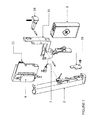
- FIG. 10 is an isometric exploded view of the components in the cartridge.
- the cartridge includes a body 20 made of a clear plastic material that is compatible with nicotine storage (such as HDPE—high density polyethylene; PETG—polyethylene terephthalate; or COC—cyclic olefin copolymers) with two apertures in its top face; the e-liquid inlet aperture 21 to the left side of the body is used when filling the cartridge on an automated or semi-automated filling line: 10 mL of e-liquid is passed into the cartridge through a filling head and then inert argon gas purges all oxygen from inside the cartridge to prevent oxidation of the nicotine.
- a bung 22 or other form of seal, then seals or closes off that aperture 21 .
- a rubber septum 24 sits in aperture 23 and is sealed in place with ring 25 and seals aperture 23 , which is the e-liquid outlet aperture.
- the septum 24 is a PTFE (polytetrafluoroethylene)/silicone/PTFE disc.
- the cartridge includes two apertures, (a) an outlet aperture 23 being sealed by a septum 24 designed to be penetrated or punctured by a needle or stem in the case that withdraws e-liquid from the cartridge and (b) an inlet aperture 21 being used to fill the cartridge on a filing line and then being covered with a bung or plug 22 .
- Aperture 21 enables fast and efficient filling on an automated filling line, reliable sealing of the cartridge to minimize contamination risk and also easy integration of the cartridge with the case, all at very low cost.
- An adhesive, tamper evident strip 26 is then applied over the top of the bung 22 and the septum 24 and ring 25 .
- the body includes a standard scavenger tube 27 fixed to the outlet 23 that leads to the rubber septum 24 , so that the last droplets of e-liquid in the cartridge can be extracted.
- An air pressure valve is included in the cartridge. If no air pressure valve is provided, then, as the cartridge empties, a partial vacuum forms, retarding fluid transfer out of the cartridge. The valve also prevents contaminants from entering the cartridge/reservoir, which hence preserves the condition and stability of the e-liquid. It also permits only limited quantities of air to enter the cartridge (e-liquid can deteriorate when exposed to free flowing air for long periods).
- the valve has the following structure.
- a lid 28 is positioned against one face of the cartridge body.
- the lid 28 includes a small air hole 29 to allow air to enter and leave a plenum 30 formed by the lid 28 as one face, and ridges in the lid 28 as the sides and a PorexTM PTFE sheet 31 facing the lid as the opposite face.
- the sheet can be any material that is impermeable to e-liquid but bi-directionally permeable to air, hence enabling air pressure equalization within the cartridge; PTFE is especially suitable because it is very stable in the presence of e-liquid, and so introduces no contaminants.
- the plenum 30 provides for a large surface area for the air/PTFE interface. Other materials apart from PTFE are possible; for example, paper coated with PTFE may be suitable.
- the air-side of the PTFE sheet 31 may include fine strands of polypropylene to increase the surface area and to facilitate welding to the clear plastic body 20 .
- each cartridge has its own unique serial number written in a One-Wire flash memory chip or authenticator 32 , such as the Maxim DS28E15 security chip.
- a microcontroller (MCU) in the case reads its serial number and verifies that its hash-function is valid. If the verification is good, the cartridge will be used to refill the PV. If not, the MCU in the case will block any liquid usage from such cartridge.
- MCU microcontroller
- microcontroller used in this specification includes other forms of processors, microprocessors, ASICs etc.
- the MCU can also write-data into the chip 32 —for example the estimated or measured amount of e-liquid left in the cartridge; this enables cartridges that have been unlawfully re-filled to be spotted by the MCU (since they can be tracked to have expelled significantly more than the known capacity of the cartridge—e.g. 10 mL) and can then be prevented from being used.
- the known capacity of the cartridge e.g. 10 mL
- FIG. 11 are side, top and front views of the cartridge.
- the total fluid capacity is 11.6 cc.
- the cartridge could include a bag-in-bottle or BiB system—e.g. this would allow the contents of the cartridge to be almost completely emptied, avoiding wastage, yet also protecting the contents of the cartridge from oxidation and contaminants.
- a material like DuPont Surlyn can be used for the inner bag.
- Section D describes these features in more detail.
- Section B3 Overview of the PV's Atomising Coil
- FIG. 12 is an isometric exploded view of the components in one type of wick and heating coil assembly.
- the wick 35 can take several different forms, such as a ceramic cell like the cCell from Shenzen Smoore Technology Limited, or a more conventional cotton wicking coil arrangement.
- FIG. 12 shows the latter; it shows a ‘z’ shaped piece of compressed cotton 35 or a porous ceramic with a body arranged longitudinally along the long axis of the PV electronic vaporiser in a vapourising chamber to interrupt the air flow path through that chamber.
- One end of the wick 35 includes an end section, angled at right angles with respect to the body, and protruding into an e-liquid reservoir; the other end of the wick includes an end section, also angled at right angles with respect to the body, and protruding into that e-liquid reservoir.
- a NiChrome wire heating element 36 is wound around the wick body 35 ; other materials for the heating element may also be used, such as titanium, tungsten and other materials; the key design criteria for material choice is to minimize the risk of any harmful products entering the user's lungs, particularly as the heating element starts to degrade.
- Coil assembly 37 is mounted inside tube 38 , closed off at one end by body 39 and at the other end by end cap 40 , which seals against ‘0’ ring 41 .
- Tube 38 forms the inner wall of the e-liquid reservoir; this small reservoir, capacity approximately 0.2 mL, surrounds tube 38 .
- the cotton wick 35 protrudes through a gap in the side of tube 38 into this reservoir, drawing e-liquid in from the reservoir.
- FIG. 12 design is especially easy to mass-assemble since it requires very few steps to complete. Also, because the heating element and wick runs longitudinally through the vapourising chamber, and there is no straight through path for air through the vapourising chamber, but instead the incoming air has to flow around and over the heating element and wick, the design provides a good quality vaping experience.
- FIG. 13 is a cross section through the fully assembled wick and coil assembly. It shows the e-liquid stainless steel feed pipe 42 (which is connected to the piezo micro-pump during filling and filled with e-liquid from the cartridge) that feeds the concentric reservoir, indicated generally at 44 , that surrounds tube 38 . E-liquid is pumped into the reservoir 44 and then drawn by the wick into the coil assembly. Air passes from inlet 45 and then has to divert up and around the coil and assembly 37 ; the chamber 43 is the atomizing chamber where heated micro-droplets of e-liquid are carried by the air passing over the coil out through aperture 46 . But requiring the airflow to divert up and around the coil assembly, vortices are formed which are more efficient at drawing out the micro-droplets of e-liquid.
- the fully assembled wick and coil assembly 50 is inserted into a coil holder 52 which serves as a mouthpiece; the coil holder 52 can then be press-fitted onto the main tube 51 of the PV that includes the battery, electronics and e-liquid filling aperture (which is at the end of the PV furthest from the mouthpiece).
- the combined mouthpiece/coil holder 52 can be readily removed from the tube and replaced with a new or different combined mouthpiece/coil holder; hence, as soon as there is any sign of degradation of the wick or coil, or perhaps the user simply wishes to try a different wick/coil design (since it may deliver different vaping characteristics), then the user can simply pull the old coil holder 52 off and insert a new one.
- the PV includes a front section 52 containing a wick and heating assembly but no e-liquid cartridge; the front section is removable to enable a replacement front section to be used, for example once the original wick or heating element starts to degrade. The rest of the PV can be re-used with a fresh front section 52 .
- the case has a micro-pump (e.g. piezoelectric or peristaltic or any other effective, reliable, accurate and low-cost form of pump), it can be used in reverse to fully drain the PV of e-liquid so that if the coil holder is replaced then there will be very little e-liquid to drip out.
- Activation of the reverse pumping can be through a control on the case, or via an app on a connected smartphone: for example, with the PV stored in the case, then the user opens up the associated app on his smartphone; one option is ‘drain PV if replacing coil holder’; when that is activated, then the app sends a control signal to the electronics module in the case, which in turn causes the micro-pump to operate to drain the PV fully.
- a ‘cleaning’ routine with unflavoured e-liquid is hence supported.
- the PV includes an air pressure valve or device so that excess air can escape from the e-liquid ‘child’ reservoir in the PV. Air needs to escape from the child reservoir in the PV when that reservoir is being filled up with e-liquid, and air needs to enter into the child reservoir as e-liquid is consumed in normal use, since otherwise a partial vacuum would be created, which would tend to prevent or retard e-liquid in the child reservoir wicking/entering the atomising coil unit.
- the PV air pressure relief system, used with the cotton-type wick of FIGS. 11-13 is shown in FIGS. 15-19 .
- FIG. 15 is an exploded view of the PV tip assembly.
- the coil wick assembly 50 shown in FIGS. 12, 13 and 14 , is inserted into a cast aluminium alloy LM25 tip casting 52 ; tip casting for the mouthpiece 52 is then inserted into the body 53 .
- Tip casting mouthpiece 52 includes the air pressure relief system; this includes a rounded rectangle shaped membrane 90 on one side of the mouthpiece 52 , secured by slug 91 .
- On the opposing face of the casting 52 is a second, circular PTFE membrane 92 , secured in place by slug 93 .
- a PTFE membrane instead of a PTFE membrane, other materials are possible; these materials must be porous to air, but impermeable to e-liquid.
- Sintered metal is one alternative material; a porous ceramic could also be used.
- FIG. 16 shows the FIG. 15 construction but from a different viewpoint.
- FIG. 17 is a cross-section view through this construction. There is an interference fit between each slug 91 , 93 and the body 53 ; this creates a compressive force on each PTFE membrane 90 , 92 , which each sit on bead 95 .
- FIG. 18 is a longitudinal cross-section through the X-X marked in FIG. 17 .
- the e-liquid feed pipe 42 that feeds the reservoir 44 .
- Air is displaced up past each PTFE membrane 90 , 92 and passes along an air vent channel 96 , 97 , formed in the top of tip casting 52 .
- FIG. 19A shows the fluid path 98 and the air path 99 (note that air can flow both in and out of the PV through this air path; if the air pressure inside the PV drops (for example, it is in an airplane flying at high altitude), then air needs to pass into the reservoir 44 to prevent e-liquid leaking out from the PV.
- FIG. 19B shows a perspective view of the air vent channel 96 formed in the top of tip casting 52 , with the arrows indicating the air escape path 99 .
- FIG. 19C shows a perspective view of the tip casting 52 with the slug removed.
- the cylindrical wall of the ceramic cell itself serves as the air-pressure valve because the wall is itself bi-directionally air-permeable.
- air can pass through the wall and into the atomizing chamber which vents to the outside.
- air pressure increases, then air can pass into the internal reservoirs in the PV via the ceramic walls—in both cases, this ensures that air pressure equalization is achieved, and without the need for an additional air pressure relief system as shown in FIGS. 15-19 .
- a ceramic cell however presents leakage challenges when being filled under pressure, as happens with the design we are describing.
- We solve this problem with a pair of silicone washers, end-caps or ‘0’ rings on either end of the cylindrical ceramic cell. This is shown in FIGS. 20-25 .
- the ceramic cell such as the T28 cCell from Shenzen Smoore, is a short cylinder 84 of ceramic material enclosing a helical heating wire 88 would along the inner bore of the cylinder.
- the heating wires are connected to a power bush 87 .
- E-liquid is drawn through the porous ceramic walls of the cylinder 84 , where it contacts the heated wires 88 and creates an atomized mist of e-liquid vapour in the atomizing chamber 43 , from where it is drawn out by a user's inhalation.
- a ceramic cell is typically wrapped in cotton and then placed within a metal tube; e-liquid wets the cotton, forming an e-liquid reservoir around the ceramic coil, and is then wicked through the ceramic walls. Where the user manually drips e-liquid into this sort of atomizing unit, then it performs well. However, where the e-liquid reservoir around the ceramic coil is pumped under pressure, as it will be with the piezo-pump based system we have been describing, then a cotton wrap will leak and will also lead to very uneven wetting of the ceramic coil. We solve these problems by providing silicone end-caps 85 and 86 around the ceramic coil 84 .
- the section of the ceramic coil 84 that is not covered by the silicone end-caps 85 and 86 is approximately 2 mm wide, but that is sufficient to receive e-liquid and distribute it evenly through the ceramic walls 84 .
- a cotton strip may also be wrapped around this exposed section of the coil to reduce ingress of e-liquid.
- FIG. 23 shows a cross-sectional view of the components in the removable and user-replaceable mouthpiece 52 , including the ceramic cell 84 .
- the ceramic cell 84 with silicone end-caps 85 , 86 is placed within metal tube 38 .
- Metal tube 38 includes an opposing pair of circular e-liquid inlet apertures (approx. 2 mm in diameter) that line up over the section of the ceramic coil 84 that is not covered by the silicone end-caps 85 , 86 .
- Metal tube 38 is placed within tip tube 51 ; the annular region forms an e-liquid reservoir 44 around the metal tube 38 ; an e-liquid feed tube supplies e-liquid into this reservoir 44 .
- a front seal 47 and back seal 49 seal off each end of the reservoir.
- a silicone rubber stopper 48 closes off one-end of the tube 38 , and includes a central aperture 46 through which e-liquid vapour, created in the atomizing chamber 43 , can pass.
- a front tip 89 defines the front face of the mouthpiece
- silicone end caps make the coil more robust and impact resistant because they form protective silicone barriers. Because silicone is a good thermal insulator, it prevents the tip from getting too hot and burning a user's lips; it also improves the thermal effectiveness of the heating element. Instead of silicone, another suitable material, such as rubber or a soft plastic, or another type of elastomer, could be used. Material requirements are that it can (i) form an effective seal around the ceramic unit; (ii) withstand high temperatures; (iii) will not introduce any toxic compounds into the e-liquid and (iv) is easy to mold around the ceramic unit and (v) is thermally insulating.
- FIG. 24 is an enlarged view cross-sectional view of the ceramic coil 84 , silicone end-caps 85 , 86 and silicone rubber stopper 48 (but facing in the opposite direction compared with FIG. 23 ).
- FIG. 25 is an exploded view of all the mouthpiece components shown in cross-section in FIG. 23 .
- FIG. 26 shows the entire electronic vaporiser PV, with the mouthpiece or coil holder 52 at one end (and which includes the components shown in FIG. 25 ); the main body tube 53 , and at the far right hand end the e-liquid filling end, including a check valve assembly 54 .
- FIG. 27 is an exploded view of the main body. It includes an external tube 53 , and a chassis 55 which holds the main components, including a battery 56 and a fluid tube 42 that passes e-liquid from the e-liquid filling end (not shown) up through the main body and into the reservoir surrounding the wick and coil assembly (not shown).
- a small electronics PCB 58 which includes a small processor or MCU and digital I/O; power and data I/O is via two metal rings sitting round the outside of the tube, as will be described later.
- PCB 58 can also be placed running above the battery, close to one of the main faces of the external tube 53 .
- the PCB 58 includes an IMU (inertial measurement unit) to detect when it is being lifted up and out of the case to control and/or track certain behaviours.
- the IMU is connected to a microcontroller (MCU) in the PV.
- MCU microcontroller
- the PV can also sense when a user is touching it—e.g. with a capacitive sensor. This provides a control signal to the MCU in the PV and hence enables movement associated with the user holding the PV to be distinguished from other movement of the PV.
- An airflow sensor 59 is used to detect airflow and to activate the heating element.
- PCB also includes a temperature sensor.
- the airflow sensor 59 can also be used to operate as a spirometer—for example, measuring air flow and/or peak flow when the user is both sucking and blowing into the PV, and without activating the vaping function. This could be very useful for smokers with compromised lung functioning who wish to have a simple way of tracking the improvement in lung function that is very likely associated with giving up smoking; this can be an added motivation to continue with a smoking cessation programme based on using this device.
- the spirometer data captured by the airflow sensor can be sent to the user's app and displayed on the smartphone running the app and also shared with a physician.
- the MCU in the PV can measure or estimate coil resistance; if the coil resistance is higher than some limit we can say that the coil needs to be replaced. Likewise, if the resistance starts to fluctuate, then that is also an indication that the coil needs replacing.
- the MCU in the PV directly measures current and voltage delivered to the coil; it calculates coil resistance from this data.
- each specific type of coil e.g. design, materials, type of heating coil etc.
- has a unique resistance profile which can be seen when a small current is passed through the coil (this is done momentarily before the full current for heating purposes is applied).
- This resistance profile is detected by the microcontroller, which in turn compares it to stored profiles to find the best match; the microcontroller then uses knowledge of the likely type of coil being used to ensure that it is used optimally—for example, different coil types could have different optimal operating temperatures and maximum safe temperatures.
- the optimal temperature is approximately 130° C.
- the MCU is able to determine the coil temperature through empirical mapping of the detected resistance against previously calculated or directly measured temperatures; accuracy is approximately ⁇ 10° C. or better.
- accuracy is approximately ⁇ 10° C. or better.
- We set the maximum coil temperature at 150° C. since temperatures higher than 160° C. could be associated with the release of undesirable contaminants.
- Different optimal and maximum temperatures will be a function of the specific coil material and coil assembly design (e.g. a ceramic coil can operate at higher temperatures), and the e-liquid being used. Since the specific type of e-liquid (including flavours, water content, PV/VG mix etc.) being used by the device is known from data in the cartridge, this data is used by the MCU to set the optimal and maximum temperatures.
- the PV also includes an integral temperature sensor measuring ambient temperature and feeding that data to the MCU; if the air is at ⁇ 5° C., then the PV will deliver significantly more power to the coil than if the air temperature is +30° C., in order to achieve optimal 130° C. operating temperature.
- pre-heat can start rapidly and at high power to ensure that the coil is at the optimal temperature when the first inhalation is taken.
- the MCU in the PV also monitors each inhalation to measure e-liquid consumption and heating coil degradation.
- a power wire 60 is shown, together with rear electrically insulating spacer 61 , power plate 62 connected to the power wire 60 , and front electrically insulating spacer 63 .
- Power plate 62 provides power from battery 56 to the heating coil assembly.
- FIG. 28 shows an exploded view of the e-liquid filling end, which is the check valve assembly 54 in FIG. 26 .
- check valve body 70 On check valve body 70 are mounted (moving from right to left in the Figure) a power ring 71 , an insulating ring 72 , a second power ring 73 , a further insulating ring 74 and a third power ring 75 .
- Electrical contact pins 76 , 77 and 78 pass through the rings. Both power and data is sent via these power rings.
- the e-liquid filling or stop valve Inside the check valve body 70 is the e-liquid filling or stop valve. It includes spring 80 mounted on spring guide 79 ; the spring 80 biases stainless steel 316L ball 81 , and ball 81 acts as the stop valve.
- the e-liquid filing mechanism in the PV is hence a simple aperture or nozzle sealed with spring biased stainless steel 316L ball.
- a short filing tube or stem or spigot 83 at the base of the hinged holder pushes the ball 81 off its seat 82 , exposing a fluid transfer path up from the filing tube, past the steel ball 81 and up through the PV to the ‘child’ reservoir around the wick and coil assembly.
- the piezo pump can be activated manually by a user touching a button or other hard or soft switch on the case; alternatively, the case can be set up to automatically always fill the PV up whenever the PV is returned to the case and the case shut.
- filing automatically ends when the electronics in the case determines that the PV has sufficient e-liquid; for example, the electronics can monitor the power, current or voltage used by the micro-pump; this will start to rise as the PV reaches full capacity; the micro-pump can then be automatically switched off (or even momentarily switched into reverse to withdraw a small amount of e-liquid from the PV so there is no possibility of overfilling the PV).
- a stop valve is included at the base of the spigot 83 .
- This is a simple ball valve that is biased closed but is pushed open when the PV is fully inserted into the case to enable e-liquid to flow past it. Once the PV is removed, the ball valve returns to its closed position, preventing any liquid from spilling from the filing tube or spigot 83 . This is shown in FIG. 9B .
- a small, spring loaded, damped plug sits around the short filing tube or stem or spigot and causes the PV to be gently raised up when the hinged holder is opened; the PV rises about 5 mm to enable easy extraction from the case, mimicking the ritual of being offered a cigarette from a pack.
- FIGS. 31 and 32A and 32B are various cross-sectional views through the PV that uses a cotton wick.
- the PV (whether using a cotton wick or a ceramic cell) is the approximate same size as an ordinary cigarette, approximately 10 cm in length and 1 cm in width.
- the cross-section is square, with rounded corners (a ‘squircle’): this shape enables a long, rectangular circuit board to be included in the PV and gives more design freedom for the placement of that PCB: if the PV casing, was circular, then the PCB would likely have to be mounted exactly across a diameter, and that would leave little room for a battery.
- the square cross-section is a much better shape if a long PCB and battery is to be included inside the casing since it allows the PCB to be placed very close to one of the long faces of the PV, hence liberating volume for the battery.
- the PV includes a narrow pipe to transport e-liquid from the filling end to the reservoir around the heating element; this pipe can be accommodated in the corner of the PV casing just above the PCB.
- the square-profiled tube with rounded corners is hence an effective shape for including these elements.
- the steel ball valve 81 is shown off its seat 82 although in normal vaping it will be biased against and sealing against its seat.
- e-liquid passes up past ball valve 81 , along fluid tube 57 and into reservoir 44 .
- E-liquid passes from reservoir 44 along wick 35 into the atomizing chamber.
- the MCU on board 58 then sends power from the battery 56 to the heating coil 36 , which rises to 130° C. and rapidly heats the e-liquid in the wick 35 , causing it to vapourise; the vapour is carried out from outlet 46 into the user's mouth.
- FIGS. 33A to 33C are cross-sectional views of the PV that uses a ceramic cell 84 .
- e-liquid is filled into the PV, moving past stainless steel ball valve 81 , passing along feed tube 42 into e-liquid child reservoir 43 that surrounds the ceramic cell 84 .
- E-liquid wicks into the ceramic cell 84 through apertures 57 .
- Vapour is inhaled from outlet aperture 46 .
- the entire mouthpiece unit 52 can be clipped off and on the body 53 if desired, enabling mouthpiece to be replaced if needed.
- the main PCB 58 sits over the battery 56 .
- FIGS. 34A and 34B are external views of the ceramic cell-based PV.
- PV Feature 1 PV includes an air pressure valve
- PV Feature 2 PV includes a mechanical valve that is pushed up from its seat when filling takes place
- PV Feature 3 PV or case has an IMU
- the PV includes a touch sensor
- PV Feature 5 ‘z’ wick heating coil
- PV Feature 6 PV with replaceable wick and coil
- PV Feature 7 Pulsed power to the coil
- PV Feature 8 Detecting coil degradation
- PV Feature 9 Estimating coil temperature
- PV Feature 10 Monitoring each inhalation to measure e-liquid consumption and heating coil degradation
- PV Feature 11 Monitoring the coil characteristics to identity the type of coil installed.
- PV Feature 12 Monitoring external or ambient temperature to ensure the coil is at optimal operating temperature
- PV Feature 13 Monitoring airflow to ensure the coil is at optimal operating temperature
- PV Feature 14 Using data from cartridge defining the e-liquid to control the heating of the coil
- PV Feature 15 The PV has a squircle cross-section
- PV Feature 16 Silicone caps to the ceramic cell
- Section D describes these features in more detail.
- FIGS. 35 and 36 are flow charts explaining the operation of the electronic vaporiser.
- the innovative features can also be applied in an inhalation system providing substances other than nicotine—for example, medication, such as asthma medication or any other drug that can be effectively delivered into the lungs, and also vitamins, and recreational drugs such as marijuana (where their use is lawful).
- medication such as asthma medication or any other drug that can be effectively delivered into the lungs
- vitamins, and recreational drugs such as marijuana (where their use is lawful).
- e-liquid can hence be generalized to any substance, including any medication, or legally permissible recreational drug.
- Case Feature 1 The case includes a piezo-electric pump
- Case Feature 2 The case or PV has a ‘discrete’ mode
- Case Feature 3 The case or PV includes a ‘power mode’ with coil temperature monitoring
- Case Feature 4 The case has a PV ejection mechanism
- Case Feature 5 A non-contact sensor in the case detects PV release from the case
- Cartridge Feature 1 The cartridge or other form of parent reservoir includes an air pressure valve
- Cartridge Feature 2 The cartridge includes a memory chip
- Cartridge Feature 3 The cartridge includes two e-liquid apertures
- Cartridge Feature 4 The cartridge stores the batch number of the e-liquid it is filled with and can be remotely disabled from using specific batch numbers
- PV Feature 1 PV includes an air pressure valve
- PV Feature 2 PV includes a mechanical valve that is pushed up from its seat when filling takes place
- PV Feature 3 PV or case has an IMU
- the PV includes a touch sensor
- PV Feature 5 ‘z’ wick heating coil
- PV Feature 6 PV with replaceable wick and coil
- PV Feature 7 Pulsed power to the coil
- PV Feature 8 Detecting coil degradation
- PV Feature 9 Estimating coil temperature
- PV Feature 10 Monitoring each inhalation to measure e-liquid consumption and heating coil degradation
- PV Feature 11 Monitoring the coil characteristics to identity the type of coil installed.
- PV Feature 12 Monitoring external or ambient temperature to ensure the coil is at optimal operating temperature
- PV Feature 13 Monitoring airflow to ensure the coil is at optimal operating temperature
- PV Feature 14 Using data from the cartridge defining the e-liquid to control the heating of the coil
- PV Feature 15 The PV has a squircle cross-section
- PV Feature 16 Silicone caps to the ceramic cell
- the case includes a piezo-electric pump: the case (or the PV or the cartridge) includes a piezo-electric pump to transfer small but accurate quantities of e-liquid in from the cartridge or parent reservoir to a child reservoir in the PV. This enables mixing from multiple cartridges too.
- the piezo-electric pump can be used as the fluid transfer mechanism to transfer e-liquid from the cartridge or parent reservoir into the child reservoir in the PV. It can also be used in reverse to suck back out any residual e-liquid in the PV.
- the PV (or case or cartridge or an associated application running on a smartphone) can accurately determine the total consumption of e-liquid and/or the amount of e-liquid remaining in a cartridge and also in the PV itself.
- This in turn can be used in the automatic re-ordering function—for example, when the system knows that the cartridge is down to its last 20% by volume of e-liquid, then the app running on the user's smartphone can prompt the user with a message asking if the user would like to order a replacement cartridge or cartridges.
- Low-cost piezo-electric pumps used ordinarily for delivering ink in an inkjet printer may be used, as well as more costly pumps, such as those made for pumping blood plasma. Note that the piezo-electric pump is quite a high cost item and so suitable for premium category electronic vaporiser devices. Where minimizing costs is critical, then a mechanical pumping arrangement, as for example described in WO 2015/128665, can be used instead.
- the pump operates at low pressure, under 1 psi (higher pressures are possible) and has a flow rate of 0.4-0.6 mL per minute, and hence will fill a completely empty PV in 60-90 seconds (or half that if the PV has been used to vape a single session after its last complete filling since it is already half-filled).
- the pump can be activated manually by a user touching a button or other hard or soft switch on the case; alternatively, the case can be set up to automatically always fill the PV up whenever the PV is returned to the case and the case shut.
- filing automatically ends when the electronics in the case determines that the PV has sufficient e-liquid; for example, the electronics can monitor the power, current or voltage used by the micro-pump; this will start to rise as the PV reaches full capacity; the micro-pump can then be automatically switched off (or even momentarily switched into reverse to withdraw a small amount of e-liquid from the PV so there is no possibility of overfilling the PV).
- the micro-pump can also be operated in reverse, or with rapid forward and reverse pumping, to clear a blockage or clean the system.
- a sensor can be placed in the inlet tube feeding the piezo-pump to determine if air or e-liquid is about to enter the piezo-pump: the pumping frequency for e-liquid has to be significantly lower for efficient pumping of e-liquid; or other parameters can also be altered to ensure pumping effectiveness. Also, the viscosity of the e-liquid affects the piezo-pump and as the viscosity increases, the pumping frequency should be lowered. The viscosity could be directly measured using an appropriate sensor (e.g. a MEMS sensor) or could be inferred from the ambient temperature and/or the temperature of the e-liquid (viscosity is temperature dependent).
- an appropriate sensor e.g. a MEMS sensor
- An electronic cigarette vaporiser system including a single piezo-electric pump that both withdraws liquid from a cartridge or chamber and also pumps controlled amounts of e-liquid for atomizing in the vaporizer.
- Optional features include one or more of the following:
- An e-cig system including a piezo-electric micropump operating to extract e-liquid from a user-removable cartridge.
- An e-cig system including a piezo-electric micropump operating to transfer e-liquid into a reservoir in a PV.
- An e-cig system including a peristaltic micropump operating to extract e-liquid from a user-removable cartridge.
- An e-cig system including a peristaltic micropump operating to transfer e-liquid into a reservoir in a PV.
- an electronic vaporiser system including a single piezo-electric pump to withdraw e-liquid from an e-liquid cartridge or chamber and a further piezo-electric pump to pump controlled amounts of e-liquid into another reservoir in the electronic vaporiser.
- a storage case for an electronic cigarette vaporiser in which the case includes:
- a user-replaceable, closed e-liquid cartridge that slots into or otherwise attaches to the case, the cartridge including a septum that seals an aperture in the body of the cartridge;
- a piezo-pump connected to the needle or stem to withdraw e-liquid from the cartridge and to pump it to the vaporiser when the vaporiser is positioned in the storage case and the user either activates a control switch (e.g. on the case, and/or on an app) or (ii) e-liquid filling is started automatically.
- a control switch e.g. on the case, and/or on an app
- a case for storing, re-filling with e-liquid and re-charging an electronic cigarette vaporiser in which the case includes a piezo-electric pump to transfer quantities of e-liquid to a child reservoir in the personal vaporiser.
- a piezo-electric pump adapted to be operable to withdraw e-liquid from an e-liquid cartridge or reservoir and to pump controlled amounts of e-liquid into a reservoir or chamber in an electronic cigarette vaporiser.
- the adaptation can be the specific choice of materials used in the piezo-pump, in order for there to be nicotine compatibility, such as the use of polyimide materials.
- Case Feature 2 Case or PV has a ‘discrete’ mode: PV includes a ‘discrete mode’—e.g. to reduce the amount of vapour produced, the user can activate a button or sensor on the PV (or case, or connected app) and that alters the operation of the operation of the atomising device in such a way as to decrease the vapour produced—for example, it could reduce the power used, or increase the VG proportion compared to PG, if that is possible—e.g. the case or PV can mix differing proportions of PG and VG, or alter the frequency or other operational parameters (e.g. duty cycle) of a piezo-electric, thermal bubble jet or ultrasonic atomiser.
- a ‘discrete mode’ e.g. to reduce the amount of vapour produced, the user can activate a button or sensor on the PV (or case, or connected app) and that alters the operation of the operation of the atomising device in such a way as to decrease the vapour produced—for example, it could reduce the power used, or
- the density or thickness of the vapour produced by the PV can be significantly reduced; this is particularly useful indoors, when the user might wish to vape very discretely.
- the strength of the ‘hit’ can also be decreased too, because the amount of nicotine inhaled will be reduced; this can be useful where the user wishes to reduce their nicotine consumption.
- An electronic cigarette vaporiser system operable in a ‘discrete’ mode to reduce the amount of vapour produced by a vaporiser that forms part of the system, compared to a normal mode.
- Optional features include one or more of the following:
- Case or PV includes a ‘power mode’—e.g. to increase the amount of vapour produced, the user can activate a button or sensor on the case or PV, or connected app and that alters the operation of the operation of the atomising device in such a way as to increase the vapour produced—for example, it may increase the power used, or increase the frequency or duty cycle of a piezo-electric, thermal bubble jet or ultrasonic atomizer, but whilst monitoring the coil temperature to ensure that excessively high temperatures, associated with undesirable compounds in the vapour, are not reached.
- a ‘power mode’ e.g. to increase the amount of vapour produced
- the user can activate a button or sensor on the case or PV, or connected app and that alters the operation of the operation of the atomising device in such a way as to increase the vapour produced—for example, it may increase the power used, or increase the frequency or duty cycle of a piezo-electric, thermal bubble jet or ultrasonic atomizer, but whilst monitoring the coil temperature to ensure that excessive
- the system may increase the PG proportion compared to VG, if that is possible—e.g. the case or PV can mix differing proportions of PG and VG, Consequently, the density or thickness of the vapour produced by the PV can be significantly increased; the strength of the ‘hit’ can also be increased too, because the amount of nicotine inhaled will be greater.
- An electronic cigarette vaporiser system operable in a ‘power’ mode to increase the amount of vapour produced by a vaporiser that forms part of the system, whilst monitoring the temperature of a heating element in the vaporiser to ensure that excessively high temperatures, associated with undesirable compounds in the vapour produced by the heating element, are not reached.
- Optional features include one or more of the following:
- Case Feature 4 Case has a PV ejection mechanism:
- the case includes an automatic lifting mechanism (e.g. magnetic or spring-based) that, when the case is opened, gently lifts the PV up a few mm from the case to enable a user to easily grasp it and may also prevent it from falling out if tipped upside down.
- a mechanical lifting system could be a simple pivoting lever that contacts a part of the PV (e.g. its front face); a damped spring is placed under tension if the PV is inserted fully into the case; when the PV is released from the case (e.g. by pushing a release button), then the lever cause the PV to gently rise up by about, for example, 12 mm.
- a magnetic lifting mechanism could involve a permanent magnet at one part of the PV and an adjacent electro-magnet placed in the case and powered by the main battery in the case; slowly energising the electro-magnet when the PV needs to be released causes the PV to gracefully rise up out of the case.
- a case for an electronic cigarette vaporiser including an automatic lifting mechanism (e.g. magnetic or spring-based) that gently lifts the vaporiser up a few mm from the case to enable a user to easily grasp the vaporiser and withdraw it from the case.
- an automatic lifting mechanism e.g. magnetic or spring-based
- Optional features include one or more of the following:
- a non-contact sensor detects PV release from the case:
- a non-contact sensor e.g. a magnetic sensor, such as a reed switch, Hall effect sensor etc.
- a non-contact switch like a magnetic sensor has the advantage of being robust and reliable and does not affect the smooth, tactile quality of inserting and withdrawing the PV from the case, unlike physical (e.g. electrical) contacts.
- a light sensor could be used; for example, a light sensor in the PV could detect when light was incident on the PV, inferring that the PV is now in an open case or no longer in the case at all; alternatively, the case could include a small light sensor facing a LED light source in the case; withdrawal of the PV triggers the light sensor since light from the LED is now incident on the sensor.
- a light sensor in the PV could detect when light was incident on the PV, inferring that the PV is now in an open case or no longer in the case at all; alternatively, the case could include a small light sensor facing a LED light source in the case; withdrawal of the PV triggers the light sensor since light from the LED is now incident on the sensor.
- Many variants of sensor are possible. When withdrawal of the PV is detected by the PV, it can automatically start heating the atomising coil so that the PV is at its optimal operational temperature when the user takes his first vape.
- An electronic cigarette vaporiser system that includes a case and a vaporiser that is stored in the case, and the system includes a non-contact sensor that detects release or withdrawal of the vaporiser from the case.
- the e-liquid feed or inlet tube includes a sensor that can detect whether the feed into the piezo micro-pump is liquid or air; this is very useful to know because the piezo-pump operates in different modes depending on the viscosity of the material being pumped. So being able to automatically alter the cycle time or frequency of the piezo-pump, based on an automatic assessment of the substance being pumped, is very useful.
- An electronic cigarette vaporiser system including a piezo-electric pump that pumps e-liquid into an electronic vaporizer, in which a sensor detects whether air or e-liquid is present in the liquid feed line into the piezo-electric pump and adjusts an operating parameter of the pump accordingly.
- each actuator over time, starts to operate slightly differently.
- Proper operation of the pump requires both actuators to operate identically, delivering exactly the same quantity of liquid for each pumping stroke. Pumping performance can drop significantly over time because of this mis-match in operation and output.
- a microcontroller can independently adjust the phase or timing or power of each voltage pulse that triggers a piezo-actuator until both actuators are operating together in the most optimal manner.
- An electronic cigarette vaporiser system including a piezo-electric pump with multiple piezo-actuators, in which a microcontroller independently adjusts the phase or timing or power of each voltage pulse that triggers a piezo-actuator.
- Another aspect is a piezo-electric pump with multiple piezo-actuators, in which a microcontroller independently adjusts the phase or timing or power of each voltage pulse that triggers a piezo-actuator in the piezo-pump.
- a microcontroller continuously or regularly monitors the efficiency or performance of the entire pump and adjusts the phase, timing, or power delivered to each piezo-actuator relationship until or so that the optimum pumping performance is achieved.
- Cartridge Feature 1 The cartridge or other form or parent reservoir includes an air pressure valve. As the fluid level inside the cartridge/reservoir falls (e.g. because fluid is being transferred into the child reservoir in the PV), atmospheric pressure forces open the air pressure valve to allow air to flow in and ensure equalisation of the air pressure. Air pressure equalisation or normalisation is also important whenever the ambient air pressure alters (e.g. when in an aircraft) or the temperature changes, causing the e-liquid in the cartridge to expand or contract, since it prevents the e-fluid leakage that might otherwise occur. If no air pressure valve is provided, then, as the cartridge empties, a partial vacuum forms, retarding fluid transfer out of the cartridge.
- the valve also prevents contaminants from entering the cartridge/reservoir, which hence preserves the condition and stability of the e-liquid.
- the cartridge is non-refillable, tamper evident and with an airtight seal to preserve e-liquid stability during transit and storage.
- the cartridge lid includes a small air hole to allow air to enter and leave a plenum chamber formed by the lid as one face, and ridges in the lid as the sides and a PTFE sheet facing the lid as the opposite face.
- the PTFE sheet is impermeable to e-liquid but permeable to air, hence enabling the air pressure equalization within the cartridge.
- the plenum provides for a large surface area for the air/PTFE interface.
- the PTFE membrane is typically constructed from PTFE Powder that is sintered and formed into a bulk microporous structure.
- the membrane is in the form of a rectangle approximately 50 mm ⁇ 10 mm, and 0.25 mm thick, giving a large surface area. This is ultrasonically fused with the lid moulding window aperture of a similar size.
- the cartridge material is HDPE, which can be effectively ultra-sonically welded to PTFE.
- Other materials than PTFE may be used if they have the right properties of being impermeable to e-liquid, but permeable to air; for example, PTFE coated paper may be suitable.
- a simple mechanical e.g. a duckbill valve, could be used instead.
- This cartridge may include each of the features defined above.
- Cartridge Feature 2 Cartridge with Chip
- each cartridge has its own unique serial number written in a One-Wire flash memory chip (we use the term ‘chip’ to refer to a solid state memory, microcontroller or microprocessor).
- the chip is a Maxim DS28E15 security chip or authenticator. After a cartridge is installed, the case reads the cartridge's serial number and verifies whether its hash-function is valid. If the verification is okay, the cartridge will be used to refill the e-cig. If not, the case will block any liquid usage from this cartridge.
- the memory chip is the same sort type of chip used on ink-jet cartridges and its operation is the same.
- the cartridge internal memory stores the liquid level too.
- the case measures or infers the quantity of e-liquid pumped from the cartridge and stores a record of the estimated e-liquid left in the cartridge (it assumes the cartridge started with 10 mL of e-liquid).
- the case writes this value into the cartridge. If the cartridge is removed but not entirely used it will keep its last liquid level in memory.
- the case also stores this liquid level. When the cartridge is installed back into the case, then the case will read and use this number. A cartridge can be transferred to a different case and that new case will read out the correct liquid level for that cartridge and write the new level after some use back into the cartridge.
- Reading and storing serial numbers also allows the case to gather usage statistics and send it over the Internet to the factory database (see above).
- Each cartridge has information about when and where it was produced, and any tax due and when it was paid. Using this information and current time and data from the user's smartphone we can detect if liquid in the cartridge is out-of-date or a counterfeit.
- An e-liquid cartridge designed to provide e-liquid for an electronic cigarette vaporiser system, the cartridge including a chip that stores and outputs a unique identity for the cartridge and/or data defining the e-liquid stored in the cartridge, and the cartridge being adapted to be inserted into or form an integral part of the electronic vaporiser system.
- An cartridge designed to provide liquid for an electronic vaporiser system including a chip that stores and outputs (i) a unique identity for the cartridge and (ii) data defining the liquid stored in the cartridge, and the cartridge being adapted to be inserted into or form an integral part of the electronic vaporiser system.
- Cartridge Feature 3 Cartridge with Two Apertures
- the first aperture being used to fill the cartridge on a filing line and then being covered with a bung or plug or other form of seal and the second aperture being sealed by a septum or other form of seal that is designed to be penetrated or punctured by a needle or stem that, in use, withdraws e-liquid from the cartridge.
- a cartridge designed to provide liquid for a vaporiser including:
- the first aperture being used to fill the cartridge on a filing line and then being covered with a bung or plug or other form of seal and the second aperture being sealed by a septum or other form of seal designed to be penetrated or punctured by a needle or stem that, in use, withdraws liquid from the cartridge.
- Cartridge Feature 4 The Cartridge Stores the Batch Number of the e-liquid it is Filled with and can be Remotely Disabled from Using Specific Batch Numbers
- a batch is identified as potentially harmful, then we can send a signal from a server that is received by the app running on a user's smartphone, which in turn is used to send a message to the case with the affected batch number or unique IDs.
- the case can then store that batch number and/or unique IDs and then compare the batch number or unique IDs of every cartridge inserted into the case with that stored number; where there is a match, then the case can disable or prevent use of that affected cartridge and also write warning data onto the chip of that cartridge to prevent any further use.
- a warning message can then be displayed on the case and the user's smartphone alerting them that a different cartridge should be used instead.
- the microcontroller in the case can check whether the date of manufacture is within required tolerance—for example 6 months if the shelf life is 6 months and prevent use if the cartridge is older than 6 months.
- An electronic cigarette vaporiser system including a cartridge designed to provide a liquid or other substance for the electronic vaporiser system, the cartridge including a chip that stores data related to the batch number of the substance stored in the cartridge, and the cartridge being adapted to be inserted into or form an integral part of the electronic vaporiser system.
- PV Feature 1 PV includes an air pressure valve: the PV includes an air pressure valve or device so that excess air can escape from an e-liquid ‘child’ reservoir in the PV.
- the ‘child’ reservoir is the reservoir in the PV that is directly filled by a ‘parent’ reservoir; the ‘parent’ reservoir can be an e-liquid cartridge that is removable from the PV or case.
- This child reservoir is designed to enable an atomizing coil unit to draw in controlled amounts of e-liquid for vaping; e-liquid in the secondary child reservoir is typically wicked into the atomising coil unit.
- the parent reservoir typically a user-removable and replaceable, sealed or closed e-liquid capsule or cartridge, perhaps of capacity 5 mL or 10 mL
- a fluid transfer mechanism operates to transfer e-liquid from the capsule or cartridge into the ‘child’ reservoir in the PV, typically 2 mL or less (it is 0.2 mL in the illustrated implementation).
- the heating coil unit is arranged to gradually wick or otherwise transfer some of the e-liquid up from the child reservoir in normal vaping operation.
- the valve will operate to ensure that the air pressure in the reservoir can rapidly and reliably equalise to ambient air pressure in the aircraft cabin, again preventing leakages of e-liquid from the PV.
- the PV includes a valve that, for example, equalises the air pressure in the PV to ambient air pressure, or alters it to bring it closer to ambient air pressure (‘normalising’) in order to prevent leakage when filling the PV with e-liquid and to ensure correct operation whilst the PV is consuming e-liquid.
- a valve that, for example, equalises the air pressure in the PV to ambient air pressure, or alters it to bring it closer to ambient air pressure (‘normalising’) in order to prevent leakage when filling the PV with e-liquid and to ensure correct operation whilst the PV is consuming e-liquid.
- the air-pressure valve or device could have no moving parts, but instead be a barrier made of an air-porous material, such as a sintered polymer or metal, coated with or otherwise including a barrier or layer of an air-porous substance that is not porous to e-liquid, such as an oleophobic material or a hydrophobic or super-hydrophobic material, for example, PTFE or a suitable porous ceramic.
- the air-pressure valve or device could be positioned to allow air to flow out from the ‘child’ reservoir. Equally, it will allow air to flow into the child reservoir as e-liquid is consumed and also as ambient pressure rises (e.g. as an aircraft descends from high altitude).
- suitable oleophobic materials are sintered phosphor bronze, sintered stainless steel and sintered PU plastic.
- the air valve is separate from the wick.
- a ceramic coil typically a hollow ceramic wicking cylinder with an embedded heating coil wound within the hollow core
- the ceramic material itself acts as the air valve since the ceramic itself is air-permeable.
- An electronic cigarette vaporiser that includes an air pressure valve or device to enable excess air to escape from an e-liquid reservoir in the vaporizer during pressurized filling of the vaporizer with e-liquid.
- PV Feature 2 PV includes a mechanical valve that is pushed up from its seat when filling takes place:
- the PV includes a mechanical valve that opens when the PV is being filled—for example, a nozzle or stem from the re-fill case or cartridge is inserted into an e-liquid filling aperture in the PV (or as the PV is inserted into the re-fill case or cartridge) for filling the PV with e-liquid.
- This causes the valve, situated just behind the e-filling aperture, to be pushed open or rise up from its seat, moving against the bias force of a small spring, so that e-liquid can freely flow through the nozzle or stem into a child reservoir in the PV.
- the valve When the nozzle or stem is withdrawn (e.g. the PV is withdrawn from the re-fill case or the filling cartridge or capsule withdrawn from its filling position in the PV where that capsule fits directly into the PV and there is no separate re-fill and re-charge case) then the valve automatically closes by resting back on its seat.
- the nozzle or stem e.g. the PV is withdrawn from the re-fill case or the filling cartridge or capsule withdrawn from its filling position in the PV where that capsule fits directly into the PV and there is no separate re-fill and re-charge case
- the child reservoir here includes a feed pipe that leads into a second child reservoir which surrounds the atomising unit and from which e-liquid is drawn (e.g. by a wick or other porous member) into the atomising chamber (e.g. a heating coil inside an air chamber).
- the valve sits back down under the biasing force of a small spring and the valve then re-seals against its seat, preventing leakage of any e-fluid out from the child reservoir in the PV. Ensuring that there is no leakage from the e-liquid filling process is especially important if the filling nozzle or aperture in the PV is at the same end as the inhalation nozzles, but this solution applies irrespective of where the filling nozzle or aperture is located.
- a electronic cigarette vaporiser that includes a mechanical valve that is (i) pushed up from its seat to enable automatic filling of the vaporiser with e-liquid from a fluid transfer mechanism and (ii) returns to seal against its seat at other times when the vaporiser is being vaped or inhaled from (e.g. when filling is complete).
- PV or case has an IMU:
- the PV includes an IMU (inertial measurement unit) to detect when it is being lifted up and out of the case so it can start heating (e.g. activate the atomising coil); it can also tell if it is left on a table and so can power down.
- Movement-related data can be stored and uploaded to a server (for example, sent over Bluetooth to the user's connected smartphone, which in turn sends it to the server). Movement data can be combined with data from the pressure activated sensor or switch that detects an inhalation. This data can be useful since it shows how the PV is being used, the duration of a vaping session etc. Fully instrumenting the vaporiser in this way, including tracking the time of day of all events, generates data that could be very powerful for scientists and regulators seeking to better understand how these products are being used, as well as to enable designers to improve the system.
- the case also senses its movements using an IMU or accelerometer; the case and the e-cig PV also have capacitive sensors to check if one or both of them are actually in the user's hand. This allows the case to safely update the PV firmware by detecting that it is not in the user's hand and laying still, therefore the PV is not going to be removed which may corrupt the firmware. This also allows the case to stop any refilling process if it is upside down.
- An electronic cigarette vaporiser that includes an IMU (inertial measurement unit).
- Another feature is an electronic vaporiser case that includes an IMU (inertial measurement unit) to detect when it is being handled.
- IMU intial measurement unit
- the PV includes a touch sensor: The PV and/or the case can sense when you are touching it—e.g. with a capacitive sensor. It can be programmed to detect specific touch inputs and control the PV accordingly. For example, the touch inputs are not merely to either activate or de-activate the PV, but more sophisticated actions as well. For example, tap twice on the body of the PV to bring it up to heat; tap three times to put it to sleep. Or the PV could detect when it is held by at least two fingers, and then automatically turn on and start heating. The sensor could detect a touch control input anywhere on the PV, or at a specific region. Using a capacitive sensor removes the need for a discrete button.
- a touch input detected on the case can turn the display panel on the case on.
- Specific touch inputs can activate pre-heating of the PV stored in the case, or can (where the case does not include the manually hinged holder but some other design to enable the PV to withdraw or be withdrawn from the case) cause the PV to extend from the case or to be otherwise revealed or made accessible.
- All touch data can be stored and uploaded to a server (for example, sent over Bluetooth to user's the connected smartphone, which in turn sends it to the server). This data can be useful since it shows how the PV is being used, the duration of a vaping session etc.
- Using a touch sensor instead of physical push buttons enables the PV and/or case to be sleek and simple, not dissimilar to a conventional cigarette and its pack.
- An electronic cigarette vaporiser system that includes a touch sensor and is programmed to detect specific multiple different kinds of touch inputs and to control the PV accordingly, and the touch sensor is included on a vaporiser and/or a case for the vaporiser.
- a wick and coil assembly for a PV electronic cigarette vaporiser in which the wick has a body around which is arranged a heating element, and in which:
- the body is arranged longitudinally along the long axis of the PV electronic vaporiser in a vapourising chamber to interrupt the air flow path through that chamber;
- one end of the wick includes an end section, angled with respect to the body, and protruding into an e-liquid reservoir;
- the other end of the wick includes an end section, angled with respect to the body, and protruding into an e-liquid reservoir.
- PV Feature 6 PV with replaceable wick and coil: the atomizing unit may last less time than the other components in the vaporiser, especially if it uses a cotton wick. It is very useful to be able to replace the tip that includes the atomizing coil with a new atomizing tip.
- An electronic cigarette vaporiser that is not dis-assembled for filling with e-liquid, but is instead filled from a user-replaceable e-liquid cartridge;
- the vaporiser includes a front section comprising a wick and heating assembly but no e-liquid cartridge, the front section being removably fitted to a body of the vaporiser to enable a replacement front section to be used, for example once the original wick or heating element starts to degrade, that replacement front section being supplied to the end-user with no e-liquid in it.
- Optional features include:
- Pulse Width Modulation of the coil current is used.
- PWM is generated by the MCU (microcontroller unit) in the PV and goes to the power switch that commutates current across the coil.
- the MCU starts to generate PWM signals with a maximum duty cycle to heat the coil as fast as possible and then it will be decreased to maintain coil temperature in the working range according to pre-mapped temperature calculations stored in the MCU.
- PWM changes from approximately 90% to 1-10% duty cycle for preheat and 0% when idle.
- An electronic cigarette vaporiser that includes a heating element, a power source and an electronics module that manages the delivery of power, current or voltage to the heating element, in which the electronics module controls or delivers pulses of power, current or voltage to the heating element.
- the coil resistance will be higher than some limit we can say that the coil needs to be replaced. Large fluctuations in coil resistance will be treated like a coil malfunction (an may be due to a bad contact for example).
- An electronic cigarette vaporiser that includes a heating element and further includes or co-operates with an electronics module that (i) detects characteristics of the delivery of power, current or voltage to the heating element and (ii) determines if those characteristics are associated with degradation of the heating element.
- the MCU measures or infers the coil temperature in the electronic vaporiser via the coil resistance control. It is a much more accurate method because there is no thermal resistance between the coil and the temperature sensor.
- An electronic cigarette vaporiser PV that includes a heating element and further includes or co-operates with an electronics module that (i) detects characteristics of the resistance of the heating element and (ii) uses an inference of temperature derived from that resistance as a control input.
- the electronics module also allows the PV to count each and every draw from the electronic vaporiser.
- the PV includes a conventional pressure sensor to determine when the user starts and stops inhalation.
- the MCU counts these start and stop events and measures the time between them. This ‘draw’ or ‘inhalation’ time will be used in calculating the e-liquid consumption.
- the PV can also estimate when and if the coil needs to be cleaned or replaced with a new one since we can estimate the number of draws a coil should achieve. Also this vape or inhalation counting allows us to estimate the liquid level in the PV since each inhalation will use an amount of e-liquid we can approximate or guess; we can alter that approximation in light of feedback from other parts of the system, for example we know quite accurately how much e-liquid is delivered to the PV on its next filling cycle since the piezo pump delivers a precise amount of e-liquid for each pumping action and the MCU tracks the number of pumping actions needed to fill the PV each time. So we can use this information from the case to know how much e-liquid was injected to the PV.
- An electronic cigarette vaporiser that includes a heating element, an air pressure sensor and a microcontroller; in which the microcontroller stores, processes or determines the extent of each inhalation using signals from the air pressure sensor.
- An electronic cigarette vaporiser that includes a heating element and a microcontroller; in which the microcontroller monitors or measures electrical characteristics of the heating element and uses that to automatically identify the type of heating element and as a control input.
- An electronic cigarette vaporiser that includes a heating element and a microcontroller; in which the microcontroller monitors or measures or uses data relating to external or ambient temperature and uses that as a control input.
- Conventional electronic vaporisers include an air-pressure sensor that acts as a simple switch: when air passes over the sensor, the system assumes the user is inhaling and then immediately applies power to the heating coil.
- a very strong inhalation can however lead to the coil cooling down compared to a very mild inhalation.
- This technique can be combined with other techniques designed to ensure the coil is at its optimal heating temperature, such as estimating coil resistance (which has been empirically mapped to coil temperature).
- An electronic cigarette vaporiser that includes a heating element and a microcontroller; in which the microcontroller monitors or measures the airflow speed or pressure drop over an air-pressure sensor or other sensor and uses that as an input to control the power delivered to the heating element.
- An electronic cigarette vaporiser that includes a heating element for heating an e-liquid and a microcontroller; in which the microcontroller determines the type and/or characteristics of the e-liquid being used and uses that as an input to automatically control the power delivered to the heating element to heat the e-liquid in a manner suitable for that specific type of e-liquid, or e-liquid with those characteristics.
- the PV is the approximate same size as an ordinary cigarette, approximately 10 cm in length and 1 cm in width.
- the cross-section is square, with rounded corners: this shape enables a long, rectangular circuit board to be included (a ‘squircle’) in the PV and gives more design freedom for the placement of that PCB: if the PV casing was circular, then the PCB would, if long, likely have to be mounted exactly across a diameter, and that would leave little room for a battery. So the square cross-section is a much better shape if a long PCB and battery is to be included inside the casing.
- the PV includes a narrow pipe to transport e-liquid from the filling end to the reservoir around the heating element; this pipe can be accommodated in the corner of the PV casing.
- the outer casing of the PV includes a series of small LEDs that be lit to show the amount of e-liquid that has been consumed, for example, mimicking the reducing length of a cigarette as it burns down—hence, with a full reservoir of e-liquid, the entire row of perhaps 5 or 6 LEDs would be illuminated; progressively fewer LEDs are lit as vaping progresses, until only the LED closest to the user's mouth is illuminated.
- the LEDs are mounted on a very narrow circuit board: this is cheaper if it is flat since that eases SMT (surface mount technology) manufacture of the LEDs on the PCB. It is also easier to fix a flat PCB against the flat surface of the PV, as opposed to a circular surface.
- SMT surface mount technology
- An electronic cigarette vaporiser that is the same approximate size as a cigarette and has a square or rectangular cross-section with rounded corners and includes a long PCB inserted lengthwise into the vaporiser.
- Heating elements are usually mass-manufactured by a company that specializes in making just these units; the fully assembled units are then supplied to the company manufacturing the vaporizer. The units are then inserted into the main body of the vaporizer on a manufacturing line.
- the mass-manufacturer In order to minimize leakage of e-liquid from around the edge of the unit, it is normal for their mass-manufacturer to supply them wrapped in a thin layer of cotton material. This provides a seal around the unit, but the seal is not that effective, especially when the e-liquid is supplied under pressure, because the cotton becomes saturated quickly and then ceases to prevent leakage.
- the consequence is that the conventional design of a heating element wrapped in cotton is not satisfactory for our purposes.
- This approach is especially useful when a ceramic heating unit is used.
- a heating or atomising unit for an electronic cigarette vaporiser in which the unit includes a protective elastomer wall or barrier configured to enable (i) the unit to fit inside a body in the vaporizer and to prevent leakage around the outside of the unit whilst e-liquid is being supplied under pressure to a reservoir surrounding the unit and (ii) e-liquid to pass from the e-liquid reservoir outside of the unit and into the unit.
- Optional features include:
- Another feature is an electronic cigarette vaporizer including a heating or atomising unit as defined above.
- the PV includes an oleophobic barrier separating the vaporising chamber from the portion of the PV containing the electronics and battery:
- the PV includes a washer or other form of barrier that permits air to pass but not e-liquid; the barrier separates the portion of the PV including the battery and the electronics from the portion of the PV which e-liquid or vapour comes into contact with.
- the washer/barrier could have no moving parts, but instead be made of an air-porous material, such as a sintered polymer or metal, coated with or otherwise including a layer or barrier of a substance that is air-porous but not porous to e-liquid, such as an oleophobic material or a hydrophobic or super-hydrophobic material. Examples of suitable oleophobic materials are sintered phosphor bronze, sintered stainless steel, sintered PU plastic.
- PV has replaceable covers:
- the PV includes a user replaceable cover to enable customizing of the appearance of the PV.
- the cover may be a clip on cover.
- the PV, or the chassis that holds the PV in the case is magnetically latched into the case (e.g. one or more magnets are placed somewhere on the PV or the chassis so that the charging and/or data contacts on the PV latch reliably to their corresponding contacts in the case).
- a small neodymium magnet in the case and a matching magnet or metal item in the PV (or vice versa) ensure that, when the PV is nearly fully inserted into the case, the PV is drawn in the rest of the way to a secure, final position, which is also the position needed for fluid transfer from a parent e-liquid reservoir (e.g. the e-liquid cartridge that slots into the case) to a child reservoir in the PV.
- a parent e-liquid reservoir e.g. the e-liquid cartridge that slots into the case
- the charging and data transfer contacts in the PV and the case are optimally and securely positioned in contact with one another.
- the magnets stop the PV from falling out of the case if the case is tipped upside down and also eliminate contact bounce—i.e. when the PV is dropped into the case. Furthermore, they ensure that the fluid transfer mechanism is correctly positioned (e.g. the filling aperture or nozzle in the PV is correctly lined up with the filling stem or nozzle from the cartridge or other form of parent reservoir).
- one or more small magnets near to the battery and data contacts ensure that the corresponding battery and the data contacts in the PV and case magnetically latch to one another when the PV is fully inserted into the case or the chassis part of the case that holds the PV; the magnets do not need to be placed near to the contacts but can be positioned anywhere suitable, for example, either at one end of the PV, or alternatively are positioned somewhere along the main body of the PV.
- Magnetic latching can be applied to any one or more of the following: the power contacts, the data contacts, the fluid transfer mechanism.
- the data contacts and the fluid transfer mechanism can be taken into correct alignment anyway, so it is not necessary to have multiple magnets in the PV or case.
- a small neodymium magnet in the case and a matching magnet or metal item in the hinged chassis described earlier (or vice versa) ensure that, when the chassis is nearly fully closed, the chassis is drawn in the rest of the way to a secure, final position, which is also the position needed for fluid transfer from a parent e-liquid reservoir (e.g. the e-liquid cartridge that slots into the case) to a child reservoir in the PV.
- a parent e-liquid reservoir e.g. the e-liquid cartridge that slots into the case
- the replaceable tip of the PV includes its own integral atomising heating element and is separable from the e-juice reservoir in the PV. (Cartomizers could be said to include a replaceable tip with a heating element, but they include the e-juice reservoir).
- PV has a heated nozzle: Those parts of the PV (especially the nozzle) on which e-liquid vapour might otherwise condense if those parts of the nozzle were cold, are heated using e.g. an electrical heating element. Condensation of the e-liquid vapour on internal components of the PV is a problem if those condensed droplets can trickle into the user's mouth. If those components are heated (e.g. using an electrical heating coil in thermal connection with the component(s)), then the possibility of condensation forming can be reduced.
- Heating the components can also be used to warm the e-liquid vapour to a desired temperature; this is especially useful if atomisation of the e-liquid arises using a non-heating system, such as ultrasonic atomisation using piezo-electric or other form of droplet-on-demand system.
- a non-heating system such as ultrasonic atomisation using piezo-electric or other form of droplet-on-demand system.
- the cartridge includes a piezo-electric pump to transfer small but accurately and reliably metered quantities of e-liquid: the piezo-electric pump can be used as the fluid transfer mechanism to transfer e-liquid from the cartridge or parent reservoir into the child reservoir in the PV. It can also be used in reverse to suck back out any residual e-liquid in the PV. Because the amounts delivered can be accurately metered, this means that the PV (or case or associated application running on a Smartphone) can accurately determine the total consumption of e-liquid and/or the amount of e-liquid remaining in a cartridge and also in the PV itself.
- the piezo-electric pump can be used as the fluid transfer mechanism to transfer e-liquid from the cartridge or parent reservoir into the child reservoir in the PV. It can also be used in reverse to suck back out any residual e-liquid in the PV. Because the amounts delivered can be accurately metered, this means that the PV (or case or associated application running on a Smartphone) can accurately determine the total consumption of e-liquid and/or the amount of e-liquid
- Low-cost piezo-electric pumps used ordinarily for delivering ink in an inkjet printer may be used.
- Atomiser is integrated into a removable lid or cap to the cartridge—when the PV engages with the lid/cap, the lid/cap is filled with a small quantity of e-liquid and locks onto the PV; so when the PV is lifted up, the lid is locked into to one end. Hence, every cartridge comes with its own atomizer.
- the cartridge can be packaged into a container that is the same size as a conventional cigarette pack: this enables distribution through existing cigarette vending machines and point of sale systems.
- the case is the same size as a cigarette pack: the case, or its packaging, is the same size as a conventional cigarette pack (e.g. a pack of twenty cigarettes)—e.g. this enables distribution through existing cigarette vending machines and point of sale systems.
- a conventional cigarette pack e.g. a pack of twenty cigarettes
- Case includes a removable cover: Case includes a removable, e.g. a clip-on, cover or decorative panel(s) to enable a user to customize appearance; the main side faces of the case can be removed and a new face press-fitted into position.
- a removable cover e.g. a clip-on, cover or decorative panel(s) to enable a user to customize appearance; the main side faces of the case can be removed and a new face press-fitted into position.
- the PV includes a removable e-liquid cartridge that slots into or attaches directly to the PV, without the need for a separate re-fill and re-charge case; a fluid transfer mechanism transfers e-liquid from the cartridge to a child reservoir in the PV; that child reservoir feeds e-liquid to a separate atomising unit (i.e. the child reservoir is separate from the atomising unit but feeds e-liquid to it via, for example, channels or some other mechanism).
- the cartridge is similar in structure to the cartridge described elsewhere in this specification but is not meant for insertion into a re-fill/re-charge case.
- the e-liquid cartridge is an air-tight, closed unit that cannot be re-filled by a user.
- the filling or fluid transfer mechanism is similar too: a micro-pump in the cartridge is activated by moving the cartridge relative to the rest of the PV to transfer e-liquid from the cartridge to a child reservoir in the PV.
- the PV includes the mechanical valve described above as that is lifted off its seat by when the stem or nozzle of the filling device or cartridge is introduced; this valve prevents leakage of any e-liquid during or after filling the PV child reservoir.
- the cartridge can remain inside or attached to the PV whilst the PV is being vaped.
- the PV can include any of the other features listed above.
- the cartridge includes some form of air pressure equalisation as otherwise, when the fluid volume diminishes, a partial vacuum will develop behind the fluid retarding it's transfer. However if a bellows type of cartridge is employed the lost volume is automatically compensated for.
- the cartridge can include any of the other features listed above.
- E-liquid is transferred out of the parent reservoir using a piston or other device that decreases the internal volume of the parent reservoir:
- a cartridge or other form of parent reservoir stores e-liquid; a plunger, piston or other means of reducing the internal volume of the parent reservoir is activated and as the internal volume decreases, e-liquid is forced out of a nozzle into a child reservoir in the PV.
- a foil cap seals the nozzle prior to use and is penetrated by a hollow spigot or tube when the cartridge is inserted into the device for filling a PV (the device could be a case or the PV itself).
- the plunger, or piston etc could be forced forwards using a screw being turned within a thread inside the reservoir and directly pushing the plunger or piston forward, or a rack and pinion system in which the user turns a thumbwheel as the pinion, which causes the plunger, connected to the rack that is forced forwards as the thumbwheel is turned.
- the plunger, or piston etc could also be forced forwards using a rotary cam; rotating an end-cap causes a cam follower to push linearly forward against the plunger/piston, forcing that forward.
- the plunger, or piston etc could also move forward inside a tube or other device and be connected to an outer collar or other device that sits outside of the tube and can be moved forward along a slot in the tube; as the user drags the collar forward along the slot, the plunger is also forced forwards.
- the outer collar could also be mounted on a thread so that rotating the collar causes it to move forward along the thread, moving the plunger forward as it does so.
- the plunger, or piston could include a magnet (e.g. formed as a collar or other device) and then another magnet (e.g. formed as an outer collar that sits outside the magnetic collar on the plunger) could move forward, forcing the magnetic collar on the plunger forward.
- the outer magnetic collar could be mounted on a thread, so that turning the outer magnetic collar takes it forward along the thread and hence also takes the internal magnetic collar and the plunger forward too, decreasing the volume of the chamber and forcing e-liquid out.
- the piston or plunger moves forward. But equally, the plunger could remain fixed, with the body of the parent reservoir moving in a direction to reduce the internal volume of the parent reservoir. This approach is especially relevant where the parent reservoir is inserted directly into the PV, and not a separate re-fill/re-charge case.
- the plunger or piston can force the e-liquid out of an aperture in the parent reservoir at the end of the cartridge facing the plunger, or anywhere else as well—for example, the aperture could be in a stem or nozzle that passes through the plunger.
- a cartridge or other form of parent reservoir stores e-liquid; it is connected to a chamber, such as a bellows, whose internal volume can be increased, sucking in e-liquid from the parent reservoir, and then decreased, expelling e-liquid into a child reservoir in the PV.
- a chamber such as a bellows
- the chamber could be formed for example as a bellows (e.g. made of silicone), with folds or ridges that move apart when the chamber is expanding and move closer together when the chamber is contracting.
- a bellows e.g. made of silicone
- the chamber could be a simple deformable tube, e.g. a rubber tube; squeezing the tube squirts e-liquid out from the chamber; allowing the tube to regain its shape causes e-liquid to be sucked into the tube from the parent.
- a simple deformable tube e.g. a rubber tube
- squeezing the tube squirts e-liquid out from the chamber
- allowing the tube to regain its shape causes e-liquid to be sucked into the tube from the parent.
- there is a one-way valve at each end of the chamber one valve opens when the other closes.
- Another variant, which removes the need for one-way valves at each end is a rotating pump with lobes or vanes that, as they rotate, force e-liquid through the tube.
- a cartridge or other form of parent reservoir stores e-liquid; an Archimedes screw inside the reservoir, when turned, transfers e-liquid through the reservoir & out of a nozzle at one end to the child reservoir in the PV.
- a cartridge or other form of parent reservoir stores e-liquid; a gravity-based fluid transfer mechanism could be used to transfer e-liquid from the parent to a child reservoir in the PV.
- Air pressure equalisation can be achieved by using an air vent that allows air to enter the reservoir as fluid leaves it, but to prevent leakage or passage of any e-liquid.
- the vent could have no moving parts, but instead be an air-porous material, such as a sintered polymer or metal, coated with a layer or barrier of a substance that is air-porous but not porous to e-liquid, such as an oleophobic material or a hydrophobic material.
- Various form factors for the cartridge/reservoir are possible, such as a concentric ring shaped to fit around the PV; a spiral tube that wraps around the PV; a serpentine or matrix tube that wraps around the PV.
Landscapes
- Health & Medical Sciences (AREA)
- Engineering & Computer Science (AREA)
- Veterinary Medicine (AREA)
- Public Health (AREA)
- General Health & Medical Sciences (AREA)
- Animal Behavior & Ethology (AREA)
- Life Sciences & Earth Sciences (AREA)
- Heart & Thoracic Surgery (AREA)
- Biomedical Technology (AREA)
- Hematology (AREA)
- Anesthesiology (AREA)
- General Engineering & Computer Science (AREA)
- Mechanical Engineering (AREA)
- Pulmonology (AREA)
- Bioinformatics & Cheminformatics (AREA)
- Chemical & Material Sciences (AREA)
- Medicinal Chemistry (AREA)
- Epidemiology (AREA)
- Pharmacology & Pharmacy (AREA)
- Computer Networks & Wireless Communication (AREA)
- Human Computer Interaction (AREA)
- Chemical Kinetics & Catalysis (AREA)
- General Chemical & Material Sciences (AREA)
- Disinfection, Sterilisation Or Deodorisation Of Air (AREA)
- Containers And Packaging Bodies Having A Special Means To Remove Contents (AREA)
- Catching Or Destruction (AREA)
- Power Sources (AREA)
- Infusion, Injection, And Reservoir Apparatuses (AREA)
- Nozzles (AREA)
- Electrostatic Spraying Apparatus (AREA)
- Feeding, Discharge, Calcimining, Fusing, And Gas-Generation Devices (AREA)
- Loading And Unloading Of Fuel Tanks Or Ships (AREA)
- Filling Or Discharging Of Gas Storage Vessels (AREA)
Applications Claiming Priority (11)
| Application Number | Priority Date | Filing Date | Title |
|---|---|---|---|
| GB1515445.3 | 2015-09-01 | ||
| GBGB1515445.3A GB201515445D0 (en) | 2015-09-01 | 2015-09-01 | E1 air pressure valve |
| GB1521110.5 | 2015-11-30 | ||
| GBGB1521110.5A GB201521110D0 (en) | 2015-11-30 | 2015-11-30 | Beyond MK4 A |
| GB1603579.2 | 2016-03-01 | ||
| GBGB1603579.2A GB201603579D0 (en) | 2016-03-01 | 2016-03-01 | Beyond MK4 B March 2016 UK |
| GBGB1610294.9A GB201610294D0 (en) | 2016-06-14 | 2016-06-14 | Electronic vaporiser system |
| GB1610294.9 | 2016-06-14 | ||
| GBGB1610531.4A GB201610531D0 (en) | 2016-06-16 | 2016-06-16 | Electronic vaporiser system |
| GB1610531.4 | 2016-06-16 | ||
| PCT/GB2016/052700 WO2017037457A1 (fr) | 2015-09-01 | 2016-09-01 | Système de vaporisateur électronique |
Related Parent Applications (1)
| Application Number | Title | Priority Date | Filing Date |
|---|---|---|---|
| PCT/GB2016/052700 Continuation WO2017037457A1 (fr) | 2015-09-01 | 2016-09-01 | Système de vaporisateur électronique |
Publications (2)
| Publication Number | Publication Date |
|---|---|
| US20180184722A1 US20180184722A1 (en) | 2018-07-05 |
| US10285449B2 true US10285449B2 (en) | 2019-05-14 |
Family
ID=57121446
Family Applications (1)
| Application Number | Title | Priority Date | Filing Date |
|---|---|---|---|
| US15/909,270 Active US10285449B2 (en) | 2015-09-01 | 2018-03-01 | Electronic vaporiser system |
Country Status (11)
| Country | Link |
|---|---|
| US (1) | US10285449B2 (fr) |
| EP (2) | EP4233948A1 (fr) |
| JP (3) | JP6956415B2 (fr) |
| KR (1) | KR20180044978A (fr) |
| CN (2) | CN113826948A (fr) |
| AU (2) | AU2016313955B2 (fr) |
| CA (1) | CA2997119C (fr) |
| GB (1) | GB2542012B (fr) |
| PL (1) | PL3344315T3 (fr) |
| RU (2) | RU2019137564A (fr) |
| WO (1) | WO2017037457A1 (fr) |
Cited By (11)
| Publication number | Priority date | Publication date | Assignee | Title |
|---|---|---|---|---|
| US20200046032A1 (en) * | 2016-12-27 | 2020-02-13 | Gofire, Inc. | System and method for managing concentrate usage of a user |
| WO2020074929A1 (fr) | 2018-10-12 | 2020-04-16 | Ayr Ltd | Système de vapotage électronique |
| US10980285B2 (en) * | 2016-09-13 | 2021-04-20 | Joyetech Europe Holding Gmbh | Electronic cigarette and control method thereof |
| US20210186175A1 (en) * | 2019-12-19 | 2021-06-24 | Bic Violex S.A. | Safe container for grooming products |
| WO2021198685A1 (fr) | 2020-03-31 | 2021-10-07 | X-19 Biosecurity Ltd | Dispositif de désinfection |
| US11191304B2 (en) | 2018-04-06 | 2021-12-07 | Mark James Grote | Multi-element vaporizer system and application |
| US11241046B2 (en) * | 2017-01-18 | 2022-02-08 | Kt&G Corporation | Aerosol generating device, method for controlling same, and charging system including same |
| WO2022161997A1 (fr) | 2021-01-26 | 2022-08-04 | Jt International Sa | Purge de l'intérieur d'un dispositif avec de l'azote |
| WO2022233828A1 (fr) | 2021-05-06 | 2022-11-10 | Jt International Sa | Dispositif d'inhalation comportant au moins un dispositif à jet de liquide, cartouche pour un dispositif d'inhalation et procédé de transport de gouttes de liquide dans un dispositif d'inhalation |
| US20230093305A1 (en) * | 2021-09-23 | 2023-03-23 | Kyle D. Newton | Pressure equalizing vaporizer cartridge |
| US11744287B2 (en) * | 2017-10-30 | 2023-09-05 | Kt&G Corporation | Aerosol generating device and method for controlling same |
Families Citing this family (95)
| Publication number | Priority date | Publication date | Assignee | Title |
|---|---|---|---|---|
| CA2984049A1 (fr) * | 2015-06-10 | 2016-12-15 | Philip Morris Products S.A. | Systeme de production d'aerosol electrique |
| CN105077592B (zh) * | 2015-07-02 | 2019-03-15 | 天津希格玛微电子技术有限公司 | 电子烟、烟杆、烟弹及用于烟弹的识别方法 |
| GB201605102D0 (en) | 2016-03-24 | 2016-05-11 | Nicoventures Holdings Ltd | Mechanical connector for electronic vapour provision system |
| ITUA20162410A1 (it) * | 2016-04-08 | 2017-10-08 | Gd Spa | Metodo ed unità di ispezione di un organo riscaldante per sigaretta elettronica. |
| IL310038A (en) * | 2016-05-25 | 2024-03-01 | Juul Labs Inc | Control of an electronic evaporation device |
| CN105901773A (zh) * | 2016-05-27 | 2016-08-31 | 深圳市合元科技有限公司 | 电子烟及其吸烟方法 |
| US20180020724A1 (en) * | 2016-07-25 | 2018-01-25 | Fontem Holdings 1 B.V. | Data Connection for an Electronic Smoking Device |
| CN107772543B (zh) * | 2016-08-31 | 2021-06-01 | 卓尔悦欧洲控股有限公司 | 一种电子烟用的自动点烟模块及应用该模块的电子烟 |
| GB201616430D0 (en) | 2016-09-28 | 2016-11-09 | Nicoventures Holdings Limited | Liquid storage tank for a vapour provision system |
| US10130122B2 (en) * | 2016-10-28 | 2018-11-20 | Funai Electric Co., Ltd. | Supply item for vapor generating device |
| US10524509B2 (en) * | 2016-11-18 | 2020-01-07 | Rai Strategic Holdings, Inc. | Pressure sensing for an aerosol delivery device |
| US20180168229A1 (en) * | 2016-12-16 | 2018-06-21 | Ben Mazur | Vapor-generating systems |
| EP3991577A3 (fr) | 2016-12-16 | 2022-09-07 | KT&G Corporation | Procédé et appareil de génération de d'aérosol |
| US20180220706A1 (en) * | 2017-02-03 | 2018-08-09 | Trisha Furin | Vaporizer cover and protector |
| JP6854361B2 (ja) | 2017-04-11 | 2021-04-07 | ケーティー・アンド・ジー・コーポレーション | 喫煙部材クリーニングデバイス及び喫煙部材システム |
| JP7180947B2 (ja) | 2017-04-11 | 2022-11-30 | ケーティー アンド ジー コーポレイション | エアロゾル生成装置、及びエアロゾル生成装置で喫煙制限機能を提供する方法 |
| JP7082140B2 (ja) * | 2017-04-11 | 2022-06-07 | ケーティー アンド ジー コーポレイション | パフ認識を介した適応的なフィードバックを提供するエアロゾル生成デバイス及びその方法 |
| US11622582B2 (en) | 2017-04-11 | 2023-04-11 | Kt&G Corporation | Aerosol generating device and method for providing adaptive feedback through puff recognition |
| CN114766739A (zh) | 2017-04-11 | 2022-07-22 | 韩国烟草人参公社 | 提供基于抽吸识别的适应性反馈的气溶胶生成设备及方法 |
| CN115024512A (zh) | 2017-04-11 | 2022-09-09 | 韩国烟草人参公社 | 气溶胶生成装置 |
| CN110545682A (zh) * | 2017-04-11 | 2019-12-06 | 韩国烟草人参公社 | 提供基于抽吸识别的适应性反馈的气溶胶生成设备及方法 |
| KR20180114825A (ko) | 2017-04-11 | 2018-10-19 | 주식회사 케이티앤지 | 전자 담배 제어 방법 및 장치 |
| TWI778054B (zh) * | 2017-05-02 | 2022-09-21 | 瑞士商菲利浦莫里斯製品股份有限公司 | 具有盒子之氣溶膠產生系統 |
| CN108851230A (zh) * | 2017-05-15 | 2018-11-23 | 深圳市康尔科技有限公司 | 带有可更换烟弹和可旋转usb充电器的电子烟 |
| US10897930B2 (en) | 2017-05-24 | 2021-01-26 | Altria Client Services Llc | Topography apparatus for electronic vaping device |
| KR102035313B1 (ko) | 2017-05-26 | 2019-10-22 | 주식회사 케이티앤지 | 히터 조립체 및 이를 구비한 에어로졸 생성 장치 |
| CN109123792B (zh) * | 2017-06-14 | 2021-08-06 | 研能科技股份有限公司 | 电子香烟的驱动模块 |
| CN116172276A (zh) | 2017-08-09 | 2023-05-30 | 韩国烟草人参公社 | 气溶胶生成装置及气溶胶生成装置控制方法 |
| CN110868874B (zh) | 2017-08-09 | 2022-08-30 | 韩国烟草人参公社 | 电子烟控制方法及装置 |
| GB201713681D0 (en) | 2017-08-25 | 2017-10-11 | Nicoventures Holdings Ltd | Vapour provision systems |
| CN114766724A (zh) | 2017-09-06 | 2022-07-22 | 韩国烟草人参公社 | 气溶胶生成装置 |
| GB201717479D0 (en) * | 2017-10-24 | 2017-12-06 | Nicoventures Holdings Ltd | Hatch section for an electronic aerosol provision device |
| GB201717489D0 (en) | 2017-10-24 | 2017-12-06 | Nicoventures Holdings Ltd | Electronic aerosol provision device |
| GB201717486D0 (en) | 2017-10-24 | 2017-12-06 | Nicoventures Holdings Ltd | Mechanism for hatch of electronic aerosol provision device |
| GB201717480D0 (en) | 2017-10-24 | 2017-12-06 | Nicoventures Holdings Ltd | Electronic aerosol provision device with seal |
| WO2019090363A1 (fr) * | 2017-11-06 | 2019-05-09 | Avanzato Technology Corp. | Réservoir de vaporisation à double chambre |
| CN109892701A (zh) * | 2017-12-11 | 2019-06-18 | 深圳市康尔科技有限公司 | 口肺转换型电子烟及其使用方法 |
| WO2019149424A1 (fr) | 2018-01-30 | 2019-08-08 | Philip Morris Products S.A. | Dispositif de génération d'aérosol à réduction de fuite |
| CN207870276U (zh) | 2018-02-09 | 2018-09-18 | 深圳市合元科技有限公司 | 一种雾化器及电子烟 |
| GB201803030D0 (en) | 2018-02-26 | 2018-04-11 | Nerudia Ltd | Apparatus and method for battery status monitoring in a network-enabled smoking substitute device |
| GB201803027D0 (en) | 2018-02-26 | 2018-04-11 | Nerudia Ltd | Apparatus and method for component lifetime monitoring in a network-enabled smoking substitute device |
| EP3758531A1 (fr) | 2018-02-27 | 2021-01-06 | Juul Labs, Inc. | Vapoteuse à commande de sortie de volume |
| US20210401061A1 (en) * | 2018-03-14 | 2021-12-30 | Canopy Growth Corporation | Vape devices, including cartridges, tablets, sensors, and controls for vape devices, and methods for making and using the same |
| GB201805205D0 (en) * | 2018-03-29 | 2018-05-16 | Nicoventures Holdings Ltd | Method and apparatus for aerosol provision system consumable authorisation |
| DE102018207543B4 (de) | 2018-05-15 | 2022-03-03 | Hauni Maschinenbau Gmbh | Funktionselement für einen Inhalator, Anordnung des Funktionselementes in einem Inhalator und Inhalator |
| AU2019279893A1 (en) | 2018-05-29 | 2020-12-17 | Juul Labs, Inc. | Vaporizer device with cartridge |
| CN112533498A (zh) * | 2018-06-14 | 2021-03-19 | 日本烟草产业株式会社 | 电源单元、香味生成装置、方法以及程序 |
| US11986590B2 (en) | 2018-06-26 | 2024-05-21 | Juul Labs, Inc. | Vaporizer wicking elements including a hollow core |
| CN110720672B (zh) * | 2018-07-17 | 2021-08-06 | 常州市派腾电子技术服务有限公司 | 供液方法和装置 |
| WO2020023535A1 (fr) | 2018-07-23 | 2020-01-30 | Juul Labs, Inc. | Gestion de flux d'air pour dispositif vaporisateur |
| GB201812062D0 (en) * | 2018-07-24 | 2018-09-05 | Nicoventures Trading Ltd | A power module for a modular aerosol generating device, a module for a modular aerosole generating device and a modular aerosol generating device |
| CN109330027B (zh) * | 2018-08-24 | 2022-10-21 | 深圳麦克韦尔科技有限公司 | 电子烟具及其控制方法、发热组件、电子设备及存储介质 |
| CN113226417A (zh) * | 2018-09-06 | 2021-08-06 | 贝格斯特罗姆创新有限责任公司 | 蒸发器设备和蒸发方法 |
| US11413409B2 (en) | 2018-09-12 | 2022-08-16 | Juul Labs, Inc. | Vaporizer including positive temperature coefficient of resistivity (PTCR) heating element |
| CN109077360A (zh) * | 2018-09-20 | 2018-12-25 | 深圳市丽福科技有限责任公司 | 一种电子烟充电装置以及电子烟具组合 |
| WO2020056682A1 (fr) * | 2018-09-20 | 2020-03-26 | 深圳市丽福科技有限责任公司 | Appareil de charge de cigarette électronique et ensemble cigarette électronique |
| KR102178421B1 (ko) * | 2018-10-02 | 2020-11-16 | 주식회사 이엠텍 | 미세 입자 발생 장치 |
| US11089820B2 (en) * | 2018-10-12 | 2021-08-17 | Tuanfang Liu | Electronic cigarette comprising sealed atomizing assembly |
| EP3869981B1 (fr) * | 2018-10-22 | 2023-03-22 | Philip Morris Products S.A. | Boitier pour dispositif de génération d'aérosol comportant un détecteur |
| KR20210080360A (ko) * | 2018-10-25 | 2021-06-30 | 제이티 인터내셔널 소시에떼 아노님 | 지급기 및 상보적 기화기 |
| US11564287B2 (en) | 2018-11-05 | 2023-01-24 | Juul Labs, Inc. | Cartridges with vaporizable material including at least one ionic component |
| US11838997B2 (en) | 2018-11-05 | 2023-12-05 | Juul Labs, Inc. | Cartridges for vaporizer devices |
| EP3876763B1 (fr) | 2018-11-05 | 2022-12-28 | Juul Labs, Inc. | Une cartouche pour un dispositif de vaporisation |
| KR102203851B1 (ko) | 2018-11-12 | 2021-01-15 | 주식회사 케이티앤지 | 에어로졸 생성 장치 및 이를 제어하는 방법 |
| CN111227306B (zh) * | 2018-11-13 | 2022-11-08 | 常州市派腾电子技术服务有限公司 | 电子烟的控制方法和装置 |
| KR102219853B1 (ko) | 2019-01-16 | 2021-02-24 | 주식회사 케이티앤지 | 복수의 지자기센서로 에어로졸 생성장치를 제어하는 방법 및 그 에어로졸 생성장치 |
| US11253001B2 (en) | 2019-02-28 | 2022-02-22 | Juul Labs, Inc. | Vaporizer device with vaporizer cartridge |
| US11369758B2 (en) * | 2019-04-04 | 2022-06-28 | Tuanfang Liu | Electronic cigarette having press button for adjusting vapor amount |
| EP3945893A4 (fr) * | 2019-04-04 | 2022-11-09 | Nicoventures Trading Limited | Appareil de chauffage d'une matière pouvant être projetée par aérosol et procédé d'agencement d'un appareil |
| US11986022B2 (en) * | 2019-04-19 | 2024-05-21 | The Kanvas Company Inc. | Electronic vaporizer with automated thermal profile control |
| IN201921016819A (fr) * | 2019-04-27 | 2019-06-21 | ||
| KR102652571B1 (ko) * | 2019-04-29 | 2024-03-29 | 주식회사 이노아이티 | 복합 히팅 에어로졸 발생장치 |
| WO2020222530A1 (fr) * | 2019-04-29 | 2020-11-05 | 주식회사 이엠텍 | Dispositif de génération d'aérosol chauffant composite |
| KR102350595B1 (ko) * | 2019-07-23 | 2022-01-14 | 주식회사 케이티앤지 | 에어로졸 생성 장치 및 그의 동작 방법 |
| KR102278593B1 (ko) | 2019-07-29 | 2021-07-16 | 주식회사 케이티앤지 | 에어로졸 생성 장치 및 이의 동작 방법 |
| US11517044B2 (en) * | 2019-08-23 | 2022-12-06 | Mabee Engineered Solutions Inc. | Vaporizer apparatus |
| US11606980B2 (en) * | 2019-08-23 | 2023-03-21 | Mabee Engineered Solutions, Inc. | Vaporizer apparatus having both a vacuum pump and a heating element, and method of using same |
| CN110771955A (zh) * | 2019-11-25 | 2020-02-11 | 卓比(东莞)精密科技有限公司 | 一种电子烟及其加热控制方法 |
| GB2595627A (en) | 2020-02-20 | 2021-12-08 | Nicoventures Trading Ltd | Vapour provision system |
| KR102427856B1 (ko) * | 2020-04-13 | 2022-08-01 | 주식회사 케이티앤지 | 에어로졸 생성 장치 및 이를 제어하는 방법 |
| WO2022049420A1 (fr) * | 2020-09-02 | 2022-03-10 | WEBB, Clive, Alan | Procédé d'inhalation à base de plante pour le traitement de virus respiratoires |
| CN114451590A (zh) * | 2020-11-10 | 2022-05-10 | 威欧科技(深圳)有限公司 | 一种电子烟 |
| US20220142260A1 (en) * | 2020-11-11 | 2022-05-12 | FashionCraft-Excello, Inc. | Portable vaporizer battery having inhale feedback computing device |
| WO2022135649A1 (fr) * | 2020-12-25 | 2022-06-30 | Общество с ограниченной ответственностью "Научно-производственный Инновационный внедренческий центр" | Dispositif d'inhalation et procédé d'exécution d'inhalation |
| US20240074493A1 (en) | 2021-01-28 | 2024-03-07 | Jt International Sa | Aerosol Generating System Comprising a Case and an Inhalation Device and Method of Removing the Inhalation Device from the Case |
| WO2022180578A1 (fr) * | 2021-02-25 | 2022-09-01 | 2792684 Ontario Inc. | Capsule de vaporisateur à vanne capillaire |
| KR102607159B1 (ko) * | 2021-03-24 | 2023-11-29 | 주식회사 케이티앤지 | 에어로졸 생성 장치 |
| WO2022208116A1 (fr) * | 2021-03-29 | 2022-10-06 | Dp Innovations Kft. | Dispositif d'inhalation pour délivrer un mélange atomisé de liquides avec un rapport de mélange régulé |
| KR20220157604A (ko) * | 2021-05-21 | 2022-11-29 | 주식회사 케이티앤지 | 에어로졸 생성장치 |
| KR102545834B1 (ko) * | 2021-06-25 | 2023-06-20 | 주식회사 케이티앤지 | 카트리지 및 이를 포함하는 에어로졸 생성 장치 |
| CN113431903B (zh) * | 2021-06-28 | 2022-05-31 | 索密克汽车配件有限公司 | 一种t360悬挂连杆支架 |
| KR102631140B1 (ko) * | 2021-08-24 | 2024-01-30 | 주식회사 이엠텍 | 에어로졸 발생장치와 크래들의 결합구조 |
| WO2023039895A1 (fr) * | 2021-09-18 | 2023-03-23 | Central Victory Limited Hk | Cartouche pour microvaporisateur |
| WO2023161465A1 (fr) * | 2022-02-28 | 2023-08-31 | Jt International S.A. | Fourniture d'aérosol à forte teneur en nicotine |
| WO2024052680A2 (fr) * | 2022-09-07 | 2024-03-14 | Ayr Ltd | Système de vapotage |
Citations (201)
| Publication number | Priority date | Publication date | Assignee | Title |
|---|---|---|---|---|
| US3612363A (en) | 1969-10-06 | 1971-10-12 | Maryland Cup Corp | Liquid dispensing machine |
| US4572253A (en) | 1984-07-19 | 1986-02-25 | Farmer M Zane | Automatic level sensing system |
| US4702397A (en) | 1984-09-18 | 1987-10-27 | Infusion Systems Corporation | Pressurized fluid dispenser |
| US5024347A (en) * | 1988-06-08 | 1991-06-18 | Baldwin Brian E | Adjustably controllable accuracy-enhancing pump arrangement and method |
| US5121769A (en) | 1991-05-30 | 1992-06-16 | Coltec Industries Inc. | Solenoid operated pressure regulating valve |
| US5332125A (en) | 1991-01-11 | 1994-07-26 | Nordson Corporation | Method & apparatus for metering flow of a two-component dispensing system |
| JPH09149781A (ja) | 1995-11-28 | 1997-06-10 | Kiotome Yamamoto | たばこケース |
| US5751320A (en) | 1994-09-29 | 1998-05-12 | Hewlett-Packard Company | Ink recharger for inkjet print cartridge having sliding valve connectable to print cartridge |
| US6428154B1 (en) | 1995-09-29 | 2002-08-06 | Canon Kabushiki Kaisha | Ink cartridge and a method for sealing an aperture provided for such cartridge |
| US20020112723A1 (en) | 1996-11-21 | 2002-08-22 | Schuster Jeffrey A. | Temperature controlling device for aerosol drug delivery |
| US6637430B1 (en) | 2000-06-16 | 2003-10-28 | Ponwell Enterprises Limited | Respiratory delivery system with power/medicament recharge assembly |
| US20030225396A1 (en) | 1999-09-29 | 2003-12-04 | Smisson-Cartledge Biomedical Llc | Rapid infusion system |
| US20040159368A1 (en) | 2003-02-10 | 2004-08-19 | Eddins Fred D. | Quick fill cap for a toy water gun |
| US20050016550A1 (en) | 2003-07-17 | 2005-01-27 | Makoto Katase | Electronic cigarette |
| WO2005025654A1 (fr) | 2003-09-16 | 2005-03-24 | Injet Digital Aerosols Limited | Inhalateur a regulation d'ecoulement d'air |
| US20050118468A1 (en) * | 2003-12-01 | 2005-06-02 | Paul Adams | Fuel cell supply including information storage device and control system |
| US20050168540A1 (en) | 2004-01-29 | 2005-08-04 | Wilson John F. | Printing-fluid venting assembly |
| US20050189275A1 (en) | 2004-03-01 | 2005-09-01 | Stewart Glen H. | Liquid level sensor with odor reduction for waste holding tanks |
| US20050219302A1 (en) | 2004-04-02 | 2005-10-06 | Par Technologies, Llc | Piezoelectric devices and methods and circuits for driving same |
| US20050263160A1 (en) | 2004-05-28 | 2005-12-01 | Utley David S | Intraoral aversion devices and methods |
| EP1618803A1 (fr) | 2003-04-29 | 2006-01-25 | Lik Hon | Cigarette sans fumee a pulverisation electronique |
| US20070045288A1 (en) | 2005-09-01 | 2007-03-01 | Nelson Stephen G | Inhaler |
| US20070095861A1 (en) | 2005-10-27 | 2007-05-03 | Yates James M | Portable liquid dispenser |
| DE102007011120A1 (de) | 2007-03-07 | 2008-09-11 | Bel Air International Corp., Nashville | Rauchfreie Zigarette sowie Kombination aus einer rauchfreien Zigarette und einem Ladegerät für diese |
| US20080230052A1 (en) | 2007-03-22 | 2008-09-25 | Pierre Denain | Artificial smoke cigarette |
| US20080239040A1 (en) | 2007-03-27 | 2008-10-02 | Takaichiro Umeda | Liquid-drop ejecting apparatus and liquid cartridge |
| WO2009001078A2 (fr) | 2007-06-25 | 2008-12-31 | Kind Consumer Limited | Système comprenant un dispositif de fausse cigarette et une unité de recharge |
| EP2047914A1 (fr) | 2007-10-10 | 2009-04-15 | Microflow Engineering SA | Système de contrôle adaptatif d'actionneur piézoélectrique |
| EP2060397A1 (fr) | 2007-11-14 | 2009-05-20 | Jit Co., Ltd. | Récipient de stockage d'encre |
| US20090126722A1 (en) | 2005-10-18 | 2009-05-21 | Canon Kabushiki Kaisha | Liquid ejection device and ejection method |
| US20090159140A1 (en) * | 2006-05-13 | 2009-06-25 | Washtec Holding Gmbh | Cartridge |
| US20090266358A1 (en) | 2008-03-28 | 2009-10-29 | Innovamedica S.A.P.I. De C.V. | Liquid anesthetic cartridges and vaporizer |
| US20090272379A1 (en) | 2008-04-30 | 2009-11-05 | Philip Morris Usa Inc. | Electrically heated smoking system having a liquid storage portion |
| EP2201850A1 (fr) | 2008-12-24 | 2010-06-30 | Philip Morris Products S.A. | Article incluant des informations d'identification à utiliser dans un système de fumée chauffé thermiquement |
| WO2010073018A1 (fr) | 2008-12-23 | 2010-07-01 | Kind Consumer Limited | Dispositif de fausse cigarette |
| US20100225725A1 (en) * | 2006-12-18 | 2010-09-09 | Prime Technology | Customizing security features |
| US20100243754A1 (en) | 2009-03-27 | 2010-09-30 | Harris Robert M | Multipurpose cartridge-based liquid dispensing air freshener system |
| US20100243760A1 (en) | 2003-11-13 | 2010-09-30 | Oms Investments, Inc. | Spraying Device With Interchangeable Cartridge |
| CN201630238U (zh) | 2010-01-19 | 2010-11-17 | 华健 | 多功能电子香烟盒 |
| US20100313901A1 (en) | 2009-05-21 | 2010-12-16 | Philip Morris Usa Inc. | Electrically heated smoking system |
| US20110036346A1 (en) | 2009-04-21 | 2011-02-17 | A. J. Marketing Llc | Personal inhalation devices |
| WO2011026846A1 (fr) | 2009-09-03 | 2011-03-10 | Wedegree Gmbh | Système de recharge liquide pour un produit succédané de cigarette sans fumée |
| US20110097060A1 (en) | 2010-08-16 | 2011-04-28 | Michael Michael Buzzetti | Variable Voltage Portable Vaporizer |
| US20110120565A1 (en) | 2006-01-12 | 2011-05-26 | Millipore Corporation | Reservoir For Liquid Dispensing System With Enhanced Mixing |
| WO2011095781A1 (fr) | 2010-02-05 | 2011-08-11 | Kind Consumer Limited | Dispositif permettant de fumer de manière artificielle |
| US20110226236A1 (en) | 2008-10-23 | 2011-09-22 | Helmut Buchberger | Inhaler |
| KR20110009056U (ko) | 2010-03-17 | 2011-09-23 | 주식회사 세영 | 금연보조제 |
| US20110265806A1 (en) | 2010-04-30 | 2011-11-03 | Ramon Alarcon | Electronic smoking device |
| US20110279605A1 (en) | 2010-05-17 | 2011-11-17 | Silverbrook Research Pty Ltd | Printing system having valved ink and gas distribution for printhead |
| US20110304468A1 (en) | 2010-06-14 | 2011-12-15 | Linsenmeyer Todd A | Fluid volume alarm system |
| EP2399636A1 (fr) | 2010-06-23 | 2011-12-28 | Philip Morris Products S.A. | Générateur d'aérosol amélioré et partie de stockage de liquide pour une utilisation avec le générateur d'aérosol |
| US20120048266A1 (en) | 2010-08-24 | 2012-03-01 | Eli Alelov | Inhalation device including substance usage controls |
| US20120138162A1 (en) | 2008-11-21 | 2012-06-07 | Beaulieu Michael S | Applicator for the delivery of solutions and materials in a pressurized fluid system |
| CN202276832U (zh) | 2011-09-28 | 2012-06-20 | 卓尔悦(常州)电子科技有限公司 | 电子烟 |
| EP2468116A1 (fr) | 2010-12-24 | 2012-06-27 | Philip Morris Products S.A. | Système de génération d'aérosol disposant de supports pour gérer la consommation d'un substrat liquide |
| EP2468118A1 (fr) | 2010-12-24 | 2012-06-27 | Philip Morris Products S.A. | Système de génération d'aérosol afin de désactiver un consommable |
| US20120167906A1 (en) | 2010-12-29 | 2012-07-05 | David Gysland | Electronic Cigarette Refilling Apparatus |
| US20120168977A1 (en) | 2010-12-30 | 2012-07-05 | Mazyar Oleg A | Process for the preparation of conformable materials for downhole screens |
| US20120199663A1 (en) | 2010-11-01 | 2012-08-09 | Joyetech (Changzhou) Electronics Co., Ltd. | Suction-type portable atomizer |
| US8249936B1 (en) * | 1995-05-10 | 2012-08-21 | Taxnet Systems, Llc | Point of tax reporting and automatic collection system with tax register |
| US20120312313A1 (en) | 2011-06-07 | 2012-12-13 | Vapor Corp. | Padded cartridge for an electronic smoking apparatus |
| CN202679020U (zh) | 2012-07-16 | 2013-01-16 | 陈超 | 电子烟烟盒充电器 |
| WO2013020220A1 (fr) | 2011-08-11 | 2013-02-14 | Wisplite Technology Group Inc. | Dispositif de production de vapeur électronique portable et procédé associé |
| US20130046463A1 (en) | 2011-08-17 | 2013-02-21 | Raytheon Company | Positioning module |
| WO2013060781A1 (fr) | 2011-10-27 | 2013-05-02 | Philip Morris Products S.A. | Système de production d'aérosol avec une production améliorée d'aérosol |
| US20130111882A1 (en) | 2010-06-21 | 2013-05-09 | Lars Eriksson | Method pertaining to air removal from a dosing system at an scr system and a scr system |
| US20130139894A1 (en) | 2010-08-17 | 2013-06-06 | Nevolab Gmbh | Method and device for supplying liquids to analysis units and liquid handling systems |
| WO2013098397A2 (fr) | 2011-12-30 | 2013-07-04 | Philip Morris Products S.A. | Dispositif de production d'aérosol présentant une détection de flux d'air |
| US20130168880A1 (en) | 2011-12-29 | 2013-07-04 | Brent Duke | Electronic vaporizing device |
| US20130192615A1 (en) | 2012-01-31 | 2013-08-01 | Altria Client Services Inc. | Electronic cigarette |
| US20130199528A1 (en) | 2011-03-09 | 2013-08-08 | Chong Corporation | Medicant Delivery System |
| KR20130091473A (ko) | 2012-02-08 | 2013-08-19 | 한정환 | 다중 탱크 구조를 포함한 전자 담배 |
| US20130220315A1 (en) | 2009-07-27 | 2013-08-29 | Fuma International Llc | Electronic vaporizer |
| US20130255702A1 (en) | 2012-03-28 | 2013-10-03 | R.J. Reynolds Tobacco Company | Smoking article incorporating a conductive substrate |
| US20130284194A1 (en) | 2010-09-15 | 2013-10-31 | Kyle D. Newton | Electronic Cigarette with Function Illuminator |
| US20130284192A1 (en) | 2012-04-25 | 2013-10-31 | Eyal Peleg | Electronic cigarette with communication enhancements |
| US20130298905A1 (en) | 2012-03-12 | 2013-11-14 | UpToke, LLC | Electronic vaporizing device and methods for use |
| US20130306064A1 (en) | 2010-12-03 | 2013-11-21 | Philip Morris Products S.A. | Aerosol Generating System with Prevention of Condensate Leakage |
| US20130319431A1 (en) | 2012-05-30 | 2013-12-05 | Gilbert Cyphert | Electronic cigarette |
| US20130319438A1 (en) | 2012-06-05 | 2013-12-05 | Qiuming Liu | Electronic Cigarette and Its Sucking Rod |
| US20130327787A1 (en) | 2012-06-01 | 2013-12-12 | Albert-Ludwigs-Universitaet Freiburg | Device and method for dispensing or receiving a liquid volume |
| US20130341218A1 (en) | 2012-06-20 | 2013-12-26 | Qiuming Liu | Electronic Cigarette Case |
| US20130340750A1 (en) | 2010-12-03 | 2013-12-26 | Philip Morris Products S.A. | Electrically Heated Aerosol Generating System Having Improved Heater Control |
| US20130342157A1 (en) | 2012-06-20 | 2013-12-26 | Qiuming Liu | Electronic Cigarette Case |
| US20140000638A1 (en) | 2012-06-28 | 2014-01-02 | R.J. Reynolds Tobacco Company | Reservoir and heater system for controllable delivery of multiple aerosolizable materials in an electronic smoking article |
| US20140008452A1 (en) | 2012-07-09 | 2014-01-09 | Pasquale A. Iammatteo | Non-aerosol liquid spray device with continuous spray |
| US20140014126A1 (en) | 2012-07-11 | 2014-01-16 | Eyal Peleg | Hot-wire control for an electronic cigarette |
| US20140020697A1 (en) | 2012-07-23 | 2014-01-23 | Qiuming Liu | Electronic Cigarette Case and Electronic Cigarette Device |
| US20140060554A1 (en) | 2012-09-04 | 2014-03-06 | R.J. Reynolds Tobacco Company | Electronic smoking article comprising one or more microheaters |
| WO2014040988A2 (fr) | 2012-09-11 | 2014-03-20 | Philip Morris Products S.A. | Dispositif et procédé de commande d'un élément chauffant électrique pour limiter la température |
| US20140096781A1 (en) | 2012-10-08 | 2014-04-10 | R. J. Reynolds Tobacco Company | Electronic smoking article and associated method |
| US20140096782A1 (en) * | 2012-10-08 | 2014-04-10 | R.J. Reynolds Tobacco Company | Electronic smoking article and associated method |
| WO2014054035A1 (fr) | 2012-10-05 | 2014-04-10 | Smart Chip Microelectronic Co. Limited | Appareil à fumer électronique |
| GB2507102A (en) | 2012-10-19 | 2014-04-23 | Nicoventures Holdings Ltd | Electronic inhalation device |
| EP2727619A2 (fr) | 2011-08-16 | 2014-05-07 | Ploom, Inc. | Dispositif de vaporisation électronique basse température et procédés associés |
| US20140123990A1 (en) | 2012-11-08 | 2014-05-08 | Ludovicus Josephine Felicien Timmermans | Real time variable programmable electronic cigarette system |
| US20140123989A1 (en) * | 2012-11-05 | 2014-05-08 | The Safe Cig, Llc | Device and method for vaporizing a fluid |
| US20140166029A1 (en) | 2012-12-17 | 2014-06-19 | Sis Resources, Ltd. | Cartomizer flavor enhancement |
| US20140174459A1 (en) * | 2012-12-21 | 2014-06-26 | Vapor Innovations, LLC | Smart Electronic Cigarette |
| WO2014102091A1 (fr) | 2012-12-28 | 2014-07-03 | Philip Morris Products S.A. | Dispositif de génération d'aérosol chauffé et procédé permettant de générer un aérosol aux propriétés homogènes |
| CN103914013A (zh) | 2014-03-20 | 2014-07-09 | 陈镇江 | 一种电子烟的控制系统及控制方法 |
| US20140190496A1 (en) | 2012-11-28 | 2014-07-10 | E-Nicotine Technology, Inc. | Methods and devices for compound delivery |
| US20140190477A1 (en) | 2011-09-28 | 2014-07-10 | Joyetech (Changzhou) Electronics Co., Ltd. | Replaceable universal atomizing head |
| US20140212334A1 (en) | 2011-08-31 | 2014-07-31 | Thomas Klein | Fluid cartridge and dispension device |
| US20140208824A1 (en) * | 2013-01-30 | 2014-07-31 | Integra Biosciences Ag | Calibration System and Method |
| US20140242213A1 (en) | 2011-06-16 | 2014-08-28 | Read McCarty | Feeding system for infants |
| US20140246035A1 (en) | 2010-05-15 | 2014-09-04 | Minusa Holdings Llc | Vaporizer configuration, control, and reporting |
| US20140246016A1 (en) | 2010-05-15 | 2014-09-04 | Minusa Holdings Llc | Distal end inserted personal vaporizing inhaler cartridge |
| US20140251324A1 (en) | 2013-03-05 | 2014-09-11 | Zhiyong Xiang | Method and device for heating control of an electronic cigarette |
| US20140253144A1 (en) | 2013-03-07 | 2014-09-11 | R.J. Reynolds Tobacco Company | Spent cartridge detection method and system for an electronic smoking article |
| US20140261491A1 (en) | 2013-03-15 | 2014-09-18 | Altria Client Services Inc. | Electronic smoking articles |
| US20140270727A1 (en) * | 2013-03-15 | 2014-09-18 | R. J. Reynolds Tobacco Company | Heating control arrangement for an electronic smoking article and associated system and method |
| GB2512326A (en) | 2013-03-26 | 2014-10-01 | Kind Consumer Ltd | A pressurised refill canister with an outlet valve |
| GB2512325A (en) | 2013-03-26 | 2014-10-01 | Kind Consumer Ltd | A pressurised refill canister with an outlet valve |
| US20140299137A1 (en) | 2013-04-05 | 2014-10-09 | Johnson Creek Enterprises, LLC | Electronic cigarette and method and apparatus for controlling the same |
| US20140299140A1 (en) | 2013-04-03 | 2014-10-09 | Qiuming Liu | Electronic cigarette |
| CN203873004U (zh) | 2014-05-07 | 2014-10-15 | 林光榕 | 一种双电压电子烟控制组件 |
| US20140321837A1 (en) | 2011-10-27 | 2014-10-30 | Philip Morris Products S.A. | Electrically operated aerosol generating system having aerosol production control |
| US20140334804A1 (en) | 2012-03-26 | 2014-11-13 | Enbright Co., Ltd. | Atomization control unit and a portable atomizing apparatus having the same |
| US20140338685A1 (en) | 2013-05-20 | 2014-11-20 | Sis Resources, Ltd. | Burning prediction and communications for an electronic cigarette |
| WO2014190079A2 (fr) | 2013-05-22 | 2014-11-27 | Njoy, Inc. | Compositions, dispositifs, et procédés pour administration d'aérosols de nicotine |
| US20140345606A1 (en) | 2011-12-30 | 2014-11-27 | Philip Morris Products S.A. | Detection of aerosol-forming substrate in an aerosol generating device |
| US20140366898A1 (en) | 2013-06-14 | 2014-12-18 | Ploom, Inc. | Multiple heating elements with separate vaporizable materials in an electric vaporization device |
| US20150007835A1 (en) | 2013-07-05 | 2015-01-08 | Qiuming Liu | Electronic cigarette |
| US20150019258A1 (en) | 2008-12-08 | 2015-01-15 | Mastodon, Llc | Systems, methods, and apparatus for use in gathering and providing healthcare information |
| US20150022448A1 (en) | 2013-07-22 | 2015-01-22 | Dexin Corporation | Cursor controlling device |
| US20150027457A1 (en) | 2013-07-24 | 2015-01-29 | Altria Client Services Inc. | Electronic smoking article with alternative air flow paths |
| US20150041345A1 (en) | 2013-08-12 | 2015-02-12 | Sicpa Holding Sa | Packaging for smoking products having a marking thereon |
| US20150053217A1 (en) * | 2012-10-25 | 2015-02-26 | Matthew Steingraber | Electronic cigarette |
| WO2015028814A1 (fr) | 2013-08-30 | 2015-03-05 | Nicoventures Holdings Limited | Appareil ayant une commande de puissance d'accumulateur |
| WO2015035741A1 (fr) | 2013-09-10 | 2015-03-19 | 吉瑞高新科技股份有限公司 | Étui à cigarette électronique et procédé pour détecter l'insertion d'une tige-batterie dans l'étui à cigarette électronique ou son retrait de celui-ci |
| CN204232301U (zh) | 2014-11-13 | 2015-04-01 | 深圳市合元科技有限公司 | 雾化器及电子烟 |
| WO2015051538A1 (fr) | 2013-10-11 | 2015-04-16 | 吉瑞高新科技股份有限公司 | Atomiseur, cigarette électronique et procédé d'assemblage d'une cigarette électronique |
| US20150101625A1 (en) * | 2013-10-10 | 2015-04-16 | Kyle D. Newton | Electronic Cigarette with Encoded Cartridge |
| CN204273244U (zh) | 2014-05-12 | 2015-04-22 | 吴浩 | 触控式电子烟 |
| US20150114409A1 (en) | 2013-10-31 | 2015-04-30 | R.J. Reynolds Tobacco Company | Aerosol Delivery Device Including a Bubble Jet Head and Related Method |
| WO2015063126A1 (fr) | 2013-10-29 | 2015-05-07 | Choukroun Benjamin | Dispositif de sevrage du tabac |
| US20150142387A1 (en) | 2013-11-21 | 2015-05-21 | Loec, Inc. | Device, method and system for logging smoking data |
| US20150144145A1 (en) | 2013-11-22 | 2015-05-28 | R.J. Reynolds Tobacco Company | Reservoir housing for an electronic smoking article |
| WO2015091258A1 (fr) | 2013-12-19 | 2015-06-25 | Philip Morris Products S.A. | Système de génération d'aérosol pour générer et contrôler la quantité de particules de sel de nicotine |
| US20150181945A1 (en) | 2013-12-31 | 2015-07-02 | Martin Tremblay | Electronic vaping device |
| US20150196053A1 (en) | 2014-01-10 | 2015-07-16 | Qiuming Liu | Electronic cigarette case, method and system for managing information of electronic cigarette case |
| US20150196058A1 (en) | 2012-07-16 | 2015-07-16 | Nicoventures Holdings Limited | Electronic vapour provision device |
| CN104783332A (zh) | 2015-03-29 | 2015-07-22 | 昆山祥维电子科技有限公司 | 一种能够自动控温的电子烟 |
| US20150208731A1 (en) * | 2014-01-27 | 2015-07-30 | Sis Resources Ltd. | Wire communication in an e-vaping device |
| US20150208726A1 (en) | 2013-04-07 | 2015-07-30 | Kimree Hi-Tech Inc. | Connecting head of an electronic cigarette and electronic cigarette |
| WO2015127429A1 (fr) | 2014-02-24 | 2015-08-27 | Arash Sabet | Intégration de systèmes de charge de cigarettes électroniques avec un boîtier de téléphone cellulaire |
| GB2523585A (en) | 2014-02-28 | 2015-09-02 | Beyond Twenty Ltd | Portable charging case for a vapour dispenser |
| WO2015128667A1 (fr) | 2014-02-28 | 2015-09-03 | Beyond Twenty Ltd | Vaporisateur personnel de cigarette électroniqe |
| US20150258288A1 (en) | 2014-03-11 | 2015-09-17 | Voodoo Science Llc | Breathable Fluid Delivery System Including Exchangeable Fluid Permeable Cartridge |
| US20150272216A1 (en) | 2014-03-31 | 2015-10-01 | Westfield Limited (Ltd.) | Personal vaporizer with liquid supply by suction |
| US20150272217A1 (en) * | 2014-03-27 | 2015-10-01 | Zhiping CHEN | Electronic cigarette |
| WO2015149242A1 (fr) | 2014-03-31 | 2015-10-08 | 吉瑞高新科技股份有限公司 | Cigarette électronique ayant une fonction de détection de la capacité pulmonaire et procédé de commande |
| US20150289565A1 (en) | 2014-04-14 | 2015-10-15 | Edmond J. Cadieux | Method and system for the automated production of e-vapor devices |
| US20150305409A1 (en) | 2013-11-12 | 2015-10-29 | VMR Products, LLC | Vaporizer |
| WO2015165059A1 (fr) | 2014-04-30 | 2015-11-05 | 吉瑞高新科技股份有限公司 | Cigarette électronique et procédé de commande d'émission de lumière de cigarette électronique |
| US20150313287A1 (en) | 2014-05-01 | 2015-11-05 | Vmr Products Llc | Vaporizer |
| WO2015179641A1 (fr) | 2014-05-22 | 2015-11-26 | Nuryan Holdings Limited | Dispositif de vaporisation portatif |
| WO2015179002A2 (fr) | 2014-03-11 | 2015-11-26 | Voodoo Science Llc | Ensemble cigarette électronique doté d'un réservoir jetable |
| US20150359263A1 (en) | 2014-06-14 | 2015-12-17 | Evolv, Llc | Electronic vaporizer having temperature sensing and limit |
| US20150366268A1 (en) * | 2013-02-12 | 2015-12-24 | Roni Shabat | Electronic smoking device |
| WO2016009202A1 (fr) | 2014-07-16 | 2016-01-21 | Cambridge Design Partnership Llp | Inhalateurs |
| US20160021930A1 (en) | 2010-05-15 | 2016-01-28 | R.J. Reynolds Tobacco Company | Vaporizer Related Systems, Methods, and Apparatus |
| US20160057811A1 (en) | 2014-08-22 | 2016-02-25 | Fontem Holdings 2 B.V. | Method, system and device for controlling a heating element |
| US20160050976A1 (en) * | 2013-04-10 | 2016-02-25 | Alessandro RIGHETTI | Electronic smoking substitutive device |
| GB2529629A (en) | 2014-08-26 | 2016-03-02 | Nicoventures Holdings Ltd | Electronic aerosol provision system |
| WO2016040575A1 (fr) | 2014-09-10 | 2016-03-17 | Fontem Holdings 1 B.V. | Procédés et dispositifs de modulation d'écoulement d'air dans des dispositifs de distribution |
| US20160073692A1 (en) * | 2014-09-17 | 2016-03-17 | Fontem Holdings 2 B.V. | Device for storing and vaporizing liquid media |
| US20160106936A1 (en) | 2014-10-21 | 2016-04-21 | Breathe eCigs Corp. | Personal Vaporizer Having Controlled Usage |
| GB2531830A (en) | 2015-04-01 | 2016-05-04 | Electronic Cigarettes Ltd | Simulated smoking device |
| US20160128384A1 (en) | 2013-06-03 | 2016-05-12 | Andrea Vittorio PRISCO | Electronic cigarette with improved safety |
| US20160157524A1 (en) | 2014-12-05 | 2016-06-09 | Adam Bowen | Calibrated dose control |
| WO2016096780A1 (fr) | 2014-12-15 | 2016-06-23 | Philip Morris Products S.A. | Système d'écoulement d'air divisé pour un système pour fumer à chauffage électrique et procédé de guidage d'un écoulement d'air à l'intérieur d'un système pour fumer à chauffage électrique |
| WO2016096728A1 (fr) | 2014-12-15 | 2016-06-23 | Philip Morris Products S.A. | Système de génération d'aérosol comprenant une cartouche mobile |
| US20160198770A1 (en) | 2013-08-29 | 2016-07-14 | Fontem Holdings 4 B.V. | Electronic smoking device configured for automated assembly |
| US20160213066A1 (en) | 2013-10-02 | 2016-07-28 | Fontem Holdings 2 B.V. | Electronic smoking device |
| US20160219933A1 (en) | 2015-01-29 | 2016-08-04 | R.J. Reynolds Tobacco Company | Proximity detection for an aerosol delivery device |
| GB2535239A (en) | 2015-02-13 | 2016-08-17 | Nerudia Ltd | System and apparatus |
| US20160255877A1 (en) | 2015-03-04 | 2016-09-08 | Shenzhen Smaco Technology Limited | Atomizing device of electronic cigarette |
| US20160271347A1 (en) | 2015-03-19 | 2016-09-22 | Yossef Raichman | Vaporizer for vaporizing an active ingredient |
| US20160271959A1 (en) * | 2012-04-30 | 2016-09-22 | Hewlett-Packard Development Company, L.P. | Flexible substrate with integrated circuit |
| WO2016150922A2 (fr) | 2015-03-26 | 2016-09-29 | Philip Morris Products S.A. | Gestion de dispositif de chauffage |
| US20160286860A1 (en) | 2015-03-31 | 2016-10-06 | Richard Reed FLAYLER | Electronic vaporizing device having an automatically re-sealable reservoir tank |
| US20160331913A1 (en) * | 2014-01-31 | 2016-11-17 | Cannakorp, Inc. | Methods and apparatus for producing herbal vapor |
| US20160338407A1 (en) * | 2015-05-18 | 2016-11-24 | Andrew Kerdemelidis | Programmable vaporizer device and method |
| US20160345621A1 (en) | 2015-06-01 | 2016-12-01 | San Li | Pre-vapor formulation of an electronic vaping device and/or methods of manufacturing the same |
| US20160353801A1 (en) | 2014-02-10 | 2016-12-08 | Philip Morris Products S.A. | Cartridge with a heater assembly for an aerosol-generating system |
| US20160360789A1 (en) | 2015-04-22 | 2016-12-15 | Altria Client Services Llc | Pod assembly, dispensing body, and e-vapor apparatus including the same |
| US20160366939A1 (en) | 2013-06-19 | 2016-12-22 | Fontem Holdings 4 B.V. | Device and method for sensing mass airflow |
| US20170013883A1 (en) | 2015-07-15 | 2017-01-19 | Industry-Academic Cooperation Foundation, Yonsei University | Electronic cigarette, data processing apparatus, method for measuring smoking amount and smoking management system employing the same |
| US20170020192A1 (en) * | 2015-07-20 | 2017-01-26 | Innovi | Controlled feeding device of the wick of an e- cigarette, e-cigarette obtained |
| US20170042244A1 (en) | 2014-04-30 | 2017-02-16 | Philip Morris Products S.A. | Container having a heater for an aerosol-generating device, and aerosol-generating device |
| US20170135401A1 (en) | 2014-06-09 | 2017-05-18 | Nicoventures Holdings Limited | Electronic vapour provision system |
| US20170188946A1 (en) | 2015-12-30 | 2017-07-06 | Paul Hartmann Ag | Portable medical device |
| US20170222468A1 (en) | 2014-07-24 | 2017-08-03 | Nicoventures Holdings Limited | Re-charging pack for an e-cigarette |
| US20170215485A1 (en) * | 2014-10-14 | 2017-08-03 | Fontem Holdings 1 B.V. | Electronic smoking device and capsule |
| US20170238613A1 (en) | 2014-10-16 | 2017-08-24 | Fontem Holdings 1 B.V. | Electronic smoking device and atomizer |
| US20170334605A1 (en) * | 2014-11-14 | 2017-11-23 | Jt International S.A. | Container for an aerosol generating device |
| US20170360093A1 (en) | 2014-12-15 | 2017-12-21 | Philip Morris Products S.A. | Aerosol-generating system using the venturi effect to deliver substrate to a heating element |
| US20180042306A1 (en) | 2016-08-05 | 2018-02-15 | Juul Labs, Inc. | Anemometric-assisted control of a vaporizer |
| US20180220707A1 (en) | 2015-08-06 | 2018-08-09 | Fontem Holdings 1 B.V. | Electronic smoking device with a glass capillary tube |
Family Cites Families (16)
| Publication number | Priority date | Publication date | Assignee | Title |
|---|---|---|---|---|
| EP2170447B8 (fr) * | 2007-06-13 | 2017-08-30 | Maquet Critical Care AB | Système de sécurité pour un appareil respiratoire d'administration d'agent anesthésique |
| EP2443946B1 (fr) * | 2008-06-27 | 2014-11-05 | Fontem Holdings 2 B.V. | Cigarette de substitution electronique |
| CN201528661U (zh) * | 2009-09-30 | 2010-07-21 | 吴宗文 | 电子烟盒 |
| EP2319334A1 (fr) * | 2009-10-27 | 2011-05-11 | Philip Morris Products S.A. | Système de fumage ayant une partie de stockage de liquide |
| US9259035B2 (en) * | 2010-05-15 | 2016-02-16 | R. J. Reynolds Tobacco Company | Solderless personal vaporizing inhaler |
| US8746240B2 (en) * | 2010-05-15 | 2014-06-10 | Nate Terry & Michael Edward Breede | Activation trigger for a personal vaporizing inhaler |
| US10136672B2 (en) * | 2010-05-15 | 2018-11-27 | Rai Strategic Holdings, Inc. | Solderless directly written heating elements |
| CN202340821U (zh) * | 2011-09-29 | 2012-07-25 | 深圳市奉天元电子有限公司 | 电子烟驱动装置 |
| EP2701268A1 (fr) * | 2012-08-24 | 2014-02-26 | Philip Morris Products S.A. | Système électronique portable comprenant un dispositif de charge et procédé de chargement d'une batterie secondaire |
| US9308336B2 (en) * | 2012-09-19 | 2016-04-12 | Kyle D. Newton | Refill diverter for electronic cigarette |
| WO2014146247A1 (fr) * | 2013-03-19 | 2014-09-25 | 吉瑞高新科技股份有限公司 | Étui à cigarettes électroniques |
| KR20160008522A (ko) * | 2013-03-22 | 2016-01-22 | 알트리아 클라이언트 서비시즈 엘엘씨 | 전자 흡연 용품 |
| GB2514758B (en) * | 2013-03-26 | 2015-06-24 | Kind Consumer Ltd | A Pressurised Refill Canister with an Outlet Valve |
| CN103380952B (zh) * | 2013-07-08 | 2016-05-04 | 深圳市合元科技有限公司 | 无棉雾化器及电子烟 |
| US10980273B2 (en) * | 2013-11-12 | 2021-04-20 | VMR Products, LLC | Vaporizer, charger and methods of use |
| US10039321B2 (en) * | 2013-11-12 | 2018-08-07 | Vmr Products Llc | Vaporizer |
-
2016
- 2016-09-01 EP EP23172440.2A patent/EP4233948A1/fr active Pending
- 2016-09-01 CN CN202110944746.8A patent/CN113826948A/zh active Pending
- 2016-09-01 EP EP16778863.7A patent/EP3344315B1/fr active Active
- 2016-09-01 GB GB1614821.5A patent/GB2542012B/en active Active
- 2016-09-01 AU AU2016313955A patent/AU2016313955B2/en not_active Ceased
- 2016-09-01 JP JP2018511282A patent/JP6956415B2/ja active Active
- 2016-09-01 PL PL16778863.7T patent/PL3344315T3/pl unknown
- 2016-09-01 CA CA2997119A patent/CA2997119C/fr active Active
- 2016-09-01 RU RU2019137564A patent/RU2019137564A/ru unknown
- 2016-09-01 RU RU2018111354A patent/RU2707892C2/ru active
- 2016-09-01 WO PCT/GB2016/052700 patent/WO2017037457A1/fr active Application Filing
- 2016-09-01 KR KR1020187008631A patent/KR20180044978A/ko active IP Right Grant
- 2016-09-01 CN CN201680056497.6A patent/CN108136141B/zh active Active
-
2018
- 2018-03-01 US US15/909,270 patent/US10285449B2/en active Active
-
2021
- 2021-04-27 AU AU2021202577A patent/AU2021202577A1/en not_active Abandoned
- 2021-09-28 JP JP2021157398A patent/JP7212405B2/ja active Active
-
2023
- 2023-01-05 JP JP2023000431A patent/JP2023030201A/ja active Pending
Patent Citations (223)
| Publication number | Priority date | Publication date | Assignee | Title |
|---|---|---|---|---|
| US3612363A (en) | 1969-10-06 | 1971-10-12 | Maryland Cup Corp | Liquid dispensing machine |
| US4572253A (en) | 1984-07-19 | 1986-02-25 | Farmer M Zane | Automatic level sensing system |
| US4572253B1 (fr) | 1984-07-19 | 1987-07-07 | ||
| US4702397A (en) | 1984-09-18 | 1987-10-27 | Infusion Systems Corporation | Pressurized fluid dispenser |
| US5024347A (en) * | 1988-06-08 | 1991-06-18 | Baldwin Brian E | Adjustably controllable accuracy-enhancing pump arrangement and method |
| US5024347B1 (en) * | 1988-06-08 | 1995-05-23 | Baxa Corp | Adjustably controllable accuracy-enhancing pump arrangement and method |
| US5332125A (en) | 1991-01-11 | 1994-07-26 | Nordson Corporation | Method & apparatus for metering flow of a two-component dispensing system |
| US5121769A (en) | 1991-05-30 | 1992-06-16 | Coltec Industries Inc. | Solenoid operated pressure regulating valve |
| US5751320A (en) | 1994-09-29 | 1998-05-12 | Hewlett-Packard Company | Ink recharger for inkjet print cartridge having sliding valve connectable to print cartridge |
| US8249936B1 (en) * | 1995-05-10 | 2012-08-21 | Taxnet Systems, Llc | Point of tax reporting and automatic collection system with tax register |
| US6428154B1 (en) | 1995-09-29 | 2002-08-06 | Canon Kabushiki Kaisha | Ink cartridge and a method for sealing an aperture provided for such cartridge |
| JPH09149781A (ja) | 1995-11-28 | 1997-06-10 | Kiotome Yamamoto | たばこケース |
| US20020112723A1 (en) | 1996-11-21 | 2002-08-22 | Schuster Jeffrey A. | Temperature controlling device for aerosol drug delivery |
| US20030225396A1 (en) | 1999-09-29 | 2003-12-04 | Smisson-Cartledge Biomedical Llc | Rapid infusion system |
| US6637430B1 (en) | 2000-06-16 | 2003-10-28 | Ponwell Enterprises Limited | Respiratory delivery system with power/medicament recharge assembly |
| US20040159368A1 (en) | 2003-02-10 | 2004-08-19 | Eddins Fred D. | Quick fill cap for a toy water gun |
| EP1618803A1 (fr) | 2003-04-29 | 2006-01-25 | Lik Hon | Cigarette sans fumee a pulverisation electronique |
| US20050016550A1 (en) | 2003-07-17 | 2005-01-27 | Makoto Katase | Electronic cigarette |
| WO2005025654A1 (fr) | 2003-09-16 | 2005-03-24 | Injet Digital Aerosols Limited | Inhalateur a regulation d'ecoulement d'air |
| US20100243760A1 (en) | 2003-11-13 | 2010-09-30 | Oms Investments, Inc. | Spraying Device With Interchangeable Cartridge |
| US20050118468A1 (en) * | 2003-12-01 | 2005-06-02 | Paul Adams | Fuel cell supply including information storage device and control system |
| US20050168540A1 (en) | 2004-01-29 | 2005-08-04 | Wilson John F. | Printing-fluid venting assembly |
| US20050189275A1 (en) | 2004-03-01 | 2005-09-01 | Stewart Glen H. | Liquid level sensor with odor reduction for waste holding tanks |
| US20050219302A1 (en) | 2004-04-02 | 2005-10-06 | Par Technologies, Llc | Piezoelectric devices and methods and circuits for driving same |
| US20050263160A1 (en) | 2004-05-28 | 2005-12-01 | Utley David S | Intraoral aversion devices and methods |
| US20070045288A1 (en) | 2005-09-01 | 2007-03-01 | Nelson Stephen G | Inhaler |
| US20090126722A1 (en) | 2005-10-18 | 2009-05-21 | Canon Kabushiki Kaisha | Liquid ejection device and ejection method |
| US20070095861A1 (en) | 2005-10-27 | 2007-05-03 | Yates James M | Portable liquid dispenser |
| US20110120565A1 (en) | 2006-01-12 | 2011-05-26 | Millipore Corporation | Reservoir For Liquid Dispensing System With Enhanced Mixing |
| US20090159140A1 (en) * | 2006-05-13 | 2009-06-25 | Washtec Holding Gmbh | Cartridge |
| US20100225725A1 (en) * | 2006-12-18 | 2010-09-09 | Prime Technology | Customizing security features |
| DE102007011120A1 (de) | 2007-03-07 | 2008-09-11 | Bel Air International Corp., Nashville | Rauchfreie Zigarette sowie Kombination aus einer rauchfreien Zigarette und einem Ladegerät für diese |
| US20080230052A1 (en) | 2007-03-22 | 2008-09-25 | Pierre Denain | Artificial smoke cigarette |
| US20080239040A1 (en) | 2007-03-27 | 2008-10-02 | Takaichiro Umeda | Liquid-drop ejecting apparatus and liquid cartridge |
| US20100242975A1 (en) | 2007-06-25 | 2010-09-30 | Alex Hearn | System comprising a simulated cigarette device and a refill unit |
| WO2009001078A2 (fr) | 2007-06-25 | 2008-12-31 | Kind Consumer Limited | Système comprenant un dispositif de fausse cigarette et une unité de recharge |
| EP2047914A1 (fr) | 2007-10-10 | 2009-04-15 | Microflow Engineering SA | Système de contrôle adaptatif d'actionneur piézoélectrique |
| EP2060397A1 (fr) | 2007-11-14 | 2009-05-20 | Jit Co., Ltd. | Récipient de stockage d'encre |
| US20090266358A1 (en) | 2008-03-28 | 2009-10-29 | Innovamedica S.A.P.I. De C.V. | Liquid anesthetic cartridges and vaporizer |
| US20090272379A1 (en) | 2008-04-30 | 2009-11-05 | Philip Morris Usa Inc. | Electrically heated smoking system having a liquid storage portion |
| US20140283825A1 (en) | 2008-10-23 | 2014-09-25 | Helmut Buchberger | Inhaler |
| US20110226236A1 (en) | 2008-10-23 | 2011-09-22 | Helmut Buchberger | Inhaler |
| US20120138162A1 (en) | 2008-11-21 | 2012-06-07 | Beaulieu Michael S | Applicator for the delivery of solutions and materials in a pressurized fluid system |
| US20150019258A1 (en) | 2008-12-08 | 2015-01-15 | Mastodon, Llc | Systems, methods, and apparatus for use in gathering and providing healthcare information |
| WO2010073018A1 (fr) | 2008-12-23 | 2010-07-01 | Kind Consumer Limited | Dispositif de fausse cigarette |
| US20100163063A1 (en) | 2008-12-24 | 2010-07-01 | Philip Morris Usa Inc. | Article Including Identification Information for Use in an Electrically Heated Smoking System |
| WO2010073122A1 (fr) | 2008-12-24 | 2010-07-01 | Philip Morris Products S.A. | Article comprenant une identification, destiné à être utilisé dans un système pour fumer électriquement chauffé |
| EP2201850A1 (fr) | 2008-12-24 | 2010-06-30 | Philip Morris Products S.A. | Article incluant des informations d'identification à utiliser dans un système de fumée chauffé thermiquement |
| US20100243754A1 (en) | 2009-03-27 | 2010-09-30 | Harris Robert M | Multipurpose cartridge-based liquid dispensing air freshener system |
| US20110036346A1 (en) | 2009-04-21 | 2011-02-17 | A. J. Marketing Llc | Personal inhalation devices |
| US20100313901A1 (en) | 2009-05-21 | 2010-12-16 | Philip Morris Usa Inc. | Electrically heated smoking system |
| US20130220315A1 (en) | 2009-07-27 | 2013-08-29 | Fuma International Llc | Electronic vaporizer |
| WO2011026846A1 (fr) | 2009-09-03 | 2011-03-10 | Wedegree Gmbh | Système de recharge liquide pour un produit succédané de cigarette sans fumée |
| CN201630238U (zh) | 2010-01-19 | 2010-11-17 | 华健 | 多功能电子香烟盒 |
| WO2011095781A1 (fr) | 2010-02-05 | 2011-08-11 | Kind Consumer Limited | Dispositif permettant de fumer de manière artificielle |
| KR20110009056U (ko) | 2010-03-17 | 2011-09-23 | 주식회사 세영 | 금연보조제 |
| US20110265806A1 (en) | 2010-04-30 | 2011-11-03 | Ramon Alarcon | Electronic smoking device |
| US20140246035A1 (en) | 2010-05-15 | 2014-09-04 | Minusa Holdings Llc | Vaporizer configuration, control, and reporting |
| US20160021930A1 (en) | 2010-05-15 | 2016-01-28 | R.J. Reynolds Tobacco Company | Vaporizer Related Systems, Methods, and Apparatus |
| US20140246016A1 (en) | 2010-05-15 | 2014-09-04 | Minusa Holdings Llc | Distal end inserted personal vaporizing inhaler cartridge |
| US20110279605A1 (en) | 2010-05-17 | 2011-11-17 | Silverbrook Research Pty Ltd | Printing system having valved ink and gas distribution for printhead |
| US20110304468A1 (en) | 2010-06-14 | 2011-12-15 | Linsenmeyer Todd A | Fluid volume alarm system |
| US20130111882A1 (en) | 2010-06-21 | 2013-05-09 | Lars Eriksson | Method pertaining to air removal from a dosing system at an scr system and a scr system |
| EP2399636A1 (fr) | 2010-06-23 | 2011-12-28 | Philip Morris Products S.A. | Générateur d'aérosol amélioré et partie de stockage de liquide pour une utilisation avec le générateur d'aérosol |
| US20110097060A1 (en) | 2010-08-16 | 2011-04-28 | Michael Michael Buzzetti | Variable Voltage Portable Vaporizer |
| US20130139894A1 (en) | 2010-08-17 | 2013-06-06 | Nevolab Gmbh | Method and device for supplying liquids to analysis units and liquid handling systems |
| US20120048266A1 (en) | 2010-08-24 | 2012-03-01 | Eli Alelov | Inhalation device including substance usage controls |
| US20130284194A1 (en) | 2010-09-15 | 2013-10-31 | Kyle D. Newton | Electronic Cigarette with Function Illuminator |
| US20120199663A1 (en) | 2010-11-01 | 2012-08-09 | Joyetech (Changzhou) Electronics Co., Ltd. | Suction-type portable atomizer |
| US20130340750A1 (en) | 2010-12-03 | 2013-12-26 | Philip Morris Products S.A. | Electrically Heated Aerosol Generating System Having Improved Heater Control |
| US20130306064A1 (en) | 2010-12-03 | 2013-11-21 | Philip Morris Products S.A. | Aerosol Generating System with Prevention of Condensate Leakage |
| EP2468116A1 (fr) | 2010-12-24 | 2012-06-27 | Philip Morris Products S.A. | Système de génération d'aérosol disposant de supports pour gérer la consommation d'un substrat liquide |
| EP2468118A1 (fr) | 2010-12-24 | 2012-06-27 | Philip Morris Products S.A. | Système de génération d'aérosol afin de désactiver un consommable |
| US20130306084A1 (en) | 2010-12-24 | 2013-11-21 | Philip Morris Products S.A. | Aerosol generating system with means for disabling consumable |
| US20120167906A1 (en) | 2010-12-29 | 2012-07-05 | David Gysland | Electronic Cigarette Refilling Apparatus |
| US20120168977A1 (en) | 2010-12-30 | 2012-07-05 | Mazyar Oleg A | Process for the preparation of conformable materials for downhole screens |
| US20130199528A1 (en) | 2011-03-09 | 2013-08-08 | Chong Corporation | Medicant Delivery System |
| US20120312313A1 (en) | 2011-06-07 | 2012-12-13 | Vapor Corp. | Padded cartridge for an electronic smoking apparatus |
| US20140242213A1 (en) | 2011-06-16 | 2014-08-28 | Read McCarty | Feeding system for infants |
| WO2013020220A1 (fr) | 2011-08-11 | 2013-02-14 | Wisplite Technology Group Inc. | Dispositif de production de vapeur électronique portable et procédé associé |
| EP2727619A2 (fr) | 2011-08-16 | 2014-05-07 | Ploom, Inc. | Dispositif de vaporisation électronique basse température et procédés associés |
| US20130046463A1 (en) | 2011-08-17 | 2013-02-21 | Raytheon Company | Positioning module |
| US20140212334A1 (en) | 2011-08-31 | 2014-07-31 | Thomas Klein | Fluid cartridge and dispension device |
| US20140190477A1 (en) | 2011-09-28 | 2014-07-10 | Joyetech (Changzhou) Electronics Co., Ltd. | Replaceable universal atomizing head |
| CN202276832U (zh) | 2011-09-28 | 2012-06-20 | 卓尔悦(常州)电子科技有限公司 | 电子烟 |
| US20140299141A1 (en) | 2011-10-27 | 2014-10-09 | Philip Morris Products S.A. | Aerosol generating system with improved aerosol production |
| WO2013060781A1 (fr) | 2011-10-27 | 2013-05-02 | Philip Morris Products S.A. | Système de production d'aérosol avec une production améliorée d'aérosol |
| US20140321837A1 (en) | 2011-10-27 | 2014-10-30 | Philip Morris Products S.A. | Electrically operated aerosol generating system having aerosol production control |
| US20130168880A1 (en) | 2011-12-29 | 2013-07-04 | Brent Duke | Electronic vaporizing device |
| US20140345606A1 (en) | 2011-12-30 | 2014-11-27 | Philip Morris Products S.A. | Detection of aerosol-forming substrate in an aerosol generating device |
| WO2013098397A2 (fr) | 2011-12-30 | 2013-07-04 | Philip Morris Products S.A. | Dispositif de production d'aérosol présentant une détection de flux d'air |
| US20130192615A1 (en) | 2012-01-31 | 2013-08-01 | Altria Client Services Inc. | Electronic cigarette |
| KR20130091473A (ko) | 2012-02-08 | 2013-08-19 | 한정환 | 다중 탱크 구조를 포함한 전자 담배 |
| US20130298905A1 (en) | 2012-03-12 | 2013-11-14 | UpToke, LLC | Electronic vaporizing device and methods for use |
| US20140334804A1 (en) | 2012-03-26 | 2014-11-13 | Enbright Co., Ltd. | Atomization control unit and a portable atomizing apparatus having the same |
| US20130255702A1 (en) | 2012-03-28 | 2013-10-03 | R.J. Reynolds Tobacco Company | Smoking article incorporating a conductive substrate |
| US20130284192A1 (en) | 2012-04-25 | 2013-10-31 | Eyal Peleg | Electronic cigarette with communication enhancements |
| US20160271959A1 (en) * | 2012-04-30 | 2016-09-22 | Hewlett-Packard Development Company, L.P. | Flexible substrate with integrated circuit |
| US20180104958A1 (en) * | 2012-04-30 | 2018-04-19 | Hewlett-Packard Development Company, L.P. | Flexible substrate with integrated circuit |
| US20130319431A1 (en) | 2012-05-30 | 2013-12-05 | Gilbert Cyphert | Electronic cigarette |
| US20130327787A1 (en) | 2012-06-01 | 2013-12-12 | Albert-Ludwigs-Universitaet Freiburg | Device and method for dispensing or receiving a liquid volume |
| US20130319438A1 (en) | 2012-06-05 | 2013-12-05 | Qiuming Liu | Electronic Cigarette and Its Sucking Rod |
| US20130342157A1 (en) | 2012-06-20 | 2013-12-26 | Qiuming Liu | Electronic Cigarette Case |
| US20130341218A1 (en) | 2012-06-20 | 2013-12-26 | Qiuming Liu | Electronic Cigarette Case |
| US20140000638A1 (en) | 2012-06-28 | 2014-01-02 | R.J. Reynolds Tobacco Company | Reservoir and heater system for controllable delivery of multiple aerosolizable materials in an electronic smoking article |
| US20140008452A1 (en) | 2012-07-09 | 2014-01-09 | Pasquale A. Iammatteo | Non-aerosol liquid spray device with continuous spray |
| US20140014126A1 (en) | 2012-07-11 | 2014-01-16 | Eyal Peleg | Hot-wire control for an electronic cigarette |
| US20150196058A1 (en) | 2012-07-16 | 2015-07-16 | Nicoventures Holdings Limited | Electronic vapour provision device |
| CN202679020U (zh) | 2012-07-16 | 2013-01-16 | 陈超 | 电子烟烟盒充电器 |
| US20140020697A1 (en) | 2012-07-23 | 2014-01-23 | Qiuming Liu | Electronic Cigarette Case and Electronic Cigarette Device |
| US20140060554A1 (en) | 2012-09-04 | 2014-03-06 | R.J. Reynolds Tobacco Company | Electronic smoking article comprising one or more microheaters |
| WO2014040988A2 (fr) | 2012-09-11 | 2014-03-20 | Philip Morris Products S.A. | Dispositif et procédé de commande d'un élément chauffant électrique pour limiter la température |
| WO2014054035A1 (fr) | 2012-10-05 | 2014-04-10 | Smart Chip Microelectronic Co. Limited | Appareil à fumer électronique |
| US20150313284A1 (en) | 2012-10-05 | 2015-11-05 | Smart Chip Microelectronic Co. Limited | Electronic smoke apparatus |
| US20140096781A1 (en) | 2012-10-08 | 2014-04-10 | R. J. Reynolds Tobacco Company | Electronic smoking article and associated method |
| US20140096782A1 (en) * | 2012-10-08 | 2014-04-10 | R.J. Reynolds Tobacco Company | Electronic smoking article and associated method |
| GB2507102A (en) | 2012-10-19 | 2014-04-23 | Nicoventures Holdings Ltd | Electronic inhalation device |
| US20150053217A1 (en) * | 2012-10-25 | 2015-02-26 | Matthew Steingraber | Electronic cigarette |
| US20140123989A1 (en) * | 2012-11-05 | 2014-05-08 | The Safe Cig, Llc | Device and method for vaporizing a fluid |
| US20140123990A1 (en) | 2012-11-08 | 2014-05-08 | Ludovicus Josephine Felicien Timmermans | Real time variable programmable electronic cigarette system |
| US20140190496A1 (en) | 2012-11-28 | 2014-07-10 | E-Nicotine Technology, Inc. | Methods and devices for compound delivery |
| US20140166029A1 (en) | 2012-12-17 | 2014-06-19 | Sis Resources, Ltd. | Cartomizer flavor enhancement |
| US20140174459A1 (en) * | 2012-12-21 | 2014-06-26 | Vapor Innovations, LLC | Smart Electronic Cigarette |
| WO2014102091A1 (fr) | 2012-12-28 | 2014-07-03 | Philip Morris Products S.A. | Dispositif de génération d'aérosol chauffé et procédé permettant de générer un aérosol aux propriétés homogènes |
| US20140208824A1 (en) * | 2013-01-30 | 2014-07-31 | Integra Biosciences Ag | Calibration System and Method |
| US20150366268A1 (en) * | 2013-02-12 | 2015-12-24 | Roni Shabat | Electronic smoking device |
| US20140251324A1 (en) | 2013-03-05 | 2014-09-11 | Zhiyong Xiang | Method and device for heating control of an electronic cigarette |
| US20140253144A1 (en) | 2013-03-07 | 2014-09-11 | R.J. Reynolds Tobacco Company | Spent cartridge detection method and system for an electronic smoking article |
| US20140270727A1 (en) * | 2013-03-15 | 2014-09-18 | R. J. Reynolds Tobacco Company | Heating control arrangement for an electronic smoking article and associated system and method |
| US20140261491A1 (en) | 2013-03-15 | 2014-09-18 | Altria Client Services Inc. | Electronic smoking articles |
| GB2512325A (en) | 2013-03-26 | 2014-10-01 | Kind Consumer Ltd | A pressurised refill canister with an outlet valve |
| GB2512326A (en) | 2013-03-26 | 2014-10-01 | Kind Consumer Ltd | A pressurised refill canister with an outlet valve |
| US20140299140A1 (en) | 2013-04-03 | 2014-10-09 | Qiuming Liu | Electronic cigarette |
| US20140299137A1 (en) | 2013-04-05 | 2014-10-09 | Johnson Creek Enterprises, LLC | Electronic cigarette and method and apparatus for controlling the same |
| US20150208726A1 (en) | 2013-04-07 | 2015-07-30 | Kimree Hi-Tech Inc. | Connecting head of an electronic cigarette and electronic cigarette |
| US20160050976A1 (en) * | 2013-04-10 | 2016-02-25 | Alessandro RIGHETTI | Electronic smoking substitutive device |
| US20140338685A1 (en) | 2013-05-20 | 2014-11-20 | Sis Resources, Ltd. | Burning prediction and communications for an electronic cigarette |
| US20140345635A1 (en) | 2013-05-22 | 2014-11-27 | Njoy, Inc. | Compositions, devices, and methods for nicotine aerosol delivery |
| WO2014190079A2 (fr) | 2013-05-22 | 2014-11-27 | Njoy, Inc. | Compositions, dispositifs, et procédés pour administration d'aérosols de nicotine |
| US20160128384A1 (en) | 2013-06-03 | 2016-05-12 | Andrea Vittorio PRISCO | Electronic cigarette with improved safety |
| US20140366898A1 (en) | 2013-06-14 | 2014-12-18 | Ploom, Inc. | Multiple heating elements with separate vaporizable materials in an electric vaporization device |
| US20160366939A1 (en) | 2013-06-19 | 2016-12-22 | Fontem Holdings 4 B.V. | Device and method for sensing mass airflow |
| US20150007835A1 (en) | 2013-07-05 | 2015-01-08 | Qiuming Liu | Electronic cigarette |
| US20150022448A1 (en) | 2013-07-22 | 2015-01-22 | Dexin Corporation | Cursor controlling device |
| US20150027457A1 (en) | 2013-07-24 | 2015-01-29 | Altria Client Services Inc. | Electronic smoking article with alternative air flow paths |
| US20150041345A1 (en) | 2013-08-12 | 2015-02-12 | Sicpa Holding Sa | Packaging for smoking products having a marking thereon |
| US20160198770A1 (en) | 2013-08-29 | 2016-07-14 | Fontem Holdings 4 B.V. | Electronic smoking device configured for automated assembly |
| WO2015028814A1 (fr) | 2013-08-30 | 2015-03-05 | Nicoventures Holdings Limited | Appareil ayant une commande de puissance d'accumulateur |
| GB2518598A (en) | 2013-08-30 | 2015-04-01 | Nicoventures Holdings Ltd | Apparatus with battery power control |
| US20160206000A1 (en) | 2013-08-30 | 2016-07-21 | Nicoventures Holidng Limited | Apparatus with battery power control |
| WO2015035741A1 (fr) | 2013-09-10 | 2015-03-19 | 吉瑞高新科技股份有限公司 | Étui à cigarette électronique et procédé pour détecter l'insertion d'une tige-batterie dans l'étui à cigarette électronique ou son retrait de celui-ci |
| US20160213066A1 (en) | 2013-10-02 | 2016-07-28 | Fontem Holdings 2 B.V. | Electronic smoking device |
| US20150101625A1 (en) * | 2013-10-10 | 2015-04-16 | Kyle D. Newton | Electronic Cigarette with Encoded Cartridge |
| WO2015051538A1 (fr) | 2013-10-11 | 2015-04-16 | 吉瑞高新科技股份有限公司 | Atomiseur, cigarette électronique et procédé d'assemblage d'une cigarette électronique |
| WO2015063126A1 (fr) | 2013-10-29 | 2015-05-07 | Choukroun Benjamin | Dispositif de sevrage du tabac |
| US20150114409A1 (en) | 2013-10-31 | 2015-04-30 | R.J. Reynolds Tobacco Company | Aerosol Delivery Device Including a Bubble Jet Head and Related Method |
| US20150305409A1 (en) | 2013-11-12 | 2015-10-29 | VMR Products, LLC | Vaporizer |
| US20150142387A1 (en) | 2013-11-21 | 2015-05-21 | Loec, Inc. | Device, method and system for logging smoking data |
| US20150144145A1 (en) | 2013-11-22 | 2015-05-28 | R.J. Reynolds Tobacco Company | Reservoir housing for an electronic smoking article |
| WO2015091258A1 (fr) | 2013-12-19 | 2015-06-25 | Philip Morris Products S.A. | Système de génération d'aérosol pour générer et contrôler la quantité de particules de sel de nicotine |
| US20150181945A1 (en) | 2013-12-31 | 2015-07-02 | Martin Tremblay | Electronic vaping device |
| US20150196053A1 (en) | 2014-01-10 | 2015-07-16 | Qiuming Liu | Electronic cigarette case, method and system for managing information of electronic cigarette case |
| US20150208731A1 (en) * | 2014-01-27 | 2015-07-30 | Sis Resources Ltd. | Wire communication in an e-vaping device |
| US20160331913A1 (en) * | 2014-01-31 | 2016-11-17 | Cannakorp, Inc. | Methods and apparatus for producing herbal vapor |
| US20160353801A1 (en) | 2014-02-10 | 2016-12-08 | Philip Morris Products S.A. | Cartridge with a heater assembly for an aerosol-generating system |
| WO2015127429A1 (fr) | 2014-02-24 | 2015-08-27 | Arash Sabet | Intégration de systèmes de charge de cigarettes électroniques avec un boîtier de téléphone cellulaire |
| GB2525727A (en) | 2014-02-28 | 2015-11-04 | Beyond Twenty Ltd | E-cigarette personal vaporizer |
| US20150245654A1 (en) | 2014-02-28 | 2015-09-03 | Beyond Twenty Ltd. | E-cigarette personal vaporizer |
| GB2529919A (en) | 2014-02-28 | 2016-03-09 | Beyond Twenty Ltd | E-cigarette personal vaporizer |
| GB2534726A (en) | 2014-02-28 | 2016-08-03 | Beyond Twenty Ltd | E-cigarette personal vaporizer storage and refill case with data connectivity |
| GB2525725A (en) | 2014-02-28 | 2015-11-04 | Beyond Twenty Ltd | E-cigarette personal vaporizer |
| WO2015128667A1 (fr) | 2014-02-28 | 2015-09-03 | Beyond Twenty Ltd | Vaporisateur personnel de cigarette électroniqe |
| GB2523585A (en) | 2014-02-28 | 2015-09-02 | Beyond Twenty Ltd | Portable charging case for a vapour dispenser |
| US20160150824A1 (en) | 2014-02-28 | 2016-06-02 | Beyond Twenty Ltd. | E-cigarette personal vaporizer |
| US20150258288A1 (en) | 2014-03-11 | 2015-09-17 | Voodoo Science Llc | Breathable Fluid Delivery System Including Exchangeable Fluid Permeable Cartridge |
| WO2015179002A2 (fr) | 2014-03-11 | 2015-11-26 | Voodoo Science Llc | Ensemble cigarette électronique doté d'un réservoir jetable |
| CN103914013A (zh) | 2014-03-20 | 2014-07-09 | 陈镇江 | 一种电子烟的控制系统及控制方法 |
| US20150272217A1 (en) * | 2014-03-27 | 2015-10-01 | Zhiping CHEN | Electronic cigarette |
| WO2015149242A1 (fr) | 2014-03-31 | 2015-10-08 | 吉瑞高新科技股份有限公司 | Cigarette électronique ayant une fonction de détection de la capacité pulmonaire et procédé de commande |
| US20150272216A1 (en) | 2014-03-31 | 2015-10-01 | Westfield Limited (Ltd.) | Personal vaporizer with liquid supply by suction |
| EP3127439A1 (fr) | 2014-03-31 | 2017-02-08 | Kimree Hi-Tech Inc | Cigarette électronique ayant une fonction de détection de la capacité pulmonaire et procédé de commande |
| US20150289565A1 (en) | 2014-04-14 | 2015-10-15 | Edmond J. Cadieux | Method and system for the automated production of e-vapor devices |
| US20170042244A1 (en) | 2014-04-30 | 2017-02-16 | Philip Morris Products S.A. | Container having a heater for an aerosol-generating device, and aerosol-generating device |
| WO2015165059A1 (fr) | 2014-04-30 | 2015-11-05 | 吉瑞高新科技股份有限公司 | Cigarette électronique et procédé de commande d'émission de lumière de cigarette électronique |
| US20150313287A1 (en) | 2014-05-01 | 2015-11-05 | Vmr Products Llc | Vaporizer |
| US20170071257A1 (en) | 2014-05-07 | 2017-03-16 | Guangrong Lin | Dual-voltage electronic cigarette control assembly |
| CN203873004U (zh) | 2014-05-07 | 2014-10-15 | 林光榕 | 一种双电压电子烟控制组件 |
| CN204273244U (zh) | 2014-05-12 | 2015-04-22 | 吴浩 | 触控式电子烟 |
| WO2015179641A1 (fr) | 2014-05-22 | 2015-11-26 | Nuryan Holdings Limited | Dispositif de vaporisation portatif |
| US20170135401A1 (en) | 2014-06-09 | 2017-05-18 | Nicoventures Holdings Limited | Electronic vapour provision system |
| US20150359263A1 (en) | 2014-06-14 | 2015-12-17 | Evolv, Llc | Electronic vaporizer having temperature sensing and limit |
| WO2016009202A1 (fr) | 2014-07-16 | 2016-01-21 | Cambridge Design Partnership Llp | Inhalateurs |
| US20170222468A1 (en) | 2014-07-24 | 2017-08-03 | Nicoventures Holdings Limited | Re-charging pack for an e-cigarette |
| US20160057811A1 (en) | 2014-08-22 | 2016-02-25 | Fontem Holdings 2 B.V. | Method, system and device for controlling a heating element |
| GB2529629A (en) | 2014-08-26 | 2016-03-02 | Nicoventures Holdings Ltd | Electronic aerosol provision system |
| WO2016040575A1 (fr) | 2014-09-10 | 2016-03-17 | Fontem Holdings 1 B.V. | Procédés et dispositifs de modulation d'écoulement d'air dans des dispositifs de distribution |
| US20160073692A1 (en) * | 2014-09-17 | 2016-03-17 | Fontem Holdings 2 B.V. | Device for storing and vaporizing liquid media |
| US20170215485A1 (en) * | 2014-10-14 | 2017-08-03 | Fontem Holdings 1 B.V. | Electronic smoking device and capsule |
| US20170238613A1 (en) | 2014-10-16 | 2017-08-24 | Fontem Holdings 1 B.V. | Electronic smoking device and atomizer |
| US20160106936A1 (en) | 2014-10-21 | 2016-04-21 | Breathe eCigs Corp. | Personal Vaporizer Having Controlled Usage |
| EP3020290A1 (fr) | 2014-11-13 | 2016-05-18 | Shenzhen First Union Technology Co., Ltd. | Dispositif d'atomisation et cigarette électronique comportant celui-ci |
| CN204232301U (zh) | 2014-11-13 | 2015-04-01 | 深圳市合元科技有限公司 | 雾化器及电子烟 |
| US20170334605A1 (en) * | 2014-11-14 | 2017-11-23 | Jt International S.A. | Container for an aerosol generating device |
| US20160157524A1 (en) | 2014-12-05 | 2016-06-09 | Adam Bowen | Calibrated dose control |
| WO2016096728A1 (fr) | 2014-12-15 | 2016-06-23 | Philip Morris Products S.A. | Système de génération d'aérosol comprenant une cartouche mobile |
| WO2016096780A1 (fr) | 2014-12-15 | 2016-06-23 | Philip Morris Products S.A. | Système d'écoulement d'air divisé pour un système pour fumer à chauffage électrique et procédé de guidage d'un écoulement d'air à l'intérieur d'un système pour fumer à chauffage électrique |
| US20170360093A1 (en) | 2014-12-15 | 2017-12-21 | Philip Morris Products S.A. | Aerosol-generating system using the venturi effect to deliver substrate to a heating element |
| US20160219933A1 (en) | 2015-01-29 | 2016-08-04 | R.J. Reynolds Tobacco Company | Proximity detection for an aerosol delivery device |
| GB2535239A (en) | 2015-02-13 | 2016-08-17 | Nerudia Ltd | System and apparatus |
| US20160255877A1 (en) | 2015-03-04 | 2016-09-08 | Shenzhen Smaco Technology Limited | Atomizing device of electronic cigarette |
| US20160271347A1 (en) | 2015-03-19 | 2016-09-22 | Yossef Raichman | Vaporizer for vaporizing an active ingredient |
| WO2016150922A2 (fr) | 2015-03-26 | 2016-09-29 | Philip Morris Products S.A. | Gestion de dispositif de chauffage |
| CN104783332A (zh) | 2015-03-29 | 2015-07-22 | 昆山祥维电子科技有限公司 | 一种能够自动控温的电子烟 |
| US20160286860A1 (en) | 2015-03-31 | 2016-10-06 | Richard Reed FLAYLER | Electronic vaporizing device having an automatically re-sealable reservoir tank |
| GB2531830A (en) | 2015-04-01 | 2016-05-04 | Electronic Cigarettes Ltd | Simulated smoking device |
| US20160360789A1 (en) | 2015-04-22 | 2016-12-15 | Altria Client Services Llc | Pod assembly, dispensing body, and e-vapor apparatus including the same |
| US20160338407A1 (en) * | 2015-05-18 | 2016-11-24 | Andrew Kerdemelidis | Programmable vaporizer device and method |
| US20160345621A1 (en) | 2015-06-01 | 2016-12-01 | San Li | Pre-vapor formulation of an electronic vaping device and/or methods of manufacturing the same |
| US20170013883A1 (en) | 2015-07-15 | 2017-01-19 | Industry-Academic Cooperation Foundation, Yonsei University | Electronic cigarette, data processing apparatus, method for measuring smoking amount and smoking management system employing the same |
| US20170020192A1 (en) * | 2015-07-20 | 2017-01-26 | Innovi | Controlled feeding device of the wick of an e- cigarette, e-cigarette obtained |
| US20180220707A1 (en) | 2015-08-06 | 2018-08-09 | Fontem Holdings 1 B.V. | Electronic smoking device with a glass capillary tube |
| US20170188946A1 (en) | 2015-12-30 | 2017-07-06 | Paul Hartmann Ag | Portable medical device |
| US20180042306A1 (en) | 2016-08-05 | 2018-02-15 | Juul Labs, Inc. | Anemometric-assisted control of a vaporizer |
Non-Patent Citations (1)
| Title |
|---|
| Hidden Formaldehyde in E-Cigarette Aerosols, N. Engl. J. Med., 372:4, NEJM.org ,Jan. 22, 2015 ,392-394. |
Cited By (15)
| Publication number | Priority date | Publication date | Assignee | Title |
|---|---|---|---|---|
| US10980285B2 (en) * | 2016-09-13 | 2021-04-20 | Joyetech Europe Holding Gmbh | Electronic cigarette and control method thereof |
| US11652885B2 (en) * | 2016-12-27 | 2023-05-16 | Gofire, Inc. | System and method for managing concentrate usage of a user |
| US20210015156A1 (en) * | 2016-12-27 | 2021-01-21 | Gofire, Inc. | System and method for managing concentrate usage of a user |
| US11075995B2 (en) * | 2016-12-27 | 2021-07-27 | Gofire, Inc. | System and method for managing concentrate usage of a user |
| US20200046032A1 (en) * | 2016-12-27 | 2020-02-13 | Gofire, Inc. | System and method for managing concentrate usage of a user |
| US11241046B2 (en) * | 2017-01-18 | 2022-02-08 | Kt&G Corporation | Aerosol generating device, method for controlling same, and charging system including same |
| US11744287B2 (en) * | 2017-10-30 | 2023-09-05 | Kt&G Corporation | Aerosol generating device and method for controlling same |
| US11191304B2 (en) | 2018-04-06 | 2021-12-07 | Mark James Grote | Multi-element vaporizer system and application |
| WO2020074929A1 (fr) | 2018-10-12 | 2020-04-16 | Ayr Ltd | Système de vapotage électronique |
| US20210186175A1 (en) * | 2019-12-19 | 2021-06-24 | Bic Violex S.A. | Safe container for grooming products |
| US11490705B2 (en) * | 2019-12-19 | 2022-11-08 | BIC Violex Single Member S.A. | Safe container for grooming products |
| WO2021198685A1 (fr) | 2020-03-31 | 2021-10-07 | X-19 Biosecurity Ltd | Dispositif de désinfection |
| WO2022161997A1 (fr) | 2021-01-26 | 2022-08-04 | Jt International Sa | Purge de l'intérieur d'un dispositif avec de l'azote |
| WO2022233828A1 (fr) | 2021-05-06 | 2022-11-10 | Jt International Sa | Dispositif d'inhalation comportant au moins un dispositif à jet de liquide, cartouche pour un dispositif d'inhalation et procédé de transport de gouttes de liquide dans un dispositif d'inhalation |
| US20230093305A1 (en) * | 2021-09-23 | 2023-03-23 | Kyle D. Newton | Pressure equalizing vaporizer cartridge |
Also Published As
| Publication number | Publication date |
|---|---|
| RU2018111354A (ru) | 2019-10-02 |
| JP2018534909A (ja) | 2018-11-29 |
| GB2542012A (en) | 2017-03-08 |
| GB201614821D0 (en) | 2016-10-19 |
| CA2997119A1 (fr) | 2017-03-09 |
| JP2022008578A (ja) | 2022-01-13 |
| CN108136141B (zh) | 2021-09-03 |
| AU2016313955A2 (en) | 2018-06-14 |
| AU2016313955A1 (en) | 2018-04-12 |
| JP2023030201A (ja) | 2023-03-07 |
| RU2018111354A3 (fr) | 2019-10-02 |
| GB2542012B (en) | 2020-04-01 |
| JP6956415B2 (ja) | 2021-11-02 |
| KR20180044978A (ko) | 2018-05-03 |
| EP3344315A1 (fr) | 2018-07-11 |
| CN113826948A (zh) | 2021-12-24 |
| AU2016313955B2 (en) | 2021-01-28 |
| JP7212405B2 (ja) | 2023-01-25 |
| AU2021202577A1 (en) | 2021-05-27 |
| US20180184722A1 (en) | 2018-07-05 |
| EP3344315B1 (fr) | 2023-05-10 |
| EP4233948A1 (fr) | 2023-08-30 |
| WO2017037457A1 (fr) | 2017-03-09 |
| CN108136141A (zh) | 2018-06-08 |
| PL3344315T3 (pl) | 2023-10-02 |
| RU2019137564A (ru) | 2020-01-10 |
| CA2997119C (fr) | 2023-10-24 |
| RU2707892C2 (ru) | 2019-12-02 |
Similar Documents
| Publication | Publication Date | Title |
|---|---|---|
| US10285449B2 (en) | Electronic vaporiser system | |
| US10287155B2 (en) | Electronic vaporizer system | |
| US10201181B2 (en) | Electronic vaporiser system | |
| US10136674B2 (en) | Electronic vaporiser system | |
| US10091839B2 (en) | Electronic vaporiser system | |
| US20170064997A1 (en) | Electronic vaporiser system | |
| US20170045994A1 (en) | Electronic vaporiser system | |
| US10588176B2 (en) | Electronic vaporiser system | |
| US11085550B2 (en) | Electronic vaporiser system | |
| US20230180826A1 (en) | Electronic vaporiser system |
Legal Events
| Date | Code | Title | Description |
|---|---|---|---|
| FEPP | Fee payment procedure |
Free format text: ENTITY STATUS SET TO UNDISCOUNTED (ORIGINAL EVENT CODE: BIG.); ENTITY STATUS OF PATENT OWNER: SMALL ENTITY |
|
| FEPP | Fee payment procedure |
Free format text: ENTITY STATUS SET TO SMALL (ORIGINAL EVENT CODE: SMAL); ENTITY STATUS OF PATENT OWNER: SMALL ENTITY |
|
| AS | Assignment |
Owner name: BEYOND TWENTY LTD., GREAT BRITAIN Free format text: ASSIGNMENT OF ASSIGNORS INTEREST;ASSIGNORS:MURISON, IAN;MARSH, STEPHEN;GORILOVSKY, DMITRY;SIGNING DATES FROM 20180806 TO 20180905;REEL/FRAME:046835/0938 |
|
| AS | Assignment |
Owner name: AYR LTD., GREAT BRITAIN Free format text: CHANGE OF NAME;ASSIGNOR:BEYOND TWENTY LTD;REEL/FRAME:048118/0422 Effective date: 20180725 |
|
| STPP | Information on status: patent application and granting procedure in general |
Free format text: PUBLICATIONS -- ISSUE FEE PAYMENT RECEIVED |
|
| STPP | Information on status: patent application and granting procedure in general |
Free format text: PUBLICATIONS -- ISSUE FEE PAYMENT VERIFIED |
|
| STCF | Information on status: patent grant |
Free format text: PATENTED CASE |
|
| FEPP | Fee payment procedure |
Free format text: ENTITY STATUS SET TO UNDISCOUNTED (ORIGINAL EVENT CODE: BIG.); ENTITY STATUS OF PATENT OWNER: SMALL ENTITY Free format text: ENTITY STATUS SET TO UNDISCOUNTED (ORIGINAL EVENT CODE: BIG.); ENTITY STATUS OF PATENT OWNER: LARGE ENTITY |
|
| FEPP | Fee payment procedure |
Free format text: ENTITY STATUS SET TO SMALL (ORIGINAL EVENT CODE: SMAL); ENTITY STATUS OF PATENT OWNER: SMALL ENTITY |
|
| MAFP | Maintenance fee payment |
Free format text: PAYMENT OF MAINTENANCE FEE, 4TH YR, SMALL ENTITY (ORIGINAL EVENT CODE: M2551); ENTITY STATUS OF PATENT OWNER: SMALL ENTITY Year of fee payment: 4 |