EP2399636A1 - Générateur d'aérosol amélioré et partie de stockage de liquide pour une utilisation avec le générateur d'aérosol - Google Patents
Générateur d'aérosol amélioré et partie de stockage de liquide pour une utilisation avec le générateur d'aérosol Download PDFInfo
- Publication number
- EP2399636A1 EP2399636A1 EP10251135A EP10251135A EP2399636A1 EP 2399636 A1 EP2399636 A1 EP 2399636A1 EP 10251135 A EP10251135 A EP 10251135A EP 10251135 A EP10251135 A EP 10251135A EP 2399636 A1 EP2399636 A1 EP 2399636A1
- Authority
- EP
- European Patent Office
- Prior art keywords
- liquid storage
- storage portion
- electrical
- aerosol generating
- generating system
- Prior art date
- Legal status (The legal status is an assumption and is not a legal conclusion. Google has not performed a legal analysis and makes no representation as to the accuracy of the status listed.)
- Withdrawn
Links
- PYOLJOJPIPCRDP-UHFFFAOYSA-N CC1CC(C)(C)CCC1 Chemical compound CC1CC(C)(C)CCC1 PYOLJOJPIPCRDP-UHFFFAOYSA-N 0.000 description 1
Images


Classifications
-
- A—HUMAN NECESSITIES
- A61—MEDICAL OR VETERINARY SCIENCE; HYGIENE
- A61M—DEVICES FOR INTRODUCING MEDIA INTO, OR ONTO, THE BODY; DEVICES FOR TRANSDUCING BODY MEDIA OR FOR TAKING MEDIA FROM THE BODY; DEVICES FOR PRODUCING OR ENDING SLEEP OR STUPOR
- A61M11/00—Sprayers or atomisers specially adapted for therapeutic purposes
- A61M11/04—Sprayers or atomisers specially adapted for therapeutic purposes operated by the vapour pressure of the liquid to be sprayed or atomised
- A61M11/041—Sprayers or atomisers specially adapted for therapeutic purposes operated by the vapour pressure of the liquid to be sprayed or atomised using heaters
-
- A—HUMAN NECESSITIES
- A24—TOBACCO; CIGARS; CIGARETTES; SIMULATED SMOKING DEVICES; SMOKERS' REQUISITES
- A24F—SMOKERS' REQUISITES; MATCH BOXES; SIMULATED SMOKING DEVICES
- A24F40/00—Electrically operated smoking devices; Component parts thereof; Manufacture thereof; Maintenance or testing thereof; Charging means specially adapted therefor
- A24F40/40—Constructional details, e.g. connection of cartridges and battery parts
- A24F40/42—Cartridges or containers for inhalable precursors
-
- A—HUMAN NECESSITIES
- A24—TOBACCO; CIGARS; CIGARETTES; SIMULATED SMOKING DEVICES; SMOKERS' REQUISITES
- A24F—SMOKERS' REQUISITES; MATCH BOXES; SIMULATED SMOKING DEVICES
- A24F40/00—Electrically operated smoking devices; Component parts thereof; Manufacture thereof; Maintenance or testing thereof; Charging means specially adapted therefor
- A24F40/50—Control or monitoring
-
- A—HUMAN NECESSITIES
- A61—MEDICAL OR VETERINARY SCIENCE; HYGIENE
- A61M—DEVICES FOR INTRODUCING MEDIA INTO, OR ONTO, THE BODY; DEVICES FOR TRANSDUCING BODY MEDIA OR FOR TAKING MEDIA FROM THE BODY; DEVICES FOR PRODUCING OR ENDING SLEEP OR STUPOR
- A61M11/00—Sprayers or atomisers specially adapted for therapeutic purposes
- A61M11/04—Sprayers or atomisers specially adapted for therapeutic purposes operated by the vapour pressure of the liquid to be sprayed or atomised
- A61M11/041—Sprayers or atomisers specially adapted for therapeutic purposes operated by the vapour pressure of the liquid to be sprayed or atomised using heaters
- A61M11/042—Sprayers or atomisers specially adapted for therapeutic purposes operated by the vapour pressure of the liquid to be sprayed or atomised using heaters electrical
-
- A—HUMAN NECESSITIES
- A61—MEDICAL OR VETERINARY SCIENCE; HYGIENE
- A61M—DEVICES FOR INTRODUCING MEDIA INTO, OR ONTO, THE BODY; DEVICES FOR TRANSDUCING BODY MEDIA OR FOR TAKING MEDIA FROM THE BODY; DEVICES FOR PRODUCING OR ENDING SLEEP OR STUPOR
- A61M15/00—Inhalators
- A61M15/06—Inhaling appliances shaped like cigars, cigarettes or pipes
-
- A—HUMAN NECESSITIES
- A24—TOBACCO; CIGARS; CIGARETTES; SIMULATED SMOKING DEVICES; SMOKERS' REQUISITES
- A24F—SMOKERS' REQUISITES; MATCH BOXES; SIMULATED SMOKING DEVICES
- A24F40/00—Electrically operated smoking devices; Component parts thereof; Manufacture thereof; Maintenance or testing thereof; Charging means specially adapted therefor
- A24F40/10—Devices using liquid inhalable precursors
-
- A—HUMAN NECESSITIES
- A61—MEDICAL OR VETERINARY SCIENCE; HYGIENE
- A61M—DEVICES FOR INTRODUCING MEDIA INTO, OR ONTO, THE BODY; DEVICES FOR TRANSDUCING BODY MEDIA OR FOR TAKING MEDIA FROM THE BODY; DEVICES FOR PRODUCING OR ENDING SLEEP OR STUPOR
- A61M2205/00—General characteristics of the apparatus
- A61M2205/36—General characteristics of the apparatus related to heating or cooling
- A61M2205/3653—General characteristics of the apparatus related to heating or cooling by Joule effect, i.e. electric resistance
-
- A—HUMAN NECESSITIES
- A61—MEDICAL OR VETERINARY SCIENCE; HYGIENE
- A61M—DEVICES FOR INTRODUCING MEDIA INTO, OR ONTO, THE BODY; DEVICES FOR TRANSDUCING BODY MEDIA OR FOR TAKING MEDIA FROM THE BODY; DEVICES FOR PRODUCING OR ENDING SLEEP OR STUPOR
- A61M2205/00—General characteristics of the apparatus
- A61M2205/60—General characteristics of the apparatus with identification means
- A61M2205/6018—General characteristics of the apparatus with identification means providing set-up signals for the apparatus configuration
-
- A—HUMAN NECESSITIES
- A61—MEDICAL OR VETERINARY SCIENCE; HYGIENE
- A61M—DEVICES FOR INTRODUCING MEDIA INTO, OR ONTO, THE BODY; DEVICES FOR TRANSDUCING BODY MEDIA OR FOR TAKING MEDIA FROM THE BODY; DEVICES FOR PRODUCING OR ENDING SLEEP OR STUPOR
- A61M2205/00—General characteristics of the apparatus
- A61M2205/60—General characteristics of the apparatus with identification means
- A61M2205/6027—Electric-conductive bridges closing detection circuits, with or without identifying elements, e.g. resistances, zener-diodes
-
- A—HUMAN NECESSITIES
- A61—MEDICAL OR VETERINARY SCIENCE; HYGIENE
- A61M—DEVICES FOR INTRODUCING MEDIA INTO, OR ONTO, THE BODY; DEVICES FOR TRANSDUCING BODY MEDIA OR FOR TAKING MEDIA FROM THE BODY; DEVICES FOR PRODUCING OR ENDING SLEEP OR STUPOR
- A61M2205/00—General characteristics of the apparatus
- A61M2205/60—General characteristics of the apparatus with identification means
- A61M2205/6036—General characteristics of the apparatus with identification means characterised by physical shape, e.g. array of activating switches
-
- A—HUMAN NECESSITIES
- A61—MEDICAL OR VETERINARY SCIENCE; HYGIENE
- A61M—DEVICES FOR INTRODUCING MEDIA INTO, OR ONTO, THE BODY; DEVICES FOR TRANSDUCING BODY MEDIA OR FOR TAKING MEDIA FROM THE BODY; DEVICES FOR PRODUCING OR ENDING SLEEP OR STUPOR
- A61M2205/00—General characteristics of the apparatus
- A61M2205/60—General characteristics of the apparatus with identification means
- A61M2205/6045—General characteristics of the apparatus with identification means having complementary physical shapes for indexing or registration purposes
-
- A—HUMAN NECESSITIES
- A61—MEDICAL OR VETERINARY SCIENCE; HYGIENE
- A61M—DEVICES FOR INTRODUCING MEDIA INTO, OR ONTO, THE BODY; DEVICES FOR TRANSDUCING BODY MEDIA OR FOR TAKING MEDIA FROM THE BODY; DEVICES FOR PRODUCING OR ENDING SLEEP OR STUPOR
- A61M2205/00—General characteristics of the apparatus
- A61M2205/82—Internal energy supply devices
- A61M2205/8268—Fuel storage cells
Definitions
- the present invention relates to an aerosol generator and to a smoking system.
- the aerosol generator or smoking system may have a liquid storage portion. More particularly, this invention relates to a liquid storage portion for use with an aerosol generator or a smoking system.
- WO-A-2007/078273 discloses a smoking utensil.
- a liquid is stored in a container which communicates with a heater vaporiser, powered by a supply, via a series of small apertures.
- the liquid can be fed into the container via a one-way valve.
- the heater is activated by the mouth of the user to switch on the battery power supply. Suction on a mouthpiece by the user causes air to be drawn through the apertures in the container, over the heater vaporiser, into the mouthpiece and subsequently into the mouth of a user.
- a liquid storage portion comprising an electrical component for distinguishing the storage portion from other liquid storage portions, the liquid storage portion being configured for use in an aerosol generating system having means for determining an electrical characteristic of the electrical component and means for distinguishing the liquid storage portion from other liquid storage portions based on the determined electrical characteristic of the electrical component.
- the electrical component may be located on the exterior of the liquid storage portion or within the liquid storage portion.
- the liquid storage portion may further comprise one or more further electrical components the components preferably being connected in series or parallel with each other.
- the electrical component or components may comprise one or more resistors or one or more radio frequency identification microchips or one or more microchip memories.
- the liquid storage portion may further comprise a plurality of electrical contacts for electrical connection to one or more of the electrical component or components.
- the electrical contacts may be arranged in a substantially straight line or in a substantially triangular array or in a substantially square or in a substantially rectangular array.
- the liquid storage portion may further comprise a heating element.
- the heating element is integral to the liquid storage portion.
- both the liquid storage portion and the heating element are removed. Then both the liquid storage portion and the heating element which has been removed from the aerosol generating system may be replaced or substituted with another liquid storage portion and heating element.
- the material of the heating element may be chosen so that, in use, it heats up more than the electrical contacts or other electrically conductive portions of the liquid storage portion.
- the heating element may be electrically connected at a first end to a first end of a first electrically conductive portion.
- the heating element may be electrically connected at a second end to a first end of a further electrically conductive portion.
- the first electrically conductive portion may be electrically connected at a second end to an electrical contact.
- the second electrically conductive portion may be electrically connected at a second end to an electrical contact.
- the means for determining an electrical characteristic of the electrical component is a processor or controller.
- the means for distinguishing one liquid storage portion from other liquid storage portions based on a determined characteristic of an electrical component is also usually a processor or controller, but a combination of resistors, transistors and other switches may be used.
- Electrical components which may be used with embodiments of the invention are one or more resistors, capacitors, inductors, diodes, transistors, memory chips.
- the electrical characteristic which may be determined by the processor are for example, the resistance, capacitance, inductance, break down voltage, switching speed or amplification, or in the case of a memory chips, the values stored in the memory.
- an aerosol generating system comprising the liquid storage portion according to the first aspect of the present invention.
- an aerosol generating system for receiving a liquid storage portion configured for use with the aerosol generating system, the system comprising: means for determining an electrical characteristic of an electrical component associated with the liquid storage portion; and means for distinguishing the liquid storage portion from other liquid storage portions for use with the aerosol generating system based on the determined electrical characteristic of the electrical component associated with the liquid storage portion.
- the system further comprises transmission means arranged to transmit signals between the determining means and the electronic component.
- the transmission means may be electrical one or more electrical connectors or electrical conductive portions for transmitting electrical signals between the distinguishing means and the electrical component.
- the transmission means may comprise a radio frequency identification antenna.
- the antenna may be electrically connected to a radio frequency identification reader or chip on the aerosol generating system.
- the transmission means may also comprise an antenna associated with a liquid storage portion.
- the liquid storage portion antenna may be electrically connected to a radio frequency identification chip also associated with the liquid storage portion.
- the system comprises a housing for at least partially receiving the liquid storage portion.
- the system further comprises means for detecting the presence of the liquid storage portion in the housing.
- the means for determining an electrical characteristic of the electrical component may further comprise one or more further electrical components.
- the one or more further components may be arranged in series with the one or more components associated with the liquid storage portion.
- the further electrical components on the aerosol generating system may be electrical resistors.
- the aerosol generating system may further comprise one or more electrical contacts for electrical connection to the one or more of the further electrical component or components of the aerosol generating system.
- the aerosol generating system may further comprise one or more electrically conductive potions for electrically connecting the further electrical components or electrical contacts to the determining means and the distinguishing means.
- the aerosol generating system may further comprise a memory for storing a look-up table, the look-up table comprising data representing one or more electrical characteristics of one or more electrical components, each characteristic associated with data identifying a liquid storage portion.
- the aerosol generating system may further comprise a means for searching the look-up table.
- the aerosol generating system may further comprise a means for determining a type of liquid storage portion by searching the look-up table for data identifying the type of liquid storage portion associated with data representing an electrical characteristic of the electronic component which matches data representing the determined characteristic of the electrical component.
- the aerosol generating system may further comprise a heating element.
- the aerosol generating system may further comprise a means for controlling one or more operational parameters of the heating element.
- the control means may control one or more of the operational parameters of the heating element in dependence upon the determined electrical characteristic of the electrical component or components associated with the liquid storage portion.
- the control means may be arranged to supply electrical energy to the heating element in dependence upon the determined value of the electrical component or components associated with the liquid storage portion.
- a liquid storage portion comprising a 3-dimensional object for distinguishing the storage portion from other liquid storage portions, the liquid storage portion being configured for use in an aerosol generating system having means for determining a characteristic of the 3-dimensional object and means for distinguishing the liquid storage portion from other liquid storage portions based on the determined characteristic of the 3-dimensional object.
- an aerosol generating system for receiving a liquid storage portion configured for use with the aerosol generating system, the system comprising: means for determining a characteristic of a 3-dimensional object associated with the liquid storage portion; and means for distinguishing the liquid storage portion from other liquid storage portions for use with the aerosol generating system based on the determined characteristic of the 3-dimensinoal object associated with the liquid storage portion.
- the three dimensional object may comprise one or more bump, protrusions or recesses and the like.
- the characteristics of the 3-dimensional object may a spatial characteristic of the 3-dimensional object.
- the characteristic may be the position of the bump, protrusion or recess on the liquid storage portion, the height of a bump or protrusion from the surface of the liquid storage portion, the width of a bump or protrusion from the surface of the liquid storage portion, the depth of a trough or recess in the liquid storage portion.
- the 3-dimensional object comprises a plurality of protrusions or recesses, then the relative spacing of the protrusions or recesses may be determined as a characteristic of the 3-dimensional object.
- the 3-dimensional object may be engraved or etched into the liquid storage portion.
- the 3-dimensional object may also be attached to the liquid storage portion by adhesive or other suitable means.
- a method for distinguishing between types of liquid storage portion used with an aerosol generating system comprising the steps of: determining an electrical characteristic of an electrical component associated with the liquid storage portion; distinguishing the liquid storage portion from other liquid storage portions for use with the aerosol generating system based on the determined electrical characteristic of the electrical component associated with the liquid storage portion.
- the method further comprises the step of comparing the determined electrical characteristic to a look-up table of electrical characteristics of one or more electrical components, each electrical characteristic associated with an identifier of a liquid storage portion.
- the type of liquid storage portion inserted into the aerosol generating system is determined in dependence upon the result of the determination.
- the step of determining the electrical characteristic may comprise the steps of: measuring a current flow through a resistor; measuring a voltage across the resistor; and determining the resistance value of the resistor from the determined voltage and current values.
- the type of liquid storage portion may be determined as a liquid storage portion identifier which is associated with the electrical characteristic stored in the database which corresponds to the determined characteristic value of the electrical component.
- the method may further comprise a step of searching the look-up table or a further look-up table for one or more operational parameters of a heating element which are associated with an electrical characteristic which correspond to the determined characteristic value of the electrical component.
- the method may further comprise the step of energizing the heating element according to one or more of the operational parameters which correspond to the determined characteristic value of the electrical component.
- the method may further comprise the step of energizing the heating element according to one or more of the operational parameters which correspond to the determined characteristic value of the electrical component.
- the method may further comprise the step of energizing the heating element in proportion to the determined characteristic value of the electrical component.
- the step of determining an electrical characteristic of an electrical component may be repeated a plurality of times For example, if the liquid storage portion comprises 4 resistors, then the step of determining the electrical characteristic is repeated 4 times.
- a heating element is energized according to one or more of the operational parameters, the value of each operation parameter applied to the heating element being proportional to the determined electrical characteristic of one or the components.
- one the characteristic value of one electrical component determines the value of one operational parameter applied to the heating element.
- the step of determining the electrical characteristic comprises the steps of: interrogating a chip; receiving a signal from the chip, the signal comprising electrical characteristic data of the chip; and determining the type of liquid storage portion from the received electrical characteristic data.
- the chip may be a radio frequency identification chip which is interrogated by energizing it with a radio-frequency signal.
- the signal received from the chip may be a radio frequency signal.
- the chip may be an electrically erasable programmable read only memory which is interrogated by wired electrical connection to a processor or controller.
- the signal may be received from the chip by a wired electrical connection.
- the data may comprise a liquid storage portion identifier and optionally one or more operational parameters of the heating element which the system may use to energize the heating element.
- the electrical contacts may be made out of an electrically conductive material with low resistivity, such as copper, silver or gold.
- the electrically conductive means may be an electrically conductive material with low resistivity, such as copper, silver or gold. This minimises energy loss in this portion of the smoking system.
- a method for distinguishing between types of liquid storage portion used with an aerosol generating system comprising the steps of determining a characteristic of a 3-dimensional object associated with the liquid storage portion distinguishing the liquid storage portion from other liquid storage portions for use with the aerosol generating system based on the determined characteristic of the e3-dimensional object associated with the liquid storage portion (113).
- the liquid storage portion is new, it is filled with a suitable liquid for producing an aerosol.
- the aerosol generating system uses liquid contained or held within the liquid storage portion to produce the aerosol.
- the aerosol generating system uses the liquid contained in the liquid storage portion until the liquid storage portion is empty or substantially empty. Therefore, the liquid storage portion may contain some liquid or may be empty so that no liquid is contained within the liquid storage portion.
- liquid provided by the liquid storage portion is vaporized by the heater to form a supersaturated vapour.
- the supersaturated vapour is mixed with and carried in the air flow from the at least one air inlet.
- the vapour condenses to form an aerosol in the chamber, and the aerosol is carried towards the air outlet into the mouth of a user.
- the upstream and downstream relative positions are described in relation to the direction of air flow as it is drawn from the air inlet to the air outlet.
- the liquid may be provided by at least one portion of a capillary wick.
- the aerosol generating system may comprise an atomiser to create the aerosol.
- the atomiser may include one or more electromechanical elements such as piezoelectric elements. Additionally or alternatively, the atomiser may also include elements that use electrostatic, electromagnetic or pneumatic effects.
- the smoking system according to embodiments of the invention provides a number of advantages.
- the liquid has physical properties, for example a boiling point suitable for use in the smoking system: if the boiling point is too high, the at least one heater will not be able to vaporize liquid in the capillary wick, but, if the boiling point is too low, the liquid may vaporize even without the at least one heater being activated.
- the liquid preferably comprises a tobacco-containing material comprising volatile tobacco flavour compounds which are released from the liquid upon heating. Alternatively, or in addition, the liquid may comprise a non-tobacco material.
- the liquid may include water, solvents, ethanol, plant extracts and natural or artificial flavours.
- the liquid further comprises an aerosol former. Examples of suitable aerosol formers are glycerine and propylene glycol.
- an aerosol is a suspension of solid particles or liquid droplets in a gas, such as air.
- the aerosol may be a suspension of solid particles and liquid droplets in a gas, such as air.
- the smoking system comprises a liquid storage portion.
- the capillary wick is arranged to be in contact with liquid in the liquid storage portion.
- liquid is transferred from the liquid storage portion towards the heater by capillary action in the capillary wick.
- the capillary wick has a first end and a second end, the first end extending into the liquid storage portion for contact with liquid therein and the at least one heater being arranged to heat liquid in the second end. When the heater is activated, the liquid at the second end of the capillary wick is vaporized by the heater to form the supersaturated vapour.
- the liquid has physical properties, including viscosity, which allow the liquid to be transported through the capillary wick by capillary action caused by surface tension of the liquid.
- the liquid storage portion is preferably a container.
- the liquid storage portion does not include any porous materials, so that there is only a single capillary mechanism, the capillary wick, in the smoking system. This keeps the structure of the smoking system simple and the entire system low-maintenance.
- the container is opaque, thereby limiting degradation of the liquid by light.
- the liquid storage portion may not be refillable. Thus, when the liquid in the liquid storage portion has been used up, the liquid storage portion is replaced. Alternatively, the liquid storage portion may be refillable. In that case, the liquid storage portion may be replaced after a certain number of refills of the liquid storage portion.
- the liquid storage portion is arranged to hold liquid for a pre-determined number of puffs.
- the capillary wick may have a fibrous or spongy structure.
- the capillary wick may comprise a plurality of fibres or threads. The fibres or threads may be generally aligned in the longitudinal direction of the smoking system.
- the capillary wick may comprise sponge-like material formed into a rod shape. The rod shape may extend along the longitudinal direction of the smoking system.
- the structure of the wick forms a plurality of small bores or tubes, through which the liquid can be transported to the heater, by capillary action.
- the capillary wick may comprise any suitable material or combination of materials. Examples of suitable materials are ceramic- or graphite-based materials in the form of fibres or sintered powders.
- the capillary wick may have any suitable capillarity and porosity so as to be used with liquids of different physical properties such as density, viscosity, surface tension and vapour pressure.
- the capillary properties of the wick, combined with the properties of the liquid, ensure that the wick is always wet in the heating area.
- the smoking system comprises an elongate housing and the longitudinal axis of the capillary wick and the longitudinal axis of the housing are substantially parallel.
- the at least one heater may comprise a single heating element.
- the at least one heater may comprise more than one heating element, for example two, three, four, five, six or more heating elements.
- the heating element or heating elements may be arranged appropriately so as to most effectively vaporize liquid in the capillary wick.
- the at least one heater preferably comprises an electrical heating element.
- the at least one heater preferably comprises an electrically resistive material.
- Suitable electrically resistive materials include but are not limited to: semiconductors such as doped ceramics, electrically conductive ceramics such as molybdenum disilicide, carbon, graphite, metals, metal alloys and composite materials made of a ceramic material and a metallic material. Such composite materials may comprise doped or undoped ceramics. Examples of suitable doped ceramics include doped silicon carbides. Examples of suitable metals include titanium, zirconium, tantalum and metals from the platinum group.
- suitable metal alloys include stainless steel-, Constantan-, nickel-, cobalt-, chromium-, aluminium- titanium- zirconium-, hafnium-, niobium-, molybdenum-, tantalum-, tungsten-, tin-, gallium-, manganese- and iron-containing alloys, and super-alloys based on nickel, iron, cobalt, stainless steel, Timetal® and iron-manganese-aluminium based alloys. Timetal® is a registered trade mark of Titanium Metals Corporation, 1999 Broadway Suite 4300, Denver Colorado.
- the electrically resistive material may optionally be embedded in, encapsulated or coated with an insulating material or vice-versa, depending on the kinetics of energy transfer and the external physicochemical properties required.
- the at least one heater may take any suitable form.
- the at least one heater may take the form of a coiled heating element.
- the heater may take the form of a wire wound coiled heating element.
- the coil of wire at least partially surrounds the wick.
- Other alternatives include a heating wire or filament, for example a Ni-Cr, platinum, tungsten or alloy wire.
- the wire is a metal wire. Even more preferably, the wire is a metal alloy wire.
- the coil may extend fully or partially along the length of the capillary wick. The coil may extend fully or partially around the circumference of the capillary wick. In a preferred embodiment, the coil is in contact with the capillary wick.
- the at least one heater may take the form of a casing or substrate having different electro-conductive portions, or an electrically resistive metallic tube.
- the at least one heater may be a disk or end heater or a combination of a disk heater with heating needles or rods.
- the at least one heater may take the form of a metallic etched foil insulated between two layers of an inert material.
- the inert material may comprise Kapton®, all-polyimide or mica foil. Kapton® is a registered trade mark of E.I. du Pont de Nemours and Company, 1007 Market Street, Wilmington, Delaware 19898, United States of America.
- the at least one heater may take the form of a sheet of material, which may be rolled around at least a portion of the capillary wick.
- the at least one heater may take the form of an etched foil folded around at least a portion of the capillary wick.
- the etched foil may comprise a metal sheet cut by a laser or by electro-chemical process.
- the sheet may be made from any suitable material, for example an iron-aluminium based alloy, an iron-manganese-aluminium base alloy or Timetal®.
- the sheet may be rectangular in shape, or may have a patterned shape which may form a coil-like structure when rolled around the capillary wick.
- the at least one heater may heat the liquid in the capillary wick by means of conduction or convection or conduction and convection. Alternatively, heat from the heater may be conducted to the liquid by means of a heat conductive element. Alternatively, the at least one heater may transfer heat to the incoming ambient air that is drawn through the smoking system during use, which in turn heats the liquid by convection. The ambient air may be heated before passing through the system. Alternatively, the ambient air may be first drawn through the wick and then heated.
- the aerosol generating system is a smoking system.
- the aerosol generating system or the smoking system is an electrically heated aerosol generating system or electrically heated smoking system.
- the smoking system may further comprise an electric power supply.
- the electric power supply comprises a cell contained in a housing.
- the electric power supply may be a Lithium-ion battery or one of its variants, for example a Lithium-ion polymer battery.
- the power supply may be a Nickel-metal hydride battery, a Nickel cadmium battery, a Lithium-maganese battery, a Lithium-cobalt battery or a fuel cell.
- the electrically heated smoking system is usable by a smoker until the energy in the power cell is used up.
- the electric power supply may comprise circuitry chargeable by an external charging portion.
- the circuitry when charged, provides power for a pre-determined number of puffs, after which the circuitry must be reconnected to the external charging portion.
- suitable circuitry is one or more capacitors or rechargeable batteries.
- the smoking system may further comprise electric circuitry.
- the electric circuitry comprises a sensor to detect air flow indicative of a user taking a puff.
- the sensor may be an electro-mechanical device.
- the sensor may be any of: a mechanical device, an optical device, an opto-mechanical device, a micro electro mechanical systems (MEMS) based sensor and an acoustic sensor.
- the electric circuitry is arranged to provide an electric current pulse to the at least one heater when the sensor senses a user taking a puff.
- the time-period of the electric current pulse is pre-set, depending on the amount of liquid desired to be vaporized.
- the electric circuitry is preferably programmable for this purpose.
- the electric circuitry may comprise a manually operable switch for a user to initiate a puff.
- the time-period of the electric current pulse is preferably pre-set depending on the amount of liquid desired to be vaporized.
- the electric circuitry is preferably programmable for this purpose.
- the at least one air inlet comprises two air inlets. Alternatively, there may be three, four, five or more air inlets. Preferably, if there is more than one air inlet, the air inlets are spaced around the housing.
- the electric circuitry comprises a sensor to detect air flow indicative of a user taking a puff, and the at least one air inlet upstream of the sensor.
- the smoking system further comprises a puff indicator for indicating when the at least one heater is activated.
- the indicator may be activated when the sensor senses air flow indicative of the user taking a puff.
- the electric circuitry comprises a manually operable switch
- the indicator may be activated by the switch.
- the electrically heated smoking system may further comprise an atomiser including the at least one heater.
- the atomiser may include one or more electromechanical elements such as piezoelectric elements. Additionally or alternatively, the atomiser may also include elements that use electrostatic, electromagnetic or pneumatic effects.
- the smoking system comprises a housing.
- the housing may comprise a shell and a mouthpiece. In that case, all the components may be contained in either the shell or the mouthpiece.
- the electric power supply and the electric circuitry are contained in the shell.
- the liquid storage portion, the capillary wick, the at least one heater and the air outlet are contained in the mouthpiece.
- the at least one air inlet may be provided in either the shell or the mouthpiece.
- the mouthpiece is replaceable. Having a shell and a separate mouthpiece provides a number of advantages.
- the replaceable mouthpiece contains the at least one heater, the liquid storage portion and the wick, all elements which are potentially in contact with the liquid are changed when the mouthpiece is replaced. There will be no cross-contamination in the shell between different mouthpieces, for example ones using different liquids. Also, if the mouthpiece is replaced at suitable intervals, clogging of the heater with liquid is avoided.
- the shell and mouthpiece are arranged to releasably lock together when engaged.
- the housing may comprise any suitable material or combination of materials.
- suitable materials include metals, alloys, plastics or composite materials containing one or more of those materials, or thermoplastics that are suitable for food or pharmaceutical applications, for example polypropylene, polyetheretherketone (PEEK) and polyethylene.
- PEEK polyetheretherketone
- the material is light and non-brittle.
- the smoking system is portable.
- the smoking system may have a size comparable to a conventional cigar or cigarette.
- the smoking system may have a total length between approximately 30 mm and 130 mm.
- the smoking system may have an external diameter between approximately 5 mm and approximately 13 mm.
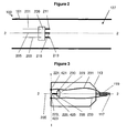
- the aerosol generating system 100 may be a smoking system having a liquid storage portion 113.
- the aerosol generating system 100 of Figure 1 is an electrically heated aerosol generating system 100 and comprises a housing 101 having a mouthpiece end 103 and a body end 105.
- a body end 105 In the body end 105, there is provided an electric power supply in the form of a battery 107 and electric circuitry in the form of circuitry 109 and a puff detection system, not shown.
- a liquid storage portion or cartridge 113 containing liquid 115, a capillary wick 117 and a heating element in the form of a heating coil 119.
- a first end of the capillary wick 117 extends into the cartridge 113 and a second end of the capillary wick 117 is at least partially surrounded by the heating coil 119.
- the heating element 119 may be in close proximity to the capillary wick 117.
- the heating coil 119 is connected to the electric circuitry via connections 121.
- the housing 101 also includes an air inlet 123, an air outlet 125 at the mouthpiece end and a chamber in the form of aerosol forming chamber 127.
- Liquid 115 is transferred by capillary action from the cartridge 113 from one end of the wick 117 which extends from the cartridge to another end of the wick 117 which is surrounded by the heating coil 119.
- the puff detection system senses a puff and activates the heating coil 119.
- the battery 107 supplies electrical energy to the heating coil 119 to heat the end of the wick 117 surrounded by the heating coil.
- the liquid in that end of the wick 117 is vaporized by the heating coil 119 to create a supersaturated vapour.
- the vaporized liquid is replaced by further liquid which is conveyed along the wick 117 by capillary action.
- This process is sometimes referred to as pumping action.
- the supersaturated vapour created is mixed with and carried in the air flow from the air inlet 123.
- the vapour condenses to form an inhalable aerosol, which is carried towards the outlet 125 and into the mouth of the user.
- the circuitry 109 and the puff detection system are preferably programmable.
- the circuitry 109 and puff detection system can be used to manage the device operation. This, in conjunction with the physical design of the electrically heated smoking system, can assist with control of the particle size in the aerosol.
- the capillary wick can be made from a variety of porous or capillary materials and preferably has a known, pre-defined capillarity. Examples include ceramic- or graphite-based materials in the form of fibres or sintered powders. Wicks of different porosities can be used to accommodate different liquid physical properties such as density, viscosity, surface tension and vapour pressure. The capillary properties of the wick should be chosen so that the required amount of liquid can be delivered to portion of the wick adjacent to, or in contact with the heating coil.
- Figure 1 shows an example of an aerosol generating system which may be used with the present invention.
- the aerosol generating system need not be electrically operated.
- a puff detection system need not be provided. Instead, the system may be manually operated, for example, the user may operate a switch to supply electrical energy to the coil when a puff is taken.
- the housing may also comprise a separable shell and mouthpiece. The overall shape and size of the housing may also be altered from that shown in Figure 1 .
- FIG. 2 this shows an enlarged portion of the aerosol generating system 100 of Figure 1 , with the liquid storage portion 113 removed.
- Three electrical connectors 211, 213, 215 are provided.
- the electrical connectors are attached, either directly or indirectly to the housing 101.
- the electrical connectors provide electrical signals to the liquid storage portion 113.
- the electrical connectors shown Figure 2 are mounted in a holder 209. This maintains the relative positions of the connectors, although the holder is optional.
- a first electrically conductive element 201 is electrically connected at a first end to a first end of the first electrical connector 211.
- a second electrically conductive element 203 is electrically connected at a first end to a first end of the second electrical connector 213.
- a third electrically conductive element 205 is electrically connected at a first end to a first end of the third electrical connector 215.
- the electrically conductive elements 201, 203, 205 are electrically connected to the electronic circuitry 109, not shown in Figure 2 .
- the electrically conductive elements 201, 203, 205 and electrical connectors 211, 213, 215 allow electrical signals to pass between the circuitry 109 and liquid storage portion 113.
- the electrically conductive elements 201, 203, 205 are electrically connected to a controller or processor 309 which may be mounted in circuitry 109, not shown in Figure 2 , as well as to a power source 107.
- the electrical connectors 211, 213, 215 and electrically conductive elements 201, 203, 205 may be directly mounted on or within the housing 101, without the need for a holder 209.
- electrical connectors 211, 213, 215 may be directly electrically connected to the controller or processor 309 and power source 107, without the need for electrically conductive elements 201, 203, 205.
- the processor 309 determines whether a liquid storage portion 113 is present in the system 100.
- the processor 309 may also determine what type of liquid storage portion is present in the system.
- the controller or processor 309 also controls when electrical power is provided to the coil 119, and this will be explained in further detail below with reference to Figure 7 .
- the liquid storage portion 113 comprises first, second and third electrical contacts 221 or 421, 223 or 423, 225 or 425 at a first end of the liquid storage portion.
- the first, second and third electrical contacts 221 or 421, 223 or 423, 225 or 425 are physically mounted on the liquid storage portion 113.
- the first electrical contact 221 or 421 is electrically connected to a first end of a first electrically conductive portion 231.
- the second electrical contact 223 or 423 is electrically connected to a first end of a second electrically conductive portion 233.
- a second end of the first electrically conductive portion 231 is electrically connected to a first end of the heating element 119.
- a second end of the second electrically conductive portion 233 is electrically connected to a second end of the heating element 119.
- the electrical contacts 221 or 421, 223 or 423 and electrically conductive portions 231, 233 allow electrical energy to be supplied to the heating element 119 from a battery or other power source, not shown in Figure 2 .
- the battery or power source 107 is usually mounted on or within the aerosol generating system 100.
- a liquid storage portion identification subsystem 229 is mounted on or within the liquid storage portion 113.
- the subsystem may be mounted on the exterior of the liquid storage portion 113 to keep the subsystem and liquid contained within the liquid storage portion 113 separate.
- the subsystem 229 allows the aerosol generating system 100 to detect when a liquid storage portion 113 is present in the housing 101 of the aerosol generating system 100. Further, the subsystem 229 also allows the aerosol generating system 100 to distinguish between different types of liquid storage portions 113 inserted into the aerosol generating system 100. The subsystem 229 is described in further detail below.
- the subsystem 229 is electrically connected to a first end of a third electrically conductive portion 235.
- the second end of the third electrically conductive portion 235 is electrically connected to a third electrical contact 225, 425 on the liquid storage portion 113.
- the subsystem 229 is also electrically connected to the electrically conductive portion 231 with a fourth electrically conductive portion 230, and the purpose of this connection is described below with reference to Figure 7 below.
- the electrically conductive portions 201, 203, 205, 230, 231, 233, 235 may be electrically conductive wire, such as a metallic wire, for example copper wire. Further, the electrically conductive portion may be a conductor of low resistivity, such as copper, or silver, or gold.
- electrical contacts 221, 223, 225 mounted on the liquid storage portion. Further, as previously described, 3 electrical contacts 211, 213, 215, are also provided on the aerosol generating system 100.
- the electrical contacts 211, 213, 215, 221, 223, 225 may be made out of an electrical conductor.
- the conductor may have a low resistivity.
- the conductor may be copper, silver or gold.
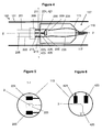
- Figure 4 shows the liquid storage portion 113 of Figure 3 inserted into the aerosol generating system 100 of Figure 2 .
- the electrical contacts 221 or 421, 223 or 423, 225 or 425, on the liquid storage portion 113 are arranged so that they contact corresponding electrical contacts 211, 213, 215, on the aerosol generating system 100 when the liquid storage portion 113 is inserted into the aerosol generating system 100.
- the cartridge or liquid storage portion 113 shown in Figure 4 is contained within the housing 101 of the aerosol generating system 100, however other configurations in which the liquid storage portion 113 is not contained within the housing 101 are possible.
- the liquid storage portion 113 is replaceable.
- the electrical contacts 211, 213, 215 are attached to the aerosol generating system 100 to prevent relative movement of the housing 101 and the electrical contacts 211, 213, 215. Further, the electrical contacts 221, 223, 225 are attached to the to the liquid storage portion 113.
- the liquid storage portion 113 is removed from the aerosol generating system 100, for example by pulling the liquid storage portion 113 and housing 101 in substantially opposite directions such that the liquid storage portion 113 moves away from the aerosol generating system 100, the electrical connection between contacts 221 or 421, 223 or 423, 225 or 425 on the liquid storage portion 113 and the electrical contacts 211, 213, 215 on the aerosol generating system is broken.
- the liquid storage portion 113 is inserted in to the aerosol generating system 100, for example by pushing the liquid storage portion 113 and housing 101 in substantially opposite directions such that the liquid storage portion 113 moves towards the aerosol generating system 100, the electrical connection between contacts 221 or 421, 223 or 423, 225 or 425 on the liquid storage portion 113 and the electrical contacts 211, 213, 215 on the aerosol generating system 100 is made. Therefore, the electrical connection between the liquid storage portion 113 and the aerosol generating is only made when a liquid storage portion 113 is inserted into the aerosol generating system 100.
- the liquid storage portion 113, wick 117, heating element 119, contacts 221, 223, 225, 421, 423, 425 and electrically conductive portions 230, 231, 233, 235, and subsystem 229 may form a single unit which is disposable.
- the unit may also be replaceable.
- Figures 5 and 6 show two alternative arrangements of the electrical contacts 221, 223, 225, 421, 423, 425 on the liquid storage portion 113.
- Figure 5 is a section through line 1-1 in Figure 4 of the drawings.
- Figure 5 shows that the two electrical contacts 221, 223 which are furthest away from the longitudinal axis of symmetry of the liquid storage portion, shown by a dot marked 2 in Figure 5 , are the electrical contacts which provide electrical energy to the heating element 119.
- the electrical contact 225 which is closest to the longitudinal axis of symmetry of the aerosol generating system is the electrical contact which provides the electrical signals to the liquid storage portion recognition subsystem 229.
- the electrical contacts mounted on the aerosol generating system are arranged in a similar arrangement to the electrical contacts mounted on the liquid storage portion 113, shown in Figure 5 . Therefore, the corresponding electrical contacts 211, 213, 215 on the aerosol generating system 100 are also arranged in a row or substantially straight line. In this embodiment, each electrical contact 211, 213, 215 is equidistant from its neighbouring contact.
- the two electrical contacts 211, 213 on the aerosol generating system 100 which are furthest away from the longitudinal axis of symmetry of the aerosol generating system 100, shown by a dotted line marked 2-2 in Figure 4 , are the electrical contacts which provide electrical energy to the heating element 119.
- the electrical contact 215 which is closest to the longitudinal axis of symmetry of the aerosol generating system 100 is the electrical contact which provides the electrical signals to the liquid storage portion recognition subsystem 209.
- the position of the electrical contacts 421, 423, 425 on the liquid storage portion 113 are in the form of a substantially triangular lattice.
- the upper two contacts 421, 423 shown in Figure 6 are electrical contacts which transmit electrical energy to the heating element 119, while the lower contact 425 transmits the electrical signals to the liquid storage portion recognition subsystem 229.
- the spacing of the centre of each contact 421, 423, 425, from the central axis of symmetry, shown by the dot marked 3 in Figure 6 may be equal to each other or equidistant.
- the electrical contacts mounted on the aerosol generating system are arranged in a similar arrangement to the electrical contacts mounted on the liquid storage portion 113 shown in Figure 6 .
- the position of the electrical contacts 211, 213, 215 mounted on the aerosol generating system are also in the form of a substantially triangular lattice.
- the contacts 211, 213 shown in Figure 4 which are furthest away from the longitudinal axis of symmetry shown by the dotted line marked 2-2 in Figure 4 are electrical contacts which transmit electrical energy to the heating element 119, while the contact 215 closest to the longitudinal axis of symmetry shown by the dotted line marked 2-2 transmits the electrical signals to the liquid storage portion recognition subsystem 229.
- the spacing of the centre of each contact 211, 213, 215 from the central axis of symmetry, shown by the dashed line shown 2-2 in Figure 4 may be equal to each other or equidistant.
- Figure 7 shows an electrical circuit diagram of an embodiment of the invention.
- the electrical contacts 211, 213, 215, 221, 223, 225, 421, 423, 425, also shown in Figures 2 to 6 are represented by solid dark circles.
- Figure 7 shows the situation where a liquid storage portion is inserted 113 aerosol generating system 100.
- the components within the enclosure may be replaced each time a liquid storage portion 113 is removed from the aerosol generating system 100 and replaced with a new liquid storage portion 113.
- the components outside the dashed line, as well as the aerosol generating system 100 itself may be reused a number of times with replacement liquid storage portions 113.
- the electrical circuitry of Figure 7 may be divided into 2 separate parts, each of which has a separate function which may be used on its own or in conjunction with one or more of the other parts or other embodiments of the invention.
- One part of the electrical circuitry is a liquid storage portion identification part, and this part comprises two electrical resistors, 504 and 505. Although the resistors 504, 505 shown in Figure 7 are connected in series, other configurations are possible, such as parallel connection. Alternatively, a single electrical resistor may be used.
- embodiments of the invention may also use one or more other electrical components such as one or more capacitors, one or more inductors, one or more diodes or one or more transistors and the like, alternatively or in addition to the resistors 504, 505. This is described in further detail with reference to Figures 10 and 11 below.
- a first terminal of a first resistor 504 is electrically connected to a first terminal of the power source V+ via electrical contacts 211, 221, 421.
- a second terminal of a first resistor 504 is electrically connected to a first terminal of a second resistor 505.
- the second resistor 505 is electrically connected in series with the first resistor 504.
- a second terminal of the second resistor 505 is connected to a controller or processor 309 via electrical contacts 215, 225, 425.
- the electrical contacts 221 or 421, 223 or 423, 225 or 425 on the liquid storage portion 113 come in to physical contact with the electrical contacts 211, 213, 215 on the aerosol generating system 100.
- the controller or processor 309 detects that an electrical circuit has been made because an electrical current can flow through resistors 504, 505. This is because an electrical circuit is made between one terminal of the battery via the resistors 504, 505, and through the controller to the other terminal of the battery which is also connected to the controller.
- the controller 309 is also electrically connected to a negative terminal, V- of a battery or other power source via an electrically conductive element to complete the electrical circuit.
- the aerosol generating device is switched on.
- the controller applies a voltage or potential difference across contacts 211 and 215. Because the resistors 504, 505 are electrically connected to the contacts 225, 425 and contacts 221, 421, the same voltage is also applied across the resistors 504 and 505 assuming that the voltage drop across the contacts is negligible.
- the controller measures the current flow, if any, flowing through the resistors.
- the controller determines whether the current is greater than a predetermined threshold current. If the measured current is greater than a predetermined value, then the controller determines that a liquid storage portion is present, and allows the heater to be energised at step 609.
- the processor determines that a liquid storage portion 113 has been inserted into the aerosol generating system 100. This is advantageous since the aerosol generating system 100 may be de-activated or switched of unless a liquid storage portion is inserted into the aerosol generating system 100. This saves power and also increases the safety of the system.
- the aerosol generating system 100 further comprises a puff detector, although this is not shown in Figure 7 .
- the puff detector may be electrically connected to the controller such that the puff detector feeds an electrical signal into the processor or controller 309 which is indicative of when a user takes a puff.
- the controller 309 may be arranged to only energise the heater if a puff is detected and if the current flow through the resistors 504, 505 is greater than a predetermined threshold current.
- the system may be manually operated.
- the user may operate a switch to supply electrical energy to the heating element 119 when a puff is taken.
- the controller 309 may be arranged to only energise the heater if the user closes a switch and if the current flow through the resistors 504, 505 is greater than a predetermined threshold current.
- the controller 309 is able to distinguish between different liquid storage portions 113 inserted in to the aerosol generating system 100.
- the voltage drop V across a resistor of resistance R is proportional to the product of the resistance R and the current / flowing through the resistor.
- Steps 601, 603, and 605 are the same as those described with reference to Figure 8 , and so will not be described again.
- the controller 309 uses the value of the potential difference applied across the resistors 504 and 505 as well as the measured current flowing through the resistors 504 and 505 to determine the value of the sum of the resistances 504, 505, as previously described.
- the controller 309 determines the liquid storage portion type from the determined resistance value by searching a look-up table using the determined resistance value.
- the look-up table may comprise one or more different resistance values, each resistance value associated with an identifier of a liquid storage portion 113 which can be used with the aerosol generating system.
- the identifier may be indicative of the type of liquid 115 contained within the liquid storage portion 113.
- the controller 309 determines the type of liquid storage portion 113 as the liquid storage portion identifier stored in the look-up table which is associated with the resistance value stored in the look-up table which is closest in value to the liquid storage portion resistance value determined by the controller 309, at step 709.
- the look-up table may be stored in a read only memory (ROM) incorporated into the processor or may be stored in a separate memory store.
- controller 309 is able to distinguish between different types of liquid storage portion 113 inserted into the aerosol generating system 100 in dependence on the determined electrical characteristic or value of the electrical component associated with the liquid storage portion 113.
- the look-up table may further comprise data representing one or more resistance values, each resistance value further associated with parameters representing a different energy profile to be applied to the heating element 119.
- Each resistance value is associated with a different liquid storage portion 113 identifier. This means that the aerosol generating system 100 can be configured to deliver a constant amount, for example volume or mass of aerosol to the user even when liquid storage portions 113 containing different liquids are inserted into the aerosol generating system 100.
- a particular liquid contained within one liquid storage portion 113 may require more energy to vaporise it than a different liquid contained within another liquid storage portion 113.
- a resistance value or a particular liquid storage portion identifier with a heating profile stored in a look-up table, a constant amount of aerosol can be delivered to the user independent of the type of liquid stored in the liquid storage portion 113.
- the controller may perform this additional optional step, shown as step 711 in Figure 9 .
- the controller then applies a particular energy profile to heater 119 in dependence on the determined liquid storage portion type or identifier or independence on the determined characteristic resistance value.
- the resistance values stored in the look-up table may be associated with an optimal voltage and current required by the heating coil to deliver to the user a particular quantity of aerosol for a particular liquid formula.
- the liquid may comprise nicotine.
- the heat of vaporization of this particular liquid formula is different to the heat of vaporization required to vaporize a liquid not containing nicotine.
- the value of one or more electrical components associated with each liquid storage portion allows the controller 309 to determine the liquid storage portion identifier, and hence the type of liquid contained within the liquid storage portion 113. It also allows the controller 309 to deliver the appropriate heating profile to the heating element 119 based on the values stored in the look-up table which are associated with a particular value of electrical component.
- the second portion of the electrical circuitry shown in Figure 7 is a heater circuit part, and this also shows the case when the liquid storage portion 113 is inserted into the aerosol generating system 100.
- the heater circuit comprises the heating element 119, one end of which is electrically connected via contacts 211 or 221, 421 to one terminal V+ of the power source.
- the other end of the heating element 119 is electrically connected via contacts 213 or 223, 423 to a terminal of a transistor 555 or other switch having three terminals.
- the collector terminal of transistor 555 may be connected to the heating element, although other configurations are possible.
- the base terminal of the transistor 555 is electrically connected to the controller 309, while the emitter terminal of the transistor is electrically connected to the other V- terminal of the power source.
- the energy supplied to the heating element 119 is controlled by the current being applied by the controller 309 to the base terminal of the transistor 555. This controls the amount of current flowing from one terminal of the battery via terminals 211 or 221, 421 through the heating coil 119 and through the collector and emitter terminals of transistor 555 via terminals 213 or 223, 423, to the other terminal of the battery.
- one of the terminals of the battery may be a positive electrical voltage, V+, while the other terminal may be a negative electrical voltage, V-.
- V+ positive electrical voltage
- V- negative electrical voltage
- the battery may be any current source such as a capacitor or other power supply.
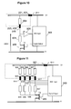
- Figure 10 shows an electrical circuit diagram of an aerosol generating system 100 according an alternative embodiment of the invention.
- features in common with the embodiment shown in Figure 5 have been given like reference numerals.
- the heating element 119 and transistor 555 have not been included in the circuit diagram of Figure 10 .
- the features enclosed within the dashed line are components which are located on or within the liquid storage portion part 113.
- Figure 10 also shows the case when a liquid storage portion 113 is inserted into the aerosol generating system 100.
- the embodiment shown in Figure 10 has 2 electrical contacts 221, 225 or 421, 425 located on or in the liquid storage portion part 113.
- a resistor 804 or other electrical component is mounted on or in the liquid storage portion 113.
- a first terminal of resistor 804 is electrically connected to electrical contact 225, 425 on the liquid storage portion 113.
- a second terminal of resistor 804 is electrically connected to contact 221, 421 on the liquid storage portion 113.
- electrical contact 221 or 421 comes in to contact with electrical contact 211 mounted on the aerosol generating system.
- electrical contact 225 or 425 comes in to contact with electrical contact 215 when the liquid storage portion 113 is inserted into the aerosol generating system 100.
- the electrical contacts 211, 215, 221, 225, 421, 425 allow electrical signals to pass between the liquid storage portion 113 and the rest of the aerosol generating system 100, whilst also allowing the liquid storage portion 113 to be removed and replaced with a new liquid storage portion 113, once the liquid within the storage portion 113 has been depleted.
- One electrical contact 211 on the aerosol generating system 100 is electrically connected by an electrically conductive wire or other conductive means to a positive terminal of a battery or power supply means, V+. This electrical contact 211 is also electrically connected to one input of the micro controller, 309.
- electrical contact 215 is mounted on or in the aerosol generating system 100 and is connected by an electrically conductive means such as a wire to a first terminal of a resistor, 834.
- the electrical contact 215 is also electrically connected to an input of a micro controller 309, such as an analogue to digital converter input of a micro controller 309, via an amplifier 806.
- a second terminal of resistor 834 is electrically connected to a first terminal of a transistor 855.
- a second terminal of transistor 855 is electrically connected to a digital output of micro controller 309.
- a third terminal of transistor 855 is electrically connected to a negative terminal V- of a power supply, battery, capacitor or other means for supplying electrical energy 107.
- the micro controller 309 is also electrically connected to the negative terminal V-of the power supply by an electrically conductive means.
- the aerosol generating system performs the following steps to determine the identifier or type of liquid storage portion 113.
- the digital output of the micro controller 309 is set to a high level.
- the transistor 855 which may be a complimentary metal oxide semiconductor (CMOS) transistor is activated which makes electrical current flow through resistors 804 and 832.
- CMOS complimentary metal oxide semiconductor
- the voltage amplitude of voltage V834 is sufficiently large that an amplifier 806 is not needed.
- the voltage across resistor 834 is input into an analog to digital conversion input of the microcontroller 309.
- the controller determines the value R804 of resistor 804 using one of the above equations. Then, the thus determined resistance value is then compared to a set of resistance values stored in a memory such as a read only memory.
- the microcontroller 309 determines if the determined resistance value corresponds to or matches a resistance value located in a memory space of the memory. If the values match, then a stored heating element profile, which is associated with the resistance value in the memory matching the determined resistance value is used to energize the heating element 119.
- the aerosol generating system 100 determines the value R804 of resistor 804. It then compares this value to a database of resistor values. Each resistor value is associated with a different heating profile. The processor then selects the heating profile associated with the resistor value in the database which corresponds to, or matches the determined value of resistor 804.
- the heating profile may be defined by a number of different operational parameters for the heating element.
- Figure 11 shows an electrical circuit diagram of an aerosol generating system 100 according yet a further embodiment of the invention. This diagram shows the case when a liquid storage portion 113 is inserted into the aerosol generating system 100.
- each resistor is located on or in the liquid storage portion 113.
- a first terminal of each resistor is electrically connected to electrical contact 921.
- electrical contact 921 comes into electrical contact with a contact 911 mounted on or in the aerosol generating system 100.
- Contact 911 is electrically connected both to a positive voltage V+ of a power supply means 107 and to a micro controller 309.
- a second terminal of each resistor 904, 905, 906, 907 is electrically connected to connectors 924, 925, 926, 927. Each second terminal of each resistor is electrically connected to one of the connectors 924, 925, 926, 927. Each second terminal of each resistor 904, 905, 906, 907 is electrically connected to a different connector 924, 925, 926, 927. That is to say, each second terminal of each resistor 904, 905, 906, 907 is electrically connected only to one of the connectors 924, 925, 926, 927.
- each of the resistors 934, 935, 936, 937 is electrically connected to connectors 914, 915, 916, 917 on the aerosol generating system.
- Each first terminal of each resistor 934, 935, 936, 937 is electrically connected to one of the connectors 914, 915, 916, 917.
- Each first terminal of each resistor 934, 935, 936, 937 is electrically connected to a different connector 914, 915, 916, 917 on the aerosol generating system 100. That is to say, each first terminal of each resistor 934, 935, 936, 937 is electrically connected to only one of the connectors 914, 915, 916, 917.
- each first terminal of each resistor 934, 935, 936, 937 is separately electrically connected to a controller 309.
- Each second terminal of each resistor 934, 935, 936, 937 is electrically connected to one terminal of transistor or switch 955 having 3 terminals. Each second resistor terminal is connected to the same transistor terminal.
- a second terminal of transistor 955 is electrically connected to a digital output of controller 309.
- a third terminal of transistor 955 is electrically connected to a negative voltage supply V-.
- the controller 309 is also electrically connected to the negative voltage supply V-.
- the processor 309 determines the value of each of the resistors 904, 905, 906, 907 using this equation, in a similar manner as previously described with reference to Figure 10 .
- the controller may determine that the resistors (904, 905, 906, 907) have values of (1k ⁇ , 2k ⁇ , 5k ⁇ , 10k ⁇ ). This is referred to a resistor network code of (1, 2, 5, 10).
- the resistor network code is used to deliver a heating profile and the consumable type to the microcontroller. Therefore it does not require comparing the determined resistor values to stored resistor values associated with a heating profile.
- the analog signals present at the analog to digital conversion ports are directly used to generate the heating profile.
- the determined value of each of the resistors 904, 905, 906, 907 is used as a direct input to calculate the appropriate heating profile characteristics.
- the heating profile may be defined by a number of different operational parameters for the heating element.
- the processor 309 uses the determined value of each resistor 904, 905, 906, 907 to directly calculate the value of each operational parameter which the processor applies to the heating element. This has the advantage that a look-up table is not required to determine what heating profile should be applied to a particular liquid storage portion since the processor 309 determines the values to be applied to the heating element based on the determined resistor values.
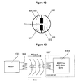
- Figure 12 shows a liquid storage portion 113 according to the embodiment of the invention described with reference to Figure 11 .
- the electrical contacts 921, 923, 924, 925, 926, 927 on the liquid storage portion 113 are arranged in a substantially rectangular or square lattice.
- Figure 12 shows that the two electrical contacts 921, 923 which are closest to the central longitudinal axis of symmetry of the liquid storage portion, shown by a dot marked 12 in Figure 12 , are the electrical contacts which provide electrical energy to the heating element 119.
- the electrical contacts 924, 925, 926, 927, which are furthest away from the longitudinal axis of symmetry of the aerosol generating system 100 are the electrical contacts which provides the electrical signals to the liquid storage portion recognition subsystem 229.
- the electrical contacts mounted on the aerosol generating system are arranged in a similar arrangement to the electrical contacts mounted on the liquid storage portion, shown in Figure 12 , and so will not be described again in further detail.
- Figure 13 is a schematic diagram of selected components of a further aerosol generating system embodying the invention.
- a radio frequency identification (RFID) chip 1301 is located on or within the liquid storage portion.
- the chip may comprise an antenna 1307 electrically coupled to the chip.
- the chip 1301 and antenna 1307 may be incorporated into a single tag which may be applied by adhesive or other means to the liquid storage portion.
- the chip contains a flash memory or an Electrically Erasable Programmable Read Only Memory (EEPROM) in which data such as one or more of a liquid former identification i.e. the liquid contained within the liquid storage portion 113, a cartridge serial number, and a heating profile for the liquid former.
- EEPROM Electrically Erasable Programmable Read Only Memory
- the aerosol generating system comprises an interrogator 1303 and an antenna 1305 electrically coupled to the interrogator.
- the interrogator 1303 and antenna 1305 may be integrated into a single processor 309 for controlling operation of the aerosol generating system 100.
- the interrogator 1303 and antenna 1305 may be separate from the processor 309.
- the interrogator 1303, located on or within the aerosol generating system 100 energizes the RFID chip 1301 via antenna 1307 with a radio frequency (RF) signal emitted from the antenna 1305.
- RF radio frequency
- the data from the chip are then transmitted by frequency modulation emitted from the antenna 1307 located on the chip 1301 to the interrogator 1303 via the antenna 1305.
- the data may be stored in a memory.
- the data received from the chip 1301 may comprise a liquid storage portion identifier and optionally one or more operational parameters of the heating element which the system may use to energize the heating element, or an identifier of the type of liquid contained within the liquid storage portion.
- the liquid storage portion identifier may be a unique identifier.
- the controller 309 may examine the data to determine the liquid storage portion type being used with the aerosol generating system. Therefore, the controller can distinguish between different liquid storage portions.
- the controller 309 may apply a particular energy profile to heater 119 in dependence on the determined liquid storage portion type or identifier.
- the data received by the system 100 may be optimal heating element operating parameters to deliver to the user a particular quantity of aerosol for a particular liquid formula.
- the liquid may comprise nicotine.
- the heat of vaporization of this particular liquid formula is different to the heat of vaporization required to vaporize a liquid not containing nicotine.
- the data encoded in a chip 1301 associated with each liquid storage portion 113 allows the controller 309 to determine the liquid storage portion identifier, and hence the type of liquid contained within the liquid storage portion 113. It also allows the controller 309 to deliver the appropriate heating profile to the heating element 119 based on the data received from the chip associated with each liquid storage portion 113.
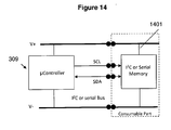
- Figure 14 shows a schematic diagram of selected components of an aerosol generating system 100 embodying the invention.
- Data such as data identifying a liquid storage portion 113 is stored on a memory on or in the liquid storage portion.
- data is transferred between a controller 309 and memory 1401 using an 12C bus although other data transmission protocols are possible.
- the memory 1401 is powered by electrically connecting the memory 1401 with an electrically conductive portion to one terminal of a power supply, such as a positive voltage, V+.
- the memory is also electrically connected with an electrically conductive portion to another terminal of a power supply, such as a negative voltage, V-.
- the memory is also electrically connected to the controller 309 via a clock line, SCL, so synchronise data transfer over the data line.
- the memory is further electrically connected to the controller 309 via a data line, SDA, which allows data to be transferred between the memory 1401 and the controller 309.
- the data stored on the memory 1401 may comprise information enabling the system 100 to distinguish between different liquid storage portions.
- the data may comprise operational parameters for the heating element of the smoking system which have been optimised for the particular liquid contained within the liquid storage portion 113.
- the data is encoded on a Programmable Read Only Memory or Flash Memory located on or in the liquid storage portion.
- the data for a particular liquid storage portion such as a heating profile, product identification or liquid storage portion identifier are stored in a flash or Erasable Programmable Read Only Memory (EPROM) memory 1401 located on or within the liquid storage portion 1301
- EPROM Erasable Programmable Read Only Memory
- the microcontroller 309 interrogates the memory 1401 via a serial communication bus using an 12C communication protocol or another serial data transfer protocol. If the data stored in cartridge present the correct format or the correct information is present, the data stored in the memory will then further be used when the aerosol generating device is used.
- This embodiment has the advantage that only 2 physical connections with the device, shown as solid dark circles in figure 14 , in addition to the two power connections shown in solid dark circles in Figure 14 are required for supplying electrical power to the memory 1401.
- the data encoded in the memory 1401 associated with each liquid storage portion allows the controller 309 to receive data from the memory 1401 and determine the liquid storage portion identifier, and hence the type of liquid contained within the liquid storage portion 113. It also allows the controller 309 to deliver the appropriate heating profile to the heating element 119 based on the data received from the memory 1401 associated with each liquid storage portion.
- the heating profile may be defined by a number of different operational parameters for the heating element.
- a 3-dimensional shape including one or more bumps, protuberances, hollows, or furrows may be formed in the liquid storage portion, or attached to the exterior or other surface of the liquid storage portion 113.
- the aerosol generating system 100 includes one or more switches which are engaged by the 3-dimensional shape comprising one or more bumps on the liquid storage portion.
- the particular position on the liquid storage of the bumps, protuberances, hollows, or furrows or hollows may determine whether one or more of the switches is activated.
- the position of the bumps or hollows on the liquid storage portion therefore allows information about the liquid storage portion to be encoded into or onto the liquid storage portion in the form of a 3-dimensional shape. Therefore, the 3-dimentionsal shape associated with each liquid storage portion allows the controller 309 to determine the liquid storage portion identifier, and hence the type of liquid contained within the liquid storage portion 113. It also allows the controller 309 to deliver the appropriate heating profiled to the heating element based on the date decoded from the shape associated with each liquid storage portion 113.
Priority Applications (4)
| Application Number | Priority Date | Filing Date | Title |
|---|---|---|---|
| EP10251135A EP2399636A1 (fr) | 2010-06-23 | 2010-06-23 | Générateur d'aérosol amélioré et partie de stockage de liquide pour une utilisation avec le générateur d'aérosol |
| PCT/EP2011/002952 WO2011160788A1 (fr) | 2010-06-23 | 2011-06-15 | Générateur aérosol amélioré et partie de stockage de liquide à utiliser avec le générateur aérosol |
| TW100121536A TW201206357A (en) | 2010-06-23 | 2011-06-21 | An improved aerosol generator and liquid storage portion for use with the aerosol generator |
| ARP110102153A AR082377A1 (es) | 2010-06-23 | 2011-06-22 | Un generador de aerosol mejorado y una parte para el almacenamiento de liquidos que se utiliza con el generador de aerosol |
Applications Claiming Priority (1)
| Application Number | Priority Date | Filing Date | Title |
|---|---|---|---|
| EP10251135A EP2399636A1 (fr) | 2010-06-23 | 2010-06-23 | Générateur d'aérosol amélioré et partie de stockage de liquide pour une utilisation avec le générateur d'aérosol |
Publications (1)
| Publication Number | Publication Date |
|---|---|
| EP2399636A1 true EP2399636A1 (fr) | 2011-12-28 |
Family
ID=42732465
Family Applications (1)
| Application Number | Title | Priority Date | Filing Date |
|---|---|---|---|
| EP10251135A Withdrawn EP2399636A1 (fr) | 2010-06-23 | 2010-06-23 | Générateur d'aérosol amélioré et partie de stockage de liquide pour une utilisation avec le générateur d'aérosol |
Country Status (4)
| Country | Link |
|---|---|
| EP (1) | EP2399636A1 (fr) |
| AR (1) | AR082377A1 (fr) |
| TW (1) | TW201206357A (fr) |
| WO (1) | WO2011160788A1 (fr) |
Cited By (96)
| Publication number | Priority date | Publication date | Assignee | Title |
|---|---|---|---|---|
| WO2013112459A1 (fr) * | 2012-01-27 | 2013-08-01 | Intelligent Energy Limited | Vérification de clé de cartouches de combustible remplaçables |
| CN103379836A (zh) * | 2012-01-25 | 2013-10-30 | 中汇远东实业有限公司 | 一种电子仿真烟及其雾化器 |
| CN103826480A (zh) * | 2012-01-24 | 2014-05-28 | 中汇远东实业有限公司 | 一种电子仿真烟及其仿真烟嘴 |
| WO2014085999A1 (fr) * | 2012-12-05 | 2014-06-12 | Liu Qiuming | Cigarette électronique à raccordement magnétique ayant un raccord |
| WO2015022448A1 (fr) | 2013-08-14 | 2015-02-19 | Pixan Oy | Appareil et procédé de commande d'un vaporisateur électrique |
| KR20150064754A (ko) * | 2012-10-08 | 2015-06-11 | 아아르. 제이. 레날드즈 토바코 캄파니 | 전자 흡연 물품 및 관련 방법 |
| WO2014203083A3 (fr) * | 2013-05-20 | 2015-08-06 | Sis Resources, Ltd. | Prévision de combustion et communications pour une cigarette électronique |
| DE102014005730A1 (de) * | 2014-04-17 | 2015-10-22 | Steamo Gmbh | Verfahren zur Übermittlung und/oder zum Abgleich der Betriebsparameter der Steuereinrichtung einer elektrischen Zigarette |
| WO2015110924A3 (fr) * | 2014-01-27 | 2015-12-17 | Sis Resources Ltd. | Communication filaire dans un dispositif de vapotage |
| WO2016005602A1 (fr) * | 2014-07-11 | 2016-01-14 | Philip Morris Products S.A. | Système de génération d'aérosol comprenant une détection de cartouche |
| EP2875740A3 (fr) * | 2013-11-12 | 2016-05-04 | VMR Products, LLC | Vaporisateur |
| WO2016092259A1 (fr) * | 2014-12-11 | 2016-06-16 | Nicoventures Holdings Limited | Système électronique de fourniture de vapeur |
| WO2016096482A1 (fr) * | 2014-12-15 | 2016-06-23 | Philip Morris Products S.A. | Procédé de commande de production d'aérosol pour commander des propriétés d'aérosol |
| WO2016123805A1 (fr) * | 2015-02-06 | 2016-08-11 | 昂纳自动化技术(深圳)有限公司 | Atomiseur de cigarette électronique |
| CN106068084A (zh) * | 2014-03-19 | 2016-11-02 | 菲利普莫里斯生产公司 | 包括相互缠绕的芯子和加热元件的气溶胶生成装置 |
| US20170020191A1 (en) * | 2015-07-24 | 2017-01-26 | R. J. Reynolds Tobacco Company | Radio-frequency identification (rfid) authentication system for aerosol delivery devices |
| US20170042236A1 (en) | 2014-02-28 | 2017-02-16 | Beyond Twenty Ltd. | Electronic vaporiser system |
| CN106418702A (zh) * | 2016-09-06 | 2017-02-22 | 深圳市合元科技有限公司 | 一种电子烟及其温度控制方法和装置 |
| EP3135135A1 (fr) * | 2015-08-28 | 2017-03-01 | Fontem Holdings 1 B.V. | Dispositif à fumer électronique avec réservoir de liquide/partie de mèche |
| GB2542926A (en) * | 2014-02-28 | 2017-04-05 | Beyond Twenty Ltd | Electronic vaporiser system |
| WO2017084849A1 (fr) | 2015-11-17 | 2017-05-26 | Philip Morris Products S.A. | Cartouche pour un système de production d'aérosol avec résistance d'identification personnalisable |
| WO2017084848A1 (fr) | 2015-11-17 | 2017-05-26 | Philip Morris Products S.A. | Cartouche pour un système de production d'aérosol avec inducteur d'identification |
| WO2017137510A1 (fr) * | 2016-02-12 | 2017-08-17 | Philip Morris Products S.A. | Système de génération d'aérosol ayant une identification de substrat de formation d'aérosol liquide |
| WO2017137512A1 (fr) * | 2016-02-12 | 2017-08-17 | Philip Morris Products S.A. | Système de production d'aérosol avec détecteur de bouffée |
| US20170231277A1 (en) * | 2016-02-12 | 2017-08-17 | Oleg Mironov | Aerosol-generating system with liquid aerosol-forming substrate identification |
| EP3248482A1 (fr) * | 2016-05-27 | 2017-11-29 | Shenzhen First Union Technology Co., Ltd. | Cigarette électronique et son procédé d'utilisation |
| WO2017205692A1 (fr) * | 2016-05-25 | 2017-11-30 | Pax Labs, Inc. | Commande d'un vaporisateur électronique |
| CN107647478A (zh) * | 2016-07-25 | 2018-02-02 | 富特姆1有限公司 | 控制电子香烟的操作 |
| DE102016114718A1 (de) * | 2016-08-09 | 2018-02-15 | Hauni Maschinenbau Gmbh | Inhalator und Flüssigkeitsspeicher für einen Inhalator |
| WO2018083007A1 (fr) * | 2016-11-01 | 2018-05-11 | Hauni Maschinenbau Gmbh | Unité d'évaporation pour un inhalateur et procédé de commande d'une unité d'évaporation |
| US10034988B2 (en) | 2012-11-28 | 2018-07-31 | Fontem Holdings I B.V. | Methods and devices for compound delivery |
| USD825102S1 (en) | 2016-07-28 | 2018-08-07 | Juul Labs, Inc. | Vaporizer device with cartridge |
| US10045567B2 (en) | 2013-12-23 | 2018-08-14 | Juul Labs, Inc. | Vaporization device systems and methods |
| US10045565B2 (en) | 2014-02-28 | 2018-08-14 | Beyond Twenty Ltd. | E-cigarette personal vaporizer |
| US10045568B2 (en) | 2013-12-23 | 2018-08-14 | Juul Labs, Inc. | Vaporization device systems and methods |
| US10058130B2 (en) | 2013-12-23 | 2018-08-28 | Juul Labs, Inc. | Cartridge for use with a vaporizer device |
| US10076139B2 (en) | 2013-12-23 | 2018-09-18 | Juul Labs, Inc. | Vaporizer apparatus |
| US10091839B2 (en) | 2014-02-28 | 2018-10-02 | Beyond Twenty Ltd. | Electronic vaporiser system |
| US10104915B2 (en) | 2013-12-23 | 2018-10-23 | Juul Labs, Inc. | Securely attaching cartridges for vaporizer devices |
| US10111470B2 (en) | 2013-12-23 | 2018-10-30 | Juul Labs, Inc. | Vaporizer apparatus |
| WO2018202727A1 (fr) * | 2017-05-02 | 2018-11-08 | Philip Morris Products S.A. | Ensemble chauffage pour un système de production d'aérosol |
| US10136674B2 (en) | 2014-02-28 | 2018-11-27 | Beyond Twenty Ltd. | Electronic vaporiser system |
| USD836541S1 (en) | 2016-06-23 | 2018-12-25 | Pax Labs, Inc. | Charging device |
| US10194693B2 (en) | 2013-09-20 | 2019-02-05 | Fontem Holdings 1 B.V. | Aerosol generating device |
| USD842536S1 (en) | 2016-07-28 | 2019-03-05 | Juul Labs, Inc. | Vaporizer cartridge |
| WO2019048211A1 (fr) * | 2017-09-08 | 2019-03-14 | Philip Morris Products S.A. | Identification de consommable |
| US10244793B2 (en) | 2005-07-19 | 2019-04-02 | Juul Labs, Inc. | Devices for vaporization of a substance |
| USD848057S1 (en) | 2016-06-23 | 2019-05-07 | Pax Labs, Inc. | Lid for a vaporizer |
| US10279934B2 (en) | 2013-03-15 | 2019-05-07 | Juul Labs, Inc. | Fillable vaporizer cartridge and method of filling |
| US10285449B2 (en) | 2015-09-01 | 2019-05-14 | Ayr Ltd. | Electronic vaporiser system |
| USD849996S1 (en) | 2016-06-16 | 2019-05-28 | Pax Labs, Inc. | Vaporizer cartridge |
| EP2870888B1 (fr) | 2010-12-24 | 2019-05-29 | Philip Morris Products S.A. | Système de génération d'aérosol doté de moyens pour désactiver un consommable |
| USD851830S1 (en) | 2016-06-23 | 2019-06-18 | Pax Labs, Inc. | Combined vaporizer tamp and pick tool |
| WO2019146063A1 (fr) | 2018-01-26 | 2019-08-01 | 日本たばこ産業株式会社 | Dispositif de production d'aérosol et procédé et programme d'actionnement associés |
| WO2019146061A1 (fr) | 2018-01-26 | 2019-08-01 | 日本たばこ産業株式会社 | Dispositif de génération d'aérosol, et procédé et programme pour le faire fonctionner |
| WO2019146062A1 (fr) | 2018-01-26 | 2019-08-01 | 日本たばこ産業株式会社 | Dispositif de génération d'aérosol et procédé de production d'un dispositif de génération d'aérosol |
| CN110101126A (zh) * | 2013-11-12 | 2019-08-09 | Vmr产品有限责任公司 | 蒸发器、充电器及其使用方法 |
| CN110169598A (zh) * | 2019-05-14 | 2019-08-27 | 筑思有限公司 | 电子烟、烟具和烟弹 |
| US10405582B2 (en) | 2016-03-10 | 2019-09-10 | Pax Labs, Inc. | Vaporization device with lip sensing |
| WO2019185746A1 (fr) * | 2018-03-29 | 2019-10-03 | Nicoventures Trading Limited | Dispositif de distribution d'aérosol, article pour une utilisation avec celui-ci, et procédé d'identification d'un article |
| WO2019186150A1 (fr) * | 2018-03-29 | 2019-10-03 | Nicoventures Trading Limited | Système de production de vapeur doté d'une détection de partie de transport de matériau de substrat aérosolisable |
| WO2019185715A1 (fr) * | 2018-03-29 | 2019-10-03 | Nicoventures Trading Limited | Dispositif de génération d'aérosol |
| US10512282B2 (en) | 2014-12-05 | 2019-12-24 | Juul Labs, Inc. | Calibrated dose control |
| US10575561B2 (en) | 2015-11-17 | 2020-03-03 | Altria Client Services Llc | Cartridge for an aerosol-generating system with customizable identification resistance |
| US10588176B2 (en) | 2014-02-28 | 2020-03-10 | Ayr Ltd. | Electronic vaporiser system |
| EP3512369A4 (fr) * | 2016-09-14 | 2020-05-13 | Altria Client Services LLC | Dispositif pour fumer |
| US10674764B2 (en) | 2015-11-17 | 2020-06-09 | Altria Client Services Llc | Cartridge for an aerosol-generating system with identification inductor |
| USD887632S1 (en) | 2017-09-14 | 2020-06-16 | Pax Labs, Inc. | Vaporizer cartridge |
| US10687555B2 (en) | 2014-06-27 | 2020-06-23 | Batmark Limited | Vaporizer assembly having a vaporizer and a matrix |
| US10709173B2 (en) | 2014-02-06 | 2020-07-14 | Juul Labs, Inc. | Vaporizer apparatus |
| EP3698662A1 (fr) * | 2019-02-19 | 2020-08-26 | Nerudia Ltd. | Dispositif de substitution du tabac |
| US10757976B2 (en) | 2016-02-12 | 2020-09-01 | Altria Client Services Llc | Aerosol-generating system with puff detector |
| US10834967B2 (en) | 2016-12-27 | 2020-11-17 | Gofire, Inc. | System and method for managing concentrate usage of a user |
| US10865001B2 (en) | 2016-02-11 | 2020-12-15 | Juul Labs, Inc. | Fillable vaporizer cartridge and method of filling |
| EP3245886B1 (fr) | 2014-11-11 | 2020-12-30 | JT International SA | Inhalateurs de vapeur électroniques |
| US10881150B2 (en) | 2012-10-08 | 2021-01-05 | Rai Strategic Holdings, Inc. | Aerosol delivery device |
| US10888665B2 (en) | 2019-01-02 | 2021-01-12 | Gofire, Inc. | System and method for multi-modal dosing device |
| EP3305105B1 (fr) | 2012-05-14 | 2021-01-13 | Nicoventures Trading Limited | Dispositif de fourniture de vapeur électronique |
| US10912333B2 (en) | 2016-02-25 | 2021-02-09 | Juul Labs, Inc. | Vaporization device control systems and methods |
| EP3357356B1 (fr) | 2012-05-14 | 2021-02-17 | Nicoventures Trading Limited | Dispositif de fourniture de vapeur électronique |
| EP3432957B1 (fr) | 2016-03-24 | 2021-03-10 | Nicoventures Trading Limited | Système électronique de fourniture de vapeur |
| US10986875B2 (en) | 2018-06-25 | 2021-04-27 | Juul Labs, Inc. | Vaporizer device heater control |
| US11006668B2 (en) * | 2016-02-12 | 2021-05-18 | Altria Client Services Llc | Aerosol-generating system with electrodes |
| US11019685B2 (en) | 2014-02-06 | 2021-05-25 | Juul Labs, Inc. | Vaporization device systems and methods |
| EP3677132A4 (fr) * | 2017-08-30 | 2021-06-09 | Joyetech Europe Holding GmbH | Procédé de commande de cigarette électronique et cigarette électronique |
| EP3841896A1 (fr) * | 2019-12-24 | 2021-06-30 | Shenzhen Smoore Technology Limited | Pôle de batterie et dispositif d'atomisation électronique |
| US11064741B2 (en) | 2016-02-09 | 2021-07-20 | Altria Client Services Llc | Element for an electrically operated aerosol-generating system having a dual function |
| US11085550B2 (en) | 2014-02-28 | 2021-08-10 | Ayr Ltd. | Electronic vaporiser system |
| WO2021156604A1 (fr) * | 2020-02-07 | 2021-08-12 | Nicoventures Trading Limited | Système de fourniture d'aérosol |
| EP4011225A1 (fr) * | 2016-07-06 | 2022-06-15 | RAI Strategic Holdings, Inc. | Dispositif d'administration d'aérosol doté d'un boîtier de réservoir et d'un ensemble vaporisateur |
| USRE49114E1 (en) | 2011-06-28 | 2022-06-28 | Juul Labs, Inc. | Electronic cigarette with liquid reservoir |
| US11428738B2 (en) | 2013-03-07 | 2022-08-30 | Rai Strategic Holdings, Inc. | Aerosol delivery device |
| RU2782783C2 (ru) * | 2017-09-08 | 2022-11-02 | Филип Моррис Продактс С.А. | Идентификация расходной части |
| EP3260000B1 (fr) | 2015-03-10 | 2023-01-04 | Japan Tobacco Inc. | Procédé de production d'une unité d'atomisation |
| WO2023186596A1 (fr) * | 2022-04-01 | 2023-10-05 | Jt International Sa | Systèmes de génération de vapeur |
| US11871484B2 (en) | 2013-03-15 | 2024-01-09 | Rai Strategic Holdings, Inc. | Aerosol delivery device |
Families Citing this family (35)
| Publication number | Priority date | Publication date | Assignee | Title |
|---|---|---|---|---|
| GB2504075A (en) | 2012-07-16 | 2014-01-22 | Nicoventures Holdings Ltd | Electronic smoking device |
| GB2504076A (en) * | 2012-07-16 | 2014-01-22 | Nicoventures Holdings Ltd | Electronic smoking device |
| GB2504077A (en) | 2012-07-16 | 2014-01-22 | Nicoventures Holdings Ltd | Electronic smoking device |
| US20140261487A1 (en) * | 2013-03-14 | 2014-09-18 | R. J. Reynolds Tobacco Company | Electronic smoking article with improved storage and transport of aerosol precursor compositions |
| WO2014150979A2 (fr) * | 2013-03-15 | 2014-09-25 | R. J. Reynolds Tobacco Company | Eléments chauffants formés à partir d'une feuille de matériau, entrées et procédés pour la production de pulvérisateurs, cartouche pour un dispositif de distribution d'aérosol et procédé pour assembler une cartouche pour un article à fumer |
| SG11201508669UA (en) | 2013-05-21 | 2015-11-27 | Philip Morris Products Sa | Aerosol comprising distributing agent and a medicament source |
| BR112015032001B1 (pt) * | 2013-06-19 | 2022-04-26 | Fontem Holdings 4 B.V. | Cigarro eletrônico |
| US11229239B2 (en) | 2013-07-19 | 2022-01-25 | Rai Strategic Holdings, Inc. | Electronic smoking article with haptic feedback |
| WO2015082560A1 (fr) | 2013-12-03 | 2015-06-11 | Philip Morris Products S.A. | Article de génération d'aérosol, et système actionné électriquement incorporant un traceur |
| TWI697289B (zh) * | 2014-05-21 | 2020-07-01 | 瑞士商菲利浦莫里斯製品股份有限公司 | 氣溶膠形成製品、電熱氣溶膠產生裝置及系統、及操作該系統之方法 |
| CN112189901A (zh) | 2014-05-21 | 2021-01-08 | 菲利普莫里斯生产公司 | 具有内部感受器的气溶胶生成制品 |
| PL3247235T3 (pl) | 2015-01-22 | 2021-04-06 | Fontem Holdings 1 B.V. | Elektroniczne urządzenia odparowujące |
| GB201503411D0 (en) | 2015-02-27 | 2015-04-15 | British American Tobacco Co | Apparatus and method for generating an inhalable medium, and a cartridge for use therewith |
| GB201505595D0 (en) | 2015-03-31 | 2015-05-13 | British American Tobacco Co | Cartridge for use with apparatus for heating smokeable material |
| GB201505593D0 (en) | 2015-03-31 | 2015-05-13 | British American Tobacco Co | Article for use with apparatus for heating smokable material |
| TWI674072B (zh) * | 2015-04-30 | 2019-10-11 | 日商日本煙草產業股份有限公司 | 非燃燒型香味吸嘗器 |
| EP3272382B1 (fr) | 2015-04-30 | 2020-09-02 | Japan Tobacco Inc. | Appareil d'aspiration d'arôme sans combustion |
| TWI638609B (zh) | 2015-05-22 | 2018-10-21 | 日本煙草產業股份有限公司 | 霧化單元的製造方法、霧化單元及非燃燒型香味吸嚐器 |
| WO2016190222A1 (fr) | 2015-05-22 | 2016-12-01 | 日本たばこ産業株式会社 | Procédé de fabrication d'unité d'atomisation, unité d'atomisation, et aspirateur à parfum de type sans combustion |
| US10492528B2 (en) | 2015-08-11 | 2019-12-03 | Altria Client Services Llc | Power supply section configuration for an electronic vaping device and electronic vaping device |
| CA2999214A1 (fr) * | 2015-09-24 | 2017-03-30 | Philip Morris Products S.A. | Article de generation d'aerosol pourvu d'un condensateur |
| CA2999207A1 (fr) * | 2015-09-24 | 2017-03-30 | Philip Morris Products S.A. | Dispositif de generation d'aerosol a electrodes pour mesurer une charge electrique |
| RU2706836C2 (ru) | 2015-09-24 | 2019-11-21 | Филип Моррис Продактс С.А. | Образующая аэрозоль система с конденсатором |
| CN107874319B (zh) * | 2016-09-30 | 2020-11-03 | 卓尔悦欧洲控股有限公司 | 电子烟及其电源结构 |
| GB201618481D0 (en) | 2016-11-02 | 2016-12-14 | British American Tobacco Investments Ltd | Aerosol provision article |
| CN109982587B (zh) * | 2016-12-19 | 2022-06-24 | 菲利普莫里斯生产公司 | 包括多种气溶胶形成基质和液体传送元件的气溶胶生成系统 |
| US10575562B2 (en) * | 2017-06-30 | 2020-03-03 | Rai Strategic Holdings, Inc. | Smoking article for identifying an attribute of an aerosol-generating element for adaptive power output and an associated method |
| GB201805169D0 (en) * | 2018-03-29 | 2018-05-16 | Nicoventures Holdings Ltd | A control device for an electronic aerosol provision system |
| GB201805168D0 (en) * | 2018-03-29 | 2018-05-16 | Nicoventures Holdings Ltd | A control device for an electronic aerosol provision system |
| GB201805170D0 (en) * | 2018-03-29 | 2018-05-16 | Nicoventures Holdings Ltd | Electronic aerosol provision system |
| GB201805266D0 (en) * | 2018-03-29 | 2018-05-16 | Nicoventures Trading Ltd | Apparatus for generating aerosol from an aerosolisable medium and article of aerosolisable medium |
| GB201812372D0 (en) * | 2018-07-30 | 2018-09-12 | Nicoventures Trading Ltd | Tobacco blend |
| US11413409B2 (en) | 2018-09-12 | 2022-08-16 | Juul Labs, Inc. | Vaporizer including positive temperature coefficient of resistivity (PTCR) heating element |
| US20220039478A1 (en) * | 2018-12-17 | 2022-02-10 | Philip Morris Products S.A. | Aerosol-generating device with mouthpiece detection |
| JP6522225B2 (ja) * | 2018-12-19 | 2019-05-29 | 日本たばこ産業株式会社 | 霧化ユニットの製造方法、非燃焼型香味吸引器、霧化ユニット及び霧化ユニットパッケージ |
Citations (7)
| Publication number | Priority date | Publication date | Assignee | Title |
|---|---|---|---|---|
| WO2003059424A1 (fr) * | 2002-01-15 | 2003-07-24 | Aerogen, Inc. | Procedes et systemes de fonctionnement d'un generateur d'aerosol |
| WO2005025654A1 (fr) * | 2003-09-16 | 2005-03-24 | Injet Digital Aerosols Limited | Inhalateur a regulation d'ecoulement d'air |
| US20060118612A1 (en) * | 2003-03-24 | 2006-06-08 | Novo Nordisk A/S | Electronic marking of a medication cartridge |
| WO2006084543A1 (fr) * | 2005-02-11 | 2006-08-17 | Pari Pharma Gmbh | Dispositif de traitement par inhalation et procede pour faire fonctionner ce dernier |
| EP1772166A1 (fr) * | 2005-10-04 | 2007-04-11 | Canon Kabushiki Kaisha | Appareil pour éjecter un liquide |
| WO2007078273A1 (fr) | 2005-12-22 | 2007-07-12 | Augite Incorporation | Appareil electronique pour fumer sans goudron |
| US20090095287A1 (en) * | 2007-10-15 | 2009-04-16 | Hamid Emarlou | Method and system for vaporization of a substance |
-
2010
- 2010-06-23 EP EP10251135A patent/EP2399636A1/fr not_active Withdrawn
-
2011
- 2011-06-15 WO PCT/EP2011/002952 patent/WO2011160788A1/fr active Application Filing
- 2011-06-21 TW TW100121536A patent/TW201206357A/zh unknown
- 2011-06-22 AR ARP110102153A patent/AR082377A1/es unknown
Patent Citations (7)
| Publication number | Priority date | Publication date | Assignee | Title |
|---|---|---|---|---|
| WO2003059424A1 (fr) * | 2002-01-15 | 2003-07-24 | Aerogen, Inc. | Procedes et systemes de fonctionnement d'un generateur d'aerosol |
| US20060118612A1 (en) * | 2003-03-24 | 2006-06-08 | Novo Nordisk A/S | Electronic marking of a medication cartridge |
| WO2005025654A1 (fr) * | 2003-09-16 | 2005-03-24 | Injet Digital Aerosols Limited | Inhalateur a regulation d'ecoulement d'air |
| WO2006084543A1 (fr) * | 2005-02-11 | 2006-08-17 | Pari Pharma Gmbh | Dispositif de traitement par inhalation et procede pour faire fonctionner ce dernier |
| EP1772166A1 (fr) * | 2005-10-04 | 2007-04-11 | Canon Kabushiki Kaisha | Appareil pour éjecter un liquide |
| WO2007078273A1 (fr) | 2005-12-22 | 2007-07-12 | Augite Incorporation | Appareil electronique pour fumer sans goudron |
| US20090095287A1 (en) * | 2007-10-15 | 2009-04-16 | Hamid Emarlou | Method and system for vaporization of a substance |
Cited By (261)
| Publication number | Priority date | Publication date | Assignee | Title |
|---|---|---|---|---|
| US10244793B2 (en) | 2005-07-19 | 2019-04-02 | Juul Labs, Inc. | Devices for vaporization of a substance |
| EP2870888B1 (fr) | 2010-12-24 | 2019-05-29 | Philip Morris Products S.A. | Système de génération d'aérosol doté de moyens pour désactiver un consommable |
| US10655938B2 (en) | 2010-12-24 | 2020-05-19 | Philip Morris Products S.A. | Aerosol generating system with means for disabling consumable |
| US11129419B2 (en) | 2010-12-24 | 2021-09-28 | Philip Morris Products S.A. | Aerosol generating system with means for disabling consumable |
| USRE49114E1 (en) | 2011-06-28 | 2022-06-28 | Juul Labs, Inc. | Electronic cigarette with liquid reservoir |
| CN103826480A (zh) * | 2012-01-24 | 2014-05-28 | 中汇远东实业有限公司 | 一种电子仿真烟及其仿真烟嘴 |
| EP2807935A4 (fr) * | 2012-01-25 | 2015-11-11 | Fontem Holdings 1 Bv | Cigarette électronique et son atomiseur |
| CN103379836A (zh) * | 2012-01-25 | 2013-10-30 | 中汇远东实业有限公司 | 一种电子仿真烟及其雾化器 |
| US9111124B2 (en) | 2012-01-27 | 2015-08-18 | Intelligent Energy Limited | Key verification of replaceable fuel cartridges |
| WO2013112459A1 (fr) * | 2012-01-27 | 2013-08-01 | Intelligent Energy Limited | Vérification de clé de cartouches de combustible remplaçables |
| US11931507B2 (en) | 2012-05-14 | 2024-03-19 | Nicoventures Trading Limited | Electronic vapor provision device |
| EP3357356B1 (fr) | 2012-05-14 | 2021-02-17 | Nicoventures Trading Limited | Dispositif de fourniture de vapeur électronique |
| EP3305105B1 (fr) | 2012-05-14 | 2021-01-13 | Nicoventures Trading Limited | Dispositif de fourniture de vapeur électronique |
| US11856997B2 (en) | 2012-10-08 | 2024-01-02 | Rai Strategic Holdings, Inc. | Electronic smoking article and associated method |
| KR20200128206A (ko) * | 2012-10-08 | 2020-11-11 | 레이 스트라티직 홀딩스, 인크. | 전자 흡연 물품 및 관련 방법 |
| US11019852B2 (en) | 2012-10-08 | 2021-06-01 | Rai Strategic Holdings, Inc. | Electronic smoking article and associated method |
| KR20150064754A (ko) * | 2012-10-08 | 2015-06-11 | 아아르. 제이. 레날드즈 토바코 캄파니 | 전자 흡연 물품 및 관련 방법 |
| US10881150B2 (en) | 2012-10-08 | 2021-01-05 | Rai Strategic Holdings, Inc. | Aerosol delivery device |
| EP2903465B1 (fr) | 2012-10-08 | 2018-03-21 | R. J. Reynolds Tobacco Company | Article électronique pour fumeur et procédé associé |
| US10034988B2 (en) | 2012-11-28 | 2018-07-31 | Fontem Holdings I B.V. | Methods and devices for compound delivery |
| WO2014085999A1 (fr) * | 2012-12-05 | 2014-06-12 | Liu Qiuming | Cigarette électronique à raccordement magnétique ayant un raccord |
| US11428738B2 (en) | 2013-03-07 | 2022-08-30 | Rai Strategic Holdings, Inc. | Aerosol delivery device |
| US11871484B2 (en) | 2013-03-15 | 2024-01-09 | Rai Strategic Holdings, Inc. | Aerosol delivery device |
| US10279934B2 (en) | 2013-03-15 | 2019-05-07 | Juul Labs, Inc. | Fillable vaporizer cartridge and method of filling |
| US10638792B2 (en) | 2013-03-15 | 2020-05-05 | Juul Labs, Inc. | Securely attaching cartridges for vaporizer devices |
| US11571026B2 (en) | 2013-05-20 | 2023-02-07 | Altria Client Services Llc | Burning prediction and communications for an electronic cigarette |
| US10701971B2 (en) | 2013-05-20 | 2020-07-07 | Altria Client Services Llc | Burning prediction and communications for an electronic cigarette |
| WO2014203083A3 (fr) * | 2013-05-20 | 2015-08-06 | Sis Resources, Ltd. | Prévision de combustion et communications pour une cigarette électronique |
| CN105473011A (zh) * | 2013-05-20 | 2016-04-06 | Sis资源有限公司 | 用于电子烟的发热预测及通信 |
| RU2667229C2 (ru) * | 2013-05-20 | 2018-09-17 | Сис Рисорсез, Лтд. | Прогнозирование пригорания электронной сигареты и передача сообщений об этом |
| RU2600093C1 (ru) * | 2013-08-14 | 2016-10-20 | Пиксан Ой | Устройство и способ для управления электрическим испарителем |
| AU2014307829B2 (en) * | 2013-08-14 | 2017-01-12 | Pixan Oy | Apparatus and method for controlling electric vaporizer |
| JP2016531549A (ja) * | 2013-08-14 | 2016-10-13 | ピクサン・オーユー | 電気気化器を制御するための装置および方法 |
| CN105764365A (zh) * | 2013-08-14 | 2016-07-13 | 皮克森有限公司 | 用于控制电蒸发器的装置和方法 |
| CN105764365B (zh) * | 2013-08-14 | 2021-05-04 | 皮克森有限公司 | 用于控制电蒸发器的装置和方法 |
| WO2015022448A1 (fr) | 2013-08-14 | 2015-02-19 | Pixan Oy | Appareil et procédé de commande d'un vaporisateur électrique |
| US10306923B2 (en) | 2013-08-14 | 2019-06-04 | Pixan Oy | Apparatus and method for controlling electric vaporizer |
| US10194693B2 (en) | 2013-09-20 | 2019-02-05 | Fontem Holdings 1 B.V. | Aerosol generating device |
| EP2875740A3 (fr) * | 2013-11-12 | 2016-05-04 | VMR Products, LLC | Vaporisateur |
| US11051557B2 (en) | 2013-11-12 | 2021-07-06 | VMR Products, LLC | Vaporizer |
| US10736360B2 (en) | 2013-11-12 | 2020-08-11 | Vmr Products Llc | Vaporizer, charger and methods of use |
| EP3469934A1 (fr) * | 2013-11-12 | 2019-04-17 | VMR Products, LLC | Évaporateur |
| US10039321B2 (en) | 2013-11-12 | 2018-08-07 | Vmr Products Llc | Vaporizer |
| EP3456214A1 (fr) * | 2013-11-12 | 2019-03-20 | VMR Products, LLC | Évaporateur |
| US10667561B2 (en) | 2013-11-12 | 2020-06-02 | Vmr Products Llc | Vaporizer |
| US10653186B2 (en) | 2013-11-12 | 2020-05-19 | VMR Products, LLC | Vaporizer, charger and methods of use |
| US10980273B2 (en) | 2013-11-12 | 2021-04-20 | VMR Products, LLC | Vaporizer, charger and methods of use |
| US11134722B2 (en) | 2013-11-12 | 2021-10-05 | Vmr Products Llc | Vaporizer |
| US11606981B2 (en) | 2013-11-12 | 2023-03-21 | Vmr Products Llc | Vaporizer |
| CN110101126A (zh) * | 2013-11-12 | 2019-08-09 | Vmr产品有限责任公司 | 蒸发器、充电器及其使用方法 |
| US10701975B2 (en) | 2013-12-23 | 2020-07-07 | Juul Labs, Inc. | Vaporization device systems and methods |
| US10201190B2 (en) | 2013-12-23 | 2019-02-12 | Juul Labs, Inc. | Cartridge for use with a vaporizer device |
| US10117466B2 (en) | 2013-12-23 | 2018-11-06 | Juul Labs, Inc. | Vaporization device systems and methods |
| US11752283B2 (en) | 2013-12-23 | 2023-09-12 | Juul Labs, Inc. | Vaporization device systems and methods |
| US10667560B2 (en) | 2013-12-23 | 2020-06-02 | Juul Labs, Inc. | Vaporizer apparatus |
| US10993471B2 (en) | 2013-12-23 | 2021-05-04 | Juul Labs, Inc. | Vaporization device systems and methods |
| US10045567B2 (en) | 2013-12-23 | 2018-08-14 | Juul Labs, Inc. | Vaporization device systems and methods |
| US10264823B2 (en) | 2013-12-23 | 2019-04-23 | Juul Labs, Inc. | Vaporization device systems and methods |
| US10117465B2 (en) | 2013-12-23 | 2018-11-06 | Juul Labs, Inc. | Vaporization device systems and methods |
| US10045568B2 (en) | 2013-12-23 | 2018-08-14 | Juul Labs, Inc. | Vaporization device systems and methods |
| US10058129B2 (en) | 2013-12-23 | 2018-08-28 | Juul Labs, Inc. | Vaporization device systems and methods |
| US10058130B2 (en) | 2013-12-23 | 2018-08-28 | Juul Labs, Inc. | Cartridge for use with a vaporizer device |
| US10058124B2 (en) | 2013-12-23 | 2018-08-28 | Juul Labs, Inc. | Vaporization device systems and methods |
| US10111470B2 (en) | 2013-12-23 | 2018-10-30 | Juul Labs, Inc. | Vaporizer apparatus |
| US10104915B2 (en) | 2013-12-23 | 2018-10-23 | Juul Labs, Inc. | Securely attaching cartridges for vaporizer devices |
| US10070669B2 (en) | 2013-12-23 | 2018-09-11 | Juul Labs, Inc. | Cartridge for use with a vaporizer device |
| US10912331B2 (en) | 2013-12-23 | 2021-02-09 | Juul Labs, Inc. | Vaporization device systems and methods |
| US10076139B2 (en) | 2013-12-23 | 2018-09-18 | Juul Labs, Inc. | Vaporizer apparatus |
| US10159282B2 (en) | 2013-12-23 | 2018-12-25 | Juul Labs, Inc. | Cartridge for use with a vaporizer device |
| US10986867B2 (en) | 2013-12-23 | 2021-04-27 | Juul Labs, Inc. | Vaporization device systems and methods |
| US9980514B2 (en) | 2014-01-27 | 2018-05-29 | Sis Resources Ltd. | Wire communication in an e-vaping device |
| US20180263295A1 (en) * | 2014-01-27 | 2018-09-20 | Nu Mark Innovations Ltd. | Wire communication in an e-vaping device |
| US10888122B2 (en) * | 2014-01-27 | 2021-01-12 | Altria Client Services Llc | Wire communication in an e-vaping device |
| WO2015110924A3 (fr) * | 2014-01-27 | 2015-12-17 | Sis Resources Ltd. | Communication filaire dans un dispositif de vapotage |
| CN106163305A (zh) * | 2014-01-27 | 2016-11-23 | Sis资源有限公司 | 电子蒸汽吐烟装置中的有线通信 |
| US11019685B2 (en) | 2014-02-06 | 2021-05-25 | Juul Labs, Inc. | Vaporization device systems and methods |
| US10709173B2 (en) | 2014-02-06 | 2020-07-14 | Juul Labs, Inc. | Vaporizer apparatus |
| US11452177B2 (en) | 2014-02-06 | 2022-09-20 | Juul Labs, Inc. | Vaporization device systems and methods |
| US10045565B2 (en) | 2014-02-28 | 2018-08-14 | Beyond Twenty Ltd. | E-cigarette personal vaporizer |
| US10472226B2 (en) | 2014-02-28 | 2019-11-12 | Ayr Ltd. | Electronic vaporiser system |
| US11253006B2 (en) | 2014-02-28 | 2022-02-22 | Ayr Ltd. | E-cigarette personal vaporizer |
| US10138113B2 (en) | 2014-02-28 | 2018-11-27 | Beyond Twenty Ltd. | Electronic vaporiser system |
| US10149497B2 (en) | 2014-02-28 | 2018-12-11 | Beyond Twenty Ltd. | E-cigarette personal vaporizer |
| US10588176B2 (en) | 2014-02-28 | 2020-03-10 | Ayr Ltd. | Electronic vaporiser system |
| US10099916B2 (en) | 2014-02-28 | 2018-10-16 | Beyond Twenty Ltd. | Electronic vaporiser system |
| US10131532B2 (en) | 2014-02-28 | 2018-11-20 | Beyond Twenty Ltd. | Electronic vaporiser system |
| US10694786B2 (en) | 2014-02-28 | 2020-06-30 | Ayr Ltd. | E-cigarette personal vaporizer |
| US20170042236A1 (en) | 2014-02-28 | 2017-02-16 | Beyond Twenty Ltd. | Electronic vaporiser system |
| US10091839B2 (en) | 2014-02-28 | 2018-10-02 | Beyond Twenty Ltd. | Electronic vaporiser system |
| US10081531B2 (en) | 2014-02-28 | 2018-09-25 | Beyond Twenty Ltd. | Electronic vaporiser system |
| US10201181B2 (en) | 2014-02-28 | 2019-02-12 | Beyond Twenty Ltd. | Electronic vaporiser system |
| US10202274B2 (en) | 2014-02-28 | 2019-02-12 | Beyond Twenty Ltd. | Electronic vaporiser system |
| US10202273B2 (en) | 2014-02-28 | 2019-02-12 | Beyond Twenty Ltd. | Electronic vaporiser system |
| US10202272B2 (en) | 2014-02-28 | 2019-02-12 | Beyond Twenty Ltd. | Electronic vaporiser system |
| US10207914B2 (en) | 2014-02-28 | 2019-02-19 | Beyond Twenty Ltd. | Electronic vaporiser system |
| US10687560B2 (en) | 2014-02-28 | 2020-06-23 | Ayr Ltd. | E-cigarette personal vaporizer |
| US10219538B2 (en) | 2014-02-28 | 2019-03-05 | Beyond Twenty Ltd. | Electronic vaporiser system |
| US11083228B2 (en) | 2014-02-28 | 2021-08-10 | Ayr Ltd. | E-cigarette personal vaporizer |
| US10624394B2 (en) | 2014-02-28 | 2020-04-21 | Ayr Ltd. | E-cigarette personal vaporizer |
| US10070662B2 (en) | 2014-02-28 | 2018-09-11 | Beyond Twenty Ltd. | Electronic vaporiser system |
| US11085550B2 (en) | 2014-02-28 | 2021-08-10 | Ayr Ltd. | Electronic vaporiser system |
| US10045566B2 (en) | 2014-02-28 | 2018-08-14 | Beyond Twenty Ltd. | E-cigarette personal vaporizer |
| US10266388B2 (en) | 2014-02-28 | 2019-04-23 | Beyond Twenty Ltd. | Electronic vaporiser system |
| US10701984B2 (en) | 2014-02-28 | 2020-07-07 | Ayr Ltd. | E-cigarette personal vaporizer |
| US10136674B2 (en) | 2014-02-28 | 2018-11-27 | Beyond Twenty Ltd. | Electronic vaporiser system |
| US10130119B2 (en) | 2014-02-28 | 2018-11-20 | Beyond Twenty Ltd. | Electronic vaporiser system |
| GB2542926A (en) * | 2014-02-28 | 2017-04-05 | Beyond Twenty Ltd | Electronic vaporiser system |
| US10631577B2 (en) | 2014-02-28 | 2020-04-28 | Ayr Ltd. | E-cigarette personal vaporizer |
| US10287154B2 (en) | 2014-02-28 | 2019-05-14 | Ayr Ltd. | Electronic vaporiser system |
| US10638796B2 (en) | 2014-02-28 | 2020-05-05 | Ayr Ltd. | E-cigarette personal vaporizer |
| US10285430B2 (en) | 2014-02-28 | 2019-05-14 | Ayr Ltd. | Electronic vaporiser system |
| US10287155B2 (en) | 2014-02-28 | 2019-05-14 | Ayr Ltd. | Electronic vaporizer system |
| US10716334B2 (en) | 2014-02-28 | 2020-07-21 | Ayr Ltd. | E-cigarette personal vaporizer |
| US11751609B2 (en) | 2014-02-28 | 2023-09-12 | Ayr Ltd. | E-cigarette personal vaporizer |
| US10681938B2 (en) | 2014-02-28 | 2020-06-16 | Ayr Ltd. | E-cigarette personal vaporizer |
| US10721972B2 (en) | 2014-02-28 | 2020-07-28 | Ayr Ltd. | E-cigarette personal vaporizer |
| US11571019B2 (en) | 2014-02-28 | 2023-02-07 | Ayr Ltd. | Electronic vaporiser system |
| US10750789B2 (en) | 2014-02-28 | 2020-08-25 | Ayr Ltd. | E-cigarette personal vaporizer |
| US10687559B2 (en) | 2014-02-28 | 2020-06-23 | Ayr Ltd. | E-cigarette personal vaporizer |
| US10806189B2 (en) | 2014-02-28 | 2020-10-20 | Ayr Ltd. | E-cigarette personal vaporizer |
| US11690408B2 (en) | 2014-02-28 | 2023-07-04 | Ayr Ltd. | E-cigarette personal vaporizer |
| CN106068084B (zh) * | 2014-03-19 | 2019-06-18 | 菲利普莫里斯生产公司 | 包括相互缠绕的芯子和加热元件的气溶胶生成装置 |
| CN106068084A (zh) * | 2014-03-19 | 2016-11-02 | 菲利普莫里斯生产公司 | 包括相互缠绕的芯子和加热元件的气溶胶生成装置 |
| US10512283B2 (en) | 2014-03-19 | 2019-12-24 | Philip Morris Products S.A. | Aerosol-generating devices incorporating an intertwined wick and heating element |
| DE102014005730A1 (de) * | 2014-04-17 | 2015-10-22 | Steamo Gmbh | Verfahren zur Übermittlung und/oder zum Abgleich der Betriebsparameter der Steuereinrichtung einer elektrischen Zigarette |
| US10687555B2 (en) | 2014-06-27 | 2020-06-23 | Batmark Limited | Vaporizer assembly having a vaporizer and a matrix |
| US10750782B2 (en) | 2014-07-11 | 2020-08-25 | Philip Morris Products S.A. | Aerosol-generating system comprising cartridge detection |
| WO2016005602A1 (fr) * | 2014-07-11 | 2016-01-14 | Philip Morris Products S.A. | Système de génération d'aérosol comprenant une détection de cartouche |
| AU2015286578B2 (en) * | 2014-07-11 | 2019-05-09 | Philip Morris Products S.A. | Aerosol-generating system comprising cartridge detection |
| KR20170020801A (ko) | 2014-07-11 | 2017-02-24 | 필립모리스 프로덕츠 에스.에이. | 카트리지 검출을 포함한 에어로졸 발생 시스템 |
| JP2017527266A (ja) * | 2014-07-11 | 2017-09-21 | フィリップ・モーリス・プロダクツ・ソシエテ・アノニム | カートリッジ検出を備えたエアロゾル発生システム |
| RU2674853C2 (ru) * | 2014-07-11 | 2018-12-13 | Филип Моррис Продактс С.А. | Образующая аэрозоль система, содержащая средства обнаружения картриджа |
| EP3245886B1 (fr) | 2014-11-11 | 2020-12-30 | JT International SA | Inhalateurs de vapeur électroniques |
| US10512282B2 (en) | 2014-12-05 | 2019-12-24 | Juul Labs, Inc. | Calibrated dose control |
| WO2016092259A1 (fr) * | 2014-12-11 | 2016-06-16 | Nicoventures Holdings Limited | Système électronique de fourniture de vapeur |
| RU2657208C1 (ru) * | 2014-12-11 | 2018-06-08 | Никовенчерс Холдингз Лимитед | Электронная система для обеспечения парообразования |
| CN106998821A (zh) * | 2014-12-11 | 2017-08-01 | 尼科创业控股有限公司 | 电子蒸气提供系统 |
| US11026448B2 (en) | 2014-12-11 | 2021-06-08 | Nicoventures Trading Limited | Electronic vapor provision system using the heater as an antenna for wireless communications |
| WO2016096482A1 (fr) * | 2014-12-15 | 2016-06-23 | Philip Morris Products S.A. | Procédé de commande de production d'aérosol pour commander des propriétés d'aérosol |
| JP2017537638A (ja) * | 2014-12-15 | 2017-12-21 | フィリップ・モーリス・プロダクツ・ソシエテ・アノニム | エアロゾルの特性を制御するためのエアロゾルの生成を制御する方法 |
| US10512285B2 (en) | 2014-12-15 | 2019-12-24 | Philip Morris Products S.A. | Method of controlling aerosol production to control aerosol properties |
| WO2016123805A1 (fr) * | 2015-02-06 | 2016-08-11 | 昂纳自动化技术(深圳)有限公司 | Atomiseur de cigarette électronique |
| EP3260000B1 (fr) | 2015-03-10 | 2023-01-04 | Japan Tobacco Inc. | Procédé de production d'une unité d'atomisation |
| US11033054B2 (en) | 2015-07-24 | 2021-06-15 | Rai Strategic Holdings, Inc. | Radio-frequency identification (RFID) authentication system for aerosol delivery devices |
| CN108025151A (zh) * | 2015-07-24 | 2018-05-11 | 莱战略控股公司 | 用于气溶胶递送设备的射频识别(rfid)认证系统 |
| RU2720566C2 (ru) * | 2015-07-24 | 2020-05-12 | Раи Стретеджик Холдингс, Инк. | Система аутентификации на основе радиочастотной идентификации для устройств подачи аэрозоля |
| US20170020191A1 (en) * | 2015-07-24 | 2017-01-26 | R. J. Reynolds Tobacco Company | Radio-frequency identification (rfid) authentication system for aerosol delivery devices |
| JP2018531582A (ja) * | 2015-07-24 | 2018-11-01 | アール・エイ・アイ・ストラテジック・ホールディングス・インコーポレイテッド | エアロゾル送達デバイスのための無線周波数識別(rfid)認証システム |
| WO2017019428A1 (fr) * | 2015-07-24 | 2017-02-02 | Rai Strategic Holdings, Inc. | Système d'authentification d'identification radio-fréquence (rfid) pour des dispositifs d'administration d'aérosol |
| EP3135135A1 (fr) * | 2015-08-28 | 2017-03-01 | Fontem Holdings 1 B.V. | Dispositif à fumer électronique avec réservoir de liquide/partie de mèche |
| WO2017036829A1 (fr) * | 2015-08-28 | 2017-03-09 | Fontem Holdings 1 B.V. | Dispositif électronique à fumer comprenant une partie réservoir de liquide/mèche |
| US11051549B2 (en) | 2015-08-28 | 2021-07-06 | Fontem Holdings 1 B.V. | Electronic smoking device with liquid reservoir/wick portion |
| EP3272239A1 (fr) * | 2015-08-28 | 2018-01-24 | Fontem Holdings 1 B.V. | Dispositif à fumer électronique avec réservoir de liquide/partie de mèche |
| US10285449B2 (en) | 2015-09-01 | 2019-05-14 | Ayr Ltd. | Electronic vaporiser system |
| CN108348008A (zh) * | 2015-11-17 | 2018-07-31 | 菲利普莫里斯生产公司 | 具有识别电感器的气溶胶生成系统的筒 |
| US11589429B2 (en) | 2015-11-17 | 2023-02-21 | Altria Client Services Llc | Cartridge for an aerosol-generating system with customizable identification resistance |
| JP2019500897A (ja) * | 2015-11-17 | 2019-01-17 | フィリップ・モーリス・プロダクツ・ソシエテ・アノニム | 識別インダクタを有するエアロゾル発生システム用カートリッジ |
| US10674764B2 (en) | 2015-11-17 | 2020-06-09 | Altria Client Services Llc | Cartridge for an aerosol-generating system with identification inductor |
| JP2019500898A (ja) * | 2015-11-17 | 2019-01-17 | フィリップ・モーリス・プロダクツ・ソシエテ・アノニム | カスタム化可能な識別抵抗を有するエアロゾル発生システム用カートリッジ |
| US11596028B2 (en) | 2015-11-17 | 2023-02-28 | Altria Client Services Llc | Cartridge for an aerosol-generating system with identification inductor |
| US10575561B2 (en) | 2015-11-17 | 2020-03-03 | Altria Client Services Llc | Cartridge for an aerosol-generating system with customizable identification resistance |
| WO2017084848A1 (fr) | 2015-11-17 | 2017-05-26 | Philip Morris Products S.A. | Cartouche pour un système de production d'aérosol avec inducteur d'identification |
| WO2017084849A1 (fr) | 2015-11-17 | 2017-05-26 | Philip Morris Products S.A. | Cartouche pour un système de production d'aérosol avec résistance d'identification personnalisable |
| US11064741B2 (en) | 2016-02-09 | 2021-07-20 | Altria Client Services Llc | Element for an electrically operated aerosol-generating system having a dual function |
| US11751605B2 (en) | 2016-02-11 | 2023-09-12 | Juul Labs, Inc. | Securely attaching cartridges for vaporizer devices |
| US10865001B2 (en) | 2016-02-11 | 2020-12-15 | Juul Labs, Inc. | Fillable vaporizer cartridge and method of filling |
| JP2019511206A (ja) * | 2016-02-12 | 2019-04-25 | フィリップ・モーリス・プロダクツ・ソシエテ・アノニム | 液体エアロゾル形成基体の識別を備えたエアロゾル発生システム |
| US20170231277A1 (en) * | 2016-02-12 | 2017-08-17 | Oleg Mironov | Aerosol-generating system with liquid aerosol-forming substrate identification |
| RU2735170C2 (ru) * | 2016-02-12 | 2020-10-28 | Филип Моррис Продактс С.А. | Генерирующая аэрозоль система с детектором затяжек |
| US10757976B2 (en) | 2016-02-12 | 2020-09-01 | Altria Client Services Llc | Aerosol-generating system with puff detector |
| US11363682B2 (en) | 2016-02-12 | 2022-06-14 | Altria Client Services | Aerosol-generating system with puff detector |
| CN108471812A (zh) * | 2016-02-12 | 2018-08-31 | 菲利普莫里斯生产公司 | 具有液体气溶胶形成基质识别的气溶胶生成系统 |
| RU2736230C2 (ru) * | 2016-02-12 | 2020-11-12 | Филип Моррис Продактс С.А. | Система, генерирующая аэрозоль, с идентификацией жидкого субстрата, образующего аэрозоль |
| WO2017137510A1 (fr) * | 2016-02-12 | 2017-08-17 | Philip Morris Products S.A. | Système de génération d'aérosol ayant une identification de substrat de formation d'aérosol liquide |
| WO2017137512A1 (fr) * | 2016-02-12 | 2017-08-17 | Philip Morris Products S.A. | Système de production d'aérosol avec détecteur de bouffée |
| US11006668B2 (en) * | 2016-02-12 | 2021-05-18 | Altria Client Services Llc | Aerosol-generating system with electrodes |
| EP3413732B1 (fr) * | 2016-02-12 | 2020-09-02 | Philip Morris Products S.a.s. | Système de génération d'aérosol avec identification de substrat de formation d'aérosol liquide |
| US10912333B2 (en) | 2016-02-25 | 2021-02-09 | Juul Labs, Inc. | Vaporization device control systems and methods |
| US10405582B2 (en) | 2016-03-10 | 2019-09-10 | Pax Labs, Inc. | Vaporization device with lip sensing |
| EP3432957B1 (fr) | 2016-03-24 | 2021-03-10 | Nicoventures Trading Limited | Système électronique de fourniture de vapeur |
| EP4108280A1 (fr) * | 2016-05-25 | 2022-12-28 | Juul Labs, Inc. | Commande d'un vaporisateur électronique |
| CN109963606A (zh) * | 2016-05-25 | 2019-07-02 | 尤尔实验室有限公司 | 电子蒸发器的控制 |
| GB2566185A (en) * | 2016-05-25 | 2019-03-06 | Juul Labs Inc | Control of an electronic vaporizer |
| GB2566185B (en) * | 2016-05-25 | 2022-02-16 | Juul Labs Inc | Control of an electronic vaporizer |
| WO2017205692A1 (fr) * | 2016-05-25 | 2017-11-30 | Pax Labs, Inc. | Commande d'un vaporisateur électronique |
| EP3248482A1 (fr) * | 2016-05-27 | 2017-11-29 | Shenzhen First Union Technology Co., Ltd. | Cigarette électronique et son procédé d'utilisation |
| USD913583S1 (en) | 2016-06-16 | 2021-03-16 | Pax Labs, Inc. | Vaporizer device |
| USD849996S1 (en) | 2016-06-16 | 2019-05-28 | Pax Labs, Inc. | Vaporizer cartridge |
| USD929036S1 (en) | 2016-06-16 | 2021-08-24 | Pax Labs, Inc. | Vaporizer cartridge and device assembly |
| USD836541S1 (en) | 2016-06-23 | 2018-12-25 | Pax Labs, Inc. | Charging device |
| USD848057S1 (en) | 2016-06-23 | 2019-05-07 | Pax Labs, Inc. | Lid for a vaporizer |
| USD851830S1 (en) | 2016-06-23 | 2019-06-18 | Pax Labs, Inc. | Combined vaporizer tamp and pick tool |
| US11759584B2 (en) | 2016-07-06 | 2023-09-19 | Rai Strategic Holdings, Inc. | Aerosol delivery device with a reservoir housing and a vaporizer assembly |
| EP4011225A1 (fr) * | 2016-07-06 | 2022-06-15 | RAI Strategic Holdings, Inc. | Dispositif d'administration d'aérosol doté d'un boîtier de réservoir et d'un ensemble vaporisateur |
| US11684731B2 (en) | 2016-07-06 | 2023-06-27 | Rai Strategic Holdings, Inc. | Aerosol delivery device with a reservoir housing and a vaporizer assembly |
| US11147315B2 (en) | 2016-07-25 | 2021-10-19 | Fontem Holdings 1 B.V. | Controlling an operation of an electronic cigarette |
| EP3275325A3 (fr) * | 2016-07-25 | 2018-02-14 | Fontem Holdings 1 B.V. | Commande de fonctionnement d'une cigarette électronique |
| CN107647478A (zh) * | 2016-07-25 | 2018-02-02 | 富特姆1有限公司 | 控制电子香烟的操作 |
| USD842536S1 (en) | 2016-07-28 | 2019-03-05 | Juul Labs, Inc. | Vaporizer cartridge |
| USD825102S1 (en) | 2016-07-28 | 2018-08-07 | Juul Labs, Inc. | Vaporizer device with cartridge |
| DE102016114718A1 (de) * | 2016-08-09 | 2018-02-15 | Hauni Maschinenbau Gmbh | Inhalator und Flüssigkeitsspeicher für einen Inhalator |
| US11351314B2 (en) | 2016-08-09 | 2022-06-07 | Hauni Maschinenbau Gmbh | Inhaler and fluid reservoir for an inhaler |
| DE102016114718B4 (de) * | 2016-08-09 | 2021-02-25 | Hauni Maschinenbau Gmbh | Inhalator |
| CN106418702A (zh) * | 2016-09-06 | 2017-02-22 | 深圳市合元科技有限公司 | 一种电子烟及其温度控制方法和装置 |
| US20170360104A1 (en) * | 2016-09-06 | 2017-12-21 | Shenzhen First Union Technology Co., Ltd | Electronic cigarette and temperature control method thereof |
| EP3245887A3 (fr) * | 2016-09-06 | 2018-03-14 | Shenzhen First Union Technology Co., Ltd. | Cigarette électronique et méthode de contrôle de température |
| US10721967B2 (en) | 2016-09-14 | 2020-07-28 | Altria Client Services Llc | Vaporizing devices and methods for delivering a compound using the same |
| US11707089B2 (en) | 2016-09-14 | 2023-07-25 | Altria Client Services Llc | Smoking device |
| EP3512369A4 (fr) * | 2016-09-14 | 2020-05-13 | Altria Client Services LLC | Dispositif pour fumer |
| US11717027B2 (en) | 2016-09-14 | 2023-08-08 | Altria Client Services Llc | Smoking device |
| US11717028B2 (en) | 2016-09-14 | 2023-08-08 | Altria Client Services Llc | Vaporizing devices and methods for delivering a compound using the same |
| US11272739B2 (en) | 2016-11-01 | 2022-03-15 | Hauni Maschinenbau Gmbh | Vaporiser unit for an inhaler, and method for controlling a vaporiser unit |
| WO2018083007A1 (fr) * | 2016-11-01 | 2018-05-11 | Hauni Maschinenbau Gmbh | Unité d'évaporation pour un inhalateur et procédé de commande d'une unité d'évaporation |
| US11652885B2 (en) | 2016-12-27 | 2023-05-16 | Gofire, Inc. | System and method for managing concentrate usage of a user |
| US10834967B2 (en) | 2016-12-27 | 2020-11-17 | Gofire, Inc. | System and method for managing concentrate usage of a user |
| US11075995B2 (en) | 2016-12-27 | 2021-07-27 | Gofire, Inc. | System and method for managing concentrate usage of a user |
| CN110545683A (zh) * | 2017-05-02 | 2019-12-06 | 菲利普莫里斯生产公司 | 用于气溶胶生成装置的加热器组件 |
| US11678409B2 (en) | 2017-05-02 | 2023-06-13 | Philip Morris Products S.A. | Heater assembly for an aerosol-generating device |
| WO2018202727A1 (fr) * | 2017-05-02 | 2018-11-08 | Philip Morris Products S.A. | Ensemble chauffage pour un système de production d'aérosol |
| US11641883B2 (en) | 2017-08-30 | 2023-05-09 | Joyetech Europe Holding Gmbh | Electronic cigarette control method and electronic cigarette |
| EP3677132A4 (fr) * | 2017-08-30 | 2021-06-09 | Joyetech Europe Holding GmbH | Procédé de commande de cigarette électronique et cigarette électronique |
| US11185112B2 (en) * | 2017-09-08 | 2021-11-30 | Altria Client Services Llc | Consumable identification |
| JP2020532973A (ja) * | 2017-09-08 | 2020-11-19 | フィリップ・モーリス・プロダクツ・ソシエテ・アノニム | 消耗品の識別 |
| CN111031823B (zh) * | 2017-09-08 | 2024-03-19 | 菲利普莫里斯生产公司 | 消耗品标识 |
| WO2019048211A1 (fr) * | 2017-09-08 | 2019-03-14 | Philip Morris Products S.A. | Identification de consommable |
| RU2782783C2 (ru) * | 2017-09-08 | 2022-11-02 | Филип Моррис Продактс С.А. | Идентификация расходной части |
| CN111031823A (zh) * | 2017-09-08 | 2020-04-17 | 菲利普莫里斯生产公司 | 消耗品标识 |
| USD887632S1 (en) | 2017-09-14 | 2020-06-16 | Pax Labs, Inc. | Vaporizer cartridge |
| WO2019146063A1 (fr) | 2018-01-26 | 2019-08-01 | 日本たばこ産業株式会社 | Dispositif de production d'aérosol et procédé et programme d'actionnement associés |
| WO2019146061A1 (fr) | 2018-01-26 | 2019-08-01 | 日本たばこ産業株式会社 | Dispositif de génération d'aérosol, et procédé et programme pour le faire fonctionner |
| WO2019146062A1 (fr) | 2018-01-26 | 2019-08-01 | 日本たばこ産業株式会社 | Dispositif de génération d'aérosol et procédé de production d'un dispositif de génération d'aérosol |
| EP4070678A1 (fr) | 2018-01-26 | 2022-10-12 | Japan Tobacco Inc. | Dispositif de génération d'aérosol |
| KR20200121894A (ko) * | 2018-03-29 | 2020-10-26 | 니코벤처스 트레이딩 리미티드 | 에어로졸 발생 디바이스 |
| WO2019185715A1 (fr) * | 2018-03-29 | 2019-10-03 | Nicoventures Trading Limited | Dispositif de génération d'aérosol |
| RU2768548C1 (ru) * | 2018-03-29 | 2022-03-24 | Никовенчерс Трейдинг Лимитед | Устройство выработки аэрозоля |
| RU2766080C2 (ru) * | 2018-03-29 | 2022-02-07 | Никовенчерс Трейдинг Лимитед | Устройство выработки аэрозоля |
| US11918734B2 (en) | 2018-03-29 | 2024-03-05 | Nicoventures Trading Limited | Vapor provision system with aerosolisable substrate material carrying portion detection |
| CN111918573A (zh) * | 2018-03-29 | 2020-11-10 | 尼科创业贸易有限公司 | 气溶胶输送装置、与其一起使用的制品及识别制品的方法 |
| CN111918566A (zh) * | 2018-03-29 | 2020-11-10 | 尼科创业贸易有限公司 | 气雾生成装置 |
| RU2763225C1 (ru) * | 2018-03-29 | 2021-12-28 | Никовенчерс Трейдинг Лимитед | Устройство доставки аэрозоля, изделие для использования с этим устройством и способ идентификации изделия |
| AU2019241462B2 (en) * | 2018-03-29 | 2022-06-09 | Nicoventures Trading Limited | An aerosol delivery device, an article for use therewith, and a method of identifying an article |
| CN111918566B (zh) * | 2018-03-29 | 2023-12-22 | 尼科创业贸易有限公司 | 气雾生成装置 |
| CN111918573B (zh) * | 2018-03-29 | 2023-09-29 | 尼科创业贸易有限公司 | 气溶胶输送装置、与其一起使用的制品及识别制品的方法 |
| EP3799749A3 (fr) * | 2018-03-29 | 2021-06-30 | Nicoventures Trading Limited | Dispositif de génération d'aérosol |
| US11707093B2 (en) | 2018-03-29 | 2023-07-25 | Nicoventures Trading Limited | Aerosol delivery device, an article for use therewith and a method of identifying an article |
| JP2021104010A (ja) * | 2018-03-29 | 2021-07-26 | ニコベンチャーズ トレーディング リミテッド | エアロゾル生成装置 |
| JP2021516986A (ja) * | 2018-03-29 | 2021-07-15 | ニコベンチャーズ トレーディング リミテッド | エアロゾル生成装置 |
| WO2019185746A1 (fr) * | 2018-03-29 | 2019-10-03 | Nicoventures Trading Limited | Dispositif de distribution d'aérosol, article pour une utilisation avec celui-ci, et procédé d'identification d'un article |
| WO2019186150A1 (fr) * | 2018-03-29 | 2019-10-03 | Nicoventures Trading Limited | Système de production de vapeur doté d'une détection de partie de transport de matériau de substrat aérosolisable |
| US10986875B2 (en) | 2018-06-25 | 2021-04-27 | Juul Labs, Inc. | Vaporizer device heater control |
| US11716789B2 (en) | 2018-06-25 | 2023-08-01 | Juul Labs, Inc. | Vaporizer device heater control |
| US10888665B2 (en) | 2019-01-02 | 2021-01-12 | Gofire, Inc. | System and method for multi-modal dosing device |
| US10888666B2 (en) | 2019-01-02 | 2021-01-12 | Gofire, Inc. | System and method for multi-modal dosing device |
| EP3698662A1 (fr) * | 2019-02-19 | 2020-08-26 | Nerudia Ltd. | Dispositif de substitution du tabac |
| WO2020169606A1 (fr) * | 2019-02-19 | 2020-08-27 | Nerudia Limited | Dispositif de substitution pour fumeur |
| CN110169598A (zh) * | 2019-05-14 | 2019-08-27 | 筑思有限公司 | 电子烟、烟具和烟弹 |
| US11877601B2 (en) | 2019-12-24 | 2024-01-23 | Shenzhen Smoore Technology Limited | Atomizer identifier of electronic atomization device and related device |
| EP3841896A1 (fr) * | 2019-12-24 | 2021-06-30 | Shenzhen Smoore Technology Limited | Pôle de batterie et dispositif d'atomisation électronique |
| WO2021156604A1 (fr) * | 2020-02-07 | 2021-08-12 | Nicoventures Trading Limited | Système de fourniture d'aérosol |
| RU2796487C1 (ru) * | 2020-04-23 | 2023-05-24 | Джапан Тобакко Инк. | Нагревательный блок для ароматического ингалятора и ароматический ингалятор |
| WO2023186596A1 (fr) * | 2022-04-01 | 2023-10-05 | Jt International Sa | Systèmes de génération de vapeur |
Also Published As
| Publication number | Publication date |
|---|---|
| TW201206357A (en) | 2012-02-16 |
| AR082377A1 (es) | 2012-12-05 |
| WO2011160788A1 (fr) | 2011-12-29 |
Similar Documents
| Publication | Publication Date | Title |
|---|---|---|
| EP2399636A1 (fr) | Générateur d'aérosol amélioré et partie de stockage de liquide pour une utilisation avec le générateur d'aérosol | |
| US20210186105A1 (en) | Electrically heated smoking system having a liquid storage portion | |
| US20230113967A1 (en) | Heater for an electrically heated aerosol generating system | |
| EP3413732B1 (fr) | Système de génération d'aérosol avec identification de substrat de formation d'aérosol liquide | |
| US10390563B2 (en) | Electronic smoking article | |
| US20140283855A1 (en) | Electronic smoking article | |
| EP3648624B1 (fr) | Système de production d'aérosol équipé de quatre contacts |
Legal Events
| Date | Code | Title | Description |
|---|---|---|---|
| AK | Designated contracting states |
Kind code of ref document: A1 Designated state(s): AL AT BE BG CH CY CZ DE DK EE ES FI FR GB GR HR HU IE IS IT LI LT LU LV MC MK MT NL NO PL PT RO SE SI SK SM TR |
|
| AX | Request for extension of the european patent |
Extension state: BA ME RS |
|
| PUAI | Public reference made under article 153(3) epc to a published international application that has entered the european phase |
Free format text: ORIGINAL CODE: 0009012 |
|
| RAP1 | Party data changed (applicant data changed or rights of an application transferred) |
Owner name: PHILIP MORRIS PRODUCTS S.A. |
|
| STAA | Information on the status of an ep patent application or granted ep patent |
Free format text: STATUS: THE APPLICATION IS DEEMED TO BE WITHDRAWN |
|
| 18D | Application deemed to be withdrawn |
Effective date: 20120629 |