EP4011225A1 - Dispositif d'administration d'aérosol doté d'un boîtier de réservoir et d'un ensemble vaporisateur - Google Patents
Dispositif d'administration d'aérosol doté d'un boîtier de réservoir et d'un ensemble vaporisateur Download PDFInfo
- Publication number
- EP4011225A1 EP4011225A1 EP22155340.7A EP22155340A EP4011225A1 EP 4011225 A1 EP4011225 A1 EP 4011225A1 EP 22155340 A EP22155340 A EP 22155340A EP 4011225 A1 EP4011225 A1 EP 4011225A1
- Authority
- EP
- European Patent Office
- Prior art keywords
- housing
- sealing member
- reservoir
- mouthpiece channel
- cartridge
- Prior art date
- Legal status (The legal status is an assumption and is not a legal conclusion. Google has not performed a legal analysis and makes no representation as to the accuracy of the status listed.)
- Pending
Links
Images


Classifications
-
- A—HUMAN NECESSITIES
- A24—TOBACCO; CIGARS; CIGARETTES; SIMULATED SMOKING DEVICES; SMOKERS' REQUISITES
- A24F—SMOKERS' REQUISITES; MATCH BOXES; SIMULATED SMOKING DEVICES
- A24F40/00—Electrically operated smoking devices; Component parts thereof; Manufacture thereof; Maintenance or testing thereof; Charging means specially adapted therefor
- A24F40/40—Constructional details, e.g. connection of cartridges and battery parts
- A24F40/42—Cartridges or containers for inhalable precursors
-
- A—HUMAN NECESSITIES
- A61—MEDICAL OR VETERINARY SCIENCE; HYGIENE
- A61M—DEVICES FOR INTRODUCING MEDIA INTO, OR ONTO, THE BODY; DEVICES FOR TRANSDUCING BODY MEDIA OR FOR TAKING MEDIA FROM THE BODY; DEVICES FOR PRODUCING OR ENDING SLEEP OR STUPOR
- A61M15/00—Inhalators
- A61M15/06—Inhaling appliances shaped like cigars, cigarettes or pipes
-
- A—HUMAN NECESSITIES
- A24—TOBACCO; CIGARS; CIGARETTES; SIMULATED SMOKING DEVICES; SMOKERS' REQUISITES
- A24F—SMOKERS' REQUISITES; MATCH BOXES; SIMULATED SMOKING DEVICES
- A24F47/00—Smokers' requisites not otherwise provided for
-
- A—HUMAN NECESSITIES
- A24—TOBACCO; CIGARS; CIGARETTES; SIMULATED SMOKING DEVICES; SMOKERS' REQUISITES
- A24B—MANUFACTURE OR PREPARATION OF TOBACCO FOR SMOKING OR CHEWING; TOBACCO; SNUFF
- A24B15/00—Chemical features or treatment of tobacco; Tobacco substitutes, e.g. in liquid form
- A24B15/10—Chemical features of tobacco products or tobacco substitutes
- A24B15/16—Chemical features of tobacco products or tobacco substitutes of tobacco substitutes
- A24B15/167—Chemical features of tobacco products or tobacco substitutes of tobacco substitutes in liquid or vaporisable form, e.g. liquid compositions for electronic cigarettes
-
- A—HUMAN NECESSITIES
- A24—TOBACCO; CIGARS; CIGARETTES; SIMULATED SMOKING DEVICES; SMOKERS' REQUISITES
- A24F—SMOKERS' REQUISITES; MATCH BOXES; SIMULATED SMOKING DEVICES
- A24F40/00—Electrically operated smoking devices; Component parts thereof; Manufacture thereof; Maintenance or testing thereof; Charging means specially adapted therefor
- A24F40/40—Constructional details, e.g. connection of cartridges and battery parts
- A24F40/46—Shape or structure of electric heating means
-
- A—HUMAN NECESSITIES
- A24—TOBACCO; CIGARS; CIGARETTES; SIMULATED SMOKING DEVICES; SMOKERS' REQUISITES
- A24F—SMOKERS' REQUISITES; MATCH BOXES; SIMULATED SMOKING DEVICES
- A24F40/00—Electrically operated smoking devices; Component parts thereof; Manufacture thereof; Maintenance or testing thereof; Charging means specially adapted therefor
- A24F40/40—Constructional details, e.g. connection of cartridges and battery parts
- A24F40/48—Fluid transfer means, e.g. pumps
-
- A—HUMAN NECESSITIES
- A61—MEDICAL OR VETERINARY SCIENCE; HYGIENE
- A61M—DEVICES FOR INTRODUCING MEDIA INTO, OR ONTO, THE BODY; DEVICES FOR TRANSDUCING BODY MEDIA OR FOR TAKING MEDIA FROM THE BODY; DEVICES FOR PRODUCING OR ENDING SLEEP OR STUPOR
- A61M11/00—Sprayers or atomisers specially adapted for therapeutic purposes
- A61M11/04—Sprayers or atomisers specially adapted for therapeutic purposes operated by the vapour pressure of the liquid to be sprayed or atomised
- A61M11/041—Sprayers or atomisers specially adapted for therapeutic purposes operated by the vapour pressure of the liquid to be sprayed or atomised using heaters
- A61M11/042—Sprayers or atomisers specially adapted for therapeutic purposes operated by the vapour pressure of the liquid to be sprayed or atomised using heaters electrical
-
- A—HUMAN NECESSITIES
- A61—MEDICAL OR VETERINARY SCIENCE; HYGIENE
- A61M—DEVICES FOR INTRODUCING MEDIA INTO, OR ONTO, THE BODY; DEVICES FOR TRANSDUCING BODY MEDIA OR FOR TAKING MEDIA FROM THE BODY; DEVICES FOR PRODUCING OR ENDING SLEEP OR STUPOR
- A61M15/00—Inhalators
- A61M15/0001—Details of inhalators; Constructional features thereof
- A61M15/0021—Mouthpieces therefor
-
- B—PERFORMING OPERATIONS; TRANSPORTING
- B65—CONVEYING; PACKING; STORING; HANDLING THIN OR FILAMENTARY MATERIAL
- B65D—CONTAINERS FOR STORAGE OR TRANSPORT OF ARTICLES OR MATERIALS, e.g. BAGS, BARRELS, BOTTLES, BOXES, CANS, CARTONS, CRATES, DRUMS, JARS, TANKS, HOPPERS, FORWARDING CONTAINERS; ACCESSORIES, CLOSURES, OR FITTINGS THEREFOR; PACKAGING ELEMENTS; PACKAGES
- B65D25/00—Details of other kinds or types of rigid or semi-rigid containers
- B65D25/38—Devices for discharging contents
-
- F—MECHANICAL ENGINEERING; LIGHTING; HEATING; WEAPONS; BLASTING
- F16—ENGINEERING ELEMENTS AND UNITS; GENERAL MEASURES FOR PRODUCING AND MAINTAINING EFFECTIVE FUNCTIONING OF MACHINES OR INSTALLATIONS; THERMAL INSULATION IN GENERAL
- F16J—PISTONS; CYLINDERS; SEALINGS
- F16J15/00—Sealings
- F16J15/02—Sealings between relatively-stationary surfaces
- F16J15/021—Sealings between relatively-stationary surfaces with elastic packing
-
- H—ELECTRICITY
- H05—ELECTRIC TECHNIQUES NOT OTHERWISE PROVIDED FOR
- H05B—ELECTRIC HEATING; ELECTRIC LIGHT SOURCES NOT OTHERWISE PROVIDED FOR; CIRCUIT ARRANGEMENTS FOR ELECTRIC LIGHT SOURCES, IN GENERAL
- H05B1/00—Details of electric heating devices
- H05B1/02—Automatic switching arrangements specially adapted to apparatus ; Control of heating devices
- H05B1/0227—Applications
- H05B1/023—Industrial applications
- H05B1/0244—Heating of fluids
-
- H—ELECTRICITY
- H05—ELECTRIC TECHNIQUES NOT OTHERWISE PROVIDED FOR
- H05B—ELECTRIC HEATING; ELECTRIC LIGHT SOURCES NOT OTHERWISE PROVIDED FOR; CIRCUIT ARRANGEMENTS FOR ELECTRIC LIGHT SOURCES, IN GENERAL
- H05B3/00—Ohmic-resistance heating
- H05B3/02—Details
- H05B3/06—Heater elements structurally combined with coupling elements or holders
-
- H—ELECTRICITY
- H05—ELECTRIC TECHNIQUES NOT OTHERWISE PROVIDED FOR
- H05B—ELECTRIC HEATING; ELECTRIC LIGHT SOURCES NOT OTHERWISE PROVIDED FOR; CIRCUIT ARRANGEMENTS FOR ELECTRIC LIGHT SOURCES, IN GENERAL
- H05B3/00—Ohmic-resistance heating
- H05B3/40—Heating elements having the shape of rods or tubes
-
- A—HUMAN NECESSITIES
- A24—TOBACCO; CIGARS; CIGARETTES; SIMULATED SMOKING DEVICES; SMOKERS' REQUISITES
- A24F—SMOKERS' REQUISITES; MATCH BOXES; SIMULATED SMOKING DEVICES
- A24F40/00—Electrically operated smoking devices; Component parts thereof; Manufacture thereof; Maintenance or testing thereof; Charging means specially adapted therefor
- A24F40/10—Devices using liquid inhalable precursors
-
- A—HUMAN NECESSITIES
- A61—MEDICAL OR VETERINARY SCIENCE; HYGIENE
- A61M—DEVICES FOR INTRODUCING MEDIA INTO, OR ONTO, THE BODY; DEVICES FOR TRANSDUCING BODY MEDIA OR FOR TAKING MEDIA FROM THE BODY; DEVICES FOR PRODUCING OR ENDING SLEEP OR STUPOR
- A61M2205/00—General characteristics of the apparatus
- A61M2205/36—General characteristics of the apparatus related to heating or cooling
- A61M2205/3653—General characteristics of the apparatus related to heating or cooling by Joule effect, i.e. electric resistance
-
- A—HUMAN NECESSITIES
- A61—MEDICAL OR VETERINARY SCIENCE; HYGIENE
- A61M—DEVICES FOR INTRODUCING MEDIA INTO, OR ONTO, THE BODY; DEVICES FOR TRANSDUCING BODY MEDIA OR FOR TAKING MEDIA FROM THE BODY; DEVICES FOR PRODUCING OR ENDING SLEEP OR STUPOR
- A61M2205/00—General characteristics of the apparatus
- A61M2205/60—General characteristics of the apparatus with identification means
- A61M2205/6045—General characteristics of the apparatus with identification means having complementary physical shapes for indexing or registration purposes
-
- A—HUMAN NECESSITIES
- A61—MEDICAL OR VETERINARY SCIENCE; HYGIENE
- A61M—DEVICES FOR INTRODUCING MEDIA INTO, OR ONTO, THE BODY; DEVICES FOR TRANSDUCING BODY MEDIA OR FOR TAKING MEDIA FROM THE BODY; DEVICES FOR PRODUCING OR ENDING SLEEP OR STUPOR
- A61M2205/00—General characteristics of the apparatus
- A61M2205/82—Internal energy supply devices
- A61M2205/8206—Internal energy supply devices battery-operated
-
- H—ELECTRICITY
- H05—ELECTRIC TECHNIQUES NOT OTHERWISE PROVIDED FOR
- H05B—ELECTRIC HEATING; ELECTRIC LIGHT SOURCES NOT OTHERWISE PROVIDED FOR; CIRCUIT ARRANGEMENTS FOR ELECTRIC LIGHT SOURCES, IN GENERAL
- H05B3/00—Ohmic-resistance heating
- H05B3/02—Details
- H05B3/03—Electrodes
Definitions
- the present disclosure relates to aerosol delivery devices, and more particularly to aerosol delivery devices that include a reservoir housing and a vaporizing assembly, which may utilize electrical power to heat an aerosol precursor composition for the production of an aerosol.
- the aerosol precursor composition which may incorporate materials and/or components that may be made or derived from tobacco or otherwise incorporate tobacco, is heated by the vaporizing assembly to produce an inhalable substance for human consumption.
- aerosol delivery devices include a control body (i.e., a power source assembly) and a cartridge (i.e., a reservoir housing).
- a power source e.g., a battery
- aerosol precursor composition may be retained and/or stored within the cartridge.
- the cartridge and the control body may engage one another to define an elongated tubular configuration.
- certain other form factors for aerosol delivery devices and other aerosol precursor composition storage arrangements may be desirable.
- the present disclosure relates to aerosol delivery devices that may be used in formation of vapor.
- An aerosol delivery device as described herein may be beneficial in providing for precise control over aerosol composition and/or secured storage of any aerosol precursor composition.
- the present disclosure provides an aerosol delivery device that includes a reservoir housing having a mouthend and a connecting end and being formed of an outer wall.
- the aerosol delivery device further includes a mouthpiece channel within the reservoir housing that is formed of an outer wall.
- the mouthpiece channel extends at least partially along the length of the reservoir housing from the mouthend of the reservoir housing to a terminal end. Further, the mouthpiece channel may have an opening at the mouthend of the reservoir housing and another opening at the terminal end of the mouthpiece channel.
- the aerosol delivery device may include a sealing member in a sealing arrangement with the reservoir housing outer wall and the mouthpiece channel outer wall so as to define a reservoir chamber configured to retain an aerosol precursor composition therein.
- the sealing member may include at least one aerosol precursor composition orifice configured for flow therethrough of aerosol precursor composition and may also include a sealing member vapor orifice in communication with the opening at the terminal end of the mouthpiece channel.
- the aerosol delivery device includes a substrate member disposed adjacent the sealing member so as to be in fluid communication with the reservoir chamber through the sealing member.
- the substrate member may further include a substrate member vapor orifice that is in communication with the sealing member vapor orifice.
- the aerosol delivery device may include a vaporizing assembly that includes a liquid transport element in fluid communication with the substrate member.
- the vaporizing assembly may also include a heating element in a heating arrangement with the liquid transport element.
- the vaporizing assembly may further include at least one power connector that operably engages the heating element.
- the aerosol delivery device may include a connector housing that is configured to operably engage a power source.
- the vaporizing assembly may be arranged at least partially within the connector housing.
- the aerosol delivery device may further include an atomizer housing, which includes a vaporizing chamber.
- the liquid transfer element and the heating element may be disposed within the vaporizing chamber.
- the vaporizing chamber may be in fluid communication with the substrate member vapor orifice.
- the atomizer housing may be operably engaged with the connector housing.
- the sealing member vapor orifice may be configured to provide for fluid communication between the mouthpiece channel and the vaporizing assembly. Further, the sealing member vapor orifice may be configured to receive at least a portion of the mouthpiece channel therethrough.
- the sealing member may include a sealing element configured to be operably engaged with the outer wall of the reservoir housing.
- the sealing element may include a flange portion configured to be operably engaged with the outer wall of the reservoir housing.
- the sealing element may include a flange portion configured to be operably engaged with the outer wall off the mouthpiece channel.
- the mouthpiece channel and the reservoir housing may be substantially coaxial with respect to one another.
- the reservoir housing may further include at least one sealing member support that extends along a direction substantially parallel to a longitudinal axis of the reservoir housing. Additionally, the at least one sealing member support may have a terminal end. In some aspects, the terminal end of the mouthpiece channel may extend beyond the terminal end of the sealing member support from the mouthend of the reservoir housing. The terminal end of the sealing member support may directly engage the sealing member.
- the present disclosure may provide a liquid storage tank for an aerosol delivery device.
- the liquid storage tank may include an outer housing formed of a wall.
- the outer housing may include a closed mouthend and an opposing end.
- the liquid storage tank includes a central tube interior to the outer housing and formed of a wall.
- the central tube may also include a first end opening through the closed mouthend of the outer housing and a second, opposing open end.
- the liquid storage tank includes a sealing member that sealingly engages the wall of the outer housing and has a central orifice aligned with the second open end of the central tube in a sealing arrangement with the wall of the central tube.
- the liquid storage tank may include a substrate member adjacent the sealing member.
- the wall of the outer housing, the wall of the central tube, and the sealing member may define a reservoir chamber configured for storage of an aerosol precursor composition.
- the sealing member may further include at least one orifice configured for passage of the aerosol precursor composition between the reservoir chamber and the substrate member.
- the present disclosure may provide a method of manufacturing a liquid storage tank for an aerosol delivery device.
- the method may include providing a reservoir chamber that may be defined, in part, by an outer housing formed of a wall and a central tube interior to the outer housing and formed of a wall.
- the outer housing may include a closed mouthend and an opposing connecting end.
- the central tube may include a first end opening through the closed mouthend of the outer housing.
- the central tube may include a second opposing open end.
- the method may further include dispensing an aerosol precursor composition within the reservoir chamber.
- the method may include dispensing the aerosol precursor composition between the wall of the outer housing and the wall of the central tube from the connecting end of the outer housing.
- the method may include inserting a sealing member into the outer housing from the connecting end of the outer housing.
- the sealing member includes a sealing member vapor orifice
- inserting the sealing member into the outer housing may include engaging a peripheral portion of the sealing member with the wall of the outer housing and engaging the sealing member vapor orifice with the second open end of the central tube in a sealing arrangement.
- the method may include inserting a substrate member adjacent to the sealing member within the outer housing from the connecting end of the outer housing. Further, the substrate member may include a substrate member vapor orifice.
- the method further includes inserting at least a portion of a vaporizing assembly within the outer housing from the connecting end of the outer housing.
- the vaporizing assembly may include a liquid transport element. Further, inserting at least a portion of the vaporizing assembly within the outer housing may provide for engaging the liquid transport element with the substrate member disposed within the outer housing.
- the vaporizing assembly includes a heating element in a heating arrangement with the liquid transport element.
- the sealing member further includes a substrate engaging element that extends from the sealing member and along a direction substantially parallel to a longitudinal axis of the outer housing.
- inserting the substrate member adjacent to the sealing member within the outer housing includes inserting the substrate engaging element through at least a portion of the substrate member vapor orifice so as to provide for fluid communication between the first end opening of the central tube and the substrate member vapor orifice.
- the outer housing further includes at least one sealing member support extending along a direction substantially parallel to a longitudinal axis of the outer housing and having a terminal end.
- inserting the sealing member into the outer housing from the connecting end of the outer housing further includes inserting the sealing member so as to directly engage a portion of the sealing member with the terminal end of the sealing member support. Further, the second opposing open end of the central tube extends beyond the terminal end of the sealing member support from the closed mouthend of the outer housing.
- the invention includes, without limitation, the following embodiments:
- Aerosol delivery systems use electrical energy to heat a material (preferably without combusting the material to any significant degree and/or without significant chemical alteration of the material) to form an inhalable substance; and components of such systems have the form of articles that most preferably are sufficiently compact to be considered hand-held devices. That is, use of components of preferred aerosol delivery systems does not result in the production of smoke - i.e., from by-products of combustion or pyrolysis of tobacco, but rather, use of those preferred systems results in the production of vapors/aerosols resulting from volatilization or vaporization of certain components incorporated therein.
- components of aerosol delivery systems may be characterized as electronic cigarettes, and those electronic cigarettes most preferably incorporate tobacco and/or components derived from tobacco, and hence deliver tobacco derived components in aerosol form.
- Aerosol generating pieces of certain preferred aerosol delivery systems may provide many of the sensations (e.g., inhalation and exhalation rituals, types of tastes or flavors, organoleptic effects, physical feel, use rituals, visual cues such as those provided by visible aerosol, and the like) of smoking a cigarette, cigar, or pipe that is employed by lighting and burning tobacco (and hence inhaling tobacco smoke), without any substantial degree of combustion of any component thereof.
- sensations e.g., inhalation and exhalation rituals, types of tastes or flavors, organoleptic effects, physical feel, use rituals, visual cues such as those provided by visible aerosol, and the like
- an aerosol generating piece of the present disclosure can hold and use that piece much like a smoker employs a traditional type of smoking article (e.g., a cigarette, cigar or pipe that is employed by lighting with a flame and used by inhaling tobacco that is subsequently burned and/or combusted), draw on one end of that piece for inhalation of aerosol produced by that piece, take or draw puffs at selected intervals of time, and the like.
- a traditional type of smoking article e.g., a cigarette, cigar or pipe that is employed by lighting with a flame and used by inhaling tobacco that is subsequently burned and/or combusted
- draw on one end of that piece for inhalation of aerosol produced by that piece take or draw puffs at selected intervals of time, and the like.
- the devices described herein are not limited to devices that are substantially shaped and dimensioned as a traditional cigarette. Rather, the present devices may take on any shape and can be substantially larger than a traditional cigarette. In certain preferred aspects, the device may
- Aerosol delivery devices of the present disclosure also can be characterized as being vapor-producing articles or medicament delivery articles.
- articles or devices can be adapted so as to provide one or more substances (e.g., flavors and/or pharmaceutical active ingredients) in an inhalable form or state.
- substances e.g., flavors and/or pharmaceutical active ingredients
- inhalable substances can be substantially in the form of a vapor (i.e., a substance that is in the gas phase at a temperature lower than its critical point).
- inhalable substances can be in the form of an aerosol (i.e., a suspension of fine solid particles or liquid droplets in a gas).
- aerosol as used herein is meant to include vapors, gases, and aerosols of a form or type suitable for human inhalation, whether or not visible, and whether or not of a form that might be considered to be smoke-like.
- Aerosol delivery devices of the present disclosure generally include a number of components provided within an outer body or shell, which may be referred to as a housing.
- the overall design of the outer body or shell can vary, and the format or configuration of the outer body that can define the overall size and shape of the aerosol delivery device can vary.
- an elongated body resembling the shape of a cigarette or cigar can be a formed from a single, unitary housing, or the elongated housing can be formed of two or more separable bodies.
- an aerosol delivery device can comprise an elongated shell or body that can be substantially tubular in shape and, as such, resemble the shape of a conventional cigarette or cigar.
- an aerosol delivery device can comprise two or more housings that are joined and are separable.
- an aerosol delivery device can possess two bodies that are substantially axially aligned when joined and can include at one end, a control body comprising a housing containing one or more components (e.g., a battery and various electronics for controlling the operation of that article), and at the other end and removably attached thereto, an outer body or shell containing aerosol forming components (e.g., one or more aerosol precursor components, such as flavors and aerosol formers, one or more heaters, and/or one or more wicks).
- Aerosol delivery devices described herein, however, are not limited to devices that include two bodies that are substantially axially aligned when joined together.
- Aerosol delivery devices of the present disclosure can be formed of an outer housing or shell that is not substantially tubular in shape but may be formed to substantially greater dimensions - i.e., be substantially "palm-sized" for being held in the palm of a user.
- the housing or shell can be configured to include a mouthpiece and/or may be configured to receive a separate shell (e.g., a cartridge) that can include consumable elements, such as a liquid aerosol precursor composition, and can include a vaporizer or atomizer.
- Aerosol delivery devices of the present disclosure most preferably comprise some combination of a power source (i.e., an electrical power source), at least one control component (e.g., means for actuating, controlling, regulating and ceasing power for heat generation, such as by controlling electrical current flow the power source to other components of the article - e.g., a microcontroller or microprocessor), a heater or heat generation member (e.g., an electrical resistance heating element or other component, which alone or in combination with one or more further elements may be commonly referred to as an "atomizer”), an aerosol precursor composition (e.g., commonly a liquid capable of yielding an aerosol upon application of sufficient heat, such as ingredients commonly referred to as "smoke juice,” “e-liquid” and “e-juice”), and a mouthpiece or mouth region for allowing draw upon the aerosol delivery device for aerosol inhalation (e.g., a defined airflow path through the article such that aerosol generated can be withdrawn therefrom upon draw).
- the aerosol delivery device 10 can include a reservoir housing 200, a vaporizing assembly 300 and a power source assembly 600, which may be operably engaged with one another.
- the reservoir housing 200 and the vaporizing assembly 300 can be permanently or detachably engaged in a functioning relationship.
- Operable engagement between the reservoir housing 200 and the vaporizing assembly 300 can be press fit, threaded, interference fit, magnetic, ultrasonic welded, and/or the like.
- the vaporizing assembly 300 and the power source assembly 600 may be directly and operably engaged with one another.
- the vaporizing assembly 300 and the power source assembly 600 may be detachable from one another and mechanically engaged in a functioning relationship.
- the vaporizing assembly 300 and the power source assembly 600 may be engaged with one another in a functioning relationship such that the power source assembly 600 provides electrical power to the vaporizing assembly 300 and/or additional control functionality as described in greater detail herein. According to another aspect, as shown in FIG.
- a reservoir housing 200 may be operably engaged with a power source assembly 600 and may include a vaporizing assembly therein configured to operably engage a power source disposed in the power source assembly 600.
- the vaporizing assembly may be disposed within the power source assembly 600 and may be configured to operably engage a reservoir housing that is detachably engaged in a functioning relationship with the power source assembly 600. Further aspects of such devices are described in U.S. Pat. App. Ser. No. 14/465,167 to Worm et al., filed August 21, 2014 , and U.S. Pat. App. Ser. No. 14/981,051 to Phillips et al., filed December 28, 2015 , the disclosures of which are incorporated herein by reference.
- one or any of the reservoir housing 200, the vaporizing assembly 300, and/or the power source assembly 600 may be referred to as being disposable or as being reusable.
- the power source assembly 600 may include a replaceable power source such as replaceable battery.
- the power source assembly may include a rechargeable battery, and thus may be combined with any type of recharging technology, including connection to a typical electrical outlet, connection to a car charger (e.g., a cigarette lighter receptacle), and/or connection to a computer, such as through a universal serial bus (USB) cable.
- USB universal serial bus
- an adaptor including a USB connector at one end and a control body connector at an opposing end is disclosed in U.S. Pat. App. Pub. No.
- Examples of useful rechargeable power sources include lithium ion batteries, and more particularly, lithium polymer batteries. Additional examples of batteries that can be used according to the disclosure are described in U.S. Pat. App. Pub. No. 2010/0028766 to Peckerar et al. , the disclosure of which is incorporated herein by reference in its entirety.
- the reservoir housing 200 and the vaporizing assembly 300 may be securely attached and/or affixed to one another to form a disposable single-use cartridge.
- the reservoir housing 200 may include a limited amount of aerosol precursor composition therein to provide for many of the sensations (e.g., inhalation and exhalation rituals, types of tastes or flavors, organoleptic effects, etc.) of smoking a particular amount of traditional types of smoking articles (e.g., cigarettes, cigars, pipes, etc.).
- the reservoir housing 200 may include a particular amount of aerosol precursor composition therein equivalent to the amount of traditional types of smoking articles one would consume to obtain the sensations of smoking a typical amount of traditional types of smoking articles (e.g., a typical package of cigarettes - i.e., twenty (20) cigarettes). Additionally or alternatively, the reservoir housing 200 and the vaporizing assembly 300 may be securely engaged with one another so as to prevent tampering and/or manipulation of the aerosol precursor composition stored within a reservoir chamber 210.
- the aerosol delivery device 10 defines a longitudinal axis Y that extends from a first end 12 to an opposing second end 14 of the aerosol delivery device 10.
- the aerosol delivery device 10 may be substantially rod-like or substantially tubular or cylindrically shaped in some aspects.
- the aerosol delivery device 10 is illustrated as being substantially tubular and cylindrical in shape in FIG. 1 , other suitable shapes and dimensions (e.g., a rectangular or triangular cross-section or the like) are also encompassed by the present disclosure.
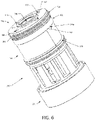
- the reservoir housing 200 includes a first closed mouthend 202 and an opposing second connecting end 204. Additionally, the reservoir housing 200 includes an outer wall 201 that extends from the mouthend 202 to the connecting end 204 along a direction parallel to the longitudinal axis Y of the aerosol delivery device 10.
- the reservoir housing 200 may include a mouthpiece portion 206 disposed proximate the mouthend 202 of the reservoir housing 200 and a storage portion 208 that extends from the mouthpiece portion 206 towards the connecting end 204 of the reservoir housing 200. Additionally, the storage portion 208 may extend from the mouthpiece portion 206 towards the connecting end 204 along a direction parallel to the longitudinal axis Y of the aerosol delivery device 10. According to some aspects, the storage portion 208 may be configured to receive various components of the aerosol delivery device 10 within the outer wall 201 of the reservoir housing 200, as discussed in greater detail below.
- the mouthpiece portion 206 disposed proximate the mouthend 202 of the reservoir housing 200 may include a tapered portion having a smaller diameter than other portions (e.g., storage portion 208) of the reservoir housing 200.
- the aerosol delivery device 10 may include a mouthpiece channel 216 that is formed of an outer wall 217 disposed within the reservoir housing 200.
- the mouthpiece channel 216 may be formed of an outer wall 217 that is substantially shaped as a cylindrical tube and is disposed interior to the outer wall 201 of the reservoir housing 200.
- the mouthpiece channel 216 may include an opening 214 disposed proximate to the mouthend 202 of the reservoir housing 200. The opening 214 may provide for egress of formed aerosol from the aerosol delivery device 10.
- the mouthpiece channel 216 may be configured to be in fluid communication with the opening 214. Additionally, the mouthpiece channel 216 may include a second opening 215 disposed proximate a terminal end 219 of the mouthpiece channel 216. The second opening 215 may also be in fluid communication with the mouthpiece channel 216 and may also provide for egress of formed aerosol from the aerosol delivery device 10.
- the mouthpiece channel 216 may be substantially tubular and cylindrical in shape. Additionally, the mouthpiece channel 216 may extend from the mouthend 202 to the terminal end 219 of the mouthpiece channel 216. In some aspects, the mouthpiece channel 216 may extend from the mouthend 202 and towards the connecting end 204 of the reservoir housing 200 along a direction parallel to the longitudinal axis Y of the aerosol delivery device 10. In some aspects, the mouthpiece channel 216 may taper as it extends from a first end to a second end of the mouthpiece channel 216. According to some aspects, the mouthpiece channel 216 may be shaped and/or arranged so as to mitigate the likelihood of a meniscus forming within the mouthpiece channel 216. For example, as shown in FIG.
- the mouthpiece channel 216 may be shaped to include a first portion 230, a second portion 232, and a transition therebetween that includes an elliptical orifice 234.
- the mouthpiece channel 216 may be shaped to include a first portion 230, a second portion 232, and a shoulder portion 236 disposed proximate therebetween that provides for a fluid trap configured to minimize the formation of condensation within the mouthpiece channel 216.
- the mouthpiece channel 216 may include fluted elements 238 extending radially inward from the outer wall 217 that forms the mouthpiece channel 216. According to some aspects, as shown in FIG.
- the fluted elements 238 may extend radially inward from the outer wall 217 so as to define a star-shaped radial cross-section of the mouthpiece channel 216 configured to prevent the formation of a meniscus therein. Additionally, the mouthpiece channel 216 may extend through a reservoir chamber 210 defined by the reservoir housing 200 and may be in fluid communication with the vaporizing assembly 300, as discussed in greater detail herein.
- the storage portion 208 may define, in part, a reservoir chamber 210 configured to store an aerosol precursor composition therein.
- the reservoir housing 200 may be substantially tubular in shape, and more particularly, the storage portion 208 may be substantially tubular and/or cylindrically shaped.
- the outer wall 201 that forms the substantially cylindrical tubular shaped reservoir housing 200 may include an interior surface 212.
- the outer wall 217 that forms the mouthpiece channel 216 may include an exterior surface 218.
- the interior surface 212 of the outer wall 201 that forms the reservoir housing 200 and the exterior surface 218 of the outer wall 217 that forms the mouthpiece channel 216 may define, in part, the reservoir chamber 210 configured to retain an amount of aerosol precursor composition therein.
- the reservoir housing 200 may further include at least one sealing member support 220.
- the reservoir housing 200 may include four sealing member support 220 arranged about the interior surface 212 of the outer wall 201 of the reservoir housing 200 in substantially equal angular intervals about the longitudinal axis Y of the aerosol delivery device 10.
- the reservoir housing 200 is shown as having four sealing member supports 220, one of ordinary skill in the art may appreciate that any number of sealing member supports are also encompassed by the present disclosure.
- the at least one sealing member support 220 may be integrally formed with the interior surface 212 of the outer wall 201.
- the sealing member support 220 may be securely affixed to the interior surface 212 of the reservoir housing 200.
- the sealing member supports 220 may extend from proximate the mouthend 202 of the reservoir housing to a terminal end 221 along a direction substantially parallel to the longitudinal axis Y of the aerosol delivery device 10. In some aspects, the sealing member supports 220 may extend longitudinally along the interior surface 212 of the outer wall 201 of the reservoir housing 200. Further, the sealing member supports 220 may extend along a direction substantially parallel to the mouthpiece channel 216.
- the mouthpiece channel 216 extends a greater distance along a direction substantially parallel to the longitudinal axis Y of the aerosol delivery device 10 than the distance any of the sealing member supports 220 extends along a direction substantially parallel to the longitudinal axis Y of the aerosol delivery device 10, as shown in FIG. 3 .
- the terminal end 219 of the mouthpiece channel 216 extends beyond the terminal end 221 of the sealing member support 220 from the mouthend 202 of the reservoir housing 200.
- the connecting end 204 of the reservoir housing 200 may be configured to receive a sealing member 500 therethrough.
- the sealing member 500 may be configured to directly engage the reservoir housing 200 so as to define the reservoir chamber 210 configured to retain the aerosol precursor composition therein. Additionally, the sealing member 500 may be in a sealing arrangement with the outer wall 201 of the reservoir housing 200 and the outer wall 217 of the mouthpiece channel 216 so as to define the reservoir chamber 210.
- the sealing member 500 may be configured to directly and sealingly engage the interior surface 212 of the storage portion 208 and the exterior surface 218 of the mouthpiece channel 216 such that the sealing member 500, the interior surface 212 of the storage portion 208, and the exterior surface 218 of the mouthpiece channel 216 define the reservoir chamber 210.
- the sealing member supports 220 may be configured to directly engage the sealing member 500 when the sealing member 500 is disposed and/or received within the reservoir housing 200.
- the sealing member 500 may be configured to directly engage the interior surface 212 of the storage portion 208 so as to substantially prevent the aerosol precursor composition from traversing a circumferential peripheral surface 502 of the sealing member 500 that directly and sealingly engages the interior surface 212 of the storage portion 208.
- the circumferential peripheral surface 502 of the sealing member 500 may further include at least one sealing element 504 that extends radially therefrom, as particularly shown in FIGS. 7A and 7B .
- the sealing element 504 may be configured to directly engage the interior surface 212 of the storage portion 208.
- the sealing element 504 may include a plurality of ridges, flanges, and/or the like that extend radially from and along the peripheral surface 502 of the sealing member 500 and are configured to directly and operably engage the interior surface 212 of the reservoir housing 200. When directly engaged with the interior surface 212, the sealing element 504 may be configured to substantially limit and/or prevent the aerosol precursor composition disposed within the reservoir chamber 210 from traversing the peripheral surface 502 of the sealing member 500 when the sealing member 500 is operably and directly engaged with the reservoir housing 200 and disposed therein.
- the mouthpiece channel 216 may be configured to directly engage the sealing member 500 when the sealing member 500 is disposed and/or received within the reservoir housing 200.
- the sealing member 500 may define a sealing member vapor orifice 506 that extends therethrough.
- the sealing member 500 may further include a flange portion 508 that may partially define a portion of the sealing member vapor orifice 506.
- the flange portion 508 may be shaped as an annular member that defines a medial portion of the sealing member vapor orifice 506.
- the flange portion 508 may define a distal or proximal portion of the sealing member vapor orifice 506.
- the portion of the sealing member vapor orifice 506 defined by the annular shaped flange portion 508 may have a smaller diameter than a diameter of at least another portion of the sealing member vapor orifice 506.
- the annular shaped flange portion 508 may be configured to directly and sealingly engage the mouthpiece channel 216.
- the flange portion 508 provides a seat for the mouthpiece channel 216 to substantially abut such that the sealing member 500, the interior surface 212 of the reservoir housing 200, and the exterior surface 218 of the mouthpiece channel 216 enclose a volume that defines the reservoir chamber 210.
- the sealing member vapor orifice 506 may be configured to provide for fluid communication between the mouthpiece channel 216 and the vaporizing assembly 300 when the mouthpiece channel 216 is disposed within the sealing member vapor orifice 506 and/or is substantially abutted against the flange portion 508 of the sealing member vapor orifice 506.
- the sealing member vapor orifice 506 may provide for fluid communication between the mouthpiece channel 216 and the vaporizing assembly 300 such that aerosol, vapor and/or the like formed by the vaporizing assembly 300 heating an aerosol precursor composition may egress the aerosol delivery device 10 via the opening 215 disposed proximate the terminal end 219 of the mouthpiece channel 216, the mouthpiece channel 216, and through the opening 214 disposed proximate the mouthend 202 of the reservoir housing 200.
- the operable engagement between the mouthpiece channel 216 and the sealing member vapor orifice 506 and/or the flange portion 508 may provide for an air-tight seal or a fluid-tight seal therebetween.
- the operable engagement between the mouthpiece channel 216 and the sealing member vapor orifice 506 and/or the flange portion 508 may advantageously prevent and/or substantially limit aerosol, vapor and/or the like formed by the vaporizing assembly 300 from entering the reservoir chamber 210.
- the operable engagement between the mouthpiece channel 216 and the sealing member vapor orifice 506 and/or the flange portion 508 may advantageously prevent and/or substantially limit the aerosol precursor composition retained within the reservoir chamber 210 from entering the mouthpiece channel 216, the sealing member vapor orifice 506, and/or the vaporizing assembly 300.
- the sealing member 500 may be further configured to directly engage at least one sealing member support 220 when the circumferential peripheral surface 502 of the sealing member 500 is directly engaged with an interior surface 212 of the reservoir housing 200 and/or when the sealing member vapor orifice 506 and/or the flange portion 508 of the sealing member 500 is directly engaged with the mouthpiece channel 216.
- a first planar surface 510 of the sealing member 500 may be oriented, exposed, faced and/or the like towards the reservoir chamber 210 when the sealing member 500 is operably engaged with the reservoir housing 200.
- the sealing member support 220 may substantially abut the first planar surface 510.
- the terminal end 221 of sealing member support 220 may substantially abut the first planar surface 510 of the sealing member 500 so as to prevent peripheral portions of the sealing member 500 from being displaced longitudinally towards the mouthend 202 of the reservoir housing 200. As shown in FIG.
- a longitudinal distance A exists between the flange portion 508 and the first planar surface 510 of the sealing member 500 such that the length of the distance A between the flange portion 508 and the first planar surface 510 of the sealing member 500 corresponds with the difference in length between the length of the mouthpiece channel 210 and the length of the sealing member support 220, as previously described herein.
- the sealing member 500 may further define a substrate engaging element 514 that extends along a direction parallel to the longitudinal axis Y of the aerosol delivery device 10.
- the substrate engaging element 514 may extend from a second planar surface 512, which is disposed opposite to the first planar surface 510 with respect to the longitudinal axis Y, of the sealing element 500.
- the sealing member 500 may be configured to operably engage the substrate member 400.
- the substrate engaging element 514 may be configured to directly engage the substrate member 400 so as to limit the substrate member 400 from being displaced radially from the longitudinal axis Y of the aerosol delivery device 10 with respect to the sealing member 500.
- the substrate engaging element 514 may be disposed within a substrate member vapor orifice 402 that is defined by the substrate member 400.
- the substrate member vapor orifice 402 of the substrate member 400 may extend through the substrate member 400 completely, and a diameter of the substrate member vapor orifice 402 may be substantially consistent along the entire length of the substrate member vapor orifice 402.
- the outermost diameter of the substrate engaging element 514 may be substantially equal to the diameter of the substrate member vapor orifice 402 such that when the substrate engaging element 514 is inserted therethrough, the substrate member 400 is prevented from being substantially displaced radially from the longitudinal axis Y with respect to the sealing member 500.
- Operable engagement between the substrate engaging element 514 of the sealing member 500 and the substrate member vapor orifice 402 may include a friction fit, press fit, interference fit, and/or the like such that radial displacement between the sealing member 500 and the substrate member 400 is substantially limited.
- the substrate member vapor orifice 402 may be configured to provide for fluid communication between any of the opening 214 of the mouthpiece channel 210 of the reservoir housing 200, the sealing member vapor orifice 506 of the sealing member 500, and the vaporizing assembly 300, such that aerosol, vapor and/or the like formed by the vaporizing assembly 300 heating an aerosol precursor composition may egress the aerosol delivery device 10 through the substrate member vapor orifice 402, the sealing member vapor orifice 506, the second opening 215 of the mouthpiece channel 216, the mouthpiece channel 216, and the opening 214 of the mouthpiece channel 216 disposed proximate the mouthend 202 of the reservoir housing 200.
- the sealing member 500 may further define at least one aerosol precursor composition orifice 516 that extends therethrough.
- the sealing member 500 may include four aerosol precursor composition orifices 516 that are arranged about the longitudinal axis Y of the aerosol delivery device 10 in substantially equal angular intervals.
- the at least one aerosol precursor composition orifice 516 is configured to provide for fluid communication between the reservoir chamber 210 and the substrate member 400.
- the substrate member 400 may include a first planar surface 404 that substantially abuts the second planar surface 512 of the sealing member 500 when the substrate engaging element 514 is directly engaged with the substrate member vapor orifice 402. Additionally, portions of the first planar surface 404 of the substrate member 400 may be exposed to respective aerosol precursor composition orifices 516 when the first planar surface 404 of the substrate member 400 substantially abuts the second planar surface 512 of the sealing member 500.
- the sealing member 500 may include any suitable number of aerosol precursor composition orifices 516 so as to provide for the precise transfer of a desired amount of aerosol precursor composition from the reservoir chamber 210 to the substrate member 400.
- Aerosol precursor composition orifices 516 may be shaped and/or configured so as to provide for the transfer of small volumes of liquid (i.e., an aerosol precursor composition and/or components thereof), such as milliliter or smaller, microliter or smaller, from the reservoir chamber 210 to the substrate member 400.
- an aerosol precursor composition orifice 516 may be shaped and/or configured so as to substantially limit and/or prevent any amount of aerosol precursor composition retained within the reservoir chamber 210 from vaporizing prematurely (i.e., vaporizing before being provided to the vaporizing assembly 300).
- the aerosol precursor composition orifice 516 may be shaped and/or configured such that a pressure within the reservoir chamber 210 does not decrease past an operational threshold during use of the aerosol delivery device 10.
- the aerosol precursor composition orifice 516 may be approximately 0.047 mm. According to another aspect, the aerosol precursor composition orifice 516 may be about 0.065 mm.
- the aerosol precursor composition orifice 516 may be about 0.080 mm. Additionally, the aerosol precursor composition orifice 516 may be sized in response to the surface energy of the aerosol precursor composition retained within the reservoir chamber 210. Such sizing can particularly be adapted to substantially resist bulk liquid flow from the reservoir chamber 210 until a negative pressure is applied (i.e., via a draw on the mouthend of the mouthend 202 of the device), at which time the desired volume of liquid may be expressed through the aerosol precursor composition orifice 516.
- the aerosol precursor composition orifice(s) can have a size in the range of about 0.02 mm to about 0.11 mm, about 0.03 mm to about 0.1 mm, or about 0.04 mm to about 0.09 mm.
- each orifice may have substantially the same size, or two or more orifices may have different sizes.
- another consideration when sizing the aerosol precursor composition orifice(s) 516 may include the density of the substrate, the amount of negative pressure within the aerosol delivery device during user operation, and/or the material selection of the sealing member 500.
- the sealing member 500 may provide for the transfer of an aerosol precursor composition from the reservoir chamber 210 to the substrate member 400 in small, precise volumes and may provide for improving aerosol formation and/or reducing unnecessary power drain.
- FIGS. 3 and 5 illustrate the reservoir housing 200 defines a single reservoir chamber 210 when the sealing member 500 is disposed within and operably engaged with the reservoir housing 200
- an aerosol delivery device 10 may include a reservoir housing 200 defining any number of reservoir chambers 210.
- a sealing member 500 defining four aerosol precursor composition orifices 516 may be operably engaged with a reservoir housing 200 that defines four distinct reservoir chambers 210 that are each compartmentalized and separated from one another.
- each of the distinct reservoir chambers would be configured to fluidly communicate with a designated aerosol precursor composition orifice and would not be in fluid communication with any other reservoir chamber.
- components of an aerosol precursor composition may be separated and compartmentalized in distinct reservoir chambers and may be provided to the substrate member 400 in specific quantities based at least in part on the shape, configuration, and/or size of the specific aerosol precursor composition orifice 516 that is in fluid communication with the respective reservoir chamber.
- the substrate member 400 is illustrated as being substantially annular in shape in FIGS. 7A and 7B , other suitable shapes (e.g., a rectangular ring, triangular ring or the like) and dimensions are also encompassed by the present disclosure.
- the substrate member 400 can have a relatively small thickness (e.g., about 1mm to about 20 mm, about 1.5 to about 15 mm, or about 2 mm to about 10 mm).
- FIGS. 7A and 7B illustrate that the first planar surface 404 of the substrate member 400 defines a surface area that is substantially equal to a surface area of an opposing second planar surface 406 of the substrate member 400.
- the substrate member 400 defines a surface area of the first and second planar surfaces 404, 406, which are both about 0.5 cm2 to about 50 cm2, about 1 cm2 to about 45 cm2, about 2 cm2 to about 40 cm2, or about 3 cm2 to about 30 cm2.
- the substrate member 400 can be formed of any material that is sufficiently and/or substantially inert with respect to the aerosol precursor composition and with respect to the amount of heating required for the vaporization of the aerosol precursor composition.
- the substrate member 400 is preferably chemically non-reactive with the components of the aerosol precursor composition (including aerosol forming materials, flavoring materials, and the like).
- the substrate member 400 is preferably thermally and mechanically stable under the conditions of use.
- the substrate member 400 may be formed of a material that is temperatures stable at a temperature of about 100 °C or greater, about 150 °C or greater, about 200 °C or greater, about 300 °C or greater, about 400 °C or greater, or about 500 °C or greater.
- the substrate member 400 may include a plurality of layers of nonwoven fibers.
- the substrate member 400 may include cellulose acetate (CA) fibers, polyethylene terephthalate (PET) bicomponent fibers, polyvinyl alcohol (PVOH) fibers, and/or the like.
- CA cellulose acetate
- PET polyethylene terephthalate
- PVOH polyvinyl alcohol
- Other materials, such as fiberglass fibers, are also encompassed by the present disclosure.
- the substrate member 400 may include fiberglass fibers, a porous ceramic material, particularly a silicon-based material, a silicon nitride material, and/or a porous glass or quartz material.
- certain thermoplastic materials such as cyclic olefin copolymers (COC) can be incorporated within the substrate member 400.
- the substrate member 400 may include wicking and/or porous materials that provide for the movement of the aerosol precursor composition therethrough (e.g., via capillary action), such that the aerosol precursor composition may be drawn to a liquid transport element 314, as described in greater detail herein.
- the substrate member 400 may include any combination of materials to provide for capillary action so as to provide the liquid transport element 314 an amount of aerosol precursor composition, as described in U.S. Pat. App. Ser. No. 14/989,109, filed January 5, 2016 , which is incorporated by reference herein in its entirety.
- the vaporizing assembly 300 configured to be at least partially received within the reservoir housing 200 may include an atomizer housing 306 and a connector housing 330 operably engaged therewith.
- the atomizer housing 306 may be disposed proximate a vaporizing end 302 of the vaporizing assembly 300, and the connector housing 300 may be disposed proximate an opposed connecting end 304 of the vaporizing assembly 300.
- the atomizer housing 306 may be operably engaged with the connector housing 330 in a friction fit, interference fit, magnetic fit, snap fit and/or the like.
- the atomizer housing 306 and the connector housing 330 may be securely affixed and/or attached to one another through ultrasonic welding and/or the like. Although the atomizer housing 306 and the connector housing 330 are illustrated as being separate members, the atomizer housing 306 and the connector housing 330 may be integrally formed with one another.
- the atomizer housing 306 and/or the connector housing 330 may be sized and/or shaped such that the atomizer housing 306 and/or at least a portion of the connector housing 330 are disposed within the reservoir housing 200, as shown in FIG. 1 .
- the atomizer housing 306 may include a plurality of sealing elements 308 configured to directly engage an interior surface 212 of the reservoir housing 200.
- the sealing element 308 may include a plurality of ridges, flanges, and/or the like that extend circumferentially about a peripheral surface of the atomizer housing 306.
- the sealing elements 308 may be configured to substantially limit and/or prevent the aerosol precursor composition and/or any aerosol formed within a vaporizing chamber 310 from traversing the sealing elements 308 disposed on the peripheral surface of the atomizer housing 306 and escape the aerosol delivery device 10 via means other than the mouthpiece channel 216 and/or the openings 214, 215 of the mouthpiece channel 216.
- the aerosol delivery device 10 includes an atomizer 312 disposed within the vaporizing chamber 310.
- the atomizer 312 includes an liquid transport element 314 that includes a first end 314a and a second end 314b.
- first and second ends 314a, 314b of the liquid transport element 314 may substantially abut a portion of the second planar surface 406 of the substrate member 400 such that the liquid transport element 314 is in fluid communication with the substrate member 400.
- a medial portion of the liquid transport element 314 extends between the first end 314a and the second end 314b and may include wicking and/or porous materials that provide for the movement of the aerosol precursor composition therethrough (e.g., via capillary action), such that the aerosol precursor composition may be drawn proximate to a heating element 316.
- the substrate member 400 may define at least one orifice configured to receive at least a portion of the liquid transport element 314 proximate the first and second ends 314a, 314b therethrough.
- the substrate member 400 may define an orifice sized similarly to an aerosol precursor composition orifice 516 defined by the sealing member 500, and the orifice defined by the substrate member 400 may be aligned with the aerosol precursor composition orifice 516 of the sealing member 500.
- a portion of the liquid transport element 314 proximate the first and second ends 314a, 314b may extend though the orifice defined by the substrate member 400 and the aligned aerosol precursor composition orifice 516 of the sealing member 500 so as to be in direct fluid communication with the aerosol precursor composition within the reservoir chamber 210.
- the first and second ends 314a, 314b extending through the aerosol precursor composition orifices 516 may provide for the movement of the aerosol precursor composition within the reservoir chamber 210 (e.g., via capillary action), such that the aerosol precursor composition is drawn proximate to the heating element 316.
- the remaining aerosol precursor composition orifices 516 not engaged with the first and second ends 314a, 314b of the liquid transport element 314 may be engaged with the substrate member 400 so as to retain the aerosol precursor composition within the reservoir chamber 210 and/or to provide for the precise transfer of a desired amount of aerosol precursor composition from the reservoir chamber 210 to the substrate member 400.
- the heating element 316 may be in a heating arrangement with the liquid transport element 314.
- the heating element 316 may extend at least partially about the medial portion of the liquid transport element 314, and more particularly, may extend at least partially about the liquid transport element 314 at a position between the first end 314a and the second end 314b of the liquid transport element 314.
- the heating element 316 may be configured to heat the aerosol precursor composition disposed within the medial portion of the liquid transport element 314 to produce an aerosol for inhalation by a user.
- the heating element 316 may be formed from a material that provides resistive heating when an electrical current is applied thereto.
- the resistive heating element 316 may include a wire defining a plurality of coils wound about the medial portion of the liquid transport element 314. Additionally, as shown in FIGS. 8-11 , the heating element 316 may include a wire material that provides resistive heating and may extend between a first electrical terminal 318a and a second electrical terminal 318b.
- the wire material may include Kanthal (FeCrAl), Nichrome, Molybdenum disilicide (MoSi2), Molybdenum disilicide doped with Aluminum (Mo(Si,Al)2), ceramics (e.g., a positive temperature coefficient ceramic), titanium and/or related alloys in some aspects, although various other materials may be employed in other aspects.
- the heating element 316 may be formed by winding the wire about the liquid transport element 314 as described in U.S. Pat. No. 9,210,738 to Ward et al. , which is incorporated herein by reference in its entirety.
- the heating element 316 may be configured to heat the aerosol precursor composition disposed within the liquid transport element 314 via radiant heating, as described in U.S. Pat. App. Ser. Nos. 14/808,405, filed July 24, 2015 ; 14/958,651, filed December 3, 2015 , the contents of which are incorporated herein in their entirety by reference.
- the heating element 316 may be configured to heat the aerosol precursor composition via inductive heating, as described in U.S. Pat. App. Ser. Nos. 14/958,651, filed December 3, 2015 ; 14/934,763, filed November 6, 2015 , the contents of which are incorporated herein in their entirety by reference.
- the first electrical terminal 318a and a second electrical terminal 318b may be configured to provide the resistive heating element 316 with an electrical current when the vaporizing assembly 300 is operably engaged with a power source assembly 600.
- the heating element 316 may be integrally formed with the first and second electrical terminals 318a, 318b.
- the heating element 316 may be operably engaged with and in electrical communication with the first and second electrical terminals 318a, 318b. For example, portions of the heating element 316 may be welded, soldered, brazed, and/or the like to the respective first and second electrical terminals 318a, 318b.
- the first and second electrical terminals 318a, 318b may operably engage the power source disposed within the power source assembly 600 with the first and second electrical terminal tabs 319a, 319b.
- a circuit may be completed when the first and second electrical tabs 319a, 319b are operably engaged with the power source disposed in the power source assembly 600.
- the power source may provide an electrical current through the heating element 316 when the first and second electrical tabs 319a, 319b complete the electrical circuit and are engaged with the first and second electrical terminals 318a, 318b.
- the aerosol precursor composition disposed within the medial portion of the liquid transport element 314 is heated by the wire coils of the heating element 316 wound about the medial portion of the transport element 314.
- heating element 316 is illustrated as a wire having a plurality of coils wound about the aerosol precursor transport element 314, additional forms for the heating element 316 are also encompassed by this disclosure, such as a heating element in the form of a foil, a foam, discs, spirals, fibers, wires, films, yarns, strips, ribbons, and/or cylinders.
- first and second electrical terminals 318a, 318b may be configured to provide an electrical current to the heating element 316 when a control component of the aerosol delivery device 10, which may be disposed within the vaporizing assembly 300, the reservoir housing 200, and/or the power source assembly 600, actuates electrical current flow from the power source to the heating element 316 via the first and second electrical terminals 318a, 318b.
- the aerosol delivery device 10 may include a control component (i.e., a controller) 322 configured to at least control the heating of the heating element 316 and/or other operations of the aerosol delivery device 10 (e.g., powering and/or actuating various visual indicia and/or the like).
- the vaporizing assembly 300 may include a control component 322 and at least one control component terminal 320.
- the aerosol delivery device 10 may include a control component 322 as described in U.S. Pat. App. Pub. No. 2015/0245658 to Worm et al. , which is incorporated herein by reference in its entirety.
- the control component terminal 320 may be configured to operably engage the power source (not shown) disposed in the power source assembly 600 when the connector housing 330 is directly and/or mechanically engaged with the power source assembly 600.
- the control component terminal 320 may be operably engaged with the power source so as to provide an electrical current to power the control component 322 to control the various operations of the aerosol delivery device 10.
- control component terminal 320 may be configured to receive electrical signals from additional and/or alternative control components (e.g., a separate control component, etc.) disposed within the power source assembly 600. Additionally, the control component terminal 320 may be configured to provide for electrical communication (i.e., electrical current, data signals, and/or the like) between a control component disposed within the power source assembly 600 and the control component 322 disposed within the vaporizing assembly 300. Additionally or alternatively, the power source assembly 600 may include a single control component (not shown) therein that is configured to control various operations of the aerosol delivery device 10, as previously described herein.
- the power source assembly 600 may include a housing configured to store a control component and/or a control component terminal therein, as described in U.S. Pat. App. Pub. No. 2015/0335071 to Brinkley et. al , which is incorporated herein by reference in its entirety.
- the connector housing 330 of the vaporizing assembly 300 may be configured to operably and/or mechanically engage the power source assembly 600.
- the connector housing 330 may be configured to receive at least a portion of the power source assembly 600 therein.
- the connector housing 330 may be configured to provide access to at least one of the first electrical terminal 318a, the second electrical terminal 318b, and/or the control component terminal 320.
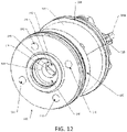
- the connector housing 330 may include a coupler 332 configured to directly and mechanically engage at least a portion of the power source assembly 600.
- the coupler 332 may define a plurality of apertures 340a, 340b, 340c configured to receive the first electrical terminal 318a, the second electrical terminal 318b, and the control component terminal 320 therethrough respectively. Further, the coupler 332 may be particularly shaped and/or configured such that the connector housing 330 may only mechanically engage an authentic power source assembly 600. In particular, an authentic power source assembly 600 may be reciprocally shaped with respect to the coupler 332 such that the appropriate engagement between the power source assembly 600 and the connector housing 330 may only be accomplished when authentic power source assemblies 600 are engaged with authentic connector housings 330.
- an authentic connector housing 330 may include a coupler 332 disposed proximate the connecting end 304 of the vaporizing assembly 300.
- the coupler 332 may provide benefits in terms of ease of assembly and easy of attachment to the power source assembly 600.
- the coupler 332 may be particularly shaped such that the reciprocally shaped power source assembly 600 may only mechanically engage the coupler 332 when the components are particularly aligned with respect to one another (i.e., axially and rotationally aligned with one another).
- the coupler 332 may include an anti-rotation mechanism 334 configured to prevent rotation of the vaporizing assembly 300 with respect to the power source assembly 600 when engaged therewith.
- the anti-rotation mechanism 334 may be configured to prevent rotation of the reservoir housing 200 with respect to the power source assembly 600 when the connector housing 330 is mechanically engaged with the power source assembly 600.
- Such anti-rotation mechanisms are described in greater detail in U.S. Pat. App. Pub. No. 2014/0261495 to Novak III, et al. , which is incorporated herein in its entirety by reference.
- the anti-rotation mechanism 334 may include a plurality of protrusions 336a, 336b, 336c, 336d, 336e, 336f and a plurality of recesses 338a, 338b, 338c, 338d, 338e, 338f disposed about an outer periphery of a coupler 332 in an alternating arrangement.
- the power source assembly 600 may include a reciprocal arrangement (not shown) of a plurality of recesses and a plurality of protrusions configured to directly engage the plurality of protrusions 336a, 336b, 336c, 336d, 336e, 336f and the plurality of recesses 338a, 338b, 338c, 338d, 338e, 338f alternatingly disposed about the outer periphery of the coupler 332.
- the anti-rotation mechanism 334 of the connector housing 330 may advantageously provide for ease of alignment and reliable engagement with the power source assembly 600 when operably and directly engaged therewith.
- the anti-rotation mechanism 334 may provide for alignment of the connector housing 330 with the power source assembly 600 such that the first and second heating terminals 318a, 318b and/or the control component terminal 320 are aligned with respective terminals, connectors, and/or the like disposed within the power source assembly 600 when the connector housing 330 is engaged therewith. Further, the anti-rotation mechanism 334 may substantially limit any rotation of the connector housing 330 with respect to the power source assembly 600 when the connector housing 330 and the power source assembly 600 are mechanically engaged therewith.
- the connector housing 330 may include additional engagement assemblies that provide for a threaded fit, friction fit, interference fit, magnetic fit, and/or the like with the power source assembly 600.
- aspects of the present disclosure may provide for a method 1300 of manufacturing a liquid storage tank for an aerosol delivery device.
- the method 1300 may include providing a reservoir chamber 1302 defined, in part, by an outer housing formed of a wall and a central tube interior to the outer housing and formed of a wall.
- the reservoir chamber 210 may be defined, in part, by the interior surface 212 of the outer wall 201 that forms the reservoir housing 200 and the exterior surface 218 of the outer wall 217 that forms the mouthpiece channel 216.
- the outer housing (e.g., the reservoir housing 200) may include a closed mouthend and an opposing connecting end, and the central tube (e.g., the mouthpiece channel 216) may have a first end opening through the closed mouthend of the outer housing and a second opposing open end.
- the method 1300 may further include dispensing an amount of aerosol precursor composition within the reservoir chamber 1304.
- the method may include dispensing the aerosol precursor composition into the reservoir chamber from the connecting end of the outer housing and in between the exterior surface of the outer wall of the central tube and the interior surface of the outer wall of the outer housing.
- the method 1300 may further include inserting a sealing member into the outer housing 1306.
- the method may include inserting a sealing member, such as the sealing member 500 illustrated in FIGS. 7A and 7B , into the outer housing from the connecting end of the outer housing.
- the sealing member may include a central orifice (e.g., a sealing member vapor orifice 506) configured to provide for fluid communication between any of the openings of the central tube (e.g., the opening 215 disposed at the terminal end 219 of the mouthpiece channel 216 and/or the opening 214 of the mouthpiece channel 216 disposed proximate the mouthend 202 of the reservoir housing 200), the central tube (e.g., the mouthpiece channel 216), and/or a vaporizing chamber (e.g., the vaporizing chamber 310).
- a central orifice e.g., a sealing member vapor orifice 506
- the method may include inserting the sealing member into the outer housing so as to engage a peripheral portion of the sealing member with the wall of the outer housing and the central orifice of the sealing member with the second open end of the central tube in a sealing arrangement.
- the sealing member may include a sealing element that surrounds the circumferential periphery of the sealing member.
- the central orifice of the sealing member may include an annular flange portion that provides a seat for the central tube, which the central tube may substantially abut when the central tube is in a sealing arrangement with the sealing member, as described previously herein.
- the method 1300 may further include inserting a substrate member adjacent to the sealing member 1308.
- the substrate member may be inserted into the outer housing from the connecting end of the outer housing and may be disposed within the outer housing and substantially abut the sealing member when inserted within the outer housing.
- the method may include inserting the substrate member adjacent to the sealing member such that a substrate engaging member is inserted within a central orifice of the substrate member, as previously described herein.
Applications Claiming Priority (3)
| Application Number | Priority Date | Filing Date | Title |
|---|---|---|---|
| US15/202,947 US10085485B2 (en) | 2016-07-06 | 2016-07-06 | Aerosol delivery device with a reservoir housing and a vaporizer assembly |
| PCT/IB2017/054059 WO2018007965A1 (fr) | 2016-07-06 | 2017-07-05 | Dispositif de distribution d'aérosol pourvu d'un corps de réservoir et d'un ensemble vaporisateur |
| EP17748934.1A EP3481242B1 (fr) | 2016-07-06 | 2017-07-05 | Dispositif de distribution d'aérosol pourvu d'un corps de réservoir et d'un ensemble vaporisateur |
Related Parent Applications (2)
| Application Number | Title | Priority Date | Filing Date |
|---|---|---|---|
| EP17748934.1A Division EP3481242B1 (fr) | 2016-07-06 | 2017-07-05 | Dispositif de distribution d'aérosol pourvu d'un corps de réservoir et d'un ensemble vaporisateur |
| EP17748934.1A Division-Into EP3481242B1 (fr) | 2016-07-06 | 2017-07-05 | Dispositif de distribution d'aérosol pourvu d'un corps de réservoir et d'un ensemble vaporisateur |
Publications (1)
| Publication Number | Publication Date |
|---|---|
| EP4011225A1 true EP4011225A1 (fr) | 2022-06-15 |
Family
ID=59523203
Family Applications (2)
| Application Number | Title | Priority Date | Filing Date |
|---|---|---|---|
| EP17748934.1A Active EP3481242B1 (fr) | 2016-07-06 | 2017-07-05 | Dispositif de distribution d'aérosol pourvu d'un corps de réservoir et d'un ensemble vaporisateur |
| EP22155340.7A Pending EP4011225A1 (fr) | 2016-07-06 | 2017-07-05 | Dispositif d'administration d'aérosol doté d'un boîtier de réservoir et d'un ensemble vaporisateur |
Family Applications Before (1)
| Application Number | Title | Priority Date | Filing Date |
|---|---|---|---|
| EP17748934.1A Active EP3481242B1 (fr) | 2016-07-06 | 2017-07-05 | Dispositif de distribution d'aérosol pourvu d'un corps de réservoir et d'un ensemble vaporisateur |
Country Status (10)
| Country | Link |
|---|---|
| US (5) | US10085485B2 (fr) |
| EP (2) | EP3481242B1 (fr) |
| JP (1) | JP7019664B2 (fr) |
| KR (2) | KR20230034426A (fr) |
| CN (2) | CN114271543A (fr) |
| CA (1) | CA3029529A1 (fr) |
| ES (1) | ES2950994T3 (fr) |
| PL (1) | PL3481242T3 (fr) |
| RU (1) | RU2733366C2 (fr) |
| WO (1) | WO2018007965A1 (fr) |
Families Citing this family (37)
| Publication number | Priority date | Publication date | Assignee | Title |
|---|---|---|---|---|
| GB201407056D0 (en) * | 2014-04-22 | 2014-06-04 | Essentra Filter Products Dev Co Pte Ltd | Smoking article |
| CN205197001U (zh) * | 2015-11-25 | 2016-05-04 | 深圳市合元科技有限公司 | 分体式雾化器、电子烟及便于更换的储液装置 |
| US10881140B2 (en) | 2016-06-20 | 2021-01-05 | Altria Client Services Llc | Vaporiser assembly for an aerosol-generating system |
| US10085485B2 (en) | 2016-07-06 | 2018-10-02 | Rai Strategic Holdings, Inc. | Aerosol delivery device with a reservoir housing and a vaporizer assembly |
| US10051894B2 (en) | 2016-08-01 | 2018-08-21 | Altria Client Services Llc | Cartridge and e-vaping device with serpentine heater |
| US10143239B2 (en) | 2016-08-01 | 2018-12-04 | Altria Client Services Llc | Cartridge and e-vaping device |
| EA039375B1 (ru) | 2016-12-27 | 2022-01-20 | Джуул Лэбз, Инк. | Термический фитиль для электронных вапорайзеров |
| JP6959429B2 (ja) * | 2017-09-06 | 2021-11-02 | ケーティー・アンド・ジー・コーポレーション | エアロゾル生成装置 |
| US10660370B2 (en) * | 2017-10-12 | 2020-05-26 | Rai Strategic Holdings, Inc. | Aerosol delivery device including a control body, an atomizer body, and a cartridge and related methods |
| US10561176B2 (en) * | 2017-10-19 | 2020-02-18 | Fuma International, Llc | Vaping atomizer |
| USD861594S1 (en) * | 2017-11-24 | 2019-10-01 | Shenzhen Smoore Technology Limited | Electronic cigarette power supply device |
| USD861549S1 (en) * | 2018-01-18 | 2019-10-01 | Shenzhen Smoore Technology Limited | Electronic cigarette power supply device |
| USD874721S1 (en) * | 2018-01-18 | 2020-02-04 | Shenzhen Smoore Technology Limited | Electronic cigarette power supply device |
| CN108185536B (zh) | 2018-02-13 | 2020-01-21 | 深圳麦克韦尔科技有限公司 | 电子烟及其雾化器 |
| WO2019157651A1 (fr) | 2018-02-13 | 2019-08-22 | 深圳麦克韦尔股份有限公司 | Cigarette électronique, ensemble chauffant et élément chauffant associé |
| USD870034S1 (en) * | 2018-06-13 | 2019-12-17 | Shenzhen Smoore Technology Limited | Power supply device for electronic cigarette |
| ES2929474T3 (es) | 2018-07-23 | 2022-11-29 | Juul Labs Inc | Gestión del flujo de aire para dispositivo vaporizador |
| JP2021532782A (ja) | 2018-07-31 | 2021-12-02 | ジュール・ラブズ・インコーポレイテッドJuul Labs, Inc. | カートリッジベースの非燃焼加熱式気化器 |
| FR3087093A1 (fr) | 2018-10-15 | 2020-04-17 | Juul Labs, Inc. | Element chauffant |
| WO2020097085A1 (fr) | 2018-11-05 | 2020-05-14 | Juul Labs, Inc. | Cartouches pour dispositifs vaporisateurs |
| US11156766B2 (en) | 2018-11-19 | 2021-10-26 | Rai Strategic Holdings, Inc. | Aerosol delivery device |
| CN213215328U (zh) * | 2019-01-21 | 2021-05-18 | 浙江迈博高分子材料有限公司 | 一种储液元件、导液元件、冷却元件及支撑元件 |
| US11253001B2 (en) | 2019-02-28 | 2022-02-22 | Juul Labs, Inc. | Vaporizer device with vaporizer cartridge |
| US20220142253A1 (en) * | 2019-03-11 | 2022-05-12 | Nicoventures Trading Limited | Aerosol provision device |
| WO2020205561A1 (fr) * | 2019-03-29 | 2020-10-08 | Juul Labs, Inc. | Cartouches pour dispositifs de vaporisation |
| JP2022525904A (ja) * | 2019-04-03 | 2022-05-20 | フィリップ・モーリス・プロダクツ・ソシエテ・アノニム | マルチチャネルで、かつ気流が反転された、エアロゾル発生物品用マウスピース |
| CN210203316U (zh) * | 2019-05-07 | 2020-03-31 | 深圳市合元科技有限公司 | 烟弹及电子烟 |
| US20210016019A1 (en) * | 2019-07-19 | 2021-01-21 | Convexity Scientific Inc. | Flow-stop enabled mouthpiece, and portable nebulizer thereof |
| US20210052833A1 (en) * | 2019-08-22 | 2021-02-25 | Convexity Scientific Inc. | Mouthpiece of a nebulizer, and portable nebulizer thereof |
| GB201914831D0 (en) * | 2019-10-14 | 2019-11-27 | Nicoventures Trading Ltd | Aerosol provision systems |
| CN214594151U (zh) * | 2020-08-27 | 2021-11-05 | 常州市派腾电子技术服务有限公司 | 雾化器及气溶胶发生装置 |
| US11707088B2 (en) | 2020-09-25 | 2023-07-25 | Rai Strategic Holdings, Inc. | Aroma delivery system for aerosol delivery device |
| US11856986B2 (en) | 2020-10-19 | 2024-01-02 | Rai Strategic Holdings, Inc. | Customizable panel for aerosol delivery device |
| KR102550143B1 (ko) * | 2021-06-24 | 2023-06-30 | 주식회사 케이티앤지 | 증기화기 및 이를 포함하는 에어로졸 생성 장치 |
| US20230107943A1 (en) | 2021-10-01 | 2023-04-06 | Rai Strategic Holdings, Inc. | Mouthpiece for aerosol delivery device |
| US20230105080A1 (en) | 2021-10-01 | 2023-04-06 | Rai Strategic Holdings, Inc. | Absorbent containing mouthpiece for aerosol delivery device |
| US20240057691A1 (en) | 2022-08-19 | 2024-02-22 | Rai Strategic Holdings, Inc. | Pressurized aerosol delivery device |
Citations (17)
| Publication number | Priority date | Publication date | Assignee | Title |
|---|---|---|---|---|
| US5934289A (en) | 1996-10-22 | 1999-08-10 | Philip Morris Incorporated | Electronic smoking system |
| US5954979A (en) | 1997-10-16 | 1999-09-21 | Philip Morris Incorporated | Heater fixture of an electrical smoking system |
| US5967148A (en) | 1997-10-16 | 1999-10-19 | Philip Morris Incorporated | Lighter actuation system |
| US6040560A (en) | 1996-10-22 | 2000-03-21 | Philip Morris Incorporated | Power controller and method of operating an electrical smoking system |
| US20100028766A1 (en) | 2008-07-18 | 2010-02-04 | University Of Maryland | Thin flexible rechargeable electrochemical energy cell and method of fabrication |
| US7726320B2 (en) | 2006-10-18 | 2010-06-01 | R. J. Reynolds Tobacco Company | Tobacco-containing smoking article |
| EP2399636A1 (fr) * | 2010-06-23 | 2011-12-28 | Philip Morris Products S.A. | Générateur d'aérosol amélioré et partie de stockage de liquide pour une utilisation avec le générateur d'aérosol |
| US20130319438A1 (en) * | 2012-06-05 | 2013-12-05 | Qiuming Liu | Electronic Cigarette and Its Sucking Rod |
| US20140096781A1 (en) | 2012-10-08 | 2014-04-10 | R. J. Reynolds Tobacco Company | Electronic smoking article and associated method |
| US20140261495A1 (en) | 2013-03-15 | 2014-09-18 | R.J. Reynolds Tobacco Company | Cartridge and control body of an aerosol delivery device including anti-rotation mechanism and related method |
| US8881737B2 (en) | 2012-09-04 | 2014-11-11 | R.J. Reynolds Tobacco Company | Electronic smoking article comprising one or more microheaters |
| EP2801271A2 (fr) * | 2013-05-07 | 2014-11-12 | Shenzhen First Union Technology Co., Ltd. | Dispositif d'atomisation et cigarette électronique comportant celui-ci |
| US20150216232A1 (en) | 2014-02-03 | 2015-08-06 | R.J. Reynolds Tobacco Company | Aerosol Delivery Device Comprising Multiple Outer Bodies and Related Assembly Method |
| US20150245658A1 (en) | 2014-02-28 | 2015-09-03 | R.J. Reynolds Tobacco Company | Control body for an electronic smoking article |
| US20150335071A1 (en) | 2014-05-23 | 2015-11-26 | R.J. Reynolds Tobacco Company | Sealed Cartridge for an Aerosol Delivery Device and Related Assembly Method |
| US9210738B2 (en) | 2012-12-07 | 2015-12-08 | R.J. Reynolds Tobacco Company | Apparatus and method for winding a substantially continuous heating element about a substantially continuous wick |
| EP3015010A1 (fr) * | 2014-10-29 | 2016-05-04 | Shenzhen Smoore Technology Limited | Atomiseur, ensemble d'atomisation et inhalateur |
Family Cites Families (187)
| Publication number | Priority date | Publication date | Assignee | Title |
|---|---|---|---|---|
| US2057353A (en) | 1936-10-13 | Vaporizing unit fob therapeutic | ||
| US1771366A (en) | 1926-10-30 | 1930-07-22 | R W Cramer & Company Inc | Medicating apparatus |
| US2104266A (en) | 1935-09-23 | 1938-01-04 | William J Mccormick | Means for the production and inhalation of tobacco fumes |
| US3200819A (en) | 1963-04-17 | 1965-08-17 | Herbert A Gilbert | Smokeless non-tobacco cigarette |
| US4284089A (en) | 1978-10-02 | 1981-08-18 | Ray Jon P | Simulated smoking device |
| US4303083A (en) | 1980-10-10 | 1981-12-01 | Burruss Jr Robert P | Device for evaporation and inhalation of volatile compounds and medications |
| SE8405479D0 (sv) | 1984-11-01 | 1984-11-01 | Nilsson Sven Erik | Sett att administrera flyktiga, fysiologiskt, aktiva emnen och anordning for detta |
| US4735217A (en) | 1986-08-21 | 1988-04-05 | The Procter & Gamble Company | Dosing device to provide vaporized medicament to the lungs as a fine aerosol |
| GB8713645D0 (en) | 1987-06-11 | 1987-07-15 | Imp Tobacco Ltd | Smoking device |
| US5019122A (en) | 1987-08-21 | 1991-05-28 | R. J. Reynolds Tobacco Company | Smoking article with an enclosed heat conductive capsule containing an aerosol forming substance |
| US4922901A (en) | 1988-09-08 | 1990-05-08 | R. J. Reynolds Tobacco Company | Drug delivery articles utilizing electrical energy |
| US4947875A (en) | 1988-09-08 | 1990-08-14 | R. J. Reynolds Tobacco Company | Flavor delivery articles utilizing electrical energy |
| US4947874A (en) | 1988-09-08 | 1990-08-14 | R. J. Reynolds Tobacco Company | Smoking articles utilizing electrical energy |
| US4986286A (en) | 1989-05-02 | 1991-01-22 | R. J. Reynolds Tobacco Company | Tobacco treatment process |
| US4945931A (en) | 1989-07-14 | 1990-08-07 | Brown & Williamson Tobacco Corporation | Simulated smoking device |
| US5144962A (en) | 1989-12-01 | 1992-09-08 | Philip Morris Incorporated | Flavor-delivery article |
| US5093894A (en) | 1989-12-01 | 1992-03-03 | Philip Morris Incorporated | Electrically-powered linear heating element |
| US5408574A (en) | 1989-12-01 | 1995-04-18 | Philip Morris Incorporated | Flat ceramic heater having discrete heating zones |
| US5060671A (en) | 1989-12-01 | 1991-10-29 | Philip Morris Incorporated | Flavor generating article |
| US5042510A (en) | 1990-01-08 | 1991-08-27 | Curtiss Philip F | Simulated cigarette |
| US5249586A (en) | 1991-03-11 | 1993-10-05 | Philip Morris Incorporated | Electrical smoking |
| US5530225A (en) | 1991-03-11 | 1996-06-25 | Philip Morris Incorporated | Interdigitated cylindrical heater for use in an electrical smoking article |
| US5505214A (en) | 1991-03-11 | 1996-04-09 | Philip Morris Incorporated | Electrical smoking article and method for making same |
| US5726421A (en) | 1991-03-11 | 1998-03-10 | Philip Morris Incorporated | Protective and cigarette ejection system for an electrical smoking system |
| US5261424A (en) | 1991-05-31 | 1993-11-16 | Philip Morris Incorporated | Control device for flavor-generating article |
| IL104930A (en) | 1992-03-25 | 1995-12-31 | Reynolds Tobacco Co R | Components for smoking articles and their manufacture |
| US5353813A (en) | 1992-08-19 | 1994-10-11 | Philip Morris Incorporated | Reinforced carbon heater with discrete heating zones |
| US5322075A (en) | 1992-09-10 | 1994-06-21 | Philip Morris Incorporated | Heater for an electric flavor-generating article |
| US5498850A (en) | 1992-09-11 | 1996-03-12 | Philip Morris Incorporated | Semiconductor electrical heater and method for making same |
| US5369723A (en) | 1992-09-11 | 1994-11-29 | Philip Morris Incorporated | Tobacco flavor unit for electrical smoking article comprising fibrous mat |
| US5441060A (en) | 1993-02-08 | 1995-08-15 | Duke University | Dry powder delivery system |
| US5372148A (en) | 1993-02-24 | 1994-12-13 | Philip Morris Incorporated | Method and apparatus for controlling the supply of energy to a heating load in a smoking article |
| US5468936A (en) | 1993-03-23 | 1995-11-21 | Philip Morris Incorporated | Heater having a multiple-layer ceramic substrate and method of fabrication |
| US5666977A (en) | 1993-06-10 | 1997-09-16 | Philip Morris Incorporated | Electrical smoking article using liquid tobacco flavor medium delivery system |
| WO1995001137A1 (fr) | 1993-06-29 | 1995-01-12 | Voges Innovation Pty. Ltd. | Distributeur |
| US5388574A (en) | 1993-07-29 | 1995-02-14 | Ingebrethsen; Bradley J. | Aerosol delivery article |
| CH686872A5 (de) | 1993-08-09 | 1996-07-31 | Disetronic Ag | Medizinisches Inhalationsgeraet. |
| DE4328243C1 (de) | 1993-08-19 | 1995-03-09 | Sven Mielordt | Rauch- oder Inhalationsvorrichtung |
| IE72523B1 (en) | 1994-03-10 | 1997-04-23 | Elan Med Tech | Nicotine oral delivery device |
| US5649554A (en) | 1995-10-16 | 1997-07-22 | Philip Morris Incorporated | Electrical lighter with a rotatable tobacco supply |
| US5564442A (en) | 1995-11-22 | 1996-10-15 | Angus Collingwood MacDonald | Battery powered nicotine vaporizer |
| US5743251A (en) | 1996-05-15 | 1998-04-28 | Philip Morris Incorporated | Aerosol and a method and apparatus for generating an aerosol |
| JP3413208B2 (ja) | 1996-06-17 | 2003-06-03 | 日本たばこ産業株式会社 | 香味生成物品及び香味生成器具 |
| KR100264617B1 (ko) | 1996-06-17 | 2000-09-01 | 미즈노 마사루 | 향미생성물품 |
| US6089857A (en) | 1996-06-21 | 2000-07-18 | Japan Tobacco, Inc. | Heater for generating flavor and flavor generation appliance |
| US5878752A (en) | 1996-11-25 | 1999-03-09 | Philip Morris Incorporated | Method and apparatus for using, cleaning, and maintaining electrical heat sources and lighters useful in smoking systems and other apparatuses |
| US5865186A (en) | 1997-05-21 | 1999-02-02 | Volsey, Ii; Jack J | Simulated heated cigarette |
| KR100289448B1 (ko) | 1997-07-23 | 2001-05-02 | 미즈노 마사루 | 향미발생장치 |
| EP1149602B1 (fr) | 1997-11-19 | 2015-01-07 | Aptar France SAS | Atomiseur pour un inhalateur adapté à des thérapies respiratoires |
| CN1044314C (zh) | 1997-12-01 | 1999-07-28 | 蒲邯名 | 健身香烟 |
| US6164287A (en) | 1998-06-10 | 2000-12-26 | R. J. Reynolds Tobacco Company | Smoking method |
| US6095153A (en) | 1998-06-19 | 2000-08-01 | Kessler; Stephen B. | Vaporization of volatile materials |
| US6234167B1 (en) | 1998-10-14 | 2001-05-22 | Chrysalis Technologies, Incorporated | Aerosol generator and methods of making and using an aerosol generator |
| US6053176A (en) | 1999-02-23 | 2000-04-25 | Philip Morris Incorporated | Heater and method for efficiently generating an aerosol from an indexing substrate |
| US6196218B1 (en) | 1999-02-24 | 2001-03-06 | Ponwell Enterprises Ltd | Piezo inhaler |
| CA2385324C (fr) | 1999-09-22 | 2008-03-25 | Miodrag Oljaca | Dispositifs et procedes d'atomisation de liquides |
| BR0117281B1 (pt) | 2000-03-23 | 2013-02-19 | aparelho e mÉtodo para perfurar uma haste de tabaco. | |
| US7559324B2 (en) | 2000-06-21 | 2009-07-14 | Fisher & Paykel Healthcare Limited | Conduit with heated wick |
| ATE275821T1 (de) | 2001-04-05 | 2004-10-15 | C T R Consultoria Tecnica E Re | Vorrichtung zum verdampfen von flüchtigen substanzen, insbesondere von insektiziden und/oder duftstoffen |
| US6598607B2 (en) | 2001-10-24 | 2003-07-29 | Brown & Williamson Tobacco Corporation | Non-combustible smoking device and fuel element |
| WO2003056949A1 (fr) | 2001-12-28 | 2003-07-17 | Japan Tobacco Inc. | Article pour fumeur |
| US6772756B2 (en) | 2002-02-09 | 2004-08-10 | Advanced Inhalation Revolutions Inc. | Method and system for vaporization of a substance |
| US6615840B1 (en) | 2002-02-15 | 2003-09-09 | Philip Morris Incorporated | Electrical smoking system and method |
| AU2003222642A1 (en) | 2002-05-10 | 2003-11-11 | Chrysalis Technologies Incorporated | Aerosol generator for drug formulation and methods of generating aerosol |
| US6803545B2 (en) | 2002-06-05 | 2004-10-12 | Philip Morris Incorporated | Electrically heated smoking system and methods for supplying electrical power from a lithium ion power source |
| US20040129280A1 (en) | 2002-10-31 | 2004-07-08 | Woodson Beverley C. | Electrically heated cigarette including controlled-release flavoring |
| US6810883B2 (en) | 2002-11-08 | 2004-11-02 | Philip Morris Usa Inc. | Electrically heated cigarette smoking system with internal manifolding for puff detection |
| CN100381082C (zh) | 2003-03-14 | 2008-04-16 | 韩力 | 一种非可燃性电子雾化香烟 |
| CN100381083C (zh) | 2003-04-29 | 2008-04-16 | 韩力 | 一种非可燃性电子喷雾香烟 |
| US7293565B2 (en) | 2003-06-30 | 2007-11-13 | Philip Morris Usa Inc. | Electrically heated cigarette smoking system |
| JP2005034021A (ja) | 2003-07-17 | 2005-02-10 | Seiko Epson Corp | 電子タバコ |
| CN2719043Y (zh) | 2004-04-14 | 2005-08-24 | 韩力 | 雾化电子烟 |
| US7775459B2 (en) | 2004-06-17 | 2010-08-17 | S.C. Johnson & Son, Inc. | Liquid atomizing device with reduced settling of atomized liquid droplets |
| US20060016453A1 (en) | 2004-07-22 | 2006-01-26 | Kim In Y | Cigarette substitute device |
| EP1785155A1 (fr) | 2004-08-02 | 2007-05-16 | Canon Kabushiki Kaisha | Cartouche liquide chimique et dispositif d'inhalation utilisant cette cartouche |
| DE102004061883A1 (de) | 2004-12-22 | 2006-07-06 | Vishay Electronic Gmbh | Heizeinrichtung für ein Inhalationsgerät, Inhalationsgerät und Erwärmungsverfahren |
| DE102005034169B4 (de) | 2005-07-21 | 2008-05-29 | NjoyNic Ltd., Glen Parva | Rauchfreie Zigarette |
| US20070215167A1 (en) | 2006-03-16 | 2007-09-20 | Evon Llewellyn Crooks | Smoking article |
| US20070074734A1 (en) | 2005-09-30 | 2007-04-05 | Philip Morris Usa Inc. | Smokeless cigarette system |
| US20070102013A1 (en) | 2005-09-30 | 2007-05-10 | Philip Morris Usa Inc. | Electrical smoking system |
| WO2007078273A1 (fr) | 2005-12-22 | 2007-07-12 | Augite Incorporation | Appareil electronique pour fumer sans goudron |
| FR2895644B1 (fr) | 2006-01-03 | 2008-05-16 | Didier Gerard Martzel | Substitut de cigarette |
| DE102006004484A1 (de) | 2006-01-29 | 2007-08-09 | Karsten Schmidt | Technische Lösung zum Betreiben von rauchfreien Zigaretten |
| CN201067079Y (zh) | 2006-05-16 | 2008-06-04 | 韩力 | 仿真气溶胶吸入器 |
| JP4895388B2 (ja) | 2006-07-25 | 2012-03-14 | キヤノン株式会社 | 薬剤吐出装置 |
| US7734159B2 (en) | 2006-08-31 | 2010-06-08 | S.C. Johnson & Son, Inc. | Dispersion device for dispersing multiple volatile materials |
| DE102006041042B4 (de) | 2006-09-01 | 2009-06-25 | W + S Wagner + Söhne Mess- und Informationstechnik GmbH & Co.KG | Vorrichtung zur Abgabe eines nikotinhaltigen Aerosols |
| DE102007026979A1 (de) | 2006-10-06 | 2008-04-10 | Friedrich Siller | Inhalationsvorrichtung |
| WO2008069883A1 (fr) | 2006-11-06 | 2008-06-12 | Rock Sci Intellectual, L.L.C. | Tube de vaporisation à régulation mécanique |
| CN200966824Y (zh) | 2006-11-10 | 2007-10-31 | 韩力 | 吸入雾化装置 |
| CN100536951C (zh) | 2006-11-11 | 2009-09-09 | 达福堡国际有限公司 | 肺内给药装置 |
| CN200997909Y (zh) | 2006-12-15 | 2008-01-02 | 王玉民 | 一次性电子纯净香烟 |
| US7845359B2 (en) | 2007-03-22 | 2010-12-07 | Pierre Denain | Artificial smoke cigarette |
| US20080257367A1 (en) | 2007-04-23 | 2008-10-23 | Greg Paterno | Electronic evaporable substance delivery device and method |
| EP1989946A1 (fr) | 2007-05-11 | 2008-11-12 | Rauchless Inc. | Dispositif à fumer, supports de chargement et son procédé d'utilisation |
| PT2162025E (pt) | 2007-06-25 | 2014-09-01 | Kind Consumer Ltd | Dispositivo simulador de cigarro |
| CN100593982C (zh) | 2007-09-07 | 2010-03-17 | 中国科学院理化技术研究所 | 具有纳米尺度超精细空间加热雾化功能的电子烟 |
| US8123082B2 (en) | 2008-01-22 | 2012-02-28 | McNeil-AB | Hand-held dispensing device |
| GB2466758B (en) | 2008-02-29 | 2011-09-07 | Yunqiang Xiu | Electronic simulated cigarette and atomizing liquid thereof, smoking set for electronic simulated cigarette and smoking liquid capsule thereof |
| EP2100525A1 (fr) | 2008-03-14 | 2009-09-16 | Philip Morris Products S.A. | Système de génération d'aérosol à chauffage électrique et procédé |
| EP2110034A1 (fr) | 2008-04-17 | 2009-10-21 | Philip Morris Products S.A. | Système de fumage chauffé électriquement |
| RU2360583C1 (ru) | 2008-04-28 | 2009-07-10 | Владимир Николаевич Урцев | Трубка для бездымного курения |
| EP2113178A1 (fr) | 2008-04-30 | 2009-11-04 | Philip Morris Products S.A. | Système de fumée chauffé électriquement avec une portion de stockage liquide |
| US20090283103A1 (en) | 2008-05-13 | 2009-11-19 | Nielsen Michael D | Electronic vaporizing devices and docking stations |
| WO2009155734A1 (fr) | 2008-06-27 | 2009-12-30 | Maas Bernard | Cigarette de substitution |
| EP2143346A1 (fr) | 2008-07-08 | 2010-01-13 | Philip Morris Products S.A. | Système de capteur de flux |
| GB0813686D0 (en) | 2008-07-25 | 2008-09-03 | Gamucci Ltd | A method and apparatus relating to electronic smoking-substitute devices |
| AT507187B1 (de) | 2008-10-23 | 2010-03-15 | Helmut Dr Buchberger | Inhalator |
| CA2641869A1 (fr) | 2008-11-06 | 2010-05-06 | Hao Ran Xia | Cigarette electronique, ecologique et non combustible a atomiseur servant de substitut a la cigarette |
| EP2201850A1 (fr) | 2008-12-24 | 2010-06-30 | Philip Morris Products S.A. | Article incluant des informations d'identification à utiliser dans un système de fumée chauffé thermiquement |
| CN201379072Y (zh) | 2009-02-11 | 2010-01-13 | 韩力 | 一种改进的雾化电子烟 |
| CN101518361B (zh) | 2009-03-24 | 2010-10-06 | 北京格林世界科技发展有限公司 | 高仿真电子烟 |
| CN101862038A (zh) | 2009-04-15 | 2010-10-20 | 中国科学院理化技术研究所 | 一种采用电容供电的加热雾化电子烟 |
| GB2469850A (en) | 2009-04-30 | 2010-11-03 | British American Tobacco Co | Volatilization device |
| EP2253233A1 (fr) | 2009-05-21 | 2010-11-24 | Philip Morris Products S.A. | Système de fumage chauffé électriquement |
| CN101606758B (zh) | 2009-07-14 | 2011-04-13 | 方晓林 | 电子烟 |
| ITNA20090023U1 (it) | 2009-07-21 | 2011-01-22 | Rml S R L | Sigaretta elettronica con atomizzatore incorporato nel finto filtro. |
| DE202009010400U1 (de) | 2009-07-31 | 2009-11-12 | Asch, Werner, Dipl.-Biol. | Steuerung und Kontrolle von elektronischen Inhalations-Rauchapparaten |
| WO2011022431A1 (fr) | 2009-08-17 | 2011-02-24 | Chong Corporation | Produit de tabac vaporisé et procédés dutilisation |
| CN106390253B (zh) | 2009-10-09 | 2022-05-24 | 菲利普莫里斯生产公司 | 气雾生成器和气雾生成器的用途 |
| EP2319334A1 (fr) | 2009-10-27 | 2011-05-11 | Philip Morris Products S.A. | Système de fumage ayant une partie de stockage de liquide |
| EP2316286A1 (fr) | 2009-10-29 | 2011-05-04 | Philip Morris Products S.A. | Système de fumage chauffé électriquement doté d'un chauffage amélioré |
| EP2327318A1 (fr) | 2009-11-27 | 2011-06-01 | Philip Morris Products S.A. | Système de fumage chauffé électriquement doté d'un chauffage interne ou externe |
| EP2340730A1 (fr) | 2009-12-30 | 2011-07-06 | Philip Morris Products S.A. | Chauffage formé pour système de génération d'aérosol |
| EP2340729A1 (fr) | 2009-12-30 | 2011-07-06 | Philip Morris Products S.A. | Chauffage amélioré pour système de génération d'aérosol chauffé électriquement |
| EP2563172B2 (fr) | 2010-04-30 | 2022-05-04 | Fontem Holdings 4 B.V. | Dispositif électronique à fumer |
| US20120042885A1 (en) | 2010-08-19 | 2012-02-23 | James Richard Stone | Segmented smoking article with monolithic substrate |
| US10159278B2 (en) | 2010-05-15 | 2018-12-25 | Rai Strategic Holdings, Inc. | Assembly directed airflow |
| US20110277780A1 (en) | 2010-05-15 | 2011-11-17 | Nathan Andrew Terry | Personal vaporizing inhaler with mouthpiece cover |
| US9259035B2 (en) | 2010-05-15 | 2016-02-16 | R. J. Reynolds Tobacco Company | Solderless personal vaporizing inhaler |
| US20110290248A1 (en) | 2010-05-25 | 2011-12-01 | Steven Michael Schennum | Aerosol Generator |
| EP3508083B1 (fr) | 2010-08-24 | 2021-07-14 | JT International S.A. | Dispositif d'inhalation comprenant des commandes d'usage de substance |
| US8499766B1 (en) | 2010-09-15 | 2013-08-06 | Kyle D. Newton | Electronic cigarette with function illuminator |
| WO2012065310A1 (fr) | 2010-11-19 | 2012-05-24 | Liu Qiuming | Cigarette électronique, braise de cigarette électronique, et atomiseur associé |
| KR20120058138A (ko) | 2010-11-29 | 2012-06-07 | 삼성전자주식회사 | 마이크로 히터 및 마이크로 히터 어레이 |
| EP2460423A1 (fr) | 2010-12-03 | 2012-06-06 | Philip Morris Products S.A. | Système générateur d'aérosol à chauffage électrique avec une commande du chauffage améliorée |
| EP2460424A1 (fr) * | 2010-12-03 | 2012-06-06 | Philip Morris Products S.A. | Système de génération d'aérosol doté de prévention de fuites |
| EP2468118A1 (fr) | 2010-12-24 | 2012-06-27 | Philip Morris Products S.A. | Système de génération d'aérosol afin de désactiver un consommable |
| WO2012100523A1 (fr) | 2011-01-27 | 2012-08-02 | Tu Martin | Générateur de fumée électronique de type à inhalation multifonctionnel doté d'un dispositif de mémoire |
| US20120231464A1 (en) | 2011-03-10 | 2012-09-13 | Instrument Technology Research Center, National Applied Research Laboratories | Heatable Droplet Device |
| US20120318882A1 (en) | 2011-06-16 | 2012-12-20 | Vapor Corp. | Vapor delivery devices |
| US8528569B1 (en) | 2011-06-28 | 2013-09-10 | Kyle D. Newton | Electronic cigarette with liquid reservoir |
| US9078473B2 (en) | 2011-08-09 | 2015-07-14 | R.J. Reynolds Tobacco Company | Smoking articles and use thereof for yielding inhalation materials |
| CA2749077A1 (fr) * | 2011-08-11 | 2013-02-11 | Wisplite Technology Group Incorporated | Dispositif electronique portatif de production de vapeur et methode |
| US9351522B2 (en) | 2011-09-29 | 2016-05-31 | Robert Safari | Cartomizer e-cigarette |
| US9205220B2 (en) | 2011-09-30 | 2015-12-08 | Carefusion 207, Inc. | Fluted heater wire |
| MY154105A (en) | 2011-12-15 | 2015-04-30 | Foo Kit Seng | An electronic vaporisation cigarette |
| JP5807768B2 (ja) * | 2011-12-23 | 2015-11-10 | 恵州市吉瑞科技有限公司深▲せん▼分公司 | 電子タバコ吸引ノズル |
| US20130180553A1 (en) | 2012-01-12 | 2013-07-18 | Meiko Maschinenbau Gmbh & Co. Kg | Dishwasher |
| US9282772B2 (en) | 2012-01-31 | 2016-03-15 | Altria Client Services Llc | Electronic vaping device |
| US9427022B2 (en) | 2012-03-12 | 2016-08-30 | UpToke, LLC | Electronic vaporizing device and methods for use |
| US20130255702A1 (en) | 2012-03-28 | 2013-10-03 | R.J. Reynolds Tobacco Company | Smoking article incorporating a conductive substrate |
| US20130255675A1 (en) * | 2012-04-01 | 2013-10-03 | Huizhou Kimree Technology Co., Ltd. | Electronic Cigarette and Mouthpiece Part Thereof |
| US11517042B2 (en) | 2012-04-25 | 2022-12-06 | Altria Client Services Llc | Digital marketing applications for electronic cigarette users |
| US20130340775A1 (en) | 2012-04-25 | 2013-12-26 | Bernard Juster | Application development for a network with an electronic cigarette |
| US10004259B2 (en) | 2012-06-28 | 2018-06-26 | Rai Strategic Holdings, Inc. | Reservoir and heater system for controllable delivery of multiple aerosolizable materials in an electronic smoking article |
| US8910639B2 (en) | 2012-09-05 | 2014-12-16 | R. J. Reynolds Tobacco Company | Single-use connector and cartridge for a smoking article and related method |
| CN103960781A (zh) | 2013-09-29 | 2014-08-06 | 深圳市麦克韦尔科技有限公司 | 电子烟 |
| US9854841B2 (en) | 2012-10-08 | 2018-01-02 | Rai Strategic Holdings, Inc. | Electronic smoking article and associated method |
| US10058122B2 (en) | 2012-10-25 | 2018-08-28 | Matthew Steingraber | Electronic cigarette |
| US8910640B2 (en) | 2013-01-30 | 2014-12-16 | R.J. Reynolds Tobacco Company | Wick suitable for use in an electronic smoking article |
| US10031183B2 (en) | 2013-03-07 | 2018-07-24 | Rai Strategic Holdings, Inc. | Spent cartridge detection method and system for an electronic smoking article |
| US20140261486A1 (en) | 2013-03-12 | 2014-09-18 | R.J. Reynolds Tobacco Company | Electronic smoking article having a vapor-enhancing apparatus and associated method |
| US9277770B2 (en) | 2013-03-14 | 2016-03-08 | R. J. Reynolds Tobacco Company | Atomizer for an aerosol delivery device formed from a continuously extending wire and related input, cartridge, and method |
| US20140261487A1 (en) | 2013-03-14 | 2014-09-18 | R. J. Reynolds Tobacco Company | Electronic smoking article with improved storage and transport of aerosol precursor compositions |
| US9491974B2 (en) | 2013-03-15 | 2016-11-15 | Rai Strategic Holdings, Inc. | Heating elements formed from a sheet of a material and inputs and methods for the production of atomizers |
| US9423152B2 (en) | 2013-03-15 | 2016-08-23 | R. J. Reynolds Tobacco Company | Heating control arrangement for an electronic smoking article and associated system and method |
| US9220302B2 (en) | 2013-03-15 | 2015-12-29 | R.J. Reynolds Tobacco Company | Cartridge for an aerosol delivery device and method for assembling a cartridge for a smoking article |
| WO2014153778A1 (fr) * | 2013-03-29 | 2014-10-02 | 吉瑞高新科技股份有限公司 | Cigarette électronique |
| KR20230013165A (ko) | 2013-05-06 | 2023-01-26 | 쥴 랩스, 인크. | 에어로졸 장치를 위한 니코틴 염 제제 및 그 방법 |
| US10010109B2 (en) * | 2013-07-24 | 2018-07-03 | Altria Client Services Llc | Electronic smoking article with alternative air flow paths |
| US9839237B2 (en) * | 2013-11-22 | 2017-12-12 | Rai Strategic Holdings, Inc. | Reservoir housing for an electronic smoking article |
| US20150335070A1 (en) | 2014-05-20 | 2015-11-26 | R.J. Reynolds Tobacco Company | Electrically-powered aerosol delivery system |
| CN204599330U (zh) * | 2014-06-23 | 2015-09-02 | 惠州市吉瑞科技有限公司 | 一种电子烟 |
| WO2016004576A1 (fr) * | 2014-07-08 | 2016-01-14 | 深圳市康尔科技有限公司 | Cigarette électronique permettant l'injection de liquide depuis la partie supérieure et ensemble de chauffage devant être remplacé au niveau de la partie inférieure |
| US10888119B2 (en) | 2014-07-10 | 2021-01-12 | Rai Strategic Holdings, Inc. | System and related methods, apparatuses, and computer program products for controlling operation of a device based on a read request |
| CN204245152U (zh) * | 2014-10-29 | 2015-04-08 | 深圳市麦克韦尔科技有限公司 | 雾化器、雾化组件及吸入器 |
| CN204232301U (zh) * | 2014-11-13 | 2015-04-01 | 深圳市合元科技有限公司 | 雾化器及电子烟 |
| CN106686993A (zh) * | 2014-11-14 | 2017-05-17 | 惠州市吉瑞科技有限公司深圳分公司 | 一种电子烟以及电子烟雾化控制方法 |
| CN204444245U (zh) * | 2015-01-05 | 2015-07-08 | 深圳市合元科技有限公司 | 可更换的雾化单元和包括该雾化单元的雾化器及电子烟 |
| CN104738816A (zh) * | 2015-02-04 | 2015-07-01 | 深圳市合元科技有限公司 | 雾化器和电子烟以及适于更换的储液器件 |
| ES2913872T3 (es) * | 2015-02-27 | 2022-06-06 | Nicoventures Trading Ltd | Cartucho, componentes y métodos para generar un medio inhalable |
| CN204670386U (zh) * | 2015-04-29 | 2015-09-30 | 深圳市合元科技有限公司 | 雾化器及使用该雾化器的电子烟 |
| CN204907926U (zh) * | 2015-07-31 | 2015-12-30 | 深圳市合元科技有限公司 | 分体式雾化器和电子烟 |
| CN205233460U (zh) * | 2015-11-17 | 2016-05-18 | 东莞市移思电子科技有限公司 | 可换芯可换油杯雾化器 |
| US10085485B2 (en) * | 2016-07-06 | 2018-10-02 | Rai Strategic Holdings, Inc. | Aerosol delivery device with a reservoir housing and a vaporizer assembly |
| US10143239B2 (en) * | 2016-08-01 | 2018-12-04 | Altria Client Services Llc | Cartridge and e-vaping device |
-
2016
- 2016-07-06 US US15/202,947 patent/US10085485B2/en active Active
-
2017
- 2017-07-05 CA CA3029529A patent/CA3029529A1/fr active Pending
- 2017-07-05 JP JP2019500243A patent/JP7019664B2/ja active Active
- 2017-07-05 KR KR1020237006608A patent/KR20230034426A/ko active IP Right Grant
- 2017-07-05 PL PL17748934.1T patent/PL3481242T3/pl unknown
- 2017-07-05 KR KR1020197003150A patent/KR102505091B1/ko active IP Right Grant
- 2017-07-05 CN CN202210005510.2A patent/CN114271543A/zh active Pending
- 2017-07-05 CN CN201780042304.6A patent/CN109475186B/zh active Active
- 2017-07-05 EP EP17748934.1A patent/EP3481242B1/fr active Active
- 2017-07-05 EP EP22155340.7A patent/EP4011225A1/fr active Pending
- 2017-07-05 ES ES17748934T patent/ES2950994T3/es active Active
- 2017-07-05 WO PCT/IB2017/054059 patent/WO2018007965A1/fr active Search and Examination
- 2017-07-05 RU RU2018147221A patent/RU2733366C2/ru active
-
2018
- 2018-09-12 US US16/129,369 patent/US10798974B2/en active Active
-
2020
- 2020-09-28 US US17/035,135 patent/US11684731B2/en active Active
-
2022
- 2022-06-17 US US17/843,550 patent/US11759584B2/en active Active
-
2023
- 2023-08-10 US US18/232,459 patent/US20230381433A1/en active Pending
Patent Citations (17)
| Publication number | Priority date | Publication date | Assignee | Title |
|---|---|---|---|---|
| US6040560A (en) | 1996-10-22 | 2000-03-21 | Philip Morris Incorporated | Power controller and method of operating an electrical smoking system |
| US5934289A (en) | 1996-10-22 | 1999-08-10 | Philip Morris Incorporated | Electronic smoking system |
| US5954979A (en) | 1997-10-16 | 1999-09-21 | Philip Morris Incorporated | Heater fixture of an electrical smoking system |
| US5967148A (en) | 1997-10-16 | 1999-10-19 | Philip Morris Incorporated | Lighter actuation system |
| US7726320B2 (en) | 2006-10-18 | 2010-06-01 | R. J. Reynolds Tobacco Company | Tobacco-containing smoking article |
| US20100028766A1 (en) | 2008-07-18 | 2010-02-04 | University Of Maryland | Thin flexible rechargeable electrochemical energy cell and method of fabrication |
| EP2399636A1 (fr) * | 2010-06-23 | 2011-12-28 | Philip Morris Products S.A. | Générateur d'aérosol amélioré et partie de stockage de liquide pour une utilisation avec le générateur d'aérosol |
| US20130319438A1 (en) * | 2012-06-05 | 2013-12-05 | Qiuming Liu | Electronic Cigarette and Its Sucking Rod |
| US8881737B2 (en) | 2012-09-04 | 2014-11-11 | R.J. Reynolds Tobacco Company | Electronic smoking article comprising one or more microheaters |
| US20140096781A1 (en) | 2012-10-08 | 2014-04-10 | R. J. Reynolds Tobacco Company | Electronic smoking article and associated method |
| US9210738B2 (en) | 2012-12-07 | 2015-12-08 | R.J. Reynolds Tobacco Company | Apparatus and method for winding a substantially continuous heating element about a substantially continuous wick |
| US20140261495A1 (en) | 2013-03-15 | 2014-09-18 | R.J. Reynolds Tobacco Company | Cartridge and control body of an aerosol delivery device including anti-rotation mechanism and related method |
| EP2801271A2 (fr) * | 2013-05-07 | 2014-11-12 | Shenzhen First Union Technology Co., Ltd. | Dispositif d'atomisation et cigarette électronique comportant celui-ci |
| US20150216232A1 (en) | 2014-02-03 | 2015-08-06 | R.J. Reynolds Tobacco Company | Aerosol Delivery Device Comprising Multiple Outer Bodies and Related Assembly Method |
| US20150245658A1 (en) | 2014-02-28 | 2015-09-03 | R.J. Reynolds Tobacco Company | Control body for an electronic smoking article |
| US20150335071A1 (en) | 2014-05-23 | 2015-11-26 | R.J. Reynolds Tobacco Company | Sealed Cartridge for an Aerosol Delivery Device and Related Assembly Method |
| EP3015010A1 (fr) * | 2014-10-29 | 2016-05-04 | Shenzhen Smoore Technology Limited | Atomiseur, ensemble d'atomisation et inhalateur |
Also Published As
| Publication number | Publication date |
|---|---|
| US20180007962A1 (en) | 2018-01-11 |
| ES2950994T3 (es) | 2023-10-17 |
| CN114271543A (zh) | 2022-04-05 |
| US20190037927A1 (en) | 2019-02-07 |
| CN109475186B (zh) | 2022-01-25 |
| RU2018147221A3 (fr) | 2020-08-06 |
| CN109475186A (zh) | 2019-03-15 |
| US10798974B2 (en) | 2020-10-13 |
| KR20230034426A (ko) | 2023-03-09 |
| RU2733366C2 (ru) | 2020-10-01 |
| US10085485B2 (en) | 2018-10-02 |
| RU2018147221A (ru) | 2020-08-06 |
| US20210022398A1 (en) | 2021-01-28 |
| US20230381433A1 (en) | 2023-11-30 |
| US11684731B2 (en) | 2023-06-27 |
| KR102505091B1 (ko) | 2023-03-02 |
| CA3029529A1 (fr) | 2018-01-11 |
| US20220313928A1 (en) | 2022-10-06 |
| JP7019664B2 (ja) | 2022-02-15 |
| US11759584B2 (en) | 2023-09-19 |
| EP3481242A1 (fr) | 2019-05-15 |
| KR20190025961A (ko) | 2019-03-12 |
| PL3481242T3 (pl) | 2023-09-18 |
| WO2018007965A1 (fr) | 2018-01-11 |
| EP3481242B1 (fr) | 2023-06-07 |
| JP2019522994A (ja) | 2019-08-22 |
Similar Documents
| Publication | Publication Date | Title |
|---|---|---|
| US11759584B2 (en) | Aerosol delivery device with a reservoir housing and a vaporizer assembly | |
| US10470499B2 (en) | Aerosol delivery device including a ceramic wicking element | |
| US11672930B2 (en) | Aerosol delivery device with improved atomizer | |
| US10791769B2 (en) | Aerosol delivery device providing flavor control |
Legal Events
| Date | Code | Title | Description |
|---|---|---|---|
| PUAI | Public reference made under article 153(3) epc to a published international application that has entered the european phase |
Free format text: ORIGINAL CODE: 0009012 |
|
| STAA | Information on the status of an ep patent application or granted ep patent |
Free format text: STATUS: REQUEST FOR EXAMINATION WAS MADE |
|
| 17P | Request for examination filed |
Effective date: 20220207 |
|
| AC | Divisional application: reference to earlier application |
Ref document number: 3481242 Country of ref document: EP Kind code of ref document: P |
|
| AK | Designated contracting states |
Kind code of ref document: A1 Designated state(s): AL AT BE BG CH CY CZ DE DK EE ES FI FR GB GR HR HU IE IS IT LI LT LU LV MC MK MT NL NO PL PT RO RS SE SI SK SM TR |
|
| P01 | Opt-out of the competence of the unified patent court (upc) registered |
Effective date: 20230505 |
|
| P02 | Opt-out of the competence of the unified patent court (upc) changed |
Effective date: 20230622 |
|
| STAA | Information on the status of an ep patent application or granted ep patent |
Free format text: STATUS: EXAMINATION IS IN PROGRESS |
|
| 17Q | First examination report despatched |
Effective date: 20230904 |