US10184501B2 - Fluid pressure cylinder - Google Patents
Fluid pressure cylinder Download PDFInfo
- Publication number
- US10184501B2 US10184501B2 US14/785,906 US201314785906A US10184501B2 US 10184501 B2 US10184501 B2 US 10184501B2 US 201314785906 A US201314785906 A US 201314785906A US 10184501 B2 US10184501 B2 US 10184501B2
- Authority
- US
- United States
- Prior art keywords
- cylinder
- cylinder tube
- fluid pressure
- positioning
- pressure cylinder
- Prior art date
- Legal status (The legal status is an assumption and is not a legal conclusion. Google has not performed a legal analysis and makes no representation as to the accuracy of the status listed.)
- Expired - Fee Related, expires
Links
Images


Classifications
-
- F—MECHANICAL ENGINEERING; LIGHTING; HEATING; WEAPONS; BLASTING
- F15—FLUID-PRESSURE ACTUATORS; HYDRAULICS OR PNEUMATICS IN GENERAL
- F15B—SYSTEMS ACTING BY MEANS OF FLUIDS IN GENERAL; FLUID-PRESSURE ACTUATORS, e.g. SERVOMOTORS; DETAILS OF FLUID-PRESSURE SYSTEMS, NOT OTHERWISE PROVIDED FOR
- F15B15/00—Fluid-actuated devices for displacing a member from one position to another; Gearing associated therewith
- F15B15/08—Characterised by the construction of the motor unit
- F15B15/14—Characterised by the construction of the motor unit of the straight-cylinder type
- F15B15/1423—Component parts; Constructional details
- F15B15/1438—Cylinder to end cap assemblies
-
- F—MECHANICAL ENGINEERING; LIGHTING; HEATING; WEAPONS; BLASTING
- F15—FLUID-PRESSURE ACTUATORS; HYDRAULICS OR PNEUMATICS IN GENERAL
- F15B—SYSTEMS ACTING BY MEANS OF FLUIDS IN GENERAL; FLUID-PRESSURE ACTUATORS, e.g. SERVOMOTORS; DETAILS OF FLUID-PRESSURE SYSTEMS, NOT OTHERWISE PROVIDED FOR
- F15B15/00—Fluid-actuated devices for displacing a member from one position to another; Gearing associated therewith
- F15B15/08—Characterised by the construction of the motor unit
- F15B15/14—Characterised by the construction of the motor unit of the straight-cylinder type
- F15B15/1423—Component parts; Constructional details
- F15B15/1433—End caps
-
- F—MECHANICAL ENGINEERING; LIGHTING; HEATING; WEAPONS; BLASTING
- F15—FLUID-PRESSURE ACTUATORS; HYDRAULICS OR PNEUMATICS IN GENERAL
- F15B—SYSTEMS ACTING BY MEANS OF FLUIDS IN GENERAL; FLUID-PRESSURE ACTUATORS, e.g. SERVOMOTORS; DETAILS OF FLUID-PRESSURE SYSTEMS, NOT OTHERWISE PROVIDED FOR
- F15B15/00—Fluid-actuated devices for displacing a member from one position to another; Gearing associated therewith
- F15B15/08—Characterised by the construction of the motor unit
- F15B15/14—Characterised by the construction of the motor unit of the straight-cylinder type
- F15B15/1423—Component parts; Constructional details
- F15B15/1438—Cylinder to end cap assemblies
- F15B15/1442—End cap sealings
-
- F—MECHANICAL ENGINEERING; LIGHTING; HEATING; WEAPONS; BLASTING
- F15—FLUID-PRESSURE ACTUATORS; HYDRAULICS OR PNEUMATICS IN GENERAL
- F15B—SYSTEMS ACTING BY MEANS OF FLUIDS IN GENERAL; FLUID-PRESSURE ACTUATORS, e.g. SERVOMOTORS; DETAILS OF FLUID-PRESSURE SYSTEMS, NOT OTHERWISE PROVIDED FOR
- F15B15/00—Fluid-actuated devices for displacing a member from one position to another; Gearing associated therewith
- F15B15/08—Characterised by the construction of the motor unit
- F15B15/14—Characterised by the construction of the motor unit of the straight-cylinder type
- F15B15/149—Fluid interconnections, e.g. fluid connectors, passages
-
- F—MECHANICAL ENGINEERING; LIGHTING; HEATING; WEAPONS; BLASTING
- F15—FLUID-PRESSURE ACTUATORS; HYDRAULICS OR PNEUMATICS IN GENERAL
- F15B—SYSTEMS ACTING BY MEANS OF FLUIDS IN GENERAL; FLUID-PRESSURE ACTUATORS, e.g. SERVOMOTORS; DETAILS OF FLUID-PRESSURE SYSTEMS, NOT OTHERWISE PROVIDED FOR
- F15B15/00—Fluid-actuated devices for displacing a member from one position to another; Gearing associated therewith
- F15B15/20—Other details, e.g. assembly with regulating devices
Definitions
- the present invention relates to a fluid pressure cylinder in which a piston is displaced in an axial direction under the supply of a pressure fluid.
- a fluid pressure cylinder having a piston that is displaced under the supply of a pressure fluid.
- Such a fluid pressure cylinder for example, as disclosed in Japanese Laid-Open Utility Model Publication No. 56-146105, includes a cylindrically shaped cylinder tube, a cylinder cover disposed on an end of the cylinder tube, and a piston provided displaceably in the interior of the cylinder tube.
- a pressure fluid to a port of the cylinder cover, the piston is pressed and displaced in an axial direction by the pressure fluid, which is introduced to the interior of the cylinder tube.
- a thrust force applied in the axial direction of the piston is converted into an output of the fluid pressure cylinder.
- the fluid pressure cylinder includes a spigot joint, which projects toward the side of the cylinder tube, provided on an end of the cylinder cover.
- the cylinder tube is inserted over an outer circumferential side of the spigot joint, whereby the cylinder tube and the cylinder cover are assembled in a state of being positioned in both axial and radial directions.
- a fluid pressure cylinder that can obtain an ideal output commensurate with the shape and weight, etc., of the workpiece.
- a fluid pressure cylinder in some cases, must be used, which is equipped with an output capability larger than a desired output. In such cases, the output used to transport the workpiece is excessive, and a surplus amount of pressure fluid ends up being used, and thus the amount of pressure fluid consumed increases beyond the originally intended consumption amount, which runs contrary to trends to reduce energy consumption prevalent in recent years.
- a general object of the present invention is to provide a fluid pressure cylinder, which is capable of suppressing equipment costs while enabling the output of the cylinder to be freely changed, together with reducing energy consumption, by easily carrying out a change in the cylinder diameter of the fluid pressure cylinder.
- the present invention is characterized by a fluid pressure cylinder comprising a cylindrically shaped cylinder tube having a cylinder chamber in the interior thereof, a pair of cover members mounted on both ends of the cylinder tube, and a piston disposed displaceably along the cylinder chamber, wherein positioning means for retaining the cylinder tube radially and coaxially with respect to the cover members are disposed detachably between the cylinder tube and the cover members.
- the positioning means are disposed detachably between the cover members and the cylinder tube, and as a result of the positioning means, the cylinder tube is capable of being held radially and coaxially with respect to the cover members.
- the positioning means are removed from the cover members, and other positioning means that correspond in size to the different cylinder tube are installed, whereby the cylinder tube can easily be exchanged and replaced by the different cylinder tube having the different diameter while the same cover members are used.
- the fluid pressure cylinder can be operated with minimum consumption of pressure fluid, and energy savings can be realized.
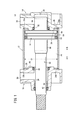
- FIG. 1 is an overall cross sectional view of a fluid pressure cylinder according to a first embodiment of the present invention
- FIG. 2 is an exploded cross sectional view of the fluid pressure cylinder of FIG. 1 ;
- FIG. 3 is an enlarged cross sectional view showing the vicinity of a second positioning ring on a rod cover shown in FIG. 1 ;
- FIG. 4 is an overall cross sectional view showing a condition in which a new cylinder tube having a different diameter is exchanged in the fluid pressure cylinder of FIG. 1 ;
- FIG. 5 is an overall cross sectional view of a fluid pressure cylinder according to a second embodiment of the present invention.
- FIG. 6 is an exploded cross sectional view of the fluid pressure cylinder of FIG. 5 ;
- FIG. 7 is an enlarged cross sectional view showing the vicinity of a second positioning ring on a rod cover shown in FIG. 5 .
- a fluid pressure cylinder 10 includes a cylindrically shaped cylinder tube 12 , a head cover (cover member) 14 mounted on one end of the cylinder tube 12 , a rod cover (cover member) 16 mounted on another end side of the cylinder tube 12 , and a piston 18 , which is disposed displaceably in the interior of the cylinder tube 12 .
- the cylinder tube 12 is made up from a cylindrical body that extends with a substantially constant diameter (cylinder diameter C 1 ) along an axial direction (the direction of arrows A and B). In the interior of the cylinder tube 12 , a cylinder chamber 20 in which the piston 18 is accommodated is formed.
- annular engagement grooves grooves
- First and second positioning rings (positioning members) 26 , 28 are engaged in the engagement grooves 24 a , 24 b.
- the head cover 14 for example, is formed from a metal material with a substantially rectangular shape in cross section, and includes penetrating holes that penetrate in the axial direction (indicated by the arrows A and B) through four corners of the head cover 14 .
- Non-illustrated connecting rods are inserted through the penetrating holes.
- a cavity 30 of a predetermined depth is formed in facing relation to the side of the cylinder tube 12 (in the direction of the arrow A), and a first seal ring 32 is installed in an annular groove formed on an inner circumferential surface of the cavity 30 .
- the cavity 30 is substantially circular in cross section with a substantially constant diameter, and communicates with the cylinder chamber 20 when the head cover 14 is installed on the one end of the cylinder tube 12 .
- a first annular projection 34 which projects toward the side of the cylinder tube 12 (in the direction of the arrow A), is formed on one end surface of the head cover 14 on the side of the cylinder tube 12 (in the direction of the arrow A).
- the first annular projection 34 is formed coaxially with the cavity 30 and in an annular shape on an outer circumferential side of the cavity 30 .
- An annular first positioning ring 26 is mounted on an outer circumferential side of the first annular projection 34 , and the cylinder tube 12 is retained by engagement of an outer circumferential surface of the first positioning ring 26 with the engagement groove 24 a , which is formed on the one end of the cylinder tube 12 . More specifically, as shown in FIGS. 1 and 2 , the first positioning ring 26 is formed such that an inner diameter D 1 thereof (see FIG. 2 ) has substantially the same diameter as the outer diameter of the first annular projection 34 , and an outer diameter D 2 thereof (see FIG. 2 ) has substantially the same diameter as the inner diameter of the engagement groove 24 a in the cylinder tube 12 .
- a first fluid port 36 is provided through which the pressure fluid is supplied and discharged, the first fluid port 36 communicating with the cavity 30 .
- the pressure fluid is introduced into the cavity 30 after the pressure fluid has been supplied to the first fluid port 36 from a non-illustrated pressure fluid supply source.
- the rod cover 16 for example, is formed from a metal material with a substantially rectangular shape in cross section, and includes penetrating holes that penetrate in the axial direction through four corners of the rod cover 16 .
- the connecting rods are inserted through the penetrating holes.
- FIG. 1 in a condition in which the cylinder tube 12 is mounted between the rod cover 16 and the head cover 14 , by screw-engagement of nuts onto both ends of the connecting rods that are inserted through the head cover 14 and the rod cover 16 , the cylinder tube 12 is sandwiched and fixed between the head cover 14 and the rod cover 16 .
- a center portion of the rod cover 16 bulges in a direction away from the cylinder tube 12 .
- a rod hole 38 is formed and penetrates in the axial direction (the direction of arrows A and B).
- a bush 40 and a rod packing 42 are installed on an inner circumferential surface of the rod hole 38 .
- a second seal ring 46 is installed via an annular groove provided in the inner circumferential surface of the rod hole 38 .
- the rod hole 38 communicates with the cylinder chamber 20 .
- a second annular projection 48 which projects toward the side of the cylinder tube 12 (in the direction of the arrow B) is formed on one end surface of the rod cover 16 on the side of the cylinder tube 12 (in the direction of the arrow B).
- the second annular projection 48 is formed in an annular shape on an outer circumferential side of the rod hole 38 coaxially with the rod hole 38 .
- the second annular projection 48 is coaxial with the first annular projection 34 of the head cover 14 , and has the same diameter as the first annular projection 34 of the head cover 14 .
- an annular second positioning ring 28 is installed on the outer circumferential surface of the second annular projection 48 .
- the outer circumferential surface of the second positioning ring 28 engages with the engagement groove 24 b that is formed on the other end of the cylinder tube 12 , thereby retaining the cylinder tube 12 .
- the second positioning ring 28 is formed such that an inner diameter D 1 thereof has substantially the same diameter as the outer diameter of the second annular projection 48 , and an outer diameter D 2 thereof has substantially the same diameter as the inner diameter of the engagement groove 24 b in the cylinder tube 12 .
- the second positioning ring 28 is formed in the same shape as the first positioning ring 26 . Stated otherwise, the first and second positioning rings 26 , 28 are provided as a pair.
- a second fluid port 50 through which the pressure fluid is supplied and discharged is disposed on a side surface of the rod cover 16 , and the second fluid port 50 communicates with the rod hole 38 .
- the pressure fluid supplied from the second fluid port 50 is introduced to the cylinder chamber 20 from the rod hole 38 .
- the piston 18 is formed with substantially the same diameter as the cylinder diameter C 1 of the cylinder tube 12 .
- a piston packing 52 , a magnetic body 54 , and a wear ring 56 are installed via a plurality of annular grooves on the outer circumferential surface of the piston 18 .
- a piston hole (not shown) that penetrates in the axial direction (the direction of arrows A and B) is formed in a center portion of the piston 18 .
- One end of a piston rod 60 is inserted and connected in the piston hole.
- One end of the piston rod 60 is connected to the piston 18 , whereas the other end of the piston rod 60 is inserted through the rod hole 38 and is supported displaceably by the bush 40 .
- first and second cushion rings 64 , 66 are mounted respectively on both end surfaces of the piston 18 .
- the first and second cushion rings 64 , 66 are formed in substantially the same shape.
- the first cushion ring 64 is arranged on one end side of the piston 18 on the side of the head cover 14 (in the direction of the arrow B), and projects outwardly from the one end side.
- the second cushion ring 66 is arranged on the other end side of the piston 18 on the side of the rod cover 16 (in the direction of the arrow A), and is disposed in covering relation to the outer circumferential surface of the piston rod 60 .
- first and second cushion rings 64 , 66 are inserted respectively into the cavity 30 and the rod hole 38 upon displacement of the piston 18 in the axial direction, and by sliding contact of the cushion rings 64 , 66 with the first and second seal rings 32 , 46 , the displacement velocity of the piston 18 is reduced.
- the fluid pressure cylinder 10 according to the first embodiment of the present invention is constructed basically as described above. Next, operations and advantageous effects of the fluid pressure cylinder will be described.
- the condition shown in FIG. 1 in which the piston 18 is displaced toward the side of the head cover 14 (in the direction of the arrow B), and the first cushion ring 64 is accommodated in the cavity 30 , will be referred to as an initial condition.
- a pressure fluid from a non-illustrated pressure fluid supply source is introduced to the first fluid port 36 .
- the second fluid port 50 is placed in a state of being open to atmosphere under a switching action of a non-illustrated switching valve. Consequently, the pressure fluid is supplied into the cavity 30 from the first fluid port 36 , and by means of the pressure fluid, which is introduced into the cylinder chamber 20 from the cavity 30 , the piston 18 is pressed toward the side of the rod cover 16 (in the direction of the arrow A).
- the piston rod 60 also is displaced due to displacement of the piston 18 , and the first cushion ring 64 mounted on the end of the piston rod 60 separates away from the cavity 30 while in sliding contact with the first seal ring 32 .
- the second cushion ring 66 is inserted into the rod hole 38 , whereby the flow rate of the pressure fluid is restricted and is compressed at the interior of the cylinder chamber 20 .
- displacement resistance is created when the piston 18 is displaced, and the displacement velocity of the piston 18 decreases gradually as the piston 18 approaches the displacement end position thereof.
- pressure fluid is supplied to the second fluid port 50 , and the first fluid port 36 is placed in a state of being open to atmosphere under a switching action of a non-illustrated switching valve.
- the pressure fluid is supplied into the rod hole 38 from the second fluid port 50 , and by means of the pressure fluid, which is introduced into the cylinder chamber 20 from the rod hole 38 , the piston 18 is pressed toward the side of the head cover 14 (in the direction of the arrow B).
- piston rod 60 also is displaced due to displacement of the piston 18 , and the second cushion ring 66 mounted on the end of the piston rod 60 separates away from the rod hole 38 while in sliding contact with the second seal ring 46 .
- the first cushion ring 64 is inserted into the cavity 30 , whereby the flow rate of the pressure fluid is restricted and is compressed at the interior of the cylinder chamber 20 .
- displacement resistance is created when the piston 18 is displaced, and the displacement velocity of the piston 18 decreases gradually.
- the initial position is restored (see FIG. 1 ).
- non-illustrated nuts which are screw-engaged with the connecting rods, are loosened, thereby releasing the state of connection of the head cover 14 and the rod cover 16 with the cylinder tube 12 therebetween.
- the head cover 14 and the rod cover 16 are separated mutually in axial directions (the directions of arrows A and B) away from the cylinder tube 12 , followed by the first positioning ring 26 being removed from the first annular projection 34 , and the second positioning ring 28 being removed from the second annular projection 48 .
- a new cylinder tube 12 a having a smaller cylinder diameter C 2 than that of the aforementioned cylinder tube 12 , new first and second positioning rings 26 a , 28 a having outer diameters D 3 that are substantially the same as the cylinder diameter C 2 , and a new piston 18 a formed with substantially the same diameter as the cylinder diameter C 2 are prepared.
- the new first and second positioning rings 26 a , 28 a are formed with inner diameters, which are substantially the same as the diameters (D 1 ) of the aforementioned first and second positioning rings 26 , 28 .
- the length in the axial direction of the new cylinder tube 12 a is the same as the length of the cylinder tube 12 .
- the first positioning ring 26 a is mounted on the first annular projection 34 of the head cover 14
- the second positioning ring 28 a is mounted on the second annular projection 48 of the rod cover 16 , whereby the first and second positioning rings 26 a , 28 a are retained respectively with respect to the head cover 14 and the rod cover 16 .
- the outer diameters D 3 of the first and second positioning rings 26 a , 28 a are smaller than the outer diameters D 2 of the aforementioned first and second positioning rings 26 , 28 (D 3 ⁇ D 2 ).
- one end of the cylinder tube 12 a is inserted over the outer circumference of the first positioning ring 26 a , and the first positioning ring 26 a is placed in engagement with the engagement groove 24 a formed on the inner circumferential surface of the one end of the cylinder tube 12 a , whereby the one end of the cylinder tube 12 a is retained with respect to the head cover 14 .
- the other end of the cylinder tube 12 a is inserted over the outer circumference of the second positioning ring 28 a.
- the cylinder tube 12 and the piston 18 thereof are replaced by a cylinder tube 12 a and a piston 18 a having a smaller cylinder diameter C 2 , and under a displacement action of the piston 18 a , the output force, which is output in the axial direction from the piston rod 60 , is made smaller.
- a cylinder tube 12 having a larger cylinder diameter, a piston 18 having a diameter corresponding to the cylinder diameter, and first and second positioning rings 26 , 28 corresponding to the inner diameter of the cylinder tube 12 are prepared and assembled, whereby the output of the fluid pressure cylinder 10 can easily be increased.
- the output of the fluid pressure cylinder 10 can easily be changed, while the same head cover 14 and rod cover 16 are used.
- first and second positioning rings 26 , 28 function as positioning means for retaining both ends of the cylinder tube 12 radially and coaxially with respect to the head cover 14 and the rod cover 16 .
- the first and second positioning rings 26 , 28 which function as positioning means, are disposed detachably on the first annular projection 34 of the head cover 14 and the second annular projection 48 of the rod cover 16 that constitute the fluid pressure cylinder 10 , and a structure is provided, which is capable of positioning and retaining both ends of the cylinder tube 12 by the outer circumferential surfaces of the first and second positioning rings 26 , 28 .
- equipment costs for preparing a new fluid pressure cylinder can be suppressed, together with enabling a fluid pressure cylinder 10 to be constructed in which a cylinder tube and a piston can be selected to have an optimum diameter (bore diameter) for obtaining a desired output. Owing thereto, for example, compared to the case of using a fluid pressure cylinder having an excessive output capability in relation to the desired output, the fluid pressure cylinder 10 can be operated with minimum consumption of pressure fluid, and energy savings can be realized.
- the fluid pressure cylinder 10 Owing thereto, for example, in the case that the fluid pressure cylinder 10 is used on an assembly line, and is attached to the assembly line via the head cover 14 and the rod cover 16 , the fluid pressure cylinder can be mounted reliably at the prior attachment position without changes to the attachment position (attachment pitch) thereof. As a result, it is possible to easily change the bore diameter of a fluid pressure cylinder 10 used on an assembly line, and to easily and reliably install the fluid pressure cylinder 10 with respect to the assembly line.
- o-rings 22 a , 22 b on both ends of the cylinder tube 12 , which are capable of being placed in abutment with ends of the head cover 14 and the rod cover 16 , even in the case that a different cylinder tube 12 a that differs in cylinder diameter is exchanged, sealing between the cylinder tube 12 a , the head cover 14 , and the rod cover 16 can reliably be performed by the o-rings 22 a , 22 b.
- FIGS. 5 through 7 a fluid pressure cylinder 100 according to a second embodiment is shown in FIGS. 5 through 7 .
- Constituent elements of the fluid pressure cylinder 100 which are the same as those of the fluid pressure cylinder 10 according to the first embodiment, are denoted by the same reference characters, and detailed description of such features is omitted.
- the fluid pressure cylinder 100 according to the second embodiment differs from the fluid pressure cylinder 10 according to the first embodiment, in that first and second positioning rings (positioning members) 104 , 106 are provided on outer circumferential sides on both ends of a cylinder tube 102 , and the cylinder tube 102 is connected to the head cover (cover member) 108 and the rod cover (cover member) 110 through the first and second positioning rings 104 , 106 .
- a first spigot joint 112 is formed on an end surface of the head cover 108
- a second spigot joint 114 is formed on an end surface of the rod cover 110 .
- a first positioning ring 104 is mounted on the first spigot joint 112 , and one end of the cylinder tube 102 is retained thereon.
- a second positioning ring 106 is mounted on the second spigot joint 114 , and the other end of the cylinder tube 102 is retained thereon.
- the first and second positioning rings 104 , 106 are formed in the same shape and include outer circumferential surfaces that are substantially constant in diameter.
- the first and second positioning rings 104 , 106 are formed with spigot surfaces 116 on inner circumferential surfaces of ends of the first and second positioning rings 104 , 106 , the spigot surfaces 116 being fitted on outer circumferential surfaces of the first and second spigot joints 112 , 114 .
- retaining surfaces 118 which are adjacent to the spigot surfaces 116 and project in a radial inward direction with respect to the spigot surfaces 116 , are formed on inner circumferential surfaces of other ends of the first and second positioning rings 104 , 106 . More specifically, the inner circumferential surfaces of the first and second positioning rings 104 , 106 are formed in stepped shapes, such that mutual retaining surfaces 118 thereof are arranged in confronting relation.
- Annular engagement grooves (grooves) 120 a , 120 b which are recessed in a radial inward direction, are formed on the outer circumferential surfaces on both ends of the cylinder tube 102 .
- the retaining surfaces 118 of the first and second positioning rings 104 , 106 are engaged in the engagement grooves 120 a , 120 b .
- the first and second positioning rings 104 , 106 are positioned in the axial direction (the direction of the arrows A and B) respectively with respect to both ends of the cylinder tube 102 .
- first seal members 122 that face toward the outer circumferential side are installed in the engagement grooves 120 a , 120 b , such that by abutment of the first seal members 122 against inner circumferential surfaces of the first and second positioning rings 104 , 106 , leakage of pressure fluid that passes between the cylinder tube 102 and the first and second positioning rings 104 , 106 is prevented.
- Second seal members 124 are disposed, via annular grooves, on end surfaces of the head cover 108 and the rod cover 110 , at locations in abutment with ends of the first and second positioning rings 104 , 106 . By abutment of the ends of the first and second positioning rings 104 , 106 against the second seal members 124 , leakage of pressure fluid that passes between the first positioning ring 104 and the head cover 108 , and between the second positioning ring 106 and the rod cover 110 is prevented.
- the state of connection of the head cover 108 , the cylinder tube 102 , and the rod cover 110 by the connecting rods is released, and after the head cover 108 and the rod cover 110 have been separated, respectively, in axial directions away from the cylinder tube 102 , the first and second positioning rings 104 , 106 are detached from the first and second spigot joints 112 , 114 .
- a new cylinder tube 102 having a different cylinder diameter, and new first and second positioning rings 104 , 106 having different diameters corresponding to the cylinder tube 102 are prepared, and after the first and second positioning rings 104 , 106 have been installed, respectively, on the first spigot joint 112 of the head cover 108 and the second spigot joint 114 of the rod cover 110 , both ends of the cylinder tube 102 are inserted respectively on inner circumferential sides of the retaining surface 118 of the first positioning ring 104 and the retaining surface 118 of the second positioning ring 106 .
- the head cover 108 and the rod cover 110 are made to approach one another mutually such that both ends of the cylinder tube 102 are inserted into the first and second positioning rings 104 , 106 , whereby the retaining surfaces 118 of the first and second positioning rings 104 , 106 come into engagement respectively with the engagement grooves 120 a , 120 b .
- the connecting rods are inserted through the head cover 108 and the rod cover 110 , and by screw-engagement and fastening of nuts on both ends of the connecting rods, the head cover 108 and the rod cover 110 are connected while sandwiching and gripping the cylinder tube 102 therebetween.
- a fluid pressure cylinder 100 having a different bore diameter is constructed in a condition in which both ends of the cylinder tube 102 are retained on the inner circumferential surfaces of the first and second positioning rings 104 , 106 .
- first and second positioning rings 104 , 106 function as positioning means for retaining both ends of the cylinder tube 102 radially and coaxially with respect to the head cover 108 and the rod cover 110 .
- the annular first and second positioning rings 104 , 106 are mounted detachably on the first spigot joint 112 of the head cover 108 and the second spigot joint 114 of the rod cover 110 that make up the fluid pressure cylinder 100 , and both ends of the cylinder tube 102 are inserted into the first and second positioning rings 104 , 106 , whereby the cylinder tube 102 can be positioned and retained in the axial direction.
- equipment costs for preparing a new fluid pressure cylinder can be suppressed, together with enabling a fluid pressure cylinder 100 to be constructed in which the cylinder tube 102 and the piston 18 can be selected to have an optimum diameter for obtaining a desired output. Owing thereto, for example, compared to the case of using a fluid pressure cylinder having an excessive output capability in relation to the desired output, the fluid pressure cylinder 100 can be operated with minimum consumption of pressure fluid, and energy savings can be realized.
- a structure has been described in which the cylinder tube 12 , 102 is sandwiched between the head cover 14 , 108 and the rod cover 16 , 110 , and is fixed by connecting rods.
- the invention is not limited to such a structure.
- a structure may also be provided in which the head cover and the rod cover are connected by screw-engagement with respect to both ends of the cylinder tube.
- the structures of the fluid pressure cylinders are not particularly limited, so long as a structure is provided in which the cylinder tube, the head cover, and the rod cover, as separate elements, can be connected together mutually and coaxially by means of spigot joints.
Landscapes
- Engineering & Computer Science (AREA)
- Physics & Mathematics (AREA)
- Fluid Mechanics (AREA)
- Mechanical Engineering (AREA)
- General Engineering & Computer Science (AREA)
- Actuator (AREA)
Applications Claiming Priority (3)
| Application Number | Priority Date | Filing Date | Title |
|---|---|---|---|
| JP2013-097794 | 2013-05-07 | ||
| JP2013097794A JP6098880B2 (ja) | 2013-05-07 | 2013-05-07 | 流体圧シリンダ |
| PCT/JP2013/081221 WO2014181489A1 (en) | 2013-05-07 | 2013-11-13 | Fluid pressure cylinder |
Publications (2)
| Publication Number | Publication Date |
|---|---|
| US20160076559A1 US20160076559A1 (en) | 2016-03-17 |
| US10184501B2 true US10184501B2 (en) | 2019-01-22 |
Family
ID=49780274
Family Applications (1)
| Application Number | Title | Priority Date | Filing Date |
|---|---|---|---|
| US14/785,906 Expired - Fee Related US10184501B2 (en) | 2013-05-07 | 2013-11-13 | Fluid pressure cylinder |
Country Status (9)
| Country | Link |
|---|---|
| US (1) | US10184501B2 (de) |
| JP (1) | JP6098880B2 (de) |
| KR (1) | KR101846214B1 (de) |
| CN (1) | CN105190054B (de) |
| DE (1) | DE112013007048T5 (de) |
| MX (1) | MX365151B (de) |
| RU (1) | RU2622214C2 (de) |
| TW (1) | TWI554696B (de) |
| WO (1) | WO2014181489A1 (de) |
Cited By (1)
| Publication number | Priority date | Publication date | Assignee | Title |
|---|---|---|---|---|
| US11174881B2 (en) * | 2017-10-05 | 2021-11-16 | Kyb Corporation | Pressure resistant device and fluid pressure cylinder |
Families Citing this family (10)
| Publication number | Priority date | Publication date | Assignee | Title |
|---|---|---|---|---|
| JP6519865B2 (ja) | 2015-06-11 | 2019-05-29 | Smc株式会社 | 流体圧シリンダ |
| JP6403071B2 (ja) | 2015-06-11 | 2018-10-10 | Smc株式会社 | 流体圧シリンダ |
| JP6292483B2 (ja) | 2015-06-11 | 2018-03-14 | Smc株式会社 | 流体圧シリンダ |
| JP6403073B2 (ja) | 2015-06-11 | 2018-10-10 | Smc株式会社 | 流体圧シリンダ |
| JP6403072B2 (ja) | 2015-06-11 | 2018-10-10 | Smc株式会社 | 流体圧シリンダ |
| JP6519864B2 (ja) | 2015-06-11 | 2019-05-29 | Smc株式会社 | 流体圧シリンダ |
| KR101651052B1 (ko) * | 2016-01-04 | 2016-08-24 | 한전케이피에스 주식회사 | 터빈밸브 유압액추에이터 실린더어셈블리 |
| JP6712032B2 (ja) * | 2017-08-30 | 2020-06-17 | Smc株式会社 | バランサシリンダおよびバランサシリンダを用いたワーク搬送装置 |
| JP7009238B2 (ja) * | 2018-01-31 | 2022-01-25 | 株式会社神戸製鋼所 | 往復動圧縮機 |
| DE102021001107A1 (de) | 2021-03-02 | 2022-09-08 | Bümach Engineering International B.V. | Arbeitszylinder und Verfahren zu dessen Herstellung |
Citations (26)
| Publication number | Priority date | Publication date | Assignee | Title |
|---|---|---|---|---|
| US2719510A (en) * | 1951-07-21 | 1955-10-04 | Tomkin Johnson Company | Cushion construction for air cylinders |
| US2755775A (en) | 1954-12-27 | 1956-07-24 | Flick Reedy Corp | Floating cushion for a piston and cylinder device |
| US2853974A (en) * | 1955-10-31 | 1958-09-30 | Westinghouse Air Brake Co | Piston cushioning arrangement for cylinders |
| US3113490A (en) * | 1961-03-16 | 1963-12-10 | Stanley G Harwood | Fluid motor |
| US3598021A (en) * | 1969-04-04 | 1971-08-10 | Allis Chalmers Mfg Co | Hydraulic cylinder assembly |
| JPS56146105U (de) | 1980-04-04 | 1981-11-04 | ||
| JPS57182606U (de) | 1981-05-15 | 1982-11-19 | ||
| US4384511A (en) * | 1980-10-17 | 1983-05-24 | Mefferd Roy J | Hydraulic cylinder |
| WO1988003609A1 (en) | 1986-11-10 | 1988-05-19 | Hydro-Pneumatic Ab | Pneumatic or hydraulic cylinder with built-in velocity control |
| DE4438196A1 (de) | 1994-10-26 | 1995-10-19 | Daimler Benz Ag | Zylinder für fluidische Mittel |
| US5471909A (en) * | 1994-07-26 | 1995-12-05 | Kobelt; Jacob | Fluid cylinder |
| US5601463A (en) * | 1995-06-26 | 1997-02-11 | Kobelt; Jacob | Fluid actuated cylinder with outboard motor mounting |
| US5737998A (en) * | 1996-11-25 | 1998-04-14 | Wang; Chiu Nan | Heavy-load hydraulic or air cylinder |
| US5806406A (en) * | 1994-06-15 | 1998-09-15 | Ab Multidock Hydraulic | Hydraulic piston cylinder |
| DE19843253A1 (de) | 1998-09-10 | 2000-03-23 | Mannesmann Ag | Druckmittelzylinder mit einem Zylinderrohr |
| JP2002147410A (ja) | 2000-11-09 | 2002-05-22 | Izumi Kogyo Kk | シリンダ |
| DE10240093A1 (de) | 2002-08-30 | 2004-04-01 | Dichtelemente Hallite Gmbh | Dichtsystem und Verfahren zum Abdichten |
| DE202004002852U1 (de) | 2004-02-24 | 2004-04-22 | Festo Ag & Co. | Fluidbetätigter Arbeitszylinder |
| US20080134881A1 (en) | 2006-12-06 | 2008-06-12 | Smc Kabushiki Kaisha | Fluid Pressure Cylinder |
| DE102009014817A1 (de) | 2009-03-25 | 2010-09-30 | Festo Ag & Co. Kg | Fluidbetätigter Linearantrieb |
| US20120160093A1 (en) | 2009-09-11 | 2012-06-28 | Smc Corporation | Air cylinder |
| US20120312155A1 (en) * | 2011-06-13 | 2012-12-13 | Mac Valves, Inc. | Piston rod and cylinder seal device for aluminum bath crust breaker |
| US8459618B2 (en) * | 2007-10-22 | 2013-06-11 | Smc Corporation | Humidity conditioning air system for pneumatically driven device |
| US20150159753A1 (en) * | 2011-05-09 | 2015-06-11 | Peter A. Mueller | Cylinder bulkhead holder |
| US20150285277A1 (en) * | 2012-12-20 | 2015-10-08 | Smc Kabushiki Kaisha | Fluid pressure cylinder |
| US20180100523A1 (en) * | 2012-06-04 | 2018-04-12 | Aero Controlex Group Inc. | Blow Down Actuator Assembly Having a Drag Brake |
Family Cites Families (6)
| Publication number | Priority date | Publication date | Assignee | Title |
|---|---|---|---|---|
| DE2319294A1 (de) * | 1973-04-17 | 1974-11-07 | Dictator Tuerschliessergesells | Zylinder, insbesondere arbeitszylinder |
| GB2033536A (en) * | 1978-11-04 | 1980-05-21 | Dowty Boulton Paul Ltd | Piston-and-cylinder device |
| RU2006684C1 (ru) * | 1991-06-17 | 1994-01-30 | Производственное объединение "ГАЗ" | Пневмоцилиндр |
| DE202004007738U1 (de) * | 2004-05-11 | 2004-07-22 | Drumag Gmbh Fluidtechnik | Druckmediumzylinder |
| RU2440244C2 (ru) * | 2010-04-09 | 2012-01-20 | Общество с ограниченной ответственностью "БЛИЗНЕЦЫ" | Гидравлический многоэтажный пресс с гидроцилиндрами подъема и нагревательными плитами |
| RU118377U1 (ru) * | 2012-03-15 | 2012-07-20 | Вячеслав Васильевич Жуков | Гидроцилиндр поршневой |
-
2013
- 2013-05-07 JP JP2013097794A patent/JP6098880B2/ja active Active
- 2013-11-13 WO PCT/JP2013/081221 patent/WO2014181489A1/en active Application Filing
- 2013-11-13 MX MX2015015322A patent/MX365151B/es active IP Right Grant
- 2013-11-13 KR KR1020157032105A patent/KR101846214B1/ko active IP Right Grant
- 2013-11-13 US US14/785,906 patent/US10184501B2/en not_active Expired - Fee Related
- 2013-11-13 RU RU2015147694A patent/RU2622214C2/ru active
- 2013-11-13 DE DE112013007048.0T patent/DE112013007048T5/de not_active Withdrawn
- 2013-11-13 TW TW102141219A patent/TWI554696B/zh not_active IP Right Cessation
- 2013-11-13 CN CN201380076366.0A patent/CN105190054B/zh not_active Expired - Fee Related
Patent Citations (28)
| Publication number | Priority date | Publication date | Assignee | Title |
|---|---|---|---|---|
| US2719510A (en) * | 1951-07-21 | 1955-10-04 | Tomkin Johnson Company | Cushion construction for air cylinders |
| US2755775A (en) | 1954-12-27 | 1956-07-24 | Flick Reedy Corp | Floating cushion for a piston and cylinder device |
| US2853974A (en) * | 1955-10-31 | 1958-09-30 | Westinghouse Air Brake Co | Piston cushioning arrangement for cylinders |
| US3113490A (en) * | 1961-03-16 | 1963-12-10 | Stanley G Harwood | Fluid motor |
| US3598021A (en) * | 1969-04-04 | 1971-08-10 | Allis Chalmers Mfg Co | Hydraulic cylinder assembly |
| JPS56146105U (de) | 1980-04-04 | 1981-11-04 | ||
| US4384511A (en) * | 1980-10-17 | 1983-05-24 | Mefferd Roy J | Hydraulic cylinder |
| JPS57182606U (de) | 1981-05-15 | 1982-11-19 | ||
| WO1988003609A1 (en) | 1986-11-10 | 1988-05-19 | Hydro-Pneumatic Ab | Pneumatic or hydraulic cylinder with built-in velocity control |
| US5806406A (en) * | 1994-06-15 | 1998-09-15 | Ab Multidock Hydraulic | Hydraulic piston cylinder |
| US5471909A (en) * | 1994-07-26 | 1995-12-05 | Kobelt; Jacob | Fluid cylinder |
| DE4438196A1 (de) | 1994-10-26 | 1995-10-19 | Daimler Benz Ag | Zylinder für fluidische Mittel |
| US5601463A (en) * | 1995-06-26 | 1997-02-11 | Kobelt; Jacob | Fluid actuated cylinder with outboard motor mounting |
| US5737998A (en) * | 1996-11-25 | 1998-04-14 | Wang; Chiu Nan | Heavy-load hydraulic or air cylinder |
| DE19843253A1 (de) | 1998-09-10 | 2000-03-23 | Mannesmann Ag | Druckmittelzylinder mit einem Zylinderrohr |
| JP2002147410A (ja) | 2000-11-09 | 2002-05-22 | Izumi Kogyo Kk | シリンダ |
| DE10240093A1 (de) | 2002-08-30 | 2004-04-01 | Dichtelemente Hallite Gmbh | Dichtsystem und Verfahren zum Abdichten |
| DE202004002852U1 (de) | 2004-02-24 | 2004-04-22 | Festo Ag & Co. | Fluidbetätigter Arbeitszylinder |
| US20080134881A1 (en) | 2006-12-06 | 2008-06-12 | Smc Kabushiki Kaisha | Fluid Pressure Cylinder |
| JP2008164163A (ja) | 2006-12-06 | 2008-07-17 | Smc Corp | 流体圧シリンダ |
| US8459618B2 (en) * | 2007-10-22 | 2013-06-11 | Smc Corporation | Humidity conditioning air system for pneumatically driven device |
| DE102009014817A1 (de) | 2009-03-25 | 2010-09-30 | Festo Ag & Co. Kg | Fluidbetätigter Linearantrieb |
| US20120160093A1 (en) | 2009-09-11 | 2012-06-28 | Smc Corporation | Air cylinder |
| CN102575696A (zh) | 2009-09-11 | 2012-07-11 | Smc株式会社 | 气缸 |
| US20150159753A1 (en) * | 2011-05-09 | 2015-06-11 | Peter A. Mueller | Cylinder bulkhead holder |
| US20120312155A1 (en) * | 2011-06-13 | 2012-12-13 | Mac Valves, Inc. | Piston rod and cylinder seal device for aluminum bath crust breaker |
| US20180100523A1 (en) * | 2012-06-04 | 2018-04-12 | Aero Controlex Group Inc. | Blow Down Actuator Assembly Having a Drag Brake |
| US20150285277A1 (en) * | 2012-12-20 | 2015-10-08 | Smc Kabushiki Kaisha | Fluid pressure cylinder |
Non-Patent Citations (7)
| Title |
|---|
| Combined Chinese Office Action and Search Report dated Jun. 2, 2016 in Patent Application No. 201380076366.0 (with English language translation). |
| Combined Taiwanese Office Action and Search Report dated Oct. 15, 2015 in Patent Application No. 102141219 (with Partial English Translation). |
| International Search Report and Written Opinion dated Jul. 4, 2014 in PCT/JP2013/081221 filed Nov. 13, 2013. |
| Japanese Office Action dated Nov. 4, 2015 in Patent Application No. 2013-097794 (with Partial English Translation). |
| Office Action dated Jul. 5, 2016 in Japanese Patent Application No. 2013-097794 (with Partial English translation). |
| Office Action dated Oct. 17, 2017 in German Patent Application No. 11 2013 007 048.0. |
| WO 2012151709 (Mueller, previously cited USPGPUB 20150159753 used as an English translation). * |
Cited By (1)
| Publication number | Priority date | Publication date | Assignee | Title |
|---|---|---|---|---|
| US11174881B2 (en) * | 2017-10-05 | 2021-11-16 | Kyb Corporation | Pressure resistant device and fluid pressure cylinder |
Also Published As
| Publication number | Publication date |
|---|---|
| CN105190054A (zh) | 2015-12-23 |
| US20160076559A1 (en) | 2016-03-17 |
| MX365151B (es) | 2019-05-24 |
| TW201443356A (zh) | 2014-11-16 |
| RU2622214C2 (ru) | 2017-06-13 |
| MX2015015322A (es) | 2016-02-18 |
| CN105190054B (zh) | 2017-09-22 |
| WO2014181489A1 (en) | 2014-11-13 |
| KR101846214B1 (ko) | 2018-04-06 |
| JP2014219038A (ja) | 2014-11-20 |
| TWI554696B (zh) | 2016-10-21 |
| KR20150139613A (ko) | 2015-12-11 |
| RU2015147694A (ru) | 2017-05-15 |
| JP6098880B2 (ja) | 2017-03-22 |
| DE112013007048T5 (de) | 2016-01-21 |
Similar Documents
| Publication | Publication Date | Title |
|---|---|---|
| US10184501B2 (en) | Fluid pressure cylinder | |
| US20080203672A1 (en) | Pressure-energized shaft seal | |
| TWI526642B (zh) | 流體壓力裝置 | |
| US10100928B2 (en) | Floating piston | |
| WO2011111488A1 (ja) | 流体圧シリンダ | |
| CN104968984A (zh) | 紧急分离离合器 | |
| KR102045344B1 (ko) | 유체압 실린더 | |
| US3440930A (en) | Cushion seal device for power cylinders | |
| US10145394B2 (en) | Fluid pressure cylinder | |
| US9752598B2 (en) | Fluid pressure cylinder | |
| US7322273B2 (en) | Piston-piston rod retaining assembly for a hydraulic piston and cylinder unit | |
| JP2008256157A (ja) | 流体圧シリンダ | |
| EP3249240B1 (de) | Vorrichtung mit einem zylinder und einem adapter zur montage des zylinders für einen fluidbetätigten linearantrieb an einem flüssigkeitskanal | |
| JP5374330B2 (ja) | 雌型管継手用キャップ | |
| CN201824221U (zh) | 气动工具旋转接头的结构 | |
| JP2000337315A (ja) | 油圧シリンダのクッション装置 | |
| JP7495755B2 (ja) | 空気圧シリンダ | |
| US20120305135A1 (en) | Fill nipple assembly | |
| KR20210075956A (ko) | 유압실린더용 실링부재 및 결합 방법 | |
| JP2010164066A (ja) | 流体圧シリンダ |
Legal Events
| Date | Code | Title | Description |
|---|---|---|---|
| AS | Assignment |
Owner name: SMC CORPORATION, JAPAN Free format text: ASSIGNMENT OF ASSIGNORS INTEREST;ASSIGNOR:NOMURA, KENJI;REEL/FRAME:036843/0800 Effective date: 20150907 |
|
| STCF | Information on status: patent grant |
Free format text: PATENTED CASE |
|
| FEPP | Fee payment procedure |
Free format text: MAINTENANCE FEE REMINDER MAILED (ORIGINAL EVENT CODE: REM.); ENTITY STATUS OF PATENT OWNER: LARGE ENTITY |
|
| LAPS | Lapse for failure to pay maintenance fees |
Free format text: PATENT EXPIRED FOR FAILURE TO PAY MAINTENANCE FEES (ORIGINAL EVENT CODE: EXP.); ENTITY STATUS OF PATENT OWNER: LARGE ENTITY |
|
| STCH | Information on status: patent discontinuation |
Free format text: PATENT EXPIRED DUE TO NONPAYMENT OF MAINTENANCE FEES UNDER 37 CFR 1.362 |
|
| FP | Lapsed due to failure to pay maintenance fee |
Effective date: 20230122 |