US10144293B2 - Driving force control device and driving force control method - Google Patents
Driving force control device and driving force control method Download PDFInfo
- Publication number
- US10144293B2 US10144293B2 US15/021,197 US201415021197A US10144293B2 US 10144293 B2 US10144293 B2 US 10144293B2 US 201415021197 A US201415021197 A US 201415021197A US 10144293 B2 US10144293 B2 US 10144293B2
- Authority
- US
- United States
- Prior art keywords
- slip ratio
- drive wheel
- driving force
- calculated
- control
- Prior art date
- Legal status (The legal status is an assumption and is not a legal conclusion. Google has not performed a legal analysis and makes no representation as to the accuracy of the status listed.)
- Active, expires
Links
Images




Classifications
-
- B—PERFORMING OPERATIONS; TRANSPORTING
- B60—VEHICLES IN GENERAL
- B60L—PROPULSION OF ELECTRICALLY-PROPELLED VEHICLES; SUPPLYING ELECTRIC POWER FOR AUXILIARY EQUIPMENT OF ELECTRICALLY-PROPELLED VEHICLES; ELECTRODYNAMIC BRAKE SYSTEMS FOR VEHICLES IN GENERAL; MAGNETIC SUSPENSION OR LEVITATION FOR VEHICLES; MONITORING OPERATING VARIABLES OF ELECTRICALLY-PROPELLED VEHICLES; ELECTRIC SAFETY DEVICES FOR ELECTRICALLY-PROPELLED VEHICLES
- B60L3/00—Electric devices on electrically-propelled vehicles for safety purposes; Monitoring operating variables, e.g. speed, deceleration or energy consumption
- B60L3/10—Indicating wheel slip ; Correction of wheel slip
- B60L3/106—Indicating wheel slip ; Correction of wheel slip for maintaining or recovering the adhesion of the drive wheels
-
- B60L11/1803—
-
- B60L11/1868—
-
- B60L11/1877—
-
- B—PERFORMING OPERATIONS; TRANSPORTING
- B60—VEHICLES IN GENERAL
- B60L—PROPULSION OF ELECTRICALLY-PROPELLED VEHICLES; SUPPLYING ELECTRIC POWER FOR AUXILIARY EQUIPMENT OF ELECTRICALLY-PROPELLED VEHICLES; ELECTRODYNAMIC BRAKE SYSTEMS FOR VEHICLES IN GENERAL; MAGNETIC SUSPENSION OR LEVITATION FOR VEHICLES; MONITORING OPERATING VARIABLES OF ELECTRICALLY-PROPELLED VEHICLES; ELECTRIC SAFETY DEVICES FOR ELECTRICALLY-PROPELLED VEHICLES
- B60L15/00—Methods, circuits, or devices for controlling the traction-motor speed of electrically-propelled vehicles
- B60L15/20—Methods, circuits, or devices for controlling the traction-motor speed of electrically-propelled vehicles for control of the vehicle or its driving motor to achieve a desired performance, e.g. speed, torque, programmed variation of speed
-
- B—PERFORMING OPERATIONS; TRANSPORTING
- B60—VEHICLES IN GENERAL
- B60L—PROPULSION OF ELECTRICALLY-PROPELLED VEHICLES; SUPPLYING ELECTRIC POWER FOR AUXILIARY EQUIPMENT OF ELECTRICALLY-PROPELLED VEHICLES; ELECTRODYNAMIC BRAKE SYSTEMS FOR VEHICLES IN GENERAL; MAGNETIC SUSPENSION OR LEVITATION FOR VEHICLES; MONITORING OPERATING VARIABLES OF ELECTRICALLY-PROPELLED VEHICLES; ELECTRIC SAFETY DEVICES FOR ELECTRICALLY-PROPELLED VEHICLES
- B60L15/00—Methods, circuits, or devices for controlling the traction-motor speed of electrically-propelled vehicles
- B60L15/20—Methods, circuits, or devices for controlling the traction-motor speed of electrically-propelled vehicles for control of the vehicle or its driving motor to achieve a desired performance, e.g. speed, torque, programmed variation of speed
- B60L15/2009—Methods, circuits, or devices for controlling the traction-motor speed of electrically-propelled vehicles for control of the vehicle or its driving motor to achieve a desired performance, e.g. speed, torque, programmed variation of speed for braking
-
- B—PERFORMING OPERATIONS; TRANSPORTING
- B60—VEHICLES IN GENERAL
- B60L—PROPULSION OF ELECTRICALLY-PROPELLED VEHICLES; SUPPLYING ELECTRIC POWER FOR AUXILIARY EQUIPMENT OF ELECTRICALLY-PROPELLED VEHICLES; ELECTRODYNAMIC BRAKE SYSTEMS FOR VEHICLES IN GENERAL; MAGNETIC SUSPENSION OR LEVITATION FOR VEHICLES; MONITORING OPERATING VARIABLES OF ELECTRICALLY-PROPELLED VEHICLES; ELECTRIC SAFETY DEVICES FOR ELECTRICALLY-PROPELLED VEHICLES
- B60L3/00—Electric devices on electrically-propelled vehicles for safety purposes; Monitoring operating variables, e.g. speed, deceleration or energy consumption
- B60L3/10—Indicating wheel slip ; Correction of wheel slip
- B60L3/106—Indicating wheel slip ; Correction of wheel slip for maintaining or recovering the adhesion of the drive wheels
- B60L3/108—Indicating wheel slip ; Correction of wheel slip for maintaining or recovering the adhesion of the drive wheels whilst braking, i.e. ABS
-
- B—PERFORMING OPERATIONS; TRANSPORTING
- B60—VEHICLES IN GENERAL
- B60L—PROPULSION OF ELECTRICALLY-PROPELLED VEHICLES; SUPPLYING ELECTRIC POWER FOR AUXILIARY EQUIPMENT OF ELECTRICALLY-PROPELLED VEHICLES; ELECTRODYNAMIC BRAKE SYSTEMS FOR VEHICLES IN GENERAL; MAGNETIC SUSPENSION OR LEVITATION FOR VEHICLES; MONITORING OPERATING VARIABLES OF ELECTRICALLY-PROPELLED VEHICLES; ELECTRIC SAFETY DEVICES FOR ELECTRICALLY-PROPELLED VEHICLES
- B60L50/00—Electric propulsion with power supplied within the vehicle
- B60L50/50—Electric propulsion with power supplied within the vehicle using propulsion power supplied by batteries or fuel cells
- B60L50/51—Electric propulsion with power supplied within the vehicle using propulsion power supplied by batteries or fuel cells characterised by AC-motors
-
- B—PERFORMING OPERATIONS; TRANSPORTING
- B60—VEHICLES IN GENERAL
- B60L—PROPULSION OF ELECTRICALLY-PROPELLED VEHICLES; SUPPLYING ELECTRIC POWER FOR AUXILIARY EQUIPMENT OF ELECTRICALLY-PROPELLED VEHICLES; ELECTRODYNAMIC BRAKE SYSTEMS FOR VEHICLES IN GENERAL; MAGNETIC SUSPENSION OR LEVITATION FOR VEHICLES; MONITORING OPERATING VARIABLES OF ELECTRICALLY-PROPELLED VEHICLES; ELECTRIC SAFETY DEVICES FOR ELECTRICALLY-PROPELLED VEHICLES
- B60L50/00—Electric propulsion with power supplied within the vehicle
- B60L50/50—Electric propulsion with power supplied within the vehicle using propulsion power supplied by batteries or fuel cells
- B60L50/60—Electric propulsion with power supplied within the vehicle using propulsion power supplied by batteries or fuel cells using power supplied by batteries
- B60L50/66—Arrangements of batteries
-
- B—PERFORMING OPERATIONS; TRANSPORTING
- B60—VEHICLES IN GENERAL
- B60L—PROPULSION OF ELECTRICALLY-PROPELLED VEHICLES; SUPPLYING ELECTRIC POWER FOR AUXILIARY EQUIPMENT OF ELECTRICALLY-PROPELLED VEHICLES; ELECTRODYNAMIC BRAKE SYSTEMS FOR VEHICLES IN GENERAL; MAGNETIC SUSPENSION OR LEVITATION FOR VEHICLES; MONITORING OPERATING VARIABLES OF ELECTRICALLY-PROPELLED VEHICLES; ELECTRIC SAFETY DEVICES FOR ELECTRICALLY-PROPELLED VEHICLES
- B60L58/00—Methods or circuit arrangements for monitoring or controlling batteries or fuel cells, specially adapted for electric vehicles
- B60L58/10—Methods or circuit arrangements for monitoring or controlling batteries or fuel cells, specially adapted for electric vehicles for monitoring or controlling batteries
- B60L58/18—Methods or circuit arrangements for monitoring or controlling batteries or fuel cells, specially adapted for electric vehicles for monitoring or controlling batteries of two or more battery modules
- B60L58/20—Methods or circuit arrangements for monitoring or controlling batteries or fuel cells, specially adapted for electric vehicles for monitoring or controlling batteries of two or more battery modules having different nominal voltages
-
- B—PERFORMING OPERATIONS; TRANSPORTING
- B60—VEHICLES IN GENERAL
- B60L—PROPULSION OF ELECTRICALLY-PROPELLED VEHICLES; SUPPLYING ELECTRIC POWER FOR AUXILIARY EQUIPMENT OF ELECTRICALLY-PROPELLED VEHICLES; ELECTRODYNAMIC BRAKE SYSTEMS FOR VEHICLES IN GENERAL; MAGNETIC SUSPENSION OR LEVITATION FOR VEHICLES; MONITORING OPERATING VARIABLES OF ELECTRICALLY-PROPELLED VEHICLES; ELECTRIC SAFETY DEVICES FOR ELECTRICALLY-PROPELLED VEHICLES
- B60L7/00—Electrodynamic brake systems for vehicles in general
- B60L7/10—Dynamic electric regenerative braking
- B60L7/14—Dynamic electric regenerative braking for vehicles propelled by AC motors
-
- B—PERFORMING OPERATIONS; TRANSPORTING
- B60—VEHICLES IN GENERAL
- B60T—VEHICLE BRAKE CONTROL SYSTEMS OR PARTS THEREOF; BRAKE CONTROL SYSTEMS OR PARTS THEREOF, IN GENERAL; ARRANGEMENT OF BRAKING ELEMENTS ON VEHICLES IN GENERAL; PORTABLE DEVICES FOR PREVENTING UNWANTED MOVEMENT OF VEHICLES; VEHICLE MODIFICATIONS TO FACILITATE COOLING OF BRAKES
- B60T8/00—Arrangements for adjusting wheel-braking force to meet varying vehicular or ground-surface conditions, e.g. limiting or varying distribution of braking force
- B60T8/17—Using electrical or electronic regulation means to control braking
- B60T8/175—Brake regulation specially adapted to prevent excessive wheel spin during vehicle acceleration, e.g. for traction control
-
- B—PERFORMING OPERATIONS; TRANSPORTING
- B60—VEHICLES IN GENERAL
- B60T—VEHICLE BRAKE CONTROL SYSTEMS OR PARTS THEREOF; BRAKE CONTROL SYSTEMS OR PARTS THEREOF, IN GENERAL; ARRANGEMENT OF BRAKING ELEMENTS ON VEHICLES IN GENERAL; PORTABLE DEVICES FOR PREVENTING UNWANTED MOVEMENT OF VEHICLES; VEHICLE MODIFICATIONS TO FACILITATE COOLING OF BRAKES
- B60T8/00—Arrangements for adjusting wheel-braking force to meet varying vehicular or ground-surface conditions, e.g. limiting or varying distribution of braking force
- B60T8/17—Using electrical or electronic regulation means to control braking
- B60T8/176—Brake regulation specially adapted to prevent excessive wheel slip during vehicle deceleration, e.g. ABS
- B60T8/1763—Brake regulation specially adapted to prevent excessive wheel slip during vehicle deceleration, e.g. ABS responsive to the coefficient of friction between the wheels and the ground surface
- B60T8/17636—Microprocessor-based systems
-
- B—PERFORMING OPERATIONS; TRANSPORTING
- B60—VEHICLES IN GENERAL
- B60W—CONJOINT CONTROL OF VEHICLE SUB-UNITS OF DIFFERENT TYPE OR DIFFERENT FUNCTION; CONTROL SYSTEMS SPECIALLY ADAPTED FOR HYBRID VEHICLES; ROAD VEHICLE DRIVE CONTROL SYSTEMS FOR PURPOSES NOT RELATED TO THE CONTROL OF A PARTICULAR SUB-UNIT
- B60W10/00—Conjoint control of vehicle sub-units of different type or different function
- B60W10/04—Conjoint control of vehicle sub-units of different type or different function including control of propulsion units
- B60W10/08—Conjoint control of vehicle sub-units of different type or different function including control of propulsion units including control of electric propulsion units, e.g. motors or generators
-
- B—PERFORMING OPERATIONS; TRANSPORTING
- B60—VEHICLES IN GENERAL
- B60W—CONJOINT CONTROL OF VEHICLE SUB-UNITS OF DIFFERENT TYPE OR DIFFERENT FUNCTION; CONTROL SYSTEMS SPECIALLY ADAPTED FOR HYBRID VEHICLES; ROAD VEHICLE DRIVE CONTROL SYSTEMS FOR PURPOSES NOT RELATED TO THE CONTROL OF A PARTICULAR SUB-UNIT
- B60W10/00—Conjoint control of vehicle sub-units of different type or different function
- B60W10/18—Conjoint control of vehicle sub-units of different type or different function including control of braking systems
- B60W10/184—Conjoint control of vehicle sub-units of different type or different function including control of braking systems with wheel brakes
-
- B—PERFORMING OPERATIONS; TRANSPORTING
- B60—VEHICLES IN GENERAL
- B60W—CONJOINT CONTROL OF VEHICLE SUB-UNITS OF DIFFERENT TYPE OR DIFFERENT FUNCTION; CONTROL SYSTEMS SPECIALLY ADAPTED FOR HYBRID VEHICLES; ROAD VEHICLE DRIVE CONTROL SYSTEMS FOR PURPOSES NOT RELATED TO THE CONTROL OF A PARTICULAR SUB-UNIT
- B60W30/00—Purposes of road vehicle drive control systems not related to the control of a particular sub-unit, e.g. of systems using conjoint control of vehicle sub-units
- B60W30/18—Propelling the vehicle
- B60W30/18172—Preventing, or responsive to skidding of wheels
-
- B—PERFORMING OPERATIONS; TRANSPORTING
- B60—VEHICLES IN GENERAL
- B60L—PROPULSION OF ELECTRICALLY-PROPELLED VEHICLES; SUPPLYING ELECTRIC POWER FOR AUXILIARY EQUIPMENT OF ELECTRICALLY-PROPELLED VEHICLES; ELECTRODYNAMIC BRAKE SYSTEMS FOR VEHICLES IN GENERAL; MAGNETIC SUSPENSION OR LEVITATION FOR VEHICLES; MONITORING OPERATING VARIABLES OF ELECTRICALLY-PROPELLED VEHICLES; ELECTRIC SAFETY DEVICES FOR ELECTRICALLY-PROPELLED VEHICLES
- B60L2210/00—Converter types
- B60L2210/10—DC to DC converters
-
- B—PERFORMING OPERATIONS; TRANSPORTING
- B60—VEHICLES IN GENERAL
- B60L—PROPULSION OF ELECTRICALLY-PROPELLED VEHICLES; SUPPLYING ELECTRIC POWER FOR AUXILIARY EQUIPMENT OF ELECTRICALLY-PROPELLED VEHICLES; ELECTRODYNAMIC BRAKE SYSTEMS FOR VEHICLES IN GENERAL; MAGNETIC SUSPENSION OR LEVITATION FOR VEHICLES; MONITORING OPERATING VARIABLES OF ELECTRICALLY-PROPELLED VEHICLES; ELECTRIC SAFETY DEVICES FOR ELECTRICALLY-PROPELLED VEHICLES
- B60L2240/00—Control parameters of input or output; Target parameters
- B60L2240/10—Vehicle control parameters
- B60L2240/12—Speed
-
- B—PERFORMING OPERATIONS; TRANSPORTING
- B60—VEHICLES IN GENERAL
- B60L—PROPULSION OF ELECTRICALLY-PROPELLED VEHICLES; SUPPLYING ELECTRIC POWER FOR AUXILIARY EQUIPMENT OF ELECTRICALLY-PROPELLED VEHICLES; ELECTRODYNAMIC BRAKE SYSTEMS FOR VEHICLES IN GENERAL; MAGNETIC SUSPENSION OR LEVITATION FOR VEHICLES; MONITORING OPERATING VARIABLES OF ELECTRICALLY-PROPELLED VEHICLES; ELECTRIC SAFETY DEVICES FOR ELECTRICALLY-PROPELLED VEHICLES
- B60L2240/00—Control parameters of input or output; Target parameters
- B60L2240/40—Drive Train control parameters
- B60L2240/42—Drive Train control parameters related to electric machines
- B60L2240/423—Torque
-
- B—PERFORMING OPERATIONS; TRANSPORTING
- B60—VEHICLES IN GENERAL
- B60L—PROPULSION OF ELECTRICALLY-PROPELLED VEHICLES; SUPPLYING ELECTRIC POWER FOR AUXILIARY EQUIPMENT OF ELECTRICALLY-PROPELLED VEHICLES; ELECTRODYNAMIC BRAKE SYSTEMS FOR VEHICLES IN GENERAL; MAGNETIC SUSPENSION OR LEVITATION FOR VEHICLES; MONITORING OPERATING VARIABLES OF ELECTRICALLY-PROPELLED VEHICLES; ELECTRIC SAFETY DEVICES FOR ELECTRICALLY-PROPELLED VEHICLES
- B60L2240/00—Control parameters of input or output; Target parameters
- B60L2240/40—Drive Train control parameters
- B60L2240/46—Drive Train control parameters related to wheels
- B60L2240/461—Speed
-
- B—PERFORMING OPERATIONS; TRANSPORTING
- B60—VEHICLES IN GENERAL
- B60L—PROPULSION OF ELECTRICALLY-PROPELLED VEHICLES; SUPPLYING ELECTRIC POWER FOR AUXILIARY EQUIPMENT OF ELECTRICALLY-PROPELLED VEHICLES; ELECTRODYNAMIC BRAKE SYSTEMS FOR VEHICLES IN GENERAL; MAGNETIC SUSPENSION OR LEVITATION FOR VEHICLES; MONITORING OPERATING VARIABLES OF ELECTRICALLY-PROPELLED VEHICLES; ELECTRIC SAFETY DEVICES FOR ELECTRICALLY-PROPELLED VEHICLES
- B60L2240/00—Control parameters of input or output; Target parameters
- B60L2240/40—Drive Train control parameters
- B60L2240/46—Drive Train control parameters related to wheels
- B60L2240/465—Slip
-
- B—PERFORMING OPERATIONS; TRANSPORTING
- B60—VEHICLES IN GENERAL
- B60L—PROPULSION OF ELECTRICALLY-PROPELLED VEHICLES; SUPPLYING ELECTRIC POWER FOR AUXILIARY EQUIPMENT OF ELECTRICALLY-PROPELLED VEHICLES; ELECTRODYNAMIC BRAKE SYSTEMS FOR VEHICLES IN GENERAL; MAGNETIC SUSPENSION OR LEVITATION FOR VEHICLES; MONITORING OPERATING VARIABLES OF ELECTRICALLY-PROPELLED VEHICLES; ELECTRIC SAFETY DEVICES FOR ELECTRICALLY-PROPELLED VEHICLES
- B60L2250/00—Driver interactions
- B60L2250/16—Driver interactions by display
-
- B—PERFORMING OPERATIONS; TRANSPORTING
- B60—VEHICLES IN GENERAL
- B60L—PROPULSION OF ELECTRICALLY-PROPELLED VEHICLES; SUPPLYING ELECTRIC POWER FOR AUXILIARY EQUIPMENT OF ELECTRICALLY-PROPELLED VEHICLES; ELECTRODYNAMIC BRAKE SYSTEMS FOR VEHICLES IN GENERAL; MAGNETIC SUSPENSION OR LEVITATION FOR VEHICLES; MONITORING OPERATING VARIABLES OF ELECTRICALLY-PROPELLED VEHICLES; ELECTRIC SAFETY DEVICES FOR ELECTRICALLY-PROPELLED VEHICLES
- B60L2250/00—Driver interactions
- B60L2250/26—Driver interactions by pedal actuation
-
- B—PERFORMING OPERATIONS; TRANSPORTING
- B60—VEHICLES IN GENERAL
- B60L—PROPULSION OF ELECTRICALLY-PROPELLED VEHICLES; SUPPLYING ELECTRIC POWER FOR AUXILIARY EQUIPMENT OF ELECTRICALLY-PROPELLED VEHICLES; ELECTRODYNAMIC BRAKE SYSTEMS FOR VEHICLES IN GENERAL; MAGNETIC SUSPENSION OR LEVITATION FOR VEHICLES; MONITORING OPERATING VARIABLES OF ELECTRICALLY-PROPELLED VEHICLES; ELECTRIC SAFETY DEVICES FOR ELECTRICALLY-PROPELLED VEHICLES
- B60L2260/00—Operating Modes
- B60L2260/20—Drive modes; Transition between modes
- B60L2260/26—Transition between different drive modes
-
- B—PERFORMING OPERATIONS; TRANSPORTING
- B60—VEHICLES IN GENERAL
- B60L—PROPULSION OF ELECTRICALLY-PROPELLED VEHICLES; SUPPLYING ELECTRIC POWER FOR AUXILIARY EQUIPMENT OF ELECTRICALLY-PROPELLED VEHICLES; ELECTRODYNAMIC BRAKE SYSTEMS FOR VEHICLES IN GENERAL; MAGNETIC SUSPENSION OR LEVITATION FOR VEHICLES; MONITORING OPERATING VARIABLES OF ELECTRICALLY-PROPELLED VEHICLES; ELECTRIC SAFETY DEVICES FOR ELECTRICALLY-PROPELLED VEHICLES
- B60L2270/00—Problem solutions or means not otherwise provided for
- B60L2270/10—Emission reduction
- B60L2270/14—Emission reduction of noise
- B60L2270/145—Structure borne vibrations
-
- B—PERFORMING OPERATIONS; TRANSPORTING
- B60—VEHICLES IN GENERAL
- B60W—CONJOINT CONTROL OF VEHICLE SUB-UNITS OF DIFFERENT TYPE OR DIFFERENT FUNCTION; CONTROL SYSTEMS SPECIALLY ADAPTED FOR HYBRID VEHICLES; ROAD VEHICLE DRIVE CONTROL SYSTEMS FOR PURPOSES NOT RELATED TO THE CONTROL OF A PARTICULAR SUB-UNIT
- B60W2540/00—Input parameters relating to occupants
- B60W2540/18—Steering angle
-
- B60W2550/148—
-
- B—PERFORMING OPERATIONS; TRANSPORTING
- B60—VEHICLES IN GENERAL
- B60W—CONJOINT CONTROL OF VEHICLE SUB-UNITS OF DIFFERENT TYPE OR DIFFERENT FUNCTION; CONTROL SYSTEMS SPECIALLY ADAPTED FOR HYBRID VEHICLES; ROAD VEHICLE DRIVE CONTROL SYSTEMS FOR PURPOSES NOT RELATED TO THE CONTROL OF A PARTICULAR SUB-UNIT
- B60W2552/00—Input parameters relating to infrastructure
- B60W2552/40—Coefficient of friction
-
- B—PERFORMING OPERATIONS; TRANSPORTING
- B60—VEHICLES IN GENERAL
- B60W—CONJOINT CONTROL OF VEHICLE SUB-UNITS OF DIFFERENT TYPE OR DIFFERENT FUNCTION; CONTROL SYSTEMS SPECIALLY ADAPTED FOR HYBRID VEHICLES; ROAD VEHICLE DRIVE CONTROL SYSTEMS FOR PURPOSES NOT RELATED TO THE CONTROL OF A PARTICULAR SUB-UNIT
- B60W2720/00—Output or target parameters relating to overall vehicle dynamics
- B60W2720/26—Wheel slip
-
- Y—GENERAL TAGGING OF NEW TECHNOLOGICAL DEVELOPMENTS; GENERAL TAGGING OF CROSS-SECTIONAL TECHNOLOGIES SPANNING OVER SEVERAL SECTIONS OF THE IPC; TECHNICAL SUBJECTS COVERED BY FORMER USPC CROSS-REFERENCE ART COLLECTIONS [XRACs] AND DIGESTS
- Y02—TECHNOLOGIES OR APPLICATIONS FOR MITIGATION OR ADAPTATION AGAINST CLIMATE CHANGE
- Y02T—CLIMATE CHANGE MITIGATION TECHNOLOGIES RELATED TO TRANSPORTATION
- Y02T10/00—Road transport of goods or passengers
- Y02T10/60—Other road transportation technologies with climate change mitigation effect
- Y02T10/64—Electric machine technologies in electromobility
-
- Y02T10/645—
-
- Y—GENERAL TAGGING OF NEW TECHNOLOGICAL DEVELOPMENTS; GENERAL TAGGING OF CROSS-SECTIONAL TECHNOLOGIES SPANNING OVER SEVERAL SECTIONS OF THE IPC; TECHNICAL SUBJECTS COVERED BY FORMER USPC CROSS-REFERENCE ART COLLECTIONS [XRACs] AND DIGESTS
- Y02—TECHNOLOGIES OR APPLICATIONS FOR MITIGATION OR ADAPTATION AGAINST CLIMATE CHANGE
- Y02T—CLIMATE CHANGE MITIGATION TECHNOLOGIES RELATED TO TRANSPORTATION
- Y02T10/00—Road transport of goods or passengers
- Y02T10/60—Other road transportation technologies with climate change mitigation effect
- Y02T10/70—Energy storage systems for electromobility, e.g. batteries
-
- Y02T10/7005—
-
- Y02T10/7066—
-
- Y—GENERAL TAGGING OF NEW TECHNOLOGICAL DEVELOPMENTS; GENERAL TAGGING OF CROSS-SECTIONAL TECHNOLOGIES SPANNING OVER SEVERAL SECTIONS OF THE IPC; TECHNICAL SUBJECTS COVERED BY FORMER USPC CROSS-REFERENCE ART COLLECTIONS [XRACs] AND DIGESTS
- Y02—TECHNOLOGIES OR APPLICATIONS FOR MITIGATION OR ADAPTATION AGAINST CLIMATE CHANGE
- Y02T—CLIMATE CHANGE MITIGATION TECHNOLOGIES RELATED TO TRANSPORTATION
- Y02T10/00—Road transport of goods or passengers
- Y02T10/60—Other road transportation technologies with climate change mitigation effect
- Y02T10/72—Electric energy management in electromobility
-
- Y02T10/7216—
-
- Y02T10/7275—
Definitions
- the present invention relates to a driving force control device for a vehicle.
- Patent Literature 1 a technology described in Patent Literature 1 is known as a driving force control device for a vehicle.
- a driving force control device for a vehicle.
- this vehicle in order to suppress a drive slip of a drive wheel, in an area including a ⁇ peak of a ⁇ -s characteristic curve representing a relationship between a slip ratio s and a friction coefficient ⁇ between a tire and a road surface, a driving torque is controlled. As a result, both a stability performance and a traction performance are achieved.
- the present invention has been made in view of the above-mentioned problem, and therefore has an object to provide a driving force control device and a driving force control method that are capable of stabilizing the vehicle behavior when the driving torque of the drive wheel is controlled.
- a driving force control device when slip suppression control is carried out to decrease a driving torque of a drive source that is connected to a drive wheel of a vehicle via a speed reduction mechanism and a drive shaft, and is configured to generate a torque for braking or driving the drive wheel, to thereby suppress a slip state of the drive wheel, the driving torque of the drive source is controlled so that a slip ratio of the drive wheel is in an area of the slip ratio smaller than a slip ratio corresponding to a peak value of a road surface friction coefficient in a characteristic of the road surface friction coefficient with respect to the slip ratio.
- FIG. 1 is a system diagram for illustrating a configuration of an electric vehicle according to a first embodiment of the present invention.
- FIG. 2 is a schematic diagram for illustrating a connection state among various controllers according to the first embodiment.
- FIG. 3 is a schematic diagram for illustrating a connection state among various controllers according to a comparative example.
- FIG. 4 is a control block diagram for illustrating contents of information to be transmitted or received by the respective controllers according to the first embodiment.
- FIG. 5 is a control block diagram for illustrating a request of each of a vehicle controller and a traction control provided in a brake controller, and a control content to be carried out by a motor controller according to the first embodiment.
- FIG. 6 is a flowchart for illustrating command value selection processing according to the first embodiment.
- FIG. 7 is a control block diagram for illustrating vibration suppression control torque command value calculation processing according to the first embodiment.
- FIG. 8 is a control block diagram for illustrating slip control to be carried out by a traction control unit according to the first embodiment.
- FIG. 9 is a control block diagram for illustrating target drive wheel speed reference value calculation processing according to the first embodiment.
- FIG. 10 is a control block diagram for illustrating target drive wheel speed calculation processing according to the first embodiment.
- FIG. 11 is a control block diagram for illustrating acceleration slip control torque calculation processing according to the first embodiment.
- FIG. 12 is a control block diagram for illustrating slip control torque command value calculation processing according to the first embodiment.
- FIG. 13 is a control block diagram for illustrating acceleration slip control start speed calculation processing according to the first embodiment.
- FIG. 14 is a control block diagram for illustrating acceleration slip control end speed calculation processing according to the first embodiment.
- FIG. 15 is a control block diagram for illustrating acceleration slip control flag calculation processing according to the first embodiment.
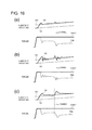
- FIG. 16 are time charts for illustrating a relationship between the number of rotations and a torque when drive slip control is carried out.
- FIG. 17 is a characteristic chart for illustrating a relationship between a slip ratio and a driving force when slip control is carried out in a comparative example.
- FIG. 18 is a characteristic chart for illustrating the relationship between the slip ratio and the driving force when a ⁇ jump occurs only on a right wheel, and the slip control is carried out according to the first embodiment.
- FIG. 19 is a time chart for illustrating a relationship between left and right drive wheel speeds and a motor torque command value when the slip control is carried out according to the first embodiment.
- FIG. 1 is a system diagram for illustrating a configuration of an electric vehicle according to a first embodiment of the present invention.
- the electric vehicle is a front wheel drive vehicle, and includes front wheels FL and FR, which are drive wheels, and rear wheels RL and RR, which are driven wheels.
- a wheel cylinder W/C (FL), W/C (FR), W/C (RL), or W/C (RR) (also simply referred to as W/C), which is configured to generate a friction braking force by pressing a brake pad to a brake rotor configured to integrally rotate with a tire
- a wheel speed sensor 9 (FL), 9 (FR), 9 (RL), or 9 (RR) (also simply referred to as 9 ), which is configured to detect a wheel speed of each wheel, are provided.
- a hydraulic unit 5 is connected via a hydraulic pipe 5 a.
- the hydraulic unit 5 includes a plurality of solenoid valves, a reservoir, a pump motor, and a brake controller 50 , and is configured to control, based on a command from the brake controller 50 , drive states of the various solenoid valves and the pump motor, thereby controlling wheel cylinder hydraulic pressures for the respective wheels.
- the hydraulic unit 5 may be a widely known brake-by-wire unit, or a brake unit including a hydraulic circuit capable of carrying out vehicle stability control, and is thus not particularly limited.
- a resolver 2 configured to detect a motor rotational angle is provided.
- a differential gear 3 is connected via a speed reduction mechanism 3 a , and, to a drive shaft 4 connected to the differential gear 3 , the front wheels FL and FR are connected.
- a high-voltage battery 6 configured to supply an electric power for driving to the electric motor 1 , or recover a regenerative electric power
- a battery controller 60 configured to monitor and control a battery state of the high-voltage battery 6 are mounted.
- An inverter 10 interposed between the high-voltage battery 6 and the electric motor 1 is controlled by a motor controller 100 .
- an accessory battery 8 is connected via a DC-DC converter 7 (component), and the accessory battery 8 functions as a power supply for driving of the hydraulic unit 5 .
- a CAN communication line is provided, which is an onboard communication line to which a plurality of controllers installed on the vehicle are connected.
- the brake controller 50 , a vehicle controller 110 , the battery controller 60 , and the like are connected for mutual information communication.
- a power steering controller 20 configured to control a power steering device configured to assist a steering operation by a driver and a meter controller 22 configured to control a speedometer configured to indicate a vehicle speed, which are not shown in FIG. 1 , are connected to the CAN communication line.
- a steering angle sensor 21 configured to detect a steering angle of a steering wheel is provided.
- FIG. 2 is a schematic diagram for illustrating a connection state of the various controllers according to the first embodiment.
- the battery controller 60 , the motor controller 100 , the DC-DC converter 7 , and the brake controller 50 which are configured to control a torque state acting between each of the drive wheels and the road surface, are grouped into a powertrain system, and are connected to a first CAN bus CAN 1 (first communication device).
- a chassis system including the power steering controller 20 and the meter controller 22 is connected to a second CAN bus CAN 2 (second communication device).
- the first CAN bus CAN 1 and the second CAN bus CAN 2 are connected with each other via a connection bus CAN 3 .
- the vehicle controller 110 On the connection bus CAN 3 , the vehicle controller 110 is provided, and information transmitted or received on the first CAN bus CAN 1 is received by the vehicle controller 110 on the connection bus CAN 3 , and is then output to the second CAN bus CAN 2 .
- information transmitted or received on the second CAN bus CAN 2 is received by the vehicle controller 110 on the connection bus CAN 3 , and is then output to the first CAN bus CAN 1 .
- FIG. 3 is a schematic diagram for illustrating the connection state among the various controllers according to the comparative example.
- the brake controller 50 is connected to the second CAN bus CAN 2 . This is because, hitherto, the control for the brake system is included in control for the chassis system, and is thus not considered to be included in control for the powertrain system.
- the respective systems such as the powertrain system, the brake system, a steering system, and a suspension system are often respectively developed as individual systems.
- the unification is carried out by connection to a CAN communication line.
- the CAN communication line is limited in the number of controllers that can be connected, but can easily connect a plurality of controllers to be grouped.
- the controllers are divided into a group in which the controllers in the chassis system are connected as a whole and a group in which the controllers in the powertrain system are connected as a whole, and, on the connection bus configured to connect between the respective groups, the vehicle controller is provided so as to control the entire vehicle.
- a sufficient travel performance is hard to be secured in some cases.
- a drive slip may be generated.
- the brake controller 50 requests the vehicle controller 110 to suppress the slip state. Then, the vehicle controller 110 outputs a request such as a torque decrease to the motor controller 100 based on the request received from the brake controller 50 .
- the brake controller 50 is a system configured to control the torque between the drive wheel and the road surface
- the brake controller 50 is included in the powertrain system, and is connected to the first CAN communication line CAN 1 .
- the vehicle speed information and the like output from the brake controller 50 are slightly delayed in the timing to transmit to the second CAN bus CAN 2 , but the vehicle speed does not change abruptly due to the magnitude of the inertia of the vehicle, and there poses no problem.
- the responsiveness of the torque control is much better than that of the internal combustion engine, and more precise drive wheel slip control can be carried out.
- the responsiveness of the CAN communication line has come to pose a problem.
- the vehicle controller 110 configured to control the entire vehicle to monitor and control the entirety, but if such an excessive centralization that, after all information is gathered, all commands are issued to the respective controllers is carried out, a calculation load on the vehicle controller 110 increases, and an extremely expensive controller is necessary. Moreover, the vehicle controller 110 also considers information on a low communication speed, and then outputs a command, and thus, even if an expensive vehicle controller 110 is employed, a vehicle system good in the responsiveness cannot be built. Moreover, it is conceivable to transmit or receive all information quickly, but an increase in a communication speed is a specification change influencing all other controllers connected to this communication line, and it is very difficult to increase the entire communication speed in a complex system.
- the configuration of the CAN communication line is divided into the first CAN bus CAN 1 and the second CAN bus CAN 2 .
- the vehicle controller 110 does not output all the commands, but controllers on levels lower than the vehicle controller 110 make determinations and carry out control to some extent is constructed.
- the brake request output from the brake controller 50 can directly be transmitted to the motor controller 100 is provided.
- the motor controller 100 can read, in addition to the normal torque request from the vehicle controller 110 , the brake request from the brake controller 50 , and can output the final motor torque command value depending on the travel state is provided.
- FIG. 4 is a control block diagram for illustrating contents of information to be transmitted or received by the respective controllers according to the first embodiment.
- the vehicle controller 110 inputs accelerator pedal position information and shift position information, calculates a first torque command value based on a basic driver request torque and other results of control processing, and outputs the first torque command value to the motor controller 100 and the brake controller 50 .
- the brake controller 50 inputs an on/off state of a brake switch representing a brake pedal operation state and a wheel speed signal of each wheel, and outputs, for example, a second torque command value based on a request from a traction control, a brake device state representing whether or not the hydraulic unit 5 and the brake controller 50 are normally operating, and a torque increase/decrease request such as an increase, a decrease, or no increase/decrease in response to a driver request.
- the motor controller 100 when the brake device state is normal, and when a result of a comparison between the first torque command value and the second value command value matches the torque increase/decrease request, the second torque command value from the brake controller 50 is employed, and when these conditions are not satisfied, the first torque command value is employed. As a result of these determinations, even if a problem such as a communication failure occurs, the motor controller 100 is prevented from operating against the intentions of the driver and the brake controller 50 .
- FIG. 5 is a control block diagram for illustrating a request of each of the vehicle controller and the traction control provided in the brake controller, and a control content to be carried out by the motor controller according to the first embodiment.
- a driver request torque command value calculation unit 111 in the vehicle controller 110 calculates the driver request torque (first torque command value) based on an accelerator pedal opening degree and a shift position, and outputs the driver request torque to the motor controller 100 .
- a traction control unit 51 in the brake controller 50 inputs the wheel speed information from the wheel speed sensors 9 , the steering angle information from the steering angle sensor, and an actual motor torque output by the electric motor 1 .
- the traction control unit 51 determines whether or not the drive wheel is in the drive slip state. When the drive wheel is in the drive slip state, the traction control unit 51 outputs the traction control torque (second torque command value) for suppressing the drive slip, and outputs a control flag representing the control content carried out in the brake controller 50 to the motor controller 100 .
- the motor controller 100 includes a changeover switch 101 configured to switch, based on the control flag, the command value to be selected between the driver request torque and the traction control torque, a torque addition unit 102 configured to add a vibration suppression control torque to be described later to a switched torque command value TMCIN*, thereby outputting a final torque command value, a motor current control unit 105 configured to output an inverter drive signal to the inverter 10 in order to control the current to be supplied to the electric motor 1 based on the final torque command value, a vibration suppression control information calculation unit 103 configured to calculate a vibration suppression control gain and a vibration suppression control restriction value for suppressing a vibration of a drive system to be generated in the powertrain system, and a vibration suppression control unit 104 configured to calculate, based on the calculated vibration suppression control information and the motor rotational speed, a vibration suppression control torque for suppressing the vibration of the powertrain system.
- FIG. 6 is a flowchart for illustrating the command value selection processing according to the first embodiment.
- the changeover switch 101 as a result of the following determination processing, any one of a driver request torque command value TDRV* and a slip control torque command value TESC* is output as the torque command value TMCIN*.
- an acceleration slip control flag FA and a deceleration slip control flag FD representing a slip control state are provided in the traction control unit 51 , and further, an ESC state flag FH representing an abnormal state of the hydraulic unit 5 or the brake controller 50 itself is provided.
- Step S 1011 it is determined whether or not the ESC state flag FH represents a no abnormality state.
- Step S 1012 When there is no abnormality, the processing proceeds to Step S 1012 , and, when there is an abnormality, the processing proceeds to Step S 1020 so as not to select the command from the brake controller 50 , but switch from the torque command value TMCIN* to the driver request torque command value TDRV*.
- Step S 1012 it is determined whether or not the acceleration slip control flag FA represents that the control is active.
- the processing proceeds to Step S 1013 , and when the control is inactive, the processing proceeds to Step S 1016 .
- Step S 1013 it is determined whether or not the slip control torque command value TESC* is equal to or less than the driver request torque command value TDRV*.
- the processing proceeds to Step S 1014 so as to switch from the torque command value TMCIN* to the slip control torque command value TESC*.
- the torque decrease should be applied to the driver request torque command value TDRV*, and when the slip control torque command value TESC* is equal to or less than the driver request torque command value TDRV*, the lower torque needs to be selected to suppress the slip.
- the processing proceeds to Step S 1015 so as to switch from the torque command value TMCIN* to the driver request torque command value TDRV*.
- Step S 1016 it is determined whether or not the deceleration slip control flag FD represents that the control is active.
- the processing proceeds to Step S 1017 , and when the control is inactive, the processing proceeds to Step S 1020 .
- Step S 1017 it is determined whether or not the slip control torque command value TESC* is equal to or more than the driver request torque command value TDRV*.
- the processing proceeds to Step S 1018 so as to switch from the torque command value TMCIN* to the slip control torque command value TESC*.
- FIG. 7 is a control block diagram for illustrating vibration suppression control torque command value calculation processing according to the first embodiment.
- the vibration suppression control unit 104 includes a vibration component extraction unit 104 a configured to extract a vibration component from the motor rotational speed.
- the vibration component extraction unit 104 a is constructed by a high-pass filter, and passes only a predetermined high-frequency component.
- a gain multiplication unit 104 b multiplies the vibration component that has passed through the high-pass filter by a vibration control gain.
- a torque restriction unit 104 c compares magnitudes of the vibration suppression control torque restriction value and the vibration suppression control torque after the gain multiplication with each other, and selects a smaller one.
- a negative value multiplication unit 104 d multiplies the vibration suppression control torque restriction value by a negative value.
- a torque restriction unit 104 e compares magnitudes of a negative value of the vibration suppression control torque restriction value and the vibration suppression control torque selected by the torque restriction unit 104 c , with each other, and selects a larger one. As a result, the vibration suppression control torque corresponding to the vibration component is calculated, and generation of an excessive vibration suppression control torque is suppressed.
- FIG. 8 is a control block diagram for illustrating slip control to be carried out by the traction control unit according to the first embodiment.
- a drive wheel speed calculation unit 511 calculates a drive wheel speed VD based on detected wheel speeds VW.
- a vehicle body speed estimation unit 512 calculates an estimated vehicle body speed VC based on the wheel speeds VW.
- the vehicle body speed may be estimated based on an average of vehicle body speeds calculated from the wheel speeds of the respective driven wheels, may be an average of vehicle body speeds calculated from the wheel speeds of the respective four wheels, or may be the select-low of the driven wheels and drive wheels (acquiring the vehicle body speed by selecting a lower one of the wheel speeds of the driven wheels and the drive wheels), and thus there is no particular limitation.
- the traction control unit includes a vehicle body acceleration detection unit configured to detect a vehicle body acceleration GC.
- This detection unit may be a G sensor configured to detect a longitudinal acceleration, or may use a derivative of the estimated vehicle body speed VC as the vehicle body acceleration GC, and is thus not particularly limited.
- a target drive wheel speed reference value calculation unit 513 calculates a target drive wheel speed reference value VDbase*, which is a target speed of each of the drive wheels, based on the vehicle body acceleration GC, a steering angle Astr, and the estimated vehicle body speed VC.
- FIG. 9 is a control block diagram for illustrating target drive wheel speed reference value calculation processing according to the first embodiment.
- An acceleration target slip ratio gain calculation unit 513 a includes an acceleration target slip ratio gain map, and is set so as to calculate a larger acceleration target slip ratio gain as the detected acceleration GC increases. In other words, when a large acceleration is acquired, a friction force between the drive wheel and the road surface is considered to be secured even when a certain slip ratio is permitted.
- a steering angle target slip ratio gain calculation unit 513 b includes a steering angle target slip ratio gain map, and is configured to calculate a larger steering angle target slip ratio gain when the detected steering angle is close to a neutral position, and calculate a smaller steering angle target slip ratio gain as the steering angle represents a larger steering state.
- a steering angle target slip ratio gain map includes a steering angle target slip ratio gain map, and is configured to calculate a larger steering angle target slip ratio gain when the detected steering angle is close to a neutral position, and calculate a smaller steering angle target slip ratio gain as the steering angle represents a larger steering state.
- a slip ratio calculation unit 513 c multiples the acceleration target slip ratio gain and the steering angle target slip ratio gain by each other, thereby calculating a target slip ratio reflecting both the states.
- a target slip amount calculation unit 513 d multiples the calculated target slip ratio by the estimated vehicle body speed VC so as to calculate a target slip amount.
- a limiter processing unit 513 e applies limit processing to the target slip amount so as to suppress an abrupt change in the target value.
- An addition unit 513 f adds the target slip amount to the estimated vehicle body speed VC, thereby calculating a target drive wheel speed VD*.
- a limiter processing unit 513 g applies limiter processing to the target drive wheel speed VD*, thereby calculating the target drive wheel speed reference value VDbase*.
- a yaw rate sensor when a yaw rate sensor is provided, the following control may be carried out. That is, a yaw rate sensor value and an estimated yaw rate calculated from the steering angle and the estimated vehicle body speed VC may be compared with each other, and when a difference therebetween is large, the target slip ratio and the torque command value may be corrected to suppress the difference between the yaw rate sensor value and the estimated yaw rate.
- An acceleration slip control start speed calculation unit 514 calculates a control start speed VS based on the estimated vehicle body speed VC.
- FIG. 13 is a control block diagram for illustrating acceleration slip control start speed calculation processing according to the first embodiment.
- a control start slip amount map 514 a As the estimated vehicle body speed VC increases, a larger slip amount is calculated. This is because, in terms of the slip ratio, a control start slip ratio is set to be approximately constant. Note that, in a low vehicle speed state including a start state, the calculation of the slip ratio is difficult, and the map 514 a sets a constant slip amount. Then, an addition unit 514 b adds the slip amount calculated from the control start slip amount map 514 a to the estimated vehicle body speed VC, thereby calculating the control start speed VS.
- An acceleration slip control end speed calculation unit 515 calculates a control end speed VF based on the estimated vehicle body speed VC.
- FIG. 14 is a control block diagram for illustrating acceleration slip control end speed calculation processing according to the first embodiment.
- a control end slip amount map 515 a As the estimated vehicle body speed VC increases, a larger slip amount is calculated. Note that, when the control end speed VF is set, in terms of avoidance of a control hunting, for the same estimated vehicle body speed VC, the slip amount set in the control end slip amount map 515 a is set smaller than the slip amount set in the control start slip amount map 514 a .
- an addition unit 515 b adds the slip amount calculated from the control end slip amount map 515 a to the estimated vehicle body speed VC, thereby calculating a control end speed calculation value.
- a first selection unit 515 c selects smaller one of the control end speed calculation value and the target drive wheel speed reference value VDbase* so that the control end speed VF is set closer to the estimated vehicle body speed VC than to the target drive wheel speed reference value VDbase*, thereby preventing the hunting.
- a second selection unit 515 d selects smaller one of the selected value in the first selection unit 515 c and the control start speed VS so that the control end speed VF is set closer to the estimated vehicle body speed VC than to the control start speed VS, thereby preventing the hunting. Then, the finally selected value is output as the control end speed VF.
- An acceleration slip control flag calculation unit 516 determines, based on the state of the drive wheels, whether or not to carry out acceleration slip control. When the acceleration slip control is carried out, the acceleration slip control flag calculation unit 516 outputs the acceleration slip control flag FA set to ON, and, when the acceleration slip control is not carried out, the acceleration slip control flag calculation unit 516 outputs the acceleration slip control flag FA set to OFF.
- FIG. 15 is a control block diagram for illustrating acceleration slip control flag calculation processing according to the first embodiment. Note that, FIG. 15 is a diagram for illustrating a case in which a shift lever is at a D range, but basically the same processing is carried out for other shift ranges.
- a control end determination unit 516 a compares the drive wheel speed VD and the control end speed VF with each other, and, when the drive wheel speed VD is equal to or less than the control end speed VF, outputs a switch signal to an end side first switch 516 b .
- the end side first switch 516 b is a switch configured to switch between 0 and a counter value constructed by a previous value output unit 516 c and a count-up unit 516 d .
- the end side first switch 516 b When the switch signal is received from the control end determination unit 516 a in a state in which 0 is selected during the drive slip control, the end side first switch 516 b starts count up through the previous value output unit 516 c and the count-up unit 516 d , and outputs a count to a control end delay determination unit 516 f .
- the control end delay determination unit 516 f When the value output from the end side first switch 516 b is equal to or more than a timer value TimeF set in advance, the control end delay determination unit 516 f outputs a signal representing a state in which one of control end conditions is satisfied to an AND condition determination unit 516 k .
- control end delay determination unit 516 f determines whether or not a period equal to or longer than TimeF has elapsed after the drive wheel speed VD becomes equal to or less than the control end speed VF, and when the period has elapsed, the control end delay determination unit 516 f outputs the signal representing the state in which one of control end conditions is satisfied.
- a torque deviation calculation unit 516 g calculates a torque deviation between the driver request torque command value TDRV* and a final torque command value TFB directed to the electric motor 1 , and outputs an absolute value thereof acquired by an absolute value processing unit 516 h to a torque state determination unit 516 j .
- the torque state determination unit 516 j outputs a signal representing a state in which one of the control end conditions is satisfied.
- the AND condition determination unit 516 k When the condition for the end determination and the delay processing based on the drive wheel speed VD is satisfied, and when such a condition that the driver request torque command value TDRV* approximately matches the torque instructed to the electric motor 1 is satisfied, the AND condition determination unit 516 k outputs a control end condition satisfaction signal to an OR condition determination unit 516 m . Moreover, when the driver request torque command value TRDV* is equal to or less than 0, a negative value determination unit 516 l outputs a control end condition satisfaction signal. When any one of the AND condition determination unit 516 k and the negative value determination unit 516 l outputs the control end condition satisfaction signal, the OR condition determination unit 516 m outputs a switch signal to a control flag switch 516 s.
- a control start determination unit 516 n compares the drive wheel speed VD and the control start speed VS with each other, and, when the drive wheel speed VD is equal to or more than the control start speed VS, outputs a switch signal to a start side switch 516 q , thereby outputting 1.
- the slip of the drive wheel is increasing, and the control thus needs to be quickly started.
- the slip control is quickly started without a delay period or the like.
- a target drive wheel speed calculation unit 517 calculates a target drive wheel speed VD* based on the target drive wheel speed reference value VDbase*.
- FIG. 10 is a control block diagram for illustrating target drive wheel speed calculation processing according to the first embodiment. Note that, in a state before the start of the slip control, the drive wheel speed VD is set as an initial value of the target drive wheel speed VD*.
- a target value deviation calculation unit 517 a calculates a target value deviation between the target drive wheel speed reference value VDbase* and a previous target drive wheel speed VD* calculated by a target drive wheel speed previous value calculation unit 517 g .
- a limiter 517 b carries out limit processing for imposing a restriction on the deviation in order to attain a smooth torque change, and outputs the processed deviation to a first addition unit 517 e .
- a change amount calculation unit 517 d calculates a change amount from a difference between a previous target drive wheel speed reference value VDbase*, which is output from a previous value output unit 517 c configured to output a previous value of the target drive wheel speed reference value VDbase*, and a current target drive wheel speed reference value VDbase*, and outputs the change amount to the first addition unit 517 e.
- the first addition unit 517 e adds the target value deviation and the change amount of the target drive wheel speed reference value VDbase* to each other, thereby calculating a change amount of the drive wheel speed to be changed in the control for this time.
- the target drive wheel speed VD* can follow the target drive wheel speed reference value VDbase*.
- a second addition unit 517 f adds the value output from the first addition unit 517 e to the previous target drive wheel speed VD*, thereby calculating a primary target drive wheel speed, and outputs the primary target drive wheel speed to a target drive wheel speed changeover switch 517 h .
- the target drive wheel speed changeover switch 517 h When the acceleration slip control flag FA is 0, the target drive wheel speed changeover switch 517 h outputs the drive wheel speed VD as a final target drive wheel speed VD*, and, when the acceleration slip control flag FA is 1, outputs the primary target drive wheel speed as the final target drive wheel speed VD*.
- An acceleration slip control torque command value calculation unit 518 calculates an acceleration slip control torque command value based on a deviation between the drive wheel speed VD and the target drive wheel speed VD*.
- FIG. 11 is a control block diagram for illustrating acceleration slip control torque calculation processing according to the first embodiment.
- a speed deviation calculation unit 518 a calculates a speed deviation between the target drive wheel speed VD* and the drive wheel speed VD.
- a proportional gain multiplication unit 518 b multiplies the speed deviation by a proportional gain Kp, thereby outputting a proportional component.
- An integral gain multiplication unit 518 c multiples the speed deviation by an integral gain Ki.
- An integration unit 518 d outputs, as an integral component, smaller one of an integral using the final torque command value TFB as an initial value and the driver request torque command value TDRV*.
- a PI control amount calculation unit 518 e adds the proportional component and the integral component to each other, thereby outputting a PI control torque command value.
- An acceleration slip control torque command determination unit 518 f outputs, as a final acceleration slip control torque command value TA*, smaller one of the driver request torque command value TDRV* and the PI control torque command value. Note that, an initial value of the target drive wheel speed VD* is the drive wheel speed VD, and hence the proportional component is zero, and the integral component is also set to the final torque command value TFB. The deviation is thus not generated immediately after the control start, and hence a torque fluctuation is not caused.
- a slip control torque command value calculation unit 519 selects, based on signals such as the acceleration slip control flag FA and the deceleration slip control flag FD, any one of the slip control torque command value TA* and the driver request torque command value TDRV*, thereby outputting a final slip control torque command value TESC*.
- FIG. 12 is a control block diagram for illustrating slip control torque command value calculation processing according to the first embodiment.
- An acceleration slip control execution permission flag FAExecOK and a deceleration slip control execution permission flag FDExecOK are respectively execution permission flags for the slip control.
- an acceleration side AND determination unit 519 a outputs a switch signal to an acceleration slip control torque command value changeover switch 519 c and a NAND determination unit 519 e .
- a deceleration side AND determination unit 519 b outputs a switch signal to a deceleration slip control torque command value changeover switch 519 d and the NAND determination unit 519 e .
- the NAND determination unit 519 e is configured to determine, when the acceleration slip control flag FA and the deceleration slip control flag FD are simultaneously satisfied, that there is an abnormality, to thereby carry out processing so as not to follow the slip control request but to output the driver request torque command value TDRV*.
- a first torque command value changeover switch 519 c switches the signal (TD* or TDRV*), which is output from the deceleration slip control torque command value changeover switch 519 d , to the acceleration slip control torque command value TA*, thereby outputting the acceleration slip control torque command value TA* to a slip control torque command value calculation unit 519 f .
- the first torque command value changeover switch 519 c outputs the signal output from the second torque command value changeover switch 519 d .
- the second torque command value changeover switch 519 d switches from the driver request torque command value TDRV* to the deceleration slip control torque command value TD*, thereby outputting the deceleration slip control torque command value TD* to the first torque command value changeover switch 519 c , and when the deceleration slip control request is not output, the second torque command value changeover switch 519 d outputs the driver request torque command value TDRV* to the first torque command value changeover switch 519 c .
- the slip control torque command value calculation unit 519 f When the NAND determination unit 519 e makes the abnormality determination, the slip control torque command value calculation unit 519 f outputs the driver request torque command value TDRV* as the slip control torque command value TESC*, and when the abnormality determination is not made, the slip control torque command value calculation unit 519 f outputs the signal output from the first torque command value changeover switch 519 c , as the slip control torque command value TESC*.
- FIG. 16 are time charts for illustrating a relationship between the number of rotations and a torque when the drive slip control is carried out.
- FIG. 16( a ) is a time chart when the configuration of the first embodiment is employed
- FIG. 16( b ) is a time chart when the configuration of the comparative example of FIG. 3 is employed, and when the control gain is set high
- FIG. 16( c ) is a time chart when the configuration of the comparative example of FIG. 3 is employed, and when the control gain is set low.
- FIG. 16( a ) is a time chart when the configuration of the first embodiment is employed
- FIG. 16( b ) is a time chart when the configuration of the comparative example of FIG. 3 is employed, and when the control gain is set high
- FIG. 16( c ) is a time chart when the configuration of the comparative example of FIG. 3 is employed, and when the control gain is set low.
- the acceleration slip control flag FA is set to 1
- the acceleration slip control torque command value TA* is output so that the drive wheel speed VD converges to the target drive wheel speed VD*.
- the acceleration slip control torque command value TA* is directly output from the traction control unit 51 of the brake controller 50 to the motor controller 100 without passing through the vehicle controller 110 , and it is understood that the drive wheel speed VD appropriately converges to the target drive wheel speed VD* without a response delay.
- the oscillational behavior of the control is suppressed, but the period until the drive wheel speed VD converges to the target drive wheel speed VD* is long. During this period, the state in which the slip amount is large continues, and hence a sufficient traction cannot be transmitted between the tire and the road surface. Further, the cornering force also tends to decrease, and a vehicle stability cannot be said to be sufficient. In other words, the extremely large difference in the convergence is generated by the direct command to the motor controller 100 as in the first embodiment. When the vehicle according to the first embodiment actually travels on a frozen road or the like, this effect can provide stability that exceeds stability imagined by desk study, and that a driver has never experienced before.
- the ⁇ jump means a sudden change in a road surface friction coefficient, and represents, for example, a case in which a compacted snow road changes to a frozen road, and the road surface friction coefficient thus suddenly decreases.
- a description is now given of a problem relating to the ⁇ jump while using a comparative example in which a slip ratio at which the maximum driving force can be obtained when the slip control is carried out is set to a target slip ratio.
- FIG. 17 is a characteristic chart for illustrating a relationship between the slip ratio and the driving force when the slip control is carried out in the comparative example.
- the slip ratio is set to a horizontal axis
- the driving force is set to a vertical axis.
- the solid lines in FIG. 17 represent driving forces generated between the drive wheel and the road surface.
- the driving force is determined by a normal force and the friction coefficient.
- the driving force represents a friction coefficient ⁇ of the road surface (hereinafter also described as ⁇ -s characteristic).
- ⁇ -s characteristic in general, the driving force increases as the slip ratio increases until a slip ratio SP 1 that corresponds to the maximum braking friction coefficient (driving force decreases as the slip ratio decreases), and gradually decreases while presenting a downward convex tendency after the slip ratio SP 1 .
- the slip ratio corresponding to the maximum braking friction coefficient hardly changes, and the characteristic presents such a change that the friction coefficient shifts downward.
- the dotted lines in FIG. 17 respectively represent driving force components when certain motor torque command values are output to the electric motor 2 .
- the component output from the electric motor 2 based on the motor torque command value is divided into a driving force component transmitted to the road surface and an idling component that causes the drive wheel to idle.
- a characteristic represented by the dotted lines in FIG. 17 represents a state in which when the slip ratio increases, the driving force component decreases due to the increase of the idling component.
- a target slip ratio is set to the slip ratio SP 1 corresponding to the peak of ⁇ A, and hence when TK is output as the motor torque command value, the target slip ratio positions at the point S 1 , and this motor torque command value TK and the ⁇ -s characteristic constitute a balanced state.
- the slip control is not carried out, and this is a state of a travel at the highest friction coefficient in the balanced state. In this state, when a ⁇ jump occurs, and the road surface friction coefficient changes to ⁇ B, the ⁇ -s characteristic moves downward. Thus, in the state in which the motor torque command value TK is output, the driving force at the point S 1 cannot be received.
- the slip ratio increases, and the slip control is started.
- the motor torque command value achieving a point S 4 balancing with the target slip ratio at the decreased road surface friction coefficient ⁇ B is TM, and the torque is decreased from TK to TM.
- the driving force of the left wheel decreases as a result of the decrease in the driving force of the right wheel, and the driving forces cannot thus be secured as a whole. Moreover, a friction in the differential gear 3 caused by the differential rotation between the left and right wheels generates a left/right driving force difference, and an unintended moment may thus be generated.
- the slip control is thus started in an area of a slip ratio lower than the slip ratio corresponding to the peak value of the road surface friction coefficient in the ⁇ -s characteristic.
- FIG. 18 is a characteristic chart for illustrating the relationship between the slip ratio and the driving force when a ⁇ jump occurs only on the right wheel, and the slip control is carried out according to the first embodiment.
- the target slip ratio of the first embodiment is set not to the slip ratio SP 1 corresponding to the peak of the ⁇ -s characteristic as in the comparative example but to a slip ratio SP 2 lower than SP 1 .
- ⁇ represents a point for the right wheel
- ⁇ represents a point for the left wheel.
- the target slip ratio is set to SP 2 lower than the slip ratio SP 1 corresponding to the peak of ⁇ A.
- TP is output as the motor torque command value balancing with the target slip ratio, both the left and right wheels position at a point S 11 .
- the slip control is not carried out.
- the vehicle is traveling in the balanced state at the high friction coefficient, and the cornering force is secured.
- the slip ratio does not increase immediately, and a large torque fluctuation and a decrease in the vehicle stability are thus not caused. Then, from such a viewpoint of causing the slip ratio to converge to the target slip ratio SP 2 , the torque is decreased to such a motor torque command value TQ that an average slip ratio of the left and right wheels reaches the target slip ratio SP 2 . Then, the slip ratio of the right wheel moves to a point S 13 at which the ⁇ -s characteristic of the road surface friction coefficient ⁇ B and the motor torque command value TQ balance with each other.
- the slip ratio of the left wheel moves to a point S 14 at which the ⁇ -s characteristic of the road surface friction coefficient ⁇ A and the motor torque command value TQ balance with each other.
- the slip control is started in the area of the slip ratio lower than the slip ratio corresponding to the peak value of the road surface friction coefficient in the ⁇ -s characteristic. Therefore, when the ⁇ jump occurs and the torque is thus decreased, the slip ratio can be caused to converge to the target slip ratio without exceeding the slip ratio corresponding to the peak value in the ⁇ -s characteristic, and hence a large torque decrease is not required.
- the change in the slip ratio is small, and the cornering force can thus be constantly secured. Further, an increase in the difference between the left and right driving forces is suppressed, and hence the generation of the unintended moment can be avoided.
- FIG. 19 is a time chart for illustrating a relationship between left and right drive wheel speeds and the motor torque command value when the slip control is carried out according to the first embodiment.
- the control is provided as follows. In a state in which both the left and right wheels are traveling on the road surface having the road surface friction coefficient ⁇ A, at a time point t 1 at which the numbers of rotations of the left/right drive wheels that have increased above an estimated body speed VC exceed the target drive wheel speed VD* by a predetermined amount, the torque is decreased by the drive slip control so that the front wheel average wheel speed converges to the target drive wheel speed VD*.
- a time point t 2 when the ⁇ jump occurs only on the right wheel as described with reference to FIG.
- the wheel speed of the right wheel immediately increases, and the wheel speed of the left wheel decreases.
- the torque is decreased by the drive slip control, and the front wheel average wheel speed thus converges to the target drive wheel speed VD*.
- the wheel speed on the right wheel side is in such a state as to be slightly higher than the wheel speed on the left wheel side, which means a difference in the slip ratio caused by the difference in the road surface friction coefficient when the same driving force is output. The same value can be secured for the driving forces for the left and right drive wheels, and hence the unintended moment and the like are not generated.
- an output of the motor torque command value based on the driving force line TR passing through the point S 16 corresponding to the slip ratio further smaller than the target slip ratio SP 2 can be considered as a state in which the driving force is excessively suppressed.
- a control is provided so that the front wheel average wheel speed converges to the target drive wheel speed VD*, that is, the average slip ratio of the left and right wheels converges to the target slip ratio SP 2 .
- the slip ratio of the right wheel reaches the point S 13 , which represents the slip ratio higher than the target slip ratio SP 2 .
- Due to a configuration of the differential gear 3 a low p road side constitutes a reference of the driving force, and hence, as the motor torque command value, the driving force line TQ passing through the point S 13 can be achieved.
- a driving force control device including: the electric motor 2 (drive source) that is connected to the front wheels FR and FL (drive wheel) of the vehicle via the speed reduction mechanism 3 a and the drive shafts 4 , and is configured to generate the torque for braking or driving the front wheels FR and FL; the wheel speed sensors 9 (drive wheel speed detection unit) configured to detect the rotational speeds of the front wheels FR and FL; the vehicle body speed estimation unit 512 (vehicle body speed calculation unit) configured to calculate the estimated vehicle body speed VC (vehicle body speed of the vehicle); and the traction control unit 51 configured to reduce, when the drive wheel speed VD exceeds the target drive wheel speed VD* calculated based on the target slip ratio, the driving torque of the electric motor 2 , to thereby suppress the slip state of the drive wheels (a slip ratio calculation unit configured to calculate a slip ratio of the drive wheel based on the calculated vehicle body speed and the detected drive wheel speed; and a slip suppression control unit configured to reduce, when the calculated slip ratio is a predetermined slip ratio
- the target slip ratio (predetermined slip ratio) when the target drive wheel speed VD* is calculated is set to the area of the slip ratio smaller than the slip ratio SP 1 corresponding to the peak value of the road surface friction coefficient in the ⁇ -s characteristic (characteristic of the road surface friction coefficient with respect to the slip ratio).
- the target slip ratio (predetermined slip ratio) when the target drive wheel speed VD* is calculated is set, in the ⁇ -s characteristic (characteristic of the road surface friction coefficient with respect to the slip ratio), to the area where the change in the slip ratio is in the increase direction and the road surface friction coefficient is in the increase direction, or the area where the change in the slip ratio is in the decrease direction and the road surface friction coefficient is in the decrease direction.
- the target slip ratio is calculated, and then the conversion to the slip amount is carried out to carry out the slip control based on the wheel speed, but such a configuration as to carry out the slip control based on a deviation between the actual slip ratio and the target slip ratio is substantially the same as the configuration according to the first embodiment.
- the drive source is the electric motor 2 .
- the torque can be reduced at the high responsiveness, and the torque fluctuation and the vehicle instability caused by the excessive slip and the like can be avoided.
- the target slip ratio is calculated based on a travel state of the vehicle.
- an appropriate slip ratio corresponding to the travel state can be set.
- the driving force control device further includes the steering angle sensor 21 (steering angle calculation unit) configured to calculate a steering angle as the travel state of the vehicle.
- the steering angle target slip ratio gain calculation unit 513 b the target slip ratio is calculated based on the calculated steering angle.
- the target slip ratio corresponding to the straight travel state and the steering state can be set.
- the target slip ratio when the steering angle is large is calculated so as to be smaller than that when the steering angle is small. In other words, as the steering angle increases, a higher cornering force is necessary, and hence the target slip ratio is reduced. Thus, a large force is not used in a longitudinal direction of the friction circle of the tire, and a force in a lateral direction can be secured.
- the target slip ratio in a steering travel state is set to be smaller than that in a straight travel state.
- the driving force control device further includes the vehicle body acceleration calculation unit configured to calculate an acceleration of the vehicle body as the travel state of the vehicle.
- the target slip ratio when the calculated vehicle body acceleration GC is low is calculated so as to be smaller than that when the calculated vehicle body acceleration GC is high. In other words, when a large acceleration is acquired, a friction force between the drive wheel and the road surface is considered to be secured while a certain slip ratio is permitted, and the driving force can thus be secured by increasing the target slip ratio.
- the target slip ratio when the steering angle is large is calculated to be smaller than that when the steering angle is small. In other words, as the steering angle increases, a higher cornering force is necessary, and hence the target slip ratio is reduced. Thus, a large force is not used in the longitudinal direction of the friction circle of the tire, and a force in the lateral direction can be secured.
- the target drive wheel speed VD* is calculated, and the slip control is carried out based on the relationship between the target drive wheel speed VD* and the drive wheel speed, but, when the slip control is carried out based on the relationship between the target slip ratio and the actual slip ratio, the slip ratio can be set based on the average of the numbers of rotations of the front wheels and the vehicle body speed calculated based on the numbers of rotations of the rear wheels.
- a driving force control device including: a drive source that is connected to a drive wheel of a vehicle via a speed reduction mechanism and a drive shaft, and is configured to generate a torque for braking or driving the drive wheel; a drive wheel speed detection unit configured to detect a rotational speed of the drive wheel; a vehicle body speed calculation unit configured to calculate a vehicle body speed of the vehicle; a slip ratio calculation unit configured to calculate, based on the calculated vehicle body speed and the detected drive wheel speed, a slip ratio of the drive wheel; and a slip suppression control unit configured to reduce, when the calculated slip ratio is a predetermined slip ratio, a driving torque of the drive source to suppress a slip state of the drive wheel.
- the predetermined slip ratio is set to an area of the slip ratio smaller than a slip ratio corresponding to a peak value of a road surface friction coefficient in a characteristic of the road surface friction coefficient with respect to the slip ratio.
- the drive source is a motor.
- the predetermined slip ratio is calculated based on a travel state of the vehicle.
- the driving force control device further includes a steering angle calculation unit configured to calculate a steering angle as the travel state of the vehicle.
- the predetermined slip ratio is calculated based on the calculated steering angle.
- the predetermined slip ratio when the calculated steering angle is large is calculated so as to be smaller than that when the calculated steering angle is small.
- the predetermined slip ratio in a steering travel state is set to be smaller than that in a straight travel state.
- the driving force control device further includes a vehicle body acceleration calculation unit configured to calculate an acceleration of a vehicle body as the travel state of the vehicle.
- the predetermined slip ratio when the calculated vehicle body acceleration is low is calculated so as to be smaller than that when the calculated vehicle body acceleration is high.
- the driving force control device further includes a steering angle calculation unit configured to calculate a steering angle.
- the predetermined slip ratio when the calculated steering angle is large is calculated so as to be smaller than that when the calculated steering angle is small.
- the slip ratio calculation unit is configured to calculate the slip ratio based on an average of the rotational speeds of the drive wheels and the vehicle body speed calculated based on a number of rotations of a driven wheel.
- a driving force control device including: a drive source that is connected to a drive wheel of a vehicle via a speed reduction mechanism and a drive shaft, and is configured to generate a torque for braking or driving the drive wheel; a drive wheel speed detection unit configured to detect a rotational speed of the drive wheel; a vehicle body speed calculation unit configured to calculate a vehicle body speed of the vehicle; a slip ratio calculation unit configured to calculate, based on the calculated vehicle body speed and the detected drive wheel speed, a slip ratio of the drive wheel; and a slip suppression control unit configured to reduce, when the calculated slip ratio is a predetermined slip ratio, a driving torque of the drive source to suppress a slip state of the drive wheel.
- the predetermined slip ratio is set, in a ⁇ -s characteristic representing a relationship of a road surface friction coefficient with respect to the slip ratio, to an area where a change in the slip ratio is in an increase direction and the road surface friction coefficient is in an increase direction, or an area where the change in the slip ratio is in a decrease direction and the road surface friction coefficient is in a decrease direction.
- the drive source is a motor.
- the slip ratio calculation unit is configured to calculate the slip ratio based on an average of rotational speeds of the drive wheels, and the vehicle body speed calculated based on a number of rotations of a driven wheel.
- the driving force control device further includes a steering angle calculation unit configured to calculate a steering angle as a travel state of the vehicle.
- the predetermined slip ratio is calculated based on the calculated steering angle.
- the predetermined slip ratio when the calculated steering angle is large is calculated so as to be smaller than that when the calculated steering angle is small.
- the driving force control device further includes a vehicle body acceleration calculation unit configured to calculate an acceleration of a vehicle body as the travel state of the vehicle.
- the predetermined slip ratio when the calculated vehicle body acceleration is low is calculated so as to be smaller than that when the calculated vehicle body acceleration is high.
- the predetermined slip ratio in a steering travel state is set to be smaller than that in a straight travel state.
- a driving force control method of controlling a torque of a motor that is connected to a drive wheel of a vehicle via a speed reduction mechanism and a drive shaft, and is configured to brake or drive the drive wheel
- the driving force control method including controlling the torque of the motor so that a slip ratio of a wheel is set, in a ⁇ -s characteristic representing a relationship of a road surface friction coefficient with respect to a slip ratio, to an area where a change in the slip ratio is in an increase direction and the road surface friction coefficient is in an increase direction, or an area where the change in the slip ratio is in a decrease direction and the road surface friction coefficient is in a decrease direction.
- the driving force control method further includes controlling the torque of the motor so that the slip ratio in a steering travel state is smaller than that in a straight travel state.
- the driving force control method according to Item (17) further includes controlling the torque of the motor so that the slip ratio when a steering angle is large is smaller than that when the steering angle is small.
- the driving force control method according to Item (17) further includes controlling the torque of the motor so that the slip ratio when a vehicle body acceleration is low is smaller than that when the vehicle body acceleration is high.
- Patent Literature 1 All disclosures including Specification, Claims, Drawings, and Abstract of Japanese Patent Application Laid-open No. 2011-97826 (Patent Literature 1) are incorporated herein by reference in their entirety.
Landscapes
- Engineering & Computer Science (AREA)
- Mechanical Engineering (AREA)
- Transportation (AREA)
- Power Engineering (AREA)
- Life Sciences & Earth Sciences (AREA)
- Sustainable Development (AREA)
- Sustainable Energy (AREA)
- Combustion & Propulsion (AREA)
- Chemical & Material Sciences (AREA)
- Microelectronics & Electronic Packaging (AREA)
- Automation & Control Theory (AREA)
- Electric Propulsion And Braking For Vehicles (AREA)
- Control Of Driving Devices And Active Controlling Of Vehicle (AREA)
Applications Claiming Priority (3)
| Application Number | Priority Date | Filing Date | Title |
|---|---|---|---|
| JP2013-189386 | 2013-09-12 | ||
| JP2013189386A JP6201209B2 (ja) | 2013-09-12 | 2013-09-12 | 駆動力制御装置及び駆動力制御方法 |
| PCT/JP2014/073924 WO2015037615A1 (ja) | 2013-09-12 | 2014-09-10 | 駆動力制御装置及び駆動力制御方法 |
Publications (2)
| Publication Number | Publication Date |
|---|---|
| US20160221446A1 US20160221446A1 (en) | 2016-08-04 |
| US10144293B2 true US10144293B2 (en) | 2018-12-04 |
Family
ID=52665717
Family Applications (1)
| Application Number | Title | Priority Date | Filing Date |
|---|---|---|---|
| US15/021,197 Active 2035-06-30 US10144293B2 (en) | 2013-09-12 | 2014-09-10 | Driving force control device and driving force control method |
Country Status (6)
| Country | Link |
|---|---|
| US (1) | US10144293B2 (de) |
| EP (1) | EP3031663B1 (de) |
| JP (1) | JP6201209B2 (de) |
| KR (1) | KR101898353B1 (de) |
| CN (1) | CN105517839B (de) |
| WO (1) | WO2015037615A1 (de) |
Cited By (4)
| Publication number | Priority date | Publication date | Assignee | Title |
|---|---|---|---|---|
| US20220396155A1 (en) * | 2020-04-14 | 2022-12-15 | Mitsubishi Jidosha Kogyo Kabushiki Kaisha | Vehicle control device |
| US11590961B2 (en) * | 2017-09-20 | 2023-02-28 | Hitachi Astemo, Ltd. | Vehicle control apparatus, vehicle control method, and vehicle control system |
| US20230125472A1 (en) * | 2021-10-22 | 2023-04-27 | Hyundai Motor Company | Predictive traction control system of vehicle based on road surface information and predictive traction control method |
| US20240270084A1 (en) * | 2021-08-06 | 2024-08-15 | Mitsubishi Jidosha Kogyo Kabushiki Kaisha | Vehicle control device |
Families Citing this family (45)
| Publication number | Priority date | Publication date | Assignee | Title |
|---|---|---|---|---|
| US9677492B2 (en) * | 2012-08-10 | 2017-06-13 | Ford Global Technologies, Llc | System and method for controlling a vehicle powertrain |
| JP6201209B2 (ja) * | 2013-09-12 | 2017-09-27 | 日立オートモティブシステムズ株式会社 | 駆動力制御装置及び駆動力制御方法 |
| JP6236672B2 (ja) * | 2013-09-26 | 2017-11-29 | 日立オートモティブシステムズ株式会社 | 電動車両の制御装置 |
| JP5850035B2 (ja) * | 2013-12-12 | 2016-02-03 | トヨタ自動車株式会社 | ハイブリッド車両の制御装置 |
| JP6219883B2 (ja) * | 2015-05-22 | 2017-10-25 | 株式会社アドヴィックス | 車両用制御装置 |
| US10065674B2 (en) * | 2015-11-27 | 2018-09-04 | Jtekt Corporation | Steering control device |
| JP6430920B2 (ja) * | 2015-11-30 | 2018-11-28 | 株式会社アドヴィックス | 車両の電動制動装置 |
| JP6776502B2 (ja) * | 2016-09-23 | 2020-10-28 | 日立オートモティブシステムズ株式会社 | 電動車両の制御装置、制御方法および制御システム |
| US10589738B1 (en) * | 2017-09-15 | 2020-03-17 | Zoox, Inc. | Electronic braking systems and methods |
| JP6539321B2 (ja) * | 2017-09-25 | 2019-07-03 | 株式会社Subaru | 車両の制御システム及び車両の制御方法 |
| KR102406178B1 (ko) * | 2017-10-11 | 2022-06-07 | 현대자동차주식회사 | 모터를 구비한 차량의 제어 장치 및 방법 |
| JP6990622B2 (ja) * | 2018-04-26 | 2022-01-12 | 日立Astemo株式会社 | 制駆動力制御装置、車両制御方法および車両制御システム |
| DE102018111682A1 (de) * | 2018-05-15 | 2019-11-21 | Wabco Gmbh | System für ein elektrisch angetriebenes Fahrzeug sowie Fahrzeug damit und Verfahren dafür |
| US10926768B1 (en) * | 2018-06-18 | 2021-02-23 | Hydro-Gear Limited Partnership | Vehicle drive and control system |
| JP2020005401A (ja) * | 2018-06-28 | 2020-01-09 | 本田技研工業株式会社 | 自動運転車両の制御装置 |
| JP7234586B2 (ja) * | 2018-11-07 | 2023-03-08 | 株式会社ジェイテクト | 駆動力制御装置、駆動装置、及び駆動力伝達装置 |
| JP7015005B2 (ja) * | 2018-11-19 | 2022-02-02 | トヨタ自動車株式会社 | 車両の制動力制御装置 |
| FR3097510B1 (fr) * | 2019-06-21 | 2022-01-14 | Psa Automobiles Sa | Procédé d’immobilisation d’un véhicule automobile équipé d’un moteur électrique. |
| KR102817458B1 (ko) * | 2019-08-08 | 2025-06-09 | 현대자동차주식회사 | 차량의 휠 슬립 제어 방법 |
| KR102805124B1 (ko) * | 2019-08-08 | 2025-05-09 | 현대자동차주식회사 | 차량의 휠 슬립 제어 방법 |
| JP2021044975A (ja) * | 2019-09-12 | 2021-03-18 | トヨタ自動車株式会社 | 車両の制御装置 |
| JP7171528B2 (ja) * | 2019-09-17 | 2022-11-15 | 日立建機株式会社 | 運搬車両 |
| US12397758B2 (en) | 2020-01-15 | 2025-08-26 | Volvo Truck Corporation | Methods for setting a heavy duty vehicle in motion |
| JP7409893B2 (ja) * | 2020-01-31 | 2024-01-09 | 本田技研工業株式会社 | 制御装置 |
| BR112022017802A2 (pt) * | 2020-03-06 | 2022-10-25 | Nissan Motor | Método de controle para veículo elétrico e dispositivo de controle para veículo elétrico |
| CN113442907B (zh) * | 2020-03-24 | 2023-12-01 | 广州汽车集团股份有限公司 | 一种低速工况下控制车速的方法及装置 |
| KR102843008B1 (ko) * | 2020-06-10 | 2025-08-05 | 현대자동차주식회사 | 전기자동차의 가상 변속감 생성을 위한 제어 방법 |
| CN114074555B (zh) * | 2020-08-20 | 2024-03-15 | 北京新能源汽车股份有限公司 | 一种车辆能量回收方法及装置 |
| KR102907201B1 (ko) * | 2020-08-25 | 2025-12-31 | 현대모비스 주식회사 | 듀얼모터가 장착된 차량의 구동력 제어 장치 및 그 제어방법 |
| JP7634155B2 (ja) * | 2021-01-25 | 2025-02-21 | マツダ株式会社 | 車両の制御システム |
| JP2022135719A (ja) * | 2021-03-05 | 2022-09-15 | トヨタ自動車株式会社 | 車両の駆動力制御装置 |
| DE102021202223A1 (de) | 2021-03-08 | 2022-09-08 | Knorr-Bremse Systeme für Nutzfahrzeuge GmbH | Verbesserung der Kraftübertragung zwischen Rad und Straße |
| JP7658176B2 (ja) * | 2021-05-31 | 2025-04-08 | 住友ゴム工業株式会社 | 路面の状態の判定方法 |
| DE102021120759A1 (de) | 2021-08-10 | 2023-02-16 | Claas Tractor Sas | Verfahren zur Messung einer absoluten Arbeitshöhe mehrerer landwirtschaftlicher Anbaugeräte |
| DE102021120813A1 (de) * | 2021-08-10 | 2023-02-16 | Claas Tractor Sas | Verfahren zur Regelung eines Heckkrafthebers einer landwirtschaftlichen Arbeitsmaschine |
| US11518362B1 (en) * | 2021-08-13 | 2022-12-06 | GM Global Technology Operations LLC | Axle torque response system and method |
| EP4405217A1 (de) * | 2021-09-21 | 2024-07-31 | Volvo Truck Corporation | Radschlupfbasierte bewegungssteuerung für schwerlastfahrzeuge |
| CN114132334A (zh) * | 2021-12-02 | 2022-03-04 | 智己汽车科技有限公司 | 车辆百公里加速时间的获取方法及设备 |
| CN114771166B (zh) * | 2022-04-22 | 2023-07-07 | 东风柳州汽车有限公司 | 一种车辆控制方法、中央控制器及车辆控制系统 |
| CN115384499B (zh) * | 2022-07-26 | 2025-08-29 | 浙江吉利控股集团有限公司 | 一种车辆防打滑控制方法、装置、电子设备及存储介质 |
| JP7740157B2 (ja) * | 2022-07-28 | 2025-09-17 | トヨタ自動車株式会社 | 車両制御装置 |
| KR20240043013A (ko) * | 2022-09-26 | 2024-04-02 | 현대자동차주식회사 | 리던던시 제동시스템을 이용한 브레이크 트랙션 컨트롤 시스템 |
| EP4389497A1 (de) * | 2022-12-19 | 2024-06-26 | Volvo Truck Corporation | Verwendung von vibrationsdaten und soh-rückkopplung zur steuerung der batteriepackvibration |
| KR20250063593A (ko) * | 2023-11-01 | 2025-05-08 | 현대자동차주식회사 | 차량의 슬립율 제어 장치 및 방법 |
| CN120921944B (zh) * | 2025-10-15 | 2025-12-26 | 成都赛力斯科技有限公司 | 车辆防滑控制方法、装置、系统及车辆 |
Citations (16)
| Publication number | Priority date | Publication date | Assignee | Title |
|---|---|---|---|---|
| JPH0386636A (ja) | 1989-08-31 | 1991-04-11 | Fuji Heavy Ind Ltd | 4輪駆動車の不等トルク配分制御装置 |
| JPH03227763A (ja) | 1990-01-31 | 1991-10-08 | Mazda Motor Corp | 車両のスリップ制御装置 |
| US5345155A (en) | 1991-03-25 | 1994-09-06 | Hitachi, Ltd. | Control system for electric vehicle |
| US5584541A (en) | 1990-01-31 | 1996-12-17 | Mazda Motor Corporation | Slip control system for motor vehicle |
| US5964819A (en) * | 1995-06-22 | 1999-10-12 | Nissan Motor Co., Ltd. | Vehicle yawing behavior control apparatus |
| US20070095585A1 (en) * | 2005-10-24 | 2007-05-03 | Hitachi, Ltd. | Vehicle drive unit |
| JP2007209068A (ja) | 2006-01-31 | 2007-08-16 | Nissan Motor Co Ltd | 電動車両の駆動力制御装置、自動車及び電動車両の駆動力制御方法 |
| JP2009083820A (ja) | 2007-10-03 | 2009-04-23 | Bridgestone Corp | 車両制御装置 |
| EP2106955A1 (de) | 2007-01-18 | 2009-10-07 | Hitachi, Ltd. | Automobil und steuervorrichtung für ein automobil |
| JP2011097826A (ja) | 2011-01-20 | 2011-05-12 | Nissan Motor Co Ltd | 車両のモータトラクション制御装置 |
| JP2012186928A (ja) | 2011-03-07 | 2012-09-27 | Ntn Corp | 電気自動車 |
| US20150284005A1 (en) * | 2012-11-02 | 2015-10-08 | Hitachi Automotive Systems, Ltd. | Vehicle Control Device |
| US20160214486A1 (en) * | 2013-09-26 | 2016-07-28 | Hitachi Automotive Systems, Ltd. | Control device for electric vehicle |
| US20160221446A1 (en) * | 2013-09-12 | 2016-08-04 | Hitachi Automotive Systems, Ltd. | Driving force control device and driving force control method |
| US20160221467A1 (en) * | 2013-09-24 | 2016-08-04 | Hitachi Automotive Systems, Ltd. | Control device for electric vehicle and control method for electric vehicle |
| US9573473B2 (en) * | 2012-11-21 | 2017-02-21 | Hitachi Automotive Systems, Ltd. | Vehicle control device |
Family Cites Families (3)
| Publication number | Priority date | Publication date | Assignee | Title |
|---|---|---|---|---|
| JP3596439B2 (ja) | 2000-07-14 | 2004-12-02 | 株式会社豊田自動織機 | 産業車両の走行制御装置 |
| JP2004254375A (ja) * | 2003-02-18 | 2004-09-09 | Hitachi Unisia Automotive Ltd | 車両の駆動力制御装置 |
| JP4188348B2 (ja) * | 2005-08-10 | 2008-11-26 | 株式会社日立製作所 | 電動車両の走行制御装置および電動走行制御システム |
-
2013
- 2013-09-12 JP JP2013189386A patent/JP6201209B2/ja active Active
-
2014
- 2014-09-10 WO PCT/JP2014/073924 patent/WO2015037615A1/ja not_active Ceased
- 2014-09-10 US US15/021,197 patent/US10144293B2/en active Active
- 2014-09-10 EP EP14844636.2A patent/EP3031663B1/de active Active
- 2014-09-10 CN CN201480048430.9A patent/CN105517839B/zh active Active
- 2014-09-10 KR KR1020167004401A patent/KR101898353B1/ko active Active
Patent Citations (19)
| Publication number | Priority date | Publication date | Assignee | Title |
|---|---|---|---|---|
| JPH0386636A (ja) | 1989-08-31 | 1991-04-11 | Fuji Heavy Ind Ltd | 4輪駆動車の不等トルク配分制御装置 |
| JPH03227763A (ja) | 1990-01-31 | 1991-10-08 | Mazda Motor Corp | 車両のスリップ制御装置 |
| US5584541A (en) | 1990-01-31 | 1996-12-17 | Mazda Motor Corporation | Slip control system for motor vehicle |
| US5345155A (en) | 1991-03-25 | 1994-09-06 | Hitachi, Ltd. | Control system for electric vehicle |
| US5964819A (en) * | 1995-06-22 | 1999-10-12 | Nissan Motor Co., Ltd. | Vehicle yawing behavior control apparatus |
| US20070095585A1 (en) * | 2005-10-24 | 2007-05-03 | Hitachi, Ltd. | Vehicle drive unit |
| JP2007209068A (ja) | 2006-01-31 | 2007-08-16 | Nissan Motor Co Ltd | 電動車両の駆動力制御装置、自動車及び電動車両の駆動力制御方法 |
| EP2106955A1 (de) | 2007-01-18 | 2009-10-07 | Hitachi, Ltd. | Automobil und steuervorrichtung für ein automobil |
| JP2009083820A (ja) | 2007-10-03 | 2009-04-23 | Bridgestone Corp | 車両制御装置 |
| JP2011097826A (ja) | 2011-01-20 | 2011-05-12 | Nissan Motor Co Ltd | 車両のモータトラクション制御装置 |
| JP2012186928A (ja) | 2011-03-07 | 2012-09-27 | Ntn Corp | 電気自動車 |
| US20130345917A1 (en) | 2011-03-07 | 2013-12-26 | Takayoshi Ozaki | Electric vehicle |
| US20150142240A1 (en) | 2011-03-07 | 2015-05-21 | Ntn Corporation | Electric vehicle |
| US20150284005A1 (en) * | 2012-11-02 | 2015-10-08 | Hitachi Automotive Systems, Ltd. | Vehicle Control Device |
| US9573473B2 (en) * | 2012-11-21 | 2017-02-21 | Hitachi Automotive Systems, Ltd. | Vehicle control device |
| US20160221446A1 (en) * | 2013-09-12 | 2016-08-04 | Hitachi Automotive Systems, Ltd. | Driving force control device and driving force control method |
| US20160221467A1 (en) * | 2013-09-24 | 2016-08-04 | Hitachi Automotive Systems, Ltd. | Control device for electric vehicle and control method for electric vehicle |
| US9931962B2 (en) * | 2013-09-24 | 2018-04-03 | Hitachi Automotive Systems, Ltd. | Control device for electric vehicle and control method for electric vehicle |
| US20160214486A1 (en) * | 2013-09-26 | 2016-07-28 | Hitachi Automotive Systems, Ltd. | Control device for electric vehicle |
Cited By (6)
| Publication number | Priority date | Publication date | Assignee | Title |
|---|---|---|---|---|
| US11590961B2 (en) * | 2017-09-20 | 2023-02-28 | Hitachi Astemo, Ltd. | Vehicle control apparatus, vehicle control method, and vehicle control system |
| US20220396155A1 (en) * | 2020-04-14 | 2022-12-15 | Mitsubishi Jidosha Kogyo Kabushiki Kaisha | Vehicle control device |
| US11807108B2 (en) * | 2020-04-14 | 2023-11-07 | Mitsubishi Jidosha Kogyo Kabushiki Kaisha | Vehicle control device |
| US20240270084A1 (en) * | 2021-08-06 | 2024-08-15 | Mitsubishi Jidosha Kogyo Kabushiki Kaisha | Vehicle control device |
| US20230125472A1 (en) * | 2021-10-22 | 2023-04-27 | Hyundai Motor Company | Predictive traction control system of vehicle based on road surface information and predictive traction control method |
| US12115991B2 (en) * | 2021-10-22 | 2024-10-15 | Hyundai Motor Company | Predictive traction control system of vehicle based on road surface information and predictive traction control method |
Also Published As
| Publication number | Publication date |
|---|---|
| JP6201209B2 (ja) | 2017-09-27 |
| EP3031663A4 (de) | 2017-05-10 |
| KR20160034369A (ko) | 2016-03-29 |
| KR101898353B1 (ko) | 2018-09-12 |
| CN105517839A (zh) | 2016-04-20 |
| US20160221446A1 (en) | 2016-08-04 |
| CN105517839B (zh) | 2018-04-17 |
| JP2015056978A (ja) | 2015-03-23 |
| WO2015037615A1 (ja) | 2015-03-19 |
| EP3031663B1 (de) | 2025-03-05 |
| EP3031663A1 (de) | 2016-06-15 |
Similar Documents
| Publication | Publication Date | Title |
|---|---|---|
| US20160221446A1 (en) | Driving force control device and driving force control method | |
| US10486547B2 (en) | Device and method for controlling electric vehicle with torque command and vibration suppression control | |
| US9931962B2 (en) | Control device for electric vehicle and control method for electric vehicle | |
| EP3050765B1 (de) | Steuerungsvorrichtung für ein elektrofahrzeug | |
| US9827873B2 (en) | Electric vehicle control system | |
| EP2858867B1 (de) | Steuerungssystem und -verfahren für antriebsstrang | |
| US8751131B2 (en) | Control method and apparatus for a vehicle | |
| US9895978B2 (en) | Braking force control method for vehicle | |
| EP3733473B1 (de) | Verfahren zur steuerung eines fahrzeugs, fahrzeugsystem und fahrzeugsteuerung | |
| KR102805124B1 (ko) | 차량의 휠 슬립 제어 방법 | |
| KR102777753B1 (ko) | 차량의 휠 슬립 제어 방법 | |
| JP2021044975A (ja) | 車両の制御装置 | |
| WO2015016326A1 (ja) | 車両制御装置 | |
| KR102817458B1 (ko) | 차량의 휠 슬립 제어 방법 | |
| JP2013132166A (ja) | 電動車両の制御装置 | |
| JP6582697B2 (ja) | 制御システム | |
| JP6453103B2 (ja) | 車両運動制御装置 | |
| JP6481744B1 (ja) | 四輪駆動車の制御装置 | |
| US11827211B2 (en) | Vehicle control system |
Legal Events
| Date | Code | Title | Description |
|---|---|---|---|
| AS | Assignment |
Owner name: HITACHI AUTOMOTIVE SYSTEMS, LTD., JAPAN Free format text: ASSIGNMENT OF ASSIGNORS INTEREST;ASSIGNORS:SUZUKI, KEISUKE;KOBAYASHI, HITOSHI;YAMAMOTO, TATSUYUKI;REEL/FRAME:037949/0622 Effective date: 20160222 |
|
| STCF | Information on status: patent grant |
Free format text: PATENTED CASE |
|
| AS | Assignment |
Owner name: HITACHI ASTEMO, LTD., JAPAN Free format text: CHANGE OF NAME;ASSIGNOR:HITACHI AUTOMOTIVE SYSTEMS, LTD.;REEL/FRAME:056299/0447 Effective date: 20210101 |
|
| MAFP | Maintenance fee payment |
Free format text: PAYMENT OF MAINTENANCE FEE, 4TH YEAR, LARGE ENTITY (ORIGINAL EVENT CODE: M1551); ENTITY STATUS OF PATENT OWNER: LARGE ENTITY Year of fee payment: 4 |