US10137244B2 - Microfluidic drug delivery devices with venturi effect - Google Patents
Microfluidic drug delivery devices with venturi effect Download PDFInfo
- Publication number
- US10137244B2 US10137244B2 US13/563,786 US201213563786A US10137244B2 US 10137244 B2 US10137244 B2 US 10137244B2 US 201213563786 A US201213563786 A US 201213563786A US 10137244 B2 US10137244 B2 US 10137244B2
- Authority
- US
- United States
- Prior art keywords
- fluid
- delivery conduit
- fluid delivery
- devices
- ced
- Prior art date
- Legal status (The legal status is an assumption and is not a legal conclusion. Google has not performed a legal analysis and makes no representation as to the accuracy of the status listed.)
- Active, expires
Links
Images


Classifications
-
- A—HUMAN NECESSITIES
- A61—MEDICAL OR VETERINARY SCIENCE; HYGIENE
- A61M—DEVICES FOR INTRODUCING MEDIA INTO, OR ONTO, THE BODY; DEVICES FOR TRANSDUCING BODY MEDIA OR FOR TAKING MEDIA FROM THE BODY; DEVICES FOR PRODUCING OR ENDING SLEEP OR STUPOR
- A61M5/00—Devices for bringing media into the body in a subcutaneous, intra-vascular or intramuscular way; Accessories therefor, e.g. filling or cleaning devices, arm-rests
- A61M5/14—Infusion devices, e.g. infusing by gravity; Blood infusion; Accessories therefor
- A61M5/168—Means for controlling media flow to the body or for metering media to the body, e.g. drip meters, counters ; Monitoring media flow to the body
- A61M5/16804—Flow controllers
-
- A—HUMAN NECESSITIES
- A61—MEDICAL OR VETERINARY SCIENCE; HYGIENE
- A61M—DEVICES FOR INTRODUCING MEDIA INTO, OR ONTO, THE BODY; DEVICES FOR TRANSDUCING BODY MEDIA OR FOR TAKING MEDIA FROM THE BODY; DEVICES FOR PRODUCING OR ENDING SLEEP OR STUPOR
- A61M25/00—Catheters; Hollow probes
- A61M25/0021—Catheters; Hollow probes characterised by the form of the tubing
- A61M25/0023—Catheters; Hollow probes characterised by the form of the tubing by the form of the lumen, e.g. cross-section, variable diameter
-
- A—HUMAN NECESSITIES
- A61—MEDICAL OR VETERINARY SCIENCE; HYGIENE
- A61B—DIAGNOSIS; SURGERY; IDENTIFICATION
- A61B5/00—Measuring for diagnostic purposes; Identification of persons
- A61B5/03—Measuring fluid pressure within the body other than blood pressure, e.g. cerebral pressure ; Measuring pressure in body tissues or organs
- A61B5/036—Measuring fluid pressure within the body other than blood pressure, e.g. cerebral pressure ; Measuring pressure in body tissues or organs by means introduced into body tracts
-
- A—HUMAN NECESSITIES
- A61—MEDICAL OR VETERINARY SCIENCE; HYGIENE
- A61B—DIAGNOSIS; SURGERY; IDENTIFICATION
- A61B5/00—Measuring for diagnostic purposes; Identification of persons
- A61B5/145—Measuring characteristics of blood in vivo, e.g. gas concentration or pH-value ; Measuring characteristics of body fluids or tissues, e.g. interstitial fluid or cerebral tissue
- A61B5/14503—Measuring characteristics of blood in vivo, e.g. gas concentration or pH-value ; Measuring characteristics of body fluids or tissues, e.g. interstitial fluid or cerebral tissue invasive, e.g. introduced into the body by a catheter or needle or using implanted sensors
-
- A—HUMAN NECESSITIES
- A61—MEDICAL OR VETERINARY SCIENCE; HYGIENE
- A61B—DIAGNOSIS; SURGERY; IDENTIFICATION
- A61B5/00—Measuring for diagnostic purposes; Identification of persons
- A61B5/48—Other medical applications
- A61B5/4836—Diagnosis combined with treatment in closed-loop systems or methods
- A61B5/4839—Diagnosis combined with treatment in closed-loop systems or methods combined with drug delivery
-
- A—HUMAN NECESSITIES
- A61—MEDICAL OR VETERINARY SCIENCE; HYGIENE
- A61M—DEVICES FOR INTRODUCING MEDIA INTO, OR ONTO, THE BODY; DEVICES FOR TRANSDUCING BODY MEDIA OR FOR TAKING MEDIA FROM THE BODY; DEVICES FOR PRODUCING OR ENDING SLEEP OR STUPOR
- A61M25/00—Catheters; Hollow probes
- A61M25/0021—Catheters; Hollow probes characterised by the form of the tubing
- A61M2025/0042—Microcatheters, cannula or the like having outside diameters around 1 mm or less
-
- A—HUMAN NECESSITIES
- A61—MEDICAL OR VETERINARY SCIENCE; HYGIENE
- A61M—DEVICES FOR INTRODUCING MEDIA INTO, OR ONTO, THE BODY; DEVICES FOR TRANSDUCING BODY MEDIA OR FOR TAKING MEDIA FROM THE BODY; DEVICES FOR PRODUCING OR ENDING SLEEP OR STUPOR
- A61M2205/00—General characteristics of the apparatus
- A61M2205/50—General characteristics of the apparatus with microprocessors or computers
-
- A—HUMAN NECESSITIES
- A61—MEDICAL OR VETERINARY SCIENCE; HYGIENE
- A61M—DEVICES FOR INTRODUCING MEDIA INTO, OR ONTO, THE BODY; DEVICES FOR TRANSDUCING BODY MEDIA OR FOR TAKING MEDIA FROM THE BODY; DEVICES FOR PRODUCING OR ENDING SLEEP OR STUPOR
- A61M25/00—Catheters; Hollow probes
- A61M25/0021—Catheters; Hollow probes characterised by the form of the tubing
- A61M25/0023—Catheters; Hollow probes characterised by the form of the tubing by the form of the lumen, e.g. cross-section, variable diameter
- A61M25/0026—Multi-lumen catheters with stationary elements
-
- A—HUMAN NECESSITIES
- A61—MEDICAL OR VETERINARY SCIENCE; HYGIENE
- A61M—DEVICES FOR INTRODUCING MEDIA INTO, OR ONTO, THE BODY; DEVICES FOR TRANSDUCING BODY MEDIA OR FOR TAKING MEDIA FROM THE BODY; DEVICES FOR PRODUCING OR ENDING SLEEP OR STUPOR
- A61M5/00—Devices for bringing media into the body in a subcutaneous, intra-vascular or intramuscular way; Accessories therefor, e.g. filling or cleaning devices, arm-rests
- A61M5/14—Infusion devices, e.g. infusing by gravity; Blood infusion; Accessories therefor
- A61M5/168—Means for controlling media flow to the body or for metering media to the body, e.g. drip meters, counters ; Monitoring media flow to the body
- A61M5/172—Means for controlling media flow to the body or for metering media to the body, e.g. drip meters, counters ; Monitoring media flow to the body electrical or electronic
Definitions
- the present invention relates to methods for treatment of human and veterinary diseases and devices for delivery of therapeutics as well as to devices to provide diagnostic data via aspiration to stratify treatment and trials.
- the present invention relates to microfluidic drug delivery devices and associated treatment methods.
- CED convection-enhanced delivery
- BBB Blood-Brain-Barrier
- the BBB protects the brain by very selectively allowing only molecules of very small size and that are soluble in fat. Larger molecule drugs that have the potential to cure patients with neurological disorders cannot cross the BBB.
- Direct targeted intraparenchymal injection and/or via CED can be used to bypass the blood-brain barrier by infusing compounds through a needle, cannula, or microcatheter directly into brain parenchyma or a brain tumor.
- Clinical trials using existing devices show mixed results and suggest that the outcome of the therapy depends strongly on the extent of penetration and distribution of the drug into the brain, which is determined by infusion velocity, the relative rates of convection and elimination during CED, and various properties of the target tissue.
- infused compounds have been incorporated into nanoparticles such as liposomes or polymeric beads, which protect the compounds during transport.
- backflow of drug during CED treatment still remains a critical problem in clinical practice and the transport of nanoparticles through the brain is hindered, because the size of the nanoparticles is comparable to the size of a typical “pore” of the extracellular space.
- the poroelastic nature of the brain tissue contributes to backflow or reflux.
- CED devices e.g., CED devices with increased penetration distance and/or increased control over the spatial distribution of the infused drug.
- the methods, systems, and devices disclosed herein generally involve convection-enhanced delivery of drugs to a target region within a patient.
- Microfluidic catheter devices are disclosed that are particularly suitable for targeted delivery of drugs via convection, including devices capable of multi-directional drug delivery and devices that control fluid pressure and velocity using the venturi effect.
- Methods of treating various diseases using such devices are also disclosed, including methods of treating cerebral and spinal cavernous malformations, cavernomas, and hemangiomas, methods of treating neurological diseases, methods of treatment using multiple microfluidic delivery devices, methods of treating hearing disorders, methods of spinal drug delivery using microfluidic devices, and methods of delivering stem cells and therapeutics during fetal surgery. Methods of manufacturing such devices are also disclosed.
- Microfluidic convection-enhanced-delivery (CED) devices and methods of use are disclosed wherein the devices have an insertion support scaffold and a plurality of fluid delivery conduits extending longitudinally that are oriented to deliver a therapeutic agent in different directions.
- the conduits can also be used to aspirate fluid samples.
- the conduits can be disposed on different side surfaces of the scaffold, e.g., circumferentially in a spaced-apart relationship around the side surface of the scaffold.
- each conduit can also have a plurality of outlet ports spaced-apart from each other longitudinally and oriented to deliver therapeutic agents in different directions.
- a microfluidic intraparenchymal delivery, neuro-ventricular delivery, or convection-enhanced-delivery (CED) probe is implanted into a brain of a patient (e.g., a human or animal), the probe comprising a semi-rigid or degradable scaffold and a fluid delivery conduit; and a fluid comprising at least one therapeutic agent under positive pressure is delivered through the conduit and into the brain.
- the therapeutic agent can be a chemotherapeutic agent, an antibody, a nucleic acid construct, an RNAi agent, an antisense oligonucleotide or a gene therapy vector.
- a cofactor such as a corticosteroid can be co-administered via the conduit with the therapeutic agent.
- the neurological disorders can include, without limitation, central-nervous-system (CNS) neoplasms, epilepsy, Parkinson's Disease, movement disorders, Huntington's Disease, ALS, Alzheimer's Disease, stroke, brain injury, and neurological diseases.
- CNS central-nervous-system
- Methods of delivering a therapeutic agent directly to a target site within a region of the central nervous system of a patient are disclosed using a plurality of microfluidic convection-enhanced-delivery (CED) probes whereby the probes are positioned in a spaced relationship around the target site such that one or more fluid outlet ports formed in the probes are aligned with the target site; and a fluid comprising a therapeutic agent under positive pressure is supplied through one or more fluid conduits formed in each of the plurality of probes to deliver the fluid through the one or more fluid outlet ports and into the target site.
- the target site can be a tumor and the probes are inserted through either a single or multiple openings in the skull.
- the pressure at which fluid is supplied to each of the plurality of probes can be adjusted based on feedback from a microsensor disposed within at least one of the plurality of probes.
- a microfluidic convection-enhanced-delivery (CED) probe is implanted into the portion of the ear, and a fluid comprising at least one therapeutic agent is delivered under positive pressure through the conduit and into the portion of the ear.
- the probe can include a degradable scaffold and a fluid delivery conduit and the target region for therapy can be the inner ear, the cochlea, the organ of Corti or the basilar membrane.
- the therapeutic agent can be a gene therapy vector, e.g., to deliver a human atonal gene.
- the method can further include delivering a cofactor, such as a corticosteroid, to the portion of the ear to improve fluid delivery.
- Methods of delivering a therapeutic agent to a target region within a spinal canal of a patient are disclosed in which a microfluidic convection-enhanced-delivery (CED) probe is implanted into a target area, a fluid comprising the therapeutic agent under positive pressure is delivered through the conduit and into the target region, and substantially none of the delivered fluid mixes with cerebrospinal fluid (CSF) of the patient.
- the probe includes a degradable scaffold and a fluid delivery conduit.
- the therapeutic agent can include stem cells for the treatment of ALS.
- Microfluidic convection-enhanced-delivery (CED) devices having a substrate; a conduit layer deposited on the substrate, the conduit layer defining therein at least one fluid delivery conduit with at least one fluid outlet port and a flow restriction formed within the at least one fluid delivery conduit at or near the outlet, the flow restriction being configured to adjust a pressure of fluid being directed through the at least one fluid delivery conduit.
- the flow restriction includes a constricted region of the at least one fluid delivery conduit having a cross-sectional area that is less than a cross-sectional area of a proximally-adjacent portion of the at least one fluid delivery conduit, and preferably at least about 20% less than the cross-sectional area of the proximally-adjacent portion.
- a microfluidic convection-enhanced-delivery (CED) probe is implanted into a target region of a fetus or a patient in which the fetus is disposed, the probe comprising a degradable scaffold and a fluid delivery conduit.
- the method also includes delivering fluid comprising the therapeutic agent under positive pressure through the conduit and into the target region.
- the target region can be or can include an umbilical cord, an umbilical artery, an umbilical vein, a placenta, and/or a uterine wall.
- the therapeutic agent comprises stem cells.
- microfluidic CED devices are disclosed in which a plurality of fluid delivery conduits are provided having longitudinally staggered outlet ports.
- An inflatable member such as a reinforced conformable balloon can be coupled to and in fluid communication with one or more of the fluid delivery conduits.
- Methods of delivering a drug such as an anti-angiogenesis factor to a cavernous malformation are also disclosed herein.
- the method can include delivering the drug to the cavernous malformation using a microfluidic CED device and then inflating an inflatable member within the cavernous malformation to compress the drug into the surrounding tissue.
- a cavernous malformation is a collection of small blood vessels (capillaries) in the central nervous system (CNS) that is enlarged and irregular in structure.
- CCM central nervous system
- the walls of the capillaries are thinner than normal, less elastic, and prone to leaking.
- Cavernous malformations can occur anywhere in the body, but usually only produce symptoms when they are found in the brain and spinal cord.
- Cavernomas occur sporadically (spontaneously in a non-inherited manner) in the majority of cases, but in some cases may demonstrate inheritance (familial; i.e., a positive or strong family history of cavernous malformations).
- familial cases a specific chromosome 7 gene abnormality has been demonstrated, and familial cavernous malformation has been reported to be more common in Hispanic (especially Mexican-American) persons.
- cavernous malformations are more commonly multiple (i.e., two or more cavernomas present at the time of diagnosis), and may also involve the spinal cord.
- Cavernomas may be asymptomatic, or may present with seizures (60%) or with progressive neurological impairment or “deficits” (50%). Some can present with hydrocephalus or raised intracranial pressure (headache, nausea, vomiting, visual disturbance, sleepiness) depending on their size and location. It is uncommon for cavernomas to cause sudden catastrophic or devastating neurological injury, but the progressive brain (or spinal cord) injury associated with cavernomas may be severely disabling as time goes on.
- hemorrhage is due at least in part to repeated bouts of hemorrhage in the cavernoma.
- Different cavities of the cavernoma may have different ages of blood products.
- the walls are fragile, and the growth of micro blood vessels into these lesions results in blood product (hemosiderin) leeching around the cavernoma, and cycles of cavernoma growth through hemorrhage and re-hemorrhage.
- the hemorrhage is rarely a large devastating hemorrhage.
- Antiangiogenic therapy inhibits the growth of new blood vessels. Because new blood vessel growth plays a critical role in many disease conditions, including disorders that cause blindness, arthritis, and cancer, angiogenesis inhibition is a “common denominator” approach to treating these diseases. Antiangiogenic drugs exert their beneficial effects in a number of ways: by disabling the agents that activate and promote cell growth, or by directly blocking the growing blood vessel cells. Angiogenesis inhibitory properties have been discovered in more than 300 substances, ranging from molecules produced naturally in animals and plants, such as green tea extract, to new chemicals synthesized in the laboratory. A number of medicines already approved by the U.S.
- FDA Food and Drug Administration
- Rapamycin (now called Sirolimus) is a drug used to keep the body from rejecting organ and bone marrow transplants. It is now known that Rapamycin blocks certain white blood cells that can reject foreign tissues and organs (antiangiogenic). It also blocks a protein that is involved in cell division. It is a type of antibiotic, a type of immunosuppressant, and a type of serine/threonine kinase inhibitor.
- a microfluidic convection-enhanced-delivery (CED) device in one aspect of at least one embodiment of the invention, includes an insertion support scaffold having a proximal end and a distal end and a plurality of fluid delivery conduits extending longitudinally therethrough, each conduit having an inlet port and at least one outlet port.
- the plurality of conduits can be disposed near the distal end of the scaffold and oriented to deliver a therapeutic agent in different directions.
- the plurality of conduits can be configured to aspirate fluids.
- Each of the plurality of conduits can be coupled to a respective one of a plurality of side surfaces of the scaffold and/or the plurality of conduits can be positioned in a spaced relationship about a continuous circumferential side surface of the scaffold.
- the at least one outlet port can include a plurality of outlet ports spaced a distance apart from one another between proximal and distal ends of each conduit. Each of the plurality of outlet ports can have an area that is greater than an area of any outlet port positioned proximally thereto.
- the plurality of conduits can be formed from at least one of a parylene composition, a silastic composition, a polyurethane composition, and a PTFE composition, and/or can be disposed within a plurality of corresponding recesses formed in the scaffold.
- the device can also include a fluid reservoir in fluid communication with the inlet ports of the plurality of conduits and configured to supply a fluid thereto under positive pressure.
- the plurality of conduits can be flexible.
- At least one of the plurality of conduits can include an embedded microsensor, which can include at least one of an interrogatable sensor, a pressure sensor, a glutamate sensor, a pH sensor, a temperature sensor, an ion concentration sensor, a carbon dioxide sensor, an oxygen sensor, and a lactate sensor.
- an interrogatable sensor can include at least one of an interrogatable sensor, a pressure sensor, a glutamate sensor, a pH sensor, a temperature sensor, an ion concentration sensor, a carbon dioxide sensor, an oxygen sensor, and a lactate sensor.
- the scaffold can be rigid, semi-rigid, and/or degradable, and the distal end of the scaffold can have an atraumatic shape configured to penetrate tissue without causing trauma.
- the scaffold can be formed from a degradable thermoplastic polymer (e.g., a degradable thermoplastic polyester and/or a degradable thermoplastic polycarbonate).
- the scaffold is formed from poly(lactic-co-glycolic acid) (PLGA).
- the scaffold can contain a quantity of a drug, can be coated with a drug, and/or can be impregnated with at least one of an antibacterial agent and an anti-inflammatory agent.
- the scaffold can be impregnated with a corticosteroid, such as dexamethasone.
- Each of the plurality of conduits can be in fluid communication with a respective micro-capillary tube.
- the scaffold can include a body and an elongate distal tip, and the device can further include a nose disposed at an interface between the body and the distal tip such that the nose encapsulates a distal portion of the body.
- a method of delivering a therapeutic agent to a brain of a patient includes forming an opening through a skull of the patient, advancing a scaffold through the opening in the skull and into the brain, and supplying a fluid comprising the therapeutic agent under positive pressure to a plurality of fluid delivery conduits, each of the plurality of conduits being coupled to a respective side surface of the scaffold.
- the method also includes ejecting the fluid from one or more outlet ports formed in each of the plurality of conduits to deliver the fluid to the brain in a radial pattern substantially 360 degrees around the scaffold.
- the method can also include allowing the scaffold to degrade within the brain and thereby release a corticosteroid impregnated in the scaffold and/or delivering an enzyme through the plurality of conduits in unison with the fluid to enhance penetration of the therapeutic agent into the brain.
- a method of delivering a therapeutic agent to a patient can include advancing a scaffold into a target region of the patient, supplying a fluid comprising the therapeutic agent under positive pressure to a plurality of fluid delivery conduits, each of the plurality of conduits being coupled to a respective side surface of the scaffold, and ejecting the fluid from one or more outlet ports formed in each of the plurality of conduits to deliver the fluid to the target region in multiple directions.
- the method can include allowing the scaffold to degrade and thereby release a corticosteroid impregnated in the scaffold.
- the method can include delivering an enzyme through the plurality of conduits in unison with the fluid to enhance penetration of the therapeutic agent into the target region.
- ejecting the fluid can include delivering the fluid to the target region in a radial pattern substantially 360 degrees around the scaffold.
- the method can be used to treat at least one condition selected from central-nervous-system (CNS) neoplasm, intractable epilepsy, Parkinson's disease, Huntington's disease, stroke, lysosomal storage disease, chronic brain injury, Alzheimer's disease, amyotrophic lateral sclerosis, balance disorders, hearing disorders, and cavernous malformations.
- CNS central-nervous-system
- a method of treating central-nervous-system (CNS) neoplasm includes implanting a microfluidic convection-enhanced-delivery (CED) probe into a brain of a patient, the probe comprising a degradable scaffold and a fluid delivery conduit, and delivering fluid comprising at least one therapeutic agent under positive pressure through the conduit and into the brain.
- CED microfluidic convection-enhanced-delivery
- the therapeutic agent can include at least one of an antibody (e.g., an anti-epidermal growth factor (EGF) receptor monoclonal antibody) and a nucleic acid construct (e.g., a ribonucleic acid interference (RNAi) agent, an antisense oligonucleotide, a viral vector, an adenovirus, and/or an adeno-associated viral vector).
- an antibody e.g., an anti-epidermal growth factor (EGF) receptor monoclonal antibody
- a nucleic acid construct e.g., a ribonucleic acid interference (RNAi) agent, an antisense oligonucleotide, a viral vector, an adenovirus, and/or an adeno-associated viral vector.
- the method can also include delivering a cofactor to the brain to improve fluid delivery.
- the cofactor can include at least one of a corticosteroid impregnated in the scaffold, a cortic
- a method of treating intractable epilepsy includes implanting a microfluidic convection-enhanced-delivery (CED) probe into a brain of a patient, the probe comprising a degradable scaffold and a fluid delivery conduit, and delivering fluid comprising an anti-convulsive agent under positive pressure through the conduit and into the brain.
- CED microfluidic convection-enhanced-delivery
- a method of treating Parkinson's disease includes implanting a microfluidic convection-enhanced-delivery (CED) probe into a brain of a patient, the probe comprising a degradable scaffold and a fluid delivery conduit, and delivering fluid comprising a protein under positive pressure through the conduit and into the brain.
- the protein can include glial cell-derived neurotrophic factor (GDNF) or brain-derived neurotrophic factor (BDNF) or genetic materials.
- a method of treating Huntington's disease includes implanting a microfluidic convection-enhanced-delivery (CED) probe into a brain of a patient, the probe comprising a degradable scaffold and a fluid delivery conduit, and delivering fluid comprising a nucleic acid construct under positive pressure through the conduit and into the brain.
- the nucleic acid construct can include at least one of a ribonucleic acid interference (RNAi) agent and an antisense oligonucleotide.
- RNAi ribonucleic acid interference
- a method of treating stroke includes implanting a microfluidic convection-enhanced-delivery (CED) probe into a brain of a patient, the probe comprising a degradable scaffold and a fluid delivery conduit, and delivering fluid comprising a neurotrophin under positive pressure through the conduit and into the brain.
- CED microfluidic convection-enhanced-delivery
- a method of treating lysosomal storage disease includes implanting a microfluidic convection-enhanced-delivery (CED) probe into a brain of a patient, the probe comprising a degradable scaffold and a fluid delivery conduit, and delivering fluid comprising a protein under positive pressure through the conduit and into the brain.
- the protein can include lysosomal enzymes.
- a method of treating chronic brain injury includes implanting a microfluidic convection-enhanced-delivery (CED) probe into a brain of a patient, the probe comprising a degradable scaffold and a fluid delivery conduit, and delivering fluid comprising a protein under positive pressure through the conduit and into the brain.
- the protein can include at least one of brain-derived neurotrophic factor (BDNF) and fibroblast growth factor (FGF).
- BDNF brain-derived neurotrophic factor
- FGF fibroblast growth factor
- a method of treating Alzheimer's disease includes implanting a microfluidic convection-enhanced-delivery (CED) probe into a brain of a patient, the probe comprising a degradable scaffold and a fluid delivery conduit, and delivering fluid comprising at least one of anti-amyloids and nerve growth factor (NGF), or genes or vectors, under positive pressure through the conduit and into the brain.
- CED microfluidic convection-enhanced-delivery
- a method of treating amyotrophic lateral sclerosis includes implanting a microfluidic convection-enhanced-delivery (CED) probe into a brain of a patient, the probe comprising a degradable scaffold and a fluid delivery conduit, and delivering fluid comprising a protein under positive pressure through the conduit and into the brain.
- the protein can include at least one of brain-derived neurotrophic factor (BDNF) and ciliary neurotrophic factor (CNTF).
- BDNF brain-derived neurotrophic factor
- CNTF ciliary neurotrophic factor
- a method of delivering a therapeutic agent to a target region within a spinal canal of a patient includes implanting a microfluidic convection-enhanced-delivery (CED) probe into the target area, the probe comprising a degradable scaffold and a fluid delivery conduit, and delivering fluid comprising the therapeutic agent under positive pressure through the conduit and into the target region.
- CED microfluidic convection-enhanced-delivery
- substantially none of the fluid mixes with cerebrospinal fluid (CSF) of the patient.
- CSF cerebrospinal fluid
- the therapeutic agent can include stem cells for the treatment of ALS
- a method of delivering a therapeutic agent to a target site within a brain of a patient using a plurality of microfluidic convection-enhanced-delivery (CED) probes includes positioning the plurality of probes in a spaced relationship around the target site such that one or more fluid outlet ports formed in each of the plurality of probes are aligned with the target site.
- the method also includes supplying a fluid comprising the therapeutic agent under positive pressure through one or more fluid conduits formed in each of the plurality of probes to deliver the fluid through the one or more fluid outlet ports and into the target site.
- the target site can include a tumor.
- the plurality of probes can be inserted through a single opening in the skull or can be inserted through separate openings in the skull.
- the method can also include adjusting a respective pressure at which fluid is supplied to each of the plurality of probes based on feedback from a microsensor disposed within at least one of the plurality of probes.
- the microsensor can include at least one of an interrogatable sensor, a pressure sensor, a glutamate sensor, a pH sensor, a temperature sensor, an ion concentration sensor, a carbon dioxide sensor, an oxygen sensor, and a lactate sensor.
- a microfluidic convection-enhanced-delivery (CED) device in another aspect of at least one embodiment of the invention, includes a substrate, a conduit layer deposited on the substrate, the conduit layer having formed therein at least one fluid delivery conduit having a proximal end, a distal end, a fluid inlet port, and at least one fluid outlet port, and a flow restriction formed within the at least one fluid delivery conduit at or near the distal end thereof, the flow restriction being configured to adjust a pressure of fluid being directed through the at least one fluid delivery conduit.
- CED microfluidic convection-enhanced-delivery
- the device can also include an insertion support scaffold to which the substrate is coupled.
- the substrate can be formed from silicon and the conduit layer can be formed from parylene.
- the flow restriction includes a constricted region of the at least one fluid delivery conduit having a cross-sectional area that is less than a cross-sectional area of a proximally-adjacent portion of the at least one fluid delivery conduit.
- the cross-sectional area of the constricted region can be approximately 20% less, approximately 30% less, or approximately 40% less than the cross-sectional area of the proximally-adjacent portion.
- the proximally-adjacent portion has a height between about 1 micron and about 50 microns and the constricted region has a height between about 1 micron and about 25 microns. In another embodiment, the proximally-adjacent portion has a width between about 10 microns and about 100 microns and the constricted region has a width between about 5 microns and about 50 microns.
- the at least one fluid outlet port can include a plurality of outlet ports spaced a distance apart from one another between proximal and distal ends of the at least one fluid delivery conduit. Each of the plurality of outlet ports can have an area that is greater than an area of any outlet port positioned proximally thereto.
- the at least one fluid delivery conduit can be formed from at least one of a parylene composition, a silastic composition, a polyurethane composition, and a PTFE composition.
- the device can also include a fluid reservoir in fluid communication with the fluid inlet ports of the at least one fluid delivery conduit and configured to supply a fluid thereto under positive pressure.
- the at least one fluid delivery conduit can include an embedded microsensor.
- the embedded microsensor can include at least one of an interrogatable sensor, a pressure sensor, a glutamate sensor, a pH sensor, a temperature sensor, an ion concentration sensor, a carbon dioxide sensor, an oxygen sensor, and a lactate sensor.
- the at least one fluid delivery conduit can be configured to aspirate fluids.
- a method of delivering a therapeutic agent to a patient can include advancing a substrate to a target region of the patient, the substrate having at least one fluid delivery conduit, the at least one fluid delivery conduit including a flow restriction formed at or near a distal end thereof configured to adjust a pressure of fluid being directed through the at least one fluid delivery conduit.
- the method can also include supplying a fluid comprising the therapeutic agent under positive pressure to the at least one fluid delivery conduit.
- the method can also include ejecting the fluid from one or more outlet ports formed in the at least one fluid delivery conduit to deliver the fluid to the target region.
- the method can also include delivering an enzyme through the at least one fluid delivery conduit in unison with the fluid to enhance penetration of the therapeutic agent into the target region.
- the method can be used to treat at least one condition selected from central-nervous-system (CNS) neoplasm, intractable epilepsy, Parkinson's disease, Huntington's disease, stroke, lysosomal storage disease, chronic brain injury, Alzheimer's disease, amyotrophic lateral sclerosis, balance disorders, hearing disorders, and cavernous malformations.
- CNS central-nervous-system
- a method of treating balance or hearing disorders includes forming an opening in a skull of a patient to access a portion of an ear of the patient and implanting a microfluidic convection-enhanced-delivery (CED) probe into the portion of the ear, the probe comprising a degradable scaffold and a fluid delivery conduit.
- the method also includes delivering fluid comprising at least one therapeutic agent under positive pressure through the conduit and into the portion of the ear.
- the portion of the ear can include any one or more of an inner ear, a cochlea, an organ of Corti, and a basilar membrane.
- the therapeutic agent can include human atonal gene.
- the method also includes delivering a cofactor to the portion of the ear to improve fluid delivery.
- the cofactor can include at least one of a corticosteroid impregnated in the scaffold, a corticosteroid coated onto the scaffold, and a propagation enhancing enzyme.
- the method also includes allowing the scaffold to degrade within the portion of the ear and thereby release a corticosteroid impregnated in the scaffold.
- a method of delivering a therapeutic agent during fetal surgery includes implanting a microfluidic convection-enhanced-delivery (CED) probe into a target region of a fetus or a patient in which the fetus is disposed, the probe comprising a degradable scaffold and a fluid delivery conduit.
- the method also includes delivering fluid comprising the therapeutic agent under positive pressure through the conduit and into the target region.
- CED microfluidic convection-enhanced-delivery
- the target region can be or can include an umbilical cord, an umbilical artery, an umbilical vein, a placenta, and/or a uterine wall.
- the therapeutic agent comprises stem cells.
- a microfluidic convection-enhanced-delivery (CED) device in another aspect of at least one embodiment of the invention, includes an insertion support scaffold having a proximal end and a distal end, a shank coupled to the support scaffold, a first fluid delivery conduit extending longitudinally through the shank having an inlet port and at least one outlet port, and a second fluid delivery conduit extending longitudinally through the shank having an inlet port and at least one outlet port.
- the at least one outlet port of the second fluid delivery conduit is spaced longitudinally a distance apart from the at least one outlet port of the first fluid delivery conduit.
- the at least one outlet port of the second fluid delivery conduit is disposed closer to the distal end of the shank than the at least one outlet port of the first fluid delivery conduit.
- the scaffold can have a width in the range of about 0.02 ⁇ m to about 2000 ⁇ m and/or can be rigid, semi-rigid, and/or partially or fully degradable.
- the first and second fluid delivery conduits can each have a diameter in the range of about 0.02 ⁇ m to about 500 ⁇ m.
- the device can include an inflatable member coupled to the shank, an interior of the inflatable member being in fluid communication with the first fluid delivery conduit via the at least one outlet port of the first fluid delivery conduit.
- the inflatable member can be or can include a reinforced conformable balloon.
- the inflatable member can have at least a deflated configuration in which it occupies a first volume and an inflated configuration in which it occupies a second volume that is greater than the first volume.
- the device can be MRI and stereotactic surgery compatible, can include at least one radiopaque marker, and/or can include a microsensor embedded in at least one of the first and second fluid delivery conduits.
- a method of delivering a drug to a cavernous malformation within a patient includes implanting a microfluidic convection-enhanced-delivery (CED) probe into the cavernous malformation, the probe comprising an insertion scaffold and at least one fluid delivery conduit, and delivering fluid comprising the drug under positive pressure through the at least one fluid delivery conduit and into the cavernous malformation.
- CED microfluidic convection-enhanced-delivery
- the drug can include one or more antiangiogenesis compounds, such as celecoxib, bortezomib, interferon, and/or rapamycin.
- the drug can include nanoparticles encapsulated with therapeutic molecules or antiangiogenesis compounds.
- the at least one fluid delivery conduit comprises a first fluid delivery conduit having an outlet port formed therein and a second fluid delivery conduit having an outlet port formed therein.
- the probe can be implanted such that the outlet port of the first fluid delivery conduit is disposed at the surface of the cavernous malformation and the outlet port of the second fluid delivery conduit is disposed within the core of the cavernous malformation.
- the method can also include delivering the fluid under positive pressure to the surface of the cavernous malformation via the first fluid delivery conduit and to the core of the cavernous malformation via the second fluid delivery conduit.
- the probe can be implanted such that the outlet port of the first fluid delivery conduit is disposed within the core of the cavernous malformation and the outlet port of the second fluid delivery conduit is disposed within the core of the cavernous malformation.
- the method can also include delivering the fluid under positive pressure to the core of the cavernous malformation via the second fluid delivery conduit and then inflating a balloon in fluid communication with the outlet port of the first fluid delivery conduit to apply pressure to the fluid and force it into the surrounding cavernous malformation.
- the drug can include a hydrogel or other substance having adhesive properties.
- the cavernous malformation can be formed in the central nervous system of the patient.
- the drug can be formulated to tamponade and/or completely coat the cavernous malformation.
- the probe can include a balloon at the distal end operable to compress the drug into the cavernous malformation.
- the method can include adjusting delivery of the fluid based on feedback from at least one microsensor embedded in the probe.
- a method of delivering a therapeutic agent to a patient can include advancing a microfluidic convection-enhanced-delivery (CED) device into a target region of the patient, the CED device including an insertion support scaffold having a proximal end and a distal end, a shank coupled to the support scaffold, a first fluid delivery conduit extending longitudinally through the shank having an inlet port and at least one outlet port, and a second fluid delivery conduit extending longitudinally through the shank having an inlet port and at least one outlet port, the at least one outlet port of the second fluid delivery conduit being spaced longitudinally a distance apart from the at least one outlet port of the first fluid delivery conduit.
- CED microfluidic convection-enhanced-delivery
- the method can also include supplying a fluid comprising the therapeutic agent under positive pressure to at least one of the first and second fluid delivery conduits.
- the method can also include ejecting the fluid from at least one of the first and second fluid delivery conduits to deliver the fluid to the target region.
- the method can also include inflating an inflatable member in the target region to augment delivery of the therapeutic agent.
- the method can include allowing the scaffold to degrade and thereby release a corticosteroid impregnated in the scaffold.
- the method can be used to treat at least one condition selected from central-nervous-system (CNS) neoplasm, intractable epilepsy, Parkinson's disease, Huntington's disease, stroke, lysosomal storage disease, chronic brain injury, Alzheimer's disease, amyotrophic lateral sclerosis, balance disorders, hearing disorders, and cavernous malformations.
- CNS central-nervous-system
- a method of fabricating a delivery device having at least one fluid channel can include depositing an oxide mask on a backside of a silicon wafer, patterning the oxide mask to define a perimeter of the delivery device, depositing a polyimide layer on a frontside of the silicon wafer, depositing sacrificial resist on the polyimide layer in a shape of the at least one fluid channel, depositing a parylene layer over the sacrificial resist and the polyimide layer, depositing an aluminum mask over the parylene layer, and removing the sacrificial resist using a solvent to form the at least one fluid channel between the polyimide layer and the parylene layer.
- the method can also include coupling a micro-capillary tube to the delivery device such that the micro-capillary tube is in fluid communication with the at least one fluid channel.
- the method can also include etching a trench into the backside of the silicon wafer according to the patterned oxide mask.
- the method can also include applying an oxide etch stop to the floor of the trench.
- a method of fabricating a delivery device having at least one fluid channel can include etching a frontside of a silicon wafer to define a perimeter of the delivery device, applying a polyimide coat to the frontside of the silicon wafer and to a backside of the silicon wafer, applying sacrificial resist to the polyimide coat in a shape of the at least one fluid channel, applying a parylene layer over the sacrificial resist, depositing an aluminum mask over the parylene layer, and removing the sacrificial resist using a solvent to form the at least one fluid channel between the polyimide coat and the parylene layer.
- the method can also include coupling a micro-capillary tube to the delivery device such that the micro-capillary tube is in fluid communication with the at least one fluid channel.
- a microfluidic convection-enhanced-delivery (CED) device can include a substrate that defines a body, an elongate distal tip, and first and second proximal legs.
- the device can also include a first fluid channel that extends along the first leg, along the body, and along the distal tip, and a second fluid channel that extends along the second leg, along the body, and along the distal tip.
- the device can also include a first micro-capillary tube coupled to the first leg portion and in fluid communication with the first fluid channel, and a second micro-capillary tube coupled to the second leg portion and in fluid communication with the second fluid channel.
- the device can also include a tubular sheath that encapsulates the first and second legs and at least a portion of the first and second micro-capillary tubes.
- the device can include a nose disposed at an interface between the distal tip and the body that encapsulates a distal portion of the body.
- the nose can be conical or hemispherical.
- the present invention further provides devices, systems, and methods as claimed.
- FIG. 1 is a perspective schematic view of one exemplary embodiment of a microfabricated CED device
- FIG. 2A is a perspective schematic view of another exemplary embodiment of a microfabricated CED device
- FIG. 2B is a cross-sectional view of the microfabricated CED device of FIG. 2A ;
- FIG. 3A is a perspective schematic view of another exemplary embodiment of a microfabricated CED device
- FIG. 3B is a cross-sectional view of the microfabricated CED device of FIG. 3A ;
- FIG. 4 is a schematic diagram of a fluid delivery system operatively coupled to a microfabricated CED device
- FIG. 5A is a schematic top view of one exemplary embodiment of a fluid delivery conduit of a microfabricated CED device
- FIG. 5B is a schematic top view of another exemplary embodiment of a fluid delivery conduit of a microfabricated CED device
- FIG. 6 is a electron micrograph of another exemplary embodiment of a microfabricated CED device
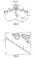
- FIG. 7 is a schematic diagram of a microfabricated CED device implanted into a brain of a patient
- FIG. 8 is a perspective view of a microfabricated CED device coupled to a standard cannula
- FIG. 9 is a schematic diagram of a microfabricated CED device implanted into a brain of a patient and an associated fluid release spatial distribution pattern
- FIG. 10 is a schematic diagram of a plurality of microfabricated CED devices positioned to surround a target site within a brain of a patient;
- FIG. 11 is an electron micrograph of another exemplary embodiment of a microfabricated CED device.
- FIG. 12 is a schematic diagram of a microfabricated CED device implanted into a spinal canal of a patient
- FIG. 13 is a schematic cross-sectional view of a microfabricated CED device implanted into an inner ear of a patient
- FIG. 14 is a schematic side view of a microfabricated CED device implanted into an inner ear of a patient
- FIG. 15 is a schematic view of microfabricated CED devices implanted into various regions of a brain
- FIG. 16 is a schematic view of a microfabricated CED device implanted into a target region during fetal surgery
- FIG. 17A is a schematic view of a microfabricated CED device having fluid delivery conduits with longitudinally staggered outlet ports;
- FIG. 17B is a schematic view of a microfabricated CED device having longitudinally staggered outlet ports and an inflatable member
- FIG. 18A is a schematic view of the device of FIG. 17B inserted into a cavernous malformation
- FIG. 18B is a schematic view of the device of FIG. 17B with the inflatable member inflated within the cavernous malformation;
- FIG. 19 is a flowchart that depicts an exemplary method of manufacturing a microfabricated CED device
- FIGS. 20A-20L are cross-sectional views of a CED device at various stages of the process of FIG. 19 ;
- FIG. 21A is a scanning electron microscope image of a microfabricated CED device
- FIG. 21B is a scanning electron microscope image of the distal tip of the CED device of FIG. 21A ;
- FIG. 22A is a schematic top view of a microfabricated CED device
- FIG. 22B is a detail schematic top view of the distal tip of the CED device of FIG. 22A ;
- FIG. 23A is a schematic view of a wafer layout that includes a plurality of microfabricated CED devices
- FIG. 23B is a schematic view of the wafer layout of FIG. 23A repeated a plurality of times on a silicon wafer;
- FIG. 23C is an image of a plurality of microfabricated CED devices produced using the layout of FIG. 23A ;
- FIG. 24A is a microscope image of a silicon substrate formed during manufacture of a CED device
- FIG. 24B is another microscope image of the substrate of FIG. 24A ;
- FIG. 24C is another microscope image of the substrate of FIG. 24A ;
- FIG. 25A is a schematic top view of a microfabricated CED device having an attached catheter portion
- FIG. 25B is a schematic end view of the device of FIG. 25A ;
- FIG. 25C is a schematic top view of the device of FIG. 25A with a nose portion and catheter body coupled thereto;
- FIG. 25D is a schematic end view of the device of FIG. 25C ;
- FIG. 26A is a top view image of an assembled CED device
- FIG. 26B is a perspective view image of the CED device of FIG. 26A ;
- FIG. 26C is a top view image of the CED device of FIG. 26A shown with a reference scale.
- the methods, systems, and devices disclosed herein generally involve convection-enhanced delivery of drugs to a target region within a patient.
- Microfluidic catheter devices are disclosed that are particularly suitable for targeted delivery of drugs via convection, including devices capable of multi-directional drug delivery and devices that control fluid pressure and velocity using the venturi effect.
- Methods of treating various diseases using such devices are also disclosed, including methods of treating cerebral and spinal cavernous malformations, cavernomas, and hemangiomas, methods of treating neurological diseases, methods of treatment using multiple microfluidic delivery devices, methods of treating hearing disorders, methods of spinal drug delivery using microfluidic devices, and methods of delivering stem cells and therapeutics during fetal surgery. Methods of manufacturing such devices are also disclosed.
- drug refers to any functional agent that can be delivered to a human or animal patient, including hormones, stem cells, gene therapies, chemicals, compounds, small and large molecules, dyes, antibodies, viruses, therapeutic agents, etc.
- microfabricated CED device microfluidic delivery device
- CED device CED device
- probe microprobe
- catheter and “microcatheter” are generally used interchangeably herein.
- FIG. 1 illustrates one exemplary embodiment of a microfabricated CED device 10 .
- the device 10 generally includes a support scaffold 12 to which one or more shank portions 14 are coupled.
- the shank portions 14 can include one of more fluid delivery conduits 16 formed thereon or therein.
- the illustrated support scaffold 12 is generally formed by an elongate body having a proximal end 18 , a distal end 20 , and a longitudinal axis 22 extending therebetween.
- a cross-section of the illustrated scaffold 12 taken in a plane normal to the longitudinal axis 22 has a substantially rectangular shape, however any of a variety of cross-sectional shapes can be used, including circular, hexagonal, and elliptical.
- the scaffold 12 can provide structural rigidity to the device 10 to facilitate insertion into target tissue.
- the distal end 20 of the support scaffold 12 can be tapered, pointed, and/or sharpened.
- the scaffold 12 is provided with a rounded atraumatic tip so as to facilitate insertion through tissue without causing trauma to the tissue.
- the support scaffold 12 can be rigid or semi-rigid and can be formed from a degradable thermoplastic polymer, for example, a degradable thermoplastic polyester or a degradable thermoplastic polycarbonate.
- the support scaffold 12 is formed from poly(lactic-co-glycolic acid) (PLGA) and is configured to biodegrade within the target tissue. This can advantageously eliminate the need to remove the support scaffold 12 once the device 10 is positioned within target tissue, thereby avoiding the potential to disrupt the positioning of the fluid delivery conduits 16 .
- PLGA poly(lactic-co-glycolic acid)
- Any of a variety of other materials can also be used to form the support scaffold 12 , including silicon or various ceramics, metals, and plastics known in the art.
- the support scaffold 12 can contain or can be impregnated with a quantity of a drug. Alternatively, or in addition, a surface of the support scaffold 12 can be coated with a drug. Exemplary drugs include anti-inflammatory components, drug permeability-increasing components, delayed-release coatings, and the like. In one embodiment, the scaffold 12 can be coated or impregnated with a corticosteroid such as dexamethasone which can prevent swelling around the injection site and disruptions to the fluid delivery pattern that can result from such swelling.
- a corticosteroid such as dexamethasone
- the scaffold 12 can have a width of approximately 100 ⁇ m to approximately 200 ⁇ m and can have a length that varies depending on the target tissue (e.g., depending on the depth at which the target tissue is situated). In one embodiment, the scaffold 12 is between 2 cm and 3 cm long.
- the scaffold 12 can also include a recess or shelf portion 24 configured to retain or mate with the shank portion 14 of the device 10 .
- the scaffold 12 can include multiple recesses or shelf portions for coupling to a plurality of shank portions 14 .
- the recesses or shelf portions can be formed on multiple different surfaces of the scaffold.
- a variety of techniques can be used to couple the shank portion 14 to the support scaffold 12 , such as surface tension from a water drop, adhesives, and/or a biocompatible petroleum jelly.
- the device 10 can also include one or more shank portions 14 that are matable to the support scaffold 12 .
- the shank portion 14 can be a flexible substrate having one or more fluid delivery conduits 16 formed therein or thereon.
- the shank portion 14 can be formed from any of a variety of materials, such as silicon or Parylene.
- One or more fluid delivery conduits 16 can be formed in or on the shank portion 14 of the device.
- the conduits 16 can extend along a surface of the shank portion 14 in a direction that is generally parallel to the longitudinal axis 22 of the scaffold 12 , and can have one or more lateral portions 26 extending in a direction that forms a non-zero angle with the longitudinal axis 22 .
- Each conduit 16 can include a fluid inlet port (not shown in FIG. 1 ) and one or more fluid outlet ports 28 .
- the fluid inlet port can be positioned at a proximal end of the device 10 , and can allow the conduit 16 to be placed in fluid communication with a fluid reservoir, e.g., via one or more pumps, meters, valves, or other suitable control devices.
- Such control devices can be used to regulate the pressure at which fluid is supplied to the device 10 , or the rate or volume of fluid that is supplied to the device 10 .
- Fluid supplied to the conduit 16 though the fluid inlet port is directed through an inner lumen of the conduit and released through the one or more fluid outlet ports 28 .
- the fluid outlet ports 28 can be sized, shaped, and/or positioned to control various release parameters of the fluid.
- the fluid outlet ports 28 can be configured to control the direction in which fluid is release from the device 10 , the distribution of the fluid within the target tissue, and the velocity or pressure at which the fluid is released.
- the shank portion 14 includes first and second parylene conduits 16 A, 16 B extending therethrough.
- the conduits 16 A, 16 B include a longitudinal portion and a plurality of lateral extensions 26 in which fluid outlet ports 28 are formed.
- the size of the fluid outlet ports 28 progressively increases towards the distal end 20 of the device 10 , which can advantageously compensate for pressure loss that occurs along the length of the device such that fluid is released from each of the plurality of fluid outlet ports 28 at substantially the same pressure.
- the illustrated fluid outlet ports 28 are also shaped to control the release direction of the fluid.
- the ports 28 A and 28 C open in a side or lateral direction, whereas the ports 28 B and 28 D open towards the top of the device 10 .
- the device can also include one or more sensors 30 mounted in or on the shank portion 14 or on the scaffold 12 .
- the sensors 30 can include temperature sensors, pH sensors, pressure sensors, oxygen sensors, tension sensors, interrogatable sensors, glutamate sensors, ion concentration sensors, carbon dioxide sensors, lactate sensors, neurotransmitter sensors, or any of a variety of other sensor types, and can provide feedback to a control circuit which can in turn regulate the delivery of fluid through the device 10 based on one or more sensed parameters.
- One or more electrodes 32 can also be provided in or on the shank portion 14 or the support scaffold 12 , which can be used to deliver electrical energy to target tissue, e.g., to stimulate the target tissue or to ablate the target tissue. In one embodiment, electrical energy is delivered through the electrodes 32 while a drug is simultaneously delivered through the fluid delivery conduits 16 .
- the device 10 can be used for CED of drugs to treat disorders of the brain, ears, other neural tissue, or other parts of a human or animal body.
- the device 10 can circumvent the blood-brain barrier (BBB) by infusing drugs under positive pressure directly into tissue.
- BBB blood-brain barrier
- the device 10 provides a number of advantages, such as 1) a smaller cross-sectional area compared with conventional needles used in CED; 2) less disturbance to tissue when inserted into the brain than conventional needles; 3) the elimination of backflow or reflux along the outside of the inserted part, which in turn, permits higher rates of drug delivery in the device 10 compared with conventional needles; 4) minimal or no occlusion of the fluid delivery conduits 16 during insertion into the brain; 5) multiple parylene conduits 16 can be fabricated into the silicon shank 14 , each conducting a distinct fluid (drug), which allows simultaneous, sequential, or programmed delivery of multiple agents; 6) the device 10 has the potential to serve simultaneously as a drug delivery system and as a sensor-equipped probe to measure local tissue characteristics such as, but not limited to, pressure, pH, ion-specific concentrations, location, and other parameters; and 7) the device 10 allows for directional control of the drug release pattern.
- the device 10 can be functionally attached to the distal end of a long, thin insertion vehicle such as a cannula or a needle in or on which a fluid attachment could be made to the fluid inlet ports of the device's fluid delivery conduits 16 .
- a long, thin insertion vehicle such as a cannula or a needle in or on which a fluid attachment could be made to the fluid inlet ports of the device's fluid delivery conduits 16 .
- This can be especially advantageous in applications involving penetration of relatively thick tissue, e.g., insertion through a human skull.
- the device 10 can also be used to deliver enzymes or other materials to modify tissue permeability and improve drug distribution in the targeted tissue.
- penetration of a drug-containing nanoparticles into brain tissue can be enhanced by enzymatic digestion of at least one brain extracellular matrix component and intracranial infusion of the nanoparticle into the brain tissue.
- at least one enzyme can be immobilized to a surface of the nanoparticle during the step of enzymatic digestion.
- the device 10 can provide the ability to deliver enzymatic and/or other materials that can, e.g., modify the drug delivery site, and therapeutic materials, in virtually any order, sequencing, and/or timing without the need to use different delivery devices and the potential complications involved in doing so.
- the device 10 can also be used to biopsy tissue, for example by passing a stylet or a grasping tool through one of the conduits 16 to a target site and then withdrawing the stylet or grasping tool from the target site with a biopsy specimen therein.
- the shank portions 14 or the support scaffold 12 can have a larger-diameter lumen extending therethrough for biopsy purposes, with smaller fluid conduits 16 formed on the exterior thereof.
- FIGS. 2A and 2B illustrate another exemplary embodiment of a microfabricated CED device 110 .
- the device 110 includes a rectangular support scaffold 112 with shank portions 114 and accompanying fluid delivery conduits 116 coupled to each of the four side surfaces thereof.
- the shank portions 114 are disposed within corresponding recesses 124 formed in the sidewalls of the support scaffold 112 .
- the shank portions 114 can be surface mounted on the scaffold 112 . Positioning of shank portions 114 and fluid delivery conduits 116 on each of the four side surfaces of the scaffold 112 can further facilitate 360 degree convective flow of drug-containing fluid from the device 110 .
- the structure and function of the device 110 is otherwise substantially the same as that of the device 10 described above, and therefore a further description thereof is omitted here for the sake of brevity.
- FIGS. 3A and 3B illustrate another exemplary embodiment of a microfabricated CED device 210 .
- the device 210 includes a cylindrical support scaffold 212 with shank portions 214 and accompanying fluid delivery conduits 216 coupled in a spaced relationship about the outer surface of the scaffold 212 .
- the shank portions 214 are disposed within corresponding recesses 224 formed in the sidewalls of the support scaffold 212 .
- the shank portions 214 can be surface mounted on the scaffold 212 .
- the flexible nature of the shank portions 214 and the fluid delivery conduits 216 permits them to be curved or otherwise contoured to match the surface profile of the scaffold 212 .
- Positioning of shank portions 214 and fluid delivery conduits 216 about the outer surface of the scaffold 212 as shown can further facilitate 360 degree convective flow of drug-containing fluid from the device.
- the structure and function of the device 210 is otherwise substantially the same as that of the device 10 described above, and therefore a further description thereof is omitted here for the sake of brevity.
- FIG. 4 is a schematic illustration of a drug delivery system 300 that includes a microcatheter CED device 310 which can be any of the devices 10 , 110 , 210 described above.
- the system 300 includes a reservoir 302 of a drug-containing fluid that is coupled to a pump 304 via a control valve 306 .
- a control valve 306 When the control valve is opened, fluid in the reservoir 302 is supplied under pressure by the pump 304 to a pressure regulator 308 , which can adjust a pressure at which the fluid is supplied to the catheter 310 .
- the control valve 306 , pump 304 , and regulator 308 can be operatively coupled to a controller 301 which can include a microprocessor and a memory and can be configured to execute a drug-delivery control program stored in a non-transitory computer-readable storage medium.
- the controller 301 can be configured to open or close the valve 306 , to turn the pump 304 on or off, to change an output pressure of the pump 304 , and/or to adjust a pressure set point of the regulator 308 .
- the controller 301 can also receive information indicative of a sensed parameter via a feedback loop that includes one or more sensors 330 mounted in or on the catheter 310 .
- the controller 301 can start or stop the flow of fluid to the catheter 310 , increase or decrease the pressure at which fluid is supplied to the catheter 310 , etc.
- the catheter 310 includes a pressure sensor 330 that measures a fluid pressure in the vicinity of the catheter 310 and the controller 301 is configured to maintain the fluid supply pressure at a substantially constant level based on feedback from the pressure sensor 330 .
- FIGS. 5A and 5B illustrate an alternative embodiment of a fluid delivery conduit that can be used with the devices described herein.
- the fluid delivery conduit 416 includes first and second upstream lumens 434 , 436 which merge into a single downstream lumen 438 .
- the inside dimension of the combined lumens 434 , 436 decreases gradually at the merge, which can advantageously increase the velocity of fluid flowing through the downstream lumen 438 .
- the cross-sectional area of the downstream lumen 438 is less than the cross-sectional area of the first upstream lumen 434 and less than the cross-sectional area of the second upstream lumen 436 , such that a flow restriction is formed in the delivery conduit 416 .
- the constricted region formed by the downstream lumen 438 has a cross-sectional area that is approximately 20% less than the cross-sectional area of a proximally-adjacent portion of the delivery conduit 416 . More preferably, the constricted region has a cross-sectional area that is approximately 30% less than the cross-sectional area of the proximally-adjacent portion of the delivery conduit. Even more preferably, the constricted region has a cross-sectional area that is approximately 40% less than the cross-sectional area of the proximally-adjacent portion of the delivery conduit.
- the proximally-adjacent portion has a height between about 1 micron and about 50 microns and the constricted region has a height between about 1 micron and about 25 microns. In another embodiment, the proximally-adjacent portion has a width between about 10 microns and about 100 microns and the constricted region has a width between about 5 microns and about 50 microns.
- a plurality of outlet ports 428 can be disposed in fluid communication with the first and second upstream lumens 434 , 436 , and/or in fluid communication with the downstream lumen 438 .
- FIG. 6 is a an electron micrograph of one exemplary embodiment of a microfabricated CED device 510 having a single fluid delivery conduit 516 mounted on a single surface of a degradable scaffold 512 .
- the fluid delivery conduit 516 is approximately 25 ⁇ m wide and the fluid outlet ports 528 are spaced approximately 500 ⁇ m apart in the lengthwise direction.
- FIG. 7 illustrates one exemplary method for convection-enhanced delivery of a drug to target tissue in a patient's brain 40 .
- a tissue opening can formed through the patient's scalp and skull 44 to expose the brain 40 .
- a pedestal 46 can optionally be mounted to the patient as shown using an epoxy or other adhesive 48 .
- the pedestal 46 can support a CED device 10 while it is inserted, and can be particularly useful in long-term implantations.
- the CED device 10 can optionally be coupled to a cannula 50 with a microfabricated interface for mating with the CED device 10 , as shown in FIG. 8 .
- a cannula 50 with a microfabricated interface for mating with the CED device 10 , as shown in FIG. 8 .
- the cannula can include a flexible catheter suitable for extended (e.g., 30 day) implantation.
- the catheter can be about 15 cm long and about 2 cm in diameter.
- the cannula can include a tubing portion that is approximately 6 feet in length with connectors for fluid and biosensor interface at the proximal end.
- the CED device 10 can be advanced through the tissue opening and into the brain 40 .
- the scaffold 12 of the CED device 10 can be rigid and can include a pointed or sharpened tip 20 to facilitate penetration through the brain tissue towards the target region.
- One or more radiopaque markers can be included in the CED device 10 to permit radiographic imaging (e.g., to confirm proper placement of the CED device 10 within or in proximity to the target tissue).
- the scaffold 12 can degrade shortly after insertion to leave behind only the flexible shank portion 14 and the fluid delivery conduits 16 mounted thereon.
- the flexible nature of the shank 14 permits the CED device 10 to move with the brain 40 if the brain 40 shifts within the skull 44 (e.g., in the direction of arrow 52 ), which prevents localized deformation of brain tissue adjacent to the CED device 10 that might otherwise occur with a rigid device. Such deformation can lead to backflow of the pressurized fluid along the surface of the device, undesirably preventing the fluid from reaching the target tissue.
- injected media e.g., a drug-containing fluid
- injected media can be supplied under positive pressure to the CED device 10 through one or more fluid inlet ports of one or more fluid delivery conduits 16 of the device 10 .
- the injected media is expelled under pressure from the fluid outlet ports of the fluid delivery conduits of the device 10 in the target region of tissue.
- the delivery profile 54 can be adjusted by varying parameters such as outlet port size, outlet port shape, delivery conduit size, delivery conduit shape, fluid supply pressure, fluid velocity, etc.
- Drug delivery can be further enhanced by strategic positioning of the CED device, and/or by using a plurality of CED devices.
- a plurality of CED probes 10 A, 10 B, 10 C, and 10 D can be positioned in a spaced relationship around a target site 56 (e.g., a tumor) such that one or more fluid outlet ports formed in each of the plurality of CED devices are aligned with the target site.
- CED devices having fluid outlet ports that are sized and positioned for directional fluid release can be oriented (e.g., with radiographic assistance) such that the direction of release is aimed towards the target tissue.
- One or more drug-containing fluids can then be delivered under positive pressure from the plurality of CED devices to the target site such that the drug substantially surrounds and saturates the target site or is delivered on several sides of the target site.
- the pressure at which fluid is supplied, or any of a variety of other delivery parameters, can be independently controlled for each of the plurality of CED devices, e.g., based on feedback from one or more microsensors disposed on the CED devices.
- a controller can be configured to increase or decrease the fluid pressure for each of the four CED devices based on feedback from pressure sensors affixed thereto, such that the release pressure of each of the four CED devices is maintained at substantially the same level.
- the plurality of CED devices can be inserted through a single tissue opening, or a plurality of separate tissue openings can be formed to facilitate insertion of the plurality of CED devices.
- CED devices having a plurality of fluid delivery conduits can advantageously be used to deliver one or more cofactors along with the drug-containing fluid.
- anti-inflammatory agents, enzymes, and various other functional agents can be delivered though a secondary conduit 16 B before, during, or after delivery of the drug-containing fluid through a primary conduit 16 A.
- Additional fluid delivery conduits can also be used for sensing or monitoring.
- the methods and devices disclosed herein can provide convection-enhanced delivery of functional agents directly to target tissue within a patient.
- This convection-enhanced delivery can be used to treat a broad spectrum of diseases, conditions, traumas, ailments, etc.
- Central-nervous-system (CNS) neoplasm for example, can be treated by delivering an antibody (e.g., an anti-epidermal growth factor (EGF) receptor monoclonal antibody) or a nucleic acid construct (e.g., ribonucleic acid interference (RNAi) agents, antisense oligonucleotide, or an adenovirus, adeno-associated viral vector, or other viral vectors) to affected tissue.
- an antibody e.g., an anti-epidermal growth factor (EGF) receptor monoclonal antibody
- a nucleic acid construct e.g., ribonucleic acid interference (RNAi) agents, antisense oligonucleotide, or an adenovirus, adeno-associated viral vector, or other viral vectors
- epilepsy can be treated by delivering an anti-convulsive agent to a target region within the brain.
- Parkinson's disease can be treated by delivering a protein such as glial cell-derived neurotrophic factor (GDNF).
- GDNF glial cell-derived neurotrophic factor
- Huntington's disease can be treated by delivering a nucleic acid construct such as a ribonucleic acid interference (RNAi) agent or an antisense oligonucleotide.
- RNAi ribonucleic acid interference
- the methods and devices disclosed herein can also be used to deliver a neurotrophin under positive pressure to treat stroke, and/or to deliver a protein such as a lysosomal enzyme to treat lysosomal storage disease.
- the disclosed methods and devices can be used to treat Alzheimer's disease by delivering anti-amyloids and/or nerve growth factor (NGF) under positive pressure.
- amyotrophic lateral sclerosis can be treated by delivering a protein such as brain-derived neurotrophic factor (BDNF) or ciliary neurotrophic factor (CNTF) under positive pressure to the brain, spinal canal, or elsewhere in the central nervous system.
- Chronic brain injury can be treated by delivering a protein such as brain-derived neurotrophic factor (BDNF) and/or fibroblast growth factor (FGF) under positive pressure in accordance with the methods and devices disclosed herein.
- BDNF brain-derived neurotrophic factor
- FGF fibroblast growth factor
- a CED device 10 can be inserted through a tissue opening formed adjacent to a vertebra 58 of a patient so as to facilitate delivery of a therapeutic agent to a target region within a spinal canal 60 of the patient.
- Traditional methods of delivering drug-containing fluid to the spinal canal result in the fluid mixing with the cerebrospinal fluid (CSF) of the patient, which carries the drug away from the target tissue and can lead to complications when the drug acts in non-target areas of the patient.
- CSF cerebrospinal fluid
- CED devices coupled with the high flow rate of drug-containing fluid, on the other hand, allows for extremely precise targeting of the drug delivery, such that delivery into the cerebrospinal fluid (CSF) of the patient can be avoided, while still allowing delivery into specific target regions of the spinal canal.
- stem cells can be delivered into the spinal canal or elsewhere in the central nervous system, for example to treat ALS.
- the methods and devices disclosed herein can also be used to treat balance or hearing disorders by injecting a drug-containing fluid directly into a portion of a patient's ear.
- Existing techniques for delivering a drug to the inner ear require entry through the outer ear 62 and the ear canal 64 , which can cause damage to the delicate structures of the ear.
- a tissue opening can instead be formed in the skull 44 behind a patient's ear 66 to allow insertion of a CED device 10 .
- the device 10 can be inserted through the tissue opening and into the target portion of the patient's ear (e.g., inner ear 68 , cochlea 70 , organ of Corti, and/or basilar membrane).
- a drug-containing fluid can then be delivered through the device 10 under positive pressure to the target ear portion.
- Any of a variety of drugs can be used to treat the ear, including human atonal gene.
- the methods and devices disclosed herein can be used to treat Alzheimer's Disease or other neurological conditions by delivering a drug-containing fluid to the cerebral cortex.
- the drug-containing fluid can be delivered to any of a variety of regions of the brain, either individually or together and either simultaneously or sequentially. These regions can include the auditory cortex, the inferotemporal cortex, the prefrontal cortex, the premotor cortex, the primary motor cortex, the supplementary motor cortex, the somatosensory cortex, the parietal cortex, the visual cortex, the gustatory cortex, etc.
- the methods and devices disclosed herein can also be used to deliver therapeutics (such as stem cells) to a fetus or to a patient in which the fetus is disposed. This can be particularly advantageous in delivering therapeutics during fetal surgery.
- a micro-fluidic CED device can be used to deliver a drug-containing fluid to an umbilical cord, an umbilical artery, an umbilical vein, a placenta, and/or a uterine wall.
- FIG. 17A illustrates another exemplary embodiment of a microfluidic CED device 610 that includes a support scaffold 612 , at least one shank 614 , and at least first and second fluid delivery conduits 616 A, 616 B.
- the fluid delivery conduits 616 A, 616 B have differing lengths, such that the outlet ports 628 A, 628 B of the fluid delivery conduits are staggered longitudinally along the shank 614 .
- the first and second fluid delivery conduits 616 A, 616 B terminate at a distance D apart from one another such that the outlet ports 628 A, 628 B thereof are staggered in the longitudinal direction.
- the distance D is between about 0.02 ⁇ m and about 100 mm, and preferably between about 0.1 ⁇ m and about 10 mm.
- the device 610 can also include one or more sensors 630 and/or electrodes 632 , as described above.
- the structure and function of the device 610 is otherwise substantially the same as that of the device 10 described above, and therefore a further description thereof is omitted here for the sake of brevity.
- the device 610 can be inserted into a target region (e.g., a cavernous malformation with a patient's central nervous system) such that the outlet port 628 B of the second fluid delivery conduit 616 B is disposed within a central portion of the target region (e.g., the core of the cavernous malformation) and such that the outlet port 628 A of the first fluid delivery conduit 616 A is disposed within a peripheral portion of the target region (e.g., the exterior surface of the cavernous malformation).
- the target region can be treated both from the inside-out and from the outside-in.
- the device 610 can allow a drug to be delivered into the core of the cavernous malformation as well as to the surface of the cavernous malformation where the vascular-type cells are proliferating.
- FIG. 17B illustrates another exemplary embodiment of a microfluidic CED device 710 .
- the device 710 is substantially identical to the device 610 of FIG. 17A , except that an inflatable member 772 (e.g., a reinforced and/or conformable balloon) is included in the device 710 .
- the inflatable member 772 can be in fluid communication with the first fluid delivery conduit 716 A, such that fluid can be supplied through the first fluid delivery conduit 716 A to inflate the inflatable member 772 and increase the volume of the inflatable member 772 or increase the pressure within the inflatable member 772 .
- fluid can be withdrawn from the inflatable member 772 via the first fluid delivery conduit 716 A to reduce the volume of the inflatable member 772 or reduce the pressure therein.
- the inflatable member 772 can be coupled to an exterior of the device 710 (e.g., such that it substantially surrounds a portion of the device 710 ), or can be configured to deploy from within a recess formed in the device 710 .
- the structure and function of the device 710 is otherwise substantially the same as that of the device 10 described above, and therefore a further description thereof is omitted here for the sake of brevity.
- the methods and devices disclosed herein can be used to treat a cavernous malformation, for example by delivering one or more drugs thereto.
- a CED device such as the device 710 described above can be inserted into a cavernous malformation 74 such that the outlet port 728 A of the first fluid delivery conduit 716 A and the outlet port 728 B of the second fluid delivery conduit 716 B are both disposed within the cavernous malformation 74 .
- Fluid containing a drug, such as one or more antiangiogenesis factors can then be supplied to the interior of the cavernous malformation 74 through the second fluid delivery conduit 716 B.
- fluid can be supplied through the first fluid delivery conduit 716 A to inflate the inflatable member 772 and/or increase the pressure within the inflatable member 772 , as shown in FIG. 18B .
- the inflatable member 772 inflates within the cavernous malformation 74 , and/or as the pressure increases within the inflatable member 772 , a compressive force is exerted on the drug-containing fluid previously released into the cavernous malformation 74 , pressing the fluid into the surrounding tissue.
- microfluidic CED devices disclosed herein can be manufactured using any of a variety of techniques.
- the devices can be manufactured by micro-fabricating a silicon substrate, and then coupling the finished piece to a catheter portion that includes one or more micro-capillaries.
- a lithographic microfabrication process can be used to manufacture a CED device.
- the process can include (1) back etching a silicon substrate to form shank and tailpiece depths, (2) spin coating polyimide on the top side of the silicon substrate, (3) spin coating sacrificial resist to define the micro-channels, (4) applying a parylene coat to the top side of the polyimide layer, (5) applying an aluminum mask for removing the sacrificial resist and thereby forming parylene channels, and (6) front etching the silicon substrate to form device bodies.
- the process can include (1) front etching a silicon substrate to form device bodies, (2) spray coating polyimide on both sides of the silicon substrate without masking, (3) spray coating a sacrificial resist on the polyimide, (4) applying a parylene coat to the top side, and (5) applying an aluminum mask for removing the sacrificial resist and thereby forming parylene channels.
- FIG. 19 illustrates an exemplary microfabrication process for manufacturing a CED device. While various methods or processes disclosed herein may be shown in relation to a flowchart or flowcharts, it should be noted that any ordering of method steps implied by such flowcharts or the description thereof is not to be construed as limiting the method to performing the steps in that order. Rather, the various steps of each of the methods disclosed herein can be performed in any of a variety of sequences. In addition, as the illustrated flowchart(s) are merely exemplary embodiments, various other methods that include additional steps or include fewer steps than illustrated are also within the scope of the present invention.
- a cleaning process can be performed on a silicon wafer from which the CED device will be fabricated.
- a hot nanostrip clean can be performed for 30 minutes at 50 degrees C., followed by a deionized (“DI”) water rinse and spin rinse drying (“SRD”), e.g., using a VERTEQ spin rinse dryer.
- DI deionized
- SRD spin rinse drying
- an RCA clean is performed for 15 minutes at 70 degrees C. using NH4OH:H2O, followed by 15 minutes at 70 degrees C. using HCL:H2O, followed by a DI water rinse and SRD.
- the wafer can undergo a dehydration bake.
- the wafer can be baked at 180 degrees C. for 5 minutes using a contact hotplate.
- the dehydration bake can be omitted in some cases, as the wafer can be heated to 400 degrees C. during the plasma-enhanced chemical vapor deposition (“PECVD”) step discussed below. Accordingly, the step time in the PECVD process can be increased to accommodate extra dehydration time. Omitting hotplate dehydration can also reduce contamination left behind by prior uses of the hotplate.
- PECVD plasma-enhanced chemical vapor deposition
- an oxide hard mark can be deposited on the silicon wafer.
- the hard mark can be deposited by PECVD Oxide Deposition (2.5 ⁇ m, N1.46 Oxide Recipe), and the thickness can be confirmed using a measuring system, such as those manufactured by FILMETRICS.
- step S 806 the oxide hard mask 902 can be patterned on the silicon wafer 900 , for example as shown in FIG. 20A .
- An exemplary patterning process includes:
- Vapor prime (this can be performed in an oven, such as those manufactured by YIELD ENGINEERING SYSTEMS (“YES”) and can be important for the wet etch process)
- Descum using an etcher such as an OXFORD 80 etcher (Oxygen Plasma Clean, 150 wattsRF, 50 sccms O2, 60 mTorr, 15 sec)
- OXFORD 80 etcher Oxygen Plasma Clean, 150 wattsRF, 50 sccms O2, 60 mTorr, 15 sec
- Oxide Etch OXFORD 80#2 (CHF3O2 Oxide Etch, 240 watts, 100 min ( ⁇ 5 twenty min cycles), 50 sccms CHF3, 2 sccms O2, 40 mTorr, 10 degC, DC Bias 119 volts)
- OXFORD 80 Oxygen Plasma Clean, 150 wattsRF, 50 sccms O2, 60 mTorr, 10 min
- Strip Resist Hot Strip Bath (15 min 70 deg NMP/TMAH/PG), DI Rinse and SRD
- Strip Resist Acetone Bath, isopropyl alcohol (“IPA”) Bath, DI Water Bath with DI Rinse and SRD
- Strip Resist e.g., using a hot piranha cleaning system manufactured by HAMATECH
- a CHF3O2 reactive ion “dry” etch instead of using wet BOE to pattern the oxide, a CHF3O2 reactive ion “dry” etch can be used.
- BOE a CHF3O2 reactive ion “dry” etch
- One advantage of using BOE is that it can be relatively inexpensive (no tool charges and many wafers can be etched at the same time) and a thinner resist can be used (such as S 1813 ).
- One disadvantage is that the dimensions can extend out by 3 ⁇ m all around. This can be less of a concern when the critical feature sizes are really large.
- Another potential problem is that BOE can sometimes capillary underneath the resist layer (hence the need for good adhesion) and etch in regions where etching is not intended.
- RIE reactive ion etch
- the resist can be left in place during the initial etching steps in the subsequent Bosch DRIE.
- Resist stripping can be done with a first O2 plasma clean followed by a wet chemical stripper followed by a DI rinse and dry N2 blow dry.
- step S 808 the silicon can undergo deep reactive ion etching (“DRIE”) to remove silicon from the wafer 900 in the pattern defined by the oxide hard mask 902 , for example as shown in FIG. 20B .
- DRIE deep reactive ion etching
- the edge bead is removed (if the resist was not removed previously).
- an etching system such as those manufactured by UNAXIS can be used to etch through the wafer, leaving 100 ⁇ m remaining on the frontside.
- the etch can be performed using the following parameters:
- Wafer Etch ⁇ 800 Loops O-Trench (400 ⁇ m into 500 ⁇ m Wafer)
- an OERLIKON etching can be performed instead.
- Thinner wafers e.g., about 300 ⁇ m thick as opposed to about 500 ⁇ m thick
- the etching process can be followed by:
- OXFORD 80 Oxygen Plasma Clean, 150 wattsRF, 50 sccms O2, 60 mTorr, 10 min
- Strip Resist Hot Strip Bath (15 min 70 deg NMP/TMAH/PG), DI Rinse and SRD
- a PECVD oxide etch stop can be performed on the backside of the wafer, for example as shown in FIG. 20C .
- the PECVD oxide 904 can be deposited down at the very bottom of the trenches formed in step S 808 , e.g., using PECVD oxide deposition of 1.0 ⁇ m on the backside of the wafer with frontside etch stop.
- a silicon on insulator (“SOI”) wafer can be used, in which case the buried oxide (“BOX”) layer on the SOI wafer can act as the etch stop making the PECVD stop layer and DRIE from the backside unnecessary.
- Vapor hydrogen fluoride (“HF”) can be used in such embodiments to release the final device from the BOX.
- a polyimide layer 906 can be patterned on the frontside of the wafer 900 , for example as shown in FIG. 20D .
- the following process is used to pattern the polyimide layer:
- OXFORD 80 Oxygen Plasma Clean, 150 wattsRF, 50 sccms O2, 60 mTorr, 15 sec
- the microfluidic channels can be defined using sacrificial resist 908 , for example as shown in FIG. 20E .
- the following process is used to define the microfluidic channels:
- MA6 Soft Contact
- MASK3 CHANNEL (Frontside)
- OXFORD 80 Oxygen Plasma Clean, 150 wattsRF, 50 sccms O2, 60 mTorr, 60 sec
- the thickness of the resist layer 908 can determine the height of the microfluidic channel.
- the width of the resist layer 908 (after exposure and development) determines the width of the microfluidic channel. To avoid cracking of the resist 908 , this step can be done with a slow ramp up and ramp down.
- Reflow of the resist is not always necessary, however, as the wafer can also be coated using conformal evaporation or sputter deposition with both of these processes allowing many more wafers to be coated at the same time as compared to the non-conformal evaporators.
- a layer of parylene 910 is deposited over the polyimide layer 906 and the sacrificial resist 908 , for example as shown in FIG. 20F .
- the parylene layer 910 can have a thickness of approximately 5 ⁇ m. The following process can be used for the parylene deposition:
- OXFORD 80 150 wattsRF, 50 sccms O2, 60 mTorr, 30 sec
- Parylene can be a highly conformal layer and some material can therefore be coated on the backside of each wafer. Parylene deposition can be performed on, e.g., three wafers at one time. A typical parylene deposition process can take approximately 6 hours.
- step S 818 aluminum hard mask evaporation can be performed to apply an aluminum layer 912 over the parylene layer 910 , as shown in FIG. 200 .
- the following process can be used for the aluminum hard mask evaporation:
- OXFORD 80 150 wattsRF, 50 sccms O2, 60 mTorr, 30 sec
- Evaporate or sputter aluminum: conformal: 150 nm (2 A/sec)
- step S 820 the aluminum hard mask 912 can be patterned, for example as shown in FIG. 20H .
- the following process can be used to pattern the aluminum hard mask:
- Softbake3 115 degrees C., or,
- MASK4 ALUMINUM (Frontside)
- wet aluminum Etch (5 min)—the wet aluminum etch can undercut the resist etch mask 914 so the CAD layout can be adjusted accordingly to accommodate for this.
- OXFORD 80 Oxygen Plasma Clean, 150 wattsRF, 50 sccms O2, 60 mTorr, 10 min
- Strip Resist Hot Strip Bath (15 min 70 deg NMP/TMAH/PG), DI Rinse and SRD
- Strip Resist Acetone Bath, IPA Bath, DI Water Bath with DI Rinse and SRD
- step S 820 Upon completion of step S 820 , a strip of aluminum 912 has been deposited overtop of the parylene layer 910 to act as a hard etch mask as per FIG. 20H .
- step S 822 etch removal of peripheral parylene can be performed.
- the parylene layer 910 is removed from peripheral regions 916 of the wafer 900 .
- the following process can be used to remove the parylene etch:
- Parylene Etch OXFORD 80 (Frontside, Oxygen Plasma Clean, 150 wattsRF, 20-25 min, Complete Removal of 5 ⁇ m Parylene Layer)
- Parylene Etch OXFORD 80 (Backside, Oxygen Plasma Clean, 150 wattsRF, 10-15 min with Chips)
- FIG. 20I illustrates the system after parylene etch removal.
- the parylene has been etched all the way down to the silicon surface in the peripheral regions and 100 ⁇ m of silicon around the periphery of each device is holding the device affixed to the wafer.
- the resist layer can be made thick enough to accommodate 5 ⁇ m of parylene etching and 100 ⁇ m of silicon etching. Otherwise, a new resist layer can be applied.
- step S 824 the device outline can be defined, for example as shown in FIG. 20J .
- the following process can be used to define the device outline:
- OXFORD 80 Oxygen Plasma Clean, 150 wattsRF, 50 sccms O2, 60 mTorr, 2 min
- step S 826 holes can be opened in the parylene channel(s).
- the aluminum 912 can be used as a hard mask to open up access holes into the parylene channel. Over-etching can be preferred here to make sure that the parylene 910 has been cleared and the sacrificial resist 908 is accessible. Prior to this step, there is no access by any solvents to the sacrificial resist 908 inside the channel. The following process can be used to open holes in the parylene channel:
- Parylene Etch OXFORD 80: Oxygen Plasma Clean: 150 wattsRF, 50 sccms O2, 60 mTorr, 20-25 min Etch)
- a wet aluminum etch can be performed to remove the etch mask, for example using the following process:
- a wet BOE etch can be performed to remove the PECVD oxide stop layer 904 , for example using the following process:
- each device is held in place only by the device “tabs” or “bridges” in the 1 ⁇ m silicon layer.
- step S 832 the sacrificial resist 908 can be cleared, for example as shown in FIG. 20L .
- the following process can be used to clear the sacrificial resist:
- the wafers are not allowed to dry in-between these bathing steps, which can prevent resist residue from crystallizing at the inlet/outlet ports.
- the device cross section is as shown in FIG. 20L .
- the sacrificial resist is removed before the individual devices are harvested (i.e., broken-out) from the wafer, making the resist removal process less cumbersome and time-consuming.
- the devices can be harvested from the wafer. This can be performed, e.g., by using tweezers to push on the body of each device until the tabs break and the device falls from the wafer onto a clean wipe. Once separated from the wafer, the device can be picked up from the clean wipe and placed into a tacky GelBox, preferably with the access ports facing up.
- the devices can be assembled with PEEK tubing to form a finished CED device.
- the contact surface of the PEEK tubing can be treated using O2 plasma and mechanical roughening for good adhesion, and then attached to the device using an adhesive such as Epoxy 907 manufactured by MILLER-STEPHENSON.
- the finished devices can have an 1850 ⁇ m catheter tip length, a 1750 ⁇ m square body, a 1750 ⁇ m shoulder length, and a nominal catheter tip width of 25 ⁇ m. Leaving allowance for test areas around the periphery, 100 or more of such devices can be fabricated from a single 4-inch wafer.
- FIG. 21B illustrates a scanning electron microscope (SEM) image of the tip 922 of a completed CED device 924 .
- SEM scanning electron microscope
- the microfabricated portion 1002 of a multi-lumen CED device 1000 is illustrated schematically in FIG. 22A .
- the microfabricated portion 1002 includes a body portion 1004 with a shank or tip 1006 extending distally therefrom and first and second legs 1008 , 1010 extending proximally therefrom.
- the body portion can have a length of approximately 1.5 mm.
- First and second parylene channels 1012 , 1014 are formed on the silicon substrate. The first parylene channel 1012 extends along the first leg 1008 , across the body portion 1004 , and along the tip 1006 .
- the second parylene channel 1014 extends along the second leg 1010 , across the body portion 1004 , and along the tip 1006 .
- the parylene channels 1012 , 1014 can include 90 degree turns at their distal end, such that the outlet ports 1016 , 1018 of the channels are aimed in a direction perpendicular to the longitudinal axis of the tip 1006 .
- FIG. 23A illustrates a layout of eight microfabricated portions 1002 having various lengths. As shown in FIG. 23B , the layout of FIG. 23A can be repeated across the available surface area of a silicon wafer. FIG. 23C illustrates a set of eight microfabricated portions 1002 after having been harvested from the wafer.
- FIGS. 24A-24C illustrate SEM images of the microfabricated portions 1002 of the device 1000 , before creation of the parylene channels 1012 , 1014 .
- the multi-lumen CED device 1000 also includes a proximal catheter portion 1020 which can be assembled with the microfabricated portion 1002 .
- the catheter portion 1020 can include a quartz double-bore body 1022 with first and second PEEK micro-capillaries 1024 , 1026 extending therethrough.
- the catheter portion 1020 can be mated to the microfabricated portion 1002 by inserting the first and second legs 1008 , 1010 into the body 1022 , such that the first and second micro-capillaries 1024 , 1026 are in fluid communication with the first and second parylene channels 1012 , 1014 .
- An adhesive can be used as described above to couple the two portions 1002 , 1020 of the device 1000 to one another and to form a fluid-tight seal.
- FIG. 25B A proximal end-view of the device 1000 at this stage of assembly is shown in FIG. 25B .
- the silicon body portion 1004 extending from the catheter portion 1020 has a flat, generally rectangular shape, which if left exposed can make tissue penetration with the device 1000 difficult.
- a nose portion 1028 can be coupled to the device 1000 to encapsulate the flat wafer body 1004 .
- the nose portion 1028 can have any of a variety of shapes, including conical, cylindrical, hemispherical, and so forth, and can be sharp or blunt.
- the gradual taper provided by the nose portion 1028 can facilitate insertion of the device 1000 into tissue and can also form a better seal with surrounding tissue, thereby reducing the possibility for fluid delivered under pressure through the device 1000 to migrate back along the exterior surface of the device away from the target treatment area.
- the nose portion 1028 has a maximum outside diameter of between about 1 mm and about 1.5 mm.
- the nose portion 1028 can be formed using epoxy or it can be a separate micro-machined part that is assembled onto the microfabricated portion 1002 . As also shown in FIG.
- a catheter/cannula body 1030 can extend over the catheter portion 1020 of the device 1000 to encapsulate the proximal end of the microfabricated portion 1002 and the micro-capillaries 1024 , 1026 .
- a proximal end view of the device 1000 at this stage of assembly is shown in FIG. 25D .
- Images of an exemplary assembled device are shown in FIGS. 26A-26C .
- the device 1000 can be configured to deliver fluid at a flow rate between about 5 ⁇ L per minute and about 10 ⁇ L per minute.
- the channels 1012 , 1014 can each have a height of approximately 10 microns and a width of approximately 20 microns in the case of a rectangular channel, or can each have a diameter of about 20 microns in the case of a round channel.
- any of the various treatments described herein can further include delivering a cofactor to the target tissue, such as a corticosteroid impregnated in the scaffold of the device, a corticosteroid coated onto the scaffold, and/or a propagation enhancing enzyme.
- a cofactor such as a corticosteroid impregnated in the scaffold of the device, a corticosteroid coated onto the scaffold, and/or a propagation enhancing enzyme.
- any of the various treatments described herein can further include long-term implantation of the device (e.g., for several hours or days) to facilitate long-term treatments and therapies.
Landscapes
- Health & Medical Sciences (AREA)
- Life Sciences & Earth Sciences (AREA)
- Hematology (AREA)
- Public Health (AREA)
- Engineering & Computer Science (AREA)
- Anesthesiology (AREA)
- Biomedical Technology (AREA)
- Heart & Thoracic Surgery (AREA)
- Veterinary Medicine (AREA)
- Animal Behavior & Ethology (AREA)
- General Health & Medical Sciences (AREA)
- Pulmonology (AREA)
- Biophysics (AREA)
- Vascular Medicine (AREA)
- Medicines That Contain Protein Lipid Enzymes And Other Medicines (AREA)
- Pharmaceuticals Containing Other Organic And Inorganic Compounds (AREA)
- Medicines Containing Material From Animals Or Micro-Organisms (AREA)
- Infusion, Injection, And Reservoir Apparatuses (AREA)
- Materials For Medical Uses (AREA)
Priority Applications (2)
| Application Number | Priority Date | Filing Date | Title |
|---|---|---|---|
| US13/563,786 US10137244B2 (en) | 2011-08-01 | 2012-08-01 | Microfluidic drug delivery devices with venturi effect |
| US16/188,402 US20190117886A1 (en) | 2011-08-01 | 2018-11-13 | Microfluidic drug delivery devices with venturi effect |
Applications Claiming Priority (9)
| Application Number | Priority Date | Filing Date | Title |
|---|---|---|---|
| US201161513961P | 2011-08-01 | 2011-08-01 | |
| US201161513948P | 2011-08-01 | 2011-08-01 | |
| US201161513935P | 2011-08-01 | 2011-08-01 | |
| US201161513954P | 2011-08-01 | 2011-08-01 | |
| US201161513943P | 2011-08-01 | 2011-08-01 | |
| US201161513939P | 2011-08-01 | 2011-08-01 | |
| US201161513952P | 2011-08-01 | 2011-08-01 | |
| US201261615939P | 2012-03-27 | 2012-03-27 | |
| US13/563,786 US10137244B2 (en) | 2011-08-01 | 2012-08-01 | Microfluidic drug delivery devices with venturi effect |
Related Child Applications (1)
| Application Number | Title | Priority Date | Filing Date |
|---|---|---|---|
| US16/188,402 Division US20190117886A1 (en) | 2011-08-01 | 2018-11-13 | Microfluidic drug delivery devices with venturi effect |
Publications (2)
| Publication Number | Publication Date |
|---|---|
| US20130035574A1 US20130035574A1 (en) | 2013-02-07 |
| US10137244B2 true US10137244B2 (en) | 2018-11-27 |
Family
ID=47627379
Family Applications (4)
| Application Number | Title | Priority Date | Filing Date |
|---|---|---|---|
| US13/563,786 Active 2033-02-13 US10137244B2 (en) | 2011-08-01 | 2012-08-01 | Microfluidic drug delivery devices with venturi effect |
| US13/563,787 Abandoned US20130035660A1 (en) | 2011-08-01 | 2012-08-01 | Multidirectional microfluidic drug delivery devices with conformable balloons |
| US13/563,785 Active 2033-04-15 US10434251B2 (en) | 2011-08-01 | 2012-08-01 | Multi-directional microfluidic drug delivery device |
| US16/188,402 Abandoned US20190117886A1 (en) | 2011-08-01 | 2018-11-13 | Microfluidic drug delivery devices with venturi effect |
Family Applications After (3)
| Application Number | Title | Priority Date | Filing Date |
|---|---|---|---|
| US13/563,787 Abandoned US20130035660A1 (en) | 2011-08-01 | 2012-08-01 | Multidirectional microfluidic drug delivery devices with conformable balloons |
| US13/563,785 Active 2033-04-15 US10434251B2 (en) | 2011-08-01 | 2012-08-01 | Multi-directional microfluidic drug delivery device |
| US16/188,402 Abandoned US20190117886A1 (en) | 2011-08-01 | 2018-11-13 | Microfluidic drug delivery devices with venturi effect |
Country Status (9)
| Country | Link |
|---|---|
| US (4) | US10137244B2 (enExample) |
| EP (2) | EP2739341B1 (enExample) |
| JP (1) | JP6230996B2 (enExample) |
| KR (1) | KR102059383B1 (enExample) |
| CN (1) | CN103826690B (enExample) |
| AU (4) | AU2012290129B2 (enExample) |
| CA (3) | CA3125150A1 (enExample) |
| ES (1) | ES2854832T3 (enExample) |
| WO (1) | WO2013019830A2 (enExample) |
Cited By (3)
| Publication number | Priority date | Publication date | Assignee | Title |
|---|---|---|---|---|
| US10806396B2 (en) | 2015-01-26 | 2020-10-20 | Alcyone Lifesciences, Inc. | Drug delivery methods with tracer |
| US11213653B2 (en) | 2012-12-18 | 2022-01-04 | Alcyone Lifesciences, Inc. | Systems and methods for reducing or preventing backflow in a delivery system |
| WO2023091939A1 (en) * | 2021-11-16 | 2023-05-25 | Massachusetts Institute Of Technology | Multifunctional microelectronics fibers as implantable bioelectronic interfaces |
Families Citing this family (53)
| Publication number | Priority date | Publication date | Assignee | Title |
|---|---|---|---|---|
| CA3125150A1 (en) | 2011-08-01 | 2013-02-07 | Alcyone Lifesciences, Inc. | Microfluidic drug delivery devices |
| WO2014204954A1 (en) | 2013-06-17 | 2014-12-24 | Alcyone Lifesciences, Inc. | Methods and devices for protecting catheter tips and stereotactic fixtures for microcatheters |
| ES2738298T3 (es) * | 2013-07-31 | 2020-01-21 | Alcyone Lifesciences Inc | Sistemas y métodos de suministro de fármacos, tratamiento y monitoreo |
| KR101562865B1 (ko) * | 2014-01-24 | 2015-10-26 | 한국과학기술연구원 | 신경 영양인자를 감지하기 위한 초소형 센서 시스템 |
| US10213564B2 (en) | 2014-05-19 | 2019-02-26 | Frank J. Cain | Biomedical aural delivery systems and methods |
| WO2016014464A1 (en) | 2014-07-21 | 2016-01-28 | The Cleveland Clinic Foundation | Convection enhanced delivery device and system |
| US9968765B2 (en) | 2014-07-21 | 2018-05-15 | The Cleveland Clinic Foundation | Convection enhanced delivery device and system |
| MX2017009336A (es) | 2015-01-16 | 2017-11-15 | Voyager Therapeutics Inc | Polinucleótidos dirigidos al sistema nervioso central. |
| US10130740B2 (en) * | 2015-03-17 | 2018-11-20 | Wells Johnson Company | Pressure control during processing of adipose tissue |
| US10143811B2 (en) * | 2015-03-17 | 2018-12-04 | Wells Johnson Company | Fluid management of adipose tissue |
| WO2016183123A1 (en) | 2015-05-11 | 2016-11-17 | Alcyone Lifesciences, Inc. | Drug delivery systems and methods |
| US10286128B2 (en) * | 2015-05-22 | 2019-05-14 | Wells Johnson Company | Pressure control during processing of adipose tissue |
| KR102483951B1 (ko) | 2015-06-22 | 2023-01-03 | 삼성디스플레이 주식회사 | 액정 표시 장치 및 액정 표시 장치의 제조 방법 |
| US10315016B2 (en) * | 2016-01-04 | 2019-06-11 | Corflow Therapeutics Ag | System and methods for treating MVO |
| JP2019502473A (ja) | 2016-01-04 | 2019-01-31 | アルキオーネ・ライフサイエンシズ・インコーポレイテッドAlcyone Lifesciences, Inc. | 脳卒中を治療するための方法および装置 |
| JP6729026B2 (ja) * | 2016-06-15 | 2020-07-22 | ウシオ電機株式会社 | マイクロ流路チップおよび検体濃度測定装置 |
| US10406336B2 (en) | 2016-08-03 | 2019-09-10 | Neil S. Davey | Adjustable rate drug delivery implantable device |
| CN114887153A (zh) | 2016-12-21 | 2022-08-12 | 亚克安娜治疗学有限公司 | 药物递送系统和方法 |
| KR20190098215A (ko) | 2016-12-21 | 2019-08-21 | 멤젠 엘엘씨 | 무장된 복제-가능 종양 분해 아데노바이러스 |
| WO2018169955A1 (en) * | 2017-03-14 | 2018-09-20 | Massachusetts Institute Of Technology | Systems and methods for neural drug delivery and modulation of brain activity |
| EP3662060A2 (en) | 2017-08-03 | 2020-06-10 | Voyager Therapeutics, Inc. | Compositions and methods for delivery of aav |
| CA3076035A1 (en) | 2017-09-19 | 2019-03-28 | Corflow Therapeutics Ag | Intracoronary characterization of microvascular obstruction (mvo) and myocardial infarction |
| US10675438B2 (en) * | 2017-11-15 | 2020-06-09 | Alcyone Lifesciences, Inc. | Therapy specific, pre-programmed auto injection device |
| EP3761892B1 (en) | 2018-03-09 | 2024-07-24 | Corflow Therapeutics AG | System for diagnosing and treating microvascular obstructions |
| US20190314574A1 (en) | 2018-04-13 | 2019-10-17 | Alcyone Lifesciences, Inc. | Devices and methods for percutaneous lung intratumoral therapy delivery |
| TW202015742A (zh) | 2018-05-15 | 2020-05-01 | 美商航海家醫療公司 | 投遞腺相關病毒(aav)之組成物和方法 |
| MX2020012077A (es) | 2018-05-15 | 2021-03-09 | Voyager Therapeutics Inc | Composiciones y metodos para el tratamiento de la enfermedad de parkinson. |
| WO2019222444A2 (en) | 2018-05-16 | 2019-11-21 | Voyager Therapeutics, Inc. | Directed evolution |
| EP3793686A1 (en) | 2018-05-16 | 2021-03-24 | Voyager Therapeutics, Inc. | Aav serotypes for brain specific payload delivery |
| US12100516B2 (en) | 2018-05-31 | 2024-09-24 | Corflow Therapeutics Ag | Microfluidic coronary circulatory model |
| WO2020023612A1 (en) | 2018-07-24 | 2020-01-30 | Voyager Therapeutics, Inc. | Systems and methods for producing gene therapy formulations |
| US10940290B2 (en) * | 2018-08-27 | 2021-03-09 | Alcyone Lifesciences, Inc. | Fluid delivery systems and methods |
| AU2019327386A1 (en) * | 2018-08-27 | 2021-03-18 | Alcyone Therapeutics, Inc. | Fluid delivery systems and methods |
| AU2019333136B2 (en) * | 2018-08-29 | 2022-11-17 | W. L. Gore & Associates, Inc. | Drug therapy delivery systems and methods |
| US20200078509A1 (en) * | 2018-09-12 | 2020-03-12 | Xinova, LLC | Micro-dispenser based ear treatment |
| EP3852653B1 (en) | 2018-09-21 | 2023-11-08 | CorFlow Therapeutics AG | Apparatus for assessment of microvascular dysfunction |
| WO2020077165A1 (en) | 2018-10-12 | 2020-04-16 | Voyager Therapeutics, Inc. | Compositions and methods for delivery of aav |
| US11857326B2 (en) * | 2019-03-08 | 2024-01-02 | Neuroone Medical Technologies Corporation | Agent-delivering neural probe devices and related systems and methods |
| US20200305742A1 (en) * | 2019-03-27 | 2020-10-01 | Kamran Ghodsian | System and method for child-birth monitoring and assistance |
| US12172037B2 (en) * | 2019-08-15 | 2024-12-24 | The Board Of Trustees Of The Leland Stanford Junior University | Systems and methods for mechanogenetic functional ultrasound imaging |
| WO2021035190A1 (en) | 2019-08-21 | 2021-02-25 | Corflow Therapeutics Ag | Controlled-flow infusion catheter and method |
| WO2021046155A1 (en) | 2019-09-03 | 2021-03-11 | Voyager Therapeutics, Inc. | Vectorized editing of nucleic acids to correct overt mutations |
| WO2021176672A1 (ja) * | 2020-03-05 | 2021-09-10 | 日本ライフライン株式会社 | デリバリシャフトおよびデリバリシステム |
| US12435407B2 (en) | 2020-08-03 | 2025-10-07 | Neuroone Medical Technologies Corporation | Methods for making probe devices and related devices |
| US11744939B2 (en) | 2020-10-29 | 2023-09-05 | Medtronic, Inc. | Cyclic intrathecal drug delivery system and biomarker monitoring |
| JPWO2022181126A1 (enExample) * | 2021-02-26 | 2022-09-01 | ||
| WO2022241099A2 (en) * | 2021-05-12 | 2022-11-17 | Arizona Board Of Regents On Behalf Of The University Of Arizona | In situ soil gas probes and sampling sytems |
| ES3031889T3 (en) * | 2021-08-18 | 2025-07-11 | Dixi Neurolab Inc | Injectrode with multiple electrical sensors |
| CN115869492A (zh) * | 2022-05-26 | 2023-03-31 | 杭州堃博生物科技有限公司 | 介入系统、控制方法、计算机设备、程序产品以及存储介质 |
| CN116999412A (zh) * | 2023-08-03 | 2023-11-07 | 四川迈可隆生物科技有限公司 | 一种含有倍他米松药物的缓释微球制剂及其制备方法 |
| WO2025184653A1 (en) * | 2024-03-01 | 2025-09-04 | Massachusetts Institute Of Technology | Micro-invasive neural system for delivering therapeutic agents for the treatment of neurological disorders |
| CN117982146B (zh) * | 2024-04-07 | 2024-07-12 | 华中科技大学 | 用于颅内肿瘤切除手术监测与治疗的水凝胶混合电子系统 |
| CN119385986A (zh) * | 2024-09-19 | 2025-02-07 | 江苏知原药业股份有限公司 | 一种特比萘芬成膜组合物的文丘里效应制备方法 |
Citations (182)
| Publication number | Priority date | Publication date | Assignee | Title |
|---|---|---|---|---|
| US3460537A (en) | 1966-09-26 | 1969-08-12 | Donald C Zeis | Stereotactic guide for use in the creation of destructive brain lesions |
| US3886948A (en) | 1972-08-14 | 1975-06-03 | Hakim Co Ltd | Ventricular shunt having a variable pressure valve |
| US4146029A (en) | 1974-04-23 | 1979-03-27 | Ellinwood Jr Everett H | Self-powered implanted programmable medication system and method |
| US4692146A (en) | 1985-10-24 | 1987-09-08 | Cormed, Inc. | Multiple vascular access port |
| US4885945A (en) | 1988-02-23 | 1989-12-12 | Activational Systems, Inc. | Micropipettes and fabrication thereof |
| US4917686A (en) | 1985-12-16 | 1990-04-17 | Colorado Biomedical, Inc. | Antimicrobial device and method |
| US4979284A (en) | 1987-12-05 | 1990-12-25 | Renishaw Plc | Apparatus for changing a sensing device |
| US5088208A (en) | 1988-10-11 | 1992-02-18 | Renishaw Plc | Measurement probe for position determining apparatus |
| US5190046A (en) | 1992-05-01 | 1993-03-02 | Shturman Cardiology Systems, Inc. | Ultrasound imaging balloon catheter |
| WO1995005864A1 (en) | 1993-08-27 | 1995-03-02 | Government Of The United States Of America, Represented By The Secretary Of The Department Of Health And Human Services | Convection-enhanced drug delivery |
| US5407431A (en) | 1989-07-11 | 1995-04-18 | Med-Design Inc. | Intravenous catheter insertion device with retractable needle |
| US5415648A (en) | 1993-07-08 | 1995-05-16 | Malay; Manuel R. | Multiple purpose syringe |
| US5509910A (en) | 1994-05-02 | 1996-04-23 | Medtronic, Inc. | Method of soft tip attachment for thin walled catheters |
| WO1997000442A1 (en) | 1995-06-16 | 1997-01-03 | The University Of Washington | Microfabricated differential extraction device and method |
| US5590657A (en) | 1995-11-06 | 1997-01-07 | The Regents Of The University Of Michigan | Phased array ultrasound system and method for cardiac ablation |
| US5620479A (en) | 1992-11-13 | 1997-04-15 | The Regents Of The University Of California | Method and apparatus for thermal therapy of tumors |
| US5624396A (en) | 1995-10-30 | 1997-04-29 | Micro Therapeutics, Inc. | Longitudinally extendable infusion device |
| WO1997017105A1 (en) | 1995-11-09 | 1997-05-15 | Femrx, Inc. | Needle myolysis system for uterine fibroids |
| WO1997040874A1 (en) | 1996-04-30 | 1997-11-06 | Medtronic, Inc. | Techniques of treating neurodegenerative disorders by brain infusion |
| US5695518A (en) | 1990-12-28 | 1997-12-09 | Laerum; Frode | Filtering device for preventing embolism and/or distension of blood vessel walls |
| WO1997048425A2 (en) | 1996-06-18 | 1997-12-24 | Paes Newton | Double lumen catheter for draining and irrigating of the intraventricular system and monitoring and controlling of the intracranial pressure |
| US5782645A (en) | 1994-10-18 | 1998-07-21 | Pi Medical Corporation | Percutaneous connector for multi-conductor electrical cables |
| WO1998052064A1 (en) | 1997-05-15 | 1998-11-19 | Regents Of The University Of Minnesota | Method and apparatus for targeted drug delivery into a living patient using magnetic resonance imaging |
| US5843150A (en) | 1997-10-08 | 1998-12-01 | Medtronic, Inc. | System and method for providing electrical and/or fluid treatment within a patient's brain |
| US5868711A (en) | 1991-04-29 | 1999-02-09 | Board Of Regents, The University Of Texas System | Implantable intraosseous device for rapid vascular access |
| US5954687A (en) | 1995-04-28 | 1999-09-21 | Medtronic, Inc. | Burr hole ring with catheter for use as an injection port |
| US5963367A (en) | 1997-09-23 | 1999-10-05 | Lucent Technologies, Inc. | Micromechanical xyz stage for use with optical elements |
| WO1999052585A1 (en) | 1998-04-16 | 1999-10-21 | Camino Neurocare, Inc. | Catheter having distal stylet opening and connector |
| WO2000051669A1 (en) | 1999-03-03 | 2000-09-08 | Uab Research Foundation | Direct central nervous system catheter and temperature control system |
| US6176842B1 (en) | 1995-03-08 | 2001-01-23 | Ekos Corporation | Ultrasound assembly for use with light activated drugs |
| US6193963B1 (en) | 1996-10-17 | 2001-02-27 | The Regents Of The University Of California | Method of treating tumor-bearing patients with human plasma hyaluronidase |
| US6224566B1 (en) | 1999-05-04 | 2001-05-01 | Cardiodyne, Inc. | Method and devices for creating a trap for confining therapeutic drugs and/or genes in the myocardium |
| US20010005552A1 (en) | 1993-08-18 | 2001-06-28 | Scimed Life Systems, Inc. | Catheter having a high tensile strength braid wire constraint and method of manufacture |
| US6309634B1 (en) | 1998-05-27 | 2001-10-30 | Avigen, Inc. | Methods of treating Parkinson's disease using recombinant adeno-associated vector (rAAV) |
| US20020055731A1 (en) | 1997-10-24 | 2002-05-09 | Anthony Atala | Methods for promoting cell transfection in vivo |
| US20020055702A1 (en) | 1998-02-10 | 2002-05-09 | Anthony Atala | Ultrasound-mediated drug delivery |
| US20020099356A1 (en) | 2001-01-19 | 2002-07-25 | Unger Evan C. | Transmembrane transport apparatus and method |
| WO2002068036A1 (en) | 2000-12-27 | 2002-09-06 | The General Hospital Corporation | Dual balloon catheter with sensor for continuosu transvenous measurmentof intracranial pressure |
| US6454945B1 (en) | 1995-06-16 | 2002-09-24 | University Of Washington | Microfabricated devices and methods |
| US20020138036A1 (en) | 2001-03-21 | 2002-09-26 | Eilaz Babaev | Ultrasonic catheter drug delivery method and device |
| US6464662B1 (en) | 2000-07-26 | 2002-10-15 | Image-Guided Neurologics, Inc. | Drug delivery and catheter systems, apparatus and processes |
| US6464687B1 (en) | 1999-03-09 | 2002-10-15 | Ball Semiconductor, Inc. | Implantable drug delivery system |
| US6471993B1 (en) | 1997-08-01 | 2002-10-29 | Massachusetts Institute Of Technology | Three-dimensional polymer matrices |
| WO2002085431A2 (en) | 2001-04-24 | 2002-10-31 | Neuron Therapeutics, Inc. | Method of delivering liquid through cerebral spinal pathway |
| US20020193817A1 (en) * | 2001-06-08 | 2002-12-19 | Amit Lal | Surgical tool with integrated pressure and flow sensors |
| US20030009153A1 (en) | 1998-07-29 | 2003-01-09 | Pharmasonics, Inc. | Ultrasonic enhancement of drug injection |
| US20030048969A1 (en) | 2000-08-05 | 2003-03-13 | Hunter Stephen Paul | Bearing arrangement |
| US6547779B2 (en) | 1998-07-22 | 2003-04-15 | Endovasix, Inc. | Flexible flow apparatus and method for the disruption of occlusions |
| US20030093032A1 (en) | 2001-11-14 | 2003-05-15 | Daniel Py | Intradermal delivery device and method |
| US20030138403A1 (en) | 2001-06-29 | 2003-07-24 | Maxygen Aps | Interferon formulations |
| US6599274B1 (en) * | 2000-01-20 | 2003-07-29 | John Kucharczyk | Cell delivery catheter and method |
| US20030148539A1 (en) | 2001-11-05 | 2003-08-07 | California Institute Of Technology | Micro fabricated fountain pen apparatus and method for ultra high density biological arrays |
| US6610235B1 (en) | 1997-06-30 | 2003-08-26 | The Regents Of The University Of California | Method of fabricating epidermal abrasion device |
| US6626902B1 (en) * | 2000-04-12 | 2003-09-30 | University Of Virginia Patent Foundation | Multi-probe system |
| US20030205947A1 (en) | 2002-05-01 | 2003-11-06 | Klee Mareike Katharine | Ultrasonic membrane transducer for an ultrasonic diagnostic probe |
| US20030216714A1 (en) | 2002-04-30 | 2003-11-20 | Gill Steven Streatfield | Pump |
| US20030216685A1 (en) | 2002-05-17 | 2003-11-20 | Scimed Life Systems, Inc. | Liquid embolic composition delivery devices and methods |
| US6706009B2 (en) | 2000-02-25 | 2004-03-16 | Disetronic Licensing Ag | Micro perfusion device |
| US20040073114A1 (en) | 2001-12-28 | 2004-04-15 | Oliver Leonard R. | Multi-resonant ultrasonic catheter |
| WO2004060465A2 (en) | 2002-12-23 | 2004-07-22 | Boston Scientific Limited | Methods and apparatuses for performing procedures in the subarachnoid space |
| US20040176732A1 (en) | 2000-06-02 | 2004-09-09 | Frazier A Bruno | Active needle devices with integrated functionality |
| US20040186384A1 (en) | 2001-01-12 | 2004-09-23 | Eilaz Babaev | Ultrasonic method and device for wound treatment |
| US6803568B2 (en) | 2001-09-19 | 2004-10-12 | Predicant Biosciences, Inc. | Multi-channel microfluidic chip for electrospray ionization |
| US20040220543A1 (en) | 2002-12-23 | 2004-11-04 | Medtronic, Inc. | Trailing system for evaluation of the efficacy of the treatment |
| US20040260241A1 (en) | 2003-03-26 | 2004-12-23 | Terumo Kabushiki Kaisha | Catheter with puncture sensor |
| US20050035983A1 (en) | 2002-11-12 | 2005-02-17 | Nanoink, Inc. | Methods and apparatus for ink delivery to nanolithographic probe systems |
| US20050125007A1 (en) | 2002-03-12 | 2005-06-09 | Gill Steven S. | Stereoguide for clamping neurosurgical instruments |
| US20050137134A1 (en) | 2003-02-24 | 2005-06-23 | North Bristol N.H.S. Trust | Method of treating Parkinson's disease in humans by convection-enhanced infusion of glial cell-line derived neurotrophic factor to the putamen |
| US20050137531A1 (en) | 1999-11-23 | 2005-06-23 | Prausnitz Mark R. | Devices and methods for enhanced microneedle penetration of biological barriers |
| US20050143790A1 (en) * | 2003-10-21 | 2005-06-30 | Kipke Daryl R. | Intracranial neural interface system |
| US20050154297A1 (en) | 2002-03-12 | 2005-07-14 | Gill Steven S. | Catheter and guide tube for intracerebral application |
| US20050236566A1 (en) * | 2004-04-26 | 2005-10-27 | Chang Liu | Scanning probe microscope probe with integrated capillary channel |
| US20050269251A1 (en) | 2000-07-07 | 2005-12-08 | Cork William H | Medical system, method and apparatus employing MEMS |
| US20050277862A1 (en) | 2004-06-09 | 2005-12-15 | Anand Pj | Splitable tip catheter with bioresorbable adhesive |
| US20060003310A1 (en) | 2002-02-05 | 2006-01-05 | Norbert Klauke | Device for performing cell assays |
| US20060025752A1 (en) | 2004-07-28 | 2006-02-02 | Broaddus William C | Coaxial catheter systems for transference of medium |
| US7029697B2 (en) | 2001-02-14 | 2006-04-18 | Northwestern University | Controlled surface-associated delivery of genes and oligonucleotides |
| US7048716B1 (en) | 1997-05-15 | 2006-05-23 | Stanford University | MR-compatible devices |
| US20060122677A1 (en) | 2004-10-21 | 2006-06-08 | Vardiman Arnold B | Various apparatus and methods for deep brain stimulating electrodes |
| US20060135945A1 (en) | 2004-10-05 | 2006-06-22 | Avigen, Inc., The Regents Of The University Of California | Stepped cannula |
| US20060211944A1 (en) | 2005-03-15 | 2006-09-21 | Codman & Shurtleff, Inc. | Pressure sensing devices |
| US20060211945A1 (en) | 2005-03-15 | 2006-09-21 | Codman & Shurtleff, Inc. | Pressure sensing methods |
| US20060211946A1 (en) | 2005-03-15 | 2006-09-21 | Codman & Shurtleff, Inc. | Pressure sensing valve |
| US20070005017A1 (en) | 2002-02-04 | 2007-01-04 | Becton, Dickinson And Company | Intradermal delivery device with crenellated skin engaging surface geometry |
| US20070016041A1 (en) | 2005-06-24 | 2007-01-18 | Henry Nita | Methods and apparatus for intracranial ultrasound delivery |
| US20070055180A1 (en) | 2005-09-07 | 2007-03-08 | Mark Deem | System for treating subcutaneous tissues |
| US20070088295A1 (en) | 2005-08-23 | 2007-04-19 | Bankiewicz Krystof S | Reflux resistant cannula and system for chronic delivery of therapeutic agents using convection-enhanced delivery |
| US20070128083A1 (en) | 2005-07-18 | 2007-06-07 | U.S. Genomics, Inc. | Microfluidic methods and apparatuses for sample preparation and analysis |
| US20070163137A1 (en) | 2003-10-21 | 2007-07-19 | Renishaw Plc | Metrology instruments |
| US20070191767A1 (en) | 2005-12-16 | 2007-08-16 | Medtronic Vascular, Inc. | Bifurcated Catheter Joints |
| WO2007093778A1 (en) | 2006-02-15 | 2007-08-23 | Renishaw Plc | Implantable fluid distribution device and method of fluid delivery |
| WO2007104953A1 (en) | 2006-03-13 | 2007-09-20 | Renishaw Plc | Apparatus for fluid delivery with implantable housing openable for providing access to a fluid connector |
| US20070250054A1 (en) | 2006-04-24 | 2007-10-25 | Sherwood Services Ag | System and method for ablating tissue |
| WO2007133545A2 (en) | 2006-05-11 | 2007-11-22 | Ceramoptec Industries, Inc. | Device and method for improved vascular laser treatment |
| US20070276340A1 (en) | 2006-05-15 | 2007-11-29 | David Poston | Active delivery and flow redirection: novel devices and method of delivery of materials to patients |
| US20080004572A1 (en) | 2002-04-23 | 2008-01-03 | Medtronic, Inc. | Catheter anchor system and method |
| US7316676B2 (en) | 2002-08-20 | 2008-01-08 | Gholam A. Peyman | Treatment of retinal detachment |
| CN101123919A (zh) | 2004-10-05 | 2008-02-13 | 建新公司 | 台阶式插管 |
| US20080091104A1 (en) * | 2006-10-12 | 2008-04-17 | Innoscion, Llc | Image guided catheters and methods of use |
| WO2008100930A2 (en) | 2007-02-13 | 2008-08-21 | Cornell University | Convection enhanced delivery apparatus, method and application |
| WO2008134509A1 (en) | 2007-05-01 | 2008-11-06 | Medtronic, Inc. | Dual cannula system and method for using same |
| US20080294096A1 (en) | 2005-11-04 | 2008-11-27 | Medrad Inc. | Delivery of Agents Such as Cells to Tissue |
| US20080302960A1 (en) | 2007-05-11 | 2008-12-11 | Andre Meister | Probe arrangement |
| US20090048508A1 (en) | 2005-06-14 | 2009-02-19 | Renishaw Plc | Rf coil assembly for use in magnetic resonance imaging |
| US20090071833A1 (en) | 2004-02-20 | 2009-03-19 | Vera Gorfinkel | Method and device for manipulating liquids in microfluidic systems |
| EP2042212A1 (en) | 2007-09-28 | 2009-04-01 | Codman & Shurtleff, Inc. | Catheter for reduced reflux in targeted tissue delivery of a therapeutic agent |
| US20090088730A1 (en) | 2007-09-28 | 2009-04-02 | Codman & Shurtleff, Inc. | Catheter for reduced reflux in targeted tissue delivery of a therapeutic agent |
| US20090112278A1 (en) | 2007-10-30 | 2009-04-30 | Neuropace, Inc. | Systems, Methods and Devices for a Skull/Brain Interface |
| US20090124976A1 (en) | 2007-11-14 | 2009-05-14 | Stephan Mittermeyer | Drug supply system for ced (convection-enhanced delivery) catheter infusions |
| US20090143659A1 (en) | 2003-08-01 | 2009-06-04 | Dexcom, Inc. | Analyte sensor |
| US20090143764A1 (en) | 2007-11-30 | 2009-06-04 | Medtronic, Inc. | Infusion catheter assembly with reduced backflow |
| US7549989B2 (en) | 2001-08-15 | 2009-06-23 | Nuortho Surgical, Inc. | Electrosurgery devices |
| US20090198218A1 (en) | 2006-08-18 | 2009-08-06 | Renishaw Plc | Neurosurgical instruments |
| US20090224529A1 (en) | 2006-03-13 | 2009-09-10 | Renishaw Plc | Fluid Connector for Fluid Delivery Apparatus |
| US7588574B2 (en) | 2003-10-23 | 2009-09-15 | Trans1 Inc. | Kits for enabling axial access and procedures in the spine |
| US20090279815A1 (en) | 2006-06-30 | 2009-11-12 | Stephen Paul Hunter | Gas bearings |
| US20090304314A1 (en) | 2006-06-30 | 2009-12-10 | Renishaw Plc | Gas Bearing Fabrication Method |
| WO2010006293A2 (en) | 2008-07-10 | 2010-01-14 | Cornell University | Ultrasound wave generating apparatus |
| US20100030102A1 (en) | 2006-05-15 | 2010-02-04 | David Poston | Active Delivery and Flow Redirections: Novel Devices and Method of Delivery of Materials to Patients |
| US20100042098A1 (en) | 2005-06-27 | 2010-02-18 | Boston Scientific Scimed, Inc. | Systems and methods for creating a lesion using transjugular approach |
| US20100042070A1 (en) | 2006-11-23 | 2010-02-18 | Renishaw Plc | Neurological apparatus comprising a percutaneous access device |
| US7690325B2 (en) | 2004-04-30 | 2010-04-06 | Bioforce Nanosciences, Inc. | Method and apparatus for depositing material onto a surface |
| US7713269B2 (en) | 2000-08-18 | 2010-05-11 | Nuortho Surgical, Inc. | Devices for electrosurgery |
| US20100121307A1 (en) | 2007-08-24 | 2010-05-13 | Microfabrica Inc. | Microneedles, Microneedle Arrays, Methods for Making, and Transdermal and/or Intradermal Applications |
| US20100130884A1 (en) | 2006-06-30 | 2010-05-27 | Andreas Linninger | Monitoring and controlling hydrocephalus |
| US20100145304A1 (en) * | 2007-02-27 | 2010-06-10 | Cressman Erik N K | Thermochemical ablation of bodily tissue |
| US20100168583A1 (en) | 2006-11-03 | 2010-07-01 | Research Triangle Institute | Enhanced ultrasound imaging probes using flexure mode piezoelectric transducers |
| WO2010081072A2 (en) | 2009-01-12 | 2010-07-15 | Becton, Dickinson And Company | Optimized intracranial catheters for convection-enhanced delivery of therapeutics |
| US20100185179A1 (en) * | 2009-01-21 | 2010-07-22 | Abbott Cardiovascular Systems Inc. | Needled cannula with filter device |
| US20100199788A1 (en) | 2007-09-29 | 2010-08-12 | Ayliffe Harold E | Instrumented pipette tip |
| US20100217228A1 (en) | 2007-05-17 | 2010-08-26 | Medgenesis Therapeutix, Inc. | Convection-Enhanced Delivery Catheter with Removable Stiffening Member and Method for Using Same |
| US20100217196A1 (en) | 2009-01-21 | 2010-08-26 | Nelson Brian D | Catheter systems having flow restrictors |
| US20100256549A1 (en) | 2006-01-31 | 2010-10-07 | Kralick Francis A | Implantable micro-system for treatment of hydrocephalus |
| US20100298163A1 (en) | 2008-01-04 | 2010-11-25 | The Royal Institution For The Advancement Of Learning/Mcgill University | Microfluidic microarray system and method for the multiplexed analysis of biomolecules |
| US7842006B2 (en) | 2006-11-17 | 2010-11-30 | Cfd Research Corporation | Thrombectomy microcatheter |
| US20100312193A1 (en) | 2007-10-08 | 2010-12-09 | Renishaw (Ireland) Limited | Neurosurgical cap |
| US20100318064A1 (en) | 2008-02-13 | 2010-12-16 | Renishaw (Ireland) Limited | Catheter |
| US20100318061A1 (en) | 2007-10-08 | 2010-12-16 | Renishaw (Ireland) Limited | Catheter |
| US20100324127A1 (en) | 2008-01-16 | 2010-12-23 | Kay Denis G | Treating neurodegenerative diseases with progranulin |
| US20110003330A1 (en) | 2009-07-06 | 2011-01-06 | Durack Gary P | Microfluidic device |
| US20110009879A1 (en) | 2007-10-08 | 2011-01-13 | Renishaw (Ireland) Limited | Apparatus for stereotactic neurosurgery |
| US20110098580A1 (en) | 2009-10-28 | 2011-04-28 | Megan Mikhail | Method and System for Treating Hypotension |
| US20110106054A1 (en) * | 2009-10-29 | 2011-05-05 | Osborne Thomas A | Multi-lumen medical mixing device |
| US20110137289A1 (en) | 2003-04-22 | 2011-06-09 | Antisense Pharma Gmbh | Portable equipment for administration of fluids into tissues and tumors by convection enhanced delivery technique |
| US20110178505A1 (en) | 2008-06-16 | 2011-07-21 | Twin Star Medical, Inc. | Flexible catheter |
| US20110184503A1 (en) | 2008-06-16 | 2011-07-28 | Yong Xu | Method of making 3-dimensional neural probes having electrical and chemical interfaces |
| WO2011098769A1 (en) | 2010-02-12 | 2011-08-18 | Renishaw (Ireland) Limited | Percutaneous drug delivery apparatus |
| US20110200244A1 (en) | 2008-11-13 | 2011-08-18 | Renishaw (Ireland) Limited | Method, apparatus and phantom for measuring and correcting tomogram errors |
| US20110218494A1 (en) | 2008-11-12 | 2011-09-08 | Gerrans Lawrence J | Multi-Balloon Catheter for Extravasated Drug Delivery |
| WO2011109735A2 (en) | 2010-03-05 | 2011-09-09 | Cornell University | Ultrasound-assisted convection enhanced delivery of compounds in vivo with a transducer cannula assembly |
| JP2011212502A (ja) | 2005-03-15 | 2011-10-27 | Codman & Shurtleff Inc | 感圧器具 |
| US20110275994A1 (en) | 2009-01-30 | 2011-11-10 | Terumo Kabushiki Kaisha | Injection needle assembly and drug injection device |
| US20110301235A1 (en) | 2009-12-02 | 2011-12-08 | Alquest Therapeutics, Inc. | Organoselenium compounds and uses thereof |
| US20120019270A1 (en) | 2010-07-21 | 2012-01-26 | Amodei Dario G | Microfabricated pipette and method of manufacture |
| US20120046666A1 (en) | 2009-02-24 | 2012-02-23 | George Klein | Anchoring catheter sheath |
| US20120065496A1 (en) | 2009-05-21 | 2012-03-15 | Renishaw (Ireland) Limited | Apparatus for imaging a body part |
| US20120060847A1 (en) | 2009-05-21 | 2012-03-15 | Renishaw (Ireland) Limited | Head clamp for imaging and neurosurgery |
| US20120083739A1 (en) | 2010-10-05 | 2012-04-05 | Nelson Brian D | Retainer for immobilizing an implanted catheter during stylet retraction, and stylet holder for use with same |
| US20120209303A1 (en) | 2007-06-29 | 2012-08-16 | Actuated Medical, Inc. | Medical tool with electromechanical control and feedback |
| US20120209110A1 (en) | 2009-08-25 | 2012-08-16 | Bankiewicz Krystof S | Optimized Placement of Cannula for Delivery of Therapeutics to the Brain |
| WO2012145652A1 (en) | 2011-04-20 | 2012-10-26 | Trustees Of Tufts College | Dynamic silk coatings for implantable devices |
| US20120310215A1 (en) | 2011-05-31 | 2012-12-06 | Stout Christopher A | Tip protector sleeve |
| US8347696B2 (en) | 2004-03-16 | 2013-01-08 | Northwestern University | Microchannel forming method and nanotipped dispensing device having a microchannel |
| US20130019488A1 (en) | 2010-04-30 | 2013-01-24 | Renishaw Plc | Metrology apparatus |
| US20130035660A1 (en) | 2011-08-01 | 2013-02-07 | Alcyone Lifesciences, Inc. | Multidirectional microfluidic drug delivery devices with conformable balloons |
| US20130072882A1 (en) | 2010-03-31 | 2013-03-21 | Terumo Kabishiki Kaisha | Prefilled syringe |
| US20130079779A1 (en) | 2011-09-23 | 2013-03-28 | Todd Edward Smith | Dynamic orthoscopic sensing |
| US20130079596A1 (en) | 2011-09-23 | 2013-03-28 | Todd Edward Smith | Dynamic surgical fluid sensing |
| US20130204202A1 (en) | 2012-02-08 | 2013-08-08 | Stmicroelectronics, Inc. | Wireless strain gauge/flow sensor |
| US8539905B2 (en) | 2008-11-07 | 2013-09-24 | The Research Foundation For The State University Of New York | Polymeric micro-cantilevers for ultra-low volume fluid and living cell deposition |
| US20130310767A1 (en) | 2010-11-16 | 2013-11-21 | C2C Developement, LLC | Seal tip catheter devices or methods |
| US8602644B2 (en) | 2009-05-08 | 2013-12-10 | University Of North Texas | Multifunctional micropipette biological sensor |
| WO2014016591A1 (en) | 2012-07-24 | 2014-01-30 | Renishaw Plc | Neurosurgical apparatus and methods |
| US20140039459A1 (en) | 2012-08-06 | 2014-02-06 | Tyco Healthcare Group Lp | Apparatus and method for delivering an embolic composition |
| US20140171902A1 (en) | 2012-12-18 | 2014-06-19 | Alcyone Lifesciences, Inc. | Systems and methods for reducing or preventing backflow in a delivery system |
| US8814853B2 (en) | 2009-10-29 | 2014-08-26 | Cook Medical Technologies Llc | Thermochemical ablation needle |
| US20140276417A1 (en) | 2013-03-12 | 2014-09-18 | Medtronic, Inc. | Stepped catheters with flow restrictors and infusion systems using the same |
| US20140371711A1 (en) | 2013-06-17 | 2014-12-18 | Alcyone Lifesciences, Inc. | Methods and devices for protecting catheter tips and stereotactic fixtures for microcatheters |
| US20150038949A1 (en) | 2013-07-31 | 2015-02-05 | Alcyone Lifesciences, Inc. | Systems and methods for drug delivery, treatment, and monitoring |
| US9255245B2 (en) | 2012-07-03 | 2016-02-09 | Agilent Technologies, Inc. | Sample probes and methods for sampling intracellular material |
| US20160213312A1 (en) | 2015-01-26 | 2016-07-28 | Alcyone Lifesciences, Inc. | Drug delivery methods with tracer |
| US9445838B2 (en) | 2009-03-03 | 2016-09-20 | Bection, Dickinson And Company | Pen needle assembly for delivering drug solutions |
Family Cites Families (7)
| Publication number | Priority date | Publication date | Assignee | Title |
|---|---|---|---|---|
| US2830587A (en) | 1954-02-01 | 1958-04-15 | Everett Samuel James | Hypodermic needles |
| US6061587A (en) | 1997-05-15 | 2000-05-09 | Regents Of The University Of Minnesota | Method and apparatus for use with MR imaging |
| IT1298087B1 (it) | 1998-01-08 | 1999-12-20 | Fiderm S R L | Dispositivo per il controllo della profondita' di penetrazione di un ago, in particolare applicabile ad una siringa per iniezioni |
| GB0208627D0 (en) | 2002-04-16 | 2002-05-22 | Imprint Pharm Ltd | Needle |
| EP1590034B1 (en) | 2002-10-07 | 2014-05-14 | Biovalve Technologies, Inc. | Microneedle array patch |
| NL2003364A (en) | 2008-09-26 | 2010-03-29 | Asml Netherlands Bv | Lithographic apparatus and method. |
| WO2016183123A1 (en) * | 2015-05-11 | 2016-11-17 | Alcyone Lifesciences, Inc. | Drug delivery systems and methods |
-
2012
- 2012-08-01 CA CA3125150A patent/CA3125150A1/en active Pending
- 2012-08-01 US US13/563,786 patent/US10137244B2/en active Active
- 2012-08-01 CA CA3050475A patent/CA3050475C/en active Active
- 2012-08-01 US US13/563,787 patent/US20130035660A1/en not_active Abandoned
- 2012-08-01 CN CN201280046268.8A patent/CN103826690B/zh not_active Expired - Fee Related
- 2012-08-01 WO PCT/US2012/049100 patent/WO2013019830A2/en not_active Ceased
- 2012-08-01 CA CA2843587A patent/CA2843587C/en active Active
- 2012-08-01 KR KR1020147005021A patent/KR102059383B1/ko not_active Expired - Fee Related
- 2012-08-01 EP EP12819276.2A patent/EP2739341B1/en active Active
- 2012-08-01 US US13/563,785 patent/US10434251B2/en active Active
- 2012-08-01 JP JP2014524040A patent/JP6230996B2/ja not_active Expired - Fee Related
- 2012-08-01 ES ES12819276T patent/ES2854832T3/es active Active
- 2012-08-01 AU AU2012290129A patent/AU2012290129B2/en not_active Ceased
- 2012-08-01 EP EP21157393.6A patent/EP3881876A1/en not_active Withdrawn
-
2017
- 2017-01-12 AU AU2017200202A patent/AU2017200202B2/en not_active Ceased
-
2018
- 2018-11-13 US US16/188,402 patent/US20190117886A1/en not_active Abandoned
-
2019
- 2019-03-13 AU AU2019201722A patent/AU2019201722A1/en not_active Abandoned
-
2021
- 2021-03-02 AU AU2021201360A patent/AU2021201360A1/en not_active Abandoned
Patent Citations (223)
| Publication number | Priority date | Publication date | Assignee | Title |
|---|---|---|---|---|
| US3460537A (en) | 1966-09-26 | 1969-08-12 | Donald C Zeis | Stereotactic guide for use in the creation of destructive brain lesions |
| US3886948A (en) | 1972-08-14 | 1975-06-03 | Hakim Co Ltd | Ventricular shunt having a variable pressure valve |
| US4146029A (en) | 1974-04-23 | 1979-03-27 | Ellinwood Jr Everett H | Self-powered implanted programmable medication system and method |
| US4692146A (en) | 1985-10-24 | 1987-09-08 | Cormed, Inc. | Multiple vascular access port |
| US4917686A (en) | 1985-12-16 | 1990-04-17 | Colorado Biomedical, Inc. | Antimicrobial device and method |
| US4979284A (en) | 1987-12-05 | 1990-12-25 | Renishaw Plc | Apparatus for changing a sensing device |
| US5101548A (en) | 1987-12-05 | 1992-04-07 | Renishaw Plc | Apparatus for changing a sensing device |
| US4885945A (en) | 1988-02-23 | 1989-12-12 | Activational Systems, Inc. | Micropipettes and fabrication thereof |
| US5088208A (en) | 1988-10-11 | 1992-02-18 | Renishaw Plc | Measurement probe for position determining apparatus |
| US5407431A (en) | 1989-07-11 | 1995-04-18 | Med-Design Inc. | Intravenous catheter insertion device with retractable needle |
| US5695518A (en) | 1990-12-28 | 1997-12-09 | Laerum; Frode | Filtering device for preventing embolism and/or distension of blood vessel walls |
| US5868711A (en) | 1991-04-29 | 1999-02-09 | Board Of Regents, The University Of Texas System | Implantable intraosseous device for rapid vascular access |
| US5190046A (en) | 1992-05-01 | 1993-03-02 | Shturman Cardiology Systems, Inc. | Ultrasound imaging balloon catheter |
| US5620479A (en) | 1992-11-13 | 1997-04-15 | The Regents Of The University Of California | Method and apparatus for thermal therapy of tumors |
| US5415648A (en) | 1993-07-08 | 1995-05-16 | Malay; Manuel R. | Multiple purpose syringe |
| US20010005552A1 (en) | 1993-08-18 | 2001-06-28 | Scimed Life Systems, Inc. | Catheter having a high tensile strength braid wire constraint and method of manufacture |
| WO1995005864A1 (en) | 1993-08-27 | 1995-03-02 | Government Of The United States Of America, Represented By The Secretary Of The Department Of Health And Human Services | Convection-enhanced drug delivery |
| US5720720A (en) | 1993-08-27 | 1998-02-24 | The United States Of America As Represented By The Department Of Health And Human Services | Convection-enhanced drug delivery |
| US5509910A (en) | 1994-05-02 | 1996-04-23 | Medtronic, Inc. | Method of soft tip attachment for thin walled catheters |
| US5782645A (en) | 1994-10-18 | 1998-07-21 | Pi Medical Corporation | Percutaneous connector for multi-conductor electrical cables |
| US6176842B1 (en) | 1995-03-08 | 2001-01-23 | Ekos Corporation | Ultrasound assembly for use with light activated drugs |
| US5954687A (en) | 1995-04-28 | 1999-09-21 | Medtronic, Inc. | Burr hole ring with catheter for use as an injection port |
| US6454945B1 (en) | 1995-06-16 | 2002-09-24 | University Of Washington | Microfabricated devices and methods |
| WO1997000442A1 (en) | 1995-06-16 | 1997-01-03 | The University Of Washington | Microfabricated differential extraction device and method |
| US5624396A (en) | 1995-10-30 | 1997-04-29 | Micro Therapeutics, Inc. | Longitudinally extendable infusion device |
| US5590657A (en) | 1995-11-06 | 1997-01-07 | The Regents Of The University Of Michigan | Phased array ultrasound system and method for cardiac ablation |
| WO1997017105A1 (en) | 1995-11-09 | 1997-05-15 | Femrx, Inc. | Needle myolysis system for uterine fibroids |
| WO1997040874A1 (en) | 1996-04-30 | 1997-11-06 | Medtronic, Inc. | Techniques of treating neurodegenerative disorders by brain infusion |
| WO1997048425A2 (en) | 1996-06-18 | 1997-12-24 | Paes Newton | Double lumen catheter for draining and irrigating of the intraventricular system and monitoring and controlling of the intracranial pressure |
| US6193963B1 (en) | 1996-10-17 | 2001-02-27 | The Regents Of The University Of California | Method of treating tumor-bearing patients with human plasma hyaluronidase |
| US7048716B1 (en) | 1997-05-15 | 2006-05-23 | Stanford University | MR-compatible devices |
| WO1998052064A1 (en) | 1997-05-15 | 1998-11-19 | Regents Of The University Of Minnesota | Method and apparatus for targeted drug delivery into a living patient using magnetic resonance imaging |
| US6610235B1 (en) | 1997-06-30 | 2003-08-26 | The Regents Of The University Of California | Method of fabricating epidermal abrasion device |
| US6471993B1 (en) | 1997-08-01 | 2002-10-29 | Massachusetts Institute Of Technology | Three-dimensional polymer matrices |
| US5963367A (en) | 1997-09-23 | 1999-10-05 | Lucent Technologies, Inc. | Micromechanical xyz stage for use with optical elements |
| US5843150A (en) | 1997-10-08 | 1998-12-01 | Medtronic, Inc. | System and method for providing electrical and/or fluid treatment within a patient's brain |
| US20020055731A1 (en) | 1997-10-24 | 2002-05-09 | Anthony Atala | Methods for promoting cell transfection in vivo |
| US20020055702A1 (en) | 1998-02-10 | 2002-05-09 | Anthony Atala | Ultrasound-mediated drug delivery |
| WO1999052585A1 (en) | 1998-04-16 | 1999-10-21 | Camino Neurocare, Inc. | Catheter having distal stylet opening and connector |
| US6309634B1 (en) | 1998-05-27 | 2001-10-30 | Avigen, Inc. | Methods of treating Parkinson's disease using recombinant adeno-associated vector (rAAV) |
| US6953575B2 (en) | 1998-05-27 | 2005-10-11 | Avigen, Inc. | Methods of treating central nervous system disorders using viral vectors |
| US8309355B2 (en) | 1998-05-27 | 2012-11-13 | Genzyme Corporation | Methods of treating Parkinson's disease using viral vectors |
| US7534613B2 (en) | 1998-05-27 | 2009-05-19 | Genzyme Corporation | Methods of treating parkinson's disease using viral vectors |
| US6547779B2 (en) | 1998-07-22 | 2003-04-15 | Endovasix, Inc. | Flexible flow apparatus and method for the disruption of occlusions |
| US20030009153A1 (en) | 1998-07-29 | 2003-01-09 | Pharmasonics, Inc. | Ultrasonic enhancement of drug injection |
| WO2000051669A1 (en) | 1999-03-03 | 2000-09-08 | Uab Research Foundation | Direct central nervous system catheter and temperature control system |
| US6464687B1 (en) | 1999-03-09 | 2002-10-15 | Ball Semiconductor, Inc. | Implantable drug delivery system |
| US6224566B1 (en) | 1999-05-04 | 2001-05-01 | Cardiodyne, Inc. | Method and devices for creating a trap for confining therapeutic drugs and/or genes in the myocardium |
| US20050137531A1 (en) | 1999-11-23 | 2005-06-23 | Prausnitz Mark R. | Devices and methods for enhanced microneedle penetration of biological barriers |
| US6599274B1 (en) * | 2000-01-20 | 2003-07-29 | John Kucharczyk | Cell delivery catheter and method |
| US6706009B2 (en) | 2000-02-25 | 2004-03-16 | Disetronic Licensing Ag | Micro perfusion device |
| US6626902B1 (en) * | 2000-04-12 | 2003-09-30 | University Of Virginia Patent Foundation | Multi-probe system |
| US20040176732A1 (en) | 2000-06-02 | 2004-09-09 | Frazier A Bruno | Active needle devices with integrated functionality |
| US20050269251A1 (en) | 2000-07-07 | 2005-12-08 | Cork William H | Medical system, method and apparatus employing MEMS |
| US6464662B1 (en) | 2000-07-26 | 2002-10-15 | Image-Guided Neurologics, Inc. | Drug delivery and catheter systems, apparatus and processes |
| US20030048969A1 (en) | 2000-08-05 | 2003-03-13 | Hunter Stephen Paul | Bearing arrangement |
| US20050190999A1 (en) | 2000-08-05 | 2005-09-01 | Renishaw Plc | Bearing arrangement |
| US7713269B2 (en) | 2000-08-18 | 2010-05-11 | Nuortho Surgical, Inc. | Devices for electrosurgery |
| WO2002068036A1 (en) | 2000-12-27 | 2002-09-06 | The General Hospital Corporation | Dual balloon catheter with sensor for continuosu transvenous measurmentof intracranial pressure |
| US20040186384A1 (en) | 2001-01-12 | 2004-09-23 | Eilaz Babaev | Ultrasonic method and device for wound treatment |
| US20020099356A1 (en) | 2001-01-19 | 2002-07-25 | Unger Evan C. | Transmembrane transport apparatus and method |
| US7029697B2 (en) | 2001-02-14 | 2006-04-18 | Northwestern University | Controlled surface-associated delivery of genes and oligonucleotides |
| US20020138036A1 (en) | 2001-03-21 | 2002-09-26 | Eilaz Babaev | Ultrasonic catheter drug delivery method and device |
| WO2002085431A2 (en) | 2001-04-24 | 2002-10-31 | Neuron Therapeutics, Inc. | Method of delivering liquid through cerebral spinal pathway |
| US20020193817A1 (en) * | 2001-06-08 | 2002-12-19 | Amit Lal | Surgical tool with integrated pressure and flow sensors |
| US20030138403A1 (en) | 2001-06-29 | 2003-07-24 | Maxygen Aps | Interferon formulations |
| US7549989B2 (en) | 2001-08-15 | 2009-06-23 | Nuortho Surgical, Inc. | Electrosurgery devices |
| US6803568B2 (en) | 2001-09-19 | 2004-10-12 | Predicant Biosciences, Inc. | Multi-channel microfluidic chip for electrospray ionization |
| US20030148539A1 (en) | 2001-11-05 | 2003-08-07 | California Institute Of Technology | Micro fabricated fountain pen apparatus and method for ultra high density biological arrays |
| US20030093032A1 (en) | 2001-11-14 | 2003-05-15 | Daniel Py | Intradermal delivery device and method |
| US20040073114A1 (en) | 2001-12-28 | 2004-04-15 | Oliver Leonard R. | Multi-resonant ultrasonic catheter |
| US20070005017A1 (en) | 2002-02-04 | 2007-01-04 | Becton, Dickinson And Company | Intradermal delivery device with crenellated skin engaging surface geometry |
| US20100030148A1 (en) | 2002-02-04 | 2010-02-04 | Alchas Paul G | Intradermal Delivery Device With Crenellated Skin Engaging Surface Geometry |
| US20060003310A1 (en) | 2002-02-05 | 2006-01-05 | Norbert Klauke | Device for performing cell assays |
| US20110282319A1 (en) | 2002-03-12 | 2011-11-17 | Renishaw (Ireland) Limited | Catheter and guide tube for intracerebral application |
| US20050154297A1 (en) | 2002-03-12 | 2005-07-14 | Gill Steven S. | Catheter and guide tube for intracerebral application |
| US8128600B2 (en) | 2002-03-12 | 2012-03-06 | Renishaw (Ireland) Limited | Catheter and guide tube for intracerebral application |
| US20050125007A1 (en) | 2002-03-12 | 2005-06-09 | Gill Steven S. | Stereoguide for clamping neurosurgical instruments |
| US20080004572A1 (en) | 2002-04-23 | 2008-01-03 | Medtronic, Inc. | Catheter anchor system and method |
| US20030216714A1 (en) | 2002-04-30 | 2003-11-20 | Gill Steven Streatfield | Pump |
| US20070123843A1 (en) | 2002-04-30 | 2007-05-31 | Gill Steven S | Implantable drug delivery pump |
| US20030205947A1 (en) | 2002-05-01 | 2003-11-06 | Klee Mareike Katharine | Ultrasonic membrane transducer for an ultrasonic diagnostic probe |
| US7771387B2 (en) | 2002-05-17 | 2010-08-10 | Boston Scientific Scimed, Inc. | Liquid embolic composition delivery devices and methods |
| US20030216685A1 (en) | 2002-05-17 | 2003-11-20 | Scimed Life Systems, Inc. | Liquid embolic composition delivery devices and methods |
| US7316676B2 (en) | 2002-08-20 | 2008-01-08 | Gholam A. Peyman | Treatment of retinal detachment |
| US20050035983A1 (en) | 2002-11-12 | 2005-02-17 | Nanoink, Inc. | Methods and apparatus for ink delivery to nanolithographic probe systems |
| US20040220543A1 (en) | 2002-12-23 | 2004-11-04 | Medtronic, Inc. | Trailing system for evaluation of the efficacy of the treatment |
| WO2004060465A2 (en) | 2002-12-23 | 2004-07-22 | Boston Scientific Limited | Methods and apparatuses for performing procedures in the subarachnoid space |
| US20050137134A1 (en) | 2003-02-24 | 2005-06-23 | North Bristol N.H.S. Trust | Method of treating Parkinson's disease in humans by convection-enhanced infusion of glial cell-line derived neurotrophic factor to the putamen |
| US20040260241A1 (en) | 2003-03-26 | 2004-12-23 | Terumo Kabushiki Kaisha | Catheter with puncture sensor |
| US20110137289A1 (en) | 2003-04-22 | 2011-06-09 | Antisense Pharma Gmbh | Portable equipment for administration of fluids into tissues and tumors by convection enhanced delivery technique |
| US20090143659A1 (en) | 2003-08-01 | 2009-06-04 | Dexcom, Inc. | Analyte sensor |
| US20050143790A1 (en) * | 2003-10-21 | 2005-06-30 | Kipke Daryl R. | Intracranial neural interface system |
| US20070163137A1 (en) | 2003-10-21 | 2007-07-19 | Renishaw Plc | Metrology instruments |
| US7588574B2 (en) | 2003-10-23 | 2009-09-15 | Trans1 Inc. | Kits for enabling axial access and procedures in the spine |
| US20090071833A1 (en) | 2004-02-20 | 2009-03-19 | Vera Gorfinkel | Method and device for manipulating liquids in microfluidic systems |
| US8347696B2 (en) | 2004-03-16 | 2013-01-08 | Northwestern University | Microchannel forming method and nanotipped dispensing device having a microchannel |
| US20050236566A1 (en) * | 2004-04-26 | 2005-10-27 | Chang Liu | Scanning probe microscope probe with integrated capillary channel |
| US7690325B2 (en) | 2004-04-30 | 2010-04-06 | Bioforce Nanosciences, Inc. | Method and apparatus for depositing material onto a surface |
| US20050277862A1 (en) | 2004-06-09 | 2005-12-15 | Anand Pj | Splitable tip catheter with bioresorbable adhesive |
| WO2006015091A2 (en) | 2004-07-28 | 2006-02-09 | University Of Virginia Patent Foundation | Coaxial catheter systems for transference of medium |
| US20060025752A1 (en) | 2004-07-28 | 2006-02-02 | Broaddus William C | Coaxial catheter systems for transference of medium |
| US20060135945A1 (en) | 2004-10-05 | 2006-06-22 | Avigen, Inc., The Regents Of The University Of California | Stepped cannula |
| CN101123919A (zh) | 2004-10-05 | 2008-02-13 | 建新公司 | 台阶式插管 |
| US20060122677A1 (en) | 2004-10-21 | 2006-06-08 | Vardiman Arnold B | Various apparatus and methods for deep brain stimulating electrodes |
| US20060211946A1 (en) | 2005-03-15 | 2006-09-21 | Codman & Shurtleff, Inc. | Pressure sensing valve |
| JP2011212502A (ja) | 2005-03-15 | 2011-10-27 | Codman & Shurtleff Inc | 感圧器具 |
| US8282566B2 (en) | 2005-03-15 | 2012-10-09 | Codman & Shurtleff, Inc. | Pressure sensing valve |
| US20060211944A1 (en) | 2005-03-15 | 2006-09-21 | Codman & Shurtleff, Inc. | Pressure sensing devices |
| US20060211945A1 (en) | 2005-03-15 | 2006-09-21 | Codman & Shurtleff, Inc. | Pressure sensing methods |
| US8192366B2 (en) | 2005-03-15 | 2012-06-05 | Codman & Shurtleff, Inc. | Method for measuring ventricular pressure using a pressure sensing valve |
| US20090048508A1 (en) | 2005-06-14 | 2009-02-19 | Renishaw Plc | Rf coil assembly for use in magnetic resonance imaging |
| US20070016041A1 (en) | 2005-06-24 | 2007-01-18 | Henry Nita | Methods and apparatus for intracranial ultrasound delivery |
| US20100042098A1 (en) | 2005-06-27 | 2010-02-18 | Boston Scientific Scimed, Inc. | Systems and methods for creating a lesion using transjugular approach |
| US20070128083A1 (en) | 2005-07-18 | 2007-06-07 | U.S. Genomics, Inc. | Microfluidic methods and apparatuses for sample preparation and analysis |
| US20070088295A1 (en) | 2005-08-23 | 2007-04-19 | Bankiewicz Krystof S | Reflux resistant cannula and system for chronic delivery of therapeutic agents using convection-enhanced delivery |
| JP2009507531A (ja) | 2005-08-23 | 2009-02-26 | ザ リージェンツ オブ ユニヴァーシティ オブ カリフォルニア | 対流増加送達を用いた治療薬の慢性的な送達のための逆流防止カニューレ及びシステム |
| US20070055180A1 (en) | 2005-09-07 | 2007-03-08 | Mark Deem | System for treating subcutaneous tissues |
| US20080294096A1 (en) | 2005-11-04 | 2008-11-27 | Medrad Inc. | Delivery of Agents Such as Cells to Tissue |
| US20070191767A1 (en) | 2005-12-16 | 2007-08-16 | Medtronic Vascular, Inc. | Bifurcated Catheter Joints |
| US20100256549A1 (en) | 2006-01-31 | 2010-10-07 | Kralick Francis A | Implantable micro-system for treatment of hydrocephalus |
| WO2007093778A1 (en) | 2006-02-15 | 2007-08-23 | Renishaw Plc | Implantable fluid distribution device and method of fluid delivery |
| JP2009526589A (ja) | 2006-02-15 | 2009-07-23 | レニショウ パブリック リミテッド カンパニー | 植込み可能な流体分配デバイスおよび流体送出方法 |
| US20090030373A1 (en) | 2006-03-13 | 2009-01-29 | Renishaw Plc | Method and Apparatus for Fluid Delivery |
| US7984929B2 (en) | 2006-03-13 | 2011-07-26 | Renishaw Plc | Fluid connector for fluid delivery apparatus |
| US20090224529A1 (en) | 2006-03-13 | 2009-09-10 | Renishaw Plc | Fluid Connector for Fluid Delivery Apparatus |
| WO2007104953A1 (en) | 2006-03-13 | 2007-09-20 | Renishaw Plc | Apparatus for fluid delivery with implantable housing openable for providing access to a fluid connector |
| US20070250054A1 (en) | 2006-04-24 | 2007-10-25 | Sherwood Services Ag | System and method for ablating tissue |
| WO2007133545A2 (en) | 2006-05-11 | 2007-11-22 | Ceramoptec Industries, Inc. | Device and method for improved vascular laser treatment |
| US20100030102A1 (en) | 2006-05-15 | 2010-02-04 | David Poston | Active Delivery and Flow Redirections: Novel Devices and Method of Delivery of Materials to Patients |
| US20070276340A1 (en) | 2006-05-15 | 2007-11-29 | David Poston | Active delivery and flow redirection: novel devices and method of delivery of materials to patients |
| US20100130884A1 (en) | 2006-06-30 | 2010-05-27 | Andreas Linninger | Monitoring and controlling hydrocephalus |
| US20090304314A1 (en) | 2006-06-30 | 2009-12-10 | Renishaw Plc | Gas Bearing Fabrication Method |
| US20090279815A1 (en) | 2006-06-30 | 2009-11-12 | Stephen Paul Hunter | Gas bearings |
| US20120257846A1 (en) | 2006-06-30 | 2012-10-11 | Renishaw Plc | Gas bearing fabrication method |
| US20120123391A1 (en) | 2006-08-18 | 2012-05-17 | Renishaw (Ireland) Limited | Neurological apparatus |
| JP2010501233A (ja) | 2006-08-18 | 2010-01-21 | レニショウ パブリック リミテッド カンパニー | 神経外科用器具 |
| US20100217236A1 (en) | 2006-08-18 | 2010-08-26 | Renishaw Plc | Neurological apparatus |
| US20160346505A1 (en) | 2006-08-18 | 2016-12-01 | Renishaw (Ireland) Limited | Neurosurgical instruments |
| US20090198218A1 (en) | 2006-08-18 | 2009-08-06 | Renishaw Plc | Neurosurgical instruments |
| US20080091104A1 (en) * | 2006-10-12 | 2008-04-17 | Innoscion, Llc | Image guided catheters and methods of use |
| US20100168583A1 (en) | 2006-11-03 | 2010-07-01 | Research Triangle Institute | Enhanced ultrasound imaging probes using flexure mode piezoelectric transducers |
| US7842006B2 (en) | 2006-11-17 | 2010-11-30 | Cfd Research Corporation | Thrombectomy microcatheter |
| US20100042070A1 (en) | 2006-11-23 | 2010-02-18 | Renishaw Plc | Neurological apparatus comprising a percutaneous access device |
| WO2008100930A2 (en) | 2007-02-13 | 2008-08-21 | Cornell University | Convection enhanced delivery apparatus, method and application |
| US8790317B2 (en) | 2007-02-13 | 2014-07-29 | Cornell University | Convection enhanced delivery apparatus, method, and application |
| US20100098767A1 (en) * | 2007-02-13 | 2010-04-22 | Olbricht William L | Convection enhanced delivery apparatus, method, and application |
| US9844585B2 (en) | 2007-02-13 | 2017-12-19 | Yale University | Convection enhanced delivery apparatus, method, and application |
| US20140371712A1 (en) | 2007-02-13 | 2014-12-18 | Yale University | Convection enhanced delivery apparatus, method, and application |
| CN101657189A (zh) | 2007-02-13 | 2010-02-24 | 康奈尔大学 | 对流增强型递送装置,方法和应用 |
| US20100145304A1 (en) * | 2007-02-27 | 2010-06-10 | Cressman Erik N K | Thermochemical ablation of bodily tissue |
| US20080275466A1 (en) | 2007-05-01 | 2008-11-06 | James Grant Skakoon | Dual cannula system and method for using same |
| WO2008134509A1 (en) | 2007-05-01 | 2008-11-06 | Medtronic, Inc. | Dual cannula system and method for using same |
| US20080302960A1 (en) | 2007-05-11 | 2008-12-11 | Andre Meister | Probe arrangement |
| US20100217228A1 (en) | 2007-05-17 | 2010-08-26 | Medgenesis Therapeutix, Inc. | Convection-Enhanced Delivery Catheter with Removable Stiffening Member and Method for Using Same |
| US20120209303A1 (en) | 2007-06-29 | 2012-08-16 | Actuated Medical, Inc. | Medical tool with electromechanical control and feedback |
| US20100121307A1 (en) | 2007-08-24 | 2010-05-13 | Microfabrica Inc. | Microneedles, Microneedle Arrays, Methods for Making, and Transdermal and/or Intradermal Applications |
| EP2042212A1 (en) | 2007-09-28 | 2009-04-01 | Codman & Shurtleff, Inc. | Catheter for reduced reflux in targeted tissue delivery of a therapeutic agent |
| US20090088730A1 (en) | 2007-09-28 | 2009-04-02 | Codman & Shurtleff, Inc. | Catheter for reduced reflux in targeted tissue delivery of a therapeutic agent |
| US20100199788A1 (en) | 2007-09-29 | 2010-08-12 | Ayliffe Harold E | Instrumented pipette tip |
| US20110009879A1 (en) | 2007-10-08 | 2011-01-13 | Renishaw (Ireland) Limited | Apparatus for stereotactic neurosurgery |
| US20100318061A1 (en) | 2007-10-08 | 2010-12-16 | Renishaw (Ireland) Limited | Catheter |
| US20100312193A1 (en) | 2007-10-08 | 2010-12-09 | Renishaw (Ireland) Limited | Neurosurgical cap |
| US20090112278A1 (en) | 2007-10-30 | 2009-04-30 | Neuropace, Inc. | Systems, Methods and Devices for a Skull/Brain Interface |
| US20090124976A1 (en) | 2007-11-14 | 2009-05-14 | Stephan Mittermeyer | Drug supply system for ced (convection-enhanced delivery) catheter infusions |
| US20090143764A1 (en) | 2007-11-30 | 2009-06-04 | Medtronic, Inc. | Infusion catheter assembly with reduced backflow |
| US20100298163A1 (en) | 2008-01-04 | 2010-11-25 | The Royal Institution For The Advancement Of Learning/Mcgill University | Microfluidic microarray system and method for the multiplexed analysis of biomolecules |
| US20100324127A1 (en) | 2008-01-16 | 2010-12-23 | Kay Denis G | Treating neurodegenerative diseases with progranulin |
| US20100318064A1 (en) | 2008-02-13 | 2010-12-16 | Renishaw (Ireland) Limited | Catheter |
| US20110184503A1 (en) | 2008-06-16 | 2011-07-28 | Yong Xu | Method of making 3-dimensional neural probes having electrical and chemical interfaces |
| US20110178505A1 (en) | 2008-06-16 | 2011-07-21 | Twin Star Medical, Inc. | Flexible catheter |
| WO2010006293A2 (en) | 2008-07-10 | 2010-01-14 | Cornell University | Ultrasound wave generating apparatus |
| US8539905B2 (en) | 2008-11-07 | 2013-09-24 | The Research Foundation For The State University Of New York | Polymeric micro-cantilevers for ultra-low volume fluid and living cell deposition |
| US20110218494A1 (en) | 2008-11-12 | 2011-09-08 | Gerrans Lawrence J | Multi-Balloon Catheter for Extravasated Drug Delivery |
| US20110200244A1 (en) | 2008-11-13 | 2011-08-18 | Renishaw (Ireland) Limited | Method, apparatus and phantom for measuring and correcting tomogram errors |
| WO2010081072A2 (en) | 2009-01-12 | 2010-07-15 | Becton, Dickinson And Company | Optimized intracranial catheters for convection-enhanced delivery of therapeutics |
| US20120041394A1 (en) | 2009-01-12 | 2012-02-16 | Becton, Dickinson And Company | Optimized intracranial catheters for convection-enhanced delivery of therapeutics |
| US20100217196A1 (en) | 2009-01-21 | 2010-08-26 | Nelson Brian D | Catheter systems having flow restrictors |
| US20100185179A1 (en) * | 2009-01-21 | 2010-07-22 | Abbott Cardiovascular Systems Inc. | Needled cannula with filter device |
| US20110275994A1 (en) | 2009-01-30 | 2011-11-10 | Terumo Kabushiki Kaisha | Injection needle assembly and drug injection device |
| US20120046666A1 (en) | 2009-02-24 | 2012-02-23 | George Klein | Anchoring catheter sheath |
| US9445838B2 (en) | 2009-03-03 | 2016-09-20 | Bection, Dickinson And Company | Pen needle assembly for delivering drug solutions |
| US8602644B2 (en) | 2009-05-08 | 2013-12-10 | University Of North Texas | Multifunctional micropipette biological sensor |
| US20120060847A1 (en) | 2009-05-21 | 2012-03-15 | Renishaw (Ireland) Limited | Head clamp for imaging and neurosurgery |
| US20120065496A1 (en) | 2009-05-21 | 2012-03-15 | Renishaw (Ireland) Limited | Apparatus for imaging a body part |
| US20110003330A1 (en) | 2009-07-06 | 2011-01-06 | Durack Gary P | Microfluidic device |
| US20120209110A1 (en) | 2009-08-25 | 2012-08-16 | Bankiewicz Krystof S | Optimized Placement of Cannula for Delivery of Therapeutics to the Brain |
| US20110098580A1 (en) | 2009-10-28 | 2011-04-28 | Megan Mikhail | Method and System for Treating Hypotension |
| US8814853B2 (en) | 2009-10-29 | 2014-08-26 | Cook Medical Technologies Llc | Thermochemical ablation needle |
| US20110106054A1 (en) * | 2009-10-29 | 2011-05-05 | Osborne Thomas A | Multi-lumen medical mixing device |
| US20110301235A1 (en) | 2009-12-02 | 2011-12-08 | Alquest Therapeutics, Inc. | Organoselenium compounds and uses thereof |
| US20120302959A1 (en) | 2010-02-12 | 2012-11-29 | Renishaw (Ireland) Limited | Percutaneous drug delivery apparatus |
| US20120310182A1 (en) | 2010-02-12 | 2012-12-06 | Renishaw (Ireland) Limited | Implantable fluid router |
| WO2011098769A1 (en) | 2010-02-12 | 2011-08-18 | Renishaw (Ireland) Limited | Percutaneous drug delivery apparatus |
| US20130046230A1 (en) | 2010-03-05 | 2013-02-21 | Cornell University | Ultrasound-assisted convection enhanced delivery of compounds in vivo with a transducer cannula assembly |
| WO2011109735A2 (en) | 2010-03-05 | 2011-09-09 | Cornell University | Ultrasound-assisted convection enhanced delivery of compounds in vivo with a transducer cannula assembly |
| US20130072882A1 (en) | 2010-03-31 | 2013-03-21 | Terumo Kabishiki Kaisha | Prefilled syringe |
| US20130019488A1 (en) | 2010-04-30 | 2013-01-24 | Renishaw Plc | Metrology apparatus |
| US20120019270A1 (en) | 2010-07-21 | 2012-01-26 | Amodei Dario G | Microfabricated pipette and method of manufacture |
| US20120083739A1 (en) | 2010-10-05 | 2012-04-05 | Nelson Brian D | Retainer for immobilizing an implanted catheter during stylet retraction, and stylet holder for use with same |
| US20120083742A1 (en) | 2010-10-05 | 2012-04-05 | Nelson Brian D | Cannula system and method for immobilizing an implanted catheter during catheter anchoring |
| US20130310767A1 (en) | 2010-11-16 | 2013-11-21 | C2C Developement, LLC | Seal tip catheter devices or methods |
| WO2012145652A1 (en) | 2011-04-20 | 2012-10-26 | Trustees Of Tufts College | Dynamic silk coatings for implantable devices |
| US20120310215A1 (en) | 2011-05-31 | 2012-12-06 | Stout Christopher A | Tip protector sleeve |
| US20130035560A1 (en) | 2011-08-01 | 2013-02-07 | Alcyone Lifesciences, Inc. | Multi-directional microfluidic drug delivery device |
| US20130035660A1 (en) | 2011-08-01 | 2013-02-07 | Alcyone Lifesciences, Inc. | Multidirectional microfluidic drug delivery devices with conformable balloons |
| WO2013019830A2 (en) | 2011-08-01 | 2013-02-07 | Alcyone Lifesciences, Inc. | Microfluidic drug delivery devices |
| US20130079596A1 (en) | 2011-09-23 | 2013-03-28 | Todd Edward Smith | Dynamic surgical fluid sensing |
| US20130079779A1 (en) | 2011-09-23 | 2013-03-28 | Todd Edward Smith | Dynamic orthoscopic sensing |
| US20130204202A1 (en) | 2012-02-08 | 2013-08-08 | Stmicroelectronics, Inc. | Wireless strain gauge/flow sensor |
| US9255245B2 (en) | 2012-07-03 | 2016-02-09 | Agilent Technologies, Inc. | Sample probes and methods for sampling intracellular material |
| WO2014016591A1 (en) | 2012-07-24 | 2014-01-30 | Renishaw Plc | Neurosurgical apparatus and methods |
| US20140039459A1 (en) | 2012-08-06 | 2014-02-06 | Tyco Healthcare Group Lp | Apparatus and method for delivering an embolic composition |
| US20140171760A1 (en) | 2012-12-18 | 2014-06-19 | Alcyone Lifesciences, Inc. | Systems and methods for reducing or preventing backflow in a delivery system |
| US8992458B2 (en) | 2012-12-18 | 2015-03-31 | Alcyone Lifesciences, Inc. | Systems and methods for reducing or preventing backflow in a delivery system |
| US20150133887A1 (en) | 2012-12-18 | 2015-05-14 | Alcyone Lifesciences, Inc. | Systems and methods for reducing or preventing backflow in a delivery system |
| US20140171902A1 (en) | 2012-12-18 | 2014-06-19 | Alcyone Lifesciences, Inc. | Systems and methods for reducing or preventing backflow in a delivery system |
| US9919129B2 (en) | 2012-12-18 | 2018-03-20 | Alcyone Lifesciences, Inc. | Systems and methods for reducing or preventing backflow in a delivery system |
| US20180193595A1 (en) | 2012-12-18 | 2018-07-12 | Alcyone Lifesciences, Inc. | Systems and methods for reducing or preventing backflow in a delivery system |
| US20140276417A1 (en) | 2013-03-12 | 2014-09-18 | Medtronic, Inc. | Stepped catheters with flow restrictors and infusion systems using the same |
| US20140371711A1 (en) | 2013-06-17 | 2014-12-18 | Alcyone Lifesciences, Inc. | Methods and devices for protecting catheter tips and stereotactic fixtures for microcatheters |
| US20150038949A1 (en) | 2013-07-31 | 2015-02-05 | Alcyone Lifesciences, Inc. | Systems and methods for drug delivery, treatment, and monitoring |
| US20160213312A1 (en) | 2015-01-26 | 2016-07-28 | Alcyone Lifesciences, Inc. | Drug delivery methods with tracer |
Non-Patent Citations (21)
| Title |
|---|
| Burmeister et al.; Improved Ceramic-Based Multisite Microelectrode for Rapid Measurements of L-Giutamate in the CNS; Journal of Neuroscience Methods 119 (2002) 163-171; Elsevier Science B.V. |
| Chinese Office Action for Application No. 201280046268.8, dated May 27, 2015 (45 pages). |
| Debinski, W., et al., "Convection-enhanced Delivery for the Treatment of Brain Tumors," Expert Rev Neurother. Oct. 2009; 9(10): 1519-1527. |
| Extended European Search Report for Application No. 12819276.2, dated Mar. 23, 2015 (7 pages). |
| Extended European Search Report for Application No. 13865917.2, dated Aug. 17, 2016 (6 pages). |
| Extended European Search Report for Application No. 148143803, dated Nov. 11, 2016. (7 pages). |
| Extended European Search Report for Application No. 14831460.2, dated Mar. 2, 2017 (7 pages). |
| Fiandaca, M., et al., "Use of Convection-Enhanced Delivery with Liposomal Toxins in Neurooncology," Toxins 2011, 3(4), 369-397. |
| International Search Report and Written Opinion for Application No. PCT/2014/049031 dated Jan. 30, 2015 (16 pages). |
| International Search Report and Written Opinion for Application No. PCT/US2012/049100, dated Jan. 29, 2013. (12 pages). |
| International Search Report and Written Opinion for Application No. PCT/US2013/076084 dated Mar. 11, 2014 (13 Pages). |
| International Search Report and Written Opinion for Application No. PCT/US2014/042726 dated Oct. 28, 2014 (13 Pages). |
| International Search Report for International Application No. PCT/US2011/027238, dated Nov. 16, 2011. |
| Invitation to Pay Additonal Fees for Application No. PCT/US2014/049031, dated Nov. 24, 2014 (2 pages). |
| Japanese Office Action for Application No. 2015-549618, dated Sep. 5, 2017 (12 pages). |
| Japanese Office Action for Application No. 2016-531883, dated Jun. 5, 2018 (10 pages). |
| Lewis et al., Design and characterization of a high-power ultrasound driver with ultralow-output impedance. Rev Sci Instrum. Nov. 2009:80(11):114704.1-114704.8. |
| Olbricht, William L. et al., Microfluidic Probes in the Treatment of Brain-Related Diseases, Drug News and Perspectives, 2010, 23(8)-7 pages (Oct. 2010). |
| Olbricht, William L. et al., Microfluidic Probes in the Treatment of Brain-Related Diseases, Drug News and Perspectives, 2010, 23(8)—7 pages (Oct. 2010). |
| Rapoport, S.I., "Osmotic opening of the blood-brain barrier: principles, mechanism, and therapeutic applications," Cell. Mol. Neurobiol. 20: 217-30 (2000). |
| Saltzman et al.; Building Drug Delivery Into Tissue Engineering; Nature Reviews/Drug Discovery; 2002 Macmillan Magazines Ltd.; vol. 1; Mar. 2002; pp. 177-186. |
Cited By (4)
| Publication number | Priority date | Publication date | Assignee | Title |
|---|---|---|---|---|
| US11213653B2 (en) | 2012-12-18 | 2022-01-04 | Alcyone Lifesciences, Inc. | Systems and methods for reducing or preventing backflow in a delivery system |
| US11260201B2 (en) | 2012-12-18 | 2022-03-01 | Alcyone Lifesciences, Inc. | Systems and methods for reducing or preventing backflow in a delivery system |
| US10806396B2 (en) | 2015-01-26 | 2020-10-20 | Alcyone Lifesciences, Inc. | Drug delivery methods with tracer |
| WO2023091939A1 (en) * | 2021-11-16 | 2023-05-25 | Massachusetts Institute Of Technology | Multifunctional microelectronics fibers as implantable bioelectronic interfaces |
Also Published As
| Publication number | Publication date |
|---|---|
| CA2843587A1 (en) | 2013-02-07 |
| AU2021201360A1 (en) | 2021-03-18 |
| US20130035574A1 (en) | 2013-02-07 |
| JP2014529417A (ja) | 2014-11-13 |
| CA3050475C (en) | 2021-09-14 |
| KR20140092802A (ko) | 2014-07-24 |
| JP6230996B2 (ja) | 2017-11-15 |
| AU2019201722A1 (en) | 2019-04-04 |
| CN103826690A (zh) | 2014-05-28 |
| ES2854832T3 (es) | 2021-09-23 |
| US20130035660A1 (en) | 2013-02-07 |
| WO2013019830A2 (en) | 2013-02-07 |
| WO2013019830A3 (en) | 2013-04-04 |
| AU2012290129B2 (en) | 2016-10-13 |
| CN103826690B (zh) | 2016-11-02 |
| US20130035560A1 (en) | 2013-02-07 |
| EP2739341A2 (en) | 2014-06-11 |
| US20190117886A1 (en) | 2019-04-25 |
| AU2017200202B2 (en) | 2018-12-13 |
| CA3050475A1 (en) | 2013-02-07 |
| EP2739341A4 (en) | 2015-04-22 |
| AU2017200202A1 (en) | 2017-02-02 |
| EP3881876A1 (en) | 2021-09-22 |
| CA3125150A1 (en) | 2013-02-07 |
| CA2843587C (en) | 2020-03-24 |
| AU2012290129A1 (en) | 2014-02-20 |
| KR102059383B1 (ko) | 2019-12-26 |
| EP2739341B1 (en) | 2021-02-17 |
| US10434251B2 (en) | 2019-10-08 |
Similar Documents
| Publication | Publication Date | Title |
|---|---|---|
| US10137244B2 (en) | Microfluidic drug delivery devices with venturi effect | |
| AU2020273278B2 (en) | Systems and methods for reducing or preventing backflow in a delivery system | |
| AU2014296183B2 (en) | Systems and methods for drug delivery, treatment, and monitoring |
Legal Events
| Date | Code | Title | Description |
|---|---|---|---|
| AS | Assignment |
Owner name: ALCYONE LIFESCIENCES, INC., MASSACHUSETTS Free format text: ASSIGNMENT OF ASSIGNORS INTEREST;ASSIGNOR:ANAND, PJ;REEL/FRAME:029135/0474 Effective date: 20121004 |
|
| STCF | Information on status: patent grant |
Free format text: PATENTED CASE |
|
| AS | Assignment |
Owner name: ALCYONE THERAPEUTICS, INC., MASSACHUSETTS Free format text: CHANGE OF NAME;ASSIGNOR:ALCYONE LIFESCIENCES, INC.;REEL/FRAME:058734/0707 Effective date: 20201125 |
|
| MAFP | Maintenance fee payment |
Free format text: PAYMENT OF MAINTENANCE FEE, 4TH YR, SMALL ENTITY (ORIGINAL EVENT CODE: M2551); ENTITY STATUS OF PATENT OWNER: SMALL ENTITY Year of fee payment: 4 |
|
| AS | Assignment |
Owner name: NEELA THERAPEUTICS, INC., MASSACHUSETTS Free format text: ASSIGNMENT OF ASSIGNOR'S INTEREST;ASSIGNOR:ALCYONE THERAPEUTICS, INC.;REEL/FRAME:072907/0553 Effective date: 20251114 |