EP2739341B1 - Microfluidic drug delivery devices - Google Patents
Microfluidic drug delivery devices Download PDFInfo
- Publication number
- EP2739341B1 EP2739341B1 EP12819276.2A EP12819276A EP2739341B1 EP 2739341 B1 EP2739341 B1 EP 2739341B1 EP 12819276 A EP12819276 A EP 12819276A EP 2739341 B1 EP2739341 B1 EP 2739341B1
- Authority
- EP
- European Patent Office
- Prior art keywords
- fluid
- ced
- scaffold
- delivery
- brain
- Prior art date
- Legal status (The legal status is an assumption and is not a legal conclusion. Google has not performed a legal analysis and makes no representation as to the accuracy of the status listed.)
- Active
Links
- 238000012377 drug delivery Methods 0.000 title description 13
- 239000012530 fluid Substances 0.000 claims description 303
- 238000012384 transportation and delivery Methods 0.000 claims description 185
- 229920000052 poly(p-xylylene) Polymers 0.000 claims description 50
- 229910052710 silicon Inorganic materials 0.000 claims description 34
- 239000010703 silicon Substances 0.000 claims description 34
- 239000000758 substrate Substances 0.000 claims description 25
- 238000004891 communication Methods 0.000 claims description 19
- 239000004696 Poly ether ether ketone Substances 0.000 claims description 4
- JUPQTSLXMOCDHR-UHFFFAOYSA-N benzene-1,4-diol;bis(4-fluorophenyl)methanone Chemical compound OC1=CC=C(O)C=C1.C1=CC(F)=CC=C1C(=O)C1=CC=C(F)C=C1 JUPQTSLXMOCDHR-UHFFFAOYSA-N 0.000 claims description 4
- 229920002530 polyetherether ketone Polymers 0.000 claims description 4
- 239000010453 quartz Substances 0.000 claims description 2
- VYPSYNLAJGMNEJ-UHFFFAOYSA-N silicon dioxide Inorganic materials O=[Si]=O VYPSYNLAJGMNEJ-UHFFFAOYSA-N 0.000 claims description 2
- 238000000034 method Methods 0.000 description 140
- 239000003814 drug Substances 0.000 description 114
- 229940079593 drug Drugs 0.000 description 66
- 239000000523 sample Substances 0.000 description 55
- 210000004556 brain Anatomy 0.000 description 54
- 210000001519 tissue Anatomy 0.000 description 54
- 235000012431 wafers Nutrition 0.000 description 46
- 229940124597 therapeutic agent Drugs 0.000 description 42
- 230000036244 malformation Effects 0.000 description 40
- XUIMIQQOPSSXEZ-UHFFFAOYSA-N Silicon Chemical compound [Si] XUIMIQQOPSSXEZ-UHFFFAOYSA-N 0.000 description 34
- 230000008569 process Effects 0.000 description 29
- 239000004642 Polyimide Substances 0.000 description 20
- 229920001721 polyimide Polymers 0.000 description 20
- 210000003169 central nervous system Anatomy 0.000 description 19
- CSCPPACGZOOCGX-UHFFFAOYSA-N Acetone Chemical compound CC(C)=O CSCPPACGZOOCGX-UHFFFAOYSA-N 0.000 description 18
- 229910052782 aluminium Inorganic materials 0.000 description 18
- XAGFODPZIPBFFR-UHFFFAOYSA-N aluminium Chemical compound [Al] XAGFODPZIPBFFR-UHFFFAOYSA-N 0.000 description 18
- 108090000623 proteins and genes Proteins 0.000 description 18
- 238000005530 etching Methods 0.000 description 16
- 238000003780 insertion Methods 0.000 description 15
- 230000037431 insertion Effects 0.000 description 15
- 238000011282 treatment Methods 0.000 description 15
- QVGXLLKOCUKJST-UHFFFAOYSA-N atomic oxygen Chemical compound [O] QVGXLLKOCUKJST-UHFFFAOYSA-N 0.000 description 14
- 239000003246 corticosteroid Substances 0.000 description 14
- 239000001301 oxygen Substances 0.000 description 14
- 229910052760 oxygen Inorganic materials 0.000 description 14
- 102000004169 proteins and genes Human genes 0.000 description 14
- 229940116592 central nervous system diagnostic radiopharmaceuticals Drugs 0.000 description 13
- 201000011066 hemangioma Diseases 0.000 description 13
- 238000000151 deposition Methods 0.000 description 12
- 230000035515 penetration Effects 0.000 description 12
- 208000003163 Cavernous Hemangioma Diseases 0.000 description 11
- 102000004190 Enzymes Human genes 0.000 description 11
- 108090000790 Enzymes Proteins 0.000 description 11
- 206010028980 Neoplasm Diseases 0.000 description 11
- 238000011156 evaluation Methods 0.000 description 11
- 238000000623 plasma-assisted chemical vapour deposition Methods 0.000 description 11
- 210000003625 skull Anatomy 0.000 description 11
- 102000004219 Brain-derived neurotrophic factor Human genes 0.000 description 10
- 108090000715 Brain-derived neurotrophic factor Proteins 0.000 description 10
- 229940077737 brain-derived neurotrophic factor Drugs 0.000 description 10
- 239000003795 chemical substances by application Substances 0.000 description 10
- 208000037265 diseases, disorders, signs and symptoms Diseases 0.000 description 10
- XLYOFNOQVPJJNP-UHFFFAOYSA-N water Substances O XLYOFNOQVPJJNP-UHFFFAOYSA-N 0.000 description 10
- 206010002026 amyotrophic lateral sclerosis Diseases 0.000 description 9
- 230000009368 gene silencing by RNA Effects 0.000 description 9
- 238000004519 manufacturing process Methods 0.000 description 9
- 210000000130 stem cell Anatomy 0.000 description 9
- CURLTUGMZLYLDI-UHFFFAOYSA-N Carbon dioxide Chemical compound O=C=O CURLTUGMZLYLDI-UHFFFAOYSA-N 0.000 description 8
- 208000016621 Hearing disease Diseases 0.000 description 8
- 210000001175 cerebrospinal fluid Anatomy 0.000 description 8
- 239000000203 mixture Substances 0.000 description 8
- 239000002105 nanoparticle Substances 0.000 description 8
- 238000001356 surgical procedure Methods 0.000 description 8
- WGTYBPLFGIVFAS-UHFFFAOYSA-M tetramethylammonium hydroxide Chemical compound [OH-].C[N+](C)(C)C WGTYBPLFGIVFAS-UHFFFAOYSA-M 0.000 description 8
- 208000024827 Alzheimer disease Diseases 0.000 description 7
- 208000012902 Nervous system disease Diseases 0.000 description 7
- 230000008499 blood brain barrier function Effects 0.000 description 7
- 210000001218 blood-brain barrier Anatomy 0.000 description 7
- 201000010099 disease Diseases 0.000 description 7
- 150000002500 ions Chemical class 0.000 description 7
- 239000000463 material Substances 0.000 description 7
- 208000012639 Balance disease Diseases 0.000 description 6
- 208000032843 Hemorrhage Diseases 0.000 description 6
- 208000023105 Huntington disease Diseases 0.000 description 6
- 108010025020 Nerve Growth Factor Proteins 0.000 description 6
- 208000025966 Neurological disease Diseases 0.000 description 6
- 208000018737 Parkinson disease Diseases 0.000 description 6
- 150000001875 compounds Chemical class 0.000 description 6
- 238000000708 deep reactive-ion etching Methods 0.000 description 6
- 230000008021 deposition Effects 0.000 description 6
- 210000003027 ear inner Anatomy 0.000 description 6
- 206010015037 epilepsy Diseases 0.000 description 6
- 230000001605 fetal effect Effects 0.000 description 6
- 210000003754 fetus Anatomy 0.000 description 6
- 108020004707 nucleic acids Proteins 0.000 description 6
- 102000039446 nucleic acids Human genes 0.000 description 6
- 150000007523 nucleic acids Chemical class 0.000 description 6
- 239000000126 substance Substances 0.000 description 6
- 229920001169 thermoplastic Polymers 0.000 description 6
- 208000000532 Chronic Brain Injury Diseases 0.000 description 5
- 208000015439 Lysosomal storage disease Diseases 0.000 description 5
- 108091034117 Oligonucleotide Proteins 0.000 description 5
- 230000001070 adhesive effect Effects 0.000 description 5
- 239000000074 antisense oligonucleotide Substances 0.000 description 5
- 238000012230 antisense oligonucleotides Methods 0.000 description 5
- 210000004204 blood vessel Anatomy 0.000 description 5
- 210000005013 brain tissue Anatomy 0.000 description 5
- 208000035269 cancer or benign tumor Diseases 0.000 description 5
- 238000010586 diagram Methods 0.000 description 5
- 238000009826 distribution Methods 0.000 description 5
- 230000006870 function Effects 0.000 description 5
- 238000001000 micrograph Methods 0.000 description 5
- 108010005939 Ciliary Neurotrophic Factor Proteins 0.000 description 4
- 102100031614 Ciliary neurotrophic factor Human genes 0.000 description 4
- 206010010904 Convulsion Diseases 0.000 description 4
- 208000001654 Drug Resistant Epilepsy Diseases 0.000 description 4
- 102000018233 Fibroblast Growth Factor Human genes 0.000 description 4
- 108050007372 Fibroblast Growth Factor Proteins 0.000 description 4
- 102000034615 Glial cell line-derived neurotrophic factor Human genes 0.000 description 4
- 108091010837 Glial cell line-derived neurotrophic factor Proteins 0.000 description 4
- WHUUTDBJXJRKMK-VKHMYHEASA-N L-glutamic acid Chemical compound OC(=O)[C@@H](N)CCC(O)=O WHUUTDBJXJRKMK-VKHMYHEASA-N 0.000 description 4
- JVTAAEKCZFNVCJ-UHFFFAOYSA-M Lactate Chemical compound CC(O)C([O-])=O JVTAAEKCZFNVCJ-UHFFFAOYSA-M 0.000 description 4
- 241001465754 Metazoa Species 0.000 description 4
- 102000015336 Nerve Growth Factor Human genes 0.000 description 4
- 208000006011 Stroke Diseases 0.000 description 4
- 239000000853 adhesive Substances 0.000 description 4
- 230000003527 anti-angiogenesis Effects 0.000 description 4
- 229910002092 carbon dioxide Inorganic materials 0.000 description 4
- 239000001569 carbon dioxide Substances 0.000 description 4
- 230000008878 coupling Effects 0.000 description 4
- 238000010168 coupling process Methods 0.000 description 4
- 238000005859 coupling reaction Methods 0.000 description 4
- 230000018044 dehydration Effects 0.000 description 4
- 238000006297 dehydration reaction Methods 0.000 description 4
- 229940126864 fibroblast growth factor Drugs 0.000 description 4
- 229930195712 glutamate Natural products 0.000 description 4
- 230000012010 growth Effects 0.000 description 4
- 238000001802 infusion Methods 0.000 description 4
- 208000014674 injury Diseases 0.000 description 4
- 229940053128 nerve growth factor Drugs 0.000 description 4
- 230000002093 peripheral effect Effects 0.000 description 4
- 229920001606 poly(lactic acid-co-glycolic acid) Polymers 0.000 description 4
- ZAHRKKWIAAJSAO-UHFFFAOYSA-N rapamycin Natural products COCC(O)C(=C/C(C)C(=O)CC(OC(=O)C1CCCCN1C(=O)C(=O)C2(O)OC(CC(OC)C(=CC=CC=CC(C)CC(C)C(=O)C)C)CCC2C)C(C)CC3CCC(O)C(C3)OC)C ZAHRKKWIAAJSAO-UHFFFAOYSA-N 0.000 description 4
- 229960002930 sirolimus Drugs 0.000 description 4
- QFJCIRLUMZQUOT-HPLJOQBZSA-N sirolimus Chemical compound C1C[C@@H](O)[C@H](OC)C[C@@H]1C[C@@H](C)[C@H]1OC(=O)[C@@H]2CCCCN2C(=O)C(=O)[C@](O)(O2)[C@H](C)CC[C@H]2C[C@H](OC)/C(C)=C/C=C/C=C/[C@@H](C)C[C@@H](C)C(=O)[C@H](OC)[C@H](O)/C(C)=C/[C@@H](C)C(=O)C1 QFJCIRLUMZQUOT-HPLJOQBZSA-N 0.000 description 4
- 239000004416 thermosoftening plastic Substances 0.000 description 4
- 238000011144 upstream manufacturing Methods 0.000 description 4
- 239000013603 viral vector Substances 0.000 description 4
- 239000004593 Epoxy Substances 0.000 description 3
- KFZMGEQAYNKOFK-UHFFFAOYSA-N Isopropanol Chemical compound CC(C)O KFZMGEQAYNKOFK-UHFFFAOYSA-N 0.000 description 3
- 239000001961 anticonvulsive agent Substances 0.000 description 3
- 210000000721 basilar membrane Anatomy 0.000 description 3
- 230000008901 benefit Effects 0.000 description 3
- 238000001574 biopsy Methods 0.000 description 3
- RZEKVGVHFLEQIL-UHFFFAOYSA-N celecoxib Chemical compound C1=CC(C)=CC=C1C1=CC(C(F)(F)F)=NN1C1=CC=C(S(N)(=O)=O)C=C1 RZEKVGVHFLEQIL-UHFFFAOYSA-N 0.000 description 3
- 238000004140 cleaning Methods 0.000 description 3
- 210000003477 cochlea Anatomy 0.000 description 3
- 230000007423 decrease Effects 0.000 description 3
- 208000035475 disorder Diseases 0.000 description 3
- 238000000635 electron micrograph Methods 0.000 description 3
- 230000008030 elimination Effects 0.000 description 3
- 238000003379 elimination reaction Methods 0.000 description 3
- 230000002708 enhancing effect Effects 0.000 description 3
- 230000008020 evaporation Effects 0.000 description 3
- 238000001704 evaporation Methods 0.000 description 3
- 238000001415 gene therapy Methods 0.000 description 3
- 238000002513 implantation Methods 0.000 description 3
- 210000002985 organ of corti Anatomy 0.000 description 3
- 210000002826 placenta Anatomy 0.000 description 3
- 239000002904 solvent Substances 0.000 description 3
- 210000000278 spinal cord Anatomy 0.000 description 3
- 230000008733 trauma Effects 0.000 description 3
- 210000001644 umbilical artery Anatomy 0.000 description 3
- 210000003954 umbilical cord Anatomy 0.000 description 3
- 210000003606 umbilical vein Anatomy 0.000 description 3
- 239000013598 vector Substances 0.000 description 3
- IJGRMHOSHXDMSA-UHFFFAOYSA-N Atomic nitrogen Chemical compound N#N IJGRMHOSHXDMSA-UHFFFAOYSA-N 0.000 description 2
- 241001631457 Cannula Species 0.000 description 2
- 206010019233 Headaches Diseases 0.000 description 2
- 102000014150 Interferons Human genes 0.000 description 2
- 108010050904 Interferons Proteins 0.000 description 2
- 102000007072 Nerve Growth Factors Human genes 0.000 description 2
- 206010002022 amyloidosis Diseases 0.000 description 2
- 230000033115 angiogenesis Effects 0.000 description 2
- 230000001772 anti-angiogenic effect Effects 0.000 description 2
- 229940121363 anti-inflammatory agent Drugs 0.000 description 2
- 239000002260 anti-inflammatory agent Substances 0.000 description 2
- 239000011324 bead Substances 0.000 description 2
- 230000000740 bleeding effect Effects 0.000 description 2
- 239000010836 blood and blood product Substances 0.000 description 2
- 229940125691 blood product Drugs 0.000 description 2
- GXJABQQUPOEUTA-RDJZCZTQSA-N bortezomib Chemical compound C([C@@H](C(=O)N[C@@H](CC(C)C)B(O)O)NC(=O)C=1N=CC=NC=1)C1=CC=CC=C1 GXJABQQUPOEUTA-RDJZCZTQSA-N 0.000 description 2
- 229960000590 celecoxib Drugs 0.000 description 2
- 210000004027 cell Anatomy 0.000 description 2
- 230000002490 cerebral effect Effects 0.000 description 2
- 230000006378 damage Effects 0.000 description 2
- UREBDLICKHMUKA-CXSFZGCWSA-N dexamethasone Chemical compound C1CC2=CC(=O)C=C[C@]2(C)[C@]2(F)[C@@H]1[C@@H]1C[C@@H](C)[C@@](C(=O)CO)(O)[C@@]1(C)C[C@@H]2O UREBDLICKHMUKA-CXSFZGCWSA-N 0.000 description 2
- 229960003957 dexamethasone Drugs 0.000 description 2
- 230000000694 effects Effects 0.000 description 2
- 230000006862 enzymatic digestion Effects 0.000 description 2
- 231100000869 headache Toxicity 0.000 description 2
- 238000002347 injection Methods 0.000 description 2
- 239000007924 injection Substances 0.000 description 2
- 229940079322 interferon Drugs 0.000 description 2
- 238000007917 intracranial administration Methods 0.000 description 2
- 230000003902 lesion Effects 0.000 description 2
- 230000000670 limiting effect Effects 0.000 description 2
- 230000007774 longterm Effects 0.000 description 2
- 230000002132 lysosomal effect Effects 0.000 description 2
- NJPPVKZQTLUDBO-UHFFFAOYSA-N novaluron Chemical compound C1=C(Cl)C(OC(F)(F)C(OC(F)(F)F)F)=CC=C1NC(=O)NC(=O)C1=C(F)C=CC=C1F NJPPVKZQTLUDBO-UHFFFAOYSA-N 0.000 description 2
- 210000000056 organ Anatomy 0.000 description 2
- 238000000059 patterning Methods 0.000 description 2
- 239000004417 polycarbonate Substances 0.000 description 2
- 229920000515 polycarbonate Polymers 0.000 description 2
- 229920000728 polyester Polymers 0.000 description 2
- 239000004810 polytetrafluoroethylene Substances 0.000 description 2
- 229920001343 polytetrafluoroethylene Polymers 0.000 description 2
- 229920002635 polyurethane Polymers 0.000 description 2
- 239000004814 polyurethane Substances 0.000 description 2
- 230000000750 progressive effect Effects 0.000 description 2
- 238000010992 reflux Methods 0.000 description 2
- 229920000260 silastic Polymers 0.000 description 2
- 238000004528 spin coating Methods 0.000 description 2
- 238000005507 spraying Methods 0.000 description 2
- 230000008961 swelling Effects 0.000 description 2
- 208000024891 symptom Diseases 0.000 description 2
- 230000001225 therapeutic effect Effects 0.000 description 2
- 238000002560 therapeutic procedure Methods 0.000 description 2
- 241000701161 unidentified adenovirus Species 0.000 description 2
- VRBFTYUMFJWSJY-UHFFFAOYSA-N 28804-46-8 Chemical compound ClC1CC(C=C2)=CC=C2C(Cl)CC2=CC=C1C=C2 VRBFTYUMFJWSJY-UHFFFAOYSA-N 0.000 description 1
- 101150101112 7 gene Proteins 0.000 description 1
- VHUUQVKOLVNVRT-UHFFFAOYSA-N Ammonium hydroxide Chemical compound [NH4+].[OH-] VHUUQVKOLVNVRT-UHFFFAOYSA-N 0.000 description 1
- 102100036822 Ankyrin repeat and KH domain-containing protein 1 Human genes 0.000 description 1
- 102100034609 Ankyrin repeat domain-containing protein 17 Human genes 0.000 description 1
- 201000004569 Blindness Diseases 0.000 description 1
- 208000003174 Brain Neoplasms Diseases 0.000 description 1
- 0 CC*1NCC1 Chemical compound CC*1NCC1 0.000 description 1
- 208000031464 Cavernous Central Nervous System Hemangioma Diseases 0.000 description 1
- 206010008111 Cerebral haemorrhage Diseases 0.000 description 1
- 241000252506 Characiformes Species 0.000 description 1
- 241000196324 Embryophyta Species 0.000 description 1
- 102000010834 Extracellular Matrix Proteins Human genes 0.000 description 1
- 108010037362 Extracellular Matrix Proteins Proteins 0.000 description 1
- KRHYYFGTRYWZRS-UHFFFAOYSA-N Fluorane Chemical compound F KRHYYFGTRYWZRS-UHFFFAOYSA-N 0.000 description 1
- XPDWGBQVDMORPB-UHFFFAOYSA-N Fluoroform Chemical compound FC(F)F XPDWGBQVDMORPB-UHFFFAOYSA-N 0.000 description 1
- 108010017480 Hemosiderin Proteins 0.000 description 1
- 101000928335 Homo sapiens Ankyrin repeat and KH domain-containing protein 1 Proteins 0.000 description 1
- 101000924481 Homo sapiens Ankyrin repeat domain-containing protein 17 Proteins 0.000 description 1
- 208000016285 Movement disease Diseases 0.000 description 1
- 206010028813 Nausea Diseases 0.000 description 1
- 206010033799 Paralysis Diseases 0.000 description 1
- 229940121742 Serine/threonine kinase inhibitor Drugs 0.000 description 1
- 208000032140 Sleepiness Diseases 0.000 description 1
- 206010041349 Somnolence Diseases 0.000 description 1
- 241000700605 Viruses Species 0.000 description 1
- 206010047571 Visual impairment Diseases 0.000 description 1
- 206010047700 Vomiting Diseases 0.000 description 1
- 208000027418 Wounds and injury Diseases 0.000 description 1
- 235000011114 ammonium hydroxide Nutrition 0.000 description 1
- 239000002870 angiogenesis inducing agent Substances 0.000 description 1
- 239000004037 angiogenesis inhibitor Substances 0.000 description 1
- 239000003242 anti bacterial agent Substances 0.000 description 1
- 238000011122 anti-angiogenic therapy Methods 0.000 description 1
- 230000003110 anti-inflammatory effect Effects 0.000 description 1
- 239000002246 antineoplastic agent Substances 0.000 description 1
- 238000013459 approach Methods 0.000 description 1
- 206010003246 arthritis Diseases 0.000 description 1
- 125000003118 aryl group Chemical group 0.000 description 1
- 210000003926 auditory cortex Anatomy 0.000 description 1
- 230000004888 barrier function Effects 0.000 description 1
- 238000003287 bathing Methods 0.000 description 1
- 230000009286 beneficial effect Effects 0.000 description 1
- 230000003115 biocidal effect Effects 0.000 description 1
- 230000000903 blocking effect Effects 0.000 description 1
- 210000001185 bone marrow Anatomy 0.000 description 1
- 229960001467 bortezomib Drugs 0.000 description 1
- 208000029028 brain injury Diseases 0.000 description 1
- 201000011510 cancer Diseases 0.000 description 1
- 229940047495 celebrex Drugs 0.000 description 1
- 230000032823 cell division Effects 0.000 description 1
- 230000010261 cell growth Effects 0.000 description 1
- 239000000919 ceramic Substances 0.000 description 1
- 210000003710 cerebral cortex Anatomy 0.000 description 1
- 230000008859 change Effects 0.000 description 1
- 210000000349 chromosome Anatomy 0.000 description 1
- 230000001684 chronic effect Effects 0.000 description 1
- 238000000576 coating method Methods 0.000 description 1
- 238000011109 contamination Methods 0.000 description 1
- 238000005336 cracking Methods 0.000 description 1
- 229940127089 cytotoxic agent Drugs 0.000 description 1
- 230000006735 deficit Effects 0.000 description 1
- 230000003111 delayed effect Effects 0.000 description 1
- 238000005137 deposition process Methods 0.000 description 1
- 238000013461 design Methods 0.000 description 1
- 238000011161 development Methods 0.000 description 1
- 238000003745 diagnosis Methods 0.000 description 1
- 238000009792 diffusion process Methods 0.000 description 1
- 238000009513 drug distribution Methods 0.000 description 1
- 238000001035 drying Methods 0.000 description 1
- 239000000975 dye Substances 0.000 description 1
- 210000000613 ear canal Anatomy 0.000 description 1
- 210000000883 ear external Anatomy 0.000 description 1
- 210000005069 ears Anatomy 0.000 description 1
- 230000002255 enzymatic effect Effects 0.000 description 1
- 230000000763 evoking effect Effects 0.000 description 1
- 210000002744 extracellular matrix Anatomy 0.000 description 1
- 210000001723 extracellular space Anatomy 0.000 description 1
- 230000005861 gene abnormality Effects 0.000 description 1
- 229940094952 green tea extract Drugs 0.000 description 1
- 235000020688 green tea extract Nutrition 0.000 description 1
- 230000001339 gustatory effect Effects 0.000 description 1
- FFUAGWLWBBFQJT-UHFFFAOYSA-N hexamethyldisilazane Chemical compound C[Si](C)(C)N[Si](C)(C)C FFUAGWLWBBFQJT-UHFFFAOYSA-N 0.000 description 1
- 239000005556 hormone Substances 0.000 description 1
- 229940088597 hormone Drugs 0.000 description 1
- 208000003906 hydrocephalus Diseases 0.000 description 1
- 239000000017 hydrogel Substances 0.000 description 1
- 229910000040 hydrogen fluoride Inorganic materials 0.000 description 1
- 238000003384 imaging method Methods 0.000 description 1
- 229960003444 immunosuppressant agent Drugs 0.000 description 1
- 230000001861 immunosuppressant effect Effects 0.000 description 1
- 239000003018 immunosuppressive agent Substances 0.000 description 1
- 239000003112 inhibitor Substances 0.000 description 1
- 230000002401 inhibitory effect Effects 0.000 description 1
- 230000005764 inhibitory process Effects 0.000 description 1
- 239000012212 insulator Substances 0.000 description 1
- 201000009941 intracranial hypertension Diseases 0.000 description 1
- 230000001788 irregular Effects 0.000 description 1
- 150000002605 large molecules Chemical class 0.000 description 1
- 210000000265 leukocyte Anatomy 0.000 description 1
- 239000002502 liposome Substances 0.000 description 1
- 239000007788 liquid Substances 0.000 description 1
- 238000012153 long-term therapy Methods 0.000 description 1
- 238000011866 long-term treatment Methods 0.000 description 1
- 229920002521 macromolecule Polymers 0.000 description 1
- 239000003550 marker Substances 0.000 description 1
- 230000000873 masking effect Effects 0.000 description 1
- 230000013011 mating Effects 0.000 description 1
- 230000001404 mediated effect Effects 0.000 description 1
- 210000004379 membrane Anatomy 0.000 description 1
- 239000012528 membrane Substances 0.000 description 1
- 229910052751 metal Inorganic materials 0.000 description 1
- 239000002184 metal Substances 0.000 description 1
- 150000002739 metals Chemical class 0.000 description 1
- 238000002156 mixing Methods 0.000 description 1
- 238000012544 monitoring process Methods 0.000 description 1
- 210000000337 motor cortex Anatomy 0.000 description 1
- 230000008693 nausea Effects 0.000 description 1
- 230000001537 neural effect Effects 0.000 description 1
- 230000000926 neurological effect Effects 0.000 description 1
- 231100000878 neurological injury Toxicity 0.000 description 1
- 230000002981 neuropathic effect Effects 0.000 description 1
- 239000002858 neurotransmitter agent Substances 0.000 description 1
- 229910052757 nitrogen Inorganic materials 0.000 description 1
- 230000001936 parietal effect Effects 0.000 description 1
- 230000035699 permeability Effects 0.000 description 1
- 235000019271 petrolatum Nutrition 0.000 description 1
- 238000001020 plasma etching Methods 0.000 description 1
- 239000004033 plastic Substances 0.000 description 1
- 229920003023 plastic Polymers 0.000 description 1
- 239000011148 porous material Substances 0.000 description 1
- 239000002243 precursor Substances 0.000 description 1
- 210000002442 prefrontal cortex Anatomy 0.000 description 1
- 238000002360 preparation method Methods 0.000 description 1
- 238000003825 pressing Methods 0.000 description 1
- 210000000976 primary motor cortex Anatomy 0.000 description 1
- 230000002062 proliferating effect Effects 0.000 description 1
- 230000002829 reductive effect Effects 0.000 description 1
- 230000004044 response Effects 0.000 description 1
- 238000007788 roughening Methods 0.000 description 1
- 210000004761 scalp Anatomy 0.000 description 1
- 238000001878 scanning electron micrograph Methods 0.000 description 1
- 238000012163 sequencing technique Methods 0.000 description 1
- 230000037321 sleepiness Effects 0.000 description 1
- 150000003384 small molecules Chemical class 0.000 description 1
- 239000000243 solution Substances 0.000 description 1
- 210000004092 somatosensory cortex Anatomy 0.000 description 1
- 238000004544 sputter deposition Methods 0.000 description 1
- 238000002672 stereotactic surgery Methods 0.000 description 1
- 238000003860 storage Methods 0.000 description 1
- 238000012385 systemic delivery Methods 0.000 description 1
- 230000008685 targeting Effects 0.000 description 1
- 238000012360 testing method Methods 0.000 description 1
- 239000003981 vehicle Substances 0.000 description 1
- 210000000857 visual cortex Anatomy 0.000 description 1
- 230000008673 vomiting Effects 0.000 description 1
- 210000004885 white matter Anatomy 0.000 description 1
Images


Classifications
-
- A—HUMAN NECESSITIES
- A61—MEDICAL OR VETERINARY SCIENCE; HYGIENE
- A61M—DEVICES FOR INTRODUCING MEDIA INTO, OR ONTO, THE BODY; DEVICES FOR TRANSDUCING BODY MEDIA OR FOR TAKING MEDIA FROM THE BODY; DEVICES FOR PRODUCING OR ENDING SLEEP OR STUPOR
- A61M5/00—Devices for bringing media into the body in a subcutaneous, intra-vascular or intramuscular way; Accessories therefor, e.g. filling or cleaning devices, arm-rests
- A61M5/14—Infusion devices, e.g. infusing by gravity; Blood infusion; Accessories therefor
- A61M5/168—Means for controlling media flow to the body or for metering media to the body, e.g. drip meters, counters ; Monitoring media flow to the body
- A61M5/16804—Flow controllers
-
- A—HUMAN NECESSITIES
- A61—MEDICAL OR VETERINARY SCIENCE; HYGIENE
- A61M—DEVICES FOR INTRODUCING MEDIA INTO, OR ONTO, THE BODY; DEVICES FOR TRANSDUCING BODY MEDIA OR FOR TAKING MEDIA FROM THE BODY; DEVICES FOR PRODUCING OR ENDING SLEEP OR STUPOR
- A61M25/00—Catheters; Hollow probes
- A61M25/0021—Catheters; Hollow probes characterised by the form of the tubing
- A61M25/0023—Catheters; Hollow probes characterised by the form of the tubing by the form of the lumen, e.g. cross-section, variable diameter
-
- A—HUMAN NECESSITIES
- A61—MEDICAL OR VETERINARY SCIENCE; HYGIENE
- A61B—DIAGNOSIS; SURGERY; IDENTIFICATION
- A61B5/00—Measuring for diagnostic purposes; Identification of persons
- A61B5/03—Detecting, measuring or recording fluid pressure within the body other than blood pressure, e.g. cerebral pressure; Measuring pressure in body tissues or organs
- A61B5/036—Detecting, measuring or recording fluid pressure within the body other than blood pressure, e.g. cerebral pressure; Measuring pressure in body tissues or organs by means introduced into body tracts
-
- A—HUMAN NECESSITIES
- A61—MEDICAL OR VETERINARY SCIENCE; HYGIENE
- A61B—DIAGNOSIS; SURGERY; IDENTIFICATION
- A61B5/00—Measuring for diagnostic purposes; Identification of persons
- A61B5/145—Measuring characteristics of blood in vivo, e.g. gas concentration, pH value; Measuring characteristics of body fluids or tissues, e.g. interstitial fluid, cerebral tissue
- A61B5/14503—Measuring characteristics of blood in vivo, e.g. gas concentration, pH value; Measuring characteristics of body fluids or tissues, e.g. interstitial fluid, cerebral tissue invasive, e.g. introduced into the body by a catheter or needle or using implanted sensors
-
- A—HUMAN NECESSITIES
- A61—MEDICAL OR VETERINARY SCIENCE; HYGIENE
- A61B—DIAGNOSIS; SURGERY; IDENTIFICATION
- A61B5/00—Measuring for diagnostic purposes; Identification of persons
- A61B5/48—Other medical applications
- A61B5/4836—Diagnosis combined with treatment in closed-loop systems or methods
- A61B5/4839—Diagnosis combined with treatment in closed-loop systems or methods combined with drug delivery
-
- A—HUMAN NECESSITIES
- A61—MEDICAL OR VETERINARY SCIENCE; HYGIENE
- A61M—DEVICES FOR INTRODUCING MEDIA INTO, OR ONTO, THE BODY; DEVICES FOR TRANSDUCING BODY MEDIA OR FOR TAKING MEDIA FROM THE BODY; DEVICES FOR PRODUCING OR ENDING SLEEP OR STUPOR
- A61M25/00—Catheters; Hollow probes
- A61M25/0021—Catheters; Hollow probes characterised by the form of the tubing
- A61M2025/0042—Microcatheters, cannula or the like having outside diameters around 1 mm or less
-
- A—HUMAN NECESSITIES
- A61—MEDICAL OR VETERINARY SCIENCE; HYGIENE
- A61M—DEVICES FOR INTRODUCING MEDIA INTO, OR ONTO, THE BODY; DEVICES FOR TRANSDUCING BODY MEDIA OR FOR TAKING MEDIA FROM THE BODY; DEVICES FOR PRODUCING OR ENDING SLEEP OR STUPOR
- A61M2205/00—General characteristics of the apparatus
- A61M2205/50—General characteristics of the apparatus with microprocessors or computers
-
- A—HUMAN NECESSITIES
- A61—MEDICAL OR VETERINARY SCIENCE; HYGIENE
- A61M—DEVICES FOR INTRODUCING MEDIA INTO, OR ONTO, THE BODY; DEVICES FOR TRANSDUCING BODY MEDIA OR FOR TAKING MEDIA FROM THE BODY; DEVICES FOR PRODUCING OR ENDING SLEEP OR STUPOR
- A61M25/00—Catheters; Hollow probes
- A61M25/0021—Catheters; Hollow probes characterised by the form of the tubing
- A61M25/0023—Catheters; Hollow probes characterised by the form of the tubing by the form of the lumen, e.g. cross-section, variable diameter
- A61M25/0026—Multi-lumen catheters with stationary elements
-
- A—HUMAN NECESSITIES
- A61—MEDICAL OR VETERINARY SCIENCE; HYGIENE
- A61M—DEVICES FOR INTRODUCING MEDIA INTO, OR ONTO, THE BODY; DEVICES FOR TRANSDUCING BODY MEDIA OR FOR TAKING MEDIA FROM THE BODY; DEVICES FOR PRODUCING OR ENDING SLEEP OR STUPOR
- A61M5/00—Devices for bringing media into the body in a subcutaneous, intra-vascular or intramuscular way; Accessories therefor, e.g. filling or cleaning devices, arm-rests
- A61M5/14—Infusion devices, e.g. infusing by gravity; Blood infusion; Accessories therefor
- A61M5/168—Means for controlling media flow to the body or for metering media to the body, e.g. drip meters, counters ; Monitoring media flow to the body
- A61M5/172—Means for controlling media flow to the body or for metering media to the body, e.g. drip meters, counters ; Monitoring media flow to the body electrical or electronic
Description
- The present invention relates to devices to provide diagnostic data via aspiration to stratify treatment and trials for use in methods for treatment of human and veterinary diseases and devices for delivery of therapeutics. In particular, the present invention relates to microfluidic drug delivery devices for use in associated treatment methods.
- In convection-enhanced delivery (CED), drugs are infused locally into tissue through a cannula inserted into the tissue. Transport of the infused material is dominated by convection, which enhances drug penetration into a target tissue compared with diffusion-mediated delivery or systemic delivery.
- CED has emerged as a leading investigational delivery technique for the treatment of several disorders. For example, one of the fundamental barriers to treatment of chronic neuropathological conditions is the Blood-Brain-Barrier (BBB). The BBB protects the brain by very selectively allowing only molecules of very small size and that are soluble in fat. Larger molecule drugs that have the potential to cure patients with neurological disorders cannot cross the BBB. Direct targeted intraparenchymal injection and/or via CED can be used to bypass the blood-brain barrier by infusing compounds through a needle, cannula, or microcatheter directly into brain parenchyma or a brain tumor. Clinical trials using existing devices show mixed results and suggest that the outcome of the therapy depends strongly on the extent of penetration and distribution of the drug into the brain, which is determined by infusion velocity, the relative rates of convection and elimination during CED, and various properties of the target tissue.
- To increase the infusion velocity, flexible microcatheter designs have been constructed to reduce backflow of the drug-containing fluid between the tissue and needle-shaft interface. To reduce the elimination rate and thereby extend the penetration distance, infused compounds have been incorporated into nanoparticles such as liposomes or polymeric beads, which protect the compounds during transport. However, backflow of drug during CED treatment still remains a critical problem in clinical practice and the transport of nanoparticles through the brain is hindered, because the size of the nanoparticles is comparable to the size of a typical "pore" of the extracellular space. In addition, the poroelastic nature of the brain tissue contributes to backflow or reflux. Furthermore, it can be difficult to control the spatial distribution of infused molecules and nanoparticles when tissue characteristics vary within the treatment region, such as in heterogeneous tissue and near white matter tracts in the brain. There is therefore a need for improved CED devices, e.g., CED devices with increased penetration distance and/or increased control over the spatial distribution of the infused drug.
-
US2010/098767 discloses a device according to the pre-characterising features of the claimed invention.WO2010/081072 discloses optimized intracranial catheters for convection-enhanced delivery of therapeutics. -
US2009/124976 discloses a drug supply system for convection-enhanced delivery catheter infusions.US2011/1037289 discloses portable equipment for administration of fluids into tissues and tumours by convection-enhanced delivery technique.US6454945 discloses microfabricated devices and methods. - Accordingly, the present invention provides a microfluidic convection-enhanced-delivery (CED) device, comprising: a substrate that defines a body, an elongate distal tip; a first fluid channel that extends along the body, and along the distal tip; a second fluid channel that extends along the body, and along the distal tip;
characterised in that:
the substrate further defines first and second proximal legs; the first channel further extends along the first leg; and the second channel further extends along the second leg; wherein the device further comprises: a first micro-capillary tube coupled to the first leg portion and in fluid communication with the first fluid channel; a second micro-capillary tube (1026) coupled to the second leg portion (1010) and in fluid communication with the second fluid channel (1014); and a tubular sheath (1022) that encapsulates the first (1008) and second (1010) legs and at least a portion of the first (1024) and second (1026) micro-capillary tubes, - The methods, systems, and devices disclosed herein generally involve convection- enhanced delivery of drugs to a target region within a patient. Microfluidic catheter devices are disclosed that are particularly suitable for targeted delivery of drugs via convection, including devices capable of multi-directional drug delivery and devices that control fluid pressure and velocity using the venturi effect. Methods of treating various diseases using such devices are also disclosed, including methods of treating cerebral and spinal cavernous malformations, cavernomas, and hemangiomas, methods of treating neurological diseases, methods of treatment using multiple microfluidic delivery devices, methods of treating hearing disorders, methods of spinal drug delivery using microfluidic devices, and methods of delivering stem cells and therapeutics during fetal surgery. Methods of manufacturing such devices are also disclosed.
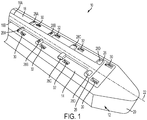
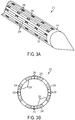
- Microfluidic convection-enhanced-delivery (CED) devices and methods of use are disclosed wherein the devices have an insertion support scaffold and a plurality of fluid delivery conduits extending longitudinally that are oriented to deliver a therapeutic agent in different directions. The conduits can also be used to aspirate fluid samples. In some embodiments, the conduits can be disposed on different side surfaces of the scaffold, e.g., circumferentially in a spaced-apart relationship around the side surface of the scaffold. In other embodiments, each conduit can also have a plurality of outlet ports spaced-apart from each other longitudinally and oriented to deliver therapeutic agents in different directions.
- Methods of treating neurological disorders are disclosed, but not claimed, whereby a microfluidic intraparenchymal delivery, neuro-ventricular delivery, or convection-enhanced-delivery (CED) probe is implanted into a brain of a patient (e.g., a human or animal), the probe comprising a semi-rigid or degradable scaffold and a fluid delivery conduit; and a fluid comprising at least one therapeutic agent under positive pressure is delivered through the conduit and into the brain. In various arrangements, the therapeutic agent can be a chemotherapeutic agent, an antibody, a nucleic acid construct, an RNAi agent, an antisense oligonucleotide or a gene therapy vector. In other arrangements, a cofactor such as a corticosteroid can be co-administered via the conduit with the therapeutic agent. The neurological disorders can include, without limitation, central- nervous-system (CNS) neoplasms, epilepsy, Parkinson's Disease, movement disorders, Huntington's Disease, ALS, Alzheimer's Disease, stroke, brain injury, and neurological diseases.
- Methods of delivering a therapeutic agent directly to a target site within a region of the central nervous system of a patient are disclosed but not claimed, using a plurality of microfluidic convection- enhanced-delivery (CED) probes whereby the probes are positioned in a spaced relationship around the target site such that one or more fluid outlet ports formed in the probes are aligned with the target site; and a fluid comprising a therapeutic agent under positive pressure is supplied through one or more fluid conduits formed in each of the plurality of probes to deliver the fluid through the one or more fluid outlet ports and into the target site. For example, the target site can be a tumor and the probes are inserted through either a single or multiple openings in the skull. In other arrangements, the pressure at which fluid is supplied to each of the plurality of probes can be adjusted based on feedback from a microsensor disposed within at least one of the plurality of probes.
- Methods of treating balance or hearing disorders are disclosed but not claimed, in which an opening is formed in a skull of a patient to access a portion of an ear of the patient, a microfluidic convection-enhanced-delivery (CED) probe is implanted into the portion of the ear, and a fluid comprising at least one therapeutic agent is delivered under positive pressure through the conduit and into the portion of the ear. In one arrangement, the probe can include a degradable scaffold and a fluid delivery conduit and the target region for therapy can be the inner ear, the cochlea, the organ of Corti or the basilar membrane. In another arrangement, the therapeutic agent can be a gene therapy vector, e.g., to deliver a human atonal gene. The method can further include delivering a cofactor, such as a corticosteroid, to the portion of the ear to improve fluid delivery.
- Methods of delivering a therapeutic agent to a target region within a spinal canal of a patient are disclosed, but not claimed, in which a microfluidic convection-enhanced-delivery (CED) probe is implanted into a target area, a fluid comprising the therapeutic agent under positive pressure is delivered through the conduit and into the target region, and substantially none of the delivered fluid mixes with cerebrospinal fluid (CSF) of the patient. In one arrangement, the probe includes a degradable scaffold and a fluid delivery conduit. In another arrangement, the therapeutic agent can include stem cells for the treatment of ALS.
- Microfluidic convection-enhanced-delivery (CED) devices are disclosed having a substrate; a conduit layer deposited on the substrate, the conduit layer defining therein at least one fluid delivery conduit with at least one fluid outlet port and a flow restriction formed within the at least one fluid delivery conduit at or near the outlet, the flow restriction being configured to adjust a pressure of fluid being directed through the at least one fluid delivery conduit. In certain embodiments, the flow restriction includes a constricted region of the at least one fluid delivery conduit having a cross-sectional area that is less than a cross-sectional area of a proximally-adjacent portion of the at least one fluid delivery conduit, and preferably at least about 20% less than the cross-sectional area of the proximally- adjacent portion.
- Methods of delivering a therapeutic agent during fetal surgery are disclosed, but not claimed, in which a microfluidic convection-enhanced-delivery (CED) probe is implanted into a target region of a fetus or a patient in which the fetus is disposed, the probe comprising a degradable scaffold and a fluid delivery conduit. In one arrangement, the method also includes delivering fluid comprising the therapeutic agent under positive pressure through the conduit and into the target region. The target region can be or can include an umbilical cord, an umbilical artery, an umbilical vein, a placenta, and/or a uterine wall. In one arrangement, the therapeutic agent comprises stem cells.
- In some embodiments, microfluidic CED devices are disclosed in which a plurality of fluid delivery conduits are provided having longitudinally staggered outlet ports. An inflatable member such as a reinforced conformable balloon can be coupled to and in fluid communication with one or more of the fluid delivery conduits. Methods of delivering a drug such as an anti- angiogenesis factor to a cavernous malformation are also disclosed herein. The method can include delivering the drug to the cavernous malformation using a microfluidic CED device and then inflating an inflatable member within the cavernous malformation to compress the drug into the surrounding tissue.
- A cavernous malformation (CCM) is a collection of small blood vessels (capillaries) in the central nervous system (CNS) that is enlarged and irregular in structure. In CCM, the walls of the capillaries are thinner than normal, less elastic, and prone to leaking. Cavernous malformations can occur anywhere in the body, but usually only produce symptoms when they are found in the brain and spinal cord. Some people with CCM - experts estimate 25 percent - will never experience any related medical problems. Others will have serious symptoms such as seizures (most commonly), headaches, paralysis, hearing or vision changes, and bleeding in the brain (cerebral hemorrhage).
- There are no effective cures for CCM. Seizures are usually treated with antiepileptic drugs. If seizures don't respond to medication, or there is recurring bleeding in the brain, surgical removal of the lesion(s) using microsurgical techniques is sometimes necessary.
- Cavernomas occur sporadically (spontaneously in a non-inherited manner) in the majority of cases, but in some cases may demonstrate inheritance (familial; i.e., a positive or strong family history of cavernous malformations). In familial cases, a specific chromosome 7 gene abnormality has been demonstrated, and familial cavernous malformation has been reported to be more common in Hispanic (especially Mexican- American) persons. In familial cases, cavernous malformations are more commonly multiple (i.e., two or more cavernomas present at the time of diagnosis), and may also involve the spinal cord.
- Cavernomas may be asymptomatic, or may present with seizures (60%) or with progressive neurological impairment or "deficits" (50%). Some can present with hydrocephalus or raised intracranial pressure (headache, nausea, vomiting, visual disturbance, sleepiness) depending on their size and location. It is uncommon for cavernomas to cause sudden catastrophic or devastating neurological injury, but the progressive brain (or spinal cord) injury associated with cavernomas may be severely disabling as time goes on.
- This is due at least in part to repeated bouts of hemorrhage in the cavernoma. Different cavities of the cavernoma may have different ages of blood products. The walls are fragile, and the growth of micro blood vessels into these lesions results in blood product (hemosiderin) leeching around the cavernoma, and cycles of cavernoma growth through hemorrhage and rehemorrhage. The hemorrhage is rarely a large devastating hemorrhage.
- Antiangiogenic therapy inhibits the growth of new blood vessels. Because new blood vessel growth plays a critical role in many disease conditions, including disorders that cause blindness, arthritis, and cancer, angiogenesis inhibition is a "common denominator" approach to treating these diseases. Antiangiogenic drugs exert their beneficial effects in a number of ways: by disabling the agents that activate and promote cell growth, or by directly blocking the growing blood vessel cells. Angiogenesis inhibitory properties have been discovered in more than 300 substances, ranging from molecules produced naturally in animals and plants, such as green tea extract, to new chemicals synthesized in the laboratory. A number of medicines already approved by the U.S. Food and Drug Administration (FDA) have also been found to possess antiangiogenic properties, including celecoxib (Celebrex), bortezomib (Velcade), and interferon. Many inhibitors are currently being tested in clinical trials for a variety of diseases in human patients, and some in veterinary settings.
- Rapamycin (now called Sirolimus) is a drug used to keep the body from rejecting organ and bone marrow transplants. It is now known that Rapamycin blocks certain white blood cells that can reject foreign tissues and organs (antiangiogenic). It also blocks a protein that is involved in cell division. It is a type of antibiotic, a type of immunosuppressant, and a type of serine/threonine kinase inhibitor.
- In one example, a microfluidic convection-enhanced-delivery (CED) device is provided that includes an insertion support scaffold having a proximal end and a distal end and a plurality of fluid delivery conduits extending longitudinally therethrough, each conduit having an inlet port and at least one outlet port. The plurality of conduits can be disposed near the distal end of the scaffold and oriented to deliver a therapeutic agent in different directions. The plurality of conduits can be configured to aspirate fluids.
- Each of the plurality of conduits can be coupled to a respective one of a plurality of side surfaces of the scaffold and/or the plurality of conduits can be positioned in a spaced relationship about a continuous circumferential side surface of the scaffold.
- The at least one outlet port can include a plurality of outlet ports spaced a distance apart from one another between proximal and distal ends of each conduit. Each of the plurality of outlet ports can have an area that is greater than an area of any outlet port positioned proximally thereto. The plurality of conduits can be formed from at least one of a parylene composition, a silastic composition, a polyurethane composition, and a PTFE composition, and/or can be disposed within a plurality of corresponding recesses formed in the scaffold.
- The device can also include a fluid reservoir in fluid communication with the inlet ports of the plurality of conduits and configured to supply a fluid thereto under positive pressure. The plurality of conduits can be flexible.
- At least one of the plurality of conduits can include an embedded microsensor, which can include at least one of an interrogatable sensor, a pressure sensor a glutamate sensor, a pH sensor, a temperature sensor, an ion concentration sensor, a carbon dioxide sensor, an oxygen sensor, and a lactate sensor.
- The scaffold can be rigid, semi-rigid, and/or degradable, and the distal end of the scaffold can have an atraumatic shape configured to penetrate tissue without causing trauma. The scaffold can be formed from a degradable thermoplastic polymer (e.g., a degradable thermoplastic polyester and/or a degradable thermoplastic polycarbonate). In one embodiment, the scaffold is formed from poly(lactic-co-glycolic acid) (PLGA).
- The scaffold can contain a quantity of a drug, can be coated with a drug, and/or can be impregnated with at least one of an antibacterial agent and an anti-inflammatory agent. For example, the scaffold can be impregnated with a corticosteroid, such as dexamethasone.
- Each of the plurality of conduits can be in fluid communication with a respective micro- capillary tube. The scaffold can include a body and an elongate distal tip, and the device can further include a nose disposed at an interface between the body and the distal tip such that the nose encapsulates a distal portion of the body.
- Also disclosed herein, but not claimed, is a method of delivering a therapeutic agent to a brain of a patient is provided that includes forming an opening through a skull of the patient, advancing a scaffold through the opening in the skull and into the brain, and supplying a fluid comprising the therapeutic agent under positive pressure to a plurality of fluid delivery conduits, each of the plurality of conduits being coupled to a respective side surface of the scaffold. The method also includes ejecting the fluid from one or more outlet ports formed in each of the plurality of conduits to deliver the fluid to the brain in a radial pattern substantially 360 degrees around the scaffold.
- The method can also include allowing the scaffold to degrade within the brain and thereby release a corticosteroid impregnated in the scaffold and/or delivering an enzyme through the plurality of conduits in unison with the fluid to enhance penetration of the therapeutic agent into the brain.
- Further disclosed, but not claimed, is a method of delivering a therapeutic agent to a patient is provided. The method can include advancing a scaffold into a target region of the patient, supplying a fluid comprising the therapeutic agent under positive pressure to a plurality of fluid delivery conduits, each of the plurality of conduits being coupled to a respective side surface of the scaffold, and ejecting the fluid from one or more outlet ports formed in each of the plurality of conduits to deliver the fluid to the target region in multiple directions.
- The method can include allowing the scaffold to degrade and thereby release a corticosteroid impregnated in the scaffold. The method can include delivering an enzyme through the plurality of conduits in unison with the fluid to enhance penetration of the therapeutic agent into the target region. In some methods, ejecting the fluid can include delivering the fluid to the target region in a radial pattern substantially 360 degrees around the scaffold. The method can be used to treat at least one condition selected from central-nervous- system (CNS) neoplasm, intractable epilepsy, Parkinson's disease, Huntington's disease, stroke, lysosomal storage disease, chronic brain injury, Alzheimer's disease, amyotrophic lateral sclerosis, balance disorders, hearing disorders, and cavernous malformations.
- Also disclosed, but not claimed, is a method of treating central-nervous-system (CNS) neoplasm is provided that includes implanting a microfluidic convection-enhanced-delivery (CED) probe into a brain of a patient, the probe comprising a degradable scaffold and a fluid delivery conduit, and delivering fluid comprising at least one therapeutic agent under positive pressure through the conduit and into the brain.
- The therapeutic agent can include at least one of an antibody (e.g., an anti-epidermal growth factor (EGF) receptor monoclonal antibody) and a nucleic acid construct (e.g., a ribonucleic acid interference (RNAi) agent, an antisense oligonucleotide, a viral vector, an adenovirus, and/or an adeno-associated viral vector). The method can also include delivering a cofactor to the brain to improve fluid delivery. The cofactor can include at least one of a corticosteroid impregnated in the scaffold, a corticosteroid coated onto the scaffold, and a propagation enhancing enzyme.
- Also disclosed, but not claimed is a method of treating intractable epilepsy is provided that includes implanting a microfluidic convection-enhanced- delivery (CED) probe into a brain of a patient, the probe comprising a degradable scaffold and a fluid delivery conduit, and delivering fluid comprising an anti-convulsive agent under positive pressure through the conduit and into the brain.
- Also disclosed, but not claimed, is a method of treating Parkinson's disease is provided that includes implanting a microfluidic convection-enhanced- delivery (CED) probe into a brain of a patient, the probe comprising a degradable scaffold and a fluid delivery conduit, and delivering fluid comprising a protein under positive pressure through the conduit and into the brain. The protein can include glial cell-derived neurotrophic factor (GDNF) or brain-derived neurotrophic factor (BDNF) or genetic materials.
- Also disclosed, but not claimed, is a method of treating Huntington's disease is provided that includes implanting a microfluidic convection-enhanced- delivery (CED) probe into a brain of a patient, the probe comprising a degradable scaffold and a fluid delivery conduit, and delivering fluid comprising a nucleic acid construct under positive pressure through the conduit and into the brain. The nucleic acid construct can include at least one of a ribonucleic acid interference (RNAi) agent and an antisense oligonucleotide.
- Also disclosed, but not claimed is, a method of treating stroke is provided that includes implanting a microfluidic convection-enhanced-delivery (CED) probe into a brain of a patient, the probe comprising a degradable scaffold and a fluid delivery conduit, and delivering fluid comprising a neurotrophin under positive pressure through the conduit and into the brain.
- Also disclosed, but not claimed, is a method of treating lysosomal storage disease is provided that includes implanting a microfluidic convection- enhanced-delivery (CED) probe into a brain of a patient, the probe comprising a degradable scaffold and a fluid delivery conduit, and delivering fluid comprising a protein under positive pressure through the conduit and into the brain. The protein can include lysosomal enzymes.
- Also disclosed, but not claimed, is a method of treating chronic brain injury is provided that includes implanting a microfluidic convection-enhanced- delivery (CED) probe into a brain of a patient, the probe comprising a degradable scaffold and a fluid delivery conduit, and delivering fluid comprising a protein under positive pressure through the conduit and into the brain. The protein can include at least one of brain-derived neurotrophic factor (BDNF) and fibroblast growth factor (FGF).
- Also disclosed, but not claimed, is a method of treating Alzheimer's disease is provided that includes implanting a microfluidic convection-enhanced- delivery (CED) probe into a brain of a patient, the probe comprising a degradable scaffold and a fluid delivery conduit, and delivering fluid comprising at least one of anti-amyloids and nerve growth factor (NGF), or genes or vectors, under positive pressure through the conduit and into the brain.
- Also disclosed, but not claimed, is a method of treating amyotrophic lateral sclerosis is provided that includes implanting a microfluidic convection- enhanced-delivery (CED) probe into a brain of a patient, the probe comprising a degradable scaffold and a fluid delivery conduit, and delivering fluid comprising a protein under positive pressure through the conduit and into the brain. The protein can include at least one of brain- derived neurotrophic factor (BDNF) and ciliary neurotrophic factor (CNTF).
- Also disclosed, but not claimed, is a method of delivering a therapeutic agent to a target region within a spinal canal of a patient is provided that includes implanting a microfluidic convection-enhanced-delivery (CED) probe into the target area, the probe comprising a degradable scaffold and a fluid delivery conduit, and delivering fluid comprising the therapeutic agent under positive pressure through the conduit and into the target region. In one arrangement, substantially none of the fluid mixes with cerebrospinal fluid (CSF) of the patient. The therapeutic agent can include stem cells for the treatment of ALS.
- Also disclosed, but not claimed, is a method of delivering a therapeutic agent to a target site within a brain of a patient using a plurality of microfluidic convection-enhanced-delivery (CED) probes is provided. The method includes positioning the plurality of probes in a spaced relationship around the target site such that one or more fluid outlet ports formed in each of the plurality of probes are aligned with the target site. The method also includes supplying a fluid comprising the therapeutic agent under positive pressure through one or more fluid conduits formed in each of the plurality of probes to deliver the fluid through the one or more fluid outlet ports and into the target site.
- In one arrangement, the target site can include a tumor. The plurality of probes can be inserted through a single opening in the skull or can be inserted through separate openings in the skull. The method can also include adjusting a respective pressure at which fluid is supplied to each of the plurality of probes based on feedback from a microsensor disposed within at least one of the plurality of probes. The microsensor can include at least one of an interrogatable sensor, a pressure sensor, a glutamate sensor, a pH sensor, a temperature sensor, an ion concentration sensor, a carbon dioxide sensor, an oxygen sensor, and a lactate sensor.
- In an example, a microfluidic convection- enhanced-delivery (CED) device is provided that includes a substrate, a conduit layer deposited on the substrate, the conduit layer having formed therein at least one fluid delivery conduit having a proximal end, a distal end, a fluid inlet port, and at least one fluid outlet port, and a flow restriction formed within the at least one fluid delivery conduit at or near the distal end thereof, the flow restriction being configured to adjust a pressure of fluid being directed through the at least one fluid delivery conduit.
- The device can also include an insertion support scaffold to which the substrate is coupled. The substrate can be formed from silicon and the conduit layer can be formed from parylene. In one example, the flow restriction includes a constricted region of the at least one fluid delivery conduit having a cross-sectional area that is less than a cross-sectional area of a proximally- adjacent portion of the at least one fluid delivery conduit.
- The cross-sectional area of the constricted region can be approximately 20% less, approximately 30% less, or approximately 40% less than the cross-sectional area of the proximally- adjacent portion.
- In one example, the proximally- adjacent portion has a height between about 1 micron and about 50 microns and the constricted region has a height between about 1 micron and about 25 microns. In another example, the proximally- adjacent portion has a width between about 10 microns and about 100 microns and the constricted region has a width between about 5 microns and about 50 microns.
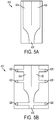
- The at least one fluid outlet port can include a plurality of outlet ports spaced a distance apart from one another between proximal and distal ends of the at least one fluid delivery conduit. Each of the plurality of outlet ports can have an area that is greater than an area of any outlet port positioned proximally thereto. The at least one fluid delivery conduit can be formed from at least one of a parylene composition, a silastic composition, a polyurethane composition, and a PTFE composition. The device can also include a fluid reservoir in fluid communication with the fluid inlet ports of the at least one fluid delivery conduit and configured to supply a fluid thereto under positive pressure. The at least one fluid delivery conduit can include an embedded microsensor. The embedded microsensor can include at least one of an interrogatable sensor, a pressure sensor, a glutamate sensor, a pH sensor, a temperature sensor, an ion concentration sensor, a carbon dioxide sensor, an oxygen sensor, and a lactate sensor. The at least one fluid delivery conduit can be configured to aspirate fluids.
- Also disclosed, but not claimed, is a method of delivering a therapeutic agent to a patient is provided. The method can include advancing a substrate to a target region of the patient, the substrate having at least one fluid delivery conduit, the at least one fluid delivery conduit including a flow restriction formed at or near a distal end thereof configured to adjust a pressure of fluid being directed through the at least one fluid delivery conduit. The method can also include supplying a fluid comprising the therapeutic agent under positive pressure to the at least one fluid delivery conduit. The method can also include ejecting the fluid from one or more outlet ports formed in the at least one fluid delivery conduit to deliver the fluid to the target region. The method can also include delivering an enzyme through the at least one fluid delivery conduit in unison with the fluid to enhance penetration of the therapeutic agent into the target region. In some arrangements, the method can be used to treat at least one condition selected from central-nervous- system (CNS) neoplasm, intractable epilepsy, Parkinson's disease, Huntington's disease, stroke, lysosomal storage disease, chronic brain injury, Alzheimer's disease, amyotrophic lateral sclerosis, balance disorders, hearing disorders, and cavernous malformations.
- Also disclosed, but not claimed, is a method of treating balance or hearing disorders is provided that includes forming an opening in a skull of a patient to access a portion of an ear of the patient and implanting a micro fluidic convection-enhanced- delivery (CED) probe into the portion of the ear, the probe comprising a degradable scaffold and a fluid delivery conduit. The method also includes delivering fluid comprising at least one therapeutic agent under positive pressure through the conduit and into the portion of the ear.
- The portion of the ear can include any one or more of an inner ear, a cochlea, an organ of Corti, and a basilar membrane. The therapeutic agent can include human atonal gene. Also disclosed, but not claimed, is the method also includes delivering a cofactor to the portion of the ear to improve fluid delivery. The cofactor can include at least one of a corticosteroid impregnated in the scaffold, a corticosteroid coated onto the scaffold, and a propagation enhancing enzyme. In one arrangement, the method also includes allowing the scaffold to degrade within the portion of the ear and thereby release a corticosteroid impregnated in the scaffold.
- Also disclosed, but not claimed, is a method of delivering a therapeutic agent during fetal surgery is provided that includes implanting a microfluidic convection-enhanced-delivery (CED) probe into a target region of a fetus or a patient in which the fetus is disposed, the probe comprising a degradable scaffold and a fluid delivery conduit. The method also includes delivering fluid comprising the therapeutic agent under positive pressure through the conduit and into the target region.
- The target region can be or can include an umbilical cord, an umbilical artery, an umbilical vein, a placenta, and/or a uterine wall. In one embodiment, the therapeutic agent comprises stem cells.
- In another example, a microfluidic convection- enhanced-delivery (CED) device is provided that includes an insertion support scaffold having a proximal end and a distal end, a shank coupled to the support scaffold, a first fluid delivery conduit extending longitudinally through the shank having an inlet port and at least one outlet port, and a second fluid delivery conduit extending longitudinally through the shank having an inlet port and at least one outlet port. The at least one outlet port of the second fluid delivery conduit is spaced longitudinally a distance apart from the at least one outlet port of the first fluid delivery conduit.
- In some examples, the at least one outlet port of the second fluid delivery conduit is disposed closer to the distal end of the shank than the at least one outlet port of the first fluid delivery conduit. The scaffold can have a width in the range of about 0.02 µιη to about 2000 µιη and/or can be rigid, semi-rigid, and/or partially or fully degradable. The first and second fluid delivery conduits can each have a diameter in the range of about 0.02 µιη to about 500 µιη.
- In some examples, the device can include an inflatable member coupled to the shank, an interior of the inflatable member being in fluid communication with the first fluid delivery conduit via the at least one outlet port of the first fluid delivery conduit. The inflatable member can be or can include a reinforced conformable balloon. The inflatable member can have at least a deflated configuration in which it occupies a first volume and an inflated configuration in which it occupies a second volume that is greater than the first volume.
- The device can be MRI and stereotactic surgery compatible, can include at least one radiopaque marker, and/or can include a microsensor embedded in at least one of the first and second fluid delivery conduits.
- Also disclosed, but not claimed, is a method of delivering a drug to a cavernous malformation within a patient is provided. The method includes implanting a microfluidic convection-enhanced-delivery (CED) probe into the cavernous malformation, the probe comprising an insertion scaffold and at least one fluid delivery conduit, and delivering fluid comprising the drug under positive pressure through the at least one fluid delivery conduit and into the cavernous malformation.
- In some examples, the drug can include one or more antiangio genesis compounds, such as celecoxib, bortezomib, interferon, and/or rapamycin. The drug can include nanoparticles encapsulated with therapeutic molecules or antiangiogenesis compounds.
- In some examples, the at least one fluid delivery conduit comprises a first fluid delivery conduit having an outlet port formed therein and a second fluid delivery conduit having an outlet port formed therein. The probe can be implanted such that the outlet port of the first fluid delivery conduit is disposed at the surface of the cavernous malformation and the outlet port of the second fluid delivery conduit is disposed within the core of the cavernous malformation. The method can also include delivering the fluid under positive pressure to the surface of the cavernous malformation via the first fluid delivery conduit and to the core of the cavernous malformation via the second fluid delivery conduit.
- The probe can be implanted such that the outlet port of the first fluid delivery conduit is disposed within the core of the cavernous malformation and the outlet port of the second fluid delivery conduit is disposed within the core of the cavernous malformation. The method can also include delivering the fluid under positive pressure to the core of the cavernous malformation via the second fluid delivery conduit and then inflating a balloon in fluid communication with the outlet port of the first fluid delivery conduit to apply pressure to the fluid and force it into the surrounding cavernous malformation.
- In some examples, the drug can include a hydrogel or other substance having adhesive properties. The cavernous malformation can be formed in the central nervous system of the patient. The drug can be formulated to tamponade and/or completely coat the cavernous malformation. The probe can include a balloon at the distal end operable to compress the drug into the cavernous malformation. The method can include adjusting delivery of the fluid based on feedback from at least one microsensor embedded in the probe.
- Also disclosed, but not claimed, is a method of delivering a therapeutic agent to a patient is provided. The method can include advancing a microfluidic convection-enhanced-delivery (CED) device into a target region of the patient, the CED device including an insertion support scaffold having a proximal end and a distal end, a shank coupled to the support scaffold, a first fluid delivery conduit extending longitudinally through the shank having an inlet port and at least one outlet port, and a second fluid delivery conduit extending longitudinally through the shank having an inlet port and at least one outlet port, the at least one outlet port of the second fluid delivery conduit being spaced longitudinally a distance apart from the at least one outlet port of the first fluid delivery conduit. The method can also include supplying a fluid comprising the therapeutic agent under positive pressure to at least one of the first and second fluid delivery conduits. The method can also include ejecting the fluid from at least one of the first and second fluid delivery conduits to deliver the fluid to the target region. The method can also include inflating an inflatable member in the target region to augment delivery of the therapeutic agent.
- The method can include allowing the scaffold to degrade and thereby release a corticosteroid impregnated in the scaffold. The method can be used to treat at least one condition selected from central-nervous-system (CNS) neoplasm, intractable epilepsy, Parkinson's disease, Huntington's disease, stroke, lysosomal storage disease, chronic brain injury, Alzheimer's disease, amyotrophic lateral sclerosis, balance disorders, hearing disorders, and cavernous malformations.
- Also disclosed, but not claimed, is a method of fabricating a delivery device having at least one fluid channel is provided. The method can include depositing an oxide mask on a backside of a silicon wafer, patterning the oxide mask to define a perimeter of the delivery device, depositing a polyimide layer on a frontside of the silicon wafer, depositing sacrificial resist on the polyimide layer in a shape of the at least one fluid channel, depositing a parylene layer over the sacrificial resist and the polyimide layer, depositing an aluminum mask over the parylene layer, and removing the sacrificial resist using a solvent to form the at least one fluid channel between the polyimide layer and the parylene layer.
- The method can also include coupling a micro-capillary tube to the delivery device such that the micro-capillary tube is in fluid communication with the at least one fluid channel. The method can also include etching a trench into the backside of the silicon wafer according to the patterned oxide mask. The method can also include applying an oxide etch stop to the floor of the trench.
- Also disclosed, but not claimed, is a method of fabricating a delivery device having at least one fluid channel is provided. The method can include etching a frontside of a silicon wafer to define a perimeter of the delivery device, applying a polyimide coat to the frontside of the silicon wafer and to a backside of the silicon wafer, applying sacrificial resist to the polyimide coat in a shape of the at least one fluid channel, applying a parylene layer over the sacrificial resist, depositing an aluminum mask over the parylene layer, and removing the sacrificial resist using a solvent to form the at least one fluid channel between the polyimide coat and the parylene layer.
- The method can also include coupling a micro-capillary tube to the delivery device such that the micro-capillary tube is in fluid communication with the at least one fluid channel.
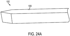
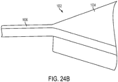
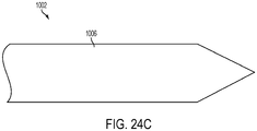
- In the embodiment of the invention, a microfluidic convection- enhanced-delivery (CED) device is provided. The device includes a substrate that defines a body, an elongate distal tip, and first and second proximal legs. The device includes also a first fluid channel that extends along the first leg, along the body, and along the distal tip, and a second fluid channel that extends along the second leg, along the body, and along the distal tip. The device includes further a first micro-capillary tube coupled to the first leg portion and in fluid communication with the first fluid channel, and a second micro-capillary tube coupled to the second leg portion and in fluid communication with the second fluid channel. The device comprises a tubular sheath that encapsulates the first and second legs and at least a portion of the first and second micro-capillary tubes.
- In some embodiments, the device can include a nose disposed at an interface between the distal tip and the body that encapsulates a distal portion of the body. The nose can be conical or hemispherical.
- The invention will be more fully understood from the following detailed description taken in conjunction with the accompanying drawings, in which:
-
FIG. 1 is a perspective schematic view of one exemplary microfabricated CED device; -
FIG. 2A is a perspective schematic view of another exemplary microfabricated CED device; -
FIG. 2B is a cross-sectional view of the microfabricated CED device ofFIG. 2A ; -
FIG. 3A is a perspective schematic view of another exemplary microfabricated CED device; -
FIG. 3B is a cross-sectional view of the microfabricated CED device ofFIG. 3A ; -
FIG. 4 is a schematic diagram of a fluid delivery system operatively coupled to a microfabricated CED device; -
FIG. 5A is a schematic top view of one exemplary fluid delivery conduit of a microfabricated CED device; -
FIG. 5B is a schematic top view of another exemplary fluid delivery conduit of a microfabricated CED device; -
FIG. 6 is a electron micrograph of another exemplary microfabricated CED device; -
FIG. 7 is a schematic diagram of a microfabricated CED device implanted into a brain of a patient; -
FIG. 8 is a perspective view of a microfabricated CED device coupled to a standard cannula; -
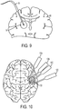
FIG. 9 is a schematic diagram of a microfabricated CED device implanted into a brain of a patient and an associated fluid release spatial distribution pattern; -
FIG. 10 is a schematic diagram of a plurality of microfabricated CED devices positioned to surround a target site within a brain of a patient; -
FIG. 11 is an electron micrograph of another exemplary microfabricated CED device; -
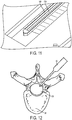
FIG. 12 is a schematic diagram of a microfabricated CED device implanted into a spinal canal of a patient; -
FIG. 13 is a schematic cross-sectional view of a microfabricated CED device implanted into an inner ear of a patient; -
FIG. 14 is a schematic side view of a microfabricated CED device implanted into an inner ear of a patient; -
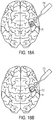
FIG. 15 is a schematic view of microfabricated CED devices implanted into various regions of a brain; -
FIG. 16 is a schematic view of a microfabricated CED device implanted into a target region during fetal surgery; -
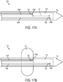
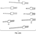
FIG. 17A is a schematic view of a microfabricated CED device having fluid delivery conduits with longitudinally staggered outlet ports; -
FIG. 17B is a schematic view of a microfabricated CED device having longitudinally staggered outlet ports and an inflatable member; -
FIG. 18A is a schematic view of the device ofFIG. 17B inserted into a cavernous malformation; -
FIG. 18B is a schematic view of the device ofFIG, 17B with the inflatable member inflated within the cavernous malformation; -
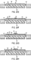
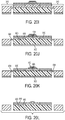
FIG. 19 is a flowchart that depicts an exemplary method of manufacturing a microfabricated CED device; -
FIGS. 20A-20L are cross-sectional views of a CED device at various stages of the process ofFIG. 19 ; -
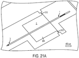
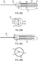
FIG. 21A is a scanning electron microscope image of a microfabricated CED device; -
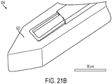
FIG. 21B is a scanning electron microscope image of the distal tip of the CED device ofFIG. 21A ; -
FIG. 22A is a schematic top view of a microfabricated CED device according to the claimed invention; -
FIG. 22B is a detail schematic top view of the distal tip of the CED device ofFIG. 22A ; -
FIG. 23A is a schematic view of a wafer layout that includes a plurality of microfabricated CED devices; -
FIG. 23B is a schematic view of the wafer layout ofFIG. 23A repeated a plurality of times on a silicon wafer; -
FIG. 23C is an image of a plurality of microfabricated CED devices produced using the layout ofFIG. 23A ; -
FIG. 24A is a microscope image of a silicon substrate formed during manufacture of a CED device; -
FIG. 24B is another microscope image of the substrate ofFIG. 24A ; -
FIG. 24C is another microscope image of the substrate ofFIG. 24A ; -
FIG. 25A is a schematic top view of a microfabricated CED device having an attached catheter portion; -
FIG. 25B is a schematic end view of the device ofFIG. 25A ; -
FIG. 25C is a schematic top view of the device ofFIG. 25A with a nose portion and catheter body coupled thereto; -
FIG. 25D is a schematic end view of the device ofFIG. 25C ; -
FIG. 26A is a top view image of an assembled CED device; -
FIG. 26B is a perspective view image of the CED device ofFIG. 26A ; and -
FIG. 26C is a top view image of the CED device ofFIG. 26A shown with a reference scale. - Certain examples will now be described to provide an overall understanding of the principles of the structure, function, manufacture, and use of the methods, systems, and devices disclosed herein. Examples and embodiments are illustrated in the accompanying drawings. Those skilled in the art will understand that the methods, systems, and devices specifically described herein and illustrated in the accompanying drawings are non-limiting and that the scope of the present invention is defined solely by the claims.
- The methods, systems, and devices disclosed herein generally involve convection-enhanced delivery of drugs to a target region within a patient. Microfluidic catheter devices are disclosed that are particularly suitable for targeted delivery of drugs via convection, including devices capable of multi-directional drug delivery and devices that control fluid pressure and velocity using the venturi effect. Methods of treating various diseases using such devices are also disclosed, including methods of treating cerebral and spinal cavernous malformations, cavernomas, and hemangiomas, methods of treating neurological diseases, methods of treatment using multiple microfluidic delivery devices, methods of treating hearing disorders, methods of spinal drug delivery using microfluidic devices, and methods of delivering stem cells and therapeutics during fetal surgery. Methods of manufacturing such devices are also disclosed.
- The term "drug" as used herein refers to any functional agent that can be delivered to a human or animal patient, including hormones, stem cells, gene therapies, chemicals, compounds, small and large molecules, dyes, antibodies, viruses, therapeutic agents, etc. The terms "microfabricated CED device," "microfluidic delivery device," "CED device," "probe," "microprobe," "catheter," and "microcatheter" are generally used interchangeably herein.
- Exemplary CED methods and devices are disclosed in
U.S. Publication No. 2010/0098767, filed on July 31, 2009 . -
FIG. 1 illustrates one exemplarymicrofabricated CED device 10. Thedevice 10 generally includes asupport scaffold 12 to which one ormore shank portions 14 are coupled. Theshank portions 14 can include one of more fluid delivery conduits 16 formed thereon or therein. - The illustrated
support scaffold 12 is generally formed by an elongate body having aproximal end 18, adistal end 20, and a longitudinal axis 22 extending therebetween. A cross-section of the illustratedscaffold 12 taken in a plane normal to the longitudinal axis 22 has a substantially rectangular shape, however any of a variety of cross-sectional shapes can be used, including circular, hexagonal, and elliptical. Thescaffold 12 can provide structural rigidity to thedevice 10 to facilitate insertion into target tissue. To assist with tissue penetration and navigation, thedistal end 20 of thesupport scaffold 12 can be tapered, pointed, and/or sharpened. In the illustrated example, thescaffold 12 is provided with a rounded atraumatic tip so as to facilitate insertion through tissue without causing trauma to the tissue. - The
support scaffold 12 can be rigid or semi-rigid and can be formed from a degradable thermoplastic polymer, for example, a degradable thermoplastic polyester or a degradable thermoplastic polycarbonate. In one example, thesupport scaffold 12 is formed from poly(lactic-co-glycolic acid) (PLGA) and is configured to biodegrade within the target tissue. This can advantageously eliminate the need to remove thesupport scaffold 12 once thedevice 10 is positioned within target tissue, thereby avoiding the potential to disrupt the positioning of the fluid delivery conduits 16. Any of a variety of other materials can also be used to form thesupport scaffold 12, including silicon or various ceramics, metals, and plastics known in the art. - The
support scaffold 12 can contain or can be impregnated with a quantity of a drug. Alternatively, or in addition, a surface of thesupport scaffold 12 can be coated with a drug. Exemplary drugs include anti-inflammatory components, drug permeability-increasing components, delayed-release coatings, and the like. In one example, thescaffold 12 can be coated or impregnated with a corticosteroid such as dexamethasone which can prevent swelling around the injection site and disruptions to the fluid delivery pattern that can result from such swelling. - The
scaffold 12 can have a width of approximately 100 µm to approximately 200 µm and can have a length that varies depending on the target tissue (e.g., depending on the depth at which the target tissue is situated). In one example, thescaffold 12 is between 2 cm and 3 cm long. - The
scaffold 12 can also include a recess or shelf portion 24 configured to retain or mate with theshank portion 14 of thedevice 10. In addition, as described further below, thescaffold 12 can include multiple recesses or shelf portions for coupling to a plurality ofshank portions 14. In this case, the recesses or shelf portions can be formed on multiple different surfaces of the scaffold. A variety of techniques can be used to couple theshank portion 14 to thesupport scaffold 12, such as surface tension from a water drop, adhesives, and/or a biocompatible petroleum jelly. - The
device 10 can also include one ormore shank portions 14 that are matable to thesupport scaffold 12. Theshank portion 14 can be a flexible substrate having one or more fluid delivery conduits 16 formed therein or thereon. Theshank portion 14 can be formed from any of a variety of materials, such as silicon or Parylene. - One or more fluid delivery conduits 16 can be formed in or on the
shank portion 14 of the device. The conduits 16 can extend along a surface of theshank portion 14 in a direction that is generally parallel to the longitudinal axis 22 of thescaffold 12, and can have one or morelateral portions 26 extending in a direction that forms a non-zero angle with the longitudinal axis 22. - Each conduit 16 can include a fluid inlet port (not shown in
FIG. 1 ) and one or more fluid outlet ports 28. The fluid inlet port can be positioned at a proximal end of thedevice 10, and can allow the conduit 16 to be placed in fluid communication with a fluid reservoir, e.g., via one or more pumps, meters, valves, or other suitable control devices. Such control devices can be used to regulate the pressure at which fluid is supplied to thedevice 10, or the rate or volume of fluid that is supplied to thedevice 10. - Fluid supplied to the conduit 16 though the fluid inlet port is directed through an inner lumen of the conduit and released through the one or more fluid outlet ports 28. The fluid outlet ports 28 can be sized, shaped, and/or positioned to control various release parameters of the fluid. For example, the fluid outlet ports 28 can be configured to control the direction in which fluid is release from the
device 10, the distribution of the fluid within the target tissue, and the velocity or pressure at which the fluid is released. - In the illustrated example, the
shank portion 14 includes first andsecond parylene conduits conduits lateral extensions 26 in which fluid outlet ports 28 are formed. The size of the fluid outlet ports 28 progressively increases towards thedistal end 20 of thedevice 10, which can advantageously compensate for pressure loss that occurs along the length of the device such that fluid is released from each of the plurality of fluid outlet ports 28 at substantially the same pressure. The illustrated fluid outlet ports 28 are also shaped to control the release direction of the fluid. Theports ports device 10. - The device can also include one or
more sensors 30 mounted in or on theshank portion 14 or on thescaffold 12. Thesensors 30 can include temperature sensors, pH sensors, pressure sensors, oxygen sensors, tension sensors, interrogatable sensors, glutamate sensors, ion concentration sensors, carbon dioxide sensors, lactate sensors, neurotransmitter sensors, or any of a variety of other sensor types, and can provide feedback to a control circuit which can in turn regulate the delivery of fluid through thedevice 10 based on one or more sensed parameters. One ormore electrodes 32 can also be provided in or on theshank portion 14 or thesupport scaffold 12, which can be used to deliver electrical energy to target tissue, e.g., to stimulate the target tissue or to ablate the target tissue. In one example, electrical energy is delivered through theelectrodes 32 while a drug is simultaneously delivered through the fluid delivery conduits 16. - The
device 10 can be used for CED of drugs to treat disorders of the brain, ears, other neural tissue, or other parts of a human or animal body. When used in the brain, thedevice 10 can circumvent the blood-brain barrier (BBB) by infusing drugs under positive pressure directly into tissue. Thedevice 10 provides a number of advantages, such as 1) a smaller cross-sectional area compared with conventional needles used in CED; 2) less disturbance to tissue when inserted into the brain than conventional needles; 3) the elimination of backflow or reflux along the outside of the inserted part, which in turn, permits higher rates of drug delivery in thedevice 10 compared with conventional needles; 4) minimal or no occlusion of the fluid delivery conduits 16 during insertion into the brain; 5) multiple parylene conduits 16 can be fabricated into thesilicon shank 14, each conducting a distinct fluid (drug), which allows simultaneous, sequential, or programmed delivery of multiple agents; 6) thedevice 10 has the potential to serve simultaneously as a drug delivery system and as a sensor-equipped probe to measure local tissue characteristics such as, but not limited to, pressure, pH, ion-specific concentrations, location, and other parameters; and 7) thedevice 10 allows for directional control of the drug release pattern. - The
device 10 can be functionally attached to the distal end of a long, thin insertion vehicle such as a cannula or a needle in or on which a fluid attachment could be made to the fluid inlet ports of the device's fluid delivery conduits 16. This can be especially advantageous in applications involving penetration of relatively thick tissue, e.g., insertion through a human skull. - In addition to delivering a drug-containing fluid, the
device 10 can also be used to deliver enzymes or other materials to modify tissue permeability and improve drug distribution in the targeted tissue. For example, penetration of a drug-containing nanoparticles into brain tissue can be enhanced by enzymatic digestion of at least one brain extracellular matrix component and intracranial infusion of the nanoparticle into the brain tissue. In another example, at least one enzyme can be immobilized to a surface of the nanoparticle during the step of enzymatic digestion. Thedevice 10 can provide the ability to deliver enzymatic and/or other materials that can, e.g., modify the drug delivery site, and therapeutic materials, in virtually any order, sequencing, and/or timing without the need to use different delivery devices and the potential complications involved in doing so. - The
device 10 can also be used to biopsy tissue, for example by passing a stylet or a grasping tool through one of the conduits 16 to a target site and then withdrawing the stylet or grasping tool from the target site with a biopsy specimen therein. In some examples theshank portions 14 or thesupport scaffold 12 can have a larger-diameter lumen extending therethrough for biopsy purposes, with smaller fluid conduits 16 formed on the exterior thereof. -
FIGS. 2A and 2B illustrate another exemplarymicrofabricated CED device 110. Thedevice 110 includes arectangular support scaffold 112 withshank portions 114 and accompanyingfluid delivery conduits 116 coupled to each of the four side surfaces thereof. As shown in the cross-sectional view ofFIG. 2B , theshank portions 114 are disposed within correspondingrecesses 124 formed in the sidewalls of thesupport scaffold 112. In an alternative example, theshank portions 114 can be surface mounted on thescaffold 112. Positioning ofshank portions 114 andfluid delivery conduits 116 on each of the four side surfaces of thescaffold 112 can further facilitate 360 degree convective flow of drug-containing fluid from thedevice 110. - The structure and function of the
device 110 is otherwise substantially the same as that of thedevice 10 described above, and therefore a further description thereof is omitted here for the sake of brevity. -
FIGS. 3A and 3B illustrate another exemplarymicrofabricated CED device 210. Thedevice 210 includes acylindrical support scaffold 212 withshank portions 214 and accompanyingfluid delivery conduits 216 coupled in a spaced relationship about the outer surface of thescaffold 212. As shown in the cross-sectional view ofFIG. 3B , theshank portions 214 are disposed within correspondingrecesses 224 formed in the sidewalls of thesupport scaffold 212. In an alternative example, theshank portions 214 can be surface mounted on thescaffold 212. It will be appreciated that the flexible nature of theshank portions 214 and thefluid delivery conduits 216 permits them to be curved or otherwise contoured to match the surface profile of thescaffold 212. Positioning ofshank portions 214 andfluid delivery conduits 216 about the outer surface of thescaffold 212 as shown can further facilitate 360 degree convective flow of drug-containing fluid from the device. - The structure and function of the
device 210 is otherwise substantially the same as that of thedevice 10 described above, and therefore a further description thereof is omitted here for the sake of brevity. -
FIG. 4 is a schematic illustration of adrug delivery system 300 that includes amicrocatheter CED device 310 which can be any of thedevices system 300 includes areservoir 302 of a drug-containing fluid that is coupled to apump 304 via acontrol valve 306. When the control valve is opened, fluid in thereservoir 302 is supplied under pressure by thepump 304 to apressure regulator 308, which can adjust a pressure at which the fluid is supplied to thecatheter 310. Thecontrol valve 306, pump 304, andregulator 308 can be operatively coupled to acontroller 301 which can include a microprocessor and a memory and can be configured to execute a drug-delivery control program stored in a non-transitory computer-readable storage medium. Thecontroller 301 can be configured to open or close thevalve 306, to turn thepump 304 on or off, to change an output pressure of thepump 304, and/or to adjust a pressure set point of theregulator 308. Thecontroller 301 can also receive information indicative of a sensed parameter via a feedback loop that includes one ormore sensors 330 mounted in or on thecatheter 310. Thus, in response to feedback from one ormore sensors 330 implanted with thecatheter 310, thecontroller 301 can start or stop the flow of fluid to thecatheter 310, increase or decrease the pressure at which fluid is supplied to thecatheter 310, etc. In one example, thecatheter 310 includes apressure sensor 330 that measures a fluid pressure in the vicinity of thecatheter 310 and thecontroller 301 is configured to maintain the fluid supply pressure at a substantially constant level based on feedback from thepressure sensor 330. -
FIGS. 5A and 5B illustrate an alternative fluid delivery conduit that can be used with the devices described herein. InFIG. 5A , thefluid delivery conduit 416 includes first and secondupstream lumens downstream lumen 438. The inside dimension of the combinedlumens downstream lumen 428. In the illustrated example, the cross-sectional area of thedownstream lumen 438 is less than the cross-sectional area of the firstupstream lumen 434 and less than the cross-sectional area of the secondupstream lumen 436, such that a flow restriction is formed in thedelivery conduit 416. - Preferably, the constricted region formed by the
downstream lumen 438 has a cross-sectional area that is approximately 20% less than the cross-sectional area of a proximally-adjacent portion of thedelivery conduit 416. More preferably, the constricted region has a cross-sectional area that is approximately 30% less than the cross-sectional area of the proximally-adjacent portion of the delivery conduit. Even more preferably, the constricted region has a cross-sectional area that is approximately 40% less than the cross-sectional area of the proximally-adjacent portion of the delivery conduit. - In one example, the proximally-adjacent portion has a height between about 1 micron and about 50 microns and the constricted region has a height between about 1 micron and about 25 microns. In another example, the proximally-adjacent portion has a width between about 10 microns and about 100 microns and the constricted region has a width between about 5 microns and about 50 microns.
- This "step-down advantage" described above provides additional pressure and velocity control for tailoring the delivery profile of the device. As shown in
FIG. 5B , a plurality ofoutlet ports 428 can be disposed in fluid communication with the first and secondupstream lumens downstream lumen 438. -
FIG. 6 is a an electron micrograph of one exemplarymicrofabricated CED device 510 having a singlefluid delivery conduit 516 mounted on a single surface of adegradable scaffold 512. As shown, thefluid delivery conduit 516 is approximately 25 µm wide and thefluid outlet ports 528 are spaced approximately 500 µm apart in the lengthwise direction. - The devices disclosed herein can be used to deliver a drug-containing fluid under positive pressure to a target tissue region.
FIG. 7 illustrates one exemplary method for convection-enhanced delivery of a drug to target tissue in a patient'sbrain 40. After appropriate site preparation and cleaning, a tissue opening can formed through the patient's scalp andskull 44 to expose thebrain 40. Before or after forming the tissue opening, apedestal 46 can optionally be mounted to the patient as shown using an epoxy orother adhesive 48. Thepedestal 46 can support aCED device 10 while it is inserted, and can be particularly useful in long-term implantations. - The
CED device 10 can optionally be coupled to acannula 50 with a microfabricated interface for mating with theCED device 10, as shown inFIG. 8 . Any of a variety of cannulas can be used, including standard cannulas configured to mate to a stereotactic frame in guided surgery. In some examples , the cannula can include a flexible catheter suitable for extended (e.g., 30 day) implantation. The catheter can be about 15 cm long and about 2 cm in diameter. The cannula can include a tubing portion that is approximately 183 cm (6 feet) in length with connectors for fluid and biosensor interface at the proximal end. - Referring again to
FIG. 7 , theCED device 10 can be advanced through the tissue opening and into thebrain 40. As explained above, thescaffold 12 of theCED device 10 can be rigid and can include a pointed or sharpenedtip 20 to facilitate penetration through the brain tissue towards the target region. One or more radiopaque markers can be included in theCED device 10 to permit radiographic imaging (e.g., to confirm proper placement of theCED device 10 within or in proximity to the target tissue). In examples in which adegradable scaffold 12 is used, thescaffold 12 can degrade shortly after insertion to leave behind only theflexible shank portion 14 and the fluid delivery conduits 16 mounted thereon. The flexible nature of theshank 14 permits theCED device 10 to move with thebrain 40 if thebrain 40 shifts within the skull 44 (e.g., in the direction of arrow 52), which prevents localized deformation of brain tissue adjacent to theCED device 10 that might otherwise occur with a rigid device. Such deformation can lead to backflow of the pressurized fluid along the surface of the device, undesirably preventing the fluid from reaching the target tissue. - Once the
CED device 10 is positioned within or adjacent to the target tissue, injected media (e.g., a drug-containing fluid) can be supplied under positive pressure to theCED device 10 through one or more fluid inlet ports of one or more fluid delivery conduits 16 of thedevice 10. As shown inFIG. 9 , the injected media is expelled under pressure from the fluid outlet ports of the fluid delivery conduits of thedevice 10 in the target region of tissue. Thedelivery profile 54 can be adjusted by varying parameters such as outlet port size, outlet port shape, delivery conduit size, delivery conduit shape, fluid supply pressure, fluid velocity, etc. - Drug delivery can be further enhanced by strategic positioning of the CED device, and/or by using a plurality of CED devices. For example, as shown in
FIG. 10 , a plurality of CED probes 10A, 10B, 10C, and 10D can be positioned in a spaced relationship around a target site 56 (e.g., a tumor) such that one or more fluid outlet ports formed in each of the plurality of CED devices are aligned with the target site. In this example, CED devices having fluid outlet ports that are sized and positioned for directional fluid release can be oriented (e.g., with radiographic assistance) such that the direction of release is aimed towards the target tissue. One or more drug-containing fluids can then be delivered under positive pressure from the plurality of CED devices to the target site such that the drug substantially surrounds and saturates the target site or is delivered on several sides of the target site. The pressure at which fluid is supplied, or any of a variety of other delivery parameters, can be independently controlled for each of the plurality of CED devices, e.g., based on feedback from one or more microsensors disposed on the CED devices. For example, in the illustrated example in which four CED devices are implanted to surround a target site, a controller can be configured to increase or decrease the fluid pressure for each of the four CED devices based on feedback from pressure sensors affixed thereto, such that the release pressure of each of the four CED devices is maintained at substantially the same level. - The plurality of CED devices can be inserted through a single tissue opening, or a plurality of separate tissue openings can be formed to facilitate insertion of the plurality of CED devices.
- As shown in
FIG. 11 , CED devices having a plurality of fluid delivery conduits can advantageously be used to deliver one or more cofactors along with the drug-containing fluid. For example, anti-inflammatory agents, enzymes, and various other functional agents can be delivered though asecondary conduit 16B before, during, or after delivery of the drug-containing fluid through aprimary conduit 16A. Additional fluid delivery conduits can also be used for sensing or monitoring. - It will be appreciated from the foregoing that the methods and devices disclosed herein can provide convection-enhanced delivery of functional agents directly to target tissue within a patient. This convection-enhanced delivery can be used to treat a broad spectrum of diseases, conditions, traumas, ailments, etc.
- Central-nervous-system (CNS) neoplasm, for example, can be treated by delivering an antibody (e.g., an anti-epidermal growth factor (EGF) receptor monoclonal antibody) or a nucleic acid construct (e.g., ribonucleic acid interference (RNAi) agents, antisense oligonucleotide, or an adenovirus, adeno-associated viral vector, or other viral vectors) to affected tissue.
- In another example, epilepsy can be treated by delivering an anti-convulsive agent to a target region within the brain. In another example, Parkinson's disease can be treated by delivering a protein such as glial cell-derived neurotrophic factor (GDNF). In a further example, Huntington's disease can be treated by delivering a nucleic acid construct such as a ribonucleic acid interference (RNAi) agent or an antisense oligonucleotide.
- The methods and devices disclosed herein can also be used to deliver a neurotrophin under positive pressure to treat stroke, and/or to deliver a protein such as a lysosomal enzyme to treat lysosomal storage disease.
- The disclosed methods and devices can be used to treat Alzheimer's disease by delivering anti-amyloids and/or nerve growth factor (NGF) under positive pressure. Amyotrophic lateral sclerosis can be treated by delivering a protein such as brain-derived neurotrophic factor (BDNF) or ciliary neurotrophic factor (CNTF) under positive pressure to the brain, spinal canal, or elsewhere in the central nervous system. Chronic brain injury can be treated by delivering a protein such as brain- derived neurotrophic factor (BDNF) and/or fibroblast growth factor (FGF) under positive pressure in accordance with the methods and devices disclosed herein.
- It will be appreciated that use of the devices disclosed herein and the various associated treatment methods is not limited to the brain of a patient. Rather, these methods and devices can be used to deliver a drug to any portion of a patient's body, including the spine.
- As shown in
FIG. 12 , aCED device 10 can be inserted through a tissue opening formed adjacent to avertebra 58 of a patient so as to facilitate delivery of a therapeutic agent to a target region within aspinal canal 60 of the patient. Traditional methods of delivering drug-containing fluid to the spinal canal result in the fluid mixing with the cerebrospinal fluid (CSF) of the patient, which carries the drug away from the target tissue and can lead to complications when the drug acts in non-target areas of the patient. The minimal size of the CED devices disclosed herein, coupled with the high flow rate of drug-containing fluid, on the other hand, allows for extremely precise targeting of the drug delivery, such that delivery into the cerebrospinal fluid (CSF) of the patient can be avoided, while still allowing delivery into specific target regions of the spinal canal. In one example, stem cells can be delivered into the spinal canal or elsewhere in the central nervous system, for example to treat ALS. - The methods and devices disclosed herein can also be used to treat balance or hearing disorders by injecting a drug-containing fluid directly into a portion of a patient's ear. Existing techniques for delivering a drug to the inner ear require entry through the
outer ear 62 and theear canal 64, which can cause damage to the delicate structures of the ear. As shown inFIGS. 13-14 , a tissue opening can instead be formed in theskull 44 behind a patient's ear 66 to allow insertion of aCED device 10. Thedevice 10 can be inserted through the tissue opening and into the target portion of the patient's ear (e.g.,inner ear 68,cochlea 70, organ of Corti, and/or basilar membrane). A drug-containing fluid can then be delivered through thedevice 10 under positive pressure to the target ear portion. Any of a variety of drugs can be used to treat the ear, including human atonal gene. - As shown in
FIG. 15 , the methods and devices disclosed herein can be used to treat Alzheimer's Disease or other neurological conditions by delivering a drug-containing fluid to the cerebral cortex. The drug-containing fluid can be delivered to any of a variety of regions of the brain, either individually or together and either simultaneously or sequentially. These regions can include the auditory cortex, the inferotemporal cortex, the prefrontal cortex, the premotor cortex, the primary motor cortex, the supplementary motor cortex, the somatosensory cortex, the parietal cortex, the visual cortex, the gustatory cortex, etc. - As shown in
FIG. 16 , the methods and devices disclosed herein can also be used to deliver therapeutics (such as stem cells) to a fetus or to a patient in which the fetus is disposed. This can be particularly advantageous in delivering therapeutics during fetal surgery. As shown, a micro-fluidic CED device can be used to deliver a drug-containing fluid to an umbilical cord, an umbilical artery, an umbilical vein, a placenta, and/or a uterine wall. -
FIG. 17A illustrates another exemplarymicrofluidic CED device 610 that includes asupport scaffold 612, at least oneshank 614, and at least first and secondfluid delivery conduits fluid delivery conduits outlet ports shank 614. In other words, the first and secondfluid delivery conduits outlet ports device 610 can also include one ormore sensors 630 and/orelectrodes 632, as described above. The structure and function of thedevice 610 is otherwise substantially the same as that of thedevice 10 described above, and therefore a further description thereof is omitted here for the sake of brevity. - In use, the
device 610 can be inserted into a target region (e.g., a cavernous malformation with a patient's central nervous system) such that theoutlet port 628B of the secondfluid delivery conduit 616B is disposed within a central portion of the target region (e.g., the core of the cavernous malformation) and such that theoutlet port 628A of the firstfluid delivery conduit 616A is disposed within a peripheral portion of the target region (e.g., the exterior surface of the cavernous malformation). Accordingly, the target region can be treated both from the inside-out and from the outside-in. In the case of a cavernous malformation, thedevice 610 can allow a drug to be delivered into the core of the cavernous malformation as well as to the surface of the cavernous malformation where the vascular-type cells are proliferating. -
FIG. 17B illustrates another exemplarymicrofluidic CED device 710. Thedevice 710 is substantially identical to thedevice 610 ofFIG. 17A , except that an inflatable member 772 (e.g., a reinforced and/or conformable balloon) is included in thedevice 710. Theinflatable member 772 can be in fluid communication with the firstfluid delivery conduit 716A, such that fluid can be supplied through the firstfluid delivery conduit 716A to inflate theinflatable member 772 and increase the volume of theinflatable member 772 or increase the pressure within theinflatable member 772. Similarly, fluid can be withdrawn from theinflatable member 772 via the firstfluid delivery conduit 716A to reduce the volume of theinflatable member 772 or reduce the pressure therein. Theinflatable member 772 can be coupled to an exterior of the device 710 (e.g., such that it substantially surrounds a portion of the device 710), or can be configured to deploy from within a recess formed in thedevice 710. The structure and function of thedevice 710 is otherwise substantially the same as that of thedevice 10 described above, and therefore a further description thereof is omitted here for the sake of brevity. - As shown in
FIGS. 18A-18B , the methods and devices disclosed herein can be used to treat a cavernous malformation, for example by delivering one or more drugs thereto. Referring toFIG. 18A , a CED device such as thedevice 710 described above can be inserted into acavernous malformation 74 such that theoutlet port 728A of the firstfluid delivery conduit 716A and theoutlet port 728B of the secondfluid delivery conduit 716B are both disposed within thecavernous malformation 74. Fluid containing a drug, such as one or more antiangiogenesis factors can then be supplied to the interior of thecavernous malformation 74 through the secondfluid delivery conduit 716B. At the same time, or shortly thereafter, fluid can be supplied through the firstfluid delivery conduit 716A to inflate theinflatable member 772 and/or increase the pressure within theinflatable member 772, as shown inFIG. 18B . As theinflatable member 772 inflates within thecavernous malformation 74, and/or as the pressure increases within theinflatable member 772, a compressive force is exerted on the drug-containing fluid previously released into thecavernous malformation 74, pressing the fluid into the surrounding tissue. - The microfluidic CED devices disclosed herein can be manufactured using any of a variety of techniques. For example, the devices can be manufactured by micro-fabricating a silicon substrate, and then coupling the finished piece to a catheter portion that includes one or more micro-capillaries. In some examples , a lithographic microfabrication process can be used to manufacture a CED device. The process can include (1) back etching a silicon substrate to form shank and tailpiece depths, (2) spin coating polyimide on the top side of the silicon substrate, (3) spin coating sacrificial resist to define the micro-channels, (4) applying a parylene coat to the top side of the polyimide layer, (5) applying an aluminum mask for removing the sacrificial resist and thereby forming parylene channels, and (6) front etching the silicon substrate to form device bodies. In other examples , the process can include (1) front etching a silicon substrate to form device bodies, (2) spray coating polyimide on both sides of the silicon substrate without masking, (3) spray coating a sacrificial resist on the polyimide, (4) applying a parylene coat to the top side, and (5) applying an aluminum mask for removing the sacrificial resist and thereby forming parylene channels.
-
FIG. 19 illustrates an exemplary microfabrication process for manufacturing a CED device. While various methods or processes disclosed herein may be shown in relation to a flowchart or flowcharts, it should be noted that any ordering of method steps implied by such flowcharts or the description thereof is not to be construed as limiting the method to performing the steps in that order. Rather, the various steps of each of the methods disclosed herein can be performed in any of a variety of sequences. In addition, as the illustrated flowchart(s) are merely exemplary, various other methods can include additional steps or include fewer steps than illustrated. - In step S800, a cleaning process can be performed on a silicon wafer from which the CED device will be fabricated. For example, a hot nanostrip clean can be performed for 30 minutes at 50 degrees C, followed by a deionized ("DI") water rinse and spin rinse drying ("SRD"), e.g., using a VERTEQ spin rinse dryer. In other examples , an RCA clean is performed for 15 minutes at 70 degrees C using NH4OH:H2O, followed by 15 minutes at 70 degrees C using HCL:H2O, followed by a DI water rinse and SRD.
- In step S802, the wafer can undergo a dehydration bake. The wafer can be baked at 180 degrees C for 5 minutes using a contact hotplate. The dehydration bake can be omitted in some cases, as the wafer can be heated to 400 degrees C during the plasma-enhanced chemical vapor deposition ("PECVD") step discussed below. Accordingly, the step time in the PECVD process can be increased to accommodate extra dehydration time. Omitting hotplate dehydration can also reduce contamination left behind by prior uses of the hotplate.
- In step S804 an oxide hard mark can be deposited on the silicon wafer. In some examples, the hard mark can be deposited by PECVD Oxide Deposition (2.5µm, N1.46 Oxide Recipe), and the thickness can be confirmed using a measuring system, such as those manufactured by FILMETRICS.
- In step S806, the oxide
hard mask 902 can be patterned on thesilicon wafer 900, for example as shown inFIG. 20A . An exemplary patterning process includes: - Clean mask in hot strip bath (15 minutes, 70 degrees C, NMP/TMAH/PG with DI rinse and SRD.
- Resist process (backside)
- Vapor prime (this can be performed in an oven, such as those manufactured by YIELD ENGINEERING SYSTEMS ("YES") and can be important for the wet etch process)
- Spin resist: S1813 (4000rpm, 1000rpm/sec, 30sec)
- Softbake: 115 degrees C: 90sec
- Acetone swab removal of residual backside resist
- Expose: MA6: Soft Contact: MASK1=DRIE (deep reactive ion-etching) (Backside)
- PE Wait: None
- PE Bake: 115 degrees C: 60sec
- Develop: HAMATECH 726MIF 60secDP
- Hardbake: 115 degrees C: 60sec
- Descum using an etcher, such as an OXFORD 80 etcher (Oxygen Plasma Clean, 150wattsRF, 50sccms O2, 8 Pa (60mTorr), 15sec)
- Buffered Oxide Etch ("BOE") 6:1 Etch: 30min, Extended DI Rinse and SRD
- Microscope Evaluation (with Saved Images)
- Oxide Etch: OXFORD 80#2 (CHF3O2 Oxide Etch, 240watts, 100min (x5 twenty min cycles), 50sccms CHF3, 2sccms 02, 5,3 Pa (40 mTorr), 10degC, DC Bias 119volts)
- Strip Resist: OXFORD 80 (Oxygen Plasma Clean, 150wattsRF, 50sccms O2, 8 Pa (60mTorr) 10min)
- Strip Resist: Hot Strip Bath (15min 70deg NMP/TMAH/PG), DI Rinse and SRD
- Strip Resist: Acetone Bath, isopropyl alcohol ("IPA") Bath, DI Water Bath with DI Rinse and SRD
- Strip Resist, e.g., using a hot piranha cleaning system manufactured by HAMATECH
- Because BOE is isotropic (i.e. etches at the same rate in all directions) 30min of BOE6:1 Etch can result in an approximately 3µm undercut all around. This can increase the critical dimensions of the structures beyond that in the CAD layout. This can be compensated to some extent in the CAD layout (e.g., by making the dimensions smaller than what is actually desired by 3µm).
- In some examples, instead of using wet BOE to pattern the oxide, a CHF3O2 reactive ion "dry" etch can be used. One advantage of using BOE is that it can be relatively inexpensive (no tool charges and many wafers can be etched at the same time) and a thinner resist can be used (such as S1813). One disadvantage, however, is that the dimensions can extend out by 3µm all around. This can be less of a concern when the critical feature sizes are really large. Another potential problem is that BOE can sometimes capillary underneath the resist layer (hence the need for good adhesion) and etch in regions where etching is not intended. For CHF3O2 reactive ion etch ("RIE"), the critical dimensions in the CAD layout can be more reliably reproduced on the wafer so there is no need to do any first-order size compensation in CAD. Also, for CHF3O2, a thicker resist (SPR220-4.5) can be required to etch through the 2.5µm PECVD oxide hard mask.
- The resist can be left in place during the initial etching steps in the subsequent Bosch DRIE. Resist stripping can be done with a first 02 plasma clean followed by a wet chemical stripper followed by a DI rinse and dry N2 blow dry.
- In step S808 the silicon can undergo deep reactive ion etching ("DRIE") to remove silicon from the
wafer 900 in the pattern defined by the oxidehard mask 902, for example as shown inFIG. 20B . First, the edge bead is removed (if the resist was not removed previously). Then, an etching system such as those manufactured by UNAXIS can be used to etch through the wafer, leaving 100 µm remaining on the frontside. In some examples, the etch can be performed using the following parameters: - Chamber Season: x100 Loops O-Trench
- Wafer Etch: ∼800 Loops O-Trench (400µm into 500µm Wafer)
- Step1: Deposition
- RF1 Power: 0.1watts, Flowrate: SF6: 2sccms, Heat Exchl: 22degC
- RF2 Power: 850watts, Flowrate: C4F8: 60sccms, Heat Exch2: 40degC
- Pressure: 24mTorr, Flowrate: Ar: 40sccms, He Flow: 2.76sccms
- Time: 4.0sec, Flowrate: O2: 0sccms, He Pressure: 400 Pa (3.0 Torr)
- Step2: Etch1
- RF1 Power: 8.0watts, Flowrate: SF6: 70sccms, Heat Exchl: 22degC
- RF2 Power: 850watts, Flowrate: C4F8: 2sccms, Heat Exch2: 40degC
- Pressure: 3Pa (23 mTorr)
- Flowrate: Ar: 40sccms, He Flow: 2.76sccms
- Time: 2.0sec, Flowrate: O2: 0sccms, He Pressure: : 400 Pa (3.0 Torr)
- Step3: Etch2
- RF1 Power: 8.0watts, Flowrate: SF6: 100sccms, Heat Exchl: 22degC
- RF2 Power: 850watts, Flowrate: C4F8: 2sccms, Heat Exch2: 40degC
- Pressure: 3,2Pa (24 mTorr), Flowrate: Ar: 40sccms, He Flow: 2.76sccms
- Time: 6.0sec, Flowrate: O2: 0sccms, He Pressure: 400 Pa (3.0 Torr)
- In some examples, an OERLIKON etching can be performed instead. Thinner wafers (e.g., about 300µm thick as opposed to about 500µm thick) can be used in some examples to reduce the etching time, however this can increase cost and breakage rate. The etching process can be followed by:
- Strip Resist: OXFORD 80 (Oxygen Plasma Clean, 150wattsRF, 50sccms 02, 8 Pa (60 mTorr) 10min)
- Strip Resist: Hot Strip Bath (15min 70deg NMP/TMAH/PG), DI Rinse and SRD
- In step S810, a PECVD oxide etch stop can be performed on the backside of the wafer, for example as shown in
FIG. 20C . In some examples, thePECVD oxide 904 can be deposited down at the very bottom of the trenches formed in step S808, e.g., using PECVD oxide deposition of 1.0µm on the backside of the wafer with frontside etch stop. In some examples, a silicon on insulator ("SOI") wafer can be used, in which case the buried oxide ("BOX") layer on the SOI wafer can act as the etch stop making the PECVD stop layer and DRIE from the backside unnecessary. Vapor hydrogen fluoride ("HF") can be used in such examples to release the final device from the BOX. - In step S812, a
polyimide layer 906 can be patterned on the frontside of thewafer 900, for example as shown inFIG. 20D . In some examples, the following process is used to pattern the polyimide layer: - Spin polyimide (4000rpm, 500rpm/sec, 45sec, ∼2µm). This can be performed using a aromatic polyimide precursor solution such as Photoneece PW DC1000 manufactured by TORAY
- Clean backside residue with acetone swab
- Softbake: 115 degrees C: 3min (contact polyimide hot plate)
- Expose: MA6: Soft Contact: MASK2=POLY (Frontside)
- PE Wait: None
- PE Bake: None
- Develop: HAMATECH 726MIF90secDP
- Microscope Evaluation (with Saved Images)
- Descum: OXFORD 80 (Oxygen Plasma Clean, 150wattsRF, 50sccms 02, 8 Pa (60 mTorr), 15sec)
- Cross-Link Polyimide: Recipe3: YES Polyimide Oven: 300+ degrees C
- Typical Process: 170 degrees C for 30 minutes and 320 degrees C for 60 minutes in Nitrogen Ambient
- In step S814, the microfluidic channels can be defined using sacrificial resist 908, for example as shown in
FIG. 20E . In some examples, the following process is used to define the microfluidic channels: - Spin Resist: SPR220-7 (1600rpm for 10µm, 500rpm/sec, 45sec)
- Softbake1: 65 degrees C: 1min
- Softbake2: 90 degrees C: 1min
- Softbake3: 115 degrees C: 2min, or
- Softbake: 90 degrees C, 30min (Convection Oven)
- Expose: MA6: Soft Contact: MASK3=CHANNEL (Frontside)
- PE Wait: See Stanford process
- PE Bake: See Stanford process
- Develop: HAMATECH 726MIF120secDP
- Microscope Evaluation (with Saved Images)
- Remove Edge Bead
- Hardbake: 115 degrees C: 1min
- Microscope Evaluation (with Saved Images)
- Descum: OXFORD 80 (Oxygen Plasma Clean, 150wattsRF, 50sccms O2, 8 Pa (60 mTorr) 60sec)
- P10 profilometer evaluation (measure channel height and width)
- The thickness of the resist
layer 908 can determine the height of the microfluidic channel. Likewise, the width of the resist layer 908 (after exposure and development) determines the width of the microfluidic channel. To avoid cracking of the resist 908, this step can be done with a slow ramp up and ramp down. - In some examples, there can be some reflow of the resist 908 during the hardbake step which can cause it to have sloped sidewalls for better aluminum coverage. Reflow of the resist is not always necessary, however, as the wafer can also be coated using conformal evaporation or sputter deposition with both of these processes allowing many more wafers to be coated at the same time as compared to the non-conformal evaporators.
- In step S816, a layer of
parylene 910 is deposited over thepolyimide layer 906 and the sacrificial resist 908, for example as shown inFIG. 20F . In some examples theparylene layer 910 can have a thickness of approximately 5µm. The following process can be used for the parylene deposition: - Roughen Resist Surface: OXFORD 80: 150wattsRF, 50sccms O2, 8 Pa (60 mTorr), 30sec
- Parylene C Deposition (3.5grams=5µm)
- Parylene can be a highly conformal layer and some material can therefore be coated on the backside of each wafer. Parylene deposition can be performed on, e.g., three wafers at one time. A typical parylene deposition process can take approximately 6 hours.
- In step S818, aluminum hard mask evaporation can be performed to apply an
aluminum layer 912 over theparylene layer 910, as shown inFIG. 20G . The following process can be used for the aluminum hard mask evaporation: - Roughen parylene surface: OXFORD 80: 150wattsRF, 50sccms O2, 8 Pa (60 mTorr) 30sec
- Evaporate or sputter: aluminum: conformal: 150nm (2A/sec)
- In step S820, the aluminum
hard mask 912 can be patterned, for example as shown inFIG. 20H . The following process can be used to pattern the aluminum hard mask: - Liquid HMDS Prime: 10sec
- Spin Resist 914: SPR220-7 (1600rpm, 500rpm/sec, 45sec, ∼10µm)
- Softbake1: 65 degrees C: 1min
- Softbake2: 90 degrees C: 1min
- Softbake3: 115 degrees C, or,
- Softbake: 90 degrees C, 30min (Convection Oven)
- Expose: MA6: Soft Contact: MASK4=ALUMINUM (Frontside)
- PE Wait: None
- PE Bake: None
- Develop: HAMATECH 726MIF120secDP
- Microscope Evaluation (with Saved Images)
- Wet Aluminum Etch (5min) - the wet aluminum etch can undercut the resist
etch mask 914 so the CAD layout can be adjusted accordingly to accommodate for this. - Microscope Evaluation (with Saved Images)
- Strip Resist: OXFORD 80 (Oxygen Plasma Clean, 150wattsRF, 50sccms O2, 8 Pa (60 mTorr), 10min)
- Strip Resist: Hot Strip Bath (15min 70deg NMP/TMAH/PG), DI Rinse and SRD
- Strip Resist: Acetone Bath, IPA Bath, DI Water Bath with DI Rinse and SRD
- In the above process, the chemical compatibility of the hot strip bath, acetone, and IPA with the specific polyimide chosen should be confirmed. Upon completion of step S820, a strip of
aluminum 912 has been deposited overtop of theparylene layer 910 to act as a hard etch mask as perFIG. 20H . - In step S822, etch removal of peripheral parylene can be performed. For example, as shown in
FIG. 20I , theparylene layer 910 is removed fromperipheral regions 916 of thewafer 900. The following process can be used to remove the parylene etch: - Spin Resist: SPR220-7 (1000rpm, 100rpm/sec, 45sec, DynamicDispense, FreshResist, ∼12µm)
- Softbake: 90 degrees C: 30min (Convection Oven)
- Expose: MA6: Soft Contact: MASK5=PARYLENE (Frontside)
- PE Wait: See Stanford process
- PE Bake: See Stanford process
- Develop: HAMATECH 726MIF90secDP
- Microscope Evaluation (with Saved Images)
- Hardbake: 90 degrees C: 4-12 hours (Overnight Convection Oven, Slow Ramp)
- Flood UV Expose: ABM: 2min
- Parylene Etch: OXFORD 80 (Frontside, Oxygen Plasma Clean, 150wattsRF, 20-25min, Complete Removal of 5µm Parylene Layer)
- Parylene Etch: OXFORD 80 (Backside, Oxygen Plasma Clean, 150wattsRF, 10-15min with Chips)
- When etching the wafer backside, silicon chips can be used to suspend the wafer above the platen so that the frontside of the wafer isn't scratched or damaged.
FIG. 20I illustrates the system after parylene etch removal. As shown, the parylene has been etched all the way down to the silicon surface in the peripheral regions and 100µm of silicon around the periphery of each device is holding the device affixed to the wafer. After the parylene etch, it can be helpful to have at least 4µm of resist remaining that can be subsequently used for etching the remaining 100µm of silicon on the frontside. Accordingly, the resist layer can be made thick enough to accommodate 5µm of parylene etching and 100µm of silicon etching. Otherwise, a new resist layer can be applied. - In step S824, the device outline can be defined, for example as shown in
FIG. 20J . The following process can be used to define the device outline: - Acetone Swab Removal of Edge Bead
- Softbake: 90 degrees C: 90min (Convection Oven)
- P10 profilometer evaluation: confirm remaining resist thickness is >4µm
- UNAXIS Etch: O-Trench (to clear 100µm of Si)
- Strip Resist: 20min Acetone Bath, 20min IPA Bath, 20min DI Water Bath and SRD
- Strip Resist: OXFORD 80 (Oxygen Plasma Clean, 150wattsRF, 50sccms 02, 8 Pa (60 mTorr), 2min)
- Strip Resist: 20min Acetone Bath, 20min IPA Bath, 20min DI Water Bath and SRD
- In Mask5=PARYLENE, there can be provided two small "bridges" of resist that protect the underlying parylene and that can be used to hold the device in place. Upon completion, these devices can be "broken out" from the wafer using tweezers. Preferably, these bridges can be attached to the body of the device (and not the shaft or the shoulder).
Exemplary bridges 918 are shown inFIG. 21A , at the proximal end of thedevice body 920. As shown inFIG. 20K , after the resist strip, one can "see" through the PECVDoxide membrane layer 904 that tethers around the periphery of each device. - In step S826, holes can be opened in the parylene channel(s). In this step, the
aluminum 912 can be used as a hard mask to open up access holes into the parylene channel. Over-etching can be preferred here to make sure that theparylene 910 has been cleared and the sacrificial resist 908 is accessible. Prior to this step, there is no access by any solvents to the sacrificial resist 908 inside the channel. The following process can be used to open holes in the parylene channel: - Parylene Etch: OXFORD 80: Oxygen Plasma Clean: 150wattsRF, 50sccms 02, 8 Pa (60 mTorr), 20-25min Etch)
- Microscope Evaluation (with Saved Images)
- In step S828, a wet aluminum etch can be performed to remove the etch mask, for example using the following process:
- Wet Aluminum Etch, 15min, DI Rinse and SRD
- Microscope Evaluation (with Saved Images)
- In step S830, a wet BOE etch can be performed to remove the PECVD
oxide stop layer 904, for example using the following process: - BOE6:1 Etch, 10-15min
- In some examples, after the BOE etch, each device is held in place only by the device "tabs" or "bridges" in the 1 µm silicon layer.
- In step S832, the sacrificial resist 908 can be cleared, for example as shown in
FIG. 20L . The following process can be used to clear the sacrificial resist: - Clear Resist: Acetone Bath: 4hrs (Keep Wet)
- Clear Resist: IPA Bath: 1hr (Keep Wet)
- Clear Resist: DI Water Bath: 12hrs
- In some examples, the wafers are not allowed to dry in-between these bathing steps, which can prevent resist residue from crystallizing at the inlet/outlet ports. After sacrificial resist removal, the device cross section is as shown in
FIG. 20L . In some examples, the sacrificial resist is removed before the individual devices are harvested (i.e., broken-out) from the wafer, making the resist removal process less cumbersome and time-consuming. - In step S834, the devices can be harvested from the wafer. This can be performed, e.g., by using tweezers to push on the body of each device until the tabs break and the device falls from the wafer onto a clean wipe. Once separated from the wafer, the device can be picked up from the clean wipe and placed into a tacky GelBox, preferably with the access ports facing up.
- In step S836, the devices can be assembled with PEEK tubing to form a finished CED device. The contact surface of the PEEK tubing can be treated using 02 plasma and mechanical roughening for good adhesion, and then attached to the device using an adhesive such as Epoxy 907 manufactured by MILLER-STEPHENSON.
- In an example, the finished devices can have an 1850µηι catheter tip length, a 1750 µm square body, a 1750 µm shoulder length, and a nominal catheter tip width of 25 µm. Leaving allowance for test areas around the periphery, 100 or more of such devices can be fabricated from a single 10,2 cm (4-inch) wafer.
-
FIG. 21B illustrates a scanning electron microscope (SEM) image of thetip 922 of a completedCED device 924. The sidewall roughness shown in the image, which can undesirably result in crack propagation, can be reduced by incorporating a wet flash etch of the silicon into the above process. - The
microfabricated portion 1002 of amulti-lumen CED device 1000 according to the claimed invention (manufactured, for example, using the above process) is illustrated schematically inFIG. 22A . As shown, themicrofabricated portion 1002 includes abody portion 1004 with a shank ortip 1006 extending distally therefrom and first andsecond legs second parylene channels first parylene channel 1012 extends along thefirst leg 1008, across thebody portion 1004, and along thetip 1006. Thesecond parylene channel 1014 extends along thesecond leg 1010, across thebody portion 1004, and along thetip 1006. As shown inFIG. 22B , theparylene channels outlet ports 1016, 1018 of the channels are aimed in a direction perpendicular to the longitudinal axis of thetip 1006. -
FIG. 23A illustrates a layout of eightmicrofabricated portions 1002 having various lengths. As shown inFIG. 23B , the layout ofFIG. 23A can be repeated across the available surface area of a silicon wafer.FIG. 23C illustrates a set of eightmicrofabricated portions 1002 after having been harvested from the wafer. -
FIGS. 24A-24C illustrate SEM images of themicrofabricated portions 1002 of thedevice 1000, before creation of theparylene channels - As shown in
FIG. 25A , themulti-lumen CED device 1000 also includes aproximal catheter portion 1020 which can be assembled with themicrofabricated portion 1002. Thecatheter portion 1020 can include a quartz double-bore body 1022 with first andsecond PEEK micro-capillaries catheter portion 1020 can be mated to themicrofabricated portion 1002 by inserting the first andsecond legs body 1022, such that the first and second micro-capillaries 1024, 1026 are in fluid communication with the first andsecond parylene channels portions device 1000 to one another and to form a fluid-tight seal. - A proximal end-view of the
device 1000 at this stage of assembly is shown inFIG. 25B . As shown, thesilicon body portion 1004 extending from thecatheter portion 1020 has a flat, generally rectangular shape, which if left exposed can make tissue penetration with thedevice 1000 difficult. As shown inFIG. 25C , anose portion 1028 can be coupled to thedevice 1000 to encapsulate theflat wafer body 1004. Thenose portion 1028 can have any of a variety of shapes, including conical, cylindrical, hemispherical, and so forth, and can be sharp or blunt. The gradual taper provided by thenose portion 1028 can facilitate insertion of thedevice 1000 into tissue and can also form a better seal with surrounding tissue, thereby reducing the possibility for fluid delivered under pressure through thedevice 1000 to migrate back along the exterior surface of the device away from the target treatment area. In exemplary embodiments, thenose portion 1028 has a maximum outside diameter of between about 1 mm and about 1.5 mm. Thenose portion 1028 can be formed using epoxy or it can be a separate micro-machined part that is assembled onto themicrofabricated portion 1002. As also shown inFIG. 25C , a catheter/cannula body 1030 can extend over thecatheter portion 1020 of thedevice 1000 to encapsulate the proximal end of themicrofabricated portion 1002 and the micro-capillaries 1024, 1026. A proximal end view of thedevice 1000 at this stage of assembly is shown inFIG. 25D . Images of an exemplary assembled device are shown inFIGS. 26A-26C . - In some embodiments, the
device 1000 can be configured to deliver fluid at a flow rate between about 5 per minute and about 10 µL per minute. To achieve such flow rates, thechannels - Any of the various treatments described herein can further include delivering a cofactor to the target tissue, such as a corticosteroid impregnated in the scaffold of the device, a corticosteroid coated onto the scaffold, and/or a propagation enhancing enzyme. In addition, any of the various treatments described herein can further include long-term implantation of the device (e.g., for several hours or days) to facilitate long-term treatments and therapies.
Claims (12)
- A microfluidic convection-enhanced-delivery (CED) device (1000), comprising:a substrate that defines a body (1004), an elongate distal tip (1006);a first fluid channel (1012) that extends along the body (1004), and along the distal tip (1006);a second fluid channel (1014) that extends along the body (1004), and along the distal tip (1006);characterised in that:the substrate further defines first (1008) and second (1010) proximal legs;the first channel (1012) further extends along the first leg (1008); andthe second channel (1014) further extends along the second leg (1010);wherein the device further comprises:a first micro-capillary tube (1024) coupled to the first leg portion (1008) and in fluid communication with the first fluid channel (1012);a second micro-capillary tube (1026) coupled to the second leg portion (1010) and in fluid communication with the second fluid channel (1014); anda tubular sheath (1022) that encapsulates the first (1008) and second (1010) legs and at least a portion of the first (1024) and second (1026) micro-capillary tubes.
- The device (1000) of claim 1, further comprising a nose (1028) disposed at an interface between the distal tip (1006) and the body (1004) that encapsulates a distal portion of the body.
- The device (1000) of claim 2, wherein the nose (1028) is conical or hemispherical.
- The device (1000) of claim 2, wherein the nose (1028) has a maximum outside diameter between about 1 mm and about 1.5 mm.
- The device (1000) of claim 1, wherein the body (1004) has a length of approximately 1.5 mm.
- The device (1000) of claim 1, wherein the substrate is formed from silicon and the first (1012) and second (1014) fluid channels are formed from parylene.
- The device (1000) of claim 1, wherein the first (1012) and second (1014) fluid channels each include a 90 degree turn at a distal end thereof such that outlet ports of the channels (1012, 1014) are aimed in a direction perpendicular to a longitudinal axis of the tip (1006).
- The device (1000) of claim 1, wherein each of the first (1012) and second (1014) fluid channels are rectangular and wherein each of the first (1012) and second (1014) fluid channels have a height of approximately 10 microns and a width of approximately 20 microns.
- The device (1000) of claim 1, wherein each of the first (1012) and second (1014) fluid channels are round and wherein each of the first (1012) and second (1014) fluid channels have a diameter of about 20 microns.
- The device (1000) of claim 1, wherein the device (1000) is configured to deliver fluid at a flow rate between about 5 µL per minute and about 10 µL per minute.
- The device (1000) of claim 1, wherein the tubular sheath comprises a catheter portion (1022) that includes a quartz double-bore body through which the first (1024) and second (1026) micro-capillary tubes extend.
- The device (1000) of claim 11, wherein the first (1024) and second (1026) micro-capillary tubes are formed from PEEK.
Priority Applications (1)
| Application Number | Priority Date | Filing Date | Title |
|---|---|---|---|
| EP21157393.6A EP3881876A1 (en) | 2011-08-01 | 2012-08-01 | Microfluidic drug delivery devices |
Applications Claiming Priority (9)
| Application Number | Priority Date | Filing Date | Title |
|---|---|---|---|
| US201161513935P | 2011-08-01 | 2011-08-01 | |
| US201161513961P | 2011-08-01 | 2011-08-01 | |
| US201161513952P | 2011-08-01 | 2011-08-01 | |
| US201161513939P | 2011-08-01 | 2011-08-01 | |
| US201161513943P | 2011-08-01 | 2011-08-01 | |
| US201161513948P | 2011-08-01 | 2011-08-01 | |
| US201161513954P | 2011-08-01 | 2011-08-01 | |
| US201261615939P | 2012-03-27 | 2012-03-27 | |
| PCT/US2012/049100 WO2013019830A2 (en) | 2011-08-01 | 2012-08-01 | Microfluidic drug delivery devices |
Related Child Applications (1)
| Application Number | Title | Priority Date | Filing Date |
|---|---|---|---|
| EP21157393.6A Division EP3881876A1 (en) | 2011-08-01 | 2012-08-01 | Microfluidic drug delivery devices |
Publications (3)
| Publication Number | Publication Date |
|---|---|
| EP2739341A2 EP2739341A2 (en) | 2014-06-11 |
| EP2739341A4 EP2739341A4 (en) | 2015-04-22 |
| EP2739341B1 true EP2739341B1 (en) | 2021-02-17 |
Family
ID=47627379
Family Applications (2)
| Application Number | Title | Priority Date | Filing Date |
|---|---|---|---|
| EP12819276.2A Active EP2739341B1 (en) | 2011-08-01 | 2012-08-01 | Microfluidic drug delivery devices |
| EP21157393.6A Pending EP3881876A1 (en) | 2011-08-01 | 2012-08-01 | Microfluidic drug delivery devices |
Family Applications After (1)
| Application Number | Title | Priority Date | Filing Date |
|---|---|---|---|
| EP21157393.6A Pending EP3881876A1 (en) | 2011-08-01 | 2012-08-01 | Microfluidic drug delivery devices |
Country Status (9)
| Country | Link |
|---|---|
| US (4) | US20130035660A1 (en) |
| EP (2) | EP2739341B1 (en) |
| JP (1) | JP6230996B2 (en) |
| KR (1) | KR102059383B1 (en) |
| CN (1) | CN103826690B (en) |
| AU (4) | AU2012290129B2 (en) |
| CA (3) | CA3125150A1 (en) |
| ES (1) | ES2854832T3 (en) |
| WO (1) | WO2013019830A2 (en) |
Families Citing this family (47)
| Publication number | Priority date | Publication date | Assignee | Title |
|---|---|---|---|---|
| US20130035660A1 (en) | 2011-08-01 | 2013-02-07 | Alcyone Lifesciences, Inc. | Multidirectional microfluidic drug delivery devices with conformable balloons |
| CA3123066A1 (en) | 2012-12-18 | 2014-06-26 | Alcyone Lifesciences, Inc. | Systems and methods for reducing or preventing backflow in a delivery system |
| CA3120114A1 (en) | 2013-06-17 | 2014-12-24 | Alcyone Lifesciences, Inc. | Methods and devices for protecting catheter tips and stereotactic fixtures for microcatheters |
| WO2015017609A2 (en) * | 2013-07-31 | 2015-02-05 | Alcyone Lifesciences, Inc. | Systems and methods for drug delivery, treatment, and monitoring |
| KR101562865B1 (en) * | 2014-01-24 | 2015-10-26 | 한국과학기술연구원 | Micro sensing system for detecting Neurotrophic Factors |
| US10213564B2 (en) | 2014-05-19 | 2019-02-26 | Frank J. Cain | Biomedical aural delivery systems and methods |
| US9907941B2 (en) | 2014-07-21 | 2018-03-06 | The Cleveland Clinic Foundation | Convection enhanced delivery device and system |
| US9968765B2 (en) | 2014-07-21 | 2018-05-15 | The Cleveland Clinic Foundation | Convection enhanced delivery device and system |
| WO2016115503A1 (en) | 2015-01-16 | 2016-07-21 | Voyager Therapeutics, Inc. | Central nervous system targeting polynucleotides |
| US10806396B2 (en) | 2015-01-26 | 2020-10-20 | Alcyone Lifesciences, Inc. | Drug delivery methods with tracer |
| US10130740B2 (en) * | 2015-03-17 | 2018-11-20 | Wells Johnson Company | Pressure control during processing of adipose tissue |
| US10143811B2 (en) * | 2015-03-17 | 2018-12-04 | Wells Johnson Company | Fluid management of adipose tissue |
| JP6993234B2 (en) | 2015-05-11 | 2022-01-13 | アルキオーネ・ライフサイエンシズ・インコーポレイテッド | Drug delivery system and method |
| US10286128B2 (en) * | 2015-05-22 | 2019-05-14 | Wells Johnson Company | Pressure control during processing of adipose tissue |
| KR102483951B1 (en) | 2015-06-22 | 2023-01-03 | 삼성디스플레이 주식회사 | Liquid crystal display apparatus and method for manufacturing the same |
| WO2017120229A1 (en) | 2016-01-04 | 2017-07-13 | Corflow Therapeutics Ag | System and methods for treating mvo |
| WO2017120167A1 (en) | 2016-01-04 | 2017-07-13 | Alcyone Lifesciences, Inc. | Methods and devices for treating stroke |
| JP6729026B2 (en) * | 2016-06-15 | 2020-07-22 | ウシオ電機株式会社 | Micro channel chip and sample concentration measuring device |
| US10406336B2 (en) | 2016-08-03 | 2019-09-10 | Neil S. Davey | Adjustable rate drug delivery implantable device |
| CA3048185A1 (en) | 2016-12-21 | 2018-06-28 | Memgen, Llc | Armed replication-competent oncolytic adenoviruses |
| US10653442B2 (en) * | 2016-12-21 | 2020-05-19 | Alcyone Lifesciences, Inc. | Drug delivery systems and methods |
| WO2018169955A1 (en) * | 2017-03-14 | 2018-09-20 | Massachusetts Institute Of Technology | Systems and methods for neural drug delivery and modulation of brain activity |
| MX2020001187A (en) | 2017-08-03 | 2020-10-05 | Voyager Therapeutics Inc | Compositions and methods for delivery of aav. |
| JP7249672B2 (en) | 2017-09-19 | 2023-03-31 | コルフロー セラピューティクス アーゲー | Intracoronary analysis of microvascular occlusion (MVO) and myocardial infarction |
| EP3710087A4 (en) * | 2017-11-15 | 2021-09-08 | Alcyone Lifesciences, Inc. | Therapy specific, pre-programmed auto injection device |
| WO2019173758A1 (en) | 2018-03-09 | 2019-09-12 | Corflow Therapeutics Ag | System for diagnosing and treating microvascular obstructions |
| US20190314574A1 (en) | 2018-04-13 | 2019-10-17 | Alcyone Lifesciences, Inc. | Devices and methods for percutaneous lung intratumoral therapy delivery |
| BR112020023082A2 (en) | 2018-05-15 | 2021-02-09 | Voyager Therapeutics, Inc. | compositions and methods for the treatment of parkinson's disease |
| US20210230632A1 (en) | 2018-05-15 | 2021-07-29 | Voyager Therapeutics, Inc. | Compositions and methods for delivery of aav |
| WO2019222444A2 (en) | 2018-05-16 | 2019-11-21 | Voyager Therapeutics, Inc. | Directed evolution |
| EP3793686A1 (en) | 2018-05-16 | 2021-03-24 | Voyager Therapeutics, Inc. | Aav serotypes for brain specific payload delivery |
| CN112770812A (en) | 2018-07-24 | 2021-05-07 | 沃雅戈治疗公司 | System and method for producing gene therapy formulations |
| US10940290B2 (en) * | 2018-08-27 | 2021-03-09 | Alcyone Lifesciences, Inc. | Fluid delivery systems and methods |
| CN112867529B (en) * | 2018-08-27 | 2023-06-02 | 亚克安娜医疗有限公司 | Fluid delivery systems and methods |
| US20200078509A1 (en) * | 2018-09-12 | 2020-03-12 | Xinova, LLC | Micro-dispenser based ear treatment |
| JP2022501115A (en) | 2018-09-21 | 2022-01-06 | コルフロウ セラピューティクス アーゲー | Equipment for assessing microvascular dysfunction |
| WO2020077165A1 (en) | 2018-10-12 | 2020-04-16 | Voyager Therapeutics, Inc. | Compositions and methods for delivery of aav |
| US11857326B2 (en) * | 2019-03-08 | 2024-01-02 | Neuroone Medical Technologies Corporation | Agent-delivering neural probe devices and related systems and methods |
| US20200305742A1 (en) * | 2019-03-27 | 2020-10-01 | Kamran Ghodsian | System and method for child-birth monitoring and assistance |
| WO2021035190A1 (en) | 2019-08-21 | 2021-02-25 | Corflow Therapeutics Ag | Controlled-flow infusion catheter and method |
| WO2021046155A1 (en) | 2019-09-03 | 2021-03-11 | Voyager Therapeutics, Inc. | Vectorized editing of nucleic acids to correct overt mutations |
| WO2021176672A1 (en) | 2020-03-05 | 2021-09-10 | 日本ライフライン株式会社 | Delivery shaft and delivery system |
| US11744939B2 (en) | 2020-10-29 | 2023-09-05 | Medtronic, Inc. | Cyclic intrathecal drug delivery system and biomarker monitoring |
| WO2022181126A1 (en) * | 2021-02-26 | 2022-09-01 | テルモ株式会社 | Treatment device for cerebrovascular disorders |
| WO2022241099A2 (en) * | 2021-05-12 | 2022-11-17 | Arizona Board Of Regents On Behalf Of The University Of Arizona | In situ soil gas probes and sampling sytems |
| US20230054690A1 (en) * | 2021-08-18 | 2023-02-23 | DIXI Neurolab, Inc. | Injectrode with Multiple Electrical Sensors |
| WO2023091939A1 (en) * | 2021-11-16 | 2023-05-25 | Massachusetts Institute Of Technology | Multifunctional microelectronics fibers as implantable bioelectronic interfaces |
Family Cites Families (189)
| Publication number | Priority date | Publication date | Assignee | Title |
|---|---|---|---|---|
| US2830587A (en) | 1954-02-01 | 1958-04-15 | Everett Samuel James | Hypodermic needles |
| US3460537A (en) | 1966-09-26 | 1969-08-12 | Donald C Zeis | Stereotactic guide for use in the creation of destructive brain lesions |
| US3886948A (en) | 1972-08-14 | 1975-06-03 | Hakim Co Ltd | Ventricular shunt having a variable pressure valve |
| US4146029A (en) * | 1974-04-23 | 1979-03-27 | Ellinwood Jr Everett H | Self-powered implanted programmable medication system and method |
| US4692146A (en) | 1985-10-24 | 1987-09-08 | Cormed, Inc. | Multiple vascular access port |
| US4917686A (en) | 1985-12-16 | 1990-04-17 | Colorado Biomedical, Inc. | Antimicrobial device and method |
| JPH02502578A (en) | 1987-12-05 | 1990-08-16 | レニショウ パブリック リミテッド カンパニー | Detection device replacement device |
| US4885945A (en) | 1988-02-23 | 1989-12-12 | Activational Systems, Inc. | Micropipettes and fabrication thereof |
| US5088208A (en) | 1988-10-11 | 1992-02-18 | Renishaw Plc | Measurement probe for position determining apparatus |
| US5407431A (en) | 1989-07-11 | 1995-04-18 | Med-Design Inc. | Intravenous catheter insertion device with retractable needle |
| US5695518A (en) | 1990-12-28 | 1997-12-09 | Laerum; Frode | Filtering device for preventing embolism and/or distension of blood vessel walls |
| US5868711A (en) | 1991-04-29 | 1999-02-09 | Board Of Regents, The University Of Texas System | Implantable intraosseous device for rapid vascular access |
| US5190046A (en) | 1992-05-01 | 1993-03-02 | Shturman Cardiology Systems, Inc. | Ultrasound imaging balloon catheter |
| US5620479A (en) * | 1992-11-13 | 1997-04-15 | The Regents Of The University Of California | Method and apparatus for thermal therapy of tumors |
| US5415648A (en) | 1993-07-08 | 1995-05-16 | Malay; Manuel R. | Multiple purpose syringe |
| US5954651A (en) | 1993-08-18 | 1999-09-21 | Scimed Life Systems, Inc. | Catheter having a high tensile strength braid wire constraint |
| WO1995005864A1 (en) | 1993-08-27 | 1995-03-02 | Government Of The United States Of America, Represented By The Secretary Of The Department Of Health And Human Services | Convection-enhanced drug delivery |
| US5509910A (en) | 1994-05-02 | 1996-04-23 | Medtronic, Inc. | Method of soft tip attachment for thin walled catheters |
| US5604976A (en) | 1994-10-18 | 1997-02-25 | Pi Medical Corporation | Method of making percutaneous connector for multi-conductor electrical cables |
| US6176842B1 (en) | 1995-03-08 | 2001-01-23 | Ekos Corporation | Ultrasound assembly for use with light activated drugs |
| US5954687A (en) | 1995-04-28 | 1999-09-21 | Medtronic, Inc. | Burr hole ring with catheter for use as an injection port |
| US6454945B1 (en) | 1995-06-16 | 2002-09-24 | University Of Washington | Microfabricated devices and methods |
| US5932100A (en) * | 1995-06-16 | 1999-08-03 | University Of Washington | Microfabricated differential extraction device and method |
| US5624396A (en) | 1995-10-30 | 1997-04-29 | Micro Therapeutics, Inc. | Longitudinally extendable infusion device |
| US5590657A (en) | 1995-11-06 | 1997-01-07 | The Regents Of The University Of Michigan | Phased array ultrasound system and method for cardiac ablation |
| US5979453A (en) | 1995-11-09 | 1999-11-09 | Femrx, Inc. | Needle myolysis system for uterine fibriods |
| US5735814A (en) | 1996-04-30 | 1998-04-07 | Medtronic, Inc. | Techniques of treating neurodegenerative disorders by brain infusion |
| BR9601849A (en) | 1996-06-18 | 1998-09-01 | Newton Paes | Improvement in double-way catheter for washing drainage monitoring and control of intracranial pressure |
| US6193963B1 (en) | 1996-10-17 | 2001-02-27 | The Regents Of The University Of California | Method of treating tumor-bearing patients with human plasma hyaluronidase |
| EP0981761A1 (en) | 1997-05-15 | 2000-03-01 | Regents Of The University Of Minnesota | Method and apparatus for targeted drug delivery into a living patient using magnetic resonance imaging |
| US7048716B1 (en) | 1997-05-15 | 2006-05-23 | Stanford University | MR-compatible devices |
| US6061587A (en) | 1997-05-15 | 2000-05-09 | Regents Of The University Of Minnesota | Method and apparatus for use with MR imaging |
| US6610235B1 (en) | 1997-06-30 | 2003-08-26 | The Regents Of The University Of California | Method of fabricating epidermal abrasion device |
| AU8681098A (en) * | 1997-08-01 | 1999-03-08 | Massachusetts Institute Of Technology | Three-dimensional polymer matrices |
| US5963367A (en) * | 1997-09-23 | 1999-10-05 | Lucent Technologies, Inc. | Micromechanical xyz stage for use with optical elements |
| US5843150A (en) | 1997-10-08 | 1998-12-01 | Medtronic, Inc. | System and method for providing electrical and/or fluid treatment within a patient's brain |
| US20020055731A1 (en) | 1997-10-24 | 2002-05-09 | Anthony Atala | Methods for promoting cell transfection in vivo |
| IT1298087B1 (en) | 1998-01-08 | 1999-12-20 | Fiderm S R L | DEVICE FOR CHECKING THE PENETRATION DEPTH OF A NEEDLE, IN PARTICULAR APPLICABLE TO A SYRINGE FOR INJECTIONS |
| US20020055702A1 (en) | 1998-02-10 | 2002-05-09 | Anthony Atala | Ultrasound-mediated drug delivery |
| US5957912A (en) | 1998-04-16 | 1999-09-28 | Camino Neurocare, Inc. | Catheter having distal stylet opening and connector |
| PT1080202E (en) | 1998-05-27 | 2006-05-31 | Avigen Inc | DISTRIBUTION OF AAV VECTORS ENCODING AADC INTENSIFIED BY CONVECTION |
| US6547779B2 (en) * | 1998-07-22 | 2003-04-15 | Endovasix, Inc. | Flexible flow apparatus and method for the disruption of occlusions |
| US20030009153A1 (en) | 1998-07-29 | 2003-01-09 | Pharmasonics, Inc. | Ultrasonic enhancement of drug injection |
| DE60023668D1 (en) | 1999-03-03 | 2005-12-08 | Uab Res Foundation Birmingham | FOR THE CENTRAL NERVOUS SYSTEM DETERMINED CATHETER WITH TEMPERATURE CONTROL SYSTEM |
| US6464687B1 (en) * | 1999-03-09 | 2002-10-15 | Ball Semiconductor, Inc. | Implantable drug delivery system |
| US6224566B1 (en) * | 1999-05-04 | 2001-05-01 | Cardiodyne, Inc. | Method and devices for creating a trap for confining therapeutic drugs and/or genes in the myocardium |
| US6743211B1 (en) | 1999-11-23 | 2004-06-01 | Georgia Tech Research Corporation | Devices and methods for enhanced microneedle penetration of biological barriers |
| US6599274B1 (en) * | 2000-01-20 | 2003-07-29 | John Kucharczyk | Cell delivery catheter and method |
| DE10008825C2 (en) | 2000-02-25 | 2002-11-21 | Disetronic Licensing Ag | micro perfusion |
| US6626902B1 (en) * | 2000-04-12 | 2003-09-30 | University Of Virginia Patent Foundation | Multi-probe system |
| US7473244B2 (en) * | 2000-06-02 | 2009-01-06 | The University Of Utah Research Foundation | Active needle devices with integrated functionality |
| WO2002005059A2 (en) | 2000-07-07 | 2002-01-17 | Baxter International Inc. | Medical system, method and apparatus employing mems |
| US6464662B1 (en) | 2000-07-26 | 2002-10-15 | Image-Guided Neurologics, Inc. | Drug delivery and catheter systems, apparatus and processes |
| GB0019200D0 (en) | 2000-08-05 | 2000-09-27 | Renishaw Plc | Bearing arrangement |
| US6902564B2 (en) | 2001-08-15 | 2005-06-07 | Roy E. Morgan | Methods and devices for electrosurgery |
| US7445619B2 (en) * | 2000-08-18 | 2008-11-04 | Map Technologies Llc | Devices for electrosurgery |
| WO2002068036A1 (en) | 2000-12-27 | 2002-09-06 | The General Hospital Corporation | Dual balloon catheter with sensor for continuosu transvenous measurmentof intracranial pressure |
| US7914470B2 (en) | 2001-01-12 | 2011-03-29 | Celleration, Inc. | Ultrasonic method and device for wound treatment |
| US20020099356A1 (en) | 2001-01-19 | 2002-07-25 | Unger Evan C. | Transmembrane transport apparatus and method |
| US7029697B2 (en) | 2001-02-14 | 2006-04-18 | Northwestern University | Controlled surface-associated delivery of genes and oligonucleotides |
| US6623444B2 (en) | 2001-03-21 | 2003-09-23 | Advanced Medical Applications, Inc. | Ultrasonic catheter drug delivery method and device |
| WO2002085431A2 (en) | 2001-04-24 | 2002-10-31 | Neuron Therapeutics, Inc. | Method of delivering liquid through cerebral spinal pathway |
| US6740058B2 (en) * | 2001-06-08 | 2004-05-25 | Wisconsin Alumni Research Foundation | Surgical tool with integrated pressure and flow sensors |
| US20030138403A1 (en) * | 2001-06-29 | 2003-07-24 | Maxygen Aps | Interferon formulations |
| US7150737B2 (en) | 2001-07-13 | 2006-12-19 | Sci/Med Life Systems, Inc. | Methods and apparatuses for navigating the subarachnoid space |
| US6803568B2 (en) * | 2001-09-19 | 2004-10-12 | Predicant Biosciences, Inc. | Multi-channel microfluidic chip for electrospray ionization |
| US20030148539A1 (en) | 2001-11-05 | 2003-08-07 | California Institute Of Technology | Micro fabricated fountain pen apparatus and method for ultra high density biological arrays |
| AU2002346399A1 (en) | 2001-11-14 | 2003-05-26 | Medical Instill Technologies, Inc. | Intradermal delivery device and method |
| WO2003057275A2 (en) | 2001-12-28 | 2003-07-17 | Ekos Corporation | Multi-resonant ultrasonic catheter |
| US20070005017A1 (en) | 2002-02-04 | 2007-01-04 | Becton, Dickinson And Company | Intradermal delivery device with crenellated skin engaging surface geometry |
| JP2005517180A (en) | 2002-02-05 | 2005-06-09 | ザ ユニヴァーシティー コート オブ ザ ユニヴァーシティー オブ グラスゴー | Equipment for performing cell assays |
| GB0205773D0 (en) | 2002-03-12 | 2002-04-24 | Gill Steven S | Clamp |
| GB0205772D0 (en) | 2002-03-12 | 2002-04-24 | Gill Steven S | Catheter |
| GB0208627D0 (en) | 2002-04-16 | 2002-05-22 | Imprint Pharm Ltd | Needle |
| US20030199831A1 (en) | 2002-04-23 | 2003-10-23 | Morris Mary M. | Catheter anchor system and method |
| GB2389791B (en) | 2002-04-30 | 2006-12-13 | Steven Gill | Implantable drug delivery pump |
| US6784600B2 (en) | 2002-05-01 | 2004-08-31 | Koninklijke Philips Electronics N.V. | Ultrasonic membrane transducer for an ultrasonic diagnostic probe |
| US7771387B2 (en) * | 2002-05-17 | 2010-08-10 | Boston Scientific Scimed, Inc. | Liquid embolic composition delivery devices and methods |
| US7316676B2 (en) | 2002-08-20 | 2008-01-08 | Gholam A. Peyman | Treatment of retinal detachment |
| US20040106904A1 (en) | 2002-10-07 | 2004-06-03 | Gonnelli Robert R. | Microneedle array patch |
| WO2004044552A2 (en) | 2002-11-12 | 2004-05-27 | Nanoink, Inc. | Methods and apparatus for ink delivery to nanolithographic probe systems |
| US20040220518A1 (en) | 2002-12-23 | 2004-11-04 | Medtronic, Inc. | Drug solution density adjustment systems and methods |
| US8946151B2 (en) | 2003-02-24 | 2015-02-03 | Northern Bristol N.H.S. Trust Frenchay Hospital | Method of treating Parkinson's disease in humans by convection-enhanced infusion of glial cell-line derived neurotrophic factor to the putamen |
| EP1462141B1 (en) | 2003-03-26 | 2006-09-20 | Terumo Kabushiki Kaisha | Catheter with puncture sensor |
| US7963956B2 (en) * | 2003-04-22 | 2011-06-21 | Antisense Pharma Gmbh | Portable equipment for administration of fluids into tissues and tumors by convection enhanced delivery technique |
| US8886273B2 (en) | 2003-08-01 | 2014-11-11 | Dexcom, Inc. | Analyte sensor |
| WO2005039696A1 (en) | 2003-10-21 | 2005-05-06 | The Regents Of The University Of Michigan | Intracranial neural interface system |
| GB0324519D0 (en) | 2003-10-21 | 2003-11-26 | Renishaw Plc | Metrology instruments |
| EP2305155A3 (en) | 2003-10-23 | 2015-01-14 | TRANS1, Inc. | Tools and tool kits for performing minimally invasive procedures on the spine |
| CA2555060C (en) * | 2004-02-20 | 2014-12-23 | Research Foundation Of The State University Of New York | Method and device for manipulating liquids in microfluidic systems |
| US7775087B2 (en) | 2004-03-16 | 2010-08-17 | Northwestern University | Microchannel forming method and nanotipped dispensing device having a microchannel |
| US20050236566A1 (en) * | 2004-04-26 | 2005-10-27 | Chang Liu | Scanning probe microscope probe with integrated capillary channel |
| EP1748846B1 (en) * | 2004-04-30 | 2015-04-01 | Bioforce Nanosciences, Inc. | Method and apparatus for depositing material onto a surface |
| US8992454B2 (en) | 2004-06-09 | 2015-03-31 | Bard Access Systems, Inc. | Splitable tip catheter with bioresorbable adhesive |
| WO2006015091A2 (en) | 2004-07-28 | 2006-02-09 | University Of Virginia Patent Foundation | Coaxial catheter systems for transference of medium |
| CN101123919A (en) * | 2004-10-05 | 2008-02-13 | 建新公司 | Stepped cannula |
| SI1807009T1 (en) | 2004-10-05 | 2015-04-30 | Genzyme Corporation | Stepped cannula |
| US7729780B2 (en) | 2004-10-21 | 2010-06-01 | Vardiman Arnold B | Various apparatus and methods for deep brain stimulating electrodes |
| AU2006200951B2 (en) | 2005-03-13 | 2012-01-19 | Integra LifeSciences Switzerland Sarl | Pressure sensing devices |
| US7510533B2 (en) | 2005-03-15 | 2009-03-31 | Codman & Shurtleff, Inc. | Pressure sensing valve |
| US10362947B2 (en) | 2005-03-15 | 2019-07-30 | Integra LifeSciences Switzerland Sarl | Pressure sensing devices |
| US20060211945A1 (en) | 2005-03-15 | 2006-09-21 | Codman & Shurtleff, Inc. | Pressure sensing methods |
| GB0512078D0 (en) | 2005-06-14 | 2005-07-20 | Gill Steven S | RF Coil structure |
| US7717853B2 (en) | 2005-06-24 | 2010-05-18 | Henry Nita | Methods and apparatus for intracranial ultrasound delivery |
| US7615050B2 (en) | 2005-06-27 | 2009-11-10 | Boston Scientific Scimed, Inc. | Systems and methods for creating a lesion using transjugular approach |
| US20070128083A1 (en) * | 2005-07-18 | 2007-06-07 | U.S. Genomics, Inc. | Microfluidic methods and apparatuses for sample preparation and analysis |
| AU2006283189B2 (en) | 2005-08-23 | 2013-01-31 | The Regents Of The University Of California | Reflux resistant cannula and system for chronic delivery of therapeutic agents using convection-enhanced delivery |
| US7967763B2 (en) | 2005-09-07 | 2011-06-28 | Cabochon Aesthetics, Inc. | Method for treating subcutaneous tissues |
| US8182444B2 (en) * | 2005-11-04 | 2012-05-22 | Medrad, Inc. | Delivery of agents such as cells to tissue |
| US20070191767A1 (en) | 2005-12-16 | 2007-08-16 | Medtronic Vascular, Inc. | Bifurcated Catheter Joints |
| US8206334B2 (en) | 2006-01-31 | 2012-06-26 | Kralick Francis A | Implantable micro-system for treatment of hydrocephalus |
| GB0603037D0 (en) | 2006-02-15 | 2006-03-29 | Renishaw Plc | Implantable fluid distribution device and a method of drug delivery |
| GB0604952D0 (en) | 2006-03-13 | 2006-04-19 | Renishaw Plc | A fluid connector for fluid delivery apparatus |
| GB0604929D0 (en) | 2006-03-13 | 2006-04-19 | Renishaw Plc | Method and apparatus for fluid delivery |
| US8795270B2 (en) | 2006-04-24 | 2014-08-05 | Covidien Ag | System and method for ablating tissue |
| WO2007133545A2 (en) | 2006-05-11 | 2007-11-22 | Ceramoptec Industries, Inc. | Device and method for improved vascular laser treatment |
| US7998128B2 (en) | 2006-05-15 | 2011-08-16 | Therataxis, LLC. | Active delivery and flow redirection: novel devices and method of delivery of materials to patients |
| US20100030102A1 (en) | 2006-05-15 | 2010-02-04 | David Poston | Active Delivery and Flow Redirections: Novel Devices and Method of Delivery of Materials to Patients |
| GB0612979D0 (en) | 2006-06-30 | 2006-08-09 | Renishaw Plc | Gas bearing fabrication method |
| GB0612980D0 (en) | 2006-06-30 | 2006-08-09 | Renishaw Plc | Gas bearings |
| WO2008005440A2 (en) | 2006-06-30 | 2008-01-10 | University Of Illinois | Monitoring and controlling hydrocephalus |
| GB0616411D0 (en) | 2006-08-18 | 2006-09-27 | Renishaw Plc | Neurosurgical instruments |
| US8403858B2 (en) * | 2006-10-12 | 2013-03-26 | Perceptive Navigation Llc | Image guided catheters and methods of use |
| KR20130014618A (en) | 2006-11-03 | 2013-02-07 | 리써치 트라이앵글 인스티튜트 | Enhanced ultrasound imaging probes using flexure mode piezoelectric transducers |
| US7842006B2 (en) * | 2006-11-17 | 2010-11-30 | Cfd Research Corporation | Thrombectomy microcatheter |
| GB0623395D0 (en) | 2006-11-23 | 2007-01-03 | Renishaw Plc | Port |
| WO2008100930A2 (en) | 2007-02-13 | 2008-08-21 | Cornell University | Convection enhanced delivery apparatus, method and application |
| CA2679405C (en) * | 2007-02-27 | 2015-12-22 | Erik N. K. Cressman | Thermochemical ablation of bodily tissue |
| US20080275466A1 (en) | 2007-05-01 | 2008-11-06 | James Grant Skakoon | Dual cannula system and method for using same |
| US7870616B2 (en) * | 2007-05-11 | 2011-01-11 | Csem Centre Suisse D'electronique Et De Microtechnique Sa | Probe arrangement |
| RU2442617C2 (en) | 2007-05-17 | 2012-02-20 | Медженезиз Терапьютикс Инк. | Convective conveying catheter with the dismountable stiffening element and the method of its application |
| US20100121307A1 (en) | 2007-08-24 | 2010-05-13 | Microfabrica Inc. | Microneedles, Microneedle Arrays, Methods for Making, and Transdermal and/or Intradermal Applications |
| US8147480B2 (en) | 2007-09-28 | 2012-04-03 | Codman & Shurtleff, Inc. | Catheter for reduced reflux in targeted tissue delivery of a therapeutic agent |
| US7766875B2 (en) * | 2007-09-28 | 2010-08-03 | Codman & Shurtleff, Inc. | Catheter for reduced reflux in targeted tissue delivery of a therapeutic agent |
| US8015887B2 (en) * | 2007-09-29 | 2011-09-13 | E I Spectra, LLC | Instrumented pipette tip |
| GB0802634D0 (en) | 2008-02-13 | 2008-03-19 | Renishaw Plc | Catheter |
| GB0719608D0 (en) | 2007-10-08 | 2007-11-14 | Renishaw Plc | Medical Apparatus |
| CA2701744A1 (en) | 2007-10-08 | 2009-04-16 | Renishaw (Ireland) Limited | Catheter |
| CN101883535B (en) | 2007-10-08 | 2013-05-01 | 瑞尼斯豪(爱尔兰)有限公司 | Apparatus for stereotactic neurosurgery |
| US20090112278A1 (en) | 2007-10-30 | 2009-04-30 | Neuropace, Inc. | Systems, Methods and Devices for a Skull/Brain Interface |
| EP2060287B1 (en) * | 2007-11-14 | 2011-06-15 | BrainLAB AG | Drug supply system for CED (Convection Enhanced Delivery) catheter infusions |
| US8480626B2 (en) * | 2007-11-30 | 2013-07-09 | Medtronic, Inc. | Infusion catheter assembly with reduced backflow |
| EP2240401A1 (en) * | 2008-01-04 | 2010-10-20 | The Royal Institution for the Advancement of Learning/McGill University | Microfluidic microarray system and method for the multiplexed analysis of biomolecules |
| CA2712276A1 (en) | 2008-01-16 | 2009-07-23 | Neurodyn, Inc. | Treating neurodegenerative diseases with progranulin (pgrn) |
| WO2010005714A1 (en) | 2008-06-16 | 2010-01-14 | Twin Star Medical, Inc. | Flexible catheter |
| WO2010005479A1 (en) | 2008-06-16 | 2010-01-14 | Wayne State University | Method of making 3-dimensional neural probes having electrical and chemical interfaces |
| EP2310093A2 (en) | 2008-07-10 | 2011-04-20 | Cornell University | Ultrasound wave generating apparatus |
| NL2003364A (en) | 2008-09-26 | 2010-03-29 | Asml Netherlands Bv | Lithographic apparatus and method. |
| US8539905B2 (en) * | 2008-11-07 | 2013-09-24 | The Research Foundation For The State University Of New York | Polymeric micro-cantilevers for ultra-low volume fluid and living cell deposition |
| US8540667B2 (en) * | 2008-11-12 | 2013-09-24 | Sanovas, Inc. | Multi-balloon catheter for extravasated drug delivery |
| GB0820839D0 (en) | 2008-11-13 | 2008-12-24 | Renishaw Plc | Assessing and/or correcting tomogram errors |
| EP2385854B1 (en) | 2009-01-12 | 2014-05-21 | Becton, Dickinson and Company | Optimized intracranial catheters for convection-enhanced delivery of therapeutics |
| US8784360B2 (en) | 2009-01-21 | 2014-07-22 | Medtronic, Inc. | Catheter systems having flow restrictors |
| US20100185179A1 (en) * | 2009-01-21 | 2010-07-22 | Abbott Cardiovascular Systems Inc. | Needled cannula with filter device |
| TWI449551B (en) | 2009-01-30 | 2014-08-21 | Terumo Corp | Injection needle assembly and drug injection device |
| CA2753260A1 (en) | 2009-02-24 | 2010-09-02 | George Klein | Anchoring catheter sheath |
| WO2010102067A2 (en) | 2009-03-03 | 2010-09-10 | Becton, Dickinson And Company | Pen needle assembly for delivering drug solutions |
| US8602644B2 (en) * | 2009-05-08 | 2013-12-10 | University Of North Texas | Multifunctional micropipette biological sensor |
| GB0908784D0 (en) | 2009-05-21 | 2009-07-01 | Renishaw Plc | Apparatus for imaging a body part |
| GB0908787D0 (en) | 2009-05-21 | 2009-07-01 | Renishaw Plc | Head clamp for imaging and neurosurgery |
| US20110003330A1 (en) * | 2009-07-06 | 2011-01-06 | Durack Gary P | Microfluidic device |
| MX358980B (en) | 2009-08-25 | 2018-09-11 | The Regents Of The Univ Of California Star | Optimized placement of cannula for delivery of therapeutics to the brain. |
| US9936884B2 (en) | 2009-10-28 | 2018-04-10 | Megan Mikhail | Method and system for treating hypotension |
| US9498271B2 (en) * | 2009-10-29 | 2016-11-22 | Cook Medical Technologies Llc | Coaxial needle cannula with distal spiral mixer and side ports for fluid injection |
| US8814853B2 (en) * | 2009-10-29 | 2014-08-26 | Cook Medical Technologies Llc | Thermochemical ablation needle |
| WO2011069002A1 (en) | 2009-12-02 | 2011-06-09 | Alquest Therapeutics, Inc. | Organoselenium compounds and uses thereof |
| GB201002370D0 (en) | 2010-02-12 | 2010-03-31 | Renishaw Ireland Ltd | Percutaneous drug delivery apparatus |
| WO2011109735A2 (en) | 2010-03-05 | 2011-09-09 | Cornell University | Ultrasound-assisted convection enhanced delivery of compounds in vivo with a transducer cannula assembly |
| WO2011125560A1 (en) | 2010-03-31 | 2011-10-13 | テルモ株式会社 | Prefilled syringe |
| JP2013540981A (en) | 2010-04-30 | 2013-11-07 | レニショウ パブリック リミテッド カンパニー | Measuring device |
| US20120019270A1 (en) * | 2010-07-21 | 2012-01-26 | Amodei Dario G | Microfabricated pipette and method of manufacture |
| US9498248B2 (en) | 2010-10-05 | 2016-11-22 | Medtronic, Inc. | Retainer for immobilizing an implanted catheter during stylet retraction, and stylet holder for use with same |
| WO2012068283A1 (en) * | 2010-11-16 | 2012-05-24 | C2C Development, Llc | Seal tip catheter devices or methods |
| CN103458810A (en) * | 2011-02-10 | 2013-12-18 | 促动医疗股份有限公司 | Medical tool with electromechanical control and feedback |
| US10335519B2 (en) | 2011-04-20 | 2019-07-02 | Trustees Of Tufts College | Dynamic silk coatings for implantable devices |
| US9138343B2 (en) | 2011-05-31 | 2015-09-22 | Bayer Healthcare Llc | Tip protector sleeve |
| US20130035660A1 (en) | 2011-08-01 | 2013-02-07 | Alcyone Lifesciences, Inc. | Multidirectional microfluidic drug delivery devices with conformable balloons |
| US8753344B2 (en) | 2011-09-23 | 2014-06-17 | Smith & Nephew, Inc. | Dynamic orthoscopic sensing |
| US20130079596A1 (en) * | 2011-09-23 | 2013-03-28 | Todd Edward Smith | Dynamic surgical fluid sensing |
| US9539389B2 (en) | 2012-02-08 | 2017-01-10 | Stmicroelectronics, Inc. | Wireless flow sensor using present flow rate data |
| US9255245B2 (en) | 2012-07-03 | 2016-02-09 | Agilent Technologies, Inc. | Sample probes and methods for sampling intracellular material |
| JP6334524B2 (en) | 2012-07-24 | 2018-05-30 | レニショウ パブリック リミテッド カンパニーRenishaw Public Limited Company | Neurosurgical instruments and methods |
| US10188396B2 (en) | 2012-08-06 | 2019-01-29 | Covidien Lp | Apparatus and method for delivering an embolic composition |
| CA3123066A1 (en) | 2012-12-18 | 2014-06-26 | Alcyone Lifesciences, Inc. | Systems and methods for reducing or preventing backflow in a delivery system |
| US9539382B2 (en) | 2013-03-12 | 2017-01-10 | Medtronic, Inc. | Stepped catheters with flow restrictors and infusion systems using the same |
| CA3120114A1 (en) | 2013-06-17 | 2014-12-24 | Alcyone Lifesciences, Inc. | Methods and devices for protecting catheter tips and stereotactic fixtures for microcatheters |
| WO2015017609A2 (en) | 2013-07-31 | 2015-02-05 | Alcyone Lifesciences, Inc. | Systems and methods for drug delivery, treatment, and monitoring |
| US10806396B2 (en) * | 2015-01-26 | 2020-10-20 | Alcyone Lifesciences, Inc. | Drug delivery methods with tracer |
| JP6993234B2 (en) * | 2015-05-11 | 2022-01-13 | アルキオーネ・ライフサイエンシズ・インコーポレイテッド | Drug delivery system and method |
-
2012
- 2012-08-01 US US13/563,787 patent/US20130035660A1/en not_active Abandoned
- 2012-08-01 KR KR1020147005021A patent/KR102059383B1/en active IP Right Grant
- 2012-08-01 CA CA3125150A patent/CA3125150A1/en active Pending
- 2012-08-01 EP EP12819276.2A patent/EP2739341B1/en active Active
- 2012-08-01 ES ES12819276T patent/ES2854832T3/en active Active
- 2012-08-01 US US13/563,785 patent/US10434251B2/en active Active
- 2012-08-01 US US13/563,786 patent/US10137244B2/en active Active
- 2012-08-01 EP EP21157393.6A patent/EP3881876A1/en active Pending
- 2012-08-01 CA CA3050475A patent/CA3050475C/en active Active
- 2012-08-01 CN CN201280046268.8A patent/CN103826690B/en active Active
- 2012-08-01 JP JP2014524040A patent/JP6230996B2/en active Active
- 2012-08-01 WO PCT/US2012/049100 patent/WO2013019830A2/en active Application Filing
- 2012-08-01 CA CA2843587A patent/CA2843587C/en active Active
- 2012-08-01 AU AU2012290129A patent/AU2012290129B2/en active Active
-
2017
- 2017-01-12 AU AU2017200202A patent/AU2017200202B2/en active Active
-
2018
- 2018-11-13 US US16/188,402 patent/US20190117886A1/en not_active Abandoned
-
2019
- 2019-03-13 AU AU2019201722A patent/AU2019201722A1/en not_active Abandoned
-
2021
- 2021-03-02 AU AU2021201360A patent/AU2021201360A1/en not_active Abandoned
Non-Patent Citations (1)
| Title |
|---|
| None * |
Also Published As
| Publication number | Publication date |
|---|---|
| EP2739341A2 (en) | 2014-06-11 |
| KR102059383B1 (en) | 2019-12-26 |
| ES2854832T3 (en) | 2021-09-23 |
| WO2013019830A3 (en) | 2013-04-04 |
| CN103826690B (en) | 2016-11-02 |
| CA2843587A1 (en) | 2013-02-07 |
| JP2014529417A (en) | 2014-11-13 |
| US20190117886A1 (en) | 2019-04-25 |
| CA2843587C (en) | 2020-03-24 |
| AU2021201360A1 (en) | 2021-03-18 |
| EP3881876A1 (en) | 2021-09-22 |
| US10137244B2 (en) | 2018-11-27 |
| AU2017200202B2 (en) | 2018-12-13 |
| CA3050475C (en) | 2021-09-14 |
| AU2017200202A1 (en) | 2017-02-02 |
| US10434251B2 (en) | 2019-10-08 |
| EP2739341A4 (en) | 2015-04-22 |
| US20130035660A1 (en) | 2013-02-07 |
| AU2019201722A1 (en) | 2019-04-04 |
| US20130035560A1 (en) | 2013-02-07 |
| US20130035574A1 (en) | 2013-02-07 |
| AU2012290129A1 (en) | 2014-02-20 |
| CN103826690A (en) | 2014-05-28 |
| KR20140092802A (en) | 2014-07-24 |
| JP6230996B2 (en) | 2017-11-15 |
| WO2013019830A2 (en) | 2013-02-07 |
| CA3050475A1 (en) | 2013-02-07 |
| AU2012290129B2 (en) | 2016-10-13 |
| CA3125150A1 (en) | 2013-02-07 |
Similar Documents
| Publication | Publication Date | Title |
|---|---|---|
| AU2017200202B2 (en) | Microfluidic drug delivery devices | |
| AU2020273278B2 (en) | Systems and methods for reducing or preventing backflow in a delivery system | |
| US11534592B2 (en) | Systems and methods for drug delivery, treatment, and monitoring |
Legal Events
| Date | Code | Title | Description |
|---|---|---|---|
| PUAI | Public reference made under article 153(3) epc to a published international application that has entered the european phase |
Free format text: ORIGINAL CODE: 0009012 |
|
| 17P | Request for examination filed |
Effective date: 20140129 |
|
| AK | Designated contracting states |
Kind code of ref document: A2 Designated state(s): AL AT BE BG CH CY CZ DE DK EE ES FI FR GB GR HR HU IE IS IT LI LT LU LV MC MK MT NL NO PL PT RO RS SE SI SK SM TR |
|
| DAX | Request for extension of the european patent (deleted) | ||
| A4 | Supplementary search report drawn up and despatched |
Effective date: 20150323 |
|
| RIC1 | Information provided on ipc code assigned before grant |
Ipc: A61M 5/168 20060101AFI20150317BHEP Ipc: A61M 5/172 20060101ALN20150317BHEP Ipc: A61B 5/00 20060101ALN20150317BHEP Ipc: A61B 5/03 20060101ALN20150317BHEP Ipc: A61B 5/145 20060101ALN20150317BHEP Ipc: A61M 25/00 20060101ALI20150317BHEP |
|
| RAP1 | Party data changed (applicant data changed or rights of an application transferred) |
Owner name: ALCYONE LIFESCIENCES, INC. |
|
| STAA | Information on the status of an ep patent application or granted ep patent |
Free format text: STATUS: EXAMINATION IS IN PROGRESS |
|
| 17Q | First examination report despatched |
Effective date: 20200318 |
|
| GRAP | Despatch of communication of intention to grant a patent |
Free format text: ORIGINAL CODE: EPIDOSNIGR1 |
|
| STAA | Information on the status of an ep patent application or granted ep patent |
Free format text: STATUS: GRANT OF PATENT IS INTENDED |
|
| INTG | Intention to grant announced |
Effective date: 20200826 |
|
| RIN1 | Information on inventor provided before grant (corrected) |
Inventor name: SINGH, DEEP, ARJUN Inventor name: ANAND, PJ |
|
| GRAS | Grant fee paid |
Free format text: ORIGINAL CODE: EPIDOSNIGR3 |
|
| GRAA | (expected) grant |
Free format text: ORIGINAL CODE: 0009210 |
|
| STAA | Information on the status of an ep patent application or granted ep patent |
Free format text: STATUS: THE PATENT HAS BEEN GRANTED |
|
| AK | Designated contracting states |
Kind code of ref document: B1 Designated state(s): AL AT BE BG CH CY CZ DE DK EE ES FI FR GB GR HR HU IE IS IT LI LT LU LV MC MK MT NL NO PL PT RO RS SE SI SK SM TR |
|
| REG | Reference to a national code |
Ref country code: GB Ref legal event code: FG4D |
|
| REG | Reference to a national code |
Ref country code: CH Ref legal event code: EP |
|
| REG | Reference to a national code |
Ref country code: DE Ref legal event code: R096 Ref document number: 602012074417 Country of ref document: DE |
|
| REG | Reference to a national code |
Ref country code: AT Ref legal event code: REF Ref document number: 1360631 Country of ref document: AT Kind code of ref document: T Effective date: 20210315 |
|
| REG | Reference to a national code |
Ref country code: IE Ref legal event code: FG4D |
|
| REG | Reference to a national code |
Ref country code: CH Ref legal event code: NV Representative=s name: ISLER AND PEDRAZZINI AG, CH |
|
| REG | Reference to a national code |
Ref country code: LT Ref legal event code: MG9D |
|
| REG | Reference to a national code |
Ref country code: NL Ref legal event code: MP Effective date: 20210217 |
|
| PG25 | Lapsed in a contracting state [announced via postgrant information from national office to epo] |
Ref country code: PT Free format text: LAPSE BECAUSE OF FAILURE TO SUBMIT A TRANSLATION OF THE DESCRIPTION OR TO PAY THE FEE WITHIN THE PRESCRIBED TIME-LIMIT Effective date: 20210617 Ref country code: LT Free format text: LAPSE BECAUSE OF FAILURE TO SUBMIT A TRANSLATION OF THE DESCRIPTION OR TO PAY THE FEE WITHIN THE PRESCRIBED TIME-LIMIT Effective date: 20210217 Ref country code: HR Free format text: LAPSE BECAUSE OF FAILURE TO SUBMIT A TRANSLATION OF THE DESCRIPTION OR TO PAY THE FEE WITHIN THE PRESCRIBED TIME-LIMIT Effective date: 20210217 Ref country code: FI Free format text: LAPSE BECAUSE OF FAILURE TO SUBMIT A TRANSLATION OF THE DESCRIPTION OR TO PAY THE FEE WITHIN THE PRESCRIBED TIME-LIMIT Effective date: 20210217 Ref country code: GR Free format text: LAPSE BECAUSE OF FAILURE TO SUBMIT A TRANSLATION OF THE DESCRIPTION OR TO PAY THE FEE WITHIN THE PRESCRIBED TIME-LIMIT Effective date: 20210518 Ref country code: BG Free format text: LAPSE BECAUSE OF FAILURE TO SUBMIT A TRANSLATION OF THE DESCRIPTION OR TO PAY THE FEE WITHIN THE PRESCRIBED TIME-LIMIT Effective date: 20210517 Ref country code: NO Free format text: LAPSE BECAUSE OF FAILURE TO SUBMIT A TRANSLATION OF THE DESCRIPTION OR TO PAY THE FEE WITHIN THE PRESCRIBED TIME-LIMIT Effective date: 20210517 |
|
| REG | Reference to a national code |
Ref country code: AT Ref legal event code: MK05 Ref document number: 1360631 Country of ref document: AT Kind code of ref document: T Effective date: 20210217 |
|
| PG25 | Lapsed in a contracting state [announced via postgrant information from national office to epo] |
Ref country code: RS Free format text: LAPSE BECAUSE OF FAILURE TO SUBMIT A TRANSLATION OF THE DESCRIPTION OR TO PAY THE FEE WITHIN THE PRESCRIBED TIME-LIMIT Effective date: 20210217 Ref country code: PL Free format text: LAPSE BECAUSE OF FAILURE TO SUBMIT A TRANSLATION OF THE DESCRIPTION OR TO PAY THE FEE WITHIN THE PRESCRIBED TIME-LIMIT Effective date: 20210217 Ref country code: LV Free format text: LAPSE BECAUSE OF FAILURE TO SUBMIT A TRANSLATION OF THE DESCRIPTION OR TO PAY THE FEE WITHIN THE PRESCRIBED TIME-LIMIT Effective date: 20210217 Ref country code: NL Free format text: LAPSE BECAUSE OF FAILURE TO SUBMIT A TRANSLATION OF THE DESCRIPTION OR TO PAY THE FEE WITHIN THE PRESCRIBED TIME-LIMIT Effective date: 20210217 Ref country code: SE Free format text: LAPSE BECAUSE OF FAILURE TO SUBMIT A TRANSLATION OF THE DESCRIPTION OR TO PAY THE FEE WITHIN THE PRESCRIBED TIME-LIMIT Effective date: 20210217 |
|
| REG | Reference to a national code |
Ref country code: ES Ref legal event code: FG2A Ref document number: 2854832 Country of ref document: ES Kind code of ref document: T3 Effective date: 20210923 |
|
| PG25 | Lapsed in a contracting state [announced via postgrant information from national office to epo] |
Ref country code: IS Free format text: LAPSE BECAUSE OF FAILURE TO SUBMIT A TRANSLATION OF THE DESCRIPTION OR TO PAY THE FEE WITHIN THE PRESCRIBED TIME-LIMIT Effective date: 20210617 |
|
| PG25 | Lapsed in a contracting state [announced via postgrant information from national office to epo] |
Ref country code: AT Free format text: LAPSE BECAUSE OF FAILURE TO SUBMIT A TRANSLATION OF THE DESCRIPTION OR TO PAY THE FEE WITHIN THE PRESCRIBED TIME-LIMIT Effective date: 20210217 Ref country code: SM Free format text: LAPSE BECAUSE OF FAILURE TO SUBMIT A TRANSLATION OF THE DESCRIPTION OR TO PAY THE FEE WITHIN THE PRESCRIBED TIME-LIMIT Effective date: 20210217 Ref country code: EE Free format text: LAPSE BECAUSE OF FAILURE TO SUBMIT A TRANSLATION OF THE DESCRIPTION OR TO PAY THE FEE WITHIN THE PRESCRIBED TIME-LIMIT Effective date: 20210217 Ref country code: CZ Free format text: LAPSE BECAUSE OF FAILURE TO SUBMIT A TRANSLATION OF THE DESCRIPTION OR TO PAY THE FEE WITHIN THE PRESCRIBED TIME-LIMIT Effective date: 20210217 |
|
| REG | Reference to a national code |
Ref country code: DE Ref legal event code: R097 Ref document number: 602012074417 Country of ref document: DE |
|
| PG25 | Lapsed in a contracting state [announced via postgrant information from national office to epo] |
Ref country code: RO Free format text: LAPSE BECAUSE OF FAILURE TO SUBMIT A TRANSLATION OF THE DESCRIPTION OR TO PAY THE FEE WITHIN THE PRESCRIBED TIME-LIMIT Effective date: 20210217 Ref country code: DK Free format text: LAPSE BECAUSE OF FAILURE TO SUBMIT A TRANSLATION OF THE DESCRIPTION OR TO PAY THE FEE WITHIN THE PRESCRIBED TIME-LIMIT Effective date: 20210217 Ref country code: SK Free format text: LAPSE BECAUSE OF FAILURE TO SUBMIT A TRANSLATION OF THE DESCRIPTION OR TO PAY THE FEE WITHIN THE PRESCRIBED TIME-LIMIT Effective date: 20210217 |
|
| PLBE | No opposition filed within time limit |
Free format text: ORIGINAL CODE: 0009261 |
|
| STAA | Information on the status of an ep patent application or granted ep patent |
Free format text: STATUS: NO OPPOSITION FILED WITHIN TIME LIMIT |
|
| 26N | No opposition filed |
Effective date: 20211118 |
|
| PG25 | Lapsed in a contracting state [announced via postgrant information from national office to epo] |
Ref country code: AL Free format text: LAPSE BECAUSE OF FAILURE TO SUBMIT A TRANSLATION OF THE DESCRIPTION OR TO PAY THE FEE WITHIN THE PRESCRIBED TIME-LIMIT Effective date: 20210217 |
|
| REG | Reference to a national code |
Ref country code: DE Ref legal event code: R081 Ref document number: 602012074417 Country of ref document: DE Owner name: ALCYONE THERAPEUTICS, INC., LOWELL, US Free format text: FORMER OWNER: ALCYONE LIFESCIENCES, INC., LOWELL, MA, US |
|
| PG25 | Lapsed in a contracting state [announced via postgrant information from national office to epo] |
Ref country code: SI Free format text: LAPSE BECAUSE OF FAILURE TO SUBMIT A TRANSLATION OF THE DESCRIPTION OR TO PAY THE FEE WITHIN THE PRESCRIBED TIME-LIMIT Effective date: 20210217 |
|
| PG25 | Lapsed in a contracting state [announced via postgrant information from national office to epo] |
Ref country code: MC Free format text: LAPSE BECAUSE OF FAILURE TO SUBMIT A TRANSLATION OF THE DESCRIPTION OR TO PAY THE FEE WITHIN THE PRESCRIBED TIME-LIMIT Effective date: 20210217 |
|
| REG | Reference to a national code |
Ref country code: BE Ref legal event code: MM Effective date: 20210831 |
|
| REG | Reference to a national code |
Ref country code: ES Ref legal event code: PC2A Owner name: ALCYONE THERAPEUTICS, INC Effective date: 20220525 |
|
| PG25 | Lapsed in a contracting state [announced via postgrant information from national office to epo] |
Ref country code: IS Free format text: LAPSE BECAUSE OF FAILURE TO SUBMIT A TRANSLATION OF THE DESCRIPTION OR TO PAY THE FEE WITHIN THE PRESCRIBED TIME-LIMIT Effective date: 20210617 Ref country code: LU Free format text: LAPSE BECAUSE OF NON-PAYMENT OF DUE FEES Effective date: 20210801 |
|
| PG25 | Lapsed in a contracting state [announced via postgrant information from national office to epo] |
Ref country code: IE Free format text: LAPSE BECAUSE OF NON-PAYMENT OF DUE FEES Effective date: 20210801 Ref country code: BE Free format text: LAPSE BECAUSE OF NON-PAYMENT OF DUE FEES Effective date: 20210831 |
|
| PG25 | Lapsed in a contracting state [announced via postgrant information from national office to epo] |
Ref country code: HU Free format text: LAPSE BECAUSE OF FAILURE TO SUBMIT A TRANSLATION OF THE DESCRIPTION OR TO PAY THE FEE WITHIN THE PRESCRIBED TIME-LIMIT; INVALID AB INITIO Effective date: 20120801 Ref country code: CY Free format text: LAPSE BECAUSE OF FAILURE TO SUBMIT A TRANSLATION OF THE DESCRIPTION OR TO PAY THE FEE WITHIN THE PRESCRIBED TIME-LIMIT Effective date: 20210217 |
|
| P01 | Opt-out of the competence of the unified patent court (upc) registered |
Effective date: 20230601 |
|
| PGFP | Annual fee paid to national office [announced via postgrant information from national office to epo] |
Ref country code: IT Payment date: 20230711 Year of fee payment: 12 Ref country code: GB Payment date: 20230706 Year of fee payment: 12 Ref country code: ES Payment date: 20230905 Year of fee payment: 12 Ref country code: CH Payment date: 20230902 Year of fee payment: 12 |
|
| PGFP | Annual fee paid to national office [announced via postgrant information from national office to epo] |
Ref country code: FR Payment date: 20230710 Year of fee payment: 12 Ref country code: DE Payment date: 20230712 Year of fee payment: 12 |