JP6230996B2 - Microfluidic drug delivery device - Google Patents
Microfluidic drug delivery device Download PDFInfo
- Publication number
- JP6230996B2 JP6230996B2 JP2014524040A JP2014524040A JP6230996B2 JP 6230996 B2 JP6230996 B2 JP 6230996B2 JP 2014524040 A JP2014524040 A JP 2014524040A JP 2014524040 A JP2014524040 A JP 2014524040A JP 6230996 B2 JP6230996 B2 JP 6230996B2
- Authority
- JP
- Japan
- Prior art keywords
- fluid
- ced
- scaffold
- conduit
- fluid delivery
- Prior art date
- Legal status (The legal status is an assumption and is not a legal conclusion. Google has not performed a legal analysis and makes no representation as to the accuracy of the status listed.)
- Active
Links
Images


Classifications
-
- A—HUMAN NECESSITIES
- A61—MEDICAL OR VETERINARY SCIENCE; HYGIENE
- A61M—DEVICES FOR INTRODUCING MEDIA INTO, OR ONTO, THE BODY; DEVICES FOR TRANSDUCING BODY MEDIA OR FOR TAKING MEDIA FROM THE BODY; DEVICES FOR PRODUCING OR ENDING SLEEP OR STUPOR
- A61M5/00—Devices for bringing media into the body in a subcutaneous, intra-vascular or intramuscular way; Accessories therefor, e.g. filling or cleaning devices, arm-rests
- A61M5/14—Infusion devices, e.g. infusing by gravity; Blood infusion; Accessories therefor
- A61M5/168—Means for controlling media flow to the body or for metering media to the body, e.g. drip meters, counters ; Monitoring media flow to the body
- A61M5/16804—Flow controllers
-
- A—HUMAN NECESSITIES
- A61—MEDICAL OR VETERINARY SCIENCE; HYGIENE
- A61M—DEVICES FOR INTRODUCING MEDIA INTO, OR ONTO, THE BODY; DEVICES FOR TRANSDUCING BODY MEDIA OR FOR TAKING MEDIA FROM THE BODY; DEVICES FOR PRODUCING OR ENDING SLEEP OR STUPOR
- A61M25/00—Catheters; Hollow probes
- A61M25/0021—Catheters; Hollow probes characterised by the form of the tubing
- A61M25/0023—Catheters; Hollow probes characterised by the form of the tubing by the form of the lumen, e.g. cross-section, variable diameter
-
- A—HUMAN NECESSITIES
- A61—MEDICAL OR VETERINARY SCIENCE; HYGIENE
- A61B—DIAGNOSIS; SURGERY; IDENTIFICATION
- A61B5/00—Measuring for diagnostic purposes; Identification of persons
- A61B5/03—Detecting, measuring or recording fluid pressure within the body other than blood pressure, e.g. cerebral pressure; Measuring pressure in body tissues or organs
- A61B5/036—Detecting, measuring or recording fluid pressure within the body other than blood pressure, e.g. cerebral pressure; Measuring pressure in body tissues or organs by means introduced into body tracts
-
- A—HUMAN NECESSITIES
- A61—MEDICAL OR VETERINARY SCIENCE; HYGIENE
- A61B—DIAGNOSIS; SURGERY; IDENTIFICATION
- A61B5/00—Measuring for diagnostic purposes; Identification of persons
- A61B5/145—Measuring characteristics of blood in vivo, e.g. gas concentration, pH value; Measuring characteristics of body fluids or tissues, e.g. interstitial fluid, cerebral tissue
- A61B5/14503—Measuring characteristics of blood in vivo, e.g. gas concentration, pH value; Measuring characteristics of body fluids or tissues, e.g. interstitial fluid, cerebral tissue invasive, e.g. introduced into the body by a catheter or needle or using implanted sensors
-
- A—HUMAN NECESSITIES
- A61—MEDICAL OR VETERINARY SCIENCE; HYGIENE
- A61B—DIAGNOSIS; SURGERY; IDENTIFICATION
- A61B5/00—Measuring for diagnostic purposes; Identification of persons
- A61B5/48—Other medical applications
- A61B5/4836—Diagnosis combined with treatment in closed-loop systems or methods
- A61B5/4839—Diagnosis combined with treatment in closed-loop systems or methods combined with drug delivery
-
- A—HUMAN NECESSITIES
- A61—MEDICAL OR VETERINARY SCIENCE; HYGIENE
- A61M—DEVICES FOR INTRODUCING MEDIA INTO, OR ONTO, THE BODY; DEVICES FOR TRANSDUCING BODY MEDIA OR FOR TAKING MEDIA FROM THE BODY; DEVICES FOR PRODUCING OR ENDING SLEEP OR STUPOR
- A61M25/00—Catheters; Hollow probes
- A61M25/0021—Catheters; Hollow probes characterised by the form of the tubing
- A61M2025/0042—Microcatheters, cannula or the like having outside diameters around 1 mm or less
-
- A—HUMAN NECESSITIES
- A61—MEDICAL OR VETERINARY SCIENCE; HYGIENE
- A61M—DEVICES FOR INTRODUCING MEDIA INTO, OR ONTO, THE BODY; DEVICES FOR TRANSDUCING BODY MEDIA OR FOR TAKING MEDIA FROM THE BODY; DEVICES FOR PRODUCING OR ENDING SLEEP OR STUPOR
- A61M2205/00—General characteristics of the apparatus
- A61M2205/50—General characteristics of the apparatus with microprocessors or computers
-
- A—HUMAN NECESSITIES
- A61—MEDICAL OR VETERINARY SCIENCE; HYGIENE
- A61M—DEVICES FOR INTRODUCING MEDIA INTO, OR ONTO, THE BODY; DEVICES FOR TRANSDUCING BODY MEDIA OR FOR TAKING MEDIA FROM THE BODY; DEVICES FOR PRODUCING OR ENDING SLEEP OR STUPOR
- A61M25/00—Catheters; Hollow probes
- A61M25/0021—Catheters; Hollow probes characterised by the form of the tubing
- A61M25/0023—Catheters; Hollow probes characterised by the form of the tubing by the form of the lumen, e.g. cross-section, variable diameter
- A61M25/0026—Multi-lumen catheters with stationary elements
-
- A—HUMAN NECESSITIES
- A61—MEDICAL OR VETERINARY SCIENCE; HYGIENE
- A61M—DEVICES FOR INTRODUCING MEDIA INTO, OR ONTO, THE BODY; DEVICES FOR TRANSDUCING BODY MEDIA OR FOR TAKING MEDIA FROM THE BODY; DEVICES FOR PRODUCING OR ENDING SLEEP OR STUPOR
- A61M5/00—Devices for bringing media into the body in a subcutaneous, intra-vascular or intramuscular way; Accessories therefor, e.g. filling or cleaning devices, arm-rests
- A61M5/14—Infusion devices, e.g. infusing by gravity; Blood infusion; Accessories therefor
- A61M5/168—Means for controlling media flow to the body or for metering media to the body, e.g. drip meters, counters ; Monitoring media flow to the body
- A61M5/172—Means for controlling media flow to the body or for metering media to the body, e.g. drip meters, counters ; Monitoring media flow to the body electrical or electronic
Description
〔関連出願への相互参照〕
本出願は、2011年8月1日出願の米国仮特許出願第61/513,935号、2011年8月1日出願の米国仮特許出願第61/513,939号、2011年8月1日出願の米国仮特許出願第61/513,943号、2011年8月1日出願の米国仮特許出願第61/513,948号、2011年8月1日出願の米国仮特許出願第61/513,952号、2011年8月1日出願の米国仮特許出願第61/513,954号、2011年8月1日出願の米国仮特許出願第61/513,961号、2012年3月27日出願の米国仮特許出願第61/615,939号の優先権を主張し、これらはそれぞれ、参照により全体として本明細書に組み込まれる。
[Cross-reference to related applications]
This application is based on US Provisional Patent Application No. 61 / 513,935, filed August 1, 2011, US Provisional Patent Application No. 61 / 513,939, filed August 1, 2011, August 1, 2011. U.S. Provisional Patent Application No. 61 / 513,943, U.S. Provisional Patent Application No. 61 / 513,948, filed Aug. 1, 2011, U.S. Provisional Patent Application No. 61/513, filed Aug. 1, 2011. No. 952, U.S. Provisional Patent Application No. 61 / 513,954, filed Aug. 1, 2011, U.S. Provisional Patent Application No. 61 / 513,961, filed Aug. 1, 2011, Mar. 27, 2012. Claiming priority of US Provisional Patent Application No. 61 / 615,939, each of which is incorporated herein by reference in its entirety.
〔分野〕
本発明は、ヒトおよび獣医学的疾患の治療方法、および治療用物質の送達装置、ならびに、治療およびトライアルを階層化するために吸引により診断データを提供する装置に関する。特に、本発明は、微小流体薬剤送達装置、および関連する治療方法に関する。
[Field]
The present invention relates to methods for the treatment of human and veterinary diseases, devices for the delivery of therapeutic substances, and devices that provide diagnostic data by aspiration to stratify treatment and trials. In particular, the present invention relates to microfluidic drug delivery devices and related treatment methods.
〔背景〕
対流強化送達(convection-enhanced delivery)(CED)では、薬剤は、組織に挿入されたカニューレを通じて、その組織に局所的に注入される。注入された物質の輸送は、対流により支配され、これにより、拡散仲介型送達または全身送達(diffusion-mediated delivery or systemic delivery)と比べて、標的組織への薬剤浸透が高められる。
〔background〕
In convection-enhanced delivery (CED), the drug is locally injected into the tissue through a cannula inserted into the tissue. Transport of injected material is governed by convection, which increases drug penetration into the target tissue compared to diffusion-mediated delivery or systemic delivery.
CEDは、いくつかの疾患の治療のための、主な治験的送達技術として表れてきた。例えば、慢性の神経病理学的状態の治療のための重要な関門のうちの1つは、血液脳関門(BBB)である。BBBは、非常に小さいサイズで、かつ油脂に溶ける分子のみを、非常に選択的に許容することにより脳を保護している。神経学的疾患を有する患者を治療する可能性のある、より大きな分子の薬剤は、BBBを横断することができない。直接標的化実質内注射(Direct targeted intraparenchymal injection)および/またはCED経由(via CED)は、針、カニューレ、またはマイクロカテーテルを通して、化合物を脳実質または脳腫瘍内に直接注入することにより、血液脳関門をバイパスするのに使用され得る。既存の装置を使用する臨床試験は、種々の結果(mixed results)を示し、治療の結果が、脳内への薬剤の浸透および分布の程度に大きく依存していることを示唆しており、この浸透および分布の程度は、注入速度、CED中の対流および排出の相対的比率、ならびに、標的組織のさまざまな特性により決定される。 CED has emerged as the primary clinical delivery technique for the treatment of several diseases. For example, one of the important barriers for the treatment of chronic neuropathological conditions is the blood brain barrier (BBB). The BBB protects the brain by very selectively allowing only molecules that are very small in size and soluble in fats and oils. Larger molecular drugs that could treat patients with neurological disorders are unable to cross the BBB. Direct targeted intraparenchymal injection and / or via CED allows the blood brain barrier to be injected by injecting the compound directly into the brain parenchyma or brain tumor through a needle, cannula or microcatheter. Can be used to bypass. Clinical trials using existing devices have shown mixed results, suggesting that treatment results are highly dependent on the extent of drug penetration and distribution into the brain. The degree of penetration and distribution is determined by the infusion rate, the relative ratio of convection and excretion in the CED, and various characteristics of the target tissue.
注入速度を増大するため、可撓性マイクロカテーテルのデザインが、組織と針−シャフト界面との間での薬剤含有流体の逆流を低減するように構築されてきた。排出の比率を低減し、これにより、浸透距離を延ばすために、注入される化合物は、輸送中に化合物を保護するリポソームまたはポリマービーズなどのナノ粒子に組み込まれてきた。しかしながら、CED治療中の薬剤の逆流は、臨床業務において依然として重大な問題であり、脳を通じたナノ粒子の輸送は妨げられる。これは、ナノ粒子のサイズが、細胞外空間の典型的な「孔」のサイズに匹敵するためである。さらに、脳組織の多孔質弾性特性は、逆流または還流(reflux)の一因となる。さらには、組織特性が治療領域内部、例えば、不均一組織内、および脳内の白質路付近、で変化する場合、注入された分子およびナノ粒子の空間分布を制御することが困難となり得る。したがって、改善されたCED装置、例えば浸透距離が増大し、かつ/または注入された薬剤の空間分布に対する制御が増大されたCED装置が必要とされている。 In order to increase the infusion rate, flexible microcatheter designs have been constructed to reduce backflow of drug-containing fluid between the tissue and the needle-shaft interface. In order to reduce the rate of excretion and thereby increase the penetration distance, the injected compound has been incorporated into nanoparticles such as liposomes or polymer beads that protect the compound during transport. However, drug reflux during CED treatment remains a significant problem in clinical practice, and nanoparticle transport through the brain is impeded. This is because the size of the nanoparticles is comparable to the typical “pore” size of the extracellular space. Furthermore, the porous elastic properties of brain tissue contribute to reflux or reflux. Furthermore, if the tissue properties change within the treatment area, eg, in heterogeneous tissue and near the white matter tract in the brain, it can be difficult to control the spatial distribution of injected molecules and nanoparticles. Accordingly, there is a need for improved CED devices, such as CED devices with increased penetration distance and / or increased control over the spatial distribution of injected drug.
〔概要〕
本明細書に開示される方法、システム、および装置は、概して、患者体内の標的領域への薬剤の対流強化送達を伴う。多方向薬剤送達が可能な装置、ならびにベンチュリ効果を用いて流体圧力および速度を制御する装置を含め、対流により薬剤を標的化送達するのに特に適した微小流体カテーテル装置が、開示される。このような装置を使用してさまざまな疾患を治療する方法も開示され、これには、脳および脊髄の海綿状奇形、海綿腫、および血管腫を治療する方法、神経学的疾患を治療する方法、複数の微小流体送達装置を使用する治療方法、聴覚障害を治療する方法、微小流体装置を用いる脊髄薬剤送達方法、ならびに、胎児手術中に幹細胞および治療用物質を送達する方法が含まれる。このような装置を製造する方法も開示される。
〔Overview〕
The methods, systems, and devices disclosed herein generally involve convection enhanced delivery of a drug to a target area within a patient. Disclosed are microfluidic catheter devices that are particularly suitable for targeted delivery of drugs by convection, including devices capable of multidirectional drug delivery, and devices that control fluid pressure and velocity using the Venturi effect. Also disclosed are methods of treating various diseases using such devices, including methods of treating spongiform malformations, cavernomas, and hemangiomas of the brain and spinal cord, methods of treating neurological diseases , Therapeutic methods using multiple microfluidic delivery devices, methods of treating hearing impairment, spinal drug delivery methods using microfluidic devices, and methods of delivering stem cells and therapeutic substances during fetal surgery. A method of manufacturing such a device is also disclosed.
微小流体対流強化送達(CED)装置および使用方法が開示され、装置は、挿入支持足場と、長さ方向に延びる複数の流体送達導管と、を有し、流体送達導管は、治療薬を別々の方向に送達するように方向付けられている。これらの導管はまた、流体サンプルを吸引するのに使用され得る。いくつかの実施形態では、導管は、足場の別々の側面上に、例えば足場の側面周辺において離間した関係で周方向に、配されることができる。他の実施形態では、各導管は、互いから長さ方向に離間し、かつ治療薬を別々の方向に送達するように方向付けられた、複数の出口ポートも有し得る。 A microfluidic convection enhanced delivery (CED) device and method of use are disclosed, the device having an insertion support scaffold and a plurality of longitudinally extending fluid delivery conduits, wherein the fluid delivery conduits separate therapeutic agents. Oriented to deliver in the direction. These conduits can also be used to aspirate fluid samples. In some embodiments, the conduits can be arranged on separate sides of the scaffold, for example circumferentially in spaced relation about the sides of the scaffold. In other embodiments, each conduit may also have a plurality of outlet ports spaced longitudinally from one another and oriented to deliver therapeutic agents in separate directions.
神経学的疾患を治療する方法が開示され、これらの方法により、微小流体実質内送達、神経‐脳室送達(neuro-ventricular delivery)、または対流強化送達(CED)プローブが、患者(例えばヒトまたは動物)の脳に植え込まれ、このプローブは、半剛性または分解性の足場と、流体送達導管と、を含み、正圧下で少なくとも1つの治療薬を含む流体が、導管を通って脳内へと送達される。様々な実施形態では、治療薬は、化学療法薬、抗体、核酸構造物、RNAi薬、アンチセンスオリゴヌクレオチド、または遺伝子治療ベクターであってよい。他の実施形態では、コルチコステロイドなどの共同因子が、導管を経由して、治療薬と共に同時投与され得る。神経学的疾患は、中枢神経系(CNS)新生物、てんかん、パーキンソン病、運動障害、ハンチントン病、ALS、アルツハイマー病、卒中(stroke)、脳損傷、および神経学的疾患を含み得るが、これらに限定されない。 Methods for treating neurological disorders are disclosed by which microfluidic intraparenchymal, neuro-ventricular delivery, or convection enhanced delivery (CED) probes are used by patients (eg, humans or The probe is implanted in the brain of an animal and includes a semi-rigid or degradable scaffold and a fluid delivery conduit through which fluid containing at least one therapeutic agent under positive pressure passes into the brain. And delivered. In various embodiments, the therapeutic agent can be a chemotherapeutic agent, antibody, nucleic acid construct, RNAi agent, antisense oligonucleotide, or gene therapy vector. In other embodiments, cofactors such as corticosteroids can be co-administered with the therapeutic agent via a conduit. Neurological disorders can include central nervous system (CNS) neoplasms, epilepsy, Parkinson's disease, movement disorders, Huntington's disease, ALS, Alzheimer's disease, stroke, brain injury, and neurological disorders, but these It is not limited to.
患者の中枢神経系の領域内部の標的部位に治療薬を直接送達する方法が、複数の微小流体対流強化送達(CED)プローブを使用して開示され、これらのプローブは、標的部位の周辺で離間した関係で位置付けられ、プローブに形成された1つまたは複数の流体出口ポートが、標的部位と整列され、正圧下で治療薬を含む流体が、複数のプローブそれぞれに形成された1つまたは複数の流体導管を通して供給されて、その流体が、1つまたは複数の流体出口ポートを通って、標的部位内へと送達される。例えば、標的部位は、腫瘍であってよく、プローブは、頭蓋の単一の開口部または複数の開口部のいずれかを通して挿入される。本発明の別の態様では、複数のプローブそれぞれに流体が供給される圧力は、複数のプローブのうち少なくとも1つの内部に配されたマイクロセンサーからのフィードバックに基づいて調節され得る。 A method for delivering a therapeutic agent directly to a target site within a region of a patient's central nervous system is disclosed using a plurality of microfluidic convection enhanced delivery (CED) probes, which are spaced around the target site. One or more fluid outlet ports formed in the probe and formed in the probe are aligned with the target site and fluid containing the therapeutic agent under positive pressure is formed in each of the plurality of probes. Supplied through the fluid conduit, the fluid is delivered into the target site through one or more fluid outlet ports. For example, the target site can be a tumor and the probe is inserted through either a single opening or multiple openings in the skull. In another aspect of the present invention, the pressure at which fluid is supplied to each of the plurality of probes may be adjusted based on feedback from a microsensor disposed within at least one of the plurality of probes.
平衡障害または聴覚障害を治療する方法が開示され、この方法では、患者の耳の一部にアクセスするために患者の頭蓋に開口部が形成され、微小流体対流強化送達(CED)プローブが、その耳の一部に植え込まれ、少なくとも1つの治療薬を含む流体が、正圧下で、導管を通って、耳の一部の中へと送達される。一実施形態では、プローブは、分解可能足場および流体送達導管を含むことができ、治療のための標的領域は、内耳、蝸牛、コルチ器官、または基底膜であってよい。別の態様では、治療薬は、例えばヒト無調遺伝子(human atonal gene)を送達するための、遺伝子治療ベクターであってよい。この方法は、流体送達を改善するために、コルチコステロイドなどの共同因子を、耳の一部に送達することをさらに含み得る。 A method of treating a balance disorder or a hearing disorder is disclosed, wherein an opening is formed in a patient's skull to access a portion of a patient's ear, and a microfluidic convection enhanced delivery (CED) probe is A fluid that is implanted in a portion of the ear and that includes at least one therapeutic agent is delivered through the conduit and into the portion of the ear under positive pressure. In one embodiment, the probe can include a degradable scaffold and a fluid delivery conduit, and the target area for treatment can be the inner ear, cochlea, Corti organ, or basement membrane. In another embodiment, the therapeutic agent can be a gene therapy vector, eg, for delivering a human atonal gene. The method can further include delivering a cofactor, such as a corticosteroid, to a portion of the ear to improve fluid delivery.
患者の脊柱管内部の標的領域に治療薬を送達する方法が開示され、この方法では、微小流体対流強化送達(CED)プローブが、標的エリアに植え込まれ、正圧下で治療薬を含む流体が、導管を通して標的領域内に送達され、送達された流体は、患者の脳脊髄液(CSF)と実質的にまったく混合されない。一実施形態では、プローブは、分解可能足場および流体送達導管を含む。別の態様では、治療薬は、ALSを治療するために幹細胞を含み得る。 Disclosed is a method for delivering a therapeutic agent to a target region within a patient's spinal canal, wherein a microfluidic convection enhanced delivery (CED) probe is implanted in the target area and a fluid containing the therapeutic agent under positive pressure is received. , Delivered through the conduit into the target area, and the delivered fluid is substantially not mixed with the patient's cerebrospinal fluid (CSF). In one embodiment, the probe includes a degradable scaffold and a fluid delivery conduit. In another aspect, the therapeutic agent can include stem cells to treat ALS.
微小流体対流強化送達(CED)装置が開示され、この装置は、基板と、基板上に置かれた導管層であって、少なくとも1つの流体出口ポートを備えた少なくとも1つの流体送達導管を、導管層内に画定する、導管層と、出口またはその近くにおいて少なくとも1つの流体送達導管内部に形成された流量制限部と、を有し、流量制限部は、少なくとも1つの流体送達導管を通って方向付けられる流体の圧力を調節するように構成される。ある実施形態では、流量制限部は、少なくとも1つの流体送達導管の狭窄領域を含み、狭窄領域は、少なくとも1つの流体送達導管の近位隣接部分の断面積より小さい、好ましくは近位隣接部分の断面積より少なくとも約20%小さい、断面積を有する。 A microfluidic convection enhanced delivery (CED) device is disclosed that includes a substrate and a conduit layer disposed on the substrate, the conduit including at least one fluid delivery conduit with at least one fluid outlet port. A conduit layer defined within the layer and a flow restriction formed within the at least one fluid delivery conduit at or near the outlet, the flow restriction being directed through the at least one fluid delivery conduit. It is configured to regulate the pressure of the applied fluid. In certain embodiments, the flow restriction includes a constriction region of at least one fluid delivery conduit, the constriction region being smaller than the cross-sectional area of the proximal adjacent portion of the at least one fluid delivery conduit, preferably of the proximal adjacent portion. Having a cross-sectional area that is at least about 20% less than the cross-sectional area.
胎児手術中に治療薬を送達する方法が開示され、この方法では、微小流体対流強化送達(CED)プローブが、胎児、または胎児が体内にいる患者の標的領域に植え込まれ、このプローブは、分解可能足場および流体送達導管を含む。一実施形態では、この方法は、正圧下で治療薬を含む流体を、導管を通して標的領域内へ送達することも含む。標的領域は、臍帯、臍動脈、臍静脈、胎盤、および/または子宮壁であってよいか、あるいはこれらを含み得る。一実施形態では、治療薬は幹細胞を含む。 Disclosed is a method of delivering a therapeutic agent during fetal surgery, in which a microfluidic convection enhanced delivery (CED) probe is implanted in a fetal or in a target area of a patient in which the fetus is in the body, Includes a degradable scaffold and a fluid delivery conduit. In one embodiment, the method also includes delivering a fluid containing the therapeutic agent under positive pressure through the conduit and into the target area. The target area may be or include the umbilical cord, umbilical artery, umbilical vein, placenta, and / or uterine wall. In one embodiment, the therapeutic agent comprises stem cells.
いくつかの実施形態では、微小流体CED装置が開示され、この装置では、長さ方向にずれた出口ポートを有する複数の流体送達導管が設けられている。強化適合性バルーン(reinforced conformable balloon)などの膨張可能部材が、流体送達導管のうちの1つまたは複数に連結され、これと流体連通することができる。血管形成抑制因子などの薬剤を海綿状奇形に送達する方法も、本明細書に開示される。いくつかの実施形態では、この方法は、微小流体CED装置を使用して薬剤を海綿状奇形に送達することと、その後、薬剤を周囲組織内へ圧縮するために海綿状奇形内部で膨張可能部材を膨張させることと、を含み得る。 In some embodiments, a microfluidic CED device is disclosed, wherein the device is provided with a plurality of fluid delivery conduits having outlet ports that are offset in length. An inflatable member, such as a reinforced conformable balloon, can be coupled to and in fluid communication with one or more of the fluid delivery conduits. Also disclosed herein is a method of delivering an agent, such as an angiogenesis inhibitor, to a spongy malformation. In some embodiments, the method uses a microfluidic CED device to deliver a drug to the spongy malformation and then expands within the spongy malformation to compress the drug into the surrounding tissue. Inflating.
海綿状奇形(CCM)は、肥大して構造が不規則である、中枢神経系(CNS)内の小血管(毛細血管)の集合体である。CCMでは、毛細血管の壁部が、通常より薄く、弾性が低く、漏れやすい。海綿状奇形は、体内のどこでも生じ得るが、通常、脳および脊髄で発見された場合に症状を引き起こすのみである。CCMを持つ一部の人(専門家は25%と予測している)は、関連するいかなる医学的問題も全く経験しない。他の人は、発作(最も一般的)、頭痛、麻痺、聴力または視力の変化、および脳内出血(脳出血)などの深刻な症状を有する。 A spongy malformation (CCM) is a collection of small blood vessels (capillaries) in the central nervous system (CNS) that is enlarged and irregular in structure. In CCM, the walls of the capillaries are thinner than usual, have low elasticity, and easily leak. Spongiform malformations can occur anywhere in the body, but usually only cause symptoms when found in the brain and spinal cord. Some people with CCM (experts predict 25%) do not experience any related medical problems at all. Others have serious symptoms such as seizures (most common), headaches, paralysis, changes in hearing or vision, and intracerebral hemorrhage (cerebral hemorrhage).
CCDの有効な治療法はない。発作は通常、抗てんかん薬で治療される。発作が薬物治療に反応しない場合、または、脳内に再発性出血がある場合は、顕微鏡下手術を用いて病変を外科的に除去することが必要になることがある。 There is no effective treatment for CCD. Seizures are usually treated with antiepileptic drugs. If the seizure does not respond to medication or if there is recurrent bleeding in the brain, it may be necessary to remove the lesion surgically using microscopic surgery.
海綿腫は、たいていの場合、散発的に(非遺伝的に自然に)発生するが、場合によっては、遺伝性(inheritance)(家族性(familial);すなわち、海綿状奇形の陽性(positive)または強い家族歴)を示し得る。家族性の場合、特定の第7染色体遺伝子異常が示されており、家族性の海綿状奇形は、スペイン系の人(特にメキシコ系アメリカ人)に多くみられることが報告されている。家族性の場合、海綿状奇形は、より一般的には複合的であり(すなわち2つまたは3つ以上の海綿腫が診断時に存在し)、脊髄を巻き添えにすることもある。 Cavernomas often occur sporadically (non-genetically naturally), but in some cases inheritance (familial; ie, positive for spongiform malformations or Can show a strong family history). In the case of familial cases, certain chromosome 7 gene abnormalities have been shown, and it has been reported that familial spongy malformations are common in Spanish people (especially Mexican Americans). In familial cases, spongiform malformations are more commonly complex (ie, two or more cavernomas are present at the time of diagnosis) and may involve the spinal cord.
海綿腫は、無症候性である場合があり、あるいは、発作(60%)、または進行性神経学的機能障害もしくは「欠損」(50%)を示し得る。大きさおよび場所によっては、脳水腫または頭蓋内圧亢進(頭痛、悪心、嘔吐、視覚障害、傾眠)を呈するものもある。海綿腫が突然の破滅的または衝撃的神経学的傷害を引き起こすことはまれであるが、海綿腫に付随する進行性の脳(または脊髄)傷害は、時間がたつにつれて、ひどく障害をもたらし得る。 Cavernoma may be asymptomatic or may exhibit seizures (60%), or progressive neurological dysfunction or “deficiency” (50%). Depending on its size and location, it may present with cerebral edema or increased intracranial pressure (headache, nausea, vomiting, visual impairment, somnolence). Although cavernoma rarely causes sudden catastrophic or shocking neurological injury, progressive brain (or spinal cord) injury associated with cavernoma can be severely impaired over time.
これは、少なくとも一部には、海綿腫での出血がたびたび起こることに起因する。海綿腫の様々な空洞は、異なる年齢の血液生成物(different ages of blood products)を有し得る。壁はもろく、微小血管がこれらの病変内に成長すると、その結果として、海綿腫周辺に吸いつく(leeching)血液生成物(ヘモジデリン)と、出血および再出血を通じた、数サイクルの海綿腫成長と、を生じる。出血は、めったに、大きな衝撃的出血とはならない。 This is due, at least in part, to the frequent occurrence of cavernoma bleeding. The various cavities of cavernoma can have different ages of blood products. The walls are brittle and microvessels grow within these lesions, resulting in a blood product (hemodiderin) that leeching around the cavernoma and several cycles of cavernoma growth through bleeding and rebleeding. Produce. Bleeding is rarely a major shock.
血管形成抑制治療により、新血管の成長が阻害される。新血管の成長は、失明、関節炎、および癌を引き起こす疾患を含め、多くの病態において重要な役割を果たすので、血管形成の抑制は、これらの疾患を治療するための「共通項(common denominator)」アプローチである。血管形成抑制剤は、いくつかの方法で、すなわち、細胞成長を活性化および促進する物質を無効にすることによって、または、成長する血管細胞を直接ブロックすることによって、その有益な効果をもたらす。血管形成抑制特性は、動物および植物において自然に産生される分子、例えば緑茶抽出物から、研究室で合成される新たな化学物質に至るまで、300超の物質において発見されている。セレコキシブ(セレブレックス)、ボルテゾミブ(ベルケイド)、およびインターフェロンを含め、米国食品医薬品局(FDA)で既に認可されているいくつかの医薬品が、血管形成抑制の性質を有することも分かっている。多くの阻害剤が、ヒト患者の様々な疾患について臨床試験で、また、一部は獣医環境(veterinary settings)で、現在試験されている。 Angiogenesis-suppressing treatment inhibits the growth of new blood vessels. Since neovascular growth plays an important role in many pathologies, including diseases that cause blindness, arthritis, and cancer, inhibition of angiogenesis is a “common denominator” for treating these diseases. Is an approach. Angiogenesis inhibitors have their beneficial effects in several ways, i.e. by disabling substances that activate and promote cell growth or by directly blocking growing vascular cells. Angiogenesis-inhibiting properties have been found in over 300 substances, ranging from molecules naturally produced in animals and plants, such as green tea extracts, to new chemicals synthesized in the laboratory. Several medications already approved by the US Food and Drug Administration (FDA), including celecoxib (Celebrex), bortezomib (Velcade), and interferon have also been found to have angiogenesis-inhibiting properties. A number of inhibitors are currently being tested in clinical trials for various diseases in human patients and some in veterinary settings.
ラパマイシン(現在はシロリムスと呼ばれる)は、身体が器官および骨髄移植片を拒絶しないようにするために使用される薬剤である。ラパマイシンが、異組織および器官(血管形成抑制の)を拒絶し得る特定の白血球をブロックすることは、現在既知である。ラパマイシンは、細胞分裂にかかわるたんぱく質もブロックする。これは、ある種の構成物質、ある種の免疫抑制剤、およびある種のセリン/トレオニンキナーゼ阻害剤である。 Rapamycin (now called sirolimus) is a drug used to prevent the body from rejecting organs and bone marrow transplants. It is now known that rapamycin blocks certain white blood cells that can reject foreign tissues and organs (of angiogenesis inhibition). Rapamycin also blocks proteins involved in cell division. This is a certain component, certain immunosuppressive agents, and certain serine / threonine kinase inhibitors.
本発明の少なくとも1つの実施形態の一態様では、微小流体対流強化送達(CED)装置が提供され、この装置は、近位端部および遠位端部を有する挿入支持足場と、足場を通って長さ方向に延びる複数の流体送達導管と、を含み、各導管は、入口ポート、および少なくとも1つの出口ポートを有する。複数の導管は、足場の遠位端部の近くに配され、治療薬を様々な方向に送達するように方向付けられることができる。複数の導管は、流体を吸引するように構成され得る。 In one aspect of at least one embodiment of the present invention, a microfluidic convection enhanced delivery (CED) device is provided that includes an insertion support scaffold having a proximal end and a distal end, and through the scaffold. A plurality of longitudinally extending fluid delivery conduits, each conduit having an inlet port and at least one outlet port. The plurality of conduits are disposed near the distal end of the scaffold and can be oriented to deliver the therapeutic agent in various directions. The plurality of conduits can be configured to aspirate fluid.
複数の導管はそれぞれ、足場の複数の側面のうちの対応する1つに連結されてよく、かつ/または複数の導管は、足場の連続した周方向側面の周りで離間関係に位置付けられ得る。 Each of the plurality of conduits may be coupled to a corresponding one of the plurality of sides of the scaffold, and / or the plurality of conduits may be positioned in spaced relation about a continuous circumferential side of the scaffold.
少なくとも1つの出口ポートは、各導管の近位端部と遠位端部との間で互いからある距離離間した複数の出口ポートを含み得る。複数の出口ポートはそれぞれ、それより近位に位置付けられた任意の出口ポートの面積より大きい面積を有し得る。複数の導管は、パリレン組成物、シラスティック組成物、ポリウレタン組成物、およびPTFE組成物のうち少なくとも1つから形成されてよく、かつ/または、足場に形成された、対応する複数の凹部内部に配されてよい。 The at least one outlet port may include a plurality of outlet ports spaced a distance from each other between the proximal and distal ends of each conduit. Each of the plurality of outlet ports may have an area that is greater than the area of any outlet port positioned proximally thereto. The plurality of conduits may be formed from at least one of a parylene composition, a silastic composition, a polyurethane composition, and a PTFE composition and / or within a corresponding plurality of recesses formed in the scaffold. May be arranged.
この装置は、複数の導管の入口ポートと流体連通し、かつ正圧下でそれらの入口ポートに流体を供給するように構成された、流体貯蔵部も含むことができる。複数の導管は、可撓性であってよい。 The apparatus can also include a fluid reservoir configured to be in fluid communication with the inlet ports of the plurality of conduits and to supply fluid to the inlet ports under positive pressure. The plurality of conduits may be flexible.
複数の導管のうちの少なくとも1つは、埋め込まれたマイクロセンサーを含んでよく、この埋め込まれたマイクロセンサーは、問い合わせ可能センサー(interrogatable sensor)、圧力センサー、グルタミン酸塩センサー(glutamate sensor)、pHセンサー、温度センサー、イオン濃度センサー、二酸化炭素センサー、酸素センサー、および乳酸塩センサーのうちの少なくとも1つを含み得る。 At least one of the plurality of conduits may include an embedded microsensor, the embedded microsensor including an interrogatable sensor, a pressure sensor, a glutamate sensor, a pH sensor , At least one of a temperature sensor, an ion concentration sensor, a carbon dioxide sensor, an oxygen sensor, and a lactate sensor.
足場は、剛性、半剛性、かつ/または分解可能であってよく、足場の遠位端部は、外傷を生じることなく組織を貫通するように構成された、非外傷性形状を有し得る。足場は、分解可能な熱可塑性ポリマー(例えば、分解可能な熱可塑性ポリエステルおよび/または分解可能な熱可塑性ポリカーボネート)から形成され得る。一実施形態では、足場は、ポリ(乳酸−co−グリコール酸)(PLGA)から形成される。 The scaffold may be rigid, semi-rigid, and / or degradable, and the distal end of the scaffold may have an atraumatic shape configured to penetrate tissue without causing trauma. The scaffold may be formed from a degradable thermoplastic polymer (eg, a degradable thermoplastic polyester and / or a degradable thermoplastic polycarbonate). In one embodiment, the scaffold is formed from poly (lactic-co-glycolic acid) (PLGA).
足場は、ある量の薬剤を含有してよく、薬剤でコーティングされてよく、かつ/または、抗菌剤および抗炎症薬のうちの少なくとも一方を含浸することができる。例えば、足場は、デキサメタゾンなどのコルチコステロイドを含浸することができる。 The scaffold may contain an amount of drug, may be coated with the drug, and / or may be impregnated with at least one of antibacterial and anti-inflammatory drugs. For example, the scaffold can be impregnated with a corticosteroid such as dexamethasone.
複数の導管はそれぞれ、対応する微小毛細管と流体連通することができる。足場は、本体と、細長い遠位先端部と、を含んでよく、装置は、本体と遠位先端部との間の境界面に配されたノーズをさらに含んでよく、ノーズは、本体の遠位部分を被包する。 Each of the plurality of conduits can be in fluid communication with a corresponding microcapillary. The scaffold may include a body and an elongate distal tip, and the device may further include a nose disposed at an interface between the body and the distal tip, the nose being a distal portion of the body. Enclose the upper part.
本発明の少なくとも1つの実施形態の別の態様では、患者の脳に治療薬を送達する方法が提供され、この方法は、患者の頭蓋を通る開口部を形成することと、頭蓋の開口部を通して脳内へと足場を前進させることと、正圧下で治療薬を含む流体を複数の流体送達導管に供給することと、を含み、複数の導管はそれぞれ、足場の対応する側面に連結される。この方法は、足場の周りでほぼ360°にわたり放射状パターンで流体を脳に送達するために、複数の導管それぞれに形成された1つまたは複数の出口ポートから流体を排出することも含む。 In another aspect of at least one embodiment of the present invention, a method of delivering a therapeutic agent to a patient's brain is provided, the method comprising forming an opening through the patient's skull and through the opening in the skull. Advancing the scaffold into the brain and supplying a fluid containing therapeutic agent to the plurality of fluid delivery conduits under positive pressure, each of the plurality of conduits coupled to a corresponding side of the scaffold. The method also includes draining the fluid from one or more outlet ports formed in each of the plurality of conduits to deliver the fluid to the brain in a radial pattern about 360 ° around the scaffold.
この方法は、脳内で足場を分解させ、これにより、足場に含浸させたコルチコステロイドを放出し、かつ/または、流体と同時に酵素を、複数の導管を通して送達して、脳内への治療薬の浸透を高めることも含み得る。 This method breaks down the scaffold in the brain, thereby releasing the corticosteroid impregnated in the scaffold and / or delivering the enzyme simultaneously with the fluid through multiple conduits to treat into the brain. It may also include increasing drug penetration.
本発明の少なくとも1つの実施形態の別の態様では、患者に治療薬を送達する方法が提供される。この方法は、患者の標的領域内に足場を前進させることと、正圧下で治療薬を含む流体を複数の流体送達導管に供給することであって、複数の導管はそれぞれ、足場の対応する側面に連結される、ことと、流体を複数の方向に標的領域まで送達するため、複数の導管のそれぞれに形成された1つまたは複数の出口ポートから流体を排出することと、を含み得る。 In another aspect of at least one embodiment of the present invention, a method of delivering a therapeutic agent to a patient is provided. The method includes advancing the scaffold within a target area of a patient and supplying a fluid containing a therapeutic agent under positive pressure to a plurality of fluid delivery conduits, each of the plurality of conduits corresponding to a corresponding side of the scaffold. And evacuating fluid from one or more outlet ports formed in each of the plurality of conduits to deliver fluid in a plurality of directions to the target region.
この方法は、足場を分解させ、これにより、足場に含浸させたコルチコステロイドを放出することを含み得る。この方法は、標的領域内への治療薬の浸透を高めるため、流体と同時に、複数の導管を通して酵素を送達することを含み得る。いくつかの実施形態では、流体を排出することは、足場の周りのほぼ360°にわたり放射状パターンで流体を標的領域に送達することを含み得る。この方法は、中枢神経系(CNS)新生物、難治性てんかん、パーキンソン病、ハンチントン病、卒中、リソソーム蓄積症、慢性脳損傷、アルツハイマー病、筋萎縮性側索硬化症、平衡障害、聴覚障害、および海綿状奇形から選択される少なくとも1つの状態を治療するのに使用され得る。 The method can include degrading the scaffold, thereby releasing the corticosteroid impregnated in the scaffold. The method can include delivering the enzyme through multiple conduits simultaneously with the fluid to enhance penetration of the therapeutic agent into the target area. In some embodiments, draining the fluid can include delivering the fluid to the target area in a radial pattern over approximately 360 ° around the scaffold. This method includes central nervous system (CNS) neoplasms, refractory epilepsy, Parkinson's disease, Huntington's disease, stroke, lysosomal storage disease, chronic brain injury, Alzheimer's disease, amyotrophic lateral sclerosis, balance disorder, hearing impairment, And can be used to treat at least one condition selected from spongiform malformations.
本発明の少なくとも1つの実施形態の別の態様では、中枢神経系(CNS)新生物を治療する方法が提供され、この方法は、微小流体対流強化送達(CED)プローブを患者の脳内に植え込むことであって、プローブは、分解可能足場および流体送達導管を含む、ことと、正圧下で少なくとも1つの治療薬を含む流体を、導管を通じて脳内に送達することと、を含む。 In another aspect of at least one embodiment of the present invention, a method of treating a central nervous system (CNS) neoplasm is provided, the method implanting a microfluidic convection enhanced delivery (CED) probe into a patient's brain. In particular, the probe includes a degradable scaffold and a fluid delivery conduit, and delivering fluid containing at least one therapeutic agent under positive pressure through the conduit and into the brain.
治療薬は、抗体(例えば、抗上皮増殖因子(EGF)受容体モノクローナル抗体)、ならびに核酸構造物(例えばリボ核酸干渉(RNAi)物質、アンチセンスオリゴヌクレオチド、ウィルスベクター、アデノウィルス、および/またはアデノ随伴ウィルスベクター)のうち、少なくとも1つを含み得る。この方法は、流体送達を改善するために共同因子を脳に送達することも含み得る。共同因子は、足場に含浸させたコルチコステロイド、足場上にコーティングされたコルチコステロイド、および増殖強化酵素(propagation enhancing enzyme)のうち少なくとも1つを含み得る。 Therapeutic agents include antibodies (eg, anti-epidermal growth factor (EGF) receptor monoclonal antibodies), and nucleic acid constructs (eg, ribonucleic acid interference (RNAi) agents, antisense oligonucleotides, viral vectors, adenoviruses, and / or adeno-associated). Virus vector). The method can also include delivering a cofactor to the brain to improve fluid delivery. The cofactor may include at least one of a corticosteroid impregnated in the scaffold, a corticosteroid coated on the scaffold, and a propagation enhancing enzyme.
本発明の少なくとも1つの実施形態の別の態様では、難治性てんかんを治療する方法が提供され、この方法は、微小流体対流強化送達(CED)プローブを患者の脳内に植え込むことであって、プローブは、分解可能足場および流体送達導管を含む、ことと、正圧下で、鎮痙剤を含む流体を、導管を通じて脳内に送達することと、を含む。 In another aspect of at least one embodiment of the present invention, a method of treating refractory epilepsy is provided, the method comprising implanting a microfluidic convection enhanced delivery (CED) probe into a patient's brain, The probe includes a degradable scaffold and a fluid delivery conduit, and delivering fluid containing an antispasmodic agent through the conduit into the brain under positive pressure.
本発明の少なくとも1つの実施形態の別の態様では、パーキンソン病を治療する方法が提供され、この方法は、微小流体対流強化送達(CED)プローブを患者の脳内に植え込むことであって、プローブは、分解可能足場および流体送達導管を含む、ことと、正圧下で、たんぱく質を含む流体を、導管を通じて脳内に送達することと、を含む。たんぱく質は、グリア細胞由来神経栄養因子(GDNF)または脳由来神経栄養因子(BDNF)または遺伝物質を含み得る。 In another aspect of at least one embodiment of the present invention, a method of treating Parkinson's disease is provided, the method comprising implanting a microfluidic convection enhanced delivery (CED) probe into a patient's brain, the probe comprising: Includes a degradable scaffold and a fluid delivery conduit, and delivering a fluid containing the protein through the conduit and into the brain under positive pressure. The protein can include glial cell-derived neurotrophic factor (GDNF) or brain-derived neurotrophic factor (BDNF) or genetic material.
本発明の少なくとも1つの実施形態の別の態様では、ハンチントン病を治療する方法が提供され、この方法は、微小流体対流強化送達(CED)プローブを患者の脳内に植え込むことであって、プローブは、分解可能足場および流体送達導管を含む、ことと、正圧下で、核酸構造物を含む流体を、導管を通じて脳内に送達することと、を含む。核酸構造物は、リボ核酸干渉(RNAi)物質、およびアンチセンスオリゴヌクレオチドのうちの少なくとも1つを含み得る。 In another aspect of at least one embodiment of the present invention, a method of treating Huntington's disease is provided, the method comprising implanting a microfluidic convection enhanced delivery (CED) probe into a patient's brain, the probe comprising: Includes a degradable scaffold and a fluid delivery conduit and delivering fluid containing the nucleic acid construct through the conduit and into the brain under positive pressure. The nucleic acid construct can include at least one of a ribonucleic acid interference (RNAi) agent and an antisense oligonucleotide.
本発明の少なくとも1つの実施形態の別の態様では、卒中を治療する方法が提供され、この方法は、微小流体対流強化送達(CED)プローブを患者の脳内に植え込むことであって、プローブは分解可能足場および流体送達導管を含む、ことと、正圧下で、ニューロトロフィンを含む流体を、導管を通じて脳内に送達することと、を含む。 In another aspect of at least one embodiment of the present invention, a method of treating stroke is provided, the method comprising implanting a microfluidic convection enhanced delivery (CED) probe into a patient's brain, the probe comprising: Including a degradable scaffold and a fluid delivery conduit, and delivering fluid, including neurotrophins, through the conduit into the brain under positive pressure.
本発明の少なくとも1つの実施形態の別の態様では、リソソーム蓄積症を治療する方法が提供され、この方法は、微小流体対流強化送達(CED)プローブを患者の脳内に植え込むことであって、プローブは分解可能足場および流体送達導管を含む、ことと、正圧下で、たんぱく質を含む流体を、導管を通じて脳内に送達することと、を含む。たんぱく質は、リソソーム酵素を含み得る。 In another aspect of at least one embodiment of the present invention, a method of treating lysosomal storage disease is provided, the method comprising implanting a microfluidic convection enhanced delivery (CED) probe into a patient's brain, The probe includes a degradable scaffold and a fluid delivery conduit, and delivering a fluid containing the protein through the conduit into the brain under positive pressure. The protein can include a lysosomal enzyme.
本発明の少なくとも1つの実施形態の別の態様では、慢性脳損傷を治療する方法が提供され、この方法は、微小流体対流強化送達(CED)プローブを患者の脳内に植え込むことであって、プローブは分解可能足場および流体送達導管を含む、ことと、正圧下で、たんぱく質を含む流体を、導管を通じて脳内に送達することと、を含む。たんぱく質は、脳由来神経栄養因子(BDNF)、および線維芽細胞増殖因子(FGF)のうちの少なくとも1つを含み得る。 In another aspect of at least one embodiment of the present invention, a method of treating chronic brain injury is provided, the method comprising implanting a microfluidic convection enhanced delivery (CED) probe into a patient's brain, The probe includes a degradable scaffold and a fluid delivery conduit, and delivering a fluid containing the protein through the conduit into the brain under positive pressure. The protein can include at least one of brain-derived neurotrophic factor (BDNF) and fibroblast growth factor (FGF).
本発明の少なくとも1つの実施形態の別の態様では、アルツハイマー病を治療する方法が提供され、この方法は、微小流体対流強化送達(CED)プローブを患者の脳内に植え込むことであって、プローブは分解可能足場および流体送達導管を含む、ことと、正圧下で、抗アミロイド(anti-amyloids)および神経成長因子(NGF)、または遺伝子もしくはベクターのうちの少なくとも1つを含む流体を、導管を通じて脳内に送達することと、を含む。 In another aspect of at least one embodiment of the present invention, a method of treating Alzheimer's disease is provided, the method comprising implanting a microfluidic convection enhanced delivery (CED) probe into a patient's brain, the probe comprising: Including a degradable scaffold and a fluid delivery conduit, and under positive pressure, a fluid containing at least one of anti-amyloids and nerve growth factors (NGF), or a gene or vector, through the conduit Delivering into the brain.
本発明の少なくとも1つの実施形態の別の態様では、筋萎縮性側索硬化症を治療する方法が提供され、この方法は、微小流体対流強化送達(CED)プローブを患者の脳内に植え込むことであって、プローブは分解可能足場および流体送達導管を含む、ことと、正圧下で、たんぱく質を含む流体を、導管を通じて脳内に送達することと、を含む。たんぱく質は、脳由来神経栄養因子(BDNF)および毛様体神経栄養因子(CNTF)のうちの少なくとも1つを含み得る。 In another aspect of at least one embodiment of the present invention, a method of treating amyotrophic lateral sclerosis is provided, the method implanting a microfluidic convection enhanced delivery (CED) probe into a patient's brain. The probe includes a degradable scaffold and a fluid delivery conduit, and delivering a fluid containing the protein through the conduit into the brain under positive pressure. The protein may comprise at least one of brain-derived neurotrophic factor (BDNF) and ciliary neurotrophic factor (CNTF).
本発明の少なくとも1つの実施形態の別の態様では、患者の脊柱管内部の標的領域に治療薬を送達する方法が提供され、この方法は、微小流体対流強化送達(CED)プローブを対象エリアに植え込むことであって、プローブは分解可能足場および流体送達導管を含む、ことと、正圧下で、治療薬を含む流体を、導管を通じて標的領域内に送達することと、を含む。一実施形態では、流体は、患者の脳脊髄液(CSF)と実質的にまったく混合されない。治療薬は、ALSを治療するための幹細胞を含み得る。 In another aspect of at least one embodiment of the present invention, a method of delivering a therapeutic agent to a target region within a patient's spinal canal is provided, the method comprising a microfluidic convection enhanced delivery (CED) probe in a target area. Implanting, wherein the probe includes a degradable scaffold and a fluid delivery conduit and delivering fluid containing the therapeutic agent through the conduit and into the target area under positive pressure. In one embodiment, the fluid is not substantially mixed with the patient's cerebrospinal fluid (CSF). The therapeutic agent can include stem cells for treating ALS.
本発明の少なくとも1つの実施形態の別の態様では、複数の微小流体対流強化送達(CED)プローブを用いて、患者の脳内の標的部位に治療薬を送達する方法が提供される。この方法は、複数のプローブのそれぞれに形成された1つまたは複数の流体出口ポートが標的部位と整列するように、標的部位周辺に離間関係で複数のプローブを位置付けることを含む。この方法は、正圧下で、治療薬を含む流体を、複数のプローブのそれぞれに形成された1つまたは複数の流体導管を通して供給し、その流体を、1つまたは複数の流体出口ポートを通して標的部位内へ送達することも含む。 In another aspect of at least one embodiment of the present invention, a method is provided for delivering a therapeutic agent to a target site in a patient's brain using a plurality of microfluidic convection enhanced delivery (CED) probes. The method includes positioning the plurality of probes in a spaced relationship about the target site such that one or more fluid outlet ports formed on each of the plurality of probes are aligned with the target site. The method supplies, under positive pressure, a fluid containing a therapeutic agent through one or more fluid conduits formed in each of the plurality of probes, and that fluid is passed through the one or more fluid outlet ports to the target site. Including inward delivery.
一実施形態では、標的部位は腫瘍を含み得る。複数のプローブは、頭蓋の単一の開口部を通して挿入されてよく、または頭蓋の別々の開口部を通して挿入されてよい。方法は、複数のプローブのうちの少なくとも1つの内部に配されたマイクロセンサーからのフィードバックに基づいて、複数のプローブそれぞれに流体が供給されるそれぞれの圧力を調節することも含み得る。マイクロセンサーは、問い合わせ可能センサー、圧力センサー、グルタミン酸塩センサー、pHセンサー、温度センサー、イオン濃度センサー、二酸化炭素センサー、酸素センサー、および乳酸塩センサーのうちの少なくとも1つを含み得る。 In one embodiment, the target site can include a tumor. Multiple probes may be inserted through a single opening in the skull or may be inserted through separate openings in the skull. The method may also include adjusting a respective pressure at which fluid is supplied to each of the plurality of probes based on feedback from a microsensor disposed within at least one of the plurality of probes. The microsensor may include at least one of an interrogable sensor, a pressure sensor, a glutamate sensor, a pH sensor, a temperature sensor, an ion concentration sensor, a carbon dioxide sensor, an oxygen sensor, and a lactate sensor.
本発明の少なくとも1つの実施形態の別の態様では、微小流体対流強化送達(CED)装置が提供され、この装置は、基板と、基板上に置かれた導管層であって、導管層内には、近位端部、遠位端部、流体入口ポートおよび少なくとも1つの流体出口ポートを有する少なくとも1つの流体送達導管が形成されている、導管層と、少なくとも1つの流体送達導管内部において、その遠位端部または遠位端部の近くに形成された流量制限部であって、少なくとも1つの流体送達導管を通して方向付けられる流体の圧力を調節するように構成される、流量制限部と、を含む。 In another aspect of at least one embodiment of the present invention, a microfluidic convection enhanced delivery (CED) device is provided, the device comprising a substrate and a conduit layer disposed on the substrate, wherein the conduit layer is within the conduit layer. In a conduit layer and within at least one fluid delivery conduit, wherein at least one fluid delivery conduit having a proximal end, a distal end, a fluid inlet port and at least one fluid outlet port is formed. A flow restrictor formed at or near the distal end, the flow restrictor configured to regulate the pressure of fluid directed through the at least one fluid delivery conduit; Including.
この装置は、基板が連結される挿入支持足場も含み得る。基板は、シリコンから形成されてよく、導管層は、パリレンから形成されてよい。一実施形態では、流量制限部は、少なくとも1つの流体送達導管の狭窄領域を含み、狭窄領域は、少なくとも1つの流体送達導管の近位隣接部分の断面積より小さい断面積を有する。 The device can also include an insertion support scaffold to which the substrate is coupled. The substrate may be formed from silicon and the conduit layer may be formed from parylene. In one embodiment, the flow restriction includes a constriction region of at least one fluid delivery conduit, the constriction region having a cross-sectional area that is smaller than a cross-sectional area of a proximal adjacent portion of the at least one fluid delivery conduit.
狭窄領域の断面積は、近位隣接部分の断面積より約20%小さいか、約30%小さいか、または約40%小さくすることができる。 The cross-sectional area of the stenosis region can be about 20% smaller, about 30% smaller, or about 40% smaller than the cross-sectional area of the proximal adjacent portion.
一実施形態では、近位隣接部分は、約1μm〜約50μmの高さを有し、狭窄領域は、約1μm〜約25μmの高さを有する。別の実施形態では、近位隣接部分は、10μm〜約100μmの幅を有し、狭窄領域は、約5μm〜約50μmの幅を有する。 In one embodiment, the proximal adjacent portion has a height of about 1 μm to about 50 μm and the constricted region has a height of about 1 μm to about 25 μm. In another embodiment, the proximal adjacent portion has a width of 10 μm to about 100 μm and the constricted region has a width of about 5 μm to about 50 μm.
少なくとも1つの流体出口ポートは、少なくとも1つの流体送達導管の近位端部と遠位端部との間において、互いにある距離離間した複数の出口ポートを含み得る。複数の出口ポートはそれぞれ、それより近位に位置付けられた任意の出口ポートの面積より大きい面積を有し得る。少なくとも1つの流体送達導管は、パリレン組成物、シラスティック組成物、ポリウレタン組成物、およびPTFE組成物のうちの少なくとも1つから形成され得る。装置は、少なくとも1つの流体送達導管の流体入口ポートと流体連通し、かつ正圧下で流体入口ポートに流体を供給するように構成された、流体貯蔵部も含むことができる。少なくとも1つの流体送達導管は、埋め込まれたマイクロセンサーを含み得る。埋め込まれたマイクロセンサーは、問い合わせ可能センサー、圧力センサー、グルタミン酸塩センサー、pHセンサー、温度センサー、イオン濃度センサー、二酸化炭素センサー、酸素センサー、および乳酸塩センサーのうちの少なくとも1つを含み得る。少なくとも1つの流体送達導管は、流体を吸引するように構成され得る。 The at least one fluid outlet port may include a plurality of outlet ports spaced a distance from each other between the proximal and distal ends of the at least one fluid delivery conduit. Each of the plurality of outlet ports may have an area that is greater than the area of any outlet port positioned proximally thereto. The at least one fluid delivery conduit may be formed from at least one of a parylene composition, a silastic composition, a polyurethane composition, and a PTFE composition. The apparatus can also include a fluid reservoir configured to be in fluid communication with the fluid inlet port of the at least one fluid delivery conduit and to supply fluid to the fluid inlet port under positive pressure. At least one fluid delivery conduit may include an embedded microsensor. The embedded microsensor may include at least one of an interrogable sensor, a pressure sensor, a glutamate sensor, a pH sensor, a temperature sensor, an ion concentration sensor, a carbon dioxide sensor, an oxygen sensor, and a lactate sensor. At least one fluid delivery conduit may be configured to aspirate fluid.
本発明の少なくとも1つの実施形態の別の態様では、患者に治療薬を送達する方法が提供される。この方法は、患者の標的領域に基板を前進させることを含んでよく、基板は少なくとも1つの流体送達導管を有し、少なくとも1つの流体送達導管は、その遠位端部または遠位端部の近くに形成された流量制限部を含み、流量制限部は、少なくとも1つの流体送達導管を通って方向付けられる流体の圧力を調節するように構成される。この方法は、正圧下で、治療薬を含む流体を、少なくとも1つの流体送達導管に供給することも含み得る。この方法は、少なくとも1つの流体送達導管に形成された1つまたは複数の出口ポートから流体を排出して、流体を標的領域に送達することも含み得る。この方法は、少なくとも1つの流体送達導管を通して流体と同時に酵素を送達して、標的領域内への治療薬の浸透を高めることも含み得る。いくつかの実施形態では、この方法は、中枢神経系(CNS)新生物、難治性てんかん、パーキンソン病、ハンチントン病、卒中、リソソーム蓄積症、慢性脳損傷、アルツハイマー病、筋萎縮性側索硬化症、平衡障害、聴覚障害、および海綿状奇形から選択される少なくとも1つの状態を治療するのに使用され得る。 In another aspect of at least one embodiment of the present invention, a method of delivering a therapeutic agent to a patient is provided. The method may include advancing the substrate to a target area of a patient, the substrate having at least one fluid delivery conduit, the at least one fluid delivery conduit being at its distal end or distal end. Including a flow restrictor formed nearby, wherein the flow restrictor is configured to regulate a pressure of fluid directed through the at least one fluid delivery conduit. The method may also include supplying a fluid containing the therapeutic agent to the at least one fluid delivery conduit under positive pressure. The method may also include draining fluid from one or more outlet ports formed in the at least one fluid delivery conduit to deliver the fluid to the target area. The method can also include delivering the enzyme simultaneously with the fluid through the at least one fluid delivery conduit to enhance penetration of the therapeutic agent into the target area. In some embodiments, the method comprises central nervous system (CNS) neoplasm, refractory epilepsy, Parkinson's disease, Huntington's disease, stroke, lysosomal storage disease, chronic brain injury, Alzheimer's disease, amyotrophic lateral sclerosis Can be used to treat at least one condition selected from: balance disorder, hearing impairment, and spongiform malformation.
本発明の少なくとも1つの実施形態の別の態様では、平衡障害または聴覚障害を治療する方法が提供され、この方法は、患者の耳の一部にアクセスするために、患者の頭蓋に開口部を形成することと、微小流体対流強化送達(CED)プローブをその耳の一部内に植え込むことと、を含み、プローブは分解可能足場および流体送達導管を含む。この方法は、正圧下で、少なくとも1つの治療薬を含む流体を、導管を通じて、耳の一部内に送達することも含む。 In another aspect of at least one embodiment of the present invention, a method of treating a balance disorder or hearing impairment is provided, wherein the method includes opening an opening in a patient's skull to access a portion of the patient's ear. Forming a microfluidic convection enhanced delivery (CED) probe within a portion of its ear, the probe including a degradable scaffold and a fluid delivery conduit. The method also includes delivering a fluid containing at least one therapeutic agent through the conduit and into a portion of the ear under positive pressure.
耳の一部は、内耳、蝸牛、コルチ器官、および基底膜のうち任意の1つまたは複数を含み得る。治療薬は、ヒト無調遺伝子を含み得る。一実施形態では、この方法は、流体送達を改善するために、耳の一部に共同因子を送達することも含む。共同因子は、足場に含浸させたコルチコステロイド、足場上にコーティングされたコルチコステロイド、および増殖強化酵素のうち少なくとも1つを含み得る。一実施形態では、この方法は、足場を耳の一部の内部で分解させて、これにより、足場に含浸させたコルチコステロイドを放出することも含む。 The part of the ear may include any one or more of the inner ear, cochlea, Corti organ, and basement membrane. The therapeutic agent can include a human agenesis gene. In one embodiment, the method also includes delivering a cofactor to a portion of the ear to improve fluid delivery. The cofactor may include at least one of a corticosteroid impregnated in the scaffold, a corticosteroid coated on the scaffold, and a growth enhancing enzyme. In one embodiment, the method also includes breaking down the scaffold within a portion of the ear, thereby releasing the corticosteroid impregnated in the scaffold.
本発明の少なくとも1つの実施形態の別の態様では、胎児手術中に治療薬を送達する方法が提供され、この方法は、胎児、または体内に胎児がいる患者の標的領域内に微小流体対流強化送達(CED)プローブを植え込むことを含み、プローブは分解可能足場および流体送達導管を含む。この方法は、正圧下で、治療薬を含む流体を、導管を通じて標的領域内へ送達することも含む。 In another aspect of at least one embodiment of the present invention, a method of delivering a therapeutic agent during fetal surgery is provided, which includes microfluidic convection enhancement within a target area of a fetus or a patient having a fetus in the body. Implanting a delivery (CED) probe, the probe including a degradable scaffold and a fluid delivery conduit. The method also includes delivering a fluid containing the therapeutic agent through the conduit and into the target area under positive pressure.
標的領域は、臍帯、臍動脈、臍静脈、胎盤、および/または子宮壁であってよく、あるいは、これらを含むことができる。一実施形態では、治療薬は、幹細胞を含む。 The target area can be or can include the umbilical cord, umbilical artery, umbilical vein, placenta, and / or uterine wall. In one embodiment, the therapeutic agent includes stem cells.
本発明の少なくとも1つの実施形態の別の態様では、微小流体対流強化送達(CED)装置が提供され、この装置は、近位端部および遠位端部を有する挿入支持足場と、支持足場に連結されたシャンクと、入口ポートおよび少なくとも1つの出口ポートを有し、シャンクを通って長さ方向に延びる第1の流体送達導管と、入口ポートおよび少なくとも1つの出口ポートを有し、シャンクを通って長さ方向に延びる第2の流体送達導管と、を含む。第2の流体送達導管の少なくとも1つの出口ポートは、第1の流体送達導管の少なくとも1つの出口ポートから長さ方向にある距離、離間している。 In another aspect of at least one embodiment of the present invention, a microfluidic convection enhanced delivery (CED) device is provided that includes an insertion support scaffold having a proximal end and a distal end, and a support scaffold. A first fluid delivery conduit having a connected shank, an inlet port and at least one outlet port, extending longitudinally through the shank; and having an inlet port and at least one outlet port; And a second fluid delivery conduit extending longitudinally. The at least one outlet port of the second fluid delivery conduit is spaced a distance in a longitudinal direction from the at least one outlet port of the first fluid delivery conduit.
いくつかの実施形態では、第2の流体送達導管の少なくとも1つの出口ポートは、第1の流体送達導管の少なくとも1つの出口ポートよりも、シャンクの遠位端部の近くに配されている。足場は、約0.02μm〜約2000μmの範囲の幅を有することができ、かつ/あるいは剛性、半剛性、および/または部分的もしくは完全に分解可能であることができる。第1および第2の流体送達導管はそれぞれ、約0.02μm〜約500μmの範囲の直径を有し得る。 In some embodiments, the at least one outlet port of the second fluid delivery conduit is disposed closer to the distal end of the shank than the at least one outlet port of the first fluid delivery conduit. The scaffold can have a width in the range of about 0.02 μm to about 2000 μm and / or can be rigid, semi-rigid, and / or partially or fully degradable. Each of the first and second fluid delivery conduits may have a diameter in the range of about 0.02 μm to about 500 μm.
いくつかの実施形態では、装置は、シャンクに連結された膨張可能部材を含んでよく、膨張可能部材の内部は、第1の流体送達導管の少なくとも1つの出口ポートを介して第1の流体送達導管と流体連通している。膨張可能部材は、強化適合性バルーンであってよいか、またはそれを含み得る。膨張可能部材は、少なくとも、膨張可能部材が第1の体積を占める収縮形態と、膨張可能部材が第1の体積より大きい第2の体積を占める膨張形態と、を有し得る。 In some embodiments, the device may include an inflatable member coupled to the shank, the interior of the inflatable member being the first fluid delivery via at least one outlet port of the first fluid delivery conduit. In fluid communication with the conduit. The inflatable member may be or include a reinforced compatible balloon. The inflatable member may have at least a collapsed configuration in which the expandable member occupies a first volume and an expanded configuration in which the inflatable member occupies a second volume that is greater than the first volume.
装置は、MRIおよび定位手術適合性であってよく、少なくとも1つの放射線不透過性マーカーを含んでよく、かつ/または、第1および第2の流体送達導管のうち少なくとも一方に埋め込まれたマイクロセンサーを含み得る。 The device may be MRI and stereotactic surgical compatible, may include at least one radiopaque marker, and / or is a microsensor embedded in at least one of the first and second fluid delivery conduits Can be included.
本発明の少なくとも1つの実施形態の別の態様では、患者の体内の海綿状奇形に薬剤を送達する方法が提供される。この方法は、微小流体対流強化送達(CED)プローブを海綿状奇形内に植え込むことであって、プローブは挿入足場および少なくとも1つの流体送達導管を含む、ことと、正圧下で、薬剤を含む流体を、少なくとも1つの流体送達導管を通して海綿状奇形内に送達することと、を含む。 In another aspect of at least one embodiment of the present invention, a method of delivering a drug to a spongy malformation in a patient's body is provided. The method includes implanting a microfluidic convection enhanced delivery (CED) probe into a spongy malformation, the probe including an insertion scaffold and at least one fluid delivery conduit, and a fluid containing a drug under positive pressure. In a cavernous malformation through at least one fluid delivery conduit.
いくつかの実施形態では、薬剤は、1つまたは複数の血管形成抑制化合物、例えばセレコキシブ、ボルテゾミブ、インターフェロン、および/またはラパマイシンを含み得る。薬剤は、治療用分子または血管形成抑制化合物と共に被包されたナノ粒子を含み得る。 In some embodiments, the agent can include one or more anti-angiogenic compounds, such as celecoxib, bortezomib, interferon, and / or rapamycin. The agent can include nanoparticles encapsulated with a therapeutic molecule or an angiogenesis-inhibiting compound.
いくつかの実施形態では、少なくとも1つの流体送達導管は、出口ポートが形成された第1の流体送達導管と、出口ポートが形成された第2の流体送達導管と、を含む。プローブは、第1の流体送達導管の出口ポートが海綿状奇形の表面に配され、かつ第2の流体送達導管の出口ポートが海綿状奇形の中心部内に配されるように、植え込まれ得る。この方法は、正圧下で、流体を、第1の流体送達導管を介して海綿状奇形の表面に、また、第2の流体送達導管を介して海綿状奇形の中心部に、送達することも含み得る。 In some embodiments, the at least one fluid delivery conduit includes a first fluid delivery conduit formed with an outlet port and a second fluid delivery conduit formed with an outlet port. The probe may be implanted such that the outlet port of the first fluid delivery conduit is disposed on the surface of the spongy malformation and the outlet port of the second fluid delivery conduit is disposed within the center of the spongy malformation. . The method may also deliver fluid under positive pressure to the surface of the spongy malformation via the first fluid delivery conduit and to the center of the spongy malformation via the second fluid delivery conduit. May be included.
プローブは、第1の流体送達導管の出口ポートが海綿状奇形の中心部内に配され、かつ第2の流体送達導管の出口ポートが海綿状奇形の中心部内に配されるように、植え込まれてよい。この方法は、第2の流体送達導管を介して海綿状奇形の中心部に正圧下で流体を送達することと、その後、第1の流体送達導管の出口ポートと流体連通しているバルーンを膨張させて、流体に圧力を加え、流体を周囲の海綿状奇形内に押し込むことと、を含むこともできる。 The probe is implanted such that the outlet port of the first fluid delivery conduit is disposed within the center of the spongy malformation and the outlet port of the second fluid delivery conduit is disposed within the center of the spongy malformation. It's okay. The method delivers a fluid under positive pressure through a second fluid delivery conduit to the center of the spongy malformation and then inflates a balloon in fluid communication with the outlet port of the first fluid delivery conduit. And applying pressure to the fluid and pushing the fluid into the surrounding spongy malformation.
いくつかの実施形態では、薬剤は、ヒドロゲル、または接着特性を有する他の物質を含み得る。海綿状奇形は、患者の中枢神経系に形成され得る。薬剤は、海綿状奇形をタンポナーデし、かつ/または完全にコーティングするように調合され得る。プローブは、薬剤を海綿状奇形内に圧縮するように動作可能なバルーンを遠位端部に含み得る。方法は、プローブに埋め込まれた少なくとも1つのマイクロセンサーからのフィードバックに基づいて、流体の送達を調節することを含み得る。 In some embodiments, the agent may comprise a hydrogel or other material with adhesive properties. Spongiform malformations can form in the central nervous system of a patient. The drug can be formulated to tamponade and / or completely coat the spongy malformation. The probe may include a balloon at the distal end operable to compress the drug into a spongy malformation. The method can include adjusting fluid delivery based on feedback from at least one microsensor embedded in the probe.
本発明の少なくとも1つの実施形態の別の態様では、治療薬を患者に送達する方法が提供される。この方法は、微小流体対流強化送達(CED)装置を患者の標的領域内に前進させることを含んでよく、CED装置は、近位端部および遠位端部を有する挿入支持足場、支持足場に連結されたシャンク、入口ポートおよび少なくとも1つの出口ポートを有し、シャンクを通って長さ方向に延びる第1の流体送達導管、入口ポートおよび少なくとも1つの出口ポートを有し、シャンクを通って長さ方向に延びる、第2の流体送達導管を含み、第2の流体送達導管の少なくとも1つの出口ポートは、第1の流体送達導管の少なくとも1つの出口ポートからある距離、長さ方向に離間している。この方法は、正圧下で、治療薬を含む流体を、第1および第2の流体送達導管のうちの少なくとも一方に供給することも含み得る。この方法は、第1および第2の流体送達導管のうちの少なくとも一方から流体を排出して、流体を標的領域に送達することも含み得る。この方法は、膨張可能部材を標的領域内で膨張させて、治療薬の送達を増大することも含み得る。 In another aspect of at least one embodiment of the present invention, a method of delivering a therapeutic agent to a patient is provided. The method may include advancing a microfluidic convection enhanced delivery (CED) device into a target area of a patient, the CED device being inserted into a support scaffold, a support scaffold having a proximal end and a distal end. A first fluid delivery conduit having an associated shank, an inlet port and at least one outlet port, extending longitudinally through the shank, having an inlet port and at least one outlet port, and extending through the shank A second fluid delivery conduit extending in a longitudinal direction, wherein at least one outlet port of the second fluid delivery conduit is spaced a distance in length from the at least one outlet port of the first fluid delivery conduit. ing. The method may also include supplying a fluid containing a therapeutic agent to at least one of the first and second fluid delivery conduits under positive pressure. The method may also include draining fluid from at least one of the first and second fluid delivery conduits to deliver fluid to the target area. The method can also include inflating the expandable member within the target area to increase therapeutic agent delivery.
いくつかの実施形態では、方法は、足場を分解させ、これにより、足場に含浸させたコルチコステロイドを放出することも含み得る。方法は、中枢神経系(CNS)新生物、難治性てんかん、パーキンソン病、ハンチントン病、卒中、リソソーム蓄積症、慢性脳損傷、アルツハイマー病、筋萎縮性側索硬化症、平衡障害、聴覚障害、および海綿状奇形から選択される少なくとも1つの状態を治療するのに使用され得る。 In some embodiments, the method can also include degrading the scaffold, thereby releasing the corticosteroid impregnated in the scaffold. Methods include central nervous system (CNS) neoplasms, refractory epilepsy, Parkinson's disease, Huntington's disease, stroke, lysosomal storage disease, chronic brain injury, Alzheimer's disease, amyotrophic lateral sclerosis, balance disorder, hearing impairment, and It can be used to treat at least one condition selected from spongiform malformations.
本発明の少なくとも1つの実施形態の別の態様では、少なくとも1つの流体チャネルを有する送達装置を作製する方法が提供される。この方法は、シリコンウェハの裏側に酸化膜マスク(oxide mask)を堆積させることと、酸化膜マスクをパターン化して、送達装置の周辺部を画定することと、シリコンウェハの前側にポリイミド層を堆積させることと、ポリイミド層上に、少なくとも1つの流体チャネルの形状に犠牲レジスト(sacrificial resist)を堆積させることと、犠牲レジストおよびポリイミド層上にパリレン層を堆積させることと、パリレン層上にアルミニウムマスクを堆積させることと、溶剤を用いて犠牲レジストを除去し、ポリイミド層とパリレン層との間に少なくとも1つの流体チャネルを形成することと、を含み得る。 In another aspect of at least one embodiment of the present invention, a method of making a delivery device having at least one fluid channel is provided. The method includes depositing an oxide mask on the back side of the silicon wafer, patterning the oxide mask to define the periphery of the delivery device, and depositing a polyimide layer on the front side of the silicon wafer. Depositing a sacrificial resist on the polyimide layer in the shape of at least one fluid channel, depositing a parylene layer on the sacrificial resist and the polyimide layer, and an aluminum mask on the parylene layer And removing the sacrificial resist with a solvent to form at least one fluid channel between the polyimide layer and the parylene layer.
いくつかの実施形態では、この方法は、微小毛細管が少なくとも1つの流体チャネルと流体連通するように、微小毛細管を送達装置に連結することも含むことができる。この方法は、パターン化された酸化膜マスクに従って、シリコンウェハの裏側内に溝(trench)をエッチングすることも含み得る。この方法は、溝の床に対し、酸化物エッチング停止部(oxide etch stop)を取り付けることも含み得る。 In some embodiments, the method can also include coupling the microcapillary to a delivery device such that the microcapillary is in fluid communication with at least one fluid channel. The method may also include etching a trench in the back side of the silicon wafer according to the patterned oxide mask. The method may also include attaching an oxide etch stop to the groove floor.
本発明の少なくとも1つの実施形態の別の態様では、少なくとも1つの流体チャネルを有する送達装置を作製する方法が提供される。この方法は、シリコンウェハの前側をエッチングして、送達装置の周辺部を画定することと、シリコンウェハの前側およびシリコンウェハの裏側にポリイミドコーティングを塗布することと、少なくとも1つの流体チャネルの形状でポリイミドコーティングに犠牲レジストを塗布することと、犠牲レジスト上にパリレン層を取り付けることと、パリレン層上にアルミニウムマスクを堆積させることと、溶剤を使用して犠牲レジストを除去し、ポリイミドコーティングとパリレン層との間に少なくとも1つの流体チャネルを形成することと、を含み得る。 In another aspect of at least one embodiment of the present invention, a method of making a delivery device having at least one fluid channel is provided. The method includes etching the front side of the silicon wafer to define the periphery of the delivery device, applying a polyimide coating to the front side of the silicon wafer and the back side of the silicon wafer, and in the form of at least one fluid channel. Applying a sacrificial resist to the polyimide coating, attaching a parylene layer on the sacrificial resist, depositing an aluminum mask on the parylene layer, and using a solvent to remove the sacrificial resist, the polyimide coating and the parylene layer Forming at least one fluid channel therebetween.
いくつかの実施形態では、この方法は、微小毛細管が少なくとも1つの流体チャネルと流体連通するように、微小毛細管を送達装置に連結することも含み得る。 In some embodiments, the method can also include coupling the microcapillary to a delivery device such that the microcapillary is in fluid communication with at least one fluid channel.
本発明の少なくとも1つの実施形態の別の態様では、微小流体対流強化送達(CED)装置が提供される。この装置は、本体、細長い遠位先端部、ならびに第1および第2の近位脚部を画定する基板を含み得る。装置は、第1の脚部に沿って、本体に沿って、かつ遠位先端部に沿って延びる第1の流体チャネルと、第2の脚部に沿って、本体に沿って、かつ遠位先端部に沿って延びる第2の流体チャネルと、を含むこともできる。装置は、第1の脚部部分に連結され、第1の流体チャネルと流体連通している、第1の微小毛細管と、第2の脚部部分に連結され、第2の流体チャネルと流体連通している、第2の微小毛細管とを含むこともできる。装置は、第1および第2の脚部と、第1および第2の微小毛細管の少なくとも一部と、を被包する管状シースも含むことができる。 In another aspect of at least one embodiment of the present invention, a microfluidic convection enhanced delivery (CED) device is provided. The device can include a substrate that defines a body, an elongated distal tip, and first and second proximal legs. The device includes a first fluid channel extending along the first leg, along the body, and along the distal tip, and along the second leg, along the body, and distally. A second fluid channel extending along the tip. The apparatus is coupled to the first leg portion and is in fluid communication with the first fluid channel, the first microcapillary is coupled to the second leg portion, and is in fluid communication with the second fluid channel. And a second microcapillary tube. The device can also include a tubular sheath encapsulating the first and second legs and at least a portion of the first and second microcapillaries.
いくつかの実施形態では、装置は、ノーズを含んでよく、ノーズは、遠位先端部と本体との間の境界面に配され、本体の遠位部分を被包する。ノーズは、円錐形または半球形であってよい。 In some embodiments, the device may include a nose that is disposed at an interface between the distal tip and the body and encapsulates the distal portion of the body. The nose may be conical or hemispherical.
本発明は、特許請求するような装置、システム、および方法をさらに提供する。 The present invention further provides devices, systems, and methods as claimed.
本発明は、添付図面と共に理解される、以下の詳細な説明から、より十分に理解されるであろう。 The invention will be more fully understood from the following detailed description, taken in conjunction with the accompanying drawings, in which:
〔詳細な説明〕
本明細書に開示される方法、システム、および装置の構造、機能、製造、および使用の原理の包括的理解を提供するため、特定の例示的な実施形態をこれから説明する。これらの実施形態の1つまたは複数の実施例は、添付図面に例示される。当業者は、本明細書に特に記載され添付図面に例示される方法、システム、および装置が非限定的な例示的実施形態であること、ならびに、本発明の範囲が、請求項によってのみ定められること、を理解するであろう。1つの例示的な実施形態と共に例示または説明される特徴は、他の実施形態の特徴と組み合わせられ得る。そのような改変および変形は、本発明の範囲内に含まれることが意図されている。
[Detailed explanation]
Certain exemplary embodiments will now be described to provide a comprehensive understanding of the principles of structure, function, manufacture, and use of the methods, systems, and devices disclosed herein. One or more examples of these embodiments are illustrated in the accompanying drawings. Those skilled in the art will appreciate that the methods, systems, and apparatus specifically described herein and illustrated in the accompanying drawings are non-limiting exemplary embodiments, and the scope of the present invention is defined only by the claims. You will understand that. The features illustrated or described with one exemplary embodiment may be combined with the features of other embodiments. Such modifications and variations are intended to be included within the scope of the present invention.
本明細書に開示される方法、システム、および装置は、概して、患者体内の標的領域への薬剤の対流強化送達を伴う。多方向薬剤送達が可能な装置、およびベンチュリ効果を使用して流体圧力および速度を制御する装置を含め、対流により薬剤の標的化送達に特に適した、微小流体カテーテル装置が開示される。このような装置を使用して様々な疾患を治療する方法も開示され、これには、脳および脊髄の海綿状奇形、海綿腫、および血管腫を治療する方法、神経学的疾患を治療する方法、複数の微小流体送達装置を使用する治療方法、聴覚障害を治療する方法、微小流体装置を用いた脊髄薬剤送達方法、ならびに、胎児手術中に幹細胞および治療用物質を送達する方法が含まれる。このような装置を製造する方法も開示される。 The methods, systems, and devices disclosed herein generally involve convection enhanced delivery of a drug to a target area within a patient. Disclosed are microfluidic catheter devices that are particularly suitable for targeted drug delivery by convection, including devices capable of multidirectional drug delivery, and devices that control fluid pressure and velocity using the Venturi effect. Also disclosed are methods of treating various diseases using such devices, including methods of treating spongiform malformations, cavernomas, and hemangiomas of the brain and spinal cord, methods of treating neurological diseases Therapeutic methods using multiple microfluidic delivery devices, methods for treating hearing impairment, spinal drug delivery methods using microfluidic devices, and methods for delivering stem cells and therapeutic substances during fetal surgery. A method of manufacturing such a device is also disclosed.
本明細書で使用される用語「薬剤」は、ヒトまたは動物患者に送達され得る任意の機能的物質を指し、これには、ホルモン、幹細胞、遺伝子治療、化学物質、化合物、小分子および巨大分子、染料、抗体、ウィルス、治療薬などが含まれる。用語「微小加工CED装置」、「微小流体送達装置」、「CED装置」、「プローブ」、「マイクロプローブ」、「カテーテル」、および「マイクロカテーテル」は、本明細書では、概して置き換え可能に使用される。 The term “agent” as used herein refers to any functional substance that can be delivered to a human or animal patient, including hormones, stem cells, gene therapy, chemicals, compounds, small molecules and macromolecules. , Dyes, antibodies, viruses, therapeutic agents and the like. The terms “microfabricated CED device”, “microfluidic delivery device”, “CED device”, “probe”, “microprobe”, “catheter”, and “microcatheter” are generally used interchangeably herein. Is done.
例示的なCED方法および装置が、2009年7月31日出願の米国特許出願公開第2010/0098767号に開示されており、この内容全体が、参照により本明細書に組み込まれる。 An exemplary CED method and apparatus is disclosed in US Patent Application Publication No. 2010/0098767, filed July 31, 2009, the entire contents of which are hereby incorporated by reference.
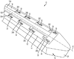
図1は、微小加工CED装置10の例示的な一実施形態を示す。装置10は、概して、1つまたは複数のシャンク部分14が連結される、支持足場12を含む。シャンク部分14は、その上またはその中に形成された1つまたは複数の流体送達導管16を含み得る。
FIG. 1 shows an exemplary embodiment of a
例示された支持足場12は、概して、近位端部18、遠位端部20、および近位端部18と遠位端部20との間に延びる長さ方向軸22を有する細長い本体により形成される。長さ方向軸22に垂直な面で取った、例示された足場12の断面は、実質的に矩形の形状を有するが、円形、六角形、および楕円を含む、様々な断面形状のうち任意のものを使用してよい。足場12は、装置10に構造的剛性を与えて、標的組織への挿入を容易にし得る。組織貫通およびナビゲーションを助けるため、支持足場12の遠位端部20は、テーパー状になり、先がとがり、かつ/または鋭利にされることができる。例示された実施形態では、足場12は、丸い非外傷性先端部を備えて、組織に対し外傷を引き起こさずに、組織を通じた挿入を容易にする。
The illustrated
支持足場12は、剛性または半剛性であってよく、分解可能な熱可塑性ポリマー、例えば、分解可能な熱可塑性ポリエステルまたは分解可能な熱可塑性ポリカーボネートから形成され得る。一実施形態では、支持足場12は、ポリ(乳酸‐co‐グリコール酸)(PLGA)から形成され、標的組織内で生分解するように構成される。これにより、有利なことには、装置10が標的組織内にいったん位置付けられれば支持足場12を取り外す必要がなくなり、そのため、流体送達導管16の位置付けを妨害する可能性が回避される。当技術分野で既知のシリコンまたは様々なセラミックス、金属、およびプラスチックを含む、様々な他の材料のいずれかを使用して、支持足場12を形成することもできる。
The
支持足場12は、ある量の薬剤を含有してよく、または、ある量の薬剤を含浸してよい。あるいは、またはさらに、支持足場12の表面が薬剤でコーティングされてよい。例示的な薬剤は、抗炎症性成分、薬剤透過性増大成分、遅延放出性コーティングなどを含む。一実施形態では、足場12は、注入部位周囲での膨張、およびそのような膨張により生じ得る流体送達パターンの中断を防ぐことのできる、デキサメタゾンなどのコルチコステロイドでコーティングされるか、またはコルチコステロイドを含浸することができる。
The
足場12は、約100μm〜約200μmの幅を有してよく、標的組織に応じて(例えば標的組織が位置する深さに応じて)変化する長さを有してよい。一実施形態では、足場12は、2cm〜3cmの長さである。
足場12はまた、装置10のシャンク部分14を保持するか、またはこれと噛み合うように構成された、凹部または棚部分24を含み得る。加えて、以下でさらに説明するように、足場12は、複数のシャンク部分14に連結される、複数の凹部または棚部分を含み得る。この場合、凹部または棚部分は、足場の複数の異なる表面上に形成され得る。水滴からの表面張力、接着剤、および/または生体適合性ワセリンなど、様々な技術を使用して、シャンク部分14を支持足場12に連結することができる。
装置10は、支持足場12に噛み合うことができる、1つまたは複数のシャンク部分14も含み得る。シャンク部分14は、1つまたは複数の流体送達導管16が内部または上に形成された、可撓性基板であってよい。シャンク部分14は、シリコンまたはパリレンなど、様々な材料のうちのいずれかから形成され得る。
The
1つまたは複数の流体送達導管16は、装置のシャンク部分14内または上に形成され得る。導管16は、足場12の長さ方向軸22に概ね平行な方向に、シャンク部分14の表面に沿って延びてよく、長さ方向軸22と非ゼロ角度を形成する方向に延びる、1つまたは複数の側方部分26を有し得る。
One or more
各導管16は、流体入口ポート(図1には不図示)、および1つまたは複数の流体出口ポート28を含み得る。流体入口ポートは、装置10の近位端部に位置付けられてよく、例えば1つまたは複数のポンプ、計器、弁、または他の適切な制御装置によって、導管16を流体貯蔵部と流体連通させることができる。このような制御装置は、流体が装置10に供給される圧力、または装置10に供給される流体の速度もしくは体積を調整するのに使用され得る。
Each
流体入口ポートを通して導管16に供給される流体は、導管の内側内腔を通って方向付けられ、1つまたは複数の流体出口ポート28を通って放出される。流体出口ポート28は、流体の様々な放出パラメータを制御するようにサイズ決めされ、成形され、かつ/または位置付けられることができる。例えば、流体出口ポート28は、流体が装置10から放出される方向、標的組織内での流体の分布、および、流体が放出される速度もしくは圧力を制御するように構成され得る。
Fluid supplied to the
例示された実施形態では、シャンク部分14は、その中を通って延びる第1および第2のパリレン導管16A、16Bを含む。導管16A、16Bは、長さ方向部分と、流体出口ポート28が形成される複数の側方延長部26と、を含む。流体出口ポート28のサイズは、装置10の遠位端部20に向かって次第に増大し、これにより、有利なことには、装置の長さに沿って生じる圧力損失を相殺でき、流体が複数の流体出口ポート28のそれぞれから実質的に同じ圧力で放出される。例示された流体出口ポート28は、流体の放出方向を制御するようにも成形される。ポート28Aおよび28Cは、横または側方に開口しているが、ポート28Bおよび28Dは、装置10の上部に向かって開口している。
In the illustrated embodiment, the
装置はまた、シャンク部分14内もしくは上、または足場12上に据え付けられた、1つまたは複数のセンサー30を含み得る。センサー30は、温度センサー、pHセンサー、圧力センサー、酸素センサー、張力センサー、問い合わせ可能センサー、グルタミン酸塩センサー、イオン濃度センサー、二酸化炭素センサー、乳酸塩センサー、神経伝達物質センサー、または様々な他のセンサータイプのいずれかを含んでよく、制御回路にフィードバックを与えることができ、制御回路は、感知された1つまたは複数のパラメータに基づいて、装置10を通る流体の送達を調整することができる。1つまたは複数の電極32が、シャンク部分14または支持足場12の中または上に設けられてもよく、この電極は、標的組織に電気エネルギーを送達するため、例えば標的組織を刺激するか、または標的組織を焼灼するために使用されることができる。一実施形態では、電気エネルギーは、電極32を通って送達され、薬剤が同時に、流体送達導管16を通って送達される。
The device may also include one or
装置10は、ヒトまたは動物の身体の脳、耳、他の神経組織、または他の部分の疾患を治療するために薬剤のCEDに使用され得る。脳で使用されると、装置10は、正圧下で薬剤を組織内に直接注入することにより、血液脳関門(BBB)を迂回することができる。装置10は、1)CEDで使用される従来の針と比べて断面積が小さい;2)従来の針と比べて、脳に挿入された際の組織に対する妨害が少ない;3)挿入された部分の外側に沿った逆流または還流が排除され、これにより、従来の針に比べ、装置10内の薬剤送達の速度が速くなる;4)脳内への挿入中に、流体送達導管16の閉塞が最小化されるか、またはまったく起こらない;5)複数のパリレン導管16がシリコンシャンク14内に作製されることができ、それぞれが別々の流体(薬剤)を導き、これにより複数の物質の同時送達、連続送達、またはプログラムされた送達が可能となる;6)装置10が、薬剤送達システムとして、また、圧力、pH、イオン特異的濃度(ion-specific concentrations)、場所、および他のパラメータなどであるがこれらに限定されない、局所的組織特徴を測定するセンサー装備プローブとして、同時に機能する可能性を有する;7)装置10が、薬剤放出パターンの方向制御を可能にする、など、いくつかの利点を提供する。
The
装置10は、装置の流体送達導管16の流体入口ポートへの流体取り付け(fluid attachment)が内部または表面で行われ得るカニューレまたは針など、長く薄い挿入用輸送手段(insertion vehicle)の遠位端部に機能的に取り付けられ得る。これは、比較的厚い組織の貫通、例えばヒトの頭蓋を通した挿入、を伴う適用において、特に有利となり得る。
The
薬剤含有流体の送達に加え、装置10はまた、組織透過性を改変し、標的組織における薬剤分布を改善するために、酵素または他の材料を送達するのに使用されてもよい。例えば、脳組織内への薬剤含有ナノ粒子の浸透は、少なくとも1つの脳細胞外基質成分の酵素消化、および脳組織内へのナノ粒子の頭蓋内注入により高められ得る。別の実施形態では、少なくとも1つの酵素は、酵素消化工程中にナノ粒子の表面に固定され得る。装置10は、異なる送達装置を使用する必要なしに、また、潜在的合併症を伴わずに、事実上任意の順序、順序付け(sequencing)、および/またはタイミングで、例えば薬剤送達部位を変え得る酵素物質および/または他の物質、ならびに治療物質を送達する能力を提供することができる。
In addition to delivering drug-containing fluids, the
装置10は、例えば、スタイレットまたは把持ツールを、導管16のうちの1つを通して標的部位まで通過させて、その後、スタイレットまたは把持ツールを、生検標本が入った状態で、標的部位から引き抜くことにより、組織に生検を実施するのに使用されることもできる。いくつかの実施形態では、シャンク部分14または支持足場12は、生検目的で、内部を通って延びる、より大きい直径の内腔を有してよく、より小さい流体導管16が、その外側に形成されている。
The
図2Aおよび図2Bは、微小加工CED装置110の別の例示的な実施形態を示す。装置110は、矩形の支持足場112を含み、シャンク部分114および付随の流体送達導管116が、足場の4つの側面それぞれに連結されている。図2Bの断面図に示すように、シャンク部分114は、支持足場112の側壁に形成された、対応する凹部124内部に配される。代替的実施形態では、シャンク部分114は、足場112上に表面据え付けされ(surface mounted)得る。足場112の4つの側面それぞれに、シャンク部分114および流体送達導管116を位置付けることは、装置110からの薬剤含有流体の360°の対流をさらに促進し得る。
2A and 2B show another exemplary embodiment of a
装置110の構造および機能は、他の点では、前述した装置10と実質的に同じであり、そのため、それに関するさらなる説明は、簡潔にするため省略する。
The structure and function of the
図3Aおよび図3Bは、微小加工CED装置210の別の例示的な実施形態を示す。装置210は、円筒形支持足場212を含み、シャンク部分214および付随の流体送達導管216が、足場212の外面の周りに離間関係で連結されている。図3Bの断面図に示すように、シャンク部分214は、支持足場212の側壁に形成された、対応する凹部224内部に配される。代替的実施形態では、シャンク部分214は、足場212上に表面据え付けされ得る。シャンク部分214および流体送達導管216の可撓性の性質により、それらが湾曲するか、または別様に、足場212の表面外形に適合するような輪郭にされることができるのが、理解されるであろう。図示のようにシャンク部分214および流体送達導管216を足場212の外面の周りに位置付けることは、装置からの薬剤含有流体の360°の対流をさらに促進し得る。
3A and 3B illustrate another exemplary embodiment of a
装置210の構造および機能は、他の点では、前述した装置10と実質的に同じであり、そのため、それに関するさらなる説明は、簡潔にするため省略する。
The structure and function of the
図4は、薬剤送達システム300の概略図であり、このシステムは、前述した装置10、110、210のうちのいずれであってもよいマイクロカテーテルCED装置310を含む。システム300は、制御弁306を介してポンプ304に連結された、薬剤含有流体の貯蔵部302を含む。制御弁が開かれると、貯蔵部302内の流体は、ポンプ304による圧力下で、圧力調整器308に供給され、圧力調整器は、流体がカテーテル310に供給される圧力を調節することができる。制御弁306、ポンプ304、および調整器308は、コントローラ301に動作可能に連結されてよく、コントローラは、マイクロプロセッサおよびメモリを含むことができ、また、非一時的コンピュータ可読記憶媒体に保存された薬剤送達制御プログラムを実行するように構成され得る。コントローラ301は、弁306を開閉し、ポンプ304をオンまたはオフにし、ポンプ304の出力圧力を変化させ、かつ/あるいは調整器308の圧力設定点を調節するように、構成され得る。コントローラ301はまた、カテーテル310内または上に据え付けられた1つまたは複数のセンサー330を含むフィードバックループを介して、感知されたパラメータを示す情報を受信することもできる。したがって、カテーテル310に植え込まれた1つまたは複数のセンサー330からのフィードバックに応答して、コントローラ301は、カテーテル310への流体の流れを開始または停止させ、流体がカテーテル310に供給される圧力を増大または減少させることなどを、行うことができる。一実施形態では、カテーテル310は、カテーテル310付近で流体圧力を測定する圧力センサー330を含み、コントローラ301は、圧力センサー330からのフィードバックに基づいて、流体供給圧力を、実質的に一定のレベルに保つように構成される。
FIG. 4 is a schematic diagram of a
図5Aおよび図5Bは、本明細書に記載する装置と共に使用され得る流体送達導管の代替的実施形態を示す。図5Aでは、流体送達導管416は、単一の下流内腔438へとまとまる第1および第2の上流内腔434、436を含む。組み合わせられた内腔434、436の内側寸法は、合流部(merge)において徐々に減少し、これにより、有利なことに、下流内腔428を通って流れる流体の速度が増大し得る。例示された実施形態では、下流内腔438の断面積は、第1の上流内腔434の断面積より小さく、また、第2の上流内腔436の断面積より小さく、流量制限部が送達導管416内に形成される。
FIGS. 5A and 5B illustrate an alternative embodiment of a fluid delivery conduit that may be used with the devices described herein. In FIG. 5A,
好ましくは、下流内腔438により形成された狭窄領域は、送達導管416の近位隣接部分の断面積より約20%小さい断面積を有する。さらに好ましくは、狭窄領域は、送達導管の近位隣接部分の断面積より約30%小さい断面積を有する。さらにいっそう好ましくは、狭窄領域は、送達導管の近位隣接部分の断面積より約40%小さい断面積を有する。
Preferably, the constricted region formed by the
一実施形態では、近位隣接部分は、約1μm〜約50μmの高さを有し、狭窄領域は、約1μm〜約25μmの高さを有する。別の実施形態では、近位隣接部分は、約10μm〜約100μmの幅を有し、狭窄領域は、約5μm〜約50μmの幅を有する。 In one embodiment, the proximal adjacent portion has a height of about 1 μm to about 50 μm and the constricted region has a height of about 1 μm to about 25 μm. In another embodiment, the proximal adjacent portion has a width of about 10 μm to about 100 μm, and the constricted region has a width of about 5 μm to about 50 μm.
前述した、この「減少の利点(step-down advantage)」は、装置の送達プロファイルを調整するための追加の圧力および速度制御をもたらす。図5Bに示すように、複数の出口ポート428は、第1および第2の上流内腔434、436と流体連通し、かつ/または下流内腔438と流体連通して、配され得る。
This “step-down advantage”, described above, provides additional pressure and rate control to adjust the delivery profile of the device. As shown in FIG. 5B, a plurality of
図6は、分解可能足場512の単一の表面上に据え付けられた単一の流体送達導管516を有する微小加工CED装置510の例示的な一実施形態の電子顕微鏡写真である。図示のとおり、流体送達導管516は、約25μmの幅であり、流体出口ポート528は、縦方向に約500μm離間している。
FIG. 6 is an electron micrograph of an exemplary embodiment of a
本明細書に開示する装置は、正圧下で薬剤含有流体を標的組織領域に送達するのに用いられ得る。図7は、患者の脳40内の標的組織に対する薬剤の対流強化送達を行うための1つの例示的な方法を示す。適切な部位の準備および洗浄の後で、組織開口部が、患者の頭皮および頭蓋44を通して形成されて、脳40を露出させることができる。組織開口部を形成する前または後で、台座46が、エポキシまたは他の接着剤48を用いて、図示のようにオプションとして患者に据え付けられ得る。台座46は、CED装置10が挿入される間CED装置10を支持することができ、また、長期植え込みに特に有用となり得る。
The devices disclosed herein can be used to deliver a drug-containing fluid to a target tissue region under positive pressure. FIG. 7 illustrates one exemplary method for performing convection enhanced delivery of a drug to a target tissue within a patient's
CED装置10は、図8に示すように、オプションとして、CED装置10と噛み合うための微小加工境界面を備えたカニューレ50に連結され得る。誘導手術において定位フレーム(stereotactic frame)に結合するように構成された標準的カニューレを含む、様々なカニューレのうち任意のものを使用することができる。いくつかの実施形態では、カニューレは、長時間(例えば、30日)の植え込みに適した可撓性カテーテルを含み得る。このカテーテルは、約15cmの長さで、約2cmの直径であってよい。カニューレは、約1.83m(約6フィート)の長さであり、近位端部に流体とバイオセンサーとの境界面用のコネクタを備えた、チューブ部分を含み得る。
The
図7を再び参照すると、CED装置10は、組織開口部を通って脳40内に進められ得る。前述したとおり、CED装置10の足場12は、剛性であってよく、標的領域に向かって脳組織を通る貫通を促進するために先がとがるかまたは鋭利な先端部20を含み得る。1つまたは複数の放射線不透過性マーカーが、CED装置10に含まれて、X線撮像を可能にすることができる(例えば、標的組織内部またはその付近でのCED装置10の適切な設置を確認する)。分解可能足場12が使用される実施形態では、足場12は、挿入直後に分解して、可撓性シャンク部分14およびその上に据え付けられた流体送達導管16のみを残し得る。シャンク14の可撓性の性質により、脳40が頭蓋44内で(例えば、矢印52の方向に)移動した場合にCED装置10が脳40と共に動くことができ、これにより、別の状況では剛性装置で生じるかもしれない、CED装置10に隣接した脳組織の局所変形が妨げられる。このような変形は、装置の表面に沿った加圧流体の逆流を生じる場合があり、これにより、望ましくないことには、流体が標的組織に到達するのが妨げられる。
Referring again to FIG. 7, the
いったんCED装置10が標的組織内部または標的組織に隣接して位置付けられると、注入媒質(例えば薬剤含有流体)が、正圧下で、装置10の1つまたは複数の流体送達導管16の1つまたは複数の流体入口ポートを通してCED装置10に供給され得る。図9に示すように、注入媒質は、対象組織領域において装置10の流体送達導管の流体出口ポートから、圧力下で排出される。送達プロファイル54は、出口ポートサイズ、出口ポート形状、送達導管サイズ、送達導管形状、流体供給圧力、流体速度などといったパラメータを変化させることにより、調節され得る。
Once the
薬剤送達は、CED装置を戦略的に位置付けることによって、かつ/または複数のCED装置を使用することによって、さらに強化され得る。例えば、図10に示すように、複数のCEDプローブ10A、10B、10C、10Dが、標的部位56(例えば、腫瘍)の周りに離間関係で位置付けられてよく、複数のCED装置のそれぞれに形成された1つまたは複数の流体出口ポートは、標的部位と整列する。この実施例では、指向性流体放出のためにサイズ決めされ位置付けられた流体出口ポートを有するCED装置は、放出の方向が標的組織に向けられるように(例えばX線写真の補助により)方向付けられ得る。1つまたは複数の薬剤含有流体は、次に、正圧下で複数のCED装置から標的部位に送達され得、薬剤は、標的部位を実質的に取り囲み、標的部位に浸み込むか、あるいは、標的部位のいくつかの側に送達される。流体が供給される圧力、または様々な他の送達パラメータのうちのいずれかは、例えばCED装置上に配された1つまたは複数のマイクロセンサーからのフィードバックに基づいて、複数のCED装置それぞれで独立して制御され得る。例えば、4つのCED装置が標的部位を取り囲むように植え込まれた、例示される実施形態では、コントローラは、CED装置に固定された圧力センサーからのフィードバックに基づいて、4つのCED装置それぞれについて流体圧力を増減させるように構成され得、4つのCED装置それぞれの放出圧力は、実質的に同じレベルで維持される。 Drug delivery can be further enhanced by strategically positioning the CED device and / or by using multiple CED devices. For example, as shown in FIG. 10, a plurality of CED probes 10A, 10B, 10C, 10D may be positioned in a spaced relationship around a target site 56 (eg, a tumor) and formed in each of a plurality of CED devices. The one or more fluid outlet ports are aligned with the target site. In this embodiment, a CED device having a fluid outlet port sized and positioned for directional fluid ejection is oriented (eg, with the aid of a radiograph) such that the direction of ejection is directed to the target tissue. obtain. The one or more drug-containing fluids can then be delivered from a plurality of CED devices to the target site under positive pressure so that the drug substantially surrounds and penetrates the target site or Delivered to several sides of the site. Any of the pressure at which the fluid is delivered, or various other delivery parameters, is independent for each of the plurality of CED devices, eg, based on feedback from one or more microsensors disposed on the CED device. Can be controlled. For example, in the illustrated embodiment in which four CED devices are implanted to surround the target site, the controller may fluid for each of the four CED devices based on feedback from a pressure sensor secured to the CED device. It can be configured to increase or decrease the pressure, and the discharge pressure of each of the four CED devices is maintained at substantially the same level.
複数のCED装置は、1つの組織開口部を通して挿入されてよく、あるいは、複数の別個の組織開口部が、複数のCED装置の挿入を容易にするように形成され得る。 Multiple CED devices may be inserted through one tissue opening, or multiple separate tissue openings may be formed to facilitate insertion of multiple CED devices.
図11に示すように、複数の流体送達導管を有するCED装置は、有利なことに、薬剤含有流体と共に1つまたは複数の共同因子を送達するのに用いられ得る。例えば、抗炎症薬、酵素、および様々な他の機能的物質が、一次導管16Aを通した薬剤含有流体の送達前、送達中、または送達後に、二次導管16Bを通して送達され得る。追加の流体送達導管も、感知またはモニタリングに使用され得る。
As shown in FIG. 11, a CED device having multiple fluid delivery conduits can be advantageously used to deliver one or more cofactors with a drug-containing fluid. For example, anti-inflammatory drugs, enzymes, and various other functional substances can be delivered through the
本明細書に開示する方法および装置が、患者体内の標的組織に直接、機能的物質の対流強化送達をもたらし得ることが、前述した内容から理解されるであろう。この対流強化送達は、広範囲の疾患、病状、外傷、病気などの治療に使用され得る。 It will be appreciated from the foregoing that the methods and devices disclosed herein can provide convective enhanced delivery of functional substances directly to a target tissue within a patient. This convection-enhanced delivery can be used for the treatment of a wide range of diseases, medical conditions, trauma, illnesses and the like.
例えば、中枢神経系(CNS)新生物は、抗体(例えば、抗上皮増殖因子(EGF)受容体モノクローナル抗体)または核酸構造物(例えば、リボ核酸干渉(RNAi)物質、アンチセンスオリゴヌクレオチド、もしくはアデノウィルス、アデノ随伴ウィルスベクター、もしくは他のウィルスベクター)を、罹患組織に送達することにより治療され得る。 For example, central nervous system (CNS) neoplasms can be antibodies (eg, anti-epidermal growth factor (EGF) receptor monoclonal antibodies) or nucleic acid constructs (eg, ribonucleic acid interference (RNAi) substances, antisense oligonucleotides, or adenoviruses). , Adeno-associated virus vectors, or other viral vectors) can be treated by delivering them to affected tissues.
別の例示的な実施形態では、てんかんが、脳内の標的領域に鎮痙剤を送達することにより治療され得る。別の実施形態では、パーキンソン病が、グリア細胞由来神経栄養因子(GDNF)などのたんぱく質を送達することにより治療され得る。さらなる実施形態では、ハンチントン病が、リボ核酸干渉(RNAi)物質またはアンチセンスオリゴヌクレオチドなどの核酸構造物を送達することにより治療され得る。 In another exemplary embodiment, epilepsy can be treated by delivering an antispasmodic agent to a target area in the brain. In another embodiment, Parkinson's disease can be treated by delivering a protein such as glial cell derived neurotrophic factor (GDNF). In further embodiments, Huntington's disease can be treated by delivering nucleic acid constructs such as ribonucleic acid interference (RNAi) agents or antisense oligonucleotides.
本明細書に開示される方法および装置は、卒中を治療するためにニューロトロフィンを正圧下で送達するため、かつ/またはリソソーム蓄積症を治療するためにリソソーム酵素などのたんぱく質を送達するため、使用されることもできる。 The methods and devices disclosed herein deliver neurotrophins under positive pressure to treat strokes and / or deliver proteins such as lysosomal enzymes to treat lysosomal storage diseases, It can also be used.
別の実施形態では、開示された方法および装置は、抗アミロイドおよび/または神経成長因子(NGF)を正圧下で送達することにより、アルツハイマー病を治療するのに使用され得る。さらなる実施形態では、筋萎縮性側索硬化症は、脳由来神経栄養因子(BDNF)または毛様体神経栄養因子(CNTF)などのたんぱく質を、正圧下で脳、脊柱管、または中枢神経系内の他の部分に送達することにより治療され得る。慢性脳損傷は、本明細書に開示される方法および装置に従って、脳由来神経栄養因子(BDNF)および/または線維芽細胞増殖因子(FGF)などのたんぱく質を、正圧下で送達することにより治療され得る。 In another embodiment, the disclosed methods and devices can be used to treat Alzheimer's disease by delivering anti-amyloid and / or nerve growth factor (NGF) under positive pressure. In a further embodiment, amyotrophic lateral sclerosis causes proteins such as brain-derived neurotrophic factor (BDNF) or ciliary neurotrophic factor (CNTF) to enter the brain, spinal canal, or central nervous system under positive pressure. Can be treated by delivery to other parts. Chronic brain injury is treated by delivering proteins such as brain-derived neurotrophic factor (BDNF) and / or fibroblast growth factor (FGF) under positive pressure according to the methods and devices disclosed herein. obtain.
本明細書に開示される装置および様々な関連治療方法の使用が、患者の脳に限定されないことが理解されるであろう。むしろ、これらの方法および装置は、脊髄を含む、患者の身体の任意の部分に薬剤を送達するために使用され得る。 It will be appreciated that the use of the devices disclosed herein and various related treatment methods is not limited to the patient's brain. Rather, these methods and devices can be used to deliver drugs to any part of a patient's body, including the spinal cord.
図12に示すように、CED装置10は、患者の脊柱管60内部の標的領域への治療薬の送達を容易にするように、患者の椎骨58に隣接して形成された組織開口部を通して挿入され得る。薬剤含有流体を脊柱管に送達する従来の方法では、流体が患者の脳脊髄液(CSF)と混ざり、これにより、薬剤が標的組織から離れて運ばれてしまい、薬剤が患者の非標的エリアにおいて作用すると合併症を引き起こす場合がある。一方、本明細書に開示された最小サイズのCED装置は、高流速の薬剤含有流体と相まって、薬剤送達の極めて正確な標的化を可能にし、患者の脳脊髄液(CSF)中への送達を回避することができると共に、脊柱管の特定の標的領域内への送達は依然として可能にする。一実施形態では、幹細胞が、例えばALSを治療するために、脊柱管または中枢神経系内の他の部分内に送達され得る。
As shown in FIG. 12, the
本明細書に開示される方法および装置は、薬剤含有流体を直接患者の耳の一部内に注入することにより、平衡障害または聴覚障害を治療するために使用されることもできる。薬剤を内耳に送達する既存の技術では、外耳62および外耳道64を通って入ることが必要とされ、これにより、耳の繊細な構造が損傷される場合がある。本実施形態では、図13〜図14に示すように、代わりに、組織開口部が、患者の耳66の後ろで頭蓋44に形成されて、CED装置10の挿入を可能にすることができる。装置10は、組織開口部を通して、患者の耳の標的部分(例えば、内耳68、蝸牛70、コルチ器官、および/または基底膜)内に挿入され得る。次に、薬剤含有流体が、装置10を通して、正圧下で耳の標的部分へと送達され得る。ヒト無調遺伝子を含む、さまざまな薬剤のうち任意のものを使用して、耳を治療することができる。
The methods and devices disclosed herein can also be used to treat balance disorders or hearing disorders by injecting a drug-containing fluid directly into a portion of a patient's ear. Existing techniques for delivering drugs to the inner ear require entry through the
図15に示すように、本明細書に開示される方法および装置は、薬剤含有流体を大脳皮質へ送達することにより、アルツハイマー病または他の神経学的状態を治療するのに使用され得る。薬剤含有流体は、個々にまたは一緒に、かつ同時にまたは連続的に、脳の様々な領域のいずれかに送達され得る。これらの領域は、聴覚皮質、下部側頭葉、前頭前皮質、運動前野、一次運動野、補充運動皮質、体性感覚皮質、頭頂葉皮質、視覚野、味覚野などを含み得る。 As shown in FIG. 15, the methods and devices disclosed herein can be used to treat Alzheimer's disease or other neurological conditions by delivering drug-containing fluids to the cerebral cortex. Drug-containing fluids can be delivered to any of the various regions of the brain, individually or together and simultaneously or sequentially. These regions may include auditory cortex, inferior temporal lobe, prefrontal cortex, premotor cortex, primary motor cortex, supplementary motor cortex, somatosensory cortex, parietal cortex, visual cortex, gustatory cortex and the like.
図16に示すように、本明細書に開示される方法および装置は、胎児、または体内に胎児がいる患者に治療用物質(例えば幹細胞)を送達するのにも使用され得る。これは、胎児手術中に治療用物質を送達するのに特に有利となり得る。図示のとおり、微小流体CED装置は、薬剤含有流体を、臍帯、臍動脈、臍静脈、胎盤、および/または子宮壁に送達するのに使用され得る。 As shown in FIG. 16, the methods and devices disclosed herein can also be used to deliver therapeutic substances (eg, stem cells) to a fetus or a patient who has a fetus in the body. This can be particularly advantageous for delivering therapeutic substances during fetal surgery. As shown, the microfluidic CED device can be used to deliver a drug-containing fluid to the umbilical cord, umbilical artery, umbilical vein, placenta, and / or uterine wall.
図17Aは、支持足場612、少なくとも1つのシャンク614、および少なくとも第1および第2の流体送達導管616A、616Bを含む、微小流体CED装置610の別の例示的な実施形態を示す。流体送達導管616A、616Bは異なる長さを有し、流体送達導管の出口ポート628A、628Bは、シャンク614に沿って長さ方向にずれている。言い換えれば、第1および第2の流体送達導管616A、616Bは、互いから距離D離れたところで終端しており、それらの出口ポート628A、628Bは、長さ方向にずれる。例示的な実施形態では、距離Dは、約0.02μm〜約100mm、好ましくは約0.1μm〜約10mmである。装置610は、前記のとおり、1つまたは複数のセンサー630および/または電極632も含み得る。装置610の構造および機能は、他の点では、前述した装置10と実質的に同じであるので、それらに関するさらなる説明は、簡潔にするため省略する。
FIG. 17A illustrates another exemplary embodiment of a
使用中、装置610は、標的領域(例えば、患者の中枢神経系の海綿状奇形)内に挿入され得、第2の流体送達導管616Bの出口ポート628Bが、標的領域の中央部分(例えば、海綿状奇形の中心部)内部に配され、第1の流体送達導管616Aの出口ポート628Aは、標的領域の周辺部分(例えば、海綿状奇形の外面)内部に配される。したがって、標的領域は、内側から外へ(from the inside-out)かつ外側から中へ(from the outside-in)治療され得る。海綿状奇形の場合、装置610により、薬剤は、海綿状奇形の中心部内、ならびに血管型細胞(vascular-type cells)が増殖している海綿状奇形の表面に送達されることができる。
In use, the
図17Bは、微小流体CED装置710の別の例示的な実施形態を示す。装置710は、膨張可能部材772(例えば、強化および/または適合バルーン)が装置710に含まれることを除いて、図17Aの装置610と実質的に同一である。膨張可能部材772は、第1の流体送達導管716Aと流体連通していてよく、流体は、第1の流体送達導管716Aを通して供給されて、膨張可能部材772を膨張させ、膨張可能部材772の体積を増大させるか、または、膨張可能部材772内部の圧力を増大させることができる。同様に、流体は、第1の流体送達導管716Aを介して膨張可能部材772から引き出されて、膨張可能部材772の体積を低減するか、または、膨張可能部材内部の圧力を低減することができる。膨張可能部材772は、(例えば、装置710の一部を実質的に取り囲むように)装置710の外部に連結されてよく、または、装置710に形成された凹部内から展開するように構成され得る。装置710の構造および機能は、他の点では、前述した装置10と実質的に同じであり、このため、それらに関するさらなる説明は、簡潔にするため省略する。
FIG. 17B shows another exemplary embodiment of a
図18A〜図18Bに示すように、本明細書に開示される方法および装置は、例えば1つまたは複数の薬剤を海綿状奇形に送達することにより、海綿状奇形を治療するのに使用され得る。図18Aを参照すると、CED装置、例えば前述した装置710は、海綿状奇形74に挿入され得、第1の流体送達導管716Aの出口ポート728Aおよび第2の流体送達導管716Bの出口ポート728Bは双方、海綿状奇形74内に配される。次に、1つまたは複数の血管形成抑制因子などの薬剤を含有する流体は、第2の流体送達導管716Bを通して海綿状奇形74の内部に供給され得る。同時に、またはその直後に、流体は、図18Bに示すように、第1の流体送達導管716Aを通して供給されて、膨張可能部材772を膨張させ、かつ/または、膨張可能部材772内の圧力を増大させる。膨張可能部材772が海綿状奇形74内部で膨張すると、かつ/または圧力が膨張可能部材772内部で増大すると、圧縮力が、海綿状奇形74内に先に放出された薬剤含有流体に及ぼされ、流体を周囲組織内に押し込む。
As shown in FIGS. 18A-18B, the methods and devices disclosed herein can be used to treat a spongy malformation, for example, by delivering one or more agents to the spongy malformation. . Referring to FIG. 18A, a CED device, such as the
本明細書に開示される微小流体CED装置は、様々な技術のうち任意のものを使用して製造され得る。例えば、装置は、シリコン基板を微小加工し、次に、仕上げた部品を、1つまたは複数の微小毛細管を含むカテーテル部分に連結することにより、製造され得る。いくつかの実施形態では、リトグラフ微小加工プロセス(lithographic microfabrication process)を使用して、CED装置を製造することができる。このプロセスは、(1)シリコン基板をバックエッチング(back etching)して、シャンクおよび尾部の深さを形成すること、(2)ポリイミドをシリコン基板の上側でスピンコーティングすること、(3)犠牲レジストをスピンコーティングして、マイクロチャネルを画定すること、(4)パリレンコーティングをポリイミド層の上側に塗布すること、(5)犠牲レジストを除去するためにアルミニウムマスクを取り付け、これによりパリレンチャネルを形成すること、(6)シリコン基板をフロントエッチング(front etching)して、装置本体を形成すること、を含み得る。他の実施形態では、このプロセスは、(1)シリコン基板をフロントエッチングして、装置本体を形成すること、(2)マスキングせずに、ポリイミドをシリコン基板の両側にスプレーコーティングすること、(3)ポリイミド上に犠牲レジストをスプレーコーティングすること、(4)上側にパリレンコーティングを塗布すること、(5)犠牲レジストを除去するためにアルミニウムマスクを取り付け、これによりパリレンチャネルを形成すること、を含み得る。 The microfluidic CED device disclosed herein can be manufactured using any of a variety of techniques. For example, the device can be manufactured by microfabricating a silicon substrate and then connecting the finished part to a catheter portion that includes one or more microcapillaries. In some embodiments, a lithographic microfabrication process can be used to manufacture a CED device. This process consists of (1) back etching the silicon substrate to form a shank and tail depth, (2) spin-coating polyimide over the silicon substrate, and (3) sacrificial resist. Spin coating to define microchannels, (4) applying a parylene coating on top of the polyimide layer, (5) attaching an aluminum mask to remove the sacrificial resist, thereby forming a parylene channel (6) front etching the silicon substrate to form a device body. In other embodiments, the process includes (1) front etching the silicon substrate to form the device body, (2) spray coating polyimide on both sides of the silicon substrate without masking, (3 Including: (4) spray coating a sacrificial resist on the polyimide; (4) applying a parylene coating on the top; (5) attaching an aluminum mask to remove the sacrificial resist, thereby forming a parylene channel. obtain.
図19は、CED装置を製造する例示的な微小加工プロセスを示す。本明細書に開示される様々な方法またはプロセスが、1つまたは複数のフローチャートに関連して図示され得るが、このようなフローチャートまたはその説明により示唆される方法工程のいかなる順序も、それらの工程をその順序で実行することに、方法を制限するものとして解釈されるものではないことに、注意されたい。むしろ、本明細書に開示される方法それぞれの様々な工程は、様々な順番のうちのいずれかで実行されてよい。さらに、例示されたフローチャートは単に例示的な実施形態であるので、例示されたものと比べて、追加工程を含むか、またはより少ない工程を含む、様々な他の方法も、本発明の範囲内である。 FIG. 19 illustrates an exemplary microfabrication process for manufacturing a CED device. Although the various methods or processes disclosed herein may be illustrated in connection with one or more flowcharts, any order of method steps suggested by such flowcharts or descriptions thereof may be considered as those steps. Note that performing the commands in that order is not to be construed as limiting the method. Rather, the various steps of each of the methods disclosed herein may be performed in any of a variety of orders. Furthermore, since the illustrated flowchart is merely an exemplary embodiment, various other methods are also within the scope of the present invention, including additional steps or fewer steps than those illustrated. It is.
工程S800で、洗浄プロセスが、CED装置が製造されるシリコンウェハに対して行われ得る。例えば、高温ナノストリップ洗浄(hot nanostrip clean)が、50℃で30分間行われてよく、その後、脱イオン(「DI」)水でリンスし、例えばVERTEQスピンリンスドライヤーを用いて、スピンリンス乾燥(「SRD」)を行う。他の実施形態では、RCA洗浄が、NH4OH:H2Oを用いて70℃で15分間、その後、HCL:H2Oを用いて70℃で15分間行われ、その後に、DI水リンスおよびSRDが続く。 In step S800, a cleaning process may be performed on the silicon wafer on which the CED device is manufactured. For example, a hot nanostrip clean may be performed at 50 ° C. for 30 minutes, followed by a rinse with deionized (“DI”) water and spin rinse drying (eg, using a VERTEQ spin rinse dryer). “SRD”). In other embodiments, RCA cleaning is performed with NH4OH: H2O at 70 ° C. for 15 minutes, followed by HCL: H 2 O at 70 ° C. for 15 minutes, followed by DI water rinse and SRD.
工程S802で、ウェハは、脱水ベークを受けることができる。いくつかの実施形態では、ウェハは、接触ホットプレート(contact hotplate)を用いて5分間180℃でベークされ得る。ウェハが、以下で論じるプラズマ化学気相堆積(「PECVD」)工程中に400℃まで加熱され得るので、脱水ベークは場合によっては省略されてもよい。したがって、PECVDプロセスの工程時間は、余分な脱水時間に対応するように増大し得る。ホットプレート脱水を省略すると、ホットプレートを先に使用したことにより残される汚染を減少させることもできる。 In step S802, the wafer can undergo a dehydration bake. In some embodiments, the wafer may be baked at 180 ° C. for 5 minutes using a contact hotplate. Since the wafer can be heated to 400 ° C. during the plasma enhanced chemical vapor deposition (“PECVD”) process discussed below, dehydration bake may be optionally omitted. Accordingly, the process time of the PECVD process can be increased to accommodate the extra dewatering time. Omitting hot plate dewatering can also reduce contamination left over by the previous use of the hot plate.
工程S804で、酸化物ハードマスク(oxide hard mark)が、シリコンウェハ上に堆積され得る。いくつかの実施形態では、ハードマスクは、PECVD酸化物沈着により堆積され得(2.5μm、N1.46 酸化物処方(Oxide Recipe))、厚さは、FILMETRICSにより製造されたものなどの測定システムを用いて確認され得る。 In step S804, an oxide hard mark may be deposited on the silicon wafer. In some embodiments, the hard mask can be deposited by PECVD oxide deposition (2.5 μm, N1.46 Oxide Recipe) and the thickness is measured by a measurement system such as that manufactured by FILMETRICS Can be used to confirm.
工程S806では、酸化物ハードマスク902が、例えば図20Aに示すように、シリコンウェハ900上にパターン化され得る。例示的なパターン化プロセスは以下を含む:
高温剥離槽(hot strip bath)でマスクを洗浄(15分、70℃、DIリンスおよびSRDを伴うNMP/TMAH/PG)
レジスト処理(裏側)
蒸気下塗り(Vapor prime)(これは、YIELD ENGINEERING SYSTEMS(「YES」)が製造するものなどのオーブン内で行われてよく、また、ウェットエッチングプロセスに重要となり得る)
レジストをスピン(Spin resist):S1813(4000rpm、1000rpm/秒、30秒)
ソフトベーク:115℃:90秒
残りの裏側レジストのアセトン綿棒での除去
露光:MA6:柔接触(Soft Contact):MASK1=DRIE(深堀り反応性イオンエッチング)(裏側)
PE待機:なし
PEベーク:115℃:60秒
現像(Develop):HAMATECH 726MIF 60秒DP(60secDP)
ハードベーク:115℃:60秒
OXFORD 80エッチャーなどのエッチャー(etcher)を用いたデスカム(酸素プラズマ洗浄、150ワットRF、50sccm O2、約8Pa(60mTorr)、15秒)
緩衝酸化物エッチング(Buffered Oxide Etch)(「BOE」)6:1エッチング:30分、長時間DIリンスおよびSRD
顕微鏡での評価(保存画像による)
酸化物エッチング:OXFORD 80#2(CHF3O2 酸化物エッチング、240ワット、100分(x5 20分サイクル)、50sccm CHF3、2sccm O2、約5.33Pa(40mTorr)、10℃、DCバイアス 119ボルト)
レジスト除去(Strip Resist):OXFORD 80(酸素プラズマ洗浄、150ワットRF、50sccm O2、約8Pa(60mTorr)、10分)
レジスト除去:高温剥離槽(15分 70℃ NMP/TMAH/PG)、DIリンスおよびSRD
レジスト除去:アセトン槽(Acetone Bath)、イソプロピルアルコール(「IPA」)槽、DIリンスおよびSRDを伴うDI水槽
例えば、HAMATECHが製造するホットピラニア洗浄システム(hot piranha cleaning system)を用いたレジスト除去。
In step S806, an oxide
Clean mask in hot strip bath (15 minutes, 70 ° C., NMP / TMAH / PG with DI rinse and SRD)
Resist processing (back side)
Vapor prime (this can be done in an oven, such as that produced by YIELD ENGINEERING SYSTEMS (“YES”), and can be important for wet etching processes)
Spin resist: S1813 (4000 rpm, 1000 rpm / second, 30 seconds)
Soft baking: 115 ° C .: 90 seconds Removal of remaining back side resist with acetone swab Exposure: MA6: Soft Contact: MASK1 = DRIE (deep reactive ion etching) (back side)
PE standby: None PE bake: 115 ° C: 60 seconds Development (Develop): HAMATECH 726MIF 60 seconds DP (60 sec DP)
Hard baking: 115 ° C: 60 seconds
Descum using an etcher such as OXFORD 80 etcher (oxygen plasma cleaning, 150 watt RF, 50
Buffered Oxide Etch (“BOE”) 6: 1 etch: 30 minutes, long DI rinse and SRD
Microscopic evaluation (based on stored images)
Oxide Etching: OXFORD 80 # 2 (CHF3O2 Oxide Etching, 240 Watts, 100 min (
Strip Resist: OXFORD 80 (oxygen plasma cleaning, 150 watt RF, 50 sccm O2, about 8 Pa (60 mTorr), 10 minutes)
Resist removal: High temperature stripping tank (15 min 70 ° C. NMP / TMAH / PG), DI rinse and SRD
Resist removal: acetone bath (Acetone Bath), isopropyl alcohol ("IPA") bath, DI water bath with DI rinse and SRD For example, resist removal using a hot piranha cleaning system manufactured by HAMATECH.
BOEは、等方性である(すなわち、全方向において同じ速度でエッチングする)ので、30分のBOE6:1 エッチングは、全体的に約3μmのアンダーカットを生じ得る。これにより、CADレイアウトのものを超えて、構造の限界寸法が増大し得る。これは、(例えば、その寸法を、実際に所望されるものより3μmだけ小さく作ることにより)CADレイアウトにおいてある程度補われ得る。 Since BOE is isotropic (ie, etches at the same rate in all directions), a 30 minute BOE 6: 1 etch can produce an overall undercut of about 3 μm. This can increase the critical dimension of the structure beyond that of the CAD layout. This can be compensated to some extent in the CAD layout (eg by making its dimensions 3 μm smaller than what is actually desired).
いくつかの実施形態では、酸化物をパターン化するのにウェットBOEを使用する代わりに、CHF3O2反応性イオン「ドライ」エッチングを使用することができる。BOEを使用することの1つの利点は、比較的安価とすることができ(金型費(tool charges)がなく、同時に多くのウェハをエッチングすることができる)、より薄いレジストを使用できる(例えばS1813)ことである。しかしながら、1つの欠点は、寸法が全体的に3μmだけ広がり得ることである。これは、特徴部の臨界サイズが実際に大きい場合には、あまり心配ない(less of a concern)。別の潜在的問題は、BOEが時折、レジスト層の下で毛状であり(このため良好な付着が必要とされる)、エッチングを意図していない領域でエッチングし得ることである。CHF3O2反応性イオンエッチング(「RIE」)では、CADレイアウトでの臨界寸法は、ウェハ上でより確実に再現され得るので、CADにおいて任意の一次サイズ補正(first-order size compensation)を行う必要はない。また、CHF3O2では、より厚いレジスト(SPR220− 4.5)が、2.5μmのPECVD酸化物ハードマスクを通してエッチングするために必要とされ得る。
In some embodiments, instead of using wet BOE to pattern the oxide, a CHF 3
いくつかの実施形態では、レジストは、後に続くボッシュのDRIE(Bosch DRIE)において、初期エッチング工程中に、所定の場所に残され得る。レジスト除去は、最初にO2プラズマ洗浄で、その後に湿式化学剥離液(wet chemical stripper)、さらに、DIリンスおよび乾式N2吹き付け乾燥(dry N2 blow dry)を続けることで、行われ得る。 In some embodiments, the resist may be left in place during the initial etch step in a subsequent Bosch DRIE. Resist removal can be done by first O2 plasma clean, followed by wet chemical stripper, followed by DI rinse and dry N2 blow dry.
工程S808では、例えば図20Bに示すように、シリコンが、酸化物ハードマスク902により画定されたパターンにおいてウェハ900からシリコンを除去するために、深堀り反応性イオンエッチング(「DRIE」)を受けることができる。まず、エッジビード(edge bead)が除去される(レジストが先に除去されていない場合)。次に、UNAXISが製造するものなどのエッチングシステムを用いて、ウェハを通してエッチングし、前側に100μm残すことができる。いくつかの実施形態では、エッチングは、以下のパラメータを使用して行うことができる:
チャンバーシーズン(Chamber Season):x100ループ O型溝(O-Trench)
ウェハエッチング:〜800ループ O型溝(500μmのウェハ内に400μm)
工程1:堆積
RF1 電力:0.1ワット、流量:SF6:2sccm、熱交換1:22℃
RF2 電力:850ワット、流量:C4F8:60sccm、熱交換2:40℃
圧力:約3.2Pa(24mTorr)、流量:Ar:40sccm、He流量:2.76sccm
時間:4.0秒、流量:O2:0sccm、He圧力:約399.97Pa(3.0Torr)
工程2:エッチング1
RF1 電力:8.0ワット、流量:SF6:70sccm、熱交換1:22℃
RF2 電力:850ワット、流量:C4F8:2sccm、熱交換2:40℃
圧力:約3.07Pa(23mTorr)、流量:Ar:40sccm、He 流量:2.76sccm
時間:2.0秒、流量:O2:0sccm、He 圧力:約399.97Pa(3.0Torr)
工程3:エッチング2
RF1 電力:8.0ワット、流量:SF6:100sccm、熱交換1:22℃
RF2 電力:850ワット、流量:C4F8:2sccm、熱交換2:40℃
圧力:約3.2Pa(24mTorr)、流量:Ar:40sccm、He 流量:2.76sccm
時間:6.0秒、流量:O2:0sccm、He 圧力:約399.97Pa(3.0Torr) 4。
In step S808, the silicon is subjected to deep reactive ion etching (“DRIE”) to remove silicon from the
Chamber Season: x100 loop O-Trench
Wafer etching: ~ 800 loop O-groove (400 μm in a 500 μm wafer)
Step 1: Deposition RF1 Power: 0.1 Watt, Flow rate: SF6: 2 sccm, Heat exchange 1: 22 ° C.
RF2 power: 850 watts, flow rate: C4F8: 60sccm, heat exchange 2: 40 ° C
Pressure: about 3.2 Pa (24 mTorr), flow rate: Ar: 40 sccm, He flow rate: 2.76 sccm
Time: 4.0 seconds, flow rate: O2: 0 sccm, He pressure: about 399.97 Pa (3.0 Torr)
Process 2:
RF1 power: 8.0 watts, flow rate: SF6: 70sccm, heat exchange 1: 22 ° C
RF2 power: 850 Watts, flow rate: C4F8: 2sccm, heat exchange 2: 40 ° C
Pressure: about 3.07 Pa (23 mTorr), flow rate: Ar: 40 sccm, He flow rate: 2.76 sccm
Time: 2.0 seconds, flow rate: O2: 0 sccm, He pressure: about 399.97 Pa (3.0 Torr)
Process 3:
RF1 power: 8.0 watts, flow rate: SF6: 100sccm, heat exchange 1: 22 ° C
RF2 power: 850 Watts, flow rate: C4F8: 2sccm, heat exchange 2: 40 ° C
Pressure: about 3.2 Pa (24 mTorr), flow rate: Ar: 40 sccm, He flow rate: 2.76 sccm
Time: 6.0 seconds, flow rate: O2: 0 sccm, He pressure: about 399.97 Pa (3.0 Torr)
いくつかの実施形態では、OERLIKONエッチングが、代わりに行われてよい。いくつかの実施形態では、より薄いウェハ(例えば、約500μmの厚さとは対照的に約300μmの厚さ)を使用して、エッチング時間を低減することができるが、これにより、費用および破損率が増大し得る。このエッチングプロセスの後に、以下が続き得る:
レジスト除去:OXFORD 80(酸素プラズマ洗浄、150ワットRF、50sccm O2、約8Pa(60mTorr)、10分)
レジスト除去:高温剥離槽(15分 70℃ NMP/TMAH/PG)、DIリンスおよびSRD。
In some embodiments, an OERLIKON etch may be performed instead. In some embodiments, thinner wafers (eg, about 300 μm thick as opposed to about 500 μm thick) can be used to reduce etch time, which reduces cost and failure rate. Can increase. This etching process can be followed by:
Resist removal: OXFORD 80 (oxygen plasma cleaning, 150 Watt RF, 50 sccm O2, about 8 Pa (60 mTorr), 10 minutes)
Resist removal: high temperature stripping bath (15 min 70 ° C. NMP / TMAH / PG), DI rinse and SRD.
工程S810では、PECVD酸化物エッチング停止が、例えば図20Cに示すように、ウェハの裏側に対して行われ得る。いくつかの実施形態では、PECVD酸化物904は、例えば前側エッチングが停止されたウェハの裏側上における1.0μmのPECVD酸化物堆積を用いて、工程S808で形成された溝の一番下に堆積され得る。いくつかの実施形態では、シリコン・オン・インシュレーター(「SOI」)ウェハを使用してよく、この場合、SOIウェハ上の埋め込み酸化物(「BOX」)層が、エッチング停止部として作用することができ、PECVD停止層および裏側からのDRIEが不要となる。蒸気フッ化水素(Vapor hydrogen fluoride)(「HF」)が、このような実施形態で使用されて、BOXから最終的な装置を放出することができる。
In step S810, a PECVD oxide etch stop may be performed on the back side of the wafer, for example as shown in FIG. 20C. In some embodiments,
工程S812では、ポリイミド層906が、例えば図20Dに示すように、ウェハ900の前側でパターン化され得る。いくつかの実施形態では、以下のプロセスを使用して、ポリイミド層をパターン化する:
ポリイミドをスピン(4000rpm、500rpm/秒、45秒、〜2μm)。これは、TORAYが製造するPhotoneece PW DC 1000などの、芳香族ポリイミド前駆体溶液を用いて行われ得る。
アセトン綿棒で裏側の残留物を洗浄
ソフトベーク:115℃:3分(接触ポリイミドホットプレート(contact polyimide hot plate))
露光:MA6:柔接触:MASK2=POLY(前側)
PE待機:なし
PEベーク:なし
現像:HAMATECH 726MIF 90秒DP
顕微鏡での評価(保存画像による)
デスカム:OXFORD 80(酸素プラズマ洗浄、150ワットRF、50sccm O2、約8Pa(60mTorr)、15秒)
架橋ポリイミド:処方3:YESのポリイミドオーブン:300+℃
通常プロセス:窒素環境において170℃で30分および320℃で60分。
In step S812, the
Spin polyimide (4000 rpm, 500 rpm / sec, 45 sec, ˜2 μm). This can be done using an aromatic polyimide precursor solution, such as
Clean the backside residue with an acetone swab Soft bake: 115 ° C: 3 minutes (contact polyimide hot plate)
Exposure: MA6: Soft contact: MASK2 = POLY (front side)
PE waiting: None PE baking: None Development: HAMATECH 726MIF 90 seconds DP
Microscopic evaluation (based on stored images)
Descum: OXFORD 80 (oxygen plasma cleaning, 150 watt RF, 50 sccm O2, about 8 Pa (60 mTorr), 15 seconds)
Crosslinked polyimide: prescription 3: YES polyimide oven: 300 + ° C
Normal process: 30 minutes at 170 ° C. and 60 minutes at 320 ° C. in a nitrogen environment.
工程S814では、例えば図20Eに示すように、微小流体チャネルが、犠牲レジスト908を用いて画定され得る。いくつかの実施形態では、以下のプロセスを使用して、微小流体チャネルを画定する:
レジストをスピン:SPR220-7(10μmでは1600rpm、500rpm/秒、45秒)
ソフトベーク1:65℃:1分
ソフトベーク2:90℃:1分
ソフトベーク3:115℃:2分、または
ソフトベーク:90℃、30分(対流式オーブン)
露光:MA6:柔接触:MASK3=チャネル(前側)
PE待機:スタンフォードプロセスを参照
PEベーク:スタンフォードプロセスを参照
現像:HAMATECH 726MIF 120秒DP
顕微鏡での評価(保存画像による)
エッジビードを除去
ハードベーク:115℃:1分
顕微鏡での評価(保存画像による)
デスカム:OXFORD 80(酸素プラズマ洗浄、150ワットRF、50sccm O2、約8Pa(60mTorr)、60秒)
P10 プロフィロメーター評価(チャネルの高さおよび幅を測定)。
In step S814, a microfluidic channel can be defined using a sacrificial resist 908, for example as shown in FIG. 20E. In some embodiments, the following process is used to define the microfluidic channel:
Spin resist: SPR220-7 (1600 rpm, 500 rpm / sec, 45 sec for 10 μm)
Soft baking 1: 65 ° C: 1 minute Soft baking 2: 90 ° C: 1 minute Soft baking 3: 115 ° C: 2 minutes or Soft baking: 90 ° C, 30 minutes (convection oven)
Exposure: MA6: Soft contact: MASK3 = channel (front side)
PE waiting: see Stanford process PE bake: see Stanford process Development: HAMATECH 726MIF 120 seconds DP
Microscopic evaluation (based on stored images)
Remove edge beads Hard bake: 115 ° C: 1 minute Evaluation under microscope (according to stored image)
Descum: OXFORD 80 (oxygen plasma cleaning, 150 watt RF, 50 sccm O2, about 8 Pa (60 mTorr), 60 seconds)
P10 Profilometer evaluation (measures channel height and width).
レジスト層908の厚さにより、微小流体チャネルの高さを決定することができる。同様に、レジスト層908の幅(露光および現像後)により、微小流体チャネルの幅が決まる。レジスト908のクラッキングを避けるため、この工程は、緩やかな増加および減少(slow ramp up and ramp down)で行われ得る。
The thickness of the resist
いくつかの実施形態では、ハードベーク工程中にレジスト908がいくらか逆流することがあり、これにより、レジストは、より良好なアルミニウム適用範囲(better aluminum coverage)のために、傾斜した側壁を有し得る。しかしながら、レジストの逆流は必ずしも必要とは限らず、これは、ウェハがこれらのプロセスの両方でコンフォーマル蒸着(conformal evaporation)またはスパッタ堆積を使用してコーティングされ得、非コンフォーマル蒸着装置に比べて、より多くのウェハを同時にコーティングすることができるためである。 In some embodiments, the resist 908 may have some backflow during the hard bake process so that the resist may have sloped sidewalls for better aluminum coverage. . However, resist backflow is not always necessary, as wafers can be coated using conformal evaporation or sputter deposition in both of these processes, compared to non-conformal deposition equipment. This is because more wafers can be coated simultaneously.
工程S816で、パリレン910の層が、例えば図20Fに示すように、ポリイミド層906および犠牲レジスト908上に堆積される。いくつかの実施形態では、パリレン層910は、約5μmの厚さを有し得る。以下のプロセスが、パリレン堆積のために使用され得る:
レジスト表面を粗面化:OXFORD 80:150ワットRF、50sccm O2、約8Pa(60mTorr)、30秒
パリレンC堆積(3.5g=5μm)。
In step S816, a layer of
Roughened resist surface: OXFORD 80: 150 Watt RF, 50
パリレンは、非常にコンフォーマルな層であってよく、そのため、一部の材料が、各ウェハの裏側にコーティングされ得る。パリレン堆積は、1回に、例えば3つのウェハに対して行われ得る。典型的なパリレン堆積プロセスは、約6時間かかり得る。 Parylene can be a very conformal layer so that some material can be coated on the back side of each wafer. Parylene deposition can be performed at once, eg, on three wafers. A typical parylene deposition process can take about 6 hours.
工程S818では、図20Gに示すように、アルミニウムハードマスク蒸着が行われて、パリレン層910上にアルミニウム層912を付けることができる。以下のプロセスが、アルミニウムハードマスク蒸着のために使用され得る:
パリレン表面を粗面化:OXFORD 80:150ワットRF、50sccm O2、約8Pa(60mTorr)、30秒
蒸着またはスパッタ:アルミニウム:コンフォーマル:150nm(2A/秒)。
In step S818, as shown in FIG. 20G, aluminum hard mask vapor deposition is performed, and an
Roughening the parylene surface: OXFORD 80: 150 Watt RF, 50 sccm O2, about 8 Pa (60 mTorr), 30 seconds Deposition or sputtering: Aluminum: Conformal: 150 nm (2 A / second).
工程S820では、例えば図20Hに示すように、アルミニウムハードマスク912がパターン化され得る。以下のプロセスが、アルミニウムハードマスクをパターン化するのに使用され得る:
液体HMDS下塗り:10秒
レジスト914をスピン:SPR220-7(1600rpm、500rpm/秒、45秒、〜10μm)
ソフトベーク1:65℃:1分
ソフトベーク2:90℃:1分
ソフトベーク3:115℃、または
ソフトベーク:90℃、30分(対流式オーブン)
露光:MA6:柔接触:MASK4=アルミニウム(前側)
PE待機:なし
PEベーク:なし
現像:HAMATECH 726MIF 120秒DP
顕微鏡での評価(保存画像による)
湿式アルミニウムエッチング(5分)−湿式アルミニウムエッチングにより、レジストエッチングマスク914の下を切り取ることができ、CADレイアウトは、これに合わせるように適宜調節され得る。
顕微鏡での評価(保存画像による)
レジスト除去:OXFORD 80(酸素プラズマ洗浄、150ワットRF、50sccm O2、約8Pa(60mTorr)、10分)
レジスト除去:高温剥離槽(15分 70℃ NMP/TMAH/PG)、DIリンスおよびSRD
レジスト除去:アセトン槽、IPA槽、DIリンスおよびSRDを伴うDI水槽
In step S820, an aluminum
Liquid HMDS undercoat: 10 seconds Spin resist 914: SPR220-7 (1600 rpm, 500 rpm / second, 45 seconds, 10 μm)
Soft baking 1: 65 ° C: 1 minute Soft baking 2: 90 ° C: 1 minute Soft baking 3: 115 ° C, or Soft baking: 90 ° C, 30 minutes (convection oven)
Exposure: MA6: Soft contact: MASK4 = Aluminum (front side)
PE waiting: None PE baking: None Development: HAMATECH 726MIF 120 seconds DP
Microscopic evaluation (based on stored images)
Wet aluminum etch (5 minutes) —Wet aluminum etch can cut under the resist
Microscopic evaluation (based on stored images)
Resist removal: OXFORD 80 (oxygen plasma cleaning, 150 Watt RF, 50 sccm O2, about 8 Pa (60 mTorr), 10 minutes)
Resist removal: High temperature stripping tank (15 min 70 ° C. NMP / TMAH / PG), DI rinse and SRD
Resist removal: acetone bath, IPA bath, DI rinse and DI water bath with SRD
前述のプロセスでは、高温剥離槽、アセトン、およびIPAと、選択された特定のポリイミドとの化学的適合性が確認されなければならない。工程S820が終わると、アルミニウム912のストリップが、図20Hのようにハードエッチングマスクとして作用するよう、パリレン層910の上に堆積されている。
In the foregoing process, the chemical compatibility of the high temperature stripping bath, acetone, and IPA with the particular polyimide selected must be confirmed. At the end of step S820, a strip of
工程S822では、周辺のパリレンのエッチ除去(etch removal)が行われ得る。例えば図20Iに示すように、パリレン層910は、ウェハ900の周辺領域916から除去される。以下のプロセスが、パリレンエッチを除去するのに使用され得る:
レジストをスピン:SPR220−7(1000rpm、100rpm/秒、45秒、動的分配(DynamicDispense)、新しいレジスト(FreshResist)、〜12μm)
ソフトベーク:90℃:30分(対流式オーブン)
露光:MA6:柔接触:MASK5=パリレン(前側)
PE待機:スタンフォードプロセスを参照
PEベーク:スタンフォードプロセスを参照
現像:HAMATECH 726MIF 90秒DP
顕微鏡での評価(保存画像による)
ハードベーク:90℃:4〜12時間(対流式オーブンで一晩、緩やかな傾斜(Slow Ramp))
Flood UV露光:ABM:2分
パリレンエッチング:OXFORD 80(前側、酸素プラズマ洗浄、150ワットRF、20〜25分、5μmのパリレン層の完全除去)
パリレンエッチング:OXFORD 80(裏側、酸素プラズマ洗浄、150ワットRF、10〜15分 チップによる)。
In step S822, peripheral parylene can be etched away. For example, as shown in FIG. 20I, the
Spin resist: SPR220-7 (1000 rpm, 100 rpm / second, 45 seconds, DynamicDispense, new resist (FreshResist), ˜12 μm)
Soft baking: 90 ° C: 30 minutes (convection oven)
Exposure: MA6: Soft contact: MASK5 = Parylene (front side)
PE waiting: see Stanford process PE bake: see Stanford process Development: HAMATECH 726MIF 90 seconds DP
Microscopic evaluation (based on stored images)
Hard bake: 90 ° C: 4-12 hours (overnight in convection oven, Slow Ramp)
Flood UV exposure: ABM: 2 minutes Parylene etching: OXFORD 80 (front side, oxygen plasma cleaning, 150 watt RF, 20-25 minutes, complete removal of 5 μm parylene layer)
Parylene etching: OXFORD 80 (back side, oxygen plasma cleaning, 150 watt RF, 10-15 minutes with tip).
ウェハの裏側をエッチングする際、シリコンチップを使用して、ウェハを圧盤(platen)上に吊るすことができ、これにより、ウェハの前側が、こすられたり損傷されたりしない。図20Iは、パリレンエッチ除去後のシステムを示す。図示のとおり、パリレンは、周辺領域において、シリコン表面に至るまでエッチングされ、各装置の周辺部の周りの100μmのシリコンが、ウェハに固定された装置を保持している。パリレンエッチング後、これは、少なくとも4μmのレジストを残すのに役立つことができ、これは、その後、前側において、残りの100μmのシリコンをエッチングするのに使用され得る。したがって、レジスト層は、5μmのパリレンエッチングおよび100μmのシリコンエッチングに適応するように十分厚くされ得る。そうでなければ、新たなレジスト層が適用され得る。 When etching the back side of the wafer, a silicon chip can be used to suspend the wafer on a platen so that the front side of the wafer is not rubbed or damaged. FIG. 20I shows the system after parylene etch removal. As shown, parylene is etched in the peripheral region down to the silicon surface, and 100 μm silicon around the periphery of each device holds the device fixed to the wafer. After parylene etching, this can help to leave at least 4 μm of resist, which can then be used to etch the remaining 100 μm of silicon on the front side. Thus, the resist layer can be made thick enough to accommodate 5 μm parylene etching and 100 μm silicon etching. Otherwise, a new resist layer can be applied.
工程S824では、例えば図20Jに示すように、装置の輪郭が画定され得る。以下のプロセスを使用して、装置の輪郭を画定することができる:
アセトン綿棒によるエッジビードの除去
ソフトベーク:90℃:90分(対流式オーブン)
P10 プロフィロメーター評価:残りのレジスト厚さが>4μmであることを確認
UNAXISエッチング:O型溝(100μmのSiを取り除くため)
レジスト除去:20分 アセトン槽、20分 IPA槽、20分 DI水槽およびSRD
レジスト除去:OXFORD 80(酸素プラズマ洗浄、150ワットRF、50sccm O2、約8Pa(60mTorr)、2分)
レジスト除去:20分 アセトン槽、20分 IPA槽、20分 DI水槽およびSRD
Mask5=パリレンでは、レジストの2つの小さな「橋」が提供され得、これらは、下にあるパリレンを保護し、また、装置を所定の場所に保持するのに使用され得る。完了したら、これらの装置は、ピンセットを使用してウェハから「取り外され」得る。好ましくは、これらの橋は、装置の本体に取り付けられ得る(シャフトまたは肩部ではない)。例示的な橋918が、図21Aにおいて、装置本体920の近位端部に図示されている。図20Kに示すように、レジスト除去後、各装置の周辺部の周りにつなぎ留められたPECVD酸化膜層904を透かして「見る」ことができる。
In step S824, the device outline may be defined, for example, as shown in FIG. 20J. The following process can be used to define the outline of the device:
Removal of edge beads with acetone swabs Soft bake: 90 ° C: 90 minutes (convection oven)
P10 Profilometer evaluation: Confirm that remaining resist thickness is> 4μm
UNAXIS etching: O-shaped groove (to remove 100 μm Si)
Resist removal: 20 minutes Acetone tank, 20 minutes IPA tank, 20 minutes DI water tank and SRD
Resist removal: OXFORD 80 (oxygen plasma cleaning, 150 watt RF, 50 sccm O2, about 8 Pa (60 mTorr), 2 minutes)
Resist removal: 20 minutes Acetone tank, 20 minutes IPA tank, 20 minutes DI water tank and SRD
In Mask5 = Parylene, two small “bridges” of resist can be provided, which can be used to protect the underlying parylene and hold the device in place. Once complete, these devices can be “detached” from the wafer using tweezers. Preferably, these bridges can be attached to the body of the device (not the shaft or shoulder). An
工程S826で、パリレンチャネルに穴が開けられ得る。この工程では、アルミニウム912がハードマスクとして使用されて、パリレンチャネル内にアクセス穴を開けることができる。パリレン910が除去され犠牲レジスト908がアクセス可能となることを確実にするため、ここではオーバーエッチングが好適であり得る。この工程より前には、チャネル内部において犠牲レジスト908へのいかなる溶剤によるアクセスもない。以下のプロセスを使用して、パリレンチャネルに穴をあけることができる:
パリレンエッチング:OXFORD 80:酸素プラズマ洗浄:150ワットRF、50sccm O2、約8Pa(60mTorr)、20〜25分のエッチング)
顕微鏡での評価(保存画像による)。
In step S826, the parylene channel can be pierced. In this process,
Parylene etching: OXFORD 80: Oxygen plasma cleaning: 150 watt RF, 50
Microscopic evaluation (based on stored images).
工程S828で、湿式アルミニウムエッチングが、例えば以下のプロセスを用いて、エッチングマスクを除去するために行われ得る:
湿式アルミニウムエッチング、15分、DIリンスおよびSRD
顕微鏡での評価(保存画像による)。
In step S828, a wet aluminum etch may be performed to remove the etch mask using, for example, the following process:
Wet aluminum etching, 15 minutes, DI rinse and SRD
Microscopic evaluation (based on stored images).
工程S830では、湿式BOEエッチングが、例えば以下のプロセスを用いて、PECVD酸化物停止層904を除去するために行われ得る:
BOE6:1 エッチング、10〜15分。
In step S830, a wet BOE etch may be performed to remove the PECVD
BOE 6: 1 etching, 10-15 minutes.
いくつかの実施形態では、BOEエッチング後、各装置が、1μmのシリコン層内において装置の「タブ」または「橋」によってのみ、所定の場所に保持される。 In some embodiments, after BOE etching, each device is held in place only by the device “tabs” or “bridges” in a 1 μm silicon layer.
工程S832で、例えば図20Lに示すように、犠牲レジスト908が取り除かれ得る。以下のプロセスを使用して、犠牲レジストを取り除くことができる:
レジストを取り除く:アセトン槽:4時間(湿式を保つ)
レジストを取り除く:IPA槽:1時間(湿式を保つ)
レジストを取り除く:DI水槽:12時間。
In step S832, the sacrificial resist 908 can be removed, for example, as shown in FIG. 20L. The following process can be used to remove the sacrificial resist:
Remove resist: Acetone bath: 4 hours (keep wet)
Remove resist: IPA tank: 1 hour (keep wet)
Remove resist: DI water bath: 12 hours.
いくつかの実施形態では、ウェハは、これらの槽に入れる(bathing)工程間に乾燥することができず、これにより、レジスト残留物が、入口/出口ポートで結晶化するのを防ぐことができる。犠牲レジスト除去後、装置の断面は、図20Lに示すとおりとなる。いくつかの実施形態では、犠牲レジストは、個々の装置がウェハから集められる(すなわち、取り外される)前に除去され、レジスト除去プロセスが、あまり厄介でなくなり、かつ時間がかかるものでもなくなる。 In some embodiments, the wafer cannot be dried between these bathing steps, thereby preventing resist residue from crystallizing at the inlet / outlet ports. . After removing the sacrificial resist, the cross section of the device is as shown in FIG. 20L. In some embodiments, the sacrificial resist is removed before the individual devices are collected (ie, removed) from the wafer, making the resist removal process less cumbersome and time consuming.
工程S834では、装置がウェハから集められ得る。これは、タブが破損し、装置がウェハから清潔なウェットティッシュ(clean wipe)上に落ちるまで、各装置の本体を押すように、例えばピンセットを用いて行われ得る。いったんウェハから分離されると、装置は、清潔なウェットティッシュから拾い上げられ、好ましくはアクセスポートが上を向いた状態で、粘着性のGelBox内に入れられる。 In step S834, the device can be collected from the wafer. This can be done, for example using tweezers, to push the body of each device until the tab breaks and the device falls from the wafer onto a clean wipe. Once separated from the wafer, the device is picked up from a clean wet tissue and placed in an adhesive GelBox, preferably with the access port facing up.
工程S836では、装置が、PEEKチューブにより組み立てられて、完成したCED装置を形成することができる。PEEKチューブの接触表面は、良好な付着のためO2プラズマおよび機械的粗面化を用いて処理され、その後、MILLER-STEPHENSONにより製造されるエポキシ907などの接着剤を用いて、装置に取り付けられ得る。 In step S836, the device can be assembled with PEEK tubes to form a completed CED device. The contact surface of the PEEK tube can be treated using O2 plasma and mechanical roughening for good adhesion and then attached to the device using an adhesive such as epoxy 907 manufactured by MILLER-STEPHENSON. .
例示的な実施形態では、完成した装置は、1850μmのカテーテル先端部長さ、1750平方μmの本体、1750μmの肩部長さ、および、25μmの公称カテーテル先端部幅を有することができる。周辺部の周りのテストエリアの余裕(allowance)を残して、100個またはそれ以上のこのような装置が、単一の4インチウェハから作製され得る。 In an exemplary embodiment, the completed device may have a catheter tip length of 1850 μm, a body of 1750 square μm, a shoulder length of 1750 μm, and a nominal catheter tip width of 25 μm. One hundred or more such devices can be made from a single 4 inch wafer, leaving the test area allowance around the periphery.
図21Bは、仕上げられたCED装置924の先端部922の走査型電子顕微鏡(SEM)画像を示す。望ましくないことに亀裂伝播を結果として生じ得る、画像に示される側壁の粗さは、シリコンの湿式フラッシュエッチング(wet flash etch)を前述したプロセスに組み込むことによって、低減され得る。
FIG. 21B shows a scanning electron microscope (SEM) image of the
多内腔CED装置1000の微小加工部分1002(例えば前記プロセスを使用して製造された)は、概略的に図22Aに示されている。図示のとおり、微小加工部分1002は、本体部分1004を含み、シャンクまたは先端部1006がこれから遠位に延び、また、第1および第2の脚部1008、1010がこれから近位に延びている。例示的な実施形態では、本体部分は、約1.5mmの長さを有し得る。第1および第2のパリレンチャネル1012、1014は、シリコン基板上に形成される。第1のパリレンチャネル1012は、第1の脚部1008に沿って、本体部分1004を横切り、かつ、先端部1006に沿って延びる。第2のパリレンチャネル1014は、第2の脚部1010に沿って、本体部分1004を横切り、かつ、先端部1006に沿って延びる。図22Bに示すとおり、パリレンチャネル1012、1014は、それらの遠位端部に、90°の湾曲部を含んでよく、チャネルの出口ポート1016、1018は、先端部1006の長さ方向軸に垂直な方向に向けられる。
A
図23Aは、様々な長さを有する、8個の微小加工部分1002のレイアウトを示す。図23Bに示すように、図23Aのレイアウトは、シリコンウェハの利用可能な表面エリアにわたって、反復され得る。図23Cは、ウェハから集められた後の、8個の微小加工部分1002のセットを示す。
FIG. 23A shows a layout of eight
図24A〜図24Cは、パリレンチャネル1012、1014が作られる前の、装置1000の微小加工部分1002のSEM画像を示す。
24A-24C show SEM images of the
図25Aに示すように、多内腔CED装置1000はまた、微小加工部分1002と共に組み立てられ得る、近位カテーテル部分1020を含む。カテーテル部分1020は、二本のルーメンを有する、石英の二重ボア本体1022を含んでよく、第1および第2のPEEK微小毛細管1024、1026が、それを通って延びている。カテーテル部分1020は、第1および第2の脚部1008、1010を本体1022に挿入することにより、微小加工部分1002に結合され得、第1および第2の微小毛細管1024、1026が、第1および第2のパリレンチャネル1012、1014と流体連通する。前述したように接着剤を用いて、装置1000の2つの部分1002、1020を互いに連結し、流体密閉シールを形成することができる。
As shown in FIG. 25A, the
この組み立て段階における装置1000の近位端面図が、図25Bに示される。図示のとおり、カテーテル部分1020から延びるシリコン本体部分1004は、平らで概ね矩形の形状を有し、これは、露光されたままにされると、装置1000による組織貫通を困難にし得る。図25Cに示すように、ノーズ部分1028が、装置1000に連結されて、平らなウェハ本体1004を被包することができる。ノーズ部分1028は、円錐形、円筒形、半球形などを含む、様々な形状のいずれかを有してよく、鋭くても鈍くてもよい。ノーズ部分1028によりもたらされる緩やかなテーパーは、組織への装置1000の挿入を容易にすることができ、また、周囲組織とのより良好なシールを形成でき、これにより、装置1000を通じて圧力下で送達される流体が、標的治療エリアから離れて、装置の外面に沿って戻る可能性を低減する。例示的な実施形態では、ノーズ部分1028は、約1mm〜約1.5mmの最大外径を有する。ノーズ部分1028は、エポキシを用いて形成されてよく、あるいは、微小加工部分1002上に組み立てられる、別個の微小機械加工部品(separate micro-machined part)であってもよい。図25Cに示すように、カテーテル/カニューレ本体1030は、装置1000のカテーテル部分1020上に延びて、微小加工部分1002の近位端部および微小毛細管1024、1026を被包することができる。この組立段階における装置1000の近位端面図が、図25Dに示される。例示的な組み立て済みの装置の画像が、図26A〜図26Cに示される。
A proximal end view of the
いくつかの実施形態では、装置1000は、約5μL/分〜約10μL/分の流速で流体を送達するように構成され得る。このような流速を達成するため、チャネル1012、1014はそれぞれ、矩形チャネルの場合には、約10μmの高さ、および約20μmの幅を有することができ、あるいは、丸いチャネルの場合には、それぞれ、約20μmの直径を有することができる。
In some embodiments, the
本明細書に記載した様々な治療のいずれも、装置の足場に含浸させたコルチコステロイド、足場上にコーティングされたコルチコステロイド、および/または増殖強化酵素といった、共同因子を標的組織に送達することを含むことができる。さらに、本明細書に記載したさまざまな治療のいずれも、長期治療および療法を容易にするため、装置の長期植え込み(例えば、数時間または数日)をさらに含み得る。 Any of the various treatments described herein deliver cofactors to the target tissue, such as corticosteroids impregnated on the device scaffold, corticosteroids coated on the scaffold, and / or growth-enhancing enzymes. Can be included. Further, any of the various treatments described herein can further include long-term implantation (eg, hours or days) of the device to facilitate long-term treatment and therapy.
本発明は、特定の実施形態を参照することにより説明されてきたが、記載された発明概念の趣旨および範囲内で、数多くの変更がなされ得ることを理解されたい。したがって、本発明は記載される実施形態に制限されず、特許請求の範囲により定められる全体的な範囲を有することが意図されている。 Although the present invention has been described with reference to particular embodiments, it should be understood that many modifications can be made within the spirit and scope of the described inventive concept. Accordingly, the invention is not limited to the described embodiments but is intended to have the full scope defined by the claims.
〔実施の態様〕
(1) 微小流体対流強化送達(CED)装置において、
近位端部および遠位端部を有する挿入支持足場と、
前記挿入支持足場を通って長さ方向に延びる複数の流体送達導管であって、各導管は、入口ポート、および少なくとも1つの出口ポートを有する、流体送達導管と、
を含み、
前記複数の導管は、前記足場の前記遠位端部近くに配され、かつ様々な方向に治療薬を送達するように方向付けられる、装置。
(2) 実施態様1に記載の装置において、
前記複数の導管はそれぞれ、前記足場の複数の側面のうち対応するものに連結される、装置。
(3) 実施態様1に記載の装置において、
前記複数の導管は、前記足場の連続した周辺側面の周りに、離間関係で位置付けられる、装置。
(4) 実施態様1に記載の装置において、
前記少なくとも1つの出口ポートは、各導管の近位端部と遠位端部との間に、互いからある距離離れた、複数の出口ポートを含む、装置。
(5) 実施態様4に記載の装置において、
前記複数の出口ポートはそれぞれ、それより近位に位置する任意の出口ポートの面積より大きい面積を有する、装置。
Embodiment
(1) In a microfluidic convection enhanced delivery (CED) device,
An insertion support scaffold having a proximal end and a distal end;
A plurality of fluid delivery conduits extending longitudinally through the insertion support scaffold, each conduit having an inlet port and at least one outlet port;
Including
The apparatus wherein the plurality of conduits are disposed near the distal end of the scaffold and are oriented to deliver therapeutic agents in various directions.
(2) In the apparatus according to
The apparatus wherein each of the plurality of conduits is coupled to a corresponding one of a plurality of sides of the scaffold.
(3) In the apparatus according to
The apparatus, wherein the plurality of conduits are positioned in spaced relation about a continuous peripheral side of the scaffold.
(4) In the apparatus according to
The apparatus, wherein the at least one outlet port includes a plurality of outlet ports spaced a distance from each other between a proximal end and a distal end of each conduit.
(5) In the apparatus according to Embodiment 4,
The plurality of outlet ports each have an area that is greater than the area of any outlet port located proximally thereto.
(6) 実施態様1に記載の装置において、
前記複数の導管は、パリレン組成物、シラスティック組成物、ポリウレタン組成物、およびPTFE組成物のうちの少なくとも1つから形成される、装置。
(7) 実施態様1に記載の装置において、
前記複数の導管は、前記足場に形成された、対応する複数の凹部内部に配される、装置。
(8) 実施態様1に記載の装置において、
前記複数の導管の前記入口ポートと流体連通し、正圧下で前記入口ポートに流体を供給するように構成された、流体貯蔵部をさらに含む、装置。
(9) 実施態様1に記載の装置において、
前記複数の導管は、可撓性である、装置。
(10) 実施態様1に記載の装置において、
前記複数の導管のうちの少なくとも1つは、埋め込まれたマイクロセンサーを含む、装置。
(6) In the apparatus according to
The apparatus wherein the plurality of conduits are formed from at least one of a parylene composition, a silastic composition, a polyurethane composition, and a PTFE composition.
(7) In the apparatus according to
The apparatus wherein the plurality of conduits are disposed within a corresponding plurality of recesses formed in the scaffold.
(8) In the apparatus according to
The apparatus further comprising a fluid reservoir configured to be in fluid communication with the inlet port of the plurality of conduits and to supply fluid to the inlet port under positive pressure.
(9) In the apparatus according to
The apparatus, wherein the plurality of conduits are flexible.
(10) In the apparatus according to
The apparatus wherein at least one of the plurality of conduits includes an embedded microsensor.
(11) 実施態様10に記載の装置において、
前記埋め込まれたマイクロセンサーは、問い合わせ可能センサー、圧力センサー、グルタミン酸塩センサー、pHセンサー、温度センサー、イオン濃度センサー、二酸化炭素センサー、酸素センサー、および乳酸塩センサーのうちの少なくとも1つを含む、装置。
(12) 実施態様1に記載の装置において、
前記足場は、剛性または半剛性である、装置。
(13) 実施態様1に記載の装置において、
前記足場の前記遠位端部は、外傷を引き起こさずに組織を貫通するように構成された、非外傷性形状を有する、装置。
(14) 実施態様1に記載の装置において、
前記足場は、分解可能である、装置。
(15) 実施態様14に記載の装置において、
前記足場は、分解可能な熱可塑性ポリマーから形成される、装置。
(11) In the device according to
The embedded microsensor includes at least one of an interrogable sensor, a pressure sensor, a glutamate sensor, a pH sensor, a temperature sensor, an ion concentration sensor, a carbon dioxide sensor, an oxygen sensor, and a lactate sensor. .
(12) In the apparatus according to
The device, wherein the scaffold is rigid or semi-rigid.
(13) In the apparatus according to
The device, wherein the distal end of the scaffold has an atraumatic shape configured to penetrate tissue without causing trauma.
(14) In the apparatus according to
The device, wherein the scaffold is degradable.
(15) In the device according to
The device, wherein the scaffold is formed from a degradable thermoplastic polymer.
(16) 実施態様15に記載の装置において、
前記分解可能な熱可塑性ポリマーは、分解可能な熱可塑性ポリエステル、および分解可能な熱可塑性ポリカーボネートのうちの少なくとも1つを含む、装置。
(17) 実施態様15に記載の装置において、
前記足場は、ポリ(乳酸‐co‐グリコール酸)(PLGA)から形成される、装置。
(18) 実施態様1に記載の装置において、
前記足場は、ある量の薬剤を含有する、装置。
(19) 実施態様1に記載の装置において、
前記足場の表面は、薬剤でコーティングされる、装置。
(20) 実施態様1に記載の装置において、
前記足場は、抗菌剤および抗炎症薬のうちの少なくとも1つを含浸されている、装置。
(16) In the device according to embodiment 15,
The apparatus, wherein the degradable thermoplastic polymer comprises at least one of a degradable thermoplastic polyester and a degradable thermoplastic polycarbonate.
(17) In the device according to embodiment 15,
The device, wherein the scaffold is formed from poly (lactic-co-glycolic acid) (PLGA).
(18) In the apparatus according to
The device, wherein the scaffold contains an amount of drug.
(19) In the apparatus according to
A device wherein the surface of the scaffold is coated with a drug.
(20) In the apparatus according to
The device, wherein the scaffold is impregnated with at least one of an antibacterial agent and an anti-inflammatory agent.
(21) 実施態様1に記載の装置において、
前記足場は、コルチコステロイドを含浸されている、装置。
(22) 実施態様20に記載の装置において、
前記コルチコステロイドは、デキサメタゾンを含む、装置。
(23) 実施態様1に記載の装置において、
前記複数の導管は、流体を吸引するように構成される、装置。
(24) 微小流体対流強化送達(CED)装置において、
本体、細長い遠位先端部、ならびに第1および第2の近位脚部を画定する、基板と、
前記第1の脚部に沿って、前記本体に沿って、かつ前記遠位先端部に沿って延びる、第1の流体チャネルと、
前記第2の脚部に沿って、前記本体に沿って、かつ前記遠位先端部に沿って延びる、第2の流体チャネルと、
前記第1の脚部部分に連結され、前記第1の流体チャネルと流体連通する第1の微小毛細管と、
前記第2の脚部部分に連結され、前記第2の流体チャネルと流体連通する第2の微小毛細管と、
前記第1および第2の脚部、ならびに前記第1および第2の微小毛細管の少なくとも一部を被包する、管状シースと、
を含む、装置。
(25) 実施態様24に記載の装置において、
前記遠位先端部と前記本体との間の境界面に配され、前記本体の遠位部分を被包する、ノーズをさらに含む、装置。
(21) In the apparatus according to
The device, wherein the scaffold is impregnated with a corticosteroid.
(22) In the device according to
The device wherein the corticosteroid comprises dexamethasone.
(23) In the apparatus according to
The apparatus wherein the plurality of conduits are configured to aspirate fluid.
(24) In a microfluidic convection enhanced delivery (CED) device,
A substrate defining a body, an elongated distal tip, and first and second proximal legs;
A first fluid channel extending along the first leg, along the body, and along the distal tip;
A second fluid channel extending along the second leg, along the body, and along the distal tip;
A first microcapillary coupled to the first leg portion and in fluid communication with the first fluid channel;
A second microcapillary coupled to the second leg portion and in fluid communication with the second fluid channel;
A tubular sheath encapsulating at least a portion of the first and second legs and the first and second microcapillaries;
Including the device.
(25) In the apparatus according to embodiment 24,
The apparatus further comprising a nose disposed at an interface between the distal tip and the body and encapsulating a distal portion of the body.
(26) 実施態様25に記載の装置において、
前記ノーズは、円錐形または半球形である、装置。
(27) 微小流体対流強化送達(CED)装置において、
近位端部および遠位端部を有する挿入支持足場と、
前記支持足場に連結されたシャンクと、
入口ポートおよび少なくとも1つの出口ポートを有し、前記シャンクを通って長さ方向に延びる、第1の流体送達導管と、
入口ポートおよび少なくとも1つの出口ポートを有し、前記シャンクを通って長さ方向に延びる、第2の流体送達導管と、
を含み、
前記第2の流体送達導管の前記少なくとも1つの出口ポートは、前記第1の流体送達導管の前記少なくとも1つの出口ポートからある距離、長さ方向に離間している、装置。
(28) 実施態様27に記載の装置において、
前記第2の流体送達導管の前記少なくとも1つの出口ポートは、前記第1の流体送達導管の前記少なくとも1つの出口ポートより、前記シャンクの前記遠位端部の近くに配される、装置。
(29) 実施態様27に記載の装置において、
前記足場は、約0.02μm〜約2000μmの範囲の幅を有する、装置。
(30) 実施態様27に記載の装置において、
前記足場は、剛性である、装置。
(26) In the apparatus according to embodiment 25,
The device, wherein the nose is conical or hemispherical.
(27) In a microfluidic convection enhanced delivery (CED) device,
An insertion support scaffold having a proximal end and a distal end;
A shank coupled to the support scaffold;
A first fluid delivery conduit having an inlet port and at least one outlet port and extending longitudinally through the shank;
A second fluid delivery conduit having an inlet port and at least one outlet port and extending longitudinally through the shank;
Including
The apparatus, wherein the at least one outlet port of the second fluid delivery conduit is spaced a distance and length from the at least one outlet port of the first fluid delivery conduit.
(28) In the apparatus according to embodiment 27,
The apparatus, wherein the at least one outlet port of the second fluid delivery conduit is disposed closer to the distal end of the shank than the at least one outlet port of the first fluid delivery conduit.
(29) In the device according to embodiment 27,
The device, wherein the scaffold has a width in the range of about 0.02 μm to about 2000 μm.
(30) In the apparatus according to embodiment 27,
The device, wherein the scaffold is rigid.
(31) 実施態様27に記載の装置において、
前記足場は、半剛性である、装置。
(32) 実施態様27に記載の装置において、
前記足場は、完全に分解可能である、装置。
(33) 実施態様27に記載の装置において、
前記第1および第2の流体送達導管はそれぞれ、約0.02μm〜約500μmの範囲の直径を有する、装置。
(34) 実施態様27に記載の装置において、
前記シャンクに連結された膨張可能部材をさらに含み、前記膨張可能部材の内部は、前記第1の流体送達導管の前記少なくとも1つの出口ポートを介して、前記第1の流体送達導管と流体連通している、装置。
(35) 実施態様34に記載の装置において、
前記膨張可能部材は、強化された適合性バルーンを含む、装置。
(31) In the device according to embodiment 27,
The device, wherein the scaffold is semi-rigid.
(32) In the apparatus according to embodiment 27,
The device, wherein the scaffold is fully disassembleable.
(33) In the apparatus according to embodiment 27,
The device, wherein the first and second fluid delivery conduits each have a diameter in the range of about 0.02 μm to about 500 μm.
(34) In the apparatus according to embodiment 27,
And an inflatable member coupled to the shank, the interior of the inflatable member being in fluid communication with the first fluid delivery conduit via the at least one outlet port of the first fluid delivery conduit. The device.
(35) In the apparatus according to embodiment 34,
The apparatus, wherein the inflatable member comprises a reinforced conformable balloon.
(36) 実施態様34に記載の装置において、
前記膨張可能部材は、少なくとも、前記膨張可能部材が第1の体積を占める収縮形態と、前記膨張可能部材が前記第1の体積より大きい第2の体積を占める膨張形態と、を有する、装置。
(37) 実施態様27に記載の装置において、
前記装置は、MRIおよび定位手術適合性である、装置。
(38) 実施態様27に記載の装置において、
少なくとも1つの放射線不透過性マーカーをさらに含む、装置。
(39) 実施態様27に記載の装置において、
前記第1および第2の流体送達導管のうち少なくとも一方に埋め込まれた、マイクロセンサーをさらに含む、装置。
(40) 微小流体対流強化送達(CED)装置において、
基板と、
前記基板上に配された導管層であって、前記導管層には、近位端部、遠位端部、流体入口ポート、および少なくとも1つの流体出口ポートを有する、少なくとも1つの流体送達導管が形成されている、導管層と、
前記少なくとも1つの流体送達導管内部において、その前記遠位端部に、または前記遠位端部の近くに形成された流量制限部であって、前記少なくとも1つの流体送達導管を通して方向付けられる流体の圧力を調節するように構成される、流量制限部と、
を含む、装置。
(36) In the apparatus according to embodiment 34,
The inflatable member has at least a collapsed configuration in which the expandable member occupies a first volume and an expanded configuration in which the expandable member occupies a second volume that is greater than the first volume.
(37) In the apparatus according to embodiment 27,
The device is compatible with MRI and stereotactic surgery.
(38) In the apparatus according to embodiment 27,
The apparatus further comprising at least one radiopaque marker.
(39) In the apparatus according to embodiment 27,
The apparatus further comprising a microsensor embedded in at least one of the first and second fluid delivery conduits.
(40) In a microfluidic convection enhanced delivery (CED) device,
A substrate,
A conduit layer disposed on the substrate, the conduit layer having at least one fluid delivery conduit having a proximal end, a distal end, a fluid inlet port, and at least one fluid outlet port. A formed conduit layer;
A flow restriction formed within, or near, the distal end of the at least one fluid delivery conduit, wherein the fluid is directed through the at least one fluid delivery conduit. A flow restriction configured to regulate the pressure;
Including the device.
(41) 実施態様40に記載の装置において、
前記基板が連結される挿入支持足場をさらに含む、装置。
(42) 実施態様40に記載の装置において、
前記基板は、シリコンから形成され、前記導管層は、パリレンから形成される、装置。
(43) 実施態様40に記載の装置において、
前記流量制限部は、前記少なくとも1つの流体送達導管の狭窄領域を含み、前記狭窄領域は、前記少なくとも1つの流体送達導管の近位隣接部分の断面積より小さい断面積を有する、装置。
(44) 実施態様43に記載の装置において、
前記狭窄領域の前記断面積は、前記近位隣接部分の前記断面積より少なくとも約20%小さい、装置。
(45) 実施態様43に記載の装置において、
前記狭窄領域の前記断面積は、前記近位隣接部分の前記断面積より少なくとも約30%小さい、装置。
(41) In the apparatus according to
The apparatus further comprising an insertion support scaffold to which the substrate is coupled.
(42) In the apparatus according to
The apparatus, wherein the substrate is formed from silicon and the conduit layer is formed from parylene.
(43) In the apparatus according to
The apparatus wherein the flow restriction includes a constriction region of the at least one fluid delivery conduit, the constriction region having a cross-sectional area that is smaller than a cross-sectional area of a proximal adjacent portion of the at least one fluid delivery conduit.
(44) In the apparatus according to embodiment 43,
The device, wherein the cross-sectional area of the constriction region is at least about 20% less than the cross-sectional area of the proximal adjacent portion.
(45) In the apparatus according to embodiment 43,
The device, wherein the cross-sectional area of the constriction region is at least about 30% less than the cross-sectional area of the proximal adjacent portion.
(46) 実施態様43に記載の装置において、
前記狭窄領域の前記断面積は、前記近位隣接部分の前記断面積より少なくとも約40%小さい、装置。
(47) 実施態様43に記載の装置において、
前記近位隣接部分は、約1μm〜約50μmの高さを有し、前記狭窄領域は、約1μm〜約25μmの高さを有する、装置。
(48) 実施態様43に記載の装置において、
前記近位隣接部分は、約10μm〜約100μmの幅を有し、前記狭窄領域は、約5μm〜約50μmの幅を有する、装置。
(49) 実施態様40に記載の装置において、
前記少なくとも1つの流体出口ポートは、前記少なくとも1つの流体送達導管の近位端部と遠位端部との間に、互いからある距離離れた、複数の出口ポートを含む、装置。
(50) 実施態様49に記載の装置において、
前記複数の出口ポートはそれぞれ、それより近位に位置付けられた任意の出口ポートの面積より大きい面積を有する、装置。
(46) In the apparatus according to embodiment 43,
The device, wherein the cross-sectional area of the constriction region is at least about 40% less than the cross-sectional area of the proximal adjacent portion.
(47) In the apparatus according to embodiment 43,
The proximal adjacent portion has a height of about 1 μm to about 50 μm, and the constricted region has a height of about 1 μm to about 25 μm.
(48) In the apparatus according to embodiment 43,
The proximal adjacent portion has a width of about 10 μm to about 100 μm, and the constricted region has a width of about 5 μm to about 50 μm.
(49) In the apparatus according to
The apparatus, wherein the at least one fluid outlet port includes a plurality of outlet ports spaced a distance from each other between a proximal end and a distal end of the at least one fluid delivery conduit.
(50) In the apparatus according to embodiment 49,
The apparatus, wherein each of the plurality of outlet ports has an area that is greater than the area of any outlet port positioned proximally thereto.
(51) 実施態様40に記載の装置において、
前記少なくとも1つの流体送達導管は、パリレン組成物、シラスティック組成物、ポリウレタン組成物、およびPTFE組成物のうちの少なくとも1つから形成される、装置。
(52) 実施態様40に記載の装置において、
前記少なくとも1つの流体送達導管の前記流体入口ポートと流体連通し、前記流体入口ポートに正圧下で流体を供給するように構成された、流体貯蔵部をさらに含む、装置。
(53) 実施態様40に記載の装置において、
前記少なくとも1つの流体送達導管は、埋め込まれたマイクロセンサーを含む、装置。
(54) 実施態様53に記載の装置において、
前記埋め込まれたマイクロセンサーは、問い合わせ可能センサー、圧力センサー、グルタミン酸塩センサー、pHセンサー、温度センサー、イオン濃度センサー、二酸化炭素センサー、酸素センサー、および乳酸塩センサーのうちの少なくとも1つを含む、装置。
(55) 実施態様40に記載の装置において、
前記少なくとも1つの流体送達導管は、流体を吸引するように構成される、装置。
(51) In the apparatus according to
The device, wherein the at least one fluid delivery conduit is formed from at least one of a parylene composition, a silastic composition, a polyurethane composition, and a PTFE composition.
(52) In the apparatus according to
The apparatus further comprising a fluid reservoir configured to be in fluid communication with the fluid inlet port of the at least one fluid delivery conduit and to supply fluid under positive pressure to the fluid inlet port.
(53) In the apparatus according to
The apparatus, wherein the at least one fluid delivery conduit includes an embedded microsensor.
(54) In the apparatus according to embodiment 53,
The embedded microsensor includes at least one of an interrogable sensor, a pressure sensor, a glutamate sensor, a pH sensor, a temperature sensor, an ion concentration sensor, a carbon dioxide sensor, an oxygen sensor, and a lactate sensor. .
(55) In the apparatus according to
The apparatus, wherein the at least one fluid delivery conduit is configured to aspirate fluid.
(56) 少なくとも1つの流体チャネルを有する送達装置を作製する方法において、
シリコンウェハの裏側に酸化膜マスクを堆積させることと、
前記送達装置の周辺部を画定するために前記酸化膜マスクをパターン化することと、
前記シリコンウェハの前側にポリイミド層を堆積させることと、
前記ポリイミド層上に、前記少なくとも1つの流体チャネルの形状に犠牲レジストを堆積させることと、
前記犠牲レジストおよび前記ポリイミド層の上にパリレン層を堆積させることと、
前記パリレン層上にアルミニウムマスクを堆積させることと、
前記少なくとも1つの流体チャネルを前記ポリイミド層と前記パリレン層との間に形成するように、溶剤を用いて前記犠牲レジストを除去することと、
を含む、方法。
(57) 実施態様56に記載の方法において、
微小毛細管が前記少なくとも1つの流体チャネルと流体連通するように、前記送達装置に前記微小毛細管を連結することをさらに含む、方法。
(58) 実施態様56に記載の方法において、
パターン化された前記酸化膜マスクに従って、前記シリコンウェハの前記裏側内に溝をエッチングすることをさらに含む、方法。
(59) 実施態様58に記載の方法において、
前記溝の床に酸化物エッチング停止部を取り付けることをさらに含む、方法。
(60) 少なくとも1つの流体チャネルを有する送達装置を作製する方法において、
前記送達装置の周辺部を画定するようにシリコンウェハの前側をエッチングすることと、
前記シリコンウェハの前記前側および前記シリコンウェハの裏側にポリイミドコーティングを塗布することと、
前記ポリイミドコーティングに対し、前記少なくとも1つの流体チャネルの形状に犠牲レジストを塗布することと、
前記犠牲レジスト上にパリレン層を取り付けることと、
前記パリレン層上にアルミニウムマスクを堆積させることと、
前記少なくとも1つの流体チャネルを前記ポリイミドコーティングと前記パリレン層との間に形成するように、溶剤を用いて前記犠牲レジストを除去することと、
を含む、方法。
(56) In a method of making a delivery device having at least one fluid channel,
Depositing an oxide mask on the back side of the silicon wafer;
Patterning the oxide mask to define a periphery of the delivery device;
Depositing a polyimide layer on the front side of the silicon wafer;
Depositing a sacrificial resist on the polyimide layer in the shape of the at least one fluid channel;
Depositing a parylene layer over the sacrificial resist and the polyimide layer;
Depositing an aluminum mask on the parylene layer;
Removing the sacrificial resist with a solvent so as to form the at least one fluid channel between the polyimide layer and the parylene layer;
Including the method.
(57) In the method of
The method further comprises coupling the microcapillary to the delivery device such that the microcapillary is in fluid communication with the at least one fluid channel.
(58) In the method of
Etching a trench in the back side of the silicon wafer according to the patterned oxide mask.
59. A method according to
The method further includes attaching an oxide etch stop to the groove floor.
(60) In a method of making a delivery device having at least one fluid channel,
Etching the front side of the silicon wafer to define the periphery of the delivery device;
Applying a polyimide coating to the front side of the silicon wafer and the back side of the silicon wafer;
Applying a sacrificial resist to the polyimide coating in the shape of the at least one fluid channel;
Attaching a parylene layer on the sacrificial resist;
Depositing an aluminum mask on the parylene layer;
Removing the sacrificial resist with a solvent so as to form the at least one fluid channel between the polyimide coating and the parylene layer;
Including the method.
(61) 実施態様60に記載の方法において、
微小毛細管が前記少なくとも1つの流体チャネルと流体連通するように、前記送達装置に前記微小毛細管を連結することをさらに含む、方法。
(61) In the method of embodiment 60,
The method further comprises coupling the microcapillary to the delivery device such that the microcapillary is in fluid communication with the at least one fluid channel.
Claims (14)
本体、細長い遠位先端部、ならびに第1および第2の近位脚部を画定する、基板と、
前記第1の脚部に沿って、前記本体に沿って、かつ前記遠位先端部に沿って延びる、第1の流体チャネルと、
前記第2の脚部に沿って、前記本体に沿って、かつ前記遠位先端部に沿って延びる、第2の流体チャネルと、
前記第1の脚部部分に連結され、前記第1の流体チャネルと流体連通する第1の微小毛細管と、
前記第2の脚部部分に連結され、前記第2の流体チャネルと流体連通する第2の微小毛細管と、
前記第1および第2の脚部、ならびに前記第1および第2の微小毛細管の少なくとも一部を被包する、管状シースと、
を含み、
前記管状シースは、二本のルーメンを有する二重ボア本体を含むカテーテル部分を備え、前記第1および第二の微小毛細管が前記二重ボア本体の中を通って延びている、
装置。 In a microfluidic convection enhanced delivery (CED) device,
A substrate defining a body, an elongated distal tip, and first and second proximal legs;
A first fluid channel extending along the first leg, along the body, and along the distal tip;
A second fluid channel extending along the second leg, along the body, and along the distal tip;
A first microcapillary coupled to the first leg portion and in fluid communication with the first fluid channel;
A second microcapillary coupled to the second leg portion and in fluid communication with the second fluid channel;
A tubular sheath encapsulating at least a portion of the first and second legs and the first and second microcapillaries;
Including
The tubular sheath comprises a catheter portion including a dual bore body having two lumens, the first and second micro-capillaries that extend through the inside of the double bore body,
apparatus.
前記遠位先端部と前記本体との間の境界面に配され、前記本体の遠位部分を被包する、ノーズをさらに含む、装置。 The apparatus of claim 1.
The apparatus further comprising a nose disposed at an interface between the distal tip and the body and encapsulating a distal portion of the body.
前記ノーズは、円錐形または半球形である、装置。 The apparatus of claim 2.
The device, wherein the nose is conical or hemispherical.
前記ノーズは、1mm〜1.5mmの最大外径を有する、装置。 The apparatus of claim 2.
The nose is 1 mm to 1 . A device having a maximum outer diameter of 5 mm.
前記本体は、約1.5mmの長さを有する、装置。 The apparatus of claim 1.
The apparatus, wherein the body has a length of about 1.5 mm.
前記基板はシリコンから形成され、前記第1および第2の流体チャネルはパリレンから形成される、装置。 The apparatus of claim 1.
The apparatus wherein the substrate is formed from silicon and the first and second fluid channels are formed from parylene.
前記前記第1および第2の流体チャネルは、それぞれ、前記第1および第2の流体チャネルの出口ポートが前記先端部の長さ方向軸に垂直な方向に向けられるように、その遠位先端部で90°の湾曲部を含んでいる、装置。 The apparatus of claim 1.
The first and second fluid channels have their distal tips such that outlet ports of the first and second fluid channels are oriented in a direction perpendicular to the longitudinal axis of the tips, respectively. A device that includes a 90 ° bend.
前記第1および第2の流体チャネルはそれぞれ矩形である、装置。 The apparatus of claim 1.
The apparatus, wherein the first and second fluid channels are each rectangular.
前記第1および第2の流体チャネルは、それぞれ、約10μmの高さと約20μmの幅を有する、装置。 The apparatus according to claim 8.
The apparatus wherein the first and second fluid channels each have a height of about 10 μm and a width of about 20 μm.
前記第1および第2の流体チャネルは、それぞれ丸い、装置。 The apparatus of claim 1.
The first and second fluid channels are each round and device.
前記第1および第2の流体チャネルは、それぞれ約20μmの直径を有する、装置。 The apparatus of claim 10.
The apparatus, wherein the first and second fluid channels each have a diameter of about 20 μm.
前記装置は、5μL/分〜10μL/分の流速で流体を送達するよう構成されている、装置。 The apparatus of claim 1.
The device is configured to deliver fluid at 5 mu L / min ~1 0μ L / min flow rate, device.
前記第1および前記第2の微小毛細管は、PEEKから形成されている、装置。 The apparatus of claim 1.
The apparatus wherein the first and second microcapillaries are formed of PEEK.
前記第1および第2の流体チャネルと流体連通する流体貯蔵部を更に有し、正圧下で前記第1および第2の流体チャネルに流体を供給するように構成されている、装置。 The apparatus of claim 1.
The apparatus further comprising a fluid reservoir in fluid communication with the first and second fluid channels and configured to supply fluid to the first and second fluid channels under positive pressure.
Applications Claiming Priority (17)
| Application Number | Priority Date | Filing Date | Title |
|---|---|---|---|
| US201161513943P | 2011-08-01 | 2011-08-01 | |
| US201161513935P | 2011-08-01 | 2011-08-01 | |
| US201161513954P | 2011-08-01 | 2011-08-01 | |
| US201161513948P | 2011-08-01 | 2011-08-01 | |
| US201161513952P | 2011-08-01 | 2011-08-01 | |
| US201161513939P | 2011-08-01 | 2011-08-01 | |
| US201161513961P | 2011-08-01 | 2011-08-01 | |
| US61/513,961 | 2011-08-01 | ||
| US61/513,952 | 2011-08-01 | ||
| US61/513,948 | 2011-08-01 | ||
| US61/513,939 | 2011-08-01 | ||
| US61/513,943 | 2011-08-01 | ||
| US61/513,954 | 2011-08-01 | ||
| US61/513,935 | 2011-08-01 | ||
| US201261615939P | 2012-03-27 | 2012-03-27 | |
| US61/615,939 | 2012-03-27 | ||
| PCT/US2012/049100 WO2013019830A2 (en) | 2011-08-01 | 2012-08-01 | Microfluidic drug delivery devices |
Publications (3)
| Publication Number | Publication Date |
|---|---|
| JP2014529417A JP2014529417A (en) | 2014-11-13 |
| JP2014529417A5 JP2014529417A5 (en) | 2015-09-17 |
| JP6230996B2 true JP6230996B2 (en) | 2017-11-15 |
Family
ID=47627379
Family Applications (1)
| Application Number | Title | Priority Date | Filing Date |
|---|---|---|---|
| JP2014524040A Active JP6230996B2 (en) | 2011-08-01 | 2012-08-01 | Microfluidic drug delivery device |
Country Status (9)
| Country | Link |
|---|---|
| US (4) | US20130035660A1 (en) |
| EP (2) | EP2739341B1 (en) |
| JP (1) | JP6230996B2 (en) |
| KR (1) | KR102059383B1 (en) |
| CN (1) | CN103826690B (en) |
| AU (4) | AU2012290129B2 (en) |
| CA (3) | CA3125150A1 (en) |
| ES (1) | ES2854832T3 (en) |
| WO (1) | WO2013019830A2 (en) |
Families Citing this family (47)
| Publication number | Priority date | Publication date | Assignee | Title |
|---|---|---|---|---|
| US20130035660A1 (en) | 2011-08-01 | 2013-02-07 | Alcyone Lifesciences, Inc. | Multidirectional microfluidic drug delivery devices with conformable balloons |
| CA3123066A1 (en) | 2012-12-18 | 2014-06-26 | Alcyone Lifesciences, Inc. | Systems and methods for reducing or preventing backflow in a delivery system |
| CA3120114A1 (en) | 2013-06-17 | 2014-12-24 | Alcyone Lifesciences, Inc. | Methods and devices for protecting catheter tips and stereotactic fixtures for microcatheters |
| WO2015017609A2 (en) * | 2013-07-31 | 2015-02-05 | Alcyone Lifesciences, Inc. | Systems and methods for drug delivery, treatment, and monitoring |
| KR101562865B1 (en) * | 2014-01-24 | 2015-10-26 | 한국과학기술연구원 | Micro sensing system for detecting Neurotrophic Factors |
| US10213564B2 (en) | 2014-05-19 | 2019-02-26 | Frank J. Cain | Biomedical aural delivery systems and methods |
| US9907941B2 (en) | 2014-07-21 | 2018-03-06 | The Cleveland Clinic Foundation | Convection enhanced delivery device and system |
| US9968765B2 (en) | 2014-07-21 | 2018-05-15 | The Cleveland Clinic Foundation | Convection enhanced delivery device and system |
| WO2016115503A1 (en) | 2015-01-16 | 2016-07-21 | Voyager Therapeutics, Inc. | Central nervous system targeting polynucleotides |
| US10806396B2 (en) | 2015-01-26 | 2020-10-20 | Alcyone Lifesciences, Inc. | Drug delivery methods with tracer |
| US10130740B2 (en) * | 2015-03-17 | 2018-11-20 | Wells Johnson Company | Pressure control during processing of adipose tissue |
| US10143811B2 (en) * | 2015-03-17 | 2018-12-04 | Wells Johnson Company | Fluid management of adipose tissue |
| JP6993234B2 (en) | 2015-05-11 | 2022-01-13 | アルキオーネ・ライフサイエンシズ・インコーポレイテッド | Drug delivery system and method |
| US10286128B2 (en) * | 2015-05-22 | 2019-05-14 | Wells Johnson Company | Pressure control during processing of adipose tissue |
| KR102483951B1 (en) | 2015-06-22 | 2023-01-03 | 삼성디스플레이 주식회사 | Liquid crystal display apparatus and method for manufacturing the same |
| WO2017120229A1 (en) | 2016-01-04 | 2017-07-13 | Corflow Therapeutics Ag | System and methods for treating mvo |
| WO2017120167A1 (en) | 2016-01-04 | 2017-07-13 | Alcyone Lifesciences, Inc. | Methods and devices for treating stroke |
| JP6729026B2 (en) * | 2016-06-15 | 2020-07-22 | ウシオ電機株式会社 | Micro channel chip and sample concentration measuring device |
| US10406336B2 (en) | 2016-08-03 | 2019-09-10 | Neil S. Davey | Adjustable rate drug delivery implantable device |
| CA3048185A1 (en) | 2016-12-21 | 2018-06-28 | Memgen, Llc | Armed replication-competent oncolytic adenoviruses |
| US10653442B2 (en) * | 2016-12-21 | 2020-05-19 | Alcyone Lifesciences, Inc. | Drug delivery systems and methods |
| WO2018169955A1 (en) * | 2017-03-14 | 2018-09-20 | Massachusetts Institute Of Technology | Systems and methods for neural drug delivery and modulation of brain activity |
| MX2020001187A (en) | 2017-08-03 | 2020-10-05 | Voyager Therapeutics Inc | Compositions and methods for delivery of aav. |
| JP7249672B2 (en) | 2017-09-19 | 2023-03-31 | コルフロー セラピューティクス アーゲー | Intracoronary analysis of microvascular occlusion (MVO) and myocardial infarction |
| EP3710087A4 (en) * | 2017-11-15 | 2021-09-08 | Alcyone Lifesciences, Inc. | Therapy specific, pre-programmed auto injection device |
| WO2019173758A1 (en) | 2018-03-09 | 2019-09-12 | Corflow Therapeutics Ag | System for diagnosing and treating microvascular obstructions |
| US20190314574A1 (en) | 2018-04-13 | 2019-10-17 | Alcyone Lifesciences, Inc. | Devices and methods for percutaneous lung intratumoral therapy delivery |
| BR112020023082A2 (en) | 2018-05-15 | 2021-02-09 | Voyager Therapeutics, Inc. | compositions and methods for the treatment of parkinson's disease |
| US20210230632A1 (en) | 2018-05-15 | 2021-07-29 | Voyager Therapeutics, Inc. | Compositions and methods for delivery of aav |
| WO2019222444A2 (en) | 2018-05-16 | 2019-11-21 | Voyager Therapeutics, Inc. | Directed evolution |
| EP3793686A1 (en) | 2018-05-16 | 2021-03-24 | Voyager Therapeutics, Inc. | Aav serotypes for brain specific payload delivery |
| CN112770812A (en) | 2018-07-24 | 2021-05-07 | 沃雅戈治疗公司 | System and method for producing gene therapy formulations |
| US10940290B2 (en) * | 2018-08-27 | 2021-03-09 | Alcyone Lifesciences, Inc. | Fluid delivery systems and methods |
| CN112867529B (en) * | 2018-08-27 | 2023-06-02 | 亚克安娜医疗有限公司 | Fluid delivery systems and methods |
| US20200078509A1 (en) * | 2018-09-12 | 2020-03-12 | Xinova, LLC | Micro-dispenser based ear treatment |
| JP2022501115A (en) | 2018-09-21 | 2022-01-06 | コルフロウ セラピューティクス アーゲー | Equipment for assessing microvascular dysfunction |
| WO2020077165A1 (en) | 2018-10-12 | 2020-04-16 | Voyager Therapeutics, Inc. | Compositions and methods for delivery of aav |
| US11857326B2 (en) * | 2019-03-08 | 2024-01-02 | Neuroone Medical Technologies Corporation | Agent-delivering neural probe devices and related systems and methods |
| US20200305742A1 (en) * | 2019-03-27 | 2020-10-01 | Kamran Ghodsian | System and method for child-birth monitoring and assistance |
| WO2021035190A1 (en) | 2019-08-21 | 2021-02-25 | Corflow Therapeutics Ag | Controlled-flow infusion catheter and method |
| WO2021046155A1 (en) | 2019-09-03 | 2021-03-11 | Voyager Therapeutics, Inc. | Vectorized editing of nucleic acids to correct overt mutations |
| WO2021176672A1 (en) | 2020-03-05 | 2021-09-10 | 日本ライフライン株式会社 | Delivery shaft and delivery system |
| US11744939B2 (en) | 2020-10-29 | 2023-09-05 | Medtronic, Inc. | Cyclic intrathecal drug delivery system and biomarker monitoring |
| WO2022181126A1 (en) * | 2021-02-26 | 2022-09-01 | テルモ株式会社 | Treatment device for cerebrovascular disorders |
| WO2022241099A2 (en) * | 2021-05-12 | 2022-11-17 | Arizona Board Of Regents On Behalf Of The University Of Arizona | In situ soil gas probes and sampling sytems |
| US20230054690A1 (en) * | 2021-08-18 | 2023-02-23 | DIXI Neurolab, Inc. | Injectrode with Multiple Electrical Sensors |
| WO2023091939A1 (en) * | 2021-11-16 | 2023-05-25 | Massachusetts Institute Of Technology | Multifunctional microelectronics fibers as implantable bioelectronic interfaces |
Family Cites Families (189)
| Publication number | Priority date | Publication date | Assignee | Title |
|---|---|---|---|---|
| US2830587A (en) | 1954-02-01 | 1958-04-15 | Everett Samuel James | Hypodermic needles |
| US3460537A (en) | 1966-09-26 | 1969-08-12 | Donald C Zeis | Stereotactic guide for use in the creation of destructive brain lesions |
| US3886948A (en) | 1972-08-14 | 1975-06-03 | Hakim Co Ltd | Ventricular shunt having a variable pressure valve |
| US4146029A (en) * | 1974-04-23 | 1979-03-27 | Ellinwood Jr Everett H | Self-powered implanted programmable medication system and method |
| US4692146A (en) | 1985-10-24 | 1987-09-08 | Cormed, Inc. | Multiple vascular access port |
| US4917686A (en) | 1985-12-16 | 1990-04-17 | Colorado Biomedical, Inc. | Antimicrobial device and method |
| JPH02502578A (en) | 1987-12-05 | 1990-08-16 | レニショウ パブリック リミテッド カンパニー | Detection device replacement device |
| US4885945A (en) | 1988-02-23 | 1989-12-12 | Activational Systems, Inc. | Micropipettes and fabrication thereof |
| US5088208A (en) | 1988-10-11 | 1992-02-18 | Renishaw Plc | Measurement probe for position determining apparatus |
| US5407431A (en) | 1989-07-11 | 1995-04-18 | Med-Design Inc. | Intravenous catheter insertion device with retractable needle |
| US5695518A (en) | 1990-12-28 | 1997-12-09 | Laerum; Frode | Filtering device for preventing embolism and/or distension of blood vessel walls |
| US5868711A (en) | 1991-04-29 | 1999-02-09 | Board Of Regents, The University Of Texas System | Implantable intraosseous device for rapid vascular access |
| US5190046A (en) | 1992-05-01 | 1993-03-02 | Shturman Cardiology Systems, Inc. | Ultrasound imaging balloon catheter |
| US5620479A (en) * | 1992-11-13 | 1997-04-15 | The Regents Of The University Of California | Method and apparatus for thermal therapy of tumors |
| US5415648A (en) | 1993-07-08 | 1995-05-16 | Malay; Manuel R. | Multiple purpose syringe |
| US5954651A (en) | 1993-08-18 | 1999-09-21 | Scimed Life Systems, Inc. | Catheter having a high tensile strength braid wire constraint |
| WO1995005864A1 (en) | 1993-08-27 | 1995-03-02 | Government Of The United States Of America, Represented By The Secretary Of The Department Of Health And Human Services | Convection-enhanced drug delivery |
| US5509910A (en) | 1994-05-02 | 1996-04-23 | Medtronic, Inc. | Method of soft tip attachment for thin walled catheters |
| US5604976A (en) | 1994-10-18 | 1997-02-25 | Pi Medical Corporation | Method of making percutaneous connector for multi-conductor electrical cables |
| US6176842B1 (en) | 1995-03-08 | 2001-01-23 | Ekos Corporation | Ultrasound assembly for use with light activated drugs |
| US5954687A (en) | 1995-04-28 | 1999-09-21 | Medtronic, Inc. | Burr hole ring with catheter for use as an injection port |
| US6454945B1 (en) | 1995-06-16 | 2002-09-24 | University Of Washington | Microfabricated devices and methods |
| US5932100A (en) * | 1995-06-16 | 1999-08-03 | University Of Washington | Microfabricated differential extraction device and method |
| US5624396A (en) | 1995-10-30 | 1997-04-29 | Micro Therapeutics, Inc. | Longitudinally extendable infusion device |
| US5590657A (en) | 1995-11-06 | 1997-01-07 | The Regents Of The University Of Michigan | Phased array ultrasound system and method for cardiac ablation |
| US5979453A (en) | 1995-11-09 | 1999-11-09 | Femrx, Inc. | Needle myolysis system for uterine fibriods |
| US5735814A (en) | 1996-04-30 | 1998-04-07 | Medtronic, Inc. | Techniques of treating neurodegenerative disorders by brain infusion |
| BR9601849A (en) | 1996-06-18 | 1998-09-01 | Newton Paes | Improvement in double-way catheter for washing drainage monitoring and control of intracranial pressure |
| US6193963B1 (en) | 1996-10-17 | 2001-02-27 | The Regents Of The University Of California | Method of treating tumor-bearing patients with human plasma hyaluronidase |
| EP0981761A1 (en) | 1997-05-15 | 2000-03-01 | Regents Of The University Of Minnesota | Method and apparatus for targeted drug delivery into a living patient using magnetic resonance imaging |
| US7048716B1 (en) | 1997-05-15 | 2006-05-23 | Stanford University | MR-compatible devices |
| US6061587A (en) | 1997-05-15 | 2000-05-09 | Regents Of The University Of Minnesota | Method and apparatus for use with MR imaging |
| US6610235B1 (en) | 1997-06-30 | 2003-08-26 | The Regents Of The University Of California | Method of fabricating epidermal abrasion device |
| AU8681098A (en) * | 1997-08-01 | 1999-03-08 | Massachusetts Institute Of Technology | Three-dimensional polymer matrices |
| US5963367A (en) * | 1997-09-23 | 1999-10-05 | Lucent Technologies, Inc. | Micromechanical xyz stage for use with optical elements |
| US5843150A (en) | 1997-10-08 | 1998-12-01 | Medtronic, Inc. | System and method for providing electrical and/or fluid treatment within a patient's brain |
| US20020055731A1 (en) | 1997-10-24 | 2002-05-09 | Anthony Atala | Methods for promoting cell transfection in vivo |
| IT1298087B1 (en) | 1998-01-08 | 1999-12-20 | Fiderm S R L | DEVICE FOR CHECKING THE PENETRATION DEPTH OF A NEEDLE, IN PARTICULAR APPLICABLE TO A SYRINGE FOR INJECTIONS |
| US20020055702A1 (en) | 1998-02-10 | 2002-05-09 | Anthony Atala | Ultrasound-mediated drug delivery |
| US5957912A (en) | 1998-04-16 | 1999-09-28 | Camino Neurocare, Inc. | Catheter having distal stylet opening and connector |
| PT1080202E (en) | 1998-05-27 | 2006-05-31 | Avigen Inc | DISTRIBUTION OF AAV VECTORS ENCODING AADC INTENSIFIED BY CONVECTION |
| US6547779B2 (en) * | 1998-07-22 | 2003-04-15 | Endovasix, Inc. | Flexible flow apparatus and method for the disruption of occlusions |
| US20030009153A1 (en) | 1998-07-29 | 2003-01-09 | Pharmasonics, Inc. | Ultrasonic enhancement of drug injection |
| DE60023668D1 (en) | 1999-03-03 | 2005-12-08 | Uab Res Foundation Birmingham | FOR THE CENTRAL NERVOUS SYSTEM DETERMINED CATHETER WITH TEMPERATURE CONTROL SYSTEM |
| US6464687B1 (en) * | 1999-03-09 | 2002-10-15 | Ball Semiconductor, Inc. | Implantable drug delivery system |
| US6224566B1 (en) * | 1999-05-04 | 2001-05-01 | Cardiodyne, Inc. | Method and devices for creating a trap for confining therapeutic drugs and/or genes in the myocardium |
| US6743211B1 (en) | 1999-11-23 | 2004-06-01 | Georgia Tech Research Corporation | Devices and methods for enhanced microneedle penetration of biological barriers |
| US6599274B1 (en) * | 2000-01-20 | 2003-07-29 | John Kucharczyk | Cell delivery catheter and method |
| DE10008825C2 (en) | 2000-02-25 | 2002-11-21 | Disetronic Licensing Ag | micro perfusion |
| US6626902B1 (en) * | 2000-04-12 | 2003-09-30 | University Of Virginia Patent Foundation | Multi-probe system |
| US7473244B2 (en) * | 2000-06-02 | 2009-01-06 | The University Of Utah Research Foundation | Active needle devices with integrated functionality |
| WO2002005059A2 (en) | 2000-07-07 | 2002-01-17 | Baxter International Inc. | Medical system, method and apparatus employing mems |
| US6464662B1 (en) | 2000-07-26 | 2002-10-15 | Image-Guided Neurologics, Inc. | Drug delivery and catheter systems, apparatus and processes |
| GB0019200D0 (en) | 2000-08-05 | 2000-09-27 | Renishaw Plc | Bearing arrangement |
| US6902564B2 (en) | 2001-08-15 | 2005-06-07 | Roy E. Morgan | Methods and devices for electrosurgery |
| US7445619B2 (en) * | 2000-08-18 | 2008-11-04 | Map Technologies Llc | Devices for electrosurgery |
| WO2002068036A1 (en) | 2000-12-27 | 2002-09-06 | The General Hospital Corporation | Dual balloon catheter with sensor for continuosu transvenous measurmentof intracranial pressure |
| US7914470B2 (en) | 2001-01-12 | 2011-03-29 | Celleration, Inc. | Ultrasonic method and device for wound treatment |
| US20020099356A1 (en) | 2001-01-19 | 2002-07-25 | Unger Evan C. | Transmembrane transport apparatus and method |
| US7029697B2 (en) | 2001-02-14 | 2006-04-18 | Northwestern University | Controlled surface-associated delivery of genes and oligonucleotides |
| US6623444B2 (en) | 2001-03-21 | 2003-09-23 | Advanced Medical Applications, Inc. | Ultrasonic catheter drug delivery method and device |
| WO2002085431A2 (en) | 2001-04-24 | 2002-10-31 | Neuron Therapeutics, Inc. | Method of delivering liquid through cerebral spinal pathway |
| US6740058B2 (en) * | 2001-06-08 | 2004-05-25 | Wisconsin Alumni Research Foundation | Surgical tool with integrated pressure and flow sensors |
| US20030138403A1 (en) * | 2001-06-29 | 2003-07-24 | Maxygen Aps | Interferon formulations |
| US7150737B2 (en) | 2001-07-13 | 2006-12-19 | Sci/Med Life Systems, Inc. | Methods and apparatuses for navigating the subarachnoid space |
| US6803568B2 (en) * | 2001-09-19 | 2004-10-12 | Predicant Biosciences, Inc. | Multi-channel microfluidic chip for electrospray ionization |
| US20030148539A1 (en) | 2001-11-05 | 2003-08-07 | California Institute Of Technology | Micro fabricated fountain pen apparatus and method for ultra high density biological arrays |
| AU2002346399A1 (en) | 2001-11-14 | 2003-05-26 | Medical Instill Technologies, Inc. | Intradermal delivery device and method |
| WO2003057275A2 (en) | 2001-12-28 | 2003-07-17 | Ekos Corporation | Multi-resonant ultrasonic catheter |
| US20070005017A1 (en) | 2002-02-04 | 2007-01-04 | Becton, Dickinson And Company | Intradermal delivery device with crenellated skin engaging surface geometry |
| JP2005517180A (en) | 2002-02-05 | 2005-06-09 | ザ ユニヴァーシティー コート オブ ザ ユニヴァーシティー オブ グラスゴー | Equipment for performing cell assays |
| GB0205773D0 (en) | 2002-03-12 | 2002-04-24 | Gill Steven S | Clamp |
| GB0205772D0 (en) | 2002-03-12 | 2002-04-24 | Gill Steven S | Catheter |
| GB0208627D0 (en) | 2002-04-16 | 2002-05-22 | Imprint Pharm Ltd | Needle |
| US20030199831A1 (en) | 2002-04-23 | 2003-10-23 | Morris Mary M. | Catheter anchor system and method |
| GB2389791B (en) | 2002-04-30 | 2006-12-13 | Steven Gill | Implantable drug delivery pump |
| US6784600B2 (en) | 2002-05-01 | 2004-08-31 | Koninklijke Philips Electronics N.V. | Ultrasonic membrane transducer for an ultrasonic diagnostic probe |
| US7771387B2 (en) * | 2002-05-17 | 2010-08-10 | Boston Scientific Scimed, Inc. | Liquid embolic composition delivery devices and methods |
| US7316676B2 (en) | 2002-08-20 | 2008-01-08 | Gholam A. Peyman | Treatment of retinal detachment |
| US20040106904A1 (en) | 2002-10-07 | 2004-06-03 | Gonnelli Robert R. | Microneedle array patch |
| WO2004044552A2 (en) | 2002-11-12 | 2004-05-27 | Nanoink, Inc. | Methods and apparatus for ink delivery to nanolithographic probe systems |
| US20040220518A1 (en) | 2002-12-23 | 2004-11-04 | Medtronic, Inc. | Drug solution density adjustment systems and methods |
| US8946151B2 (en) | 2003-02-24 | 2015-02-03 | Northern Bristol N.H.S. Trust Frenchay Hospital | Method of treating Parkinson's disease in humans by convection-enhanced infusion of glial cell-line derived neurotrophic factor to the putamen |
| EP1462141B1 (en) | 2003-03-26 | 2006-09-20 | Terumo Kabushiki Kaisha | Catheter with puncture sensor |
| US7963956B2 (en) * | 2003-04-22 | 2011-06-21 | Antisense Pharma Gmbh | Portable equipment for administration of fluids into tissues and tumors by convection enhanced delivery technique |
| US8886273B2 (en) | 2003-08-01 | 2014-11-11 | Dexcom, Inc. | Analyte sensor |
| WO2005039696A1 (en) | 2003-10-21 | 2005-05-06 | The Regents Of The University Of Michigan | Intracranial neural interface system |
| GB0324519D0 (en) | 2003-10-21 | 2003-11-26 | Renishaw Plc | Metrology instruments |
| EP2305155A3 (en) | 2003-10-23 | 2015-01-14 | TRANS1, Inc. | Tools and tool kits for performing minimally invasive procedures on the spine |
| CA2555060C (en) * | 2004-02-20 | 2014-12-23 | Research Foundation Of The State University Of New York | Method and device for manipulating liquids in microfluidic systems |
| US7775087B2 (en) | 2004-03-16 | 2010-08-17 | Northwestern University | Microchannel forming method and nanotipped dispensing device having a microchannel |
| US20050236566A1 (en) * | 2004-04-26 | 2005-10-27 | Chang Liu | Scanning probe microscope probe with integrated capillary channel |
| EP1748846B1 (en) * | 2004-04-30 | 2015-04-01 | Bioforce Nanosciences, Inc. | Method and apparatus for depositing material onto a surface |
| US8992454B2 (en) | 2004-06-09 | 2015-03-31 | Bard Access Systems, Inc. | Splitable tip catheter with bioresorbable adhesive |
| WO2006015091A2 (en) | 2004-07-28 | 2006-02-09 | University Of Virginia Patent Foundation | Coaxial catheter systems for transference of medium |
| CN101123919A (en) * | 2004-10-05 | 2008-02-13 | 建新公司 | Stepped cannula |
| SI1807009T1 (en) | 2004-10-05 | 2015-04-30 | Genzyme Corporation | Stepped cannula |
| US7729780B2 (en) | 2004-10-21 | 2010-06-01 | Vardiman Arnold B | Various apparatus and methods for deep brain stimulating electrodes |
| AU2006200951B2 (en) | 2005-03-13 | 2012-01-19 | Integra LifeSciences Switzerland Sarl | Pressure sensing devices |
| US7510533B2 (en) | 2005-03-15 | 2009-03-31 | Codman & Shurtleff, Inc. | Pressure sensing valve |
| US10362947B2 (en) | 2005-03-15 | 2019-07-30 | Integra LifeSciences Switzerland Sarl | Pressure sensing devices |
| US20060211945A1 (en) | 2005-03-15 | 2006-09-21 | Codman & Shurtleff, Inc. | Pressure sensing methods |
| GB0512078D0 (en) | 2005-06-14 | 2005-07-20 | Gill Steven S | RF Coil structure |
| US7717853B2 (en) | 2005-06-24 | 2010-05-18 | Henry Nita | Methods and apparatus for intracranial ultrasound delivery |
| US7615050B2 (en) | 2005-06-27 | 2009-11-10 | Boston Scientific Scimed, Inc. | Systems and methods for creating a lesion using transjugular approach |
| US20070128083A1 (en) * | 2005-07-18 | 2007-06-07 | U.S. Genomics, Inc. | Microfluidic methods and apparatuses for sample preparation and analysis |
| AU2006283189B2 (en) | 2005-08-23 | 2013-01-31 | The Regents Of The University Of California | Reflux resistant cannula and system for chronic delivery of therapeutic agents using convection-enhanced delivery |
| US7967763B2 (en) | 2005-09-07 | 2011-06-28 | Cabochon Aesthetics, Inc. | Method for treating subcutaneous tissues |
| US8182444B2 (en) * | 2005-11-04 | 2012-05-22 | Medrad, Inc. | Delivery of agents such as cells to tissue |
| US20070191767A1 (en) | 2005-12-16 | 2007-08-16 | Medtronic Vascular, Inc. | Bifurcated Catheter Joints |
| US8206334B2 (en) | 2006-01-31 | 2012-06-26 | Kralick Francis A | Implantable micro-system for treatment of hydrocephalus |
| GB0603037D0 (en) | 2006-02-15 | 2006-03-29 | Renishaw Plc | Implantable fluid distribution device and a method of drug delivery |
| GB0604952D0 (en) | 2006-03-13 | 2006-04-19 | Renishaw Plc | A fluid connector for fluid delivery apparatus |
| GB0604929D0 (en) | 2006-03-13 | 2006-04-19 | Renishaw Plc | Method and apparatus for fluid delivery |
| US8795270B2 (en) | 2006-04-24 | 2014-08-05 | Covidien Ag | System and method for ablating tissue |
| WO2007133545A2 (en) | 2006-05-11 | 2007-11-22 | Ceramoptec Industries, Inc. | Device and method for improved vascular laser treatment |
| US7998128B2 (en) | 2006-05-15 | 2011-08-16 | Therataxis, LLC. | Active delivery and flow redirection: novel devices and method of delivery of materials to patients |
| US20100030102A1 (en) | 2006-05-15 | 2010-02-04 | David Poston | Active Delivery and Flow Redirections: Novel Devices and Method of Delivery of Materials to Patients |
| GB0612979D0 (en) | 2006-06-30 | 2006-08-09 | Renishaw Plc | Gas bearing fabrication method |
| GB0612980D0 (en) | 2006-06-30 | 2006-08-09 | Renishaw Plc | Gas bearings |
| WO2008005440A2 (en) | 2006-06-30 | 2008-01-10 | University Of Illinois | Monitoring and controlling hydrocephalus |
| GB0616411D0 (en) | 2006-08-18 | 2006-09-27 | Renishaw Plc | Neurosurgical instruments |
| US8403858B2 (en) * | 2006-10-12 | 2013-03-26 | Perceptive Navigation Llc | Image guided catheters and methods of use |
| KR20130014618A (en) | 2006-11-03 | 2013-02-07 | 리써치 트라이앵글 인스티튜트 | Enhanced ultrasound imaging probes using flexure mode piezoelectric transducers |
| US7842006B2 (en) * | 2006-11-17 | 2010-11-30 | Cfd Research Corporation | Thrombectomy microcatheter |
| GB0623395D0 (en) | 2006-11-23 | 2007-01-03 | Renishaw Plc | Port |
| WO2008100930A2 (en) | 2007-02-13 | 2008-08-21 | Cornell University | Convection enhanced delivery apparatus, method and application |
| CA2679405C (en) * | 2007-02-27 | 2015-12-22 | Erik N. K. Cressman | Thermochemical ablation of bodily tissue |
| US20080275466A1 (en) | 2007-05-01 | 2008-11-06 | James Grant Skakoon | Dual cannula system and method for using same |
| US7870616B2 (en) * | 2007-05-11 | 2011-01-11 | Csem Centre Suisse D'electronique Et De Microtechnique Sa | Probe arrangement |
| RU2442617C2 (en) | 2007-05-17 | 2012-02-20 | Медженезиз Терапьютикс Инк. | Convective conveying catheter with the dismountable stiffening element and the method of its application |
| US20100121307A1 (en) | 2007-08-24 | 2010-05-13 | Microfabrica Inc. | Microneedles, Microneedle Arrays, Methods for Making, and Transdermal and/or Intradermal Applications |
| US8147480B2 (en) | 2007-09-28 | 2012-04-03 | Codman & Shurtleff, Inc. | Catheter for reduced reflux in targeted tissue delivery of a therapeutic agent |
| US7766875B2 (en) * | 2007-09-28 | 2010-08-03 | Codman & Shurtleff, Inc. | Catheter for reduced reflux in targeted tissue delivery of a therapeutic agent |
| US8015887B2 (en) * | 2007-09-29 | 2011-09-13 | E I Spectra, LLC | Instrumented pipette tip |
| GB0802634D0 (en) | 2008-02-13 | 2008-03-19 | Renishaw Plc | Catheter |
| GB0719608D0 (en) | 2007-10-08 | 2007-11-14 | Renishaw Plc | Medical Apparatus |
| CA2701744A1 (en) | 2007-10-08 | 2009-04-16 | Renishaw (Ireland) Limited | Catheter |
| CN101883535B (en) | 2007-10-08 | 2013-05-01 | 瑞尼斯豪(爱尔兰)有限公司 | Apparatus for stereotactic neurosurgery |
| US20090112278A1 (en) | 2007-10-30 | 2009-04-30 | Neuropace, Inc. | Systems, Methods and Devices for a Skull/Brain Interface |
| EP2060287B1 (en) * | 2007-11-14 | 2011-06-15 | BrainLAB AG | Drug supply system for CED (Convection Enhanced Delivery) catheter infusions |
| US8480626B2 (en) * | 2007-11-30 | 2013-07-09 | Medtronic, Inc. | Infusion catheter assembly with reduced backflow |
| EP2240401A1 (en) * | 2008-01-04 | 2010-10-20 | The Royal Institution for the Advancement of Learning/McGill University | Microfluidic microarray system and method for the multiplexed analysis of biomolecules |
| CA2712276A1 (en) | 2008-01-16 | 2009-07-23 | Neurodyn, Inc. | Treating neurodegenerative diseases with progranulin (pgrn) |
| WO2010005714A1 (en) | 2008-06-16 | 2010-01-14 | Twin Star Medical, Inc. | Flexible catheter |
| WO2010005479A1 (en) | 2008-06-16 | 2010-01-14 | Wayne State University | Method of making 3-dimensional neural probes having electrical and chemical interfaces |
| EP2310093A2 (en) | 2008-07-10 | 2011-04-20 | Cornell University | Ultrasound wave generating apparatus |
| NL2003364A (en) | 2008-09-26 | 2010-03-29 | Asml Netherlands Bv | Lithographic apparatus and method. |
| US8539905B2 (en) * | 2008-11-07 | 2013-09-24 | The Research Foundation For The State University Of New York | Polymeric micro-cantilevers for ultra-low volume fluid and living cell deposition |
| US8540667B2 (en) * | 2008-11-12 | 2013-09-24 | Sanovas, Inc. | Multi-balloon catheter for extravasated drug delivery |
| GB0820839D0 (en) | 2008-11-13 | 2008-12-24 | Renishaw Plc | Assessing and/or correcting tomogram errors |
| EP2385854B1 (en) | 2009-01-12 | 2014-05-21 | Becton, Dickinson and Company | Optimized intracranial catheters for convection-enhanced delivery of therapeutics |
| US8784360B2 (en) | 2009-01-21 | 2014-07-22 | Medtronic, Inc. | Catheter systems having flow restrictors |
| US20100185179A1 (en) * | 2009-01-21 | 2010-07-22 | Abbott Cardiovascular Systems Inc. | Needled cannula with filter device |
| TWI449551B (en) | 2009-01-30 | 2014-08-21 | Terumo Corp | Injection needle assembly and drug injection device |
| CA2753260A1 (en) | 2009-02-24 | 2010-09-02 | George Klein | Anchoring catheter sheath |
| WO2010102067A2 (en) | 2009-03-03 | 2010-09-10 | Becton, Dickinson And Company | Pen needle assembly for delivering drug solutions |
| US8602644B2 (en) * | 2009-05-08 | 2013-12-10 | University Of North Texas | Multifunctional micropipette biological sensor |
| GB0908784D0 (en) | 2009-05-21 | 2009-07-01 | Renishaw Plc | Apparatus for imaging a body part |
| GB0908787D0 (en) | 2009-05-21 | 2009-07-01 | Renishaw Plc | Head clamp for imaging and neurosurgery |
| US20110003330A1 (en) * | 2009-07-06 | 2011-01-06 | Durack Gary P | Microfluidic device |
| MX358980B (en) | 2009-08-25 | 2018-09-11 | The Regents Of The Univ Of California Star | Optimized placement of cannula for delivery of therapeutics to the brain. |
| US9936884B2 (en) | 2009-10-28 | 2018-04-10 | Megan Mikhail | Method and system for treating hypotension |
| US9498271B2 (en) * | 2009-10-29 | 2016-11-22 | Cook Medical Technologies Llc | Coaxial needle cannula with distal spiral mixer and side ports for fluid injection |
| US8814853B2 (en) * | 2009-10-29 | 2014-08-26 | Cook Medical Technologies Llc | Thermochemical ablation needle |
| WO2011069002A1 (en) | 2009-12-02 | 2011-06-09 | Alquest Therapeutics, Inc. | Organoselenium compounds and uses thereof |
| GB201002370D0 (en) | 2010-02-12 | 2010-03-31 | Renishaw Ireland Ltd | Percutaneous drug delivery apparatus |
| WO2011109735A2 (en) | 2010-03-05 | 2011-09-09 | Cornell University | Ultrasound-assisted convection enhanced delivery of compounds in vivo with a transducer cannula assembly |
| WO2011125560A1 (en) | 2010-03-31 | 2011-10-13 | テルモ株式会社 | Prefilled syringe |
| JP2013540981A (en) | 2010-04-30 | 2013-11-07 | レニショウ パブリック リミテッド カンパニー | Measuring device |
| US20120019270A1 (en) * | 2010-07-21 | 2012-01-26 | Amodei Dario G | Microfabricated pipette and method of manufacture |
| US9498248B2 (en) | 2010-10-05 | 2016-11-22 | Medtronic, Inc. | Retainer for immobilizing an implanted catheter during stylet retraction, and stylet holder for use with same |
| WO2012068283A1 (en) * | 2010-11-16 | 2012-05-24 | C2C Development, Llc | Seal tip catheter devices or methods |
| CN103458810A (en) * | 2011-02-10 | 2013-12-18 | 促动医疗股份有限公司 | Medical tool with electromechanical control and feedback |
| US10335519B2 (en) | 2011-04-20 | 2019-07-02 | Trustees Of Tufts College | Dynamic silk coatings for implantable devices |
| US9138343B2 (en) | 2011-05-31 | 2015-09-22 | Bayer Healthcare Llc | Tip protector sleeve |
| US20130035660A1 (en) | 2011-08-01 | 2013-02-07 | Alcyone Lifesciences, Inc. | Multidirectional microfluidic drug delivery devices with conformable balloons |
| US8753344B2 (en) | 2011-09-23 | 2014-06-17 | Smith & Nephew, Inc. | Dynamic orthoscopic sensing |
| US20130079596A1 (en) * | 2011-09-23 | 2013-03-28 | Todd Edward Smith | Dynamic surgical fluid sensing |
| US9539389B2 (en) | 2012-02-08 | 2017-01-10 | Stmicroelectronics, Inc. | Wireless flow sensor using present flow rate data |
| US9255245B2 (en) | 2012-07-03 | 2016-02-09 | Agilent Technologies, Inc. | Sample probes and methods for sampling intracellular material |
| JP6334524B2 (en) | 2012-07-24 | 2018-05-30 | レニショウ パブリック リミテッド カンパニーRenishaw Public Limited Company | Neurosurgical instruments and methods |
| US10188396B2 (en) | 2012-08-06 | 2019-01-29 | Covidien Lp | Apparatus and method for delivering an embolic composition |
| CA3123066A1 (en) | 2012-12-18 | 2014-06-26 | Alcyone Lifesciences, Inc. | Systems and methods for reducing or preventing backflow in a delivery system |
| US9539382B2 (en) | 2013-03-12 | 2017-01-10 | Medtronic, Inc. | Stepped catheters with flow restrictors and infusion systems using the same |
| CA3120114A1 (en) | 2013-06-17 | 2014-12-24 | Alcyone Lifesciences, Inc. | Methods and devices for protecting catheter tips and stereotactic fixtures for microcatheters |
| WO2015017609A2 (en) | 2013-07-31 | 2015-02-05 | Alcyone Lifesciences, Inc. | Systems and methods for drug delivery, treatment, and monitoring |
| US10806396B2 (en) * | 2015-01-26 | 2020-10-20 | Alcyone Lifesciences, Inc. | Drug delivery methods with tracer |
| JP6993234B2 (en) * | 2015-05-11 | 2022-01-13 | アルキオーネ・ライフサイエンシズ・インコーポレイテッド | Drug delivery system and method |
-
2012
- 2012-08-01 US US13/563,787 patent/US20130035660A1/en not_active Abandoned
- 2012-08-01 KR KR1020147005021A patent/KR102059383B1/en active IP Right Grant
- 2012-08-01 CA CA3125150A patent/CA3125150A1/en active Pending
- 2012-08-01 EP EP12819276.2A patent/EP2739341B1/en active Active
- 2012-08-01 ES ES12819276T patent/ES2854832T3/en active Active
- 2012-08-01 US US13/563,785 patent/US10434251B2/en active Active
- 2012-08-01 US US13/563,786 patent/US10137244B2/en active Active
- 2012-08-01 EP EP21157393.6A patent/EP3881876A1/en active Pending
- 2012-08-01 CA CA3050475A patent/CA3050475C/en active Active
- 2012-08-01 CN CN201280046268.8A patent/CN103826690B/en active Active
- 2012-08-01 JP JP2014524040A patent/JP6230996B2/en active Active
- 2012-08-01 WO PCT/US2012/049100 patent/WO2013019830A2/en active Application Filing
- 2012-08-01 CA CA2843587A patent/CA2843587C/en active Active
- 2012-08-01 AU AU2012290129A patent/AU2012290129B2/en active Active
-
2017
- 2017-01-12 AU AU2017200202A patent/AU2017200202B2/en active Active
-
2018
- 2018-11-13 US US16/188,402 patent/US20190117886A1/en not_active Abandoned
-
2019
- 2019-03-13 AU AU2019201722A patent/AU2019201722A1/en not_active Abandoned
-
2021
- 2021-03-02 AU AU2021201360A patent/AU2021201360A1/en not_active Abandoned
Also Published As
| Publication number | Publication date |
|---|---|
| EP2739341A2 (en) | 2014-06-11 |
| KR102059383B1 (en) | 2019-12-26 |
| ES2854832T3 (en) | 2021-09-23 |
| WO2013019830A3 (en) | 2013-04-04 |
| CN103826690B (en) | 2016-11-02 |
| CA2843587A1 (en) | 2013-02-07 |
| JP2014529417A (en) | 2014-11-13 |
| US20190117886A1 (en) | 2019-04-25 |
| CA2843587C (en) | 2020-03-24 |
| AU2021201360A1 (en) | 2021-03-18 |
| EP3881876A1 (en) | 2021-09-22 |
| US10137244B2 (en) | 2018-11-27 |
| AU2017200202B2 (en) | 2018-12-13 |
| CA3050475C (en) | 2021-09-14 |
| AU2017200202A1 (en) | 2017-02-02 |
| US10434251B2 (en) | 2019-10-08 |
| EP2739341A4 (en) | 2015-04-22 |
| US20130035660A1 (en) | 2013-02-07 |
| AU2019201722A1 (en) | 2019-04-04 |
| US20130035560A1 (en) | 2013-02-07 |
| US20130035574A1 (en) | 2013-02-07 |
| AU2012290129A1 (en) | 2014-02-20 |
| CN103826690A (en) | 2014-05-28 |
| KR20140092802A (en) | 2014-07-24 |
| WO2013019830A2 (en) | 2013-02-07 |
| EP2739341B1 (en) | 2021-02-17 |
| CA3050475A1 (en) | 2013-02-07 |
| AU2012290129B2 (en) | 2016-10-13 |
| CA3125150A1 (en) | 2013-02-07 |
Similar Documents
| Publication | Publication Date | Title |
|---|---|---|
| JP6230996B2 (en) | Microfluidic drug delivery device | |
| AU2020273278B2 (en) | Systems and methods for reducing or preventing backflow in a delivery system | |
| JP6498670B2 (en) | Systems and methods for drug delivery, therapy, and monitoring | |
| US20190314574A1 (en) | Devices and methods for percutaneous lung intratumoral therapy delivery |
Legal Events
| Date | Code | Title | Description |
|---|---|---|---|
| A521 | Request for written amendment filed |
Free format text: JAPANESE INTERMEDIATE CODE: A523 Effective date: 20150730 |
|
| A621 | Written request for application examination |
Free format text: JAPANESE INTERMEDIATE CODE: A621 Effective date: 20150730 |
|
| A977 | Report on retrieval |
Free format text: JAPANESE INTERMEDIATE CODE: A971007 Effective date: 20160520 |
|
| A131 | Notification of reasons for refusal |
Free format text: JAPANESE INTERMEDIATE CODE: A131 Effective date: 20160614 |
|
| A521 | Request for written amendment filed |
Free format text: JAPANESE INTERMEDIATE CODE: A523 Effective date: 20160909 |
|
| A131 | Notification of reasons for refusal |
Free format text: JAPANESE INTERMEDIATE CODE: A131 Effective date: 20170214 |
|
| A521 | Request for written amendment filed |
Free format text: JAPANESE INTERMEDIATE CODE: A523 Effective date: 20170512 |
|
| TRDD | Decision of grant or rejection written | ||
| A01 | Written decision to grant a patent or to grant a registration (utility model) |
Free format text: JAPANESE INTERMEDIATE CODE: A01 Effective date: 20170926 |
|
| A61 | First payment of annual fees (during grant procedure) |
Free format text: JAPANESE INTERMEDIATE CODE: A61 Effective date: 20171018 |
|
| R150 | Certificate of patent or registration of utility model |
Ref document number: 6230996 Country of ref document: JP Free format text: JAPANESE INTERMEDIATE CODE: R150 |
|
| R250 | Receipt of annual fees |
Free format text: JAPANESE INTERMEDIATE CODE: R250 |
|
| R250 | Receipt of annual fees |
Free format text: JAPANESE INTERMEDIATE CODE: R250 |
|
| S531 | Written request for registration of change of domicile |
Free format text: JAPANESE INTERMEDIATE CODE: R313531 |
|
| S533 | Written request for registration of change of name |
Free format text: JAPANESE INTERMEDIATE CODE: R313533 |
|
| R350 | Written notification of registration of transfer |
Free format text: JAPANESE INTERMEDIATE CODE: R350 |
|
| R250 | Receipt of annual fees |
Free format text: JAPANESE INTERMEDIATE CODE: R250 |
|
| R250 | Receipt of annual fees |
Free format text: JAPANESE INTERMEDIATE CODE: R250 |