US10011059B2 - Injection molding die - Google Patents
Injection molding die Download PDFInfo
- Publication number
- US10011059B2 US10011059B2 US15/023,467 US201415023467A US10011059B2 US 10011059 B2 US10011059 B2 US 10011059B2 US 201415023467 A US201415023467 A US 201415023467A US 10011059 B2 US10011059 B2 US 10011059B2
- Authority
- US
- United States
- Prior art keywords
- piece
- flow path
- movable mold
- main body
- molded article
- Prior art date
- Legal status (The legal status is an assumption and is not a legal conclusion. Google has not performed a legal analysis and makes no representation as to the accuracy of the status listed.)
- Expired - Fee Related, expires
Links
- 238000001746 injection moulding Methods 0.000 title claims description 118
- 239000002826 coolant Substances 0.000 claims abstract description 103
- 230000015572 biosynthetic process Effects 0.000 claims abstract description 17
- 238000001816 cooling Methods 0.000 claims description 24
- 230000004048 modification Effects 0.000 description 62
- 238000012986 modification Methods 0.000 description 62
- 239000002184 metal Substances 0.000 description 10
- 230000000694 effects Effects 0.000 description 8
- 239000012530 fluid Substances 0.000 description 8
- 238000003475 lamination Methods 0.000 description 7
- 238000000034 method Methods 0.000 description 7
- 239000000498 cooling water Substances 0.000 description 6
- XLYOFNOQVPJJNP-UHFFFAOYSA-N water Substances O XLYOFNOQVPJJNP-UHFFFAOYSA-N 0.000 description 5
- 238000000465 moulding Methods 0.000 description 4
- LYCAIKOWRPUZTN-UHFFFAOYSA-N Ethylene glycol Chemical compound OCCO LYCAIKOWRPUZTN-UHFFFAOYSA-N 0.000 description 3
- 230000002950 deficient Effects 0.000 description 3
- 238000009792 diffusion process Methods 0.000 description 3
- 230000009467 reduction Effects 0.000 description 3
- 238000004891 communication Methods 0.000 description 2
- 238000007599 discharging Methods 0.000 description 2
- 238000003754 machining Methods 0.000 description 2
- 230000007246 mechanism Effects 0.000 description 2
- 230000002093 peripheral effect Effects 0.000 description 2
- 239000000843 powder Substances 0.000 description 2
- 239000000463 material Substances 0.000 description 1
- 239000003921 oil Substances 0.000 description 1
- 230000008569 process Effects 0.000 description 1
- 229920005989 resin Polymers 0.000 description 1
- 239000011347 resin Substances 0.000 description 1
- 238000007789 sealing Methods 0.000 description 1
- 238000007493 shaping process Methods 0.000 description 1
- 239000000243 solution Substances 0.000 description 1
- 229920003002 synthetic resin Polymers 0.000 description 1
- 239000000057 synthetic resin Substances 0.000 description 1
Images




Classifications
-
- B—PERFORMING OPERATIONS; TRANSPORTING
- B29—WORKING OF PLASTICS; WORKING OF SUBSTANCES IN A PLASTIC STATE IN GENERAL
- B29C—SHAPING OR JOINING OF PLASTICS; SHAPING OF MATERIAL IN A PLASTIC STATE, NOT OTHERWISE PROVIDED FOR; AFTER-TREATMENT OF THE SHAPED PRODUCTS, e.g. REPAIRING
- B29C45/00—Injection moulding, i.e. forcing the required volume of moulding material through a nozzle into a closed mould; Apparatus therefor
- B29C45/0025—Preventing defects on the moulded article, e.g. weld lines, shrinkage marks
-
- B—PERFORMING OPERATIONS; TRANSPORTING
- B22—CASTING; POWDER METALLURGY
- B22C—FOUNDRY MOULDING
- B22C9/00—Moulds or cores; Moulding processes
- B22C9/06—Permanent moulds for shaped castings
- B22C9/065—Cooling or heating equipment for moulds
-
- B—PERFORMING OPERATIONS; TRANSPORTING
- B22—CASTING; POWDER METALLURGY
- B22D—CASTING OF METALS; CASTING OF OTHER SUBSTANCES BY THE SAME PROCESSES OR DEVICES
- B22D17/00—Pressure die casting or injection die casting, i.e. casting in which the metal is forced into a mould under high pressure
- B22D17/20—Accessories: Details
- B22D17/22—Dies; Die plates; Die supports; Cooling equipment for dies; Accessories for loosening and ejecting castings from dies
- B22D17/2218—Cooling or heating equipment for dies
-
- B—PERFORMING OPERATIONS; TRANSPORTING
- B29—WORKING OF PLASTICS; WORKING OF SUBSTANCES IN A PLASTIC STATE IN GENERAL
- B29C—SHAPING OR JOINING OF PLASTICS; SHAPING OF MATERIAL IN A PLASTIC STATE, NOT OTHERWISE PROVIDED FOR; AFTER-TREATMENT OF THE SHAPED PRODUCTS, e.g. REPAIRING
- B29C45/00—Injection moulding, i.e. forcing the required volume of moulding material through a nozzle into a closed mould; Apparatus therefor
- B29C45/03—Injection moulding apparatus
- B29C45/04—Injection moulding apparatus using movable moulds or mould halves
- B29C45/0441—Injection moulding apparatus using movable moulds or mould halves involving a rotational movement
-
- B—PERFORMING OPERATIONS; TRANSPORTING
- B29—WORKING OF PLASTICS; WORKING OF SUBSTANCES IN A PLASTIC STATE IN GENERAL
- B29C—SHAPING OR JOINING OF PLASTICS; SHAPING OF MATERIAL IN A PLASTIC STATE, NOT OTHERWISE PROVIDED FOR; AFTER-TREATMENT OF THE SHAPED PRODUCTS, e.g. REPAIRING
- B29C45/00—Injection moulding, i.e. forcing the required volume of moulding material through a nozzle into a closed mould; Apparatus therefor
- B29C45/17—Component parts, details or accessories; Auxiliary operations
- B29C45/26—Moulds
- B29C45/2681—Moulds with rotatable mould parts
-
- B—PERFORMING OPERATIONS; TRANSPORTING
- B29—WORKING OF PLASTICS; WORKING OF SUBSTANCES IN A PLASTIC STATE IN GENERAL
- B29C—SHAPING OR JOINING OF PLASTICS; SHAPING OF MATERIAL IN A PLASTIC STATE, NOT OTHERWISE PROVIDED FOR; AFTER-TREATMENT OF THE SHAPED PRODUCTS, e.g. REPAIRING
- B29C45/00—Injection moulding, i.e. forcing the required volume of moulding material through a nozzle into a closed mould; Apparatus therefor
- B29C45/17—Component parts, details or accessories; Auxiliary operations
- B29C45/40—Removing or ejecting moulded articles
-
- B—PERFORMING OPERATIONS; TRANSPORTING
- B29—WORKING OF PLASTICS; WORKING OF SUBSTANCES IN A PLASTIC STATE IN GENERAL
- B29C—SHAPING OR JOINING OF PLASTICS; SHAPING OF MATERIAL IN A PLASTIC STATE, NOT OTHERWISE PROVIDED FOR; AFTER-TREATMENT OF THE SHAPED PRODUCTS, e.g. REPAIRING
- B29C45/00—Injection moulding, i.e. forcing the required volume of moulding material through a nozzle into a closed mould; Apparatus therefor
- B29C45/17—Component parts, details or accessories; Auxiliary operations
- B29C45/64—Mould opening, closing or clamping devices
-
- B—PERFORMING OPERATIONS; TRANSPORTING
- B29—WORKING OF PLASTICS; WORKING OF SUBSTANCES IN A PLASTIC STATE IN GENERAL
- B29C—SHAPING OR JOINING OF PLASTICS; SHAPING OF MATERIAL IN A PLASTIC STATE, NOT OTHERWISE PROVIDED FOR; AFTER-TREATMENT OF THE SHAPED PRODUCTS, e.g. REPAIRING
- B29C45/00—Injection moulding, i.e. forcing the required volume of moulding material through a nozzle into a closed mould; Apparatus therefor
- B29C45/17—Component parts, details or accessories; Auxiliary operations
- B29C45/72—Heating or cooling
- B29C45/7207—Heating or cooling of the moulded articles
-
- B—PERFORMING OPERATIONS; TRANSPORTING
- B29—WORKING OF PLASTICS; WORKING OF SUBSTANCES IN A PLASTIC STATE IN GENERAL
- B29C—SHAPING OR JOINING OF PLASTICS; SHAPING OF MATERIAL IN A PLASTIC STATE, NOT OTHERWISE PROVIDED FOR; AFTER-TREATMENT OF THE SHAPED PRODUCTS, e.g. REPAIRING
- B29C45/00—Injection moulding, i.e. forcing the required volume of moulding material through a nozzle into a closed mould; Apparatus therefor
- B29C45/17—Component parts, details or accessories; Auxiliary operations
- B29C45/72—Heating or cooling
- B29C45/73—Heating or cooling of the mould
-
- B—PERFORMING OPERATIONS; TRANSPORTING
- B29—WORKING OF PLASTICS; WORKING OF SUBSTANCES IN A PLASTIC STATE IN GENERAL
- B29C—SHAPING OR JOINING OF PLASTICS; SHAPING OF MATERIAL IN A PLASTIC STATE, NOT OTHERWISE PROVIDED FOR; AFTER-TREATMENT OF THE SHAPED PRODUCTS, e.g. REPAIRING
- B29C45/00—Injection moulding, i.e. forcing the required volume of moulding material through a nozzle into a closed mould; Apparatus therefor
- B29C45/17—Component parts, details or accessories; Auxiliary operations
- B29C45/72—Heating or cooling
- B29C45/73—Heating or cooling of the mould
- B29C45/7312—Construction of heating or cooling fluid flow channels
-
- B—PERFORMING OPERATIONS; TRANSPORTING
- B29—WORKING OF PLASTICS; WORKING OF SUBSTANCES IN A PLASTIC STATE IN GENERAL
- B29L—INDEXING SCHEME ASSOCIATED WITH SUBCLASS B29C, RELATING TO PARTICULAR ARTICLES
- B29L2015/00—Gear wheels or similar articles with grooves or projections, e.g. control knobs
- B29L2015/003—Gears
Definitions
- the present invention relates to an injection molding die, more specifically to an injection molding die featuring the cooling structure of a cavity.
- FIG. 18 illustrates an injection molding die 102 having a mechanism for rotating a gear piece (molded article piece) 100 during molding of a helical gear or the like and a cooling mechanism 101 for cooling the gear piece 100 .
- the conventional injection molding die 102 illustrated in FIG. 18 has the gear piece 100 in which a cavity 103 for shaping a molded article such as a helical gear is formed and a fixed piece 105 fitted into a fixed piece housing groove 104 (so as to relatively rotatable) formed in the part of the gear piece 100 surrounding the cavity 103 .
- a cooling water path 106 is formed in the fixed piece 105 and water flowing through the cooling water path 106 of the fixed piece 105 cools the gear piece 100 .
- O-rings 108 A and 108 B for sealing are disposed between the fixed piece 105 and a backup plate 107 to which the fixed piece 105 is attached to prevent water from leaking from the cooling water path 106 formed in the fixed piece 105 . Accordingly, the structure of the die becomes complicated since the hermetic structure (including the O-rings 108 A and 108 B and O-ring housing grooves 110 A and 110 B) for water is provided.
- An object of the invention is to provide an injection molding die having a simple structure and capable of effectively cooling the molded article in the cavity.
- the invention relates to injection molding dies 1 and 51 including fixed molds 3 and 52 and movable molds 4 and 53 performing mold clamping and mold opening with respect to the fixed molds 3 and 52 .
- the movable molds 4 and 53 include movable mold main bodies 5 and 54 and molded article pieces 6 and 55 ( 55 A and 55 B) having cavity formation spaces 14 and 64 for forming cavities 16 and 58 , the molded article pieces 6 and 55 being attached to the movable mold main bodies 5 and 54 so as to be relatively movable.
- the molded article pieces 6 and 55 ( 55 A and 55 B) include cavity cooling flow paths 30 , 65 , and 65 formed along the cavity formation spaces 14 and 64 , piece-side supply flow paths 31 and 66 introducing coolant into the cavity cooling flow paths 30 , 65 , and 65 , and piece-side discharge flow paths 32 and 67 introducing the coolant from the cavity cooling flow paths 30 , 65 , and 65 .
- the movable mold main bodies 5 and 54 includes movable mold main body-side supply flow paths 34 and 68 connected to the piece-side supply flow paths 31 and 66 and movable mold main body-side discharge flow paths 35 and 70 connected to the piece-side discharge flow paths 32 and 67 during mold clamping and until movement of the molded article pieces 6 and 55 during removal of molded articles 2 and 62 from the cavities 16 and 58 after mold opening.
- the movable mold main body-side supply flow paths 34 and 68 , the piece-side supply flow paths 31 and 66 , the cavity cooling flow paths 30 , 65 , and 65 , the piece-side discharge flow paths 32 and 67 , and the movable mold main body-side discharge flow paths 35 and 70 are connected to a coolant circulation device 36 causing the coolant to flow under negative pressure.
- the cavities 16 and 58 of the molded article pieces 6 and 55 ( 55 A and 55 B) are cooled by the coolant in the piece-side supply flow paths 31 and 66 , the cavity cooling flow paths 30 , 65 , and 65 , and the piece-side discharge flow paths 32 and 67 by bypassing an air layer.
- the heat of the molded article in the cavity is conducted to the molded article piece and the heat of the molded article piece is directly conducted to the coolant flowing through the cavity cooling flow paths, the piece-side supply flow paths, and the piece-side discharge flow paths of molded article piece bypassing the air layer, so the molded article in the cavity is effectively cooled.
- defective molding caused by the difference in local shrinkage of the molded article can be reduced and the cycle time of injection molding can be reduced.
- the coolant circulation device since the coolant circulation device circulates the coolant through the movable mold main body-side supply flow paths, the piece-side supply flow paths, the cavity cooling flow paths, the piece-side discharge flow paths, and the movable mold main body-side discharge flow paths under negative pressure, it is not necessary to provide a hermetic structure for preventing leakage of the coolant in the part in which the molded article piece moves relatively to the movable mold main body, thereby enabling reduction in the number of components in the injection molding die and simplification of the mold structure of the injection molding die.
- FIG. 1 is a vertical cross sectional view illustrating an injection molding die according to an embodiment of the invention during mold clamping.
- FIG. 2 is a vertical cross sectional view illustrating the injection molding die according to the embodiment of the invention during mold opening.
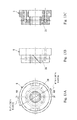
- FIG. 3 illustrates a gear piece (molded article piece).
- FIG. 3A is a plan view of the gear piece
- FIG. 3B is a side view of the gear piece
- FIG. 3C a cross sectional view of a cross section A 1 -A 1 in FIG. 3A of the gear piece.
- FIG. 4 illustrates a first gear piece portion.
- FIG. 4A is a plan view (a cross section A 2 -A 2 in FIG. 3B ) of the first gear piece portion,
- FIG. 4B a side view of the first gear piece portion, and
- FIG. 4C a cross sectional view of a cross section A 4 -A 4 in FIG. 4A .
- FIG. 5 illustrates a second gear piece portion.
- FIG. 5A is a plan view illustrating the second gear piece portion (a cross section A 3 -A 3 in FIG. 3B ),
- FIG. 5B is a side view of the second gear piece portion, and
- FIG. 5C is a cross sectional view of a cross section A 5 -A 5 in FIG. 5A .
- FIG. 6 illustrates a coolant flow path.
- FIG. 6A illustrates the relationship between the gear piece and a movable mold during mold clamping and
- FIG. 6B illustrates the relationship between the gear piece and the movable mold during removal of the molded article after mold opening.
- FIG. 7 illustrates original position restoring means provided in the injection molding die.
- FIG. 7A is a partial plan view of the injection molding die and illustrates the original position restoring means and
- FIG. 7B is a partial side view of the injection molding die and illustrates the original position restoring means.
- FIG. 8A illustrates a first operation state of the original position restoring means
- FIG. 8B illustrates a second operation state of the original position restoring means
- FIG. 8C illustrates a third operation state of the original position restoring means.
- FIG. 9A is a front view of a helical gear
- FIG. 9B illustrates a side view of the helical gear
- FIG. 9C is a cross sectional view of a cross section A 6 -A 6 in FIG. 9A .
- FIG. 10 illustrates modification 1 of the injection molding die according to the embodiment of the invention, more specifically a modification of the coolant flow path.
- FIG. 10A illustrates the relationship between the gear piece and the movable mold during mold clamping and
- FIG. 10B illustrates the relationship between the gear piece and the movable mold during removal of the molded article after mold opening.
- FIG. 11 illustrates modification 1 of the injection molding die according to the embodiment of the invention, more specifically modifications of a piece-side coolant flow path, a movable mold-side supply flow path, and a movable mold-side discharge flow path of the gear piece.
- FIG. 11A is a plan view of the gear piece
- FIG. 11B is a side view of the gear piece
- FIG. 11C is a cross sectional view of a cross section A 7 -A 7 of the gear piece in FIG. 11A .
- FIG. 12 illustrates modification 2 of the injection molding die according to the embodiment of the invention, more specifically a modification of the shape of the cross section of the coolant flow path.
- FIG. 13 illustrates modification 3 of the injection molding die according to the embodiment of the invention, more specifically a part (the relational drawing of the gear piece and the shaft mold) of the injection molding die.
- FIG. 13A is a plan view of the gear piece
- FIG. 13B is a side view of the gear piece
- FIG. 13C is a cross sectional view of a cross section A 8 -A 8 of the gear piece in FIG. 13A .
- FIG. 14 illustrates modification 4 of the injection molding die according to the embodiment of the invention and corresponds to FIG. 6 .
- FIG. 14A illustrates the relationship between the gear piece and the movable mold during mold clamping and
- FIG. 14B illustrates the relationship between the gear piece and the movable mold during removal of the molded article after mold opening.
- FIG. 15 illustrates modification 5 of the injection molding die according to the embodiment of the invention and corresponds to FIG. 6 .
- FIG. 16 illustrates modification 7 of the injection molding die according to the embodiment of the invention, more specifically the injection molding die during mold clamping.
- FIG. 16A is a partial plan view illustrating the movable mold in which the fixed mold is omitted and
- FIG. 16B is a cross sectional view (cross sectional view illustrating a cross section A 9 -A 9 in FIG. 16A ) illustrating the injection molding die.
- FIG. 17 illustrates modification 7 of the injection molding die according to the embodiment of the invention, more specifically the injection molding die during mold opening.
- FIG. 17A is a partial plan view illustrating the movable mold in which the fixed mold is omitted and
- FIG. 17B is a cross sectional view (cross sectional view illustrating a cross section A 10 -A 10 in FIG. 17A ) illustrating the injection molding die.
- FIG. 18 is a cross sectional view illustrating a conventional injection molding die.
- FIGS. 1 and 2 are vertical cross sectional views illustrating an injection molding die 1 according to the embodiment and the injection molding die 1 is used for injection molding of a helical gear 2 (see FIG. 9 ).
- FIG. 1 is a vertical cross sectional view illustrating the injection molding die 1 during mold clamping.
- FIG. 2 is a vertical cross sectional view illustrating the injection molding die 1 during mold opening.
- the injection molding die 1 includes a fixed mold 3 fixed to the main body of the injection molding machine (not illustrated) and a movable mold 4 disposed movably with respect to the fixed mold 3 to enable mold clamping and mold opening.
- the movable mold 4 includes a movable mold main body 5 and a gear piece (molded article piece) 6 housed in the movable mold main body 5 so as to be relatively movable.
- the movable mold main body 5 includes a shaft mold 7 , a first block 8 housing the shaft mold 7 , the second block 10 fixed to the surface (surface facing the fixed mold 3 ) of the first block 8 , and a backup block 11 fixed to the back surface of the first block 8 .
- a gear piece housing recessed portion 12 formed on the outer periphery side of the shaft mold 7 of the movable mold main body 5 a gear piece 6 is housed so as to be relatively movable.
- a shaft hole formation portion 13 at an end of the shaft mold 7 is fitted into a center hole 14 (cavity formation space for forming the cavity 16 ) of the gear piece 6 , so that the cavity 16 is formed by the outer periphery surface of the shaft hole formation portion 13 , the inner surface of the center hole 14 of the gear piece 6 , and a gear piece abutting surface 15 positioned adjacently to the shaft hole formation portion 13 .
- the shaft mold 7 is fitted so that a piece support portion 17 formed adjacently to the shaft hole formation portion 13 is relatively rotatable with respect to a shaft hole 18 of the gear piece 6 .
- the movable mold 4 fits a bearing 21 into an annular bearing reception recessed portion 20 formed in the first block 8 housing the shaft mold 7 and rotatably supports the outer peripheral surface of the gear piece 6 using the bearing 21 .
- the second block 10 is fixed to the surface of the first block 8 close to the fixed mold 3 .
- a gear piece fitting hole 22 is formed so as to be fitted onto the outer peripheral surface of the gear piece 6 with clearance left and an annular bearing reception recessed portion 23 is formed.
- the bearing 21 attached to the movable mold 4 rotatably supports the gear piece 6 .
- the bearing 21 has a side in contact with a side of a flange section 24 of the gear piece 6 and positions the gear piece 6 in the direction along a center axis 25 to prevent the gear piece 6 from being removed from the gear piece housing recessed portion 12 of the movable mold 4 .
- the gear piece 6 is created by integrating the blank of a first gear piece portion 26 with the blank of a second gear piece portion 27 using a metal joint technique (electric pressurizing joint or electric diffusion joint) and then applying various types of removal machining (such as cutting and electric discharging) as appropriate and the gear piece 6 includes a piece-side coolant flow path 28 through which coolant (such as water, ethylene glycol, or oil) flows.
- coolant such as water, ethylene glycol, or oil
- the piece-side coolant flow path 28 includes an annular flow path (cavity cooling flow path) 30 formed along the cavity 16 so as to surround the cavity 16 , a piece-side supply flow path 31 introducing coolant into the annular flow path 30 , and a piece-side discharge flow path 32 introducing the coolant from the annular flow path 30 (see FIG. 6 ).
- the piece-side supply flow path 31 includes the first piece-side supply flow path portion 31 a extending a direction along the center axis 25 of the gear piece 6 , and the second piece-side supply flow path portion 31 b formed on a back surface 33 (surface opposite to the surface facing the fixed mold) of the gear piece 6 .
- the piece-side discharge flow path 32 includes the first piece-side discharge flow path portion 32 a extending in a direction along the center axis 25 of the gear piece 6 and the second piece-side discharge flow path portion 32 b formed on the back surface 33 of the gear piece 6 .
- the second piece-side supply flow path portion 31 b reliably makes connection between the first piece-side supply flow path portion 31 a and a movable mold main body-side supply flow path 34 to enable the coolant to be introduced into the first piece-side supply flow path portion 31 a from the movable mold main body-side supply flow path 34 .
- the second piece-side discharge flow path portion 32 b reliably makes connection between the first piece-side discharge flow path portion 32 a and a movable mold main body-side discharge flow path 35 to enable the coolant to be introduced into the movable mold main body-side discharge flow path 35 from the first piece-side discharge flow path portion 32 a .
- the piece-side supply flow path 31 is connected to the movable mold main body-side supply flow path 34 not only before the gear piece 6 rotates with respect to the movable mold main body 5 , but also after the gear piece 6 rotates by a predetermined angle with respect to the movable mold main body 5 .
- the piece-side discharge flow path 32 is connected to the movable mold main body-side discharge flow path 35 not only before the gear piece 6 rotates with respect to the movable mold main body 5 , but also after the gear piece 6 rotates by a predetermined angle with respect to the movable mold main body 5 .
- Both the second piece-side supply flow path portion 31 b and the second piece-side discharge flow path portion 32 b are circumferential grooves formed across a predetermined angle about the center axis 25 of the gear piece 6 and have semicircular cross sections. That is, the piece-side supply flow path 31 of the gear piece 6 is constantly connected to the movable mold main body-side supply flow path 34 . In addition, the piece-side discharge flow path 32 is constantly connected to the movable mold main body-side discharge flow path 35 . In addition, the movable mold main body-side supply flow path 34 is connected to a coolant supply port 37 of a coolant circulation device 36 and the movable mold main body-side discharge flow path 35 is connected to a coolant discharge port 38 of the coolant circulation device 36 . As described above, the piece-side coolant flow path 28 , the movable mold main body-side supply flow path 34 , and the movable mold main body-side discharge flow path 35 constitute a coolant flow path 40 of the injection molding die 1 .
- the coolant circulation device 36 includes negative pressure generating means (not illustrated), a coolant tank (not illustrated), a heat exchanger (not illustrated), and the like.
- the coolant circulation device 36 circulates the coolant through the coolant flow path 40 of the injection molding die 1 under negative pressure generated by the negative pressure generating means and cools the cooling water heated by the injection molding die 1 so as to repeatedly use the cooling water for cooling the injection molding die 1 .
- the first gear piece portion 26 has a first divided annular flow path 30 a obtained by halving the annular flow path 30 on a joint surface 41 (to which the second gear piece portion 27 jointed).
- the first divided annular flow path 30 a is formed like a ring in the joint surface 41 so as to surround the center hole 14 and has a semicircular cross section.
- the first gear piece portion 26 has the first piece-side supply flow path portion 31 a opened toward the first divided annular flow path 30 a along the center axis 25 and has the first piece-side discharge flow path portion 32 a opened toward the first divided annular flow path 30 a along the center axis 25 in a position deviated from the first piece-side supply flow path portion 31 a by 180 degrees.
- the first piece-side supply flow path portion 31 a and the first piece-side discharge flow path portion 32 a each have one end opened toward the first divided annular flow path 30 a and the other end opened toward the second piece-side supply flow path portion 31 b or the second piece-side discharge flow path portion 32 b formed in the back surface 33 (surface opposite to the joint surface 41 ) of the first gear piece portion 26 .
- the center hole 14 of the first gear piece portion 26 has the length obtained by halving the length in the axial direction of the center hole 14 of the gear piece portion 6 .
- the second gear piece portion 27 has a second divided annular flow path 30 b in a joint surface 42 (surface to which the first gear piece portion 26 is jointed) obtained by halving the annular flow path 30 .
- the second divided annular flow path 30 b is formed like a ring in the joint surface 42 so as to surround the center hole 14 and has a semicircular cross section.
- the joint surface 42 of the second gear piece portion 28 illustrated in FIG. 5 is superimposed on the joint surface 41 of the first gear piece portion 26 illustrated in FIG. 4 and the first gear piece portion 26 is integrated with the second gear piece portion 27 through electric pressurizing joint or electric diffusion joint, the gear piece 6 including the piece-side supply flow path 31 , the annular flow path 30 , and the piece-side discharge flow path 32 is formed.
- FIG. 7 illustrates the structure of original position restoring means 43 returning, to the original position before rotating, the gear piece 6 rotated by a predetermined angle with respect to the movable mold main body 5 .
- the gear piece 6 rotates by a predetermined angle (angle corresponding to the torsion angle of a tooth of the helical gear 2 ) with respect to the movable mold main body 5 (see FIGS. 1, 2, and 6B ).
- the original position restoring means 43 returns the gear piece 6 to the original position before rotating during mold clamping (see FIGS. 1, 2, and 6A ).
- the original position restoring means 43 of the injection molding die 1 includes a cam surface (inclined plane) 45 formed on the gear piece 6 and a cam surface pushing projection 46 placed in the part of the fixed mold 3 facing the gear piece 6 .
- the original position restoring means 43 illustrated in FIG. 7 when the helical gear 2 is pushed out of the cavity 16 by the ejector sleeve 44 and the gear piece 6 rotates by a predetermined angle with respect to the movable mold main body 5 (see FIGS.
- molten synthetic resin material is injected from a plurality of pin gates 47 formed in the fixed mold 3 into the cavity 16 of the movable mold 4 .
- mold opening is performed as illustrated in FIG. 2 and the helical gear 2 in the cavity 16 is pushed out by the ejector sleeve 44 (see FIG. 9 ).
- mold clamping of the injection molding die 1 is performed for the next injection molding (see FIG. 1 ). In this cycle of the injection molding, the coolant constantly flows through the piece-side coolant flow path 28 of the gear piece 6 and the coolant cools the helical gear 2 in the cavity 16 efficiently.
- the injection molding die 1 since the coolant constantly flows through the piece-side supply flow path 31 , the annular flow path 30 , and the piece-side discharge flow path 32 of the gear piece 6 and the heat of the helical gear (molded article) 2 in the cavity 16 is conducted directly to the gear piece 6 by bypassing the air layer and the heat of the gear piece 6 is conducted to the coolant by bypassing the air layer, the helical gear 2 in the cavity 16 is cooled evenly and efficiently.
- the injection molding die 1 according to the embodiment can reduce defective molding caused by the difference in local shrinkage of the helical gear (molded article) 2 .
- the time required for cooling the helical gear 2 in the cavity 16 can be reduced and the cycle time required for injection molding of the helical gear 2 can be reduced as compared with the conventional example.
- the coolant flows through the coolant flow path 40 under negative pressure and the coolant does not leak from the connection portion (relational rotation portion between the gear piece 6 and the movable mold main body 5 ) between the piece-side supply flow path 31 and the movable mold main body-side supply flow path 34 and the connection portion between the piece-side discharge flow path 32 and the movable mold main body-side discharge flow path 35 , a hermetic structure using O-ring or the like does not need in the connection portion between the piece-side supply flow path 31 and the movable mold main body-side supply flow path 34 and the connection portion between the piece-side discharge flow path 32 and the movable mold main body-side discharge flow path 35 and the number of components can be reduced and the mold structure can be simplified as compared with conventional examples.
- the gear precision (tooth error) of the helical gear 2 manufactured by the injection molding die 1 according to the embodiment is JIS level 3, which is higher than the gear precision (JIS level 7) of a helical gear injection-molded using the gear piece 6 not having the coolant flow path 40 .
- the gear piece 6 may be returned to the original position using the elastic force of a spring. That is, the original position restoring means may be a spring.
- the shaft mold 7 , a backup plate 11 , and the like are provided with a temperature adjust fluid path 49 to cool the movable mold 4 and the molded article (for example, the helical gear 2 ) in the cavity 16 using the coolant flowing through the temperature adjust fluid path 49 .
- the injection molding die 1 according to the embodiment can effectively cool a molded article (for example, the helical gear 2 ) in the cavity 16 using the coolant flowing through the piece-side coolant flow path 28 and the coolant flowing through the temperature adjust fluid path 49 , thereby enabling reduction in the cycle time of injection molding.
- the coolant in the temperature adjust fluid path 49 flows under pressure by a pump or the like or under negative pressure generated by the coolant circulation device 36 or the like.
- FIG. 10 illustrates modification 1 of an injection molding die 1 according to the embodiment of the invention, more specifically a modification of the coolant flow path 40 .
- FIG. 10A illustrates the relationship between the gear piece 6 and the movable mold 4 during mold clamping and
- FIG. 10B illustrates the relationship between the gear piece 6 and the movable mold 4 during removal of the molded article after mold opening.
- FIG. 11 illustrates modification 1 of the injection molding die 1 according to the embodiment of the invention, more specifically modifications of the piece-side coolant flow path 28 , the movable mold-side supply flow path 34 , and the movable mold-side discharge flow path 35 .
- FIG. 11A is a plan view of the gear piece 6
- FIG. 11B is a side view of the gear piece 6
- FIG. 11C is a cross sectional view of a cross section A 7 -A 7 of the gear piece 6 in FIG. 11A .
- the coolant flow path 40 of the injection molding die 1 according to modification 1 is the same as the coolant flow path 40 of the injection molding die 1 according to the first embodiment in that the coolant flow path 40 includes the movable mold main body-side supply flow path 34 , the piece-side supply flow path 31 , the annular flow path 30 , the piece-side discharge flow path 32 , and the movable mold main body-side discharge flow path 35 .
- the first movable mold main body-side supply flow path portion 34 a and the second movable mold main body-side supply flow path portion 34 b constitute the movable mold main body-side supply flow path 34 and the first movable mold main body-side discharge flow path portion 35 a and a second movable mold main body-side discharge flow path portion 35 b constitute the movable mold main body-side discharge flow path 35 .
- the coolant flow path 40 of the injection molding die 1 according to modification 1 has the second movable mold main body-side supply flow path portion 34 b and the second movable mold main body-side discharge flow path portion 35 b as circumferential grooves in place of the second piece-side supply flow path portion 31 b and the second piece-side discharge flow path portion 32 b in the coolant flow path 40 of the injection molding die 1 according to the embodiment.
- the second movable mold main body-side supply flow path 34 b and the second movable mold main body-side discharge flow path 35 b are circumferential grooves formed in the surface (surface on which the gear piece 6 slides) of the movable mold main body 5 facing the gear piece 6 so as to constantly connect the first movable mold main body-side supply flow path portion 34 a to constantly connect the piece-side supply flow path 31 and constantly connect the piece-side discharge flow path 32 to the first movable mold main body-side discharge flow path portion 35 a even when the gear piece 6 rotates by predetermined angle with respect to the movable mold main body 5 .
- the injection molding die 1 having the coolant flow path 40 according to modification 1 can obtain effects similar to those of the above embodiment.
- FIG. 12 illustrates the shape of the cross section of the coolant flow path 40 according to modification 2 of the embodiment.
- the shape of the cross section of the coolant flow path 40 is not limited to a circle or semicircle illustrated in the above embodiment and modification 1 and may be, for example, a rectangle (see FIG. 12A ) or trapezoid (see FIG. 12B ).
- FIG. 13 illustrates modification 3 of the injection molding die 1 according to the above embodiment, more specifically a part (the relationship between the gear piece 6 and the movable mold main body 5 ) of the injection molding die 1 .
- FIG. 13A is a plan view of the gear piece 6
- FIG. 13B is a side view of the gear piece 6
- FIG. 13C is a cross sectional view of a cross section A 8 -A 8 of the gear piece 6 in FIG. 13A .
- the gear piece 6 according to the modification is integrally formed using a metal lamination modeling technique (such as metal powder laser lamination or molten metal lamination) and the piece-side coolant flow path 28 is formed internally.
- a metal lamination modeling technique such as metal powder laser lamination or molten metal lamination
- the other of the structure is the same as in the gear piece 6 according to the above embodiment. Accordingly, the injection molding die 1 including the gear piece 6 according to the modification can obtain effects similar to those of the injection molding die 1 according to the above embodiment.
- a desired dimensional accuracy is achieved by creating a gear piece blank using a metal lamination modeling technique and then applying various types of removal machining (such as cutting and electric discharging) to the gear piece blank.
- FIG. 14 illustrates modification 4 of the injection molding die 1 according to the embodiment and corresponds to FIG. 6 .
- FIG. 14A illustrates the relationship between the gear piece 6 and the movable mold 5 during mold clamping and
- FIG. 14B illustrates the relationship between the gear piece 6 and the movable mold 5 during removal of the molded article after mold opening.
- the injection molding die 1 according to the modification does not have the second piece-side supply flow path portion 31 b and the second piece-side discharge flow path portion 32 b of the injection molding die 1 according to the above embodiment and does not have the second movable mold main body-side supply flow path portion 34 b and the second movable mold main body-side discharge flow path portion 35 b of the injection molding die 1 according to modification 1.
- the movable mold main body-side supply flow path 34 is connected to the piece-side supply flow path 31 and the piece-side discharge flow path 32 is connected to the movable mold main body-side discharge flow path 35 , so that the coolant reliably flows through the piece-side coolant flow path 28 (see FIG. 14A ).
- the original position restoring means 43 returns the gear piece 6 to the original position before rotating
- the movable mold main body-side supply flow path 34 is connected to the piece-side supply flow path 31
- the piece-side discharge flow path 32 is connected to the movable mold main body-side discharge flow path 35
- the coolant is newly supplied to the piece-side coolant flow path 28 in the gear piece 6 (see FIGS. 7, 8, and 14A ).
- FIG. 15 illustrates modification 5 of the injection molding die 1 according to the embodiment and corresponds to FIG. 6 .
- the original position restoring means 43 in the above embodiment is omitted and the gear piece 6 rotates by a predetermined angle with respect to the movable mold main body 5 in the same direction each time the helical gear (molded article) 2 is removed from the cavity 16 .
- a plurality of flow paths 48 are formed to make connection between the annular flow path 30 and the movable mold main body-side supply flow path 34 and connection between the annular flow path 30 and the movable mold main body-side discharge flow path 35 so that the piece-side supply flow path 28 in the gear piece 6 communicates with the movable mold main body-side supply flow path 34 and the piece-side supply flow path 28 in the gear piece 6 communicates with the movable mold main body-side discharge flow path 35 even when the gear piece 6 rotates in steps of the predetermined angle.
- One of the plurality of flow paths 48 becomes a piece-side supply flow path connecting the annular flow path 30 to the movable mold main body-side supply flow path 34 and another of the plurality of flow paths 48 becomes a piece-side discharge flow path connecting the annular flow path 30 to the movable mold main body-side discharge flow path 35 .
- the helical gear 2 is illustrated as the molded article piece in the injection molding dies 1 according to the above embodiment and modifications 1 to 3, the invention is not limited to the examples and applicable to the injection molding of a screw gear, a helical gear, a warm wheel, a double herringbone gear (gear configured by continuously integrating a small-diameter helical gear with a large-diameter helical gear in the axial direction), a pump bladed wheel, and the like in which the molded article piece (for example, a gear piece) rotates with respect to the movable mold main body 5 .
- injection molding dies 1 according to the above embodiment and modifications 1 to 3 are applicable to the injection molding of an object in which the molded article piece ( 6 ) does not need to rotate with respect to the movable mold main body 5 and effects similar to those of the above embodiment can be obtained.
- the molded article piece (for example, the gear piece 6 ) rotates with respect to the movable mold main body 5 in the above embodiment and modifications 1 to 3, the invention is applicable to the case in which the molded article piece slides with respect to the movable mold main body 5 .
- FIGS. 16 and 17 illustrate an injection molding die 51 according to the modification.
- FIG. 16 illustrates the injection molding die 51 during mold clamping
- FIG. 16A is a partial plan view of a movable mold 53 in which a fixed mold 52 is not illustrated
- FIG. 16B is a cross sectional view of the injection molding die 51 (cross sectional view of a cross section A 9 -A 9 in FIG. 16A ).
- FIG. 17 illustrates the injection molding die 51 during mold opening
- FIG. 17A is a partial plan view of the movable mold 53 in which the fixed mold 52 is not illustrated
- FIG. 17B is a cross sectional view of the injection molding die 51 (cross sectional view of a cross section A 10 -A 10 in FIG. 17A ).
- the injection molding die 51 includes the fixed mold 52 and the movable mold 53 performing mold clamping and mold opening with respect to the fixed mold 52 (see FIG. 17 ).
- the movable mold 53 includes a movable mold main body 54 and a molded article piece 55 attached to the movable mold main body 54 so as to be relatively movable (slidable) with respect to the movable mold main body 54 .
- the movable mold main body 54 includes a shaft mold 56 and a base block 57 to which the shaft mold 56 is assembled.
- the molded article piece 55 is divided into a first molded article piece 55 A and a second molded article piece 55 B and the first molded article piece 55 A and the second molded article piece 55 B form a cavity 58 between the shaft mold 56 and the fixed mold 52 during mold clamping. Molten resin is injected to the cavity 58 from a pin point gate 60 installed in the fixed mold 52 .
- pins 61 pins 61 for making holes in the side of a molded article 62 ) attached to the first molded article piece 55 A and the second molded article piece 55 B project in the cavity 58 (see FIG. 17 ).
- the first molded article piece 55 A and the second molded article piece 55 B slides along the surface 57 a of the base block 57 until the first molded article piece 55 A and the second molded article piece 55 B abut against a stopper 63 placed in the base block 57 .
- the molded article 62 is a bottomed cylinder having a plurality of holes on the side thereof.
- the molded article 62 is illustrated as a bottomed cylinder in FIGS. 16 and 17 according to the modification, the molded article 62 is not limited to this example and the invention may be applied to the formation of a bottomed hollow body having a triangle cross section, a bottomed hollow body having a rectangular cross section, or a bottomed hollow body having a polygonal cross section.
- a rod-like cavity formation space 64 is formed internally in the state in which the first molded article piece 55 A and the second molded article piece 55 B abut against each other as illustrated in FIG. 16 .
- the first molded article piece 55 A and the second molded article piece 55 B include semi-cylindrical flow paths (cavity cooling flow paths) 65 formed along cavity formation space 64 , the piece-side supply flow paths 66 introducing the coolant into the semi-cylindrical flow paths 65 , and the piece-side discharge flow paths 67 introducing the coolant from the semi-cylindrical flow paths 65 .
- the piece-side supply flow paths 66 of the first molded article piece 55 A and the second molded article piece 55 B are connected to movable mold main body-side supply flow paths 68 formed in the movable mold main body 54 .
- the piece-side discharge flow paths 67 of the first molded article piece 55 A and the second molded article piece 55 B are connected to movable mold main body-side discharge flow paths 70 formed in the movable mold main body 54 .
- the movable mold main body-side supply flow path 68 is connected to the coolant supply port 37 of the coolant circulation device 36 .
- the movable mold main body-side discharge flow path 70 is connected to the coolant discharge port 38 of the coolant circulation device 36 .
- the piece-side supply flow paths 66 of the first molded article piece 55 A and the second molded article piece 55 B include the first piece-side supply flow path portions 66 a connected to the semi-cylindrical flow paths 65 and the second piece-side supply flow path portions 66 b connected to the movable mold main body-side supply flow paths 68 .
- the second piece-side supply flow path portions 66 b are long grooves formed along the sliding direction of the first molded article piece 55 A or the second molded article piece 55 B so as to constantly connect the first piece-side supply flow paths 66 a and the movable mold main body-side supply flow paths 68 .
- “constantly” means one cycle from the state (mold clamping state) in which the first molded article piece 55 A abuts against the second molded article piece 55 B to the state in which the first molded article piece 55 A abuts against the second molded article piece 55 B again through the state in which the first molded article piece 55 A and the second molded article piece 55 B slide until they abut against the stopper 63 .
- the piece-side discharge flow paths 67 of the first molded article piece 55 A and the second molded article piece 55 B include the first piece-side discharge flow path portions 67 a connected to a semi-cylindrical flow paths 65 and second piece-side discharge flow path portions 67 b connected to the movable mold main body-side discharge flow paths 70 .
- the second piece-side discharge flow path portions 67 b are long grooves formed along the sliding direction of the first molded article piece 55 A or the second molded article piece 55 B so as to constantly connect the first piece-side discharge flow paths 67 a and the movable mold main body-side discharge flow paths 70 .
- the second piece-side supply flow path portion 66 b and the second piece-side discharge flow path portion 67 b are formed in the parts of the first molded article piece 55 A and the second molded article piece 55 B close to a slide surface 71 (surface in slidable contact with the movable mold main body) in the modification
- the invention is not limited to this example and long grooves functioning as the second piece-side supply flow path portion 66 b and the second piece-side discharge flow path portion 67 b may be formed at the end portion of the movable mold main body-side supply flow path 68 and the end portion of the movable mold main body-side discharge flow path 70 .
- the first molded article piece 55 A and the second molded article piece 55 B are formed, as in the gear piece 6 according to the above embodiment, by creating a molded article piece blank using a metal joint technique (electric pressurizing joint or electric diffusion joint) or a metal lamination modeling technique (such as metal powder laser lamination or molten metal lamination) and then performing cutting or the like as appropriate.
- a metal joint technique electric pressurizing joint or electric diffusion joint
- a metal lamination modeling technique such as metal powder laser lamination or molten metal lamination
- the semi-cylindrical flow path 65 of the first molded article piece 55 A and the semi-cylindrical flow path 65 of the second molded article piece 55 B each have a shape obtained by halving a cylindrical flow path (virtual flow path surrounding the cavity 58 ), in the state in which the first molded article piece 55 A abuts against the second molded article piece 55 B during mold clamping, a combination of the semi-cylindrical flow path 65 of the first molded article piece 55 A and the semi-cylindrical flow path 65 of the second molded article piece 55 B functions as a cylindrical flow path.
- the cavity 58 inside the first molded article piece 55 A and the second molded article piece 55 B is cooled by the coolant flowing through the piece-side supply flow path 66 , the semi-cylindrical flow path 65 , and the piece-side discharge flow path 67 under negative pressure and effects similar to those of the injection molding die 1 according to the above embodiment can be obtained.
- the shaft mold 56 and the like are provided with a temperature adjust fluid path 72 and the coolant flowing through the temperature adjust fluid path 72 cools the movable mold 53 and the molded article 62 in the cavity 58 .
- the injection molding die 51 according to the modification can effectively cool the molded article 62 in the cavity 58 using the coolant flowing through the semi-cylindrical flow path (cavity cooling flow path) 65 and the coolant flowing through the temperature adjust fluid path 72 , thereby enabling reduction in the cycle time of injection molding.
- the coolant in the temperature adjust fluid path 72 flows under pressure by a pump or the like or under negative pressure generated by the coolant circulation device 36 or the like.
- the pins 61 attached to the first molded article piece 55 A and the second molded article piece 55 B penetrate through the semi-cylindrical flow path 65 and project into the cavity 58 .
- the coolant in the semi-cylindrical flow path 65 flows under negative pressure, the coolant in the semi-cylindrical flow path 65 does no leak from the gap between the pins 61 and the first molded article piece 55 A and the gap between the pins 61 and the second molded article piece 55 B into the cavity 58 .
Landscapes
- Engineering & Computer Science (AREA)
- Mechanical Engineering (AREA)
- Manufacturing & Machinery (AREA)
- Physics & Mathematics (AREA)
- Fluid Mechanics (AREA)
- Moulds For Moulding Plastics Or The Like (AREA)
Applications Claiming Priority (3)
| Application Number | Priority Date | Filing Date | Title |
|---|---|---|---|
| JP2013-196639 | 2013-09-24 | ||
| JP2013196639A JP6231836B2 (ja) | 2013-09-24 | 2013-09-24 | 射出成形金型 |
| PCT/JP2014/071536 WO2015045671A1 (ja) | 2013-09-24 | 2014-08-18 | 射出成形金型 |
Publications (2)
| Publication Number | Publication Date |
|---|---|
| US20160207232A1 US20160207232A1 (en) | 2016-07-21 |
| US10011059B2 true US10011059B2 (en) | 2018-07-03 |
Family
ID=52742825
Family Applications (1)
| Application Number | Title | Priority Date | Filing Date |
|---|---|---|---|
| US15/023,467 Expired - Fee Related US10011059B2 (en) | 2013-09-24 | 2014-08-18 | Injection molding die |
Country Status (3)
| Country | Link |
|---|---|
| US (1) | US10011059B2 (ja) |
| JP (1) | JP6231836B2 (ja) |
| WO (1) | WO2015045671A1 (ja) |
Families Citing this family (7)
| Publication number | Priority date | Publication date | Assignee | Title |
|---|---|---|---|---|
| CN106079328B (zh) * | 2016-08-04 | 2018-07-27 | 江苏文光模具技术有限公司 | 一种注塑模具的水路转接结构 |
| CN106825417A (zh) * | 2017-04-02 | 2017-06-13 | 盐城市德邦机械制造有限公司 | 一种铸造模具的定点冷却排气结构 |
| CN109128084B (zh) * | 2018-09-19 | 2021-05-11 | 宁波环亚机械制造有限公司 | 压铸模冷却装置及冷却方法 |
| IT201900004251A1 (it) | 2019-03-25 | 2020-09-25 | Skf Ab | Modulo integrato elemento di cuscinetto - montante di sospensione e suo metodo di produzione |
| CN111186088B (zh) * | 2020-01-14 | 2021-09-07 | 广东伟力环保实业有限公司 | 一种旋转脱模式注塑模具 |
| CN112427606A (zh) * | 2020-10-21 | 2021-03-02 | 德盛镁汽车部件(芜湖)有限公司 | 一种布置在发动机缸盖生产线上的铸造模具 |
| CN116061395A (zh) * | 2023-02-11 | 2023-05-05 | 广东景荣科技控股有限公司 | 一种注塑模具 |
Citations (8)
| Publication number | Priority date | Publication date | Assignee | Title |
|---|---|---|---|---|
| JPH07195443A (ja) | 1993-12-28 | 1995-08-01 | Mitsubishi Materials Corp | 射出成形金型 |
| JPH08216161A (ja) | 1995-02-09 | 1996-08-27 | Fuji Seiki Kk | 樹脂成形用金型装置 |
| JPH1158465A (ja) | 1997-08-15 | 1999-03-02 | Ricoh Co Ltd | 射出成形品の製造用金型 |
| DE10022289A1 (de) * | 2000-05-09 | 2001-11-29 | Innova Engineering Gmbh | Vorrichtung zum Herstellen eines zu temperierenden Werkstücks und Verfahren zum Herstellen eines hülsenförmigen Elements |
| JP2003039437A (ja) | 2001-07-31 | 2003-02-13 | Suwa Netsukogyo Kk | 温度調節用流体通路付き成形型及びその製造方法 |
| US20060249862A1 (en) * | 2005-05-09 | 2006-11-09 | Vince Ciccone | Grooved-surface air conduit for injection molds |
| JP2007130902A (ja) | 2005-11-10 | 2007-05-31 | Ricoh Co Ltd | 射出成形用金型 |
| US20130009345A1 (en) | 2011-07-04 | 2013-01-10 | Canon Kabushiki Kaisha | Method of manufacturing a resin molded gear by injection molding |
-
2013
- 2013-09-24 JP JP2013196639A patent/JP6231836B2/ja not_active Expired - Fee Related
-
2014
- 2014-08-18 US US15/023,467 patent/US10011059B2/en not_active Expired - Fee Related
- 2014-08-18 WO PCT/JP2014/071536 patent/WO2015045671A1/ja not_active Ceased
Patent Citations (9)
| Publication number | Priority date | Publication date | Assignee | Title |
|---|---|---|---|---|
| JPH07195443A (ja) | 1993-12-28 | 1995-08-01 | Mitsubishi Materials Corp | 射出成形金型 |
| JPH08216161A (ja) | 1995-02-09 | 1996-08-27 | Fuji Seiki Kk | 樹脂成形用金型装置 |
| JPH1158465A (ja) | 1997-08-15 | 1999-03-02 | Ricoh Co Ltd | 射出成形品の製造用金型 |
| DE10022289A1 (de) * | 2000-05-09 | 2001-11-29 | Innova Engineering Gmbh | Vorrichtung zum Herstellen eines zu temperierenden Werkstücks und Verfahren zum Herstellen eines hülsenförmigen Elements |
| JP2003039437A (ja) | 2001-07-31 | 2003-02-13 | Suwa Netsukogyo Kk | 温度調節用流体通路付き成形型及びその製造方法 |
| US20060249862A1 (en) * | 2005-05-09 | 2006-11-09 | Vince Ciccone | Grooved-surface air conduit for injection molds |
| JP2007130902A (ja) | 2005-11-10 | 2007-05-31 | Ricoh Co Ltd | 射出成形用金型 |
| US20130009345A1 (en) | 2011-07-04 | 2013-01-10 | Canon Kabushiki Kaisha | Method of manufacturing a resin molded gear by injection molding |
| JP2013014075A (ja) | 2011-07-04 | 2013-01-24 | Canon Inc | 射出成形による樹脂成形歯車の製造方法 |
Non-Patent Citations (1)
| Title |
|---|
| International Search Report dated Nov. 4, 2014 in corresponding International Application No. PCT/JP/2014/071536 (with English translation). |
Also Published As
| Publication number | Publication date |
|---|---|
| WO2015045671A1 (ja) | 2015-04-02 |
| JP6231836B2 (ja) | 2017-11-15 |
| JP2015063013A (ja) | 2015-04-09 |
| US20160207232A1 (en) | 2016-07-21 |
Similar Documents
| Publication | Publication Date | Title |
|---|---|---|
| US10011059B2 (en) | Injection molding die | |
| KR101821859B1 (ko) | 광학 소자의 제조를 위한 성형 공구 및 방법 | |
| TWI750270B (zh) | 冷卻液聯結裝置 | |
| JP2016097645A (ja) | ローラ部材の製造方法、ローラ部材金型、ローラ軸、およびローラ部材 | |
| CA2399758A1 (en) | Method and apparatus for eliminating a parting line witness mark from a molded part | |
| CN100469553C (zh) | 金属模装置、模制品、其成形方法、成形机和衬套 | |
| JP2005296972A (ja) | 金型冷却構造 | |
| JP6787727B2 (ja) | 中空成形品の製造方法 | |
| CN107708959B (zh) | 用于注塑机的模具堆叠 | |
| KR101554491B1 (ko) | 라디에이터 그릴 성형용 사출 성형 금형 및 그 제조 방법 | |
| JP4486145B2 (ja) | 熱硬化性樹脂用の射出成形装置 | |
| JP6998187B2 (ja) | 中空円盤状スラストワッシャの製造方法 | |
| FR3041894A1 (fr) | Moule d’injection a chargeur de transfert et procede d’injection associe | |
| JP2010221550A (ja) | 偏心体の製造方法、偏心体 | |
| JP3843773B2 (ja) | 型内被覆成形用金型および型内被覆成形方法 | |
| JP2013212593A (ja) | 成形品の製造方法及び製造装置 | |
| KR101969541B1 (ko) | 핫 런너 매니폴드 시스템 및 그 제조방법 | |
| JP2002283410A (ja) | バルブゲート式金型装置およびこれを用いた成形方法 | |
| JP4235053B2 (ja) | 鋳造型の密閉式離型剤塗布システム | |
| KR20170050567A (ko) | 볼밸브용 볼의 수지 라이닝 장치 및 방법 | |
| JP7255233B2 (ja) | 成形型 | |
| CN101175623A (zh) | 盘成形用金属模、其制造方法及金属模部件 | |
| US20230182348A1 (en) | Tool assembly for manufacturing parts and a method of producing a tool assembly | |
| JP2005280266A (ja) | 成形型及びその製造方法 | |
| JP2025007257A (ja) | 金型装置 |
Legal Events
| Date | Code | Title | Description |
|---|---|---|---|
| AS | Assignment |
Owner name: ENPLAS CORPORATION, JAPAN Free format text: ASSIGNMENT OF ASSIGNORS INTEREST;ASSIGNOR:HASHIMOTO, MASAOMI;REEL/FRAME:038048/0287 Effective date: 20160314 |
|
| STCF | Information on status: patent grant |
Free format text: PATENTED CASE |
|
| FEPP | Fee payment procedure |
Free format text: MAINTENANCE FEE REMINDER MAILED (ORIGINAL EVENT CODE: REM.); ENTITY STATUS OF PATENT OWNER: LARGE ENTITY |
|
| LAPS | Lapse for failure to pay maintenance fees |
Free format text: PATENT EXPIRED FOR FAILURE TO PAY MAINTENANCE FEES (ORIGINAL EVENT CODE: EXP.); ENTITY STATUS OF PATENT OWNER: LARGE ENTITY |
|
| STCH | Information on status: patent discontinuation |
Free format text: PATENT EXPIRED DUE TO NONPAYMENT OF MAINTENANCE FEES UNDER 37 CFR 1.362 |
|
| FP | Lapsed due to failure to pay maintenance fee |
Effective date: 20220703 |