RU2406591C2 - Jointing diverse materials - Google Patents
Jointing diverse materials Download PDFInfo
- Publication number
- RU2406591C2 RU2406591C2 RU2007124484A RU2007124484A RU2406591C2 RU 2406591 C2 RU2406591 C2 RU 2406591C2 RU 2007124484 A RU2007124484 A RU 2007124484A RU 2007124484 A RU2007124484 A RU 2007124484A RU 2406591 C2 RU2406591 C2 RU 2406591C2
- Authority
- RU
- Russia
- Prior art keywords
- ductile material
- less
- decorated
- ceramic
- joined
- Prior art date
Links
Images


Classifications
-
- H—ELECTRICITY
- H01—ELECTRIC ELEMENTS
- H01M—PROCESSES OR MEANS, e.g. BATTERIES, FOR THE DIRECT CONVERSION OF CHEMICAL ENERGY INTO ELECTRICAL ENERGY
- H01M4/00—Electrodes
- H01M4/86—Inert electrodes with catalytic activity, e.g. for fuel cells
- H01M4/8647—Inert electrodes with catalytic activity, e.g. for fuel cells consisting of more than one material, e.g. consisting of composites
- H01M4/8657—Inert electrodes with catalytic activity, e.g. for fuel cells consisting of more than one material, e.g. consisting of composites layered
-
- B—PERFORMING OPERATIONS; TRANSPORTING
- B23—MACHINE TOOLS; METAL-WORKING NOT OTHERWISE PROVIDED FOR
- B23K—SOLDERING OR UNSOLDERING; WELDING; CLADDING OR PLATING BY SOLDERING OR WELDING; CUTTING BY APPLYING HEAT LOCALLY, e.g. FLAME CUTTING; WORKING BY LASER BEAM
- B23K35/00—Rods, electrodes, materials, or media, for use in soldering, welding, or cutting
- B23K35/22—Rods, electrodes, materials, or media, for use in soldering, welding, or cutting characterised by the composition or nature of the material
- B23K35/24—Selection of soldering or welding materials proper
- B23K35/28—Selection of soldering or welding materials proper with the principal constituent melting at less than 950 degrees C
-
- B—PERFORMING OPERATIONS; TRANSPORTING
- B23—MACHINE TOOLS; METAL-WORKING NOT OTHERWISE PROVIDED FOR
- B23K—SOLDERING OR UNSOLDERING; WELDING; CLADDING OR PLATING BY SOLDERING OR WELDING; CUTTING BY APPLYING HEAT LOCALLY, e.g. FLAME CUTTING; WORKING BY LASER BEAM
- B23K35/00—Rods, electrodes, materials, or media, for use in soldering, welding, or cutting
- B23K35/22—Rods, electrodes, materials, or media, for use in soldering, welding, or cutting characterised by the composition or nature of the material
- B23K35/24—Selection of soldering or welding materials proper
- B23K35/30—Selection of soldering or welding materials proper with the principal constituent melting at less than 1550 degrees C
-
- B—PERFORMING OPERATIONS; TRANSPORTING
- B23—MACHINE TOOLS; METAL-WORKING NOT OTHERWISE PROVIDED FOR
- B23K—SOLDERING OR UNSOLDERING; WELDING; CLADDING OR PLATING BY SOLDERING OR WELDING; CUTTING BY APPLYING HEAT LOCALLY, e.g. FLAME CUTTING; WORKING BY LASER BEAM
- B23K35/00—Rods, electrodes, materials, or media, for use in soldering, welding, or cutting
- B23K35/22—Rods, electrodes, materials, or media, for use in soldering, welding, or cutting characterised by the composition or nature of the material
- B23K35/24—Selection of soldering or welding materials proper
- B23K35/32—Selection of soldering or welding materials proper with the principal constituent melting at more than 1550 degrees C
-
- C—CHEMISTRY; METALLURGY
- C04—CEMENTS; CONCRETE; ARTIFICIAL STONE; CERAMICS; REFRACTORIES
- C04B—LIME, MAGNESIA; SLAG; CEMENTS; COMPOSITIONS THEREOF, e.g. MORTARS, CONCRETE OR LIKE BUILDING MATERIALS; ARTIFICIAL STONE; CERAMICS; REFRACTORIES; TREATMENT OF NATURAL STONE
- C04B37/00—Joining burned ceramic articles with other burned ceramic articles or other articles by heating
- C04B37/02—Joining burned ceramic articles with other burned ceramic articles or other articles by heating with metallic articles
- C04B37/023—Joining burned ceramic articles with other burned ceramic articles or other articles by heating with metallic articles characterised by the interlayer used
- C04B37/025—Joining burned ceramic articles with other burned ceramic articles or other articles by heating with metallic articles characterised by the interlayer used consisting of glass or ceramic material
-
- H—ELECTRICITY
- H01—ELECTRIC ELEMENTS
- H01M—PROCESSES OR MEANS, e.g. BATTERIES, FOR THE DIRECT CONVERSION OF CHEMICAL ENERGY INTO ELECTRICAL ENERGY
- H01M4/00—Electrodes
- H01M4/86—Inert electrodes with catalytic activity, e.g. for fuel cells
- H01M4/8605—Porous electrodes
-
- H—ELECTRICITY
- H01—ELECTRIC ELEMENTS
- H01M—PROCESSES OR MEANS, e.g. BATTERIES, FOR THE DIRECT CONVERSION OF CHEMICAL ENERGY INTO ELECTRICAL ENERGY
- H01M4/00—Electrodes
- H01M4/86—Inert electrodes with catalytic activity, e.g. for fuel cells
- H01M4/88—Processes of manufacture
- H01M4/8878—Treatment steps after deposition of the catalytic active composition or after shaping of the electrode being free-standing body
- H01M4/8882—Heat treatment, e.g. drying, baking
- H01M4/8885—Sintering or firing
-
- H—ELECTRICITY
- H01—ELECTRIC ELEMENTS
- H01M—PROCESSES OR MEANS, e.g. BATTERIES, FOR THE DIRECT CONVERSION OF CHEMICAL ENERGY INTO ELECTRICAL ENERGY
- H01M4/00—Electrodes
- H01M4/86—Inert electrodes with catalytic activity, e.g. for fuel cells
- H01M4/90—Selection of catalytic material
- H01M4/9041—Metals or alloys
- H01M4/905—Metals or alloys specially used in fuel cell operating at high temperature, e.g. SOFC
- H01M4/9066—Metals or alloys specially used in fuel cell operating at high temperature, e.g. SOFC of metal-ceramic composites or mixtures, e.g. cermets
-
- H—ELECTRICITY
- H01—ELECTRIC ELEMENTS
- H01M—PROCESSES OR MEANS, e.g. BATTERIES, FOR THE DIRECT CONVERSION OF CHEMICAL ENERGY INTO ELECTRICAL ENERGY
- H01M8/00—Fuel cells; Manufacture thereof
- H01M8/02—Details
- H01M8/0297—Arrangements for joining electrodes, reservoir layers, heat exchange units or bipolar separators to each other
-
- H—ELECTRICITY
- H01—ELECTRIC ELEMENTS
- H01M—PROCESSES OR MEANS, e.g. BATTERIES, FOR THE DIRECT CONVERSION OF CHEMICAL ENERGY INTO ELECTRICAL ENERGY
- H01M8/00—Fuel cells; Manufacture thereof
- H01M8/10—Fuel cells with solid electrolytes
- H01M8/12—Fuel cells with solid electrolytes operating at high temperature, e.g. with stabilised ZrO2 electrolyte
- H01M8/124—Fuel cells with solid electrolytes operating at high temperature, e.g. with stabilised ZrO2 electrolyte characterised by the process of manufacturing or by the material of the electrolyte
- H01M8/1246—Fuel cells with solid electrolytes operating at high temperature, e.g. with stabilised ZrO2 electrolyte characterised by the process of manufacturing or by the material of the electrolyte the electrolyte consisting of oxides
- H01M8/1253—Fuel cells with solid electrolytes operating at high temperature, e.g. with stabilised ZrO2 electrolyte characterised by the process of manufacturing or by the material of the electrolyte the electrolyte consisting of oxides the electrolyte containing zirconium oxide
-
- C—CHEMISTRY; METALLURGY
- C04—CEMENTS; CONCRETE; ARTIFICIAL STONE; CERAMICS; REFRACTORIES
- C04B—LIME, MAGNESIA; SLAG; CEMENTS; COMPOSITIONS THEREOF, e.g. MORTARS, CONCRETE OR LIKE BUILDING MATERIALS; ARTIFICIAL STONE; CERAMICS; REFRACTORIES; TREATMENT OF NATURAL STONE
- C04B2237/00—Aspects relating to ceramic laminates or to joining of ceramic articles with other articles by heating
- C04B2237/02—Aspects relating to interlayers, e.g. used to join ceramic articles with other articles by heating
- C04B2237/04—Ceramic interlayers
- C04B2237/06—Oxidic interlayers
- C04B2237/068—Oxidic interlayers based on refractory oxides, e.g. zirconia
-
- C—CHEMISTRY; METALLURGY
- C04—CEMENTS; CONCRETE; ARTIFICIAL STONE; CERAMICS; REFRACTORIES
- C04B—LIME, MAGNESIA; SLAG; CEMENTS; COMPOSITIONS THEREOF, e.g. MORTARS, CONCRETE OR LIKE BUILDING MATERIALS; ARTIFICIAL STONE; CERAMICS; REFRACTORIES; TREATMENT OF NATURAL STONE
- C04B2237/00—Aspects relating to ceramic laminates or to joining of ceramic articles with other articles by heating
- C04B2237/30—Composition of layers of ceramic laminates or of ceramic or metallic articles to be joined by heating, e.g. Si substrates
- C04B2237/32—Ceramic
- C04B2237/34—Oxidic
- C04B2237/343—Alumina or aluminates
-
- C—CHEMISTRY; METALLURGY
- C04—CEMENTS; CONCRETE; ARTIFICIAL STONE; CERAMICS; REFRACTORIES
- C04B—LIME, MAGNESIA; SLAG; CEMENTS; COMPOSITIONS THEREOF, e.g. MORTARS, CONCRETE OR LIKE BUILDING MATERIALS; ARTIFICIAL STONE; CERAMICS; REFRACTORIES; TREATMENT OF NATURAL STONE
- C04B2237/00—Aspects relating to ceramic laminates or to joining of ceramic articles with other articles by heating
- C04B2237/30—Composition of layers of ceramic laminates or of ceramic or metallic articles to be joined by heating, e.g. Si substrates
- C04B2237/32—Ceramic
- C04B2237/34—Oxidic
- C04B2237/345—Refractory metal oxides
- C04B2237/348—Zirconia, hafnia, zirconates or hafnates
-
- C—CHEMISTRY; METALLURGY
- C04—CEMENTS; CONCRETE; ARTIFICIAL STONE; CERAMICS; REFRACTORIES
- C04B—LIME, MAGNESIA; SLAG; CEMENTS; COMPOSITIONS THEREOF, e.g. MORTARS, CONCRETE OR LIKE BUILDING MATERIALS; ARTIFICIAL STONE; CERAMICS; REFRACTORIES; TREATMENT OF NATURAL STONE
- C04B2237/00—Aspects relating to ceramic laminates or to joining of ceramic articles with other articles by heating
- C04B2237/30—Composition of layers of ceramic laminates or of ceramic or metallic articles to be joined by heating, e.g. Si substrates
- C04B2237/40—Metallic
- C04B2237/401—Cermets
-
- C—CHEMISTRY; METALLURGY
- C04—CEMENTS; CONCRETE; ARTIFICIAL STONE; CERAMICS; REFRACTORIES
- C04B—LIME, MAGNESIA; SLAG; CEMENTS; COMPOSITIONS THEREOF, e.g. MORTARS, CONCRETE OR LIKE BUILDING MATERIALS; ARTIFICIAL STONE; CERAMICS; REFRACTORIES; TREATMENT OF NATURAL STONE
- C04B2237/00—Aspects relating to ceramic laminates or to joining of ceramic articles with other articles by heating
- C04B2237/30—Composition of layers of ceramic laminates or of ceramic or metallic articles to be joined by heating, e.g. Si substrates
- C04B2237/40—Metallic
- C04B2237/405—Iron metal group, e.g. Co or Ni
- C04B2237/406—Iron, e.g. steel
-
- C—CHEMISTRY; METALLURGY
- C04—CEMENTS; CONCRETE; ARTIFICIAL STONE; CERAMICS; REFRACTORIES
- C04B—LIME, MAGNESIA; SLAG; CEMENTS; COMPOSITIONS THEREOF, e.g. MORTARS, CONCRETE OR LIKE BUILDING MATERIALS; ARTIFICIAL STONE; CERAMICS; REFRACTORIES; TREATMENT OF NATURAL STONE
- C04B2237/00—Aspects relating to ceramic laminates or to joining of ceramic articles with other articles by heating
- C04B2237/30—Composition of layers of ceramic laminates or of ceramic or metallic articles to be joined by heating, e.g. Si substrates
- C04B2237/40—Metallic
- C04B2237/407—Copper
-
- H—ELECTRICITY
- H01—ELECTRIC ELEMENTS
- H01M—PROCESSES OR MEANS, e.g. BATTERIES, FOR THE DIRECT CONVERSION OF CHEMICAL ENERGY INTO ELECTRICAL ENERGY
- H01M8/00—Fuel cells; Manufacture thereof
- H01M8/10—Fuel cells with solid electrolytes
- H01M8/12—Fuel cells with solid electrolytes operating at high temperature, e.g. with stabilised ZrO2 electrolyte
- H01M2008/1293—Fuel cells with solid oxide electrolytes
-
- H—ELECTRICITY
- H01—ELECTRIC ELEMENTS
- H01M—PROCESSES OR MEANS, e.g. BATTERIES, FOR THE DIRECT CONVERSION OF CHEMICAL ENERGY INTO ELECTRICAL ENERGY
- H01M2300/00—Electrolytes
- H01M2300/0017—Non-aqueous electrolytes
- H01M2300/0065—Solid electrolytes
- H01M2300/0068—Solid electrolytes inorganic
- H01M2300/0071—Oxides
- H01M2300/0074—Ion conductive at high temperature
-
- H—ELECTRICITY
- H01—ELECTRIC ELEMENTS
- H01M—PROCESSES OR MEANS, e.g. BATTERIES, FOR THE DIRECT CONVERSION OF CHEMICAL ENERGY INTO ELECTRICAL ENERGY
- H01M8/00—Fuel cells; Manufacture thereof
- H01M8/02—Details
- H01M8/0202—Collectors; Separators, e.g. bipolar separators; Interconnectors
- H01M8/0204—Non-porous and characterised by the material
- H01M8/0206—Metals or alloys
- H01M8/0208—Alloys
- H01M8/021—Alloys based on iron
-
- Y—GENERAL TAGGING OF NEW TECHNOLOGICAL DEVELOPMENTS; GENERAL TAGGING OF CROSS-SECTIONAL TECHNOLOGIES SPANNING OVER SEVERAL SECTIONS OF THE IPC; TECHNICAL SUBJECTS COVERED BY FORMER USPC CROSS-REFERENCE ART COLLECTIONS [XRACs] AND DIGESTS
- Y02—TECHNOLOGIES OR APPLICATIONS FOR MITIGATION OR ADAPTATION AGAINST CLIMATE CHANGE
- Y02E—REDUCTION OF GREENHOUSE GAS [GHG] EMISSIONS, RELATED TO ENERGY GENERATION, TRANSMISSION OR DISTRIBUTION
- Y02E60/00—Enabling technologies; Technologies with a potential or indirect contribution to GHG emissions mitigation
- Y02E60/30—Hydrogen technology
- Y02E60/50—Fuel cells
-
- Y—GENERAL TAGGING OF NEW TECHNOLOGICAL DEVELOPMENTS; GENERAL TAGGING OF CROSS-SECTIONAL TECHNOLOGIES SPANNING OVER SEVERAL SECTIONS OF THE IPC; TECHNICAL SUBJECTS COVERED BY FORMER USPC CROSS-REFERENCE ART COLLECTIONS [XRACs] AND DIGESTS
- Y02—TECHNOLOGIES OR APPLICATIONS FOR MITIGATION OR ADAPTATION AGAINST CLIMATE CHANGE
- Y02P—CLIMATE CHANGE MITIGATION TECHNOLOGIES IN THE PRODUCTION OR PROCESSING OF GOODS
- Y02P70/00—Climate change mitigation technologies in the production process for final industrial or consumer products
- Y02P70/50—Manufacturing or production processes characterised by the final manufactured product
-
- Y—GENERAL TAGGING OF NEW TECHNOLOGICAL DEVELOPMENTS; GENERAL TAGGING OF CROSS-SECTIONAL TECHNOLOGIES SPANNING OVER SEVERAL SECTIONS OF THE IPC; TECHNICAL SUBJECTS COVERED BY FORMER USPC CROSS-REFERENCE ART COLLECTIONS [XRACs] AND DIGESTS
- Y10—TECHNICAL SUBJECTS COVERED BY FORMER USPC
- Y10T—TECHNICAL SUBJECTS COVERED BY FORMER US CLASSIFICATION
- Y10T428/00—Stock material or miscellaneous articles
- Y10T428/249921—Web or sheet containing structurally defined element or component
- Y10T428/249953—Composite having voids in a component [e.g., porous, cellular, etc.]
- Y10T428/249987—With nonvoid component of specified composition
- Y10T428/24999—Inorganic
-
- Y—GENERAL TAGGING OF NEW TECHNOLOGICAL DEVELOPMENTS; GENERAL TAGGING OF CROSS-SECTIONAL TECHNOLOGIES SPANNING OVER SEVERAL SECTIONS OF THE IPC; TECHNICAL SUBJECTS COVERED BY FORMER USPC CROSS-REFERENCE ART COLLECTIONS [XRACs] AND DIGESTS
- Y10—TECHNICAL SUBJECTS COVERED BY FORMER USPC
- Y10T—TECHNICAL SUBJECTS COVERED BY FORMER US CLASSIFICATION
- Y10T428/00—Stock material or miscellaneous articles
- Y10T428/25—Web or sheet containing structurally defined element or component and including a second component containing structurally defined particles
- Y10T428/252—Glass or ceramic [i.e., fired or glazed clay, cement, etc.] [porcelain, quartz, etc.]
Landscapes
- Chemical & Material Sciences (AREA)
- Engineering & Computer Science (AREA)
- Electrochemistry (AREA)
- General Chemical & Material Sciences (AREA)
- Chemical Kinetics & Catalysis (AREA)
- Mechanical Engineering (AREA)
- Manufacturing & Machinery (AREA)
- Ceramic Engineering (AREA)
- Materials Engineering (AREA)
- Composite Materials (AREA)
- Sustainable Energy (AREA)
- Sustainable Development (AREA)
- Life Sciences & Earth Sciences (AREA)
- Thermal Sciences (AREA)
- Physics & Mathematics (AREA)
- Structural Engineering (AREA)
- Organic Chemistry (AREA)
- Ceramic Products (AREA)
- Laminated Bodies (AREA)
- Adhesives Or Adhesive Processes (AREA)
- Fuel Cell (AREA)
- Powder Metallurgy (AREA)
Abstract
Description
Перекрестная ссылка на родственные заявкиCross reference to related applications
Эта заявка притязает на приоритет предварительной заявки на патент США №60/632030, поданной 30 ноября 2004 г. под названием "СОЕДИНЕНИЕ РАЗНОРОДНЫХ МАТЕРИАЛОВ". Эта предварительная заявка на патент включена в данное изобретение путем ссылки во всей своей полноте для всех целей.This application claims the priority of provisional application for US patent No. 60/632030, filed November 30, 2004 under the name "COMPOUND DISPERSONAL MATERIALS". This provisional patent application is incorporated into this invention by reference in its entirety for all purposes.
Сведения о правительственной поддержкеGovernment Support Information
Это изобретение было сделано при правительственной поддержке согласно договору DE AC02-05CH11231, предоставленной Министерством энергетики Соединенных Штатов Членам Правления Университета Калифорнии для руководства и управления Национальной лабораторией Лоуренс Беркли. Правительство имеет в этом изобретении определенные права.This invention was made with government support under DE AC02-05CH11231, provided by the United States Department of Energy to the Board of Directors of the University of California to direct and manage the Lawrence Berkeley National Laboratory. The government has certain rights in this invention.
Область техники, к которой относится изобретениеFIELD OF THE INVENTION
Изобретение касается соединения разнородных материалов типа металла и керамики посредством декорирования и связывания путем спекания.The invention relates to the bonding of dissimilar materials such as metal and ceramics by decoration and bonding by sintering.
Предпосылки создания изобретенияBACKGROUND OF THE INVENTION
Существует множество способов соединения разнородных материалов типа металла и керамики, имеющих различную пластичность. При этом многие способы предполагают введение в узел соединения третьего материала, например припоя, твердого припоя, наполнителя для сварки или адгезива. Наличие третьего материала может ограничивать полноценность узла соединения, в частности для устройств, в которых полезный эффект возникает непосредственно на поверхности раздела (типа электрохимических устройств) или в которых третий материал несовместим с требованиями к системе (например, в медицинских имплантатах). Среди типичных способов соединения металлов с керамиками можно назвать: химическую реакцию между металлом и керамикой; пайку твердым припоем с использованием сплава-наполнителя, который сцепляется как с металлом, так и с керамикой; и использование кермета (смеси металла и керамики обычно со сходным размером частиц) между металлом и керамикой, работающего в качестве переходной зоны. Однако все эти способы имеют недостатки.There are many ways to connect dissimilar materials such as metal and ceramics having different ductility. However, many methods involve the introduction into the connection node of a third material, for example, solder, solder, filler for welding or adhesive. The presence of the third material may limit the usefulness of the connection node, in particular for devices in which a beneficial effect occurs directly on the interface (such as electrochemical devices) or in which the third material is incompatible with the requirements for the system (for example, in medical implants). Typical methods for joining metals with ceramics include: a chemical reaction between a metal and ceramics; brazing using a filler alloy that adheres to both metal and ceramics; and the use of cermet (a mixture of metal and ceramics, usually with a similar particle size) between the metal and ceramics, working as a transition zone. However, all of these methods have disadvantages.
Следовательно, существует потребность в усовершенствованных технологиях соединения разнородных материалов типа керамик и металлов.Therefore, there is a need for improved technologies for joining dissimilar materials such as ceramics and metals.
Краткое изложение сущности изобретенияSummary of the invention
В настоящем изобретении предлагается способ соединения разнородных материалов, имеющих различную пластичность. Способ включает в себя два основных этапа: декорирование поверхности более пластичного материала частицами менее пластичного материала для создания композита и связывание созданного композита с присоединяемым элементом менее пластичного материала путем спекания. Способ соединения подходит для соединения разнородных материалов, химически инертных один к другому (например, металла и керамики) и позволяет получить прочное сцепление с резкой границей раздела между этими двумя материалами.The present invention provides a method for joining dissimilar materials having different ductility. The method includes two main stages: decorating the surface of a more plastic material with particles of a less plastic material to create a composite, and bonding the created composite with a joining element of a less plastic material by sintering. The joining method is suitable for joining dissimilar materials chemically inert to one another (for example, metal and ceramics) and allows for strong adhesion with a sharp interface between the two materials.
Соединяемые материалы могут значительно отличаться один от другого по форме или размеру частиц. Например, присоединяемый элемент может быть плотным монолитным куском менее пластичного материала, пористым куском менее пластичного материала или частицами менее пластичного материала. Могут быть сформированы структуры с промежуточными слоями или многослойные структуры. Например, декорированный композит может быть спечен с плотным менее пластичным материалом через промежуточный слой пористого менее пластичного материала.The materials to be bonded can vary significantly from one another in particle shape or size. For example, the attachment member may be a dense monolithic piece of less plastic material, a porous piece of less plastic material, or particles of less plastic material. Interlayer structures or multilayer structures may be formed. For example, a decorated composite may be sintered with a dense less plastic material through an intermediate layer of a porous less plastic material.
Частицы, декорирующие поверхность более пластичного материала, присоединяемый элемент и любые дополнительные элементы могут состоять из одного и того же материала (например, из керамики типа YSZ) или различных материалов, которые спекают один с другим (например, из одной или более керамик и/или керметов типа YSZ и LSM).Particles decorating the surface of a more plastic material, an attachable element, and any additional elements may consist of the same material (for example, ceramics like YSZ) or different materials that sinter one with the other (for example, one or more ceramics and / or cermet type YSZ and LSM).
В иллюстративных целях описание изобретения ведется в контексте соединения металла (более пластичного материала) и керамики (менее пластичного материала). Однако должно быть очевидно, что изобретение применимо и к другим типам материалов (стеклу, стеклокерамике, полимеру, кермету, полупроводнику и т.д.). Материалы могут находиться в различных геометрических формах типа порошков, волокон или объемных тел (фольги, проволоки, пластины и т.д.).For illustrative purposes, the invention is described in the context of the combination of metal (more ductile material) and ceramic (less ductile material). However, it should be obvious that the invention is applicable to other types of materials (glass, glass ceramics, polymer, cermet, semiconductor, etc.). Materials can be in various geometric forms such as powders, fibers or bulk bodies (foils, wires, plates, etc.).
Объектами изобретения являются также композиты и устройства с декорированной и спеченной поверхностью раздела.Objects of the invention are also composites and devices with a decorated and sintered interface.
Краткое описание чертежейBrief Description of the Drawings
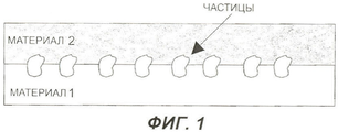
Фиг.1 иллюстрирует концепцию связи на основе механического сцепления с частицами или волокнами на границе раздела двух поверхностей.Figure 1 illustrates the concept of communication based on mechanical adhesion with particles or fibers at the interface between two surfaces.
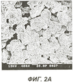
Фиг.2А и В - микрофотографии поверхности частиц стали, декорированных частицами керамики из диоксида циркония, стабилизированного оксидом иттрия, полученные с помощью растрового электронного микроскопа (SEM).2A and B are micrographs of the surface of steel particles decorated with ceramic particles of zirconia stabilized with yttrium oxide obtained using a scanning electron microscope (SEM).
Фиг.3 - схематическая иллюстрация процесса спекания.Figure 3 is a schematic illustration of a sintering process.
Фиг.4А и В - микрофотографии узла соединения между декорированными частицами металла и элементом из плотного YSZ через промежуточный слой из пористого YSZ в разрезе согласно одному примеру осуществления изображения, полученные с помощью SEM.4A and B are micrographs of the junction between the decorated metal particles and the dense YSZ element through an intermediate section of porous YSZ in section according to one embodiment, images obtained using SEM.
Фиг.5 - схематическое изображение узла соединения, представленного на фиг.4А и В.5 is a schematic illustration of the connection node shown in figa and B.
Фиг.6 иллюстрирует стальной токовый коллектор, соединенный с керамикой в твердооксидном топливном элементе в соответствии с одним примером осуществления настоящего изобретения.6 illustrates a steel current collector connected to ceramic in a solid oxide fuel cell in accordance with one embodiment of the present invention.
Подробное описание изобретенияDETAILED DESCRIPTION OF THE INVENTION
Далее подробные ссылки будут делаться на конкретные примеры осуществления изобретения. Примеры конкретных примеров осуществления иллюстрированы прилагаемыми чертежами. Описание изобретения будет вестись применительно к конкретным примерам осуществления, однако очевидно, что это изобретение не ограничено такими конкретными примерами осуществления. Напротив, предполагается, что оно распространяется на варианты, изменения и эквиваленты, которые могут быть включены в изобретение в пределах объема притязаний и эквивалентов прилагаемой формулы изобретения. В приводимом ниже описании рассмотрены многочисленные специальные детали с целью обеспечения полного понимания настоящего изобретения. Настоящее изобретение может быть осуществлено без некоторых или всех этих специальных деталей. В других случаях известные технологические операции не рассматриваются подробно в описании, чтобы не затруднять понимания настоящего изобретения.Detailed references will then be made to specific embodiments of the invention. Examples of specific embodiments are illustrated by the accompanying drawings. The invention will be described in relation to specific embodiments, however, it is obvious that this invention is not limited to such specific embodiments. On the contrary, it is intended to extend to variations, changes and equivalents that may be included in the invention within the scope of the claims and equivalents of the appended claims. In the description below, numerous specific details are set forth in order to provide a thorough understanding of the present invention. The present invention may be practiced without some or all of these special details. In other cases, well-known technological operations are not considered in detail in the description, so as not to impede the understanding of the present invention.
Образование связей, в основе которых лежит механическое сцепление с частицами или волокнами на границе раздела двух поверхностей, является известным фактом. Частицы или волокна могут быть созданы из материала поверхности или привнесены на поверхность в результате плавления или прессования. Однако технологии соединения разнородных материалов типа керамик и металлов, с использованием этой концепции, схематично иллюстрированной на фиг.1, являются неизвестными.The formation of bonds, based on mechanical adhesion with particles or fibers at the interface between two surfaces, is a known fact. Particles or fibers can be created from a surface material or brought to the surface by melting or pressing. However, the joining technology of dissimilar materials such as ceramics and metals, using this concept, schematically illustrated in FIG. 1, is unknown.
Примеры образования связей между разнородными материалами, например, керамика и металлы, в результате спекания также известны. Как правило, из смеси металла и керамических порошков промежуточного слоя формируют ступенчатый узел соединения. Вблизи присоединяемой поверхности керамики смесь промежуточного слоя обогащена керамическим порошком. Вблизи присоединяемой поверхности металла промежуточный слой обогащен металлом. Эту многокомпонентную структуру подвергают спеканию, в результате которого получают две взаимно проникающие решетки: одна отображает связи керамики с керамикой, а другая - металла с металлом. Такие узлы соединения обычно бывают слабыми и толстыми. По толщине узла соединения свойства материалов, как ожидается, будут носить промежуточный характер между свойствами отдельно керамики и отдельно металла. Такое явление может быть нежелательным, особенно в случае, когда для обеспечения эффективности изготавливаемого устройства требуется быстрое изменение свойств материалов в узле соединения на границе раздела. Это имеет место для покрытий теплоизолирующих экранов, где желательно иметь тонкий слой с низким коэффициентом теплопроводности (обычно керамики), покрывающий металлический участок. Это также имеет место для токовых коллекторов топливного элемента, где желательно иметь быстрое изменение размера частиц и механизма электропроводности на границе раздела между металлическим токовым коллектором и активным слоем из керамики. Как правило, узлы соединения с плавно меняющимся профилем обладают низкой пористостью, что не позволяет образовывать прочный узел соединения. Предполагается, что двойное спекание и механическое сцепление, предлагаемое в настоящем изобретении, позволит достичь приемлемой прочности узла соединения в широком диапазоне значений пористости конечного узла соединения и, следовательно, расширить область применения изобретения в отношении узлов соединения с плавно меняющимся профилем.Examples of the formation of bonds between dissimilar materials, for example, ceramics and metals, as a result of sintering are also known. As a rule, a stepped joint assembly is formed from a mixture of metal and ceramic powders of the intermediate layer. Near the joining surface of the ceramic, the intermediate layer mixture is enriched in ceramic powder. Near the joining surface of the metal, the intermediate layer is enriched with metal. This multicomponent structure is subjected to sintering, as a result of which two mutually penetrating lattices are obtained: one reflects the bonds of ceramics with ceramics, and the other - metal-to-metal bonds. Such junction nodes are usually weak and thick. According to the thickness of the joint, the properties of materials are expected to be intermediate between the properties of separately ceramics and separately metal. Such a phenomenon may be undesirable, especially in the case when, to ensure the efficiency of the manufactured device, a quick change in the properties of the materials in the joint at the interface is required. This is the case for coatings of heat-insulating screens, where it is desirable to have a thin layer with a low coefficient of thermal conductivity (usually ceramics) covering the metal area. This also holds true for fuel cell current collectors, where it is desirable to have a rapid change in particle size and electrical conductivity at the interface between the metal current collector and the ceramic active layer. As a rule, connection nodes with a smoothly changing profile have low porosity, which does not allow the formation of a strong connection node. It is assumed that the double sintering and mechanical adhesion proposed in the present invention will achieve acceptable strength of the joint in a wide range of porosity of the final joint and, therefore, to expand the scope of the invention in relation to joints with a smoothly changing profile.
В настоящем изобретении предлагается способ соединения разнородных материалов, имеющих различную пластичность. Способ соединения подходит для соединения разнородных материалов, являющихся химически инертными один к другому (то есть, эффективная химическая связь между этими материалами невозможна) (например, металла и керамики), и позволяет получить прочное сцепление с резкой границей раздела между этими двумя материалами.The present invention provides a method for joining dissimilar materials having different ductility. The joining method is suitable for joining dissimilar materials that are chemically inert to one another (that is, an effective chemical bond between these materials is impossible) (for example, metal and ceramics), and allows for strong adhesion with a sharp interface between the two materials.
Способ включает в себя два основных этапа: декорирование поверхности более пластичного материала частицами менее пластичного материала для создания композита; и связывание созданного композита с присоединяемым элементом менее пластичного материала в результате спекания. Этот способ соединения подходит для соединения разнородных материалов, являющихся химически инертными один к другому (например, металла и керамики), и позволяет получить прочное сцепление с резкой границей раздела между этими двумя материалами.The method includes two main stages: decorating the surface of a more plastic material with particles of a less plastic material to create a composite; and bonding the created composite with a joining element of a less ductile material as a result of sintering. This joining method is suitable for joining dissimilar materials that are chemically inert to one another (for example, metal and ceramics), and allows for strong adhesion with a sharp interface between the two materials.
Соединяемые материалы могут значительно отличаться один от другого по форме или размеру частиц. Например, присоединяемый элемент может быть плотным монолитным куском менее пластичного материала, пористым куском менее пластичного материала или частицами менее пластичного материала. Могут быть сформированы структуры с промежуточными слоями или многослойные структуры. Например, декорированный композит может быть спечен с плотным менее пластичным материалом через промежуточный слой пористого менее пластичного материала.The materials to be bonded can vary significantly from one another in particle shape or size. For example, the attachment member may be a dense monolithic piece of less plastic material, a porous piece of less plastic material, or particles of less plastic material. Interlayer structures or multilayer structures may be formed. For example, a decorated composite may be sintered with a dense less plastic material through an intermediate layer of a porous less plastic material.
Частицы, декорирующие поверхность более пластичного материала, присоединяемый элемент и любые дополнительные элементы могут состоять из одного и того же материала (например, из керамики типа YSZ) или различных материалов, которые спекают один с другим (например, из одной или более керамик и/или керметов типа YSZ и LSM).Particles decorating the surface of a more plastic material, an attachable element, and any additional elements may consist of the same material (for example, ceramics like YSZ) or different materials that sinter one with the other (for example, one or more ceramics and / or cermet type YSZ and LSM).
Ниже приводится описание способа согласно изобретению и соответствующих композитов и устройств со ссылками на частные примеры осуществления, иллюстрированные чертежами. В иллюстративных целях описание изобретения веется в контексте соединения металла (более пластичного материала) и керамики (менее пластичного материала). Однако должно быть очевидно, что изобретение применимо и к другим типам материалов (стеклу, стеклокерамике, полимеру, кермету, полупроводнику и т.д.). Материалы могут находиться в различных геометрических формах типа порошков, волокон или объемных тел (фольги, проволоки, пластины и т.д.).The following is a description of the method according to the invention and the corresponding composites and devices with reference to particular embodiments illustrated by the drawings. For illustrative purposes, the invention is described in the context of the combination of metal (more ductile material) and ceramic (less ductile material). However, it should be obvious that the invention is applicable to other types of materials (glass, glass ceramics, polymer, cermet, semiconductor, etc.). Materials can be in various geometric forms such as powders, fibers or bulk bodies (foils, wires, plates, etc.).
Этап 1. Декорирование пластичной поверхности частицами менее пластичного материала.Step 1. Decorating the plastic surface with particles of less plastic material.
"Декорирование" следует понимать как процесс механического внедрения, импрегнирования, вдавливания или загонки менее пластичного материала в поверхность более пластичного материала или связывания этих поверхностей каким-либо другим способом. "Пластичность" - это, вообще говоря, способность материала деформироваться под действием силы растяжения. Например, поверхность металлического тела или частицы может быть декорирована частицами керамик путем вдавливания керамики в поверхность металла. При этом металл будет деформироваться вокруг частицы керамики и трение, напряжение и/или механическое сцепление будет препятствовать простому удалению частицы керамики с поверхности металлической поверхности.“Decoration” should be understood as the process of mechanically introducing, impregnating, pushing or folding a less ductile material into the surface of a more ductile material or bonding these surfaces in some other way. "Plasticity" is, generally speaking, the ability of a material to deform under the action of tensile forces. For example, the surface of a metal body or particle can be decorated with ceramic particles by pressing ceramic into the metal surface. In this case, the metal will deform around the ceramic particle and friction, stress and / or mechanical adhesion will prevent the simple removal of the ceramic particle from the surface of the metal surface.
На фиг.2А и В представлены микрофотографии поверхности частиц стали, декорированных частицами керамики из диоксида циркония, стабилизированного оксидом иттрия, полученные с помощью растрового электронного микроскопа (SEM), с малым и большим увеличениями.On figa and b presents micrographs of the surface of the particles of steel, decorated with ceramic particles of zirconia stabilized with yttrium oxide, obtained using a scanning electron microscope (SEM), with small and large magnifications.
В этом случае два типа частиц были подвергнуты совместному смешиванию в мельнице в присутствии изопропилового спирта (IPA). В смесь было добавлено связующее (гидроксипропилцеллюлоза, НРС) для образования агломератов YSZ на поверхности частиц металла. Такие агломераты улучшаются связывание путем спекания, достигаемое на этапе 2. Под действием сдвигающего усилия мельницы частицы YSZ загоняются в поверхность частиц металла и остаются внедренными в поверхности после дробления.In this case, two types of particles were co-mixed in a mill in the presence of isopropyl alcohol (IPA). A binder (hydroxypropyl cellulose, LDC) was added to the mixture to form YSZ agglomerates on the surface of the metal particles. Such agglomerates improve bonding by sintering, achieved in step 2. Under the action of the shear force of the mill, the YSZ particles are driven into the surface of the metal particles and remain embedded in the surface after crushing.
В альтернативных примерах осуществления декорирование может быть достигнуто с помощью дополнительных методов, таких как химическое связывание декорирующего материала с поверхностью через связующий агент или расплавление поверхности для приживления декорирующего материала.In alternative embodiments, decorating can be achieved using additional methods, such as chemically bonding the decorating material to the surface via a bonding agent or melting the surface to engraft the decorating material.
Этап 2. Связывания композита, созданного на этапе 1, с присоединяемым элементом менее пластичного материала в результате спекания.Stage 2. The bonding of the composite created in stage 1, with the attached element of less plastic material as a result of sintering.
Спекание часто используется для соединения частиц однородных материалов. Процесс спекания заключается в формировании шеек между соседними частицами. Движущей силой этого процесса является уменьшение площади поверхности/ поверхностного натяжения. На фиг.3 представлена схематическая иллюстрация процесса спекания. Способ связывания путем спекания может быть использован для соединения частиц декорированного композита с менее пластичной поверхностью с элементом менее пластичного материала. Степень спекания можно контролировать так, что соединяемые материалы оставались пористыми или становились плотными.Sintering is often used to join particles of homogeneous materials. The sintering process consists in the formation of necks between adjacent particles. The driving force behind this process is the reduction in surface area / surface tension. Figure 3 presents a schematic illustration of the sintering process. The sinter bonding method can be used to connect the particles of a decorated composite with a less plastic surface with an element of a less plastic material. The degree of sintering can be controlled so that the materials to be joined remain porous or become dense.
В некоторых примерах осуществления присоединяемый элемент может быть промежуточным слоем, используемым между спекаемыми материалами. Например, частицы металла, декорированные YSZ описанным выше способом, могут быть соединены с плотным элементом из YSZ посредством промежуточного слоя YSZ в виде макрочастицы. Промежуточный слой способствует образованию прочной связи между декорированными частицами и слоем плотного YSZ. Разумеется, композит может быть также подвергнут связыванию путем спекания непосредственно через декорированные частицы на своей поверхности с плотной поверхностью без использования промежуточного слоя или с пористой поверхностью или материалом макрочастицы без использования плотного элемента.In some embodiments, the attachment member may be an intermediate layer used between the sintered materials. For example, metal particles decorated with YSZ as described above can be connected to a dense element of YSZ via an intermediate layer of YSZ in the form of a particulate. The intermediate layer promotes the formation of a strong bond between the decorated particles and the dense YSZ layer. Of course, the composite can also be bonded by sintering directly through the decorated particles on its surface with a dense surface without using an intermediate layer or with a porous surface or particulate material without using a dense element.
В некоторых случаях частицы металла могут подвергаться спеканию между металлом и металлом. Для соединения частиц металла с элементом из YSZ этого не требуется, однако такая потребность возникает при необходимости создания низкоомного канала для прохождения электронов через пористый металл, и поэтому процесс такого спекания является желательным для токового коллектора твердооксидного топливного элемента (SOFC). В областях использования этого изобретения, не связанных с SOFC, необходимости в процессе спекания металла с металлом может не возникать.In some cases, the metal particles may undergo sintering between the metal and the metal. This is not required to connect metal particles with a YSZ element, however, such a need arises when it is necessary to create a low-resistance channel for the passage of electrons through a porous metal, and therefore a sintering process is desirable for a solid oxide fuel cell (SOFC) current collector. In areas of use of this invention that are not related to SOFC, the need for a sintering process of metal with metal may not arise.
На фиг.4А и В представлены микрофотографии узла соединения между декорированными частицами металла и элементом из плотного YSZ через промежуточный слой из пористого YSZ в разрезе, полученные с помощью SEM. Образующиеся в процессе спекания связи существуют: между отдельными частицами металла; между декорирующим YSZ и пористым промежуточным слоем спеченных частиц YSZ; а также между пористым промежуточным слоем спеченных частиц YSZ и элементом из плотного YSZ.Figures 4A and B are micrographs of the junction between the decorated metal particles and the dense YSZ element through an intermediate section of porous YSZ in section, obtained using SEM. The bonds formed during the sintering process exist: between individual metal particles; between the decorating YSZ and the porous intermediate layer of sintered YSZ particles; and also between the porous intermediate layer of sintered YSZ particles and the dense YSZ element.
На фиг.5 представлено схематическое изображение узла соединения, показанного на фиг.4А и В, иллюстрирующее способ соединения согласно настоящему изобретению для этого конкретного примера осуществления. Конечно, пористый промежуточный слой является необязательным, в других примерах осуществления материал декорированного металла может быть подвергнут непосредственному связыванию с плотной керамикой или керметом.FIG. 5 is a schematic illustration of the connection assembly shown in FIGS. 4A and B illustrating a connection method according to the present invention for this particular embodiment. Of course, a porous intermediate layer is optional, in other embodiments, the material of the decorated metal can be directly bonded to a dense ceramic or cermet.
Таким образом, один объект изобретения касается способа соединения разнородных материалов, имеющих различную пластичность. Способ заключается в декорировании поверхности более пластичного материала частицами менее пластичного материала для создания композита и связывании созданного композита с присоединяемым элементом менее пластичного материала в результате спекания. Способ соединения подходит для соединения разнородных материалов, являющихся химически инертными один относительно другого (например, металла и керамики) и позволяет получить прочное сцепление с резкой границей раздела между этими двумя материалами. В процессе декорирования в смесь может быть добавлено связующее типа гидроксипропилцеллюлозы для образования агломератов декорирующего материала на поверхности декорируемого материала и улучшения связывания при спекании.Thus, one object of the invention relates to a method for joining dissimilar materials having different ductility. The method consists in decorating the surface of a more plastic material with particles of a less plastic material to create a composite and bonding the created composite with an attached element of a less plastic material as a result of sintering. The joining method is suitable for joining dissimilar materials that are chemically inert with respect to one another (for example, metal and ceramics) and allows for strong adhesion with a sharp interface between the two materials. During the decoration process, a binder such as hydroxypropyl cellulose can be added to the mixture to form agglomerates of the decoration material on the surface of the decoration material and to improve sintering bonding.
Декорирование, как правило, обеспечивает нанесение покрытия на часть декорируемой поверхности, например приблизительно 10-80% площади поверхности более пластичного материала декорируется менее пластичным материалом. В некоторых частных случаях площадь покрываемой поверхности составляет 30-60%, приблизительно 50% или приблизительно 20-30%.Decoration typically provides a coating on a portion of the surface to be decorated, for example about 10-80% of the surface area of a more plastic material is decorated with a less plastic material. In some particular cases, the surface area to be coated is 30-60%, approximately 50%, or approximately 20-30%.
В различных примерах осуществления размер частиц декорирующих частиц перед спеканием составляет приблизительно 10-0,05 мкм, например 0,5 мкм. В частном примере осуществления изобретение используют для соединения металла, в частности Fe, Ni, Cu, Ag, Al, Ti, сплавов, содержащих Ni, сплавов, содержащих Cu, сплавов, содержащих Ar, сплавы, содержащие Al, сплавы, содержащие Ti, хромсодержащих сплавов на основе Ni или Fe или нержавеющей стали (ферросплава с минимальным содержанием Cr, составляющим 10,5%), и керамики, в частности YSZ.In various embodiments, the particle size of the decorating particles before sintering is about 10-0.05 microns, for example 0.5 microns. In a particular embodiment, the invention is used to combine metal, in particular Fe, Ni, Cu, Ag, Al, Ti, alloys containing Ni, alloys containing Cu, alloys containing Ar, alloys containing Al, alloys containing Ti, chromium-containing alloys based on Ni or Fe or stainless steel (ferroalloy with a minimum Cr content of 10.5%), and ceramics, in particular YSZ.
Во многих примерах осуществления материал керамики обладает исключительно ионной проводимостью (например, YSZ), но в других примерах осуществления один или более материалов керамики могут быть смешанным ионно-электронным проводником (например, LSM, оксид церия и т.д.). Среди подходящих керамических компонентов можно назвать: La1-xSrxMnyO3-δ (1≥X≥0,05) (0,95≤у≤1,15) ("LSM") (δ определяется как значение, выражающее малое отклонение от точной стехиометрии) (например, La0,8Sr0,2MnO3 и La0,65Sr0,30MnO3-δ и La0,45Sr0,55MnO3-δ); La1-xSrxCoO3-δ. (1≥Х≥0,10) ("LSC"), La1-xSrxFeyO3-δ (1≥X≥0,05) (0,95≤y≤1,15) ("LSF"), SrCo1-xFexO3-δ (0,30≥X≥0,20), La0,6Sr0,4Co0,6Fe0,4O3-δ, Sr0,7Ce0,3MnO3-δ, LaNi0,6Fe0,4O3-δ, Sm0,5Sr0,5CoO3-δ, диоксид циркония, стабилизированный оксидом иттрия (YSZ), диоксид циркония, стабилизированный оксидом скандия (SSZ), (CeO2)0,8(Gd2O3)0,2 (CGO), LaO0,8Sr0,2Ga0,85Mg0,15O2,825 (LSGM20-15), (Bi2O3)0,75(Y2O3)0,25, оксид алюминия и оксид церия.In many embodiments, the ceramic material has exclusively ionic conductivity (e.g., YSZ), but in other embodiments, one or more ceramic materials may be a mixed ion-electron conductor (e.g., LSM, cerium oxide, etc.). Suitable ceramic components include: La 1-x Sr x Mn y O 3-δ (1≥X≥0.05) (0.95≤y≤1.15) ("LSM") (δ is defined as the value expressing a small deviation from accurate stoichiometry) (for example, La 0.8 Sr 0.2 MnO 3 and La 0.65 Sr 0.30 MnO 3-δ and La 0.45 Sr 0.55 MnO 3-δ ); La 1-x Sr x CoO 3-δ . (1≥X≥0.10) ("LSC"), La 1-x Sr x Fe y O 3-δ (1≥X≥0.05) (0.95≤y≤1.15) ("LSF "), SrCo 1-x Fe x O 3-δ (0.30≥X≥0.20), La 0.6 Sr 0.4 Co 0.6 Fe 0.4 O 3-δ , Sr 0.7 Ce 0.3 MnO 3-δ , LaNi 0.6 Fe 0.4 O 3-δ , Sm 0.5 Sr 0.5 CoO 3-δ , zirconia stabilized with yttrium oxide (YSZ), zirconia stabilized with oxide scandium (SSZ), (CeO 2 ) 0.8 (Gd 2 O 3 ) 0.2 (CGO), LaO 0.8 Sr 0.2 Ga 0.85 Mg 0.15 O 2.825 (LSGM20-15), ( Bi 2 O 3 ) 0.75 (Y 2 O 3 ) 0.25 , alumina and cerium oxide.
Подходящие металлические компоненты, в том числе для керметов, являются переходными металлами, Cr, Fe, Ag и/или сплавами, такими как нержавеющие стали; ферритные стали с низким содержанием хрома типа 405 и 409 (с 11-15% Cr), ферритные стали с промежуточным содержанием хрома типа 430 и 434 (с 16-18% Cr), высокохромистые ферритные стали типа 442, 446 и E-Brite (с 19-30% Cr), сплавы на основе хрома типа Cr5Fe1Y и хромсодержащие сплавы на основе никеля типа Ni20Cr и сплавы Inconel, в том числе Inconel 600 (с 76% Ni, 15,5% Cr, 8% Fe, 0,2% Cu, 0,2% Si, 0,5% Mn и 0,08% С).Suitable metal components, including for cermets, are transition metals, Cr, Fe, Ag and / or alloys, such as stainless steels; ferritic steels with a low chromium content of types 405 and 409 (with 11-15% Cr), ferritic steels with an intermediate chromium content of types 430 and 434 (with 16-18% Cr), high-chromium ferritic steels of type 442, 446 and E-Brite ( with 19-30% Cr), chromium-based alloys of the Cr5Fe1Y type and chromium-containing nickel-based alloys of the Ni20Cr type and Inconel alloys, including Inconel 600 (with 76% Ni, 15.5% Cr, 8% Fe, 0.2 % Cu, 0.2% Si, 0.5% Mn and 0.08% C).
В изобретении используется разность механических свойств соединяемых материалов, а также способность менее пластичного материала к спеканию, а не какое-либо химическое взаимодействие между материалами. Изобретение позволяет создать узел соединения в течение относительно короткого промежутка времени без введения дополнительных необходимых материалов и обеспечивает получение прочного сцепления с резкой границей раздела между этими двумя материалами.The invention uses the difference in the mechanical properties of the materials to be joined, as well as the ability of the less plastic material to sinter, rather than any chemical interaction between the materials. The invention allows to create a connection node for a relatively short period of time without introducing additional necessary materials and provides strong adhesion with a sharp interface between these two materials.
Технология согласно настоящему изобретению может быть использована в производстве твердооксидных топливных элементов и соответствующих электрохимических устройств. Металлические токовые коллекторы обычно соединяют с твердооксидными топливными элементами путем пайки мягким припоем, пайки твердым припоем или простым механическим прессованием (без связывания). В настоящем изобретении для соединения металлического токового коллектора с керамикой в твердооксидном топливном элементе предлагается способ более надежного связывания токового коллектора и ячейки без введения мягкого припоя или твердого припоя. В частном примере реализации, иллюстрируемом на фиг.6. токовый коллектор из пористого металла (например, из нержавеющей стали) декорируют частицами керамики (YSZ) описываемым в данном документе способом для образования композита. Композит соединяют с подложкой из плотной керамики (YSZ) через промежуточный слой пористого YSZ.The technology of the present invention can be used in the manufacture of solid oxide fuel cells and related electrochemical devices. Metal current collectors are usually connected to solid oxide fuel cells by brazing, brazing, or simple mechanical pressing (without bonding). The present invention provides a method for more securely bonding a current collector and a cell without introducing soft solder or hard solder to connect the metal current collector to ceramic in a solid oxide fuel cell. In a particular example implementation, illustrated in Fig.6. a porous metal current collector (e.g., stainless steel) is decorated with ceramic particles (YSZ) as described herein to form a composite. The composite is bonded to a dense ceramic substrate (YSZ) through an intermediate layer of porous YSZ.
Помимо применения в твердооксидных топливных элементах для получения соединения металлов и керамик изобретение может быть использовано в других областях и применительно к другим группам материалов, в том числе к стеклу, стеклокерамике, полимеру, кермету, полупроводнику и т.д. В некоторых других областях применения изобретение может быть использовано для обеспечения:In addition to the use in solid oxide fuel cells for the production of metal and ceramic compounds, the invention can be used in other fields and in relation to other groups of materials, including glass, glass ceramics, polymer, cermet, semiconductor, etc. In some other applications, the invention can be used to provide:
1. связывания металлических токовых коллекторов с керамиками в топливном элементе или другом электрохимическом устройстве;1. linking metal current collectors with ceramics in a fuel cell or other electrochemical device;
2. связывания слоев теплоизолирующих экранов с участками металла для использования в высокотемпературных технологиях (в области газовых турбин, ракетных двигателей и т.д.);2. linking layers of heat-insulating screens with metal areas for use in high-temperature technologies (in the field of gas turbines, rocket engines, etc.);
3. связывания износостойких слоев с участками металла (в области машиностроения, производства медицинских имплантатов, клюшек для игры в гольф и т.д.);3. binding of wear-resistant layers to metal areas (in the field of mechanical engineering, the production of medical implants, golf clubs, etc.);
4. связывания электродов с обкладками конденсаторов;4. binding of electrodes to capacitor plates;
5. модифицирования поверхности металла или пластичного материала для придания ему большей абразивности, стойкости к коррозии, более высоких изоляционных свойств и т.д.;5. modifying the surface of the metal or plastic material to give it greater abrasion, corrosion resistance, higher insulating properties, etc .;
6. модифицирования поверхности керамики или менее пластичного материала для снижения его абразивности, придания более высокой пластичности, более высокой электропроводности, более высокой отражательной способности и т.д.;6. modifying the surface of the ceramic or less ductile material to reduce its abrasiveness, imparting higher ductility, higher electrical conductivity, higher reflectivity, etc .;
7. получения декоративных эффектов на металлической подложке с помощью керамики или наоборот.7. receiving decorative effects on a metal substrate using ceramics or vice versa.
Другой объект изобретения касается композита из разнородных материалов, имеющих различную пластичность, и электрохимических устройств, включающих в себя такой композит. Композит имеет более пластичный материал, менее пластичный материал и границу раздела между более и менее пластичными материалами, содержащую частицы менее пластичного материала, декорированного на поверхность более пластичного материала, спеченного с менее пластичным материалом.Another object of the invention relates to a composite of dissimilar materials having different ductility, and electrochemical devices including such a composite. The composite has a more plastic material, a less plastic material and an interface between more and less plastic materials containing particles of a less plastic material decorated on the surface of a more plastic material sintered with a less plastic material.
ПримерExample
Приводимый ниже пример описывает и иллюстрирует особенности и признаки частной реализации настоящего изобретения. Должно быть понятно, что рассматриваемые особенности и признаки следует рассматривать исключительно как характерные, и что изобретение не ограничено деталями, описываемыми в этом примере.The following example describes and illustrates features and features of a private implementation of the present invention. It should be understood that the features and features considered should be considered solely characteristic, and that the invention is not limited to the details described in this example.
Связывание стального токового коллектора со структурой твердооксидного топливного элементаLinking a steel current collector to a solid oxide fuel cell structure
Как указано выше, на фиг.2 представлена поверхность изделия из ферритной нержавеющей стали 70Fe-30Cr, декорированная частицами диоксида циркония, стабилизированного оксидом иттрия (YSZ). YSZ является стандартным материалом электролита для твердооксидных топливных элементов. Два типа частиц были подвергнуты совместному смешиванию в мельнице в присутствии изопропилового спирта (IPA). В смесь было добавлено связующее (гидроксипропилцеллюлоза, НРС) для образования агломератов YSZ на поверхности частиц металла. Под действием сдвигающих усилий мельницы частицы YSZ были загнаны в поверхность частиц металла, где они остались внедренными после дробления. Частицы металла, декорированные YSZ, были соединены одна с другой (спеканием металла с металлом) и с элементом из плотного YSZ посредством промежуточного слоя YSZ в виде макрочастицы в результате спекания, и было получено прочное сцепление с резкой границей раздела между этими двумя материалами. На фиг.4А и В представлены микрофотографии узла соединения между декорированными частицами металла и элементом из плотного YSZ в разрезе. Связывание элементов узла соединения в результате спекания было осуществлено путем совместного обжига в атмосфере 4% Н2/ 96% Ar в течение 4 часов при 1300°С. Образующиеся в процессе спекания связи существуют: между отдельными частицами металла; между декорирующим YSZ и спеченными частицами YSZ; а также между спеченными частицами YSZ и элементом из плотного YSZ. Для сравнения, физические смеси YSZ и частиц металла были подвергнуты спеканию на подложках из подобного плотного YSZ при наличии и без промежуточного слоя из пористого YSZ, и в результате была получена слабая связь или полное отсутствие связи. Таким образом, этап декорирования следует рассматривать как критический для получения качественного сцепления металла и керамики.As indicated above, figure 2 presents the surface of the product of ferritic stainless steel 70Fe-30Cr, decorated with particles of zirconia stabilized with yttrium oxide (YSZ). YSZ is the standard electrolyte material for solid oxide fuel cells. Two types of particles were co-mixed in a mill in the presence of isopropyl alcohol (IPA). A binder (hydroxypropyl cellulose, LDC) was added to the mixture to form YSZ agglomerates on the surface of the metal particles. Under the action of the shear forces of the mill, the YSZ particles were driven into the surface of the metal particles, where they remained embedded after crushing. The metal particles decorated with YSZ were bonded to each other (sintering metal to metal) and to an element made of dense YSZ by means of an intermediate layer of YSZ as a particulate as a result of sintering, and strong adhesion was obtained with a sharp interface between the two materials. Figures 4A and B are micrographs of the junction between the decorated metal particles and a sectional view of a dense YSZ element. The bonding of the elements of the connection node as a result of sintering was carried out by co-firing in an atmosphere of 4% H 2 /96% Ar for 4 hours at 1300 ° C. The bonds formed during the sintering process exist: between individual metal particles; between decorating YSZ and sintered particles of YSZ; as well as between the sintered YSZ particles and the dense YSZ element. For comparison, physical mixtures of YSZ and metal particles were sintered on substrates of a similar dense YSZ with and without an intermediate layer of porous YSZ, and as a result, a weak bond or a complete lack of bond was obtained. Thus, the decoration step should be considered critical for obtaining high-quality adhesion of metal and ceramics.
Улучшенное сцепление было достигнуто с использованием самых различных частиц YSZ в качестве декорирующего YSZ. Лучшие связи были получены при использовании субмикронных частиц YSZ (диаметром приблизительно 0,5 мкм), однако декорирование частицами и волокнами с размерами до 10 мкм также способствовала улучшению сцепления. Концентрации YSZ во время этапа декорирования варьировались в диапазоне, соответствующем массовому соотношению между YSZ и металлом 1:99-4:96. Хорошее сцепление было выявлено по всему этому диапазону, причем наиболее сильное сцепление было получено при соотношении 4:96. Изучение более высоких концентраций YSZ не проводилось, так как при соотношении 4:96 наблюдается насыщение поверхности металла YSZ с некоторым избытком YSZ, заполняющим поры между декорированными частицами металла. Этот избыточный YSZ блокирует транспорт газа при работе топливного элемента и поэтому является нежелательным в этой области применения. В других областях применения изобретения наличие открытой пористой структуры может быть необязательным, и допустимы более высокие концентрации декорирующего материала.Improved grip has been achieved using a wide variety of YSZ particles as decorating YSZ. The best bonds were obtained using YSZ submicron particles (with a diameter of approximately 0.5 μm), however, decorating with particles and fibers with sizes up to 10 μm also contributed to improved adhesion. The concentration of YSZ during the decorating phase varied in the range corresponding to the mass ratio between YSZ and the metal 1: 99-4: 96. Good adhesion was found throughout this range, with the strongest adhesion obtained at a ratio of 4:96. A study of higher concentrations of YSZ was not carried out, since at a ratio of 4:96 saturation of the YSZ metal surface is observed with some excess YSZ filling the pores between the decorated metal particles. This excess YSZ blocks gas transport during fuel cell operation and is therefore undesirable in this application. In other fields of application of the invention, the presence of an open porous structure may be optional, and higher concentrations of decorating material are acceptable.
ЗаключениеConclusion
Таким образом, изобретение охватывает способ соединения путем декорирования/спекания, который может быть использован применительно к разнородным материалам, имеющим различную пластичность, и обеспечивает получение прочного сцепления с резкой границей раздела между этими двумя материалами. Предлагаются также композиты и устройства с декорированной/спеченной поверхностью раздела.Thus, the invention encompasses a bonding method by decoration / sintering, which can be used with dissimilar materials having different ductility, and provides a strong bond with a sharp interface between the two materials. Composites and devices with a decorated / sintered interface are also available.
Выше было приведено подробное описание изобретения в целях обеспечения ясности его понимания, однако очевидно, что в него могут быть внесены определенные изменения и дополнения, не выходящие за пределы объема притязаний прилагаемой формулы изобретения. Следует отметить то, что существует множество альтернативных способов реализации как технологии, таки и составов согласно настоящему изобретению. Следовательно, приведенные примеры осуществления нужно рассматривать как иллюстративные, а не ограничительные, и изобретение не должно быть ограничено приведенными в данном документе деталями.The above was a detailed description of the invention in order to ensure clarity of its understanding, however, it is obvious that certain changes and additions can be made to it, not going beyond the scope of the claims of the attached claims. It should be noted that there are many alternative ways of implementing both the technology and the compositions according to the present invention. Therefore, the examples of implementation should be considered as illustrative and not restrictive, and the invention should not be limited to the details given in this document.
Все документы, цитируемые в данном документе, включены в качестве ссылки для всех целей.All documents cited in this document are incorporated by reference for all purposes.
Claims (31)
Applications Claiming Priority (2)
| Application Number | Priority Date | Filing Date | Title |
|---|---|---|---|
| US63203004P | 2004-11-30 | 2004-11-30 | |
| US60/632,030 | 2004-11-30 |
Publications (2)
| Publication Number | Publication Date |
|---|---|
| RU2007124484A RU2007124484A (en) | 2009-01-10 |
| RU2406591C2 true RU2406591C2 (en) | 2010-12-20 |
Family
ID=36927870
Family Applications (1)
| Application Number | Title | Priority Date | Filing Date |
|---|---|---|---|
| RU2007124484A RU2406591C2 (en) | 2004-11-30 | 2005-11-29 | Jointing diverse materials |
Country Status (7)
| Country | Link |
|---|---|
| US (1) | US8287673B2 (en) |
| EP (1) | EP1829112A4 (en) |
| AU (1) | AU2005327925B2 (en) |
| CA (1) | CA2630526A1 (en) |
| NO (1) | NO20073304L (en) |
| RU (1) | RU2406591C2 (en) |
| WO (1) | WO2006091250A2 (en) |
Cited By (3)
| Publication number | Priority date | Publication date | Assignee | Title |
|---|---|---|---|---|
| RU2574549C2 (en) * | 2013-04-12 | 2016-02-10 | Альстом Текнолоджи Лтд | Structure for joining of heat-insulating material with metal structure |
| US9764530B2 (en) | 2013-04-12 | 2017-09-19 | Ansaldo Energia Ip Uk Limited | Method for obtaining a configuration for joining a ceramic material to a metallic structure |
| RU2687342C2 (en) * | 2015-05-04 | 2019-05-13 | Те Свотч Груп Рисерч Энд Дивелопмент Лтд | Method of installing decorative element on base and said base |
Families Citing this family (17)
| Publication number | Priority date | Publication date | Assignee | Title |
|---|---|---|---|---|
| US6605316B1 (en) | 1999-07-31 | 2003-08-12 | The Regents Of The University Of California | Structures and fabrication techniques for solid state electrochemical devices |
| EP1825541A4 (en) | 2004-11-30 | 2010-01-13 | Univ California | Sealed joint structure for electrochemical device |
| CA2627786C (en) * | 2004-11-30 | 2012-03-27 | The Regents Of The University Of California | Braze system with matched coefficients of thermal expansion |
| EP1829112A4 (en) | 2004-11-30 | 2009-11-18 | Univ California | Joining of dissimilar materials |
| CA2647528A1 (en) * | 2006-03-30 | 2007-11-08 | Rhodia Inc. | Modified surfaces and method for modifying a surface |
| CN101507352B (en) * | 2006-07-28 | 2013-09-18 | 加州大学评议会 | Joined concentric tubes |
| US20080217382A1 (en) * | 2007-03-07 | 2008-09-11 | Battelle Memorial Institute | Metal-ceramic composite air braze with ceramic particulate |
| KR20100065296A (en) * | 2007-07-25 | 2010-06-16 | 더 리전트 오브 더 유니버시티 오브 캘리포니아 | High temperature electrochemical device with interlocking structure |
| US7989068B2 (en) * | 2007-11-06 | 2011-08-02 | Rhodia Operations | Articles having an interface between a polymer surface and a modified glass surface |
| ATE540133T1 (en) * | 2008-02-04 | 2012-01-15 | Univ California | CU-BASED CERMET FOR HIGH TEMPERATURE FUEL CELLS |
| MY147805A (en) | 2008-04-18 | 2013-01-31 | Univ California | Integrated seal for high-temperature electrochemical device |
| US20110111309A1 (en) * | 2009-11-10 | 2011-05-12 | Point Source Power, Inc. | Fuel cell system |
| US9855548B2 (en) | 2010-11-09 | 2018-01-02 | Sienna Technologies, Inc. | High temperature catalysts for decomposition of liquid monopropellants and methods for producing the same |
| US20120148769A1 (en) * | 2010-12-13 | 2012-06-14 | General Electric Company | Method of fabricating a component using a two-layer structural coating |
| US9149795B2 (en) * | 2011-05-25 | 2015-10-06 | Sienna Technologies, Inc. | Corrosion resistant catalysts for decomposition of liquid monopropellants |
| CN104080285B (en) * | 2013-03-25 | 2017-07-14 | 华为技术有限公司 | A kind of ceramic shell structural member and preparation method thereof |
| US11701802B2 (en) | 2019-11-05 | 2023-07-18 | GM Global Technology Operations LLC | Enthalpy-driven self-hardening process at the polymeric/metal layer interface with an interdiffusion process |
Family Cites Families (108)
| Publication number | Priority date | Publication date | Assignee | Title |
|---|---|---|---|---|
| US3126311A (en) * | 1964-03-24 | Laminated plastic article and method wherein | ||
| US3324543A (en) * | 1965-03-26 | 1967-06-13 | Charles I Mcvey | Pressure bonded ceramic-to-metal gradient seals |
| FR1585403A (en) | 1968-04-19 | 1970-01-23 | ||
| ZA702110B (en) | 1969-04-18 | 1971-11-24 | Nat Standard Co | Metal bonding |
| BE749879A (en) * | 1969-05-16 | 1970-11-04 | Comp Generale Electricite | HIGH TEMPERATURE BATTERIES AND FUEL CELL BATTERIES |
| US4035547A (en) * | 1974-02-26 | 1977-07-12 | William C. Heller | Bonding element having separate heating and agitating particles |
| JPS5915960A (en) | 1982-07-19 | 1984-01-27 | Konishiroku Photo Ind Co Ltd | Thermal fixation device |
| JPS5916695A (en) | 1982-07-20 | 1984-01-27 | Toyota Motor Corp | Filler metal containing ceramic fiber |
| JPS59232693A (en) * | 1983-06-17 | 1984-12-27 | Ngk Spark Plug Co Ltd | Clad brazing filler metal for joining ceramics and metal or the like and composite body composed of ceramics and metal or the like using said brazing filler metal |
| JPS6090875A (en) * | 1983-10-21 | 1985-05-22 | 三菱重工業株式会社 | Ceramic and matal bonding method |
| GB8332639D0 (en) * | 1983-12-07 | 1984-01-11 | Atomic Energy Authority Uk | Steel:ceramic seals |
| JPS60131875A (en) * | 1983-12-20 | 1985-07-13 | 三菱重工業株式会社 | Method of bonding ceramic and metal |
| US4560607A (en) * | 1984-06-07 | 1985-12-24 | The Duriron Company, Inc. | Method of joining materials by mechanical interlock and article |
| JPS61158839A (en) * | 1984-12-28 | 1986-07-18 | Okuno Seiyaku Kogyo Kk | Glass composition |
| US4687717A (en) * | 1986-07-08 | 1987-08-18 | The United States Of America As Represent By The United States Department Of Energy | Bipolar battery with array of sealed cells |
| EP0261343A3 (en) * | 1986-08-23 | 1989-04-26 | Blome GmbH & Co. Kommanditgesellschaft | Method of making profiling projections on steel objects coated with synthetic resins, and coated steel objects obtained |
| SU1407675A1 (en) | 1987-01-19 | 1988-07-07 | Предприятие П/Я В-8402 | Method of compacting composite articles from powder |
| US4942999A (en) * | 1987-08-31 | 1990-07-24 | Ngk Insulators, Inc. | Metal-ceramic joined composite bodies and joining process therefor |
| US4847172A (en) * | 1988-02-22 | 1989-07-11 | Westinghouse Electric Corp. | Low resistance fuel electrodes |
| US5013612A (en) | 1989-11-13 | 1991-05-07 | Ford Motor Company | Braze material for joining ceramic to metal and ceramic to ceramic surfaces and joined ceramic to metal and ceramic to ceramic article |
| US5127969A (en) * | 1990-03-22 | 1992-07-07 | University Of Cincinnati | Reinforced solder, brazing and welding compositions and methods for preparation thereof |
| US5043229A (en) * | 1990-06-14 | 1991-08-27 | Gte Products Corporation | Brazed ceramic-metal composite |
| US5236787A (en) * | 1991-07-29 | 1993-08-17 | Caterpillar Inc. | Thermal barrier coating for metallic components |
| JPH0589883A (en) | 1991-09-25 | 1993-04-09 | Tokyo Gas Co Ltd | Method for forming fuel electrode of solid electrolyte type fuel cell |
| US5329103A (en) * | 1991-10-30 | 1994-07-12 | Spectra-Physics | Laser beam scanner with low cost ditherer mechanism |
| JPH05163078A (en) | 1991-12-18 | 1993-06-29 | Nippon Steel Corp | Joint form made up of ceramic and metal |
| US5338623A (en) | 1992-02-28 | 1994-08-16 | Ceramatec, Inc. | Series tubular design for solid electrolyte oxygen pump |
| US5279909A (en) * | 1992-05-01 | 1994-01-18 | General Atomics | Compact multilayer ceramic-to-metal seal structure |
| US5626914A (en) * | 1992-09-17 | 1997-05-06 | Coors Ceramics Company | Ceramic-metal composites |
| US5735332A (en) * | 1992-09-17 | 1998-04-07 | Coors Ceramics Company | Method for making a ceramic metal composite |
| DE4314323C2 (en) | 1993-04-30 | 1998-01-22 | Siemens Ag | High-temperature fuel cell with an improved solid electrolyte / electrode interface and method for producing a multilayer structure with an improved solid electrolyte / electrode interface |
| EP0700337B1 (en) * | 1993-05-25 | 2002-11-20 | Lord Corporation | Method for obtaining mechanical lock between surfaces |
| JPH0769749A (en) | 1993-09-03 | 1995-03-14 | Tanaka Kikinzoku Kogyo Kk | Brazing material for ceramic |
| JP3100295B2 (en) | 1993-09-27 | 2000-10-16 | 三菱重工業株式会社 | Joining method of solid electrolyte made of ceramic material |
| JP3495770B2 (en) | 1993-10-29 | 2004-02-09 | 日本発条株式会社 | Brazing filler metal for ceramics |
| JPH07202063A (en) * | 1993-12-28 | 1995-08-04 | Toshiba Corp | Ceramic circuit board |
| US5441825A (en) * | 1994-01-24 | 1995-08-15 | Westinghouse Electric Corporation | Battery electrode compression mechanism |
| JP3276509B2 (en) | 1994-03-24 | 2002-04-22 | 太平洋セメント株式会社 | Joining method of ceramics and metal |
| JP3896432B2 (en) | 1995-11-08 | 2007-03-22 | Dowaメタルテック株式会社 | Method for producing metal-ceramic composite substrate and brazing material used therefor |
| US5753385A (en) * | 1995-12-12 | 1998-05-19 | Regents Of The University Of California | Hybrid deposition of thin film solid oxide fuel cells and electrolyzers |
| JP3689970B2 (en) | 1996-04-30 | 2005-08-31 | 日産自動車株式会社 | Manufacturing method of composite sintered joint |
| JPH1021931A (en) | 1996-06-27 | 1998-01-23 | Kyocera Corp | Solid electrolyte type fuel cell |
| US6296910B1 (en) * | 1997-05-29 | 2001-10-02 | Imperial College Of Science, Technology & Medicine | Film or coating deposition on a substrate |
| US6200541B1 (en) * | 1997-10-28 | 2001-03-13 | Bp Amoco Corporation | Composite materials for membrane reactors |
| JP3315919B2 (en) * | 1998-02-18 | 2002-08-19 | 日本碍子株式会社 | Method for manufacturing a composite member composed of two or more different types of members |
| JPH11297333A (en) | 1998-04-03 | 1999-10-29 | Kansai Electric Power Co Inc:The | Fuel electrode and solid electrolyte fuel cell using the same |
| JPH11292618A (en) | 1998-04-07 | 1999-10-26 | Kyushu Ceramics Kogyo Kk | High temperature ceramic material of aluminum titanate |
| GB9807977D0 (en) * | 1998-04-16 | 1998-06-17 | Gec Alsthom Ltd | Improvements in or relating to coating |
| AU3952499A (en) * | 1998-06-15 | 2000-01-05 | Bi-Patent Holding Sa | High temperature electrochemical cell including a seal |
| US7771547B2 (en) * | 1998-07-13 | 2010-08-10 | Board Of Trustees Operating Michigan State University | Methods for producing lead-free in-situ composite solder alloys |
| US6188582B1 (en) * | 1998-12-18 | 2001-02-13 | Geoffrey Peter | Flexible interconnection between integrated circuit chip and substrate or printed circuit board |
| JP3792440B2 (en) * | 1999-06-25 | 2006-07-05 | 日本碍子株式会社 | Dissimilar member joining method and composite member joined by the joining method |
| US6605316B1 (en) * | 1999-07-31 | 2003-08-12 | The Regents Of The University Of California | Structures and fabrication techniques for solid state electrochemical devices |
| US6682842B1 (en) * | 1999-07-31 | 2004-01-27 | The Regents Of The University Of California | Composite electrode/electrolyte structure |
| US6372078B1 (en) * | 1999-09-09 | 2002-04-16 | Ronnie L. Melchert | Method for bonding polyester to plastic and resultant product |
| KR100344936B1 (en) * | 1999-10-01 | 2002-07-19 | 한국에너지기술연구원 | Tubular Solid Oxide Fuel Cell supported by Fuel Electrode and Method for the same |
| WO2001028024A1 (en) * | 1999-10-08 | 2001-04-19 | Global Thermoelectric Inc. | Composite electrodes for solid state electrochemical devices |
| JP4367675B2 (en) * | 1999-10-21 | 2009-11-18 | 日本碍子株式会社 | Adhesive composition for joining ceramic member and metal member, manufacturing method of composite member using the same composition, and composite member obtained by the manufacturing method |
| JP3595223B2 (en) | 1999-10-29 | 2004-12-02 | 京セラ株式会社 | Solid oxide fuel cell |
| JP2001233982A (en) * | 1999-12-14 | 2001-08-28 | Tokuyama Corp | Porous polyolefin film and its manufacturing method |
| DK174654B1 (en) | 2000-02-02 | 2003-08-11 | Topsoe Haldor As | Solid oxide fuel cell and its applications |
| US6428920B1 (en) * | 2000-05-18 | 2002-08-06 | Corning Incorporated | Roughened electrolyte interface layer for solid oxide fuel cells |
| RU2197441C2 (en) | 2000-05-29 | 2003-01-27 | Ермолаева Алевтина Ивановна | Composition of easily fusible glass ceramic material |
| US6435565B2 (en) | 2000-07-18 | 2002-08-20 | Bks Company Llc | Clamp for closely spaced pipes |
| AU2001284479B2 (en) * | 2000-09-08 | 2005-05-12 | Nippon Steel Corporation | Ceramic/metal composite article, composite structure for transporting oxide ion, and composite article having sealing property |
| US6767662B2 (en) * | 2000-10-10 | 2004-07-27 | The Regents Of The University Of California | Electrochemical device and process of making |
| US6541146B1 (en) * | 2000-11-07 | 2003-04-01 | Hybrid Power Generation Systems, Llc | Composite sealant materials based on reacting fillers for solid oxide fuel cells |
| KR20040002847A (en) * | 2000-11-16 | 2004-01-07 | 미쓰비시 마테리알 가부시키가이샤 | Solid electrolyte type fuel cell and air electrode collector for use therein |
| JP3736452B2 (en) | 2000-12-21 | 2006-01-18 | 株式会社日立製作所 | Solder foil |
| JP5234554B2 (en) | 2001-03-22 | 2013-07-10 | 独立行政法人産業技術総合研究所 | Solid oxide fuel cell stack structure |
| US6974516B2 (en) * | 2001-04-05 | 2005-12-13 | Presidio Components, Inc. | Method of making laminate thin-wall ceramic tubes and said tubes with electrodes, particularly for solid oxide fuel cells |
| US6677070B2 (en) * | 2001-04-19 | 2004-01-13 | Hewlett-Packard Development Company, L.P. | Hybrid thin film/thick film solid oxide fuel cell and method of manufacturing the same |
| WO2002089243A2 (en) * | 2001-04-27 | 2002-11-07 | Alberta Reasearch Council Inc. | Metal-supported solid electrolyte electrochemical cell and multi cell reactors incorporating same |
| US20030024611A1 (en) * | 2001-05-15 | 2003-02-06 | Cornie James A. | Discontinuous carbon fiber reinforced metal matrix composite |
| US6656526B2 (en) * | 2001-09-20 | 2003-12-02 | Hewlett-Packard Development Company, L.P. | Porously coated open-structure substrate and method of manufacture thereof |
| US7055733B2 (en) * | 2002-01-11 | 2006-06-06 | Battelle Memorial Institute | Oxidation ceramic to metal braze seals for applications in high temperature electrochemical devices and method of making |
| GB2386126B (en) * | 2002-03-06 | 2006-03-08 | Ceres Power Ltd | Forming an impermeable sintered ceramic electrolyte layer on a metallic foil substrate for solid oxide fuel cell |
| JP2003288913A (en) | 2002-03-27 | 2003-10-10 | Toto Ltd | Solid oxide fuel cell |
| KR100885696B1 (en) * | 2002-05-07 | 2009-02-26 | 더 리전트 오브 더 유니버시티 오브 캘리포니아 | Electrochemical cell stack assembly |
| JP2004039574A (en) | 2002-07-05 | 2004-02-05 | Tokyo Gas Co Ltd | Sealing material for low-temperature operation solid oxide fuel cell |
| RU2236331C2 (en) | 2002-07-09 | 2004-09-20 | Кабардино-Балкарский государственный университет им. Х.М. Бербекова | Composition soldering method |
| JP2004047598A (en) | 2002-07-10 | 2004-02-12 | Toyota Industries Corp | Composite material and connection structure |
| GB2390739B (en) | 2002-07-10 | 2005-07-20 | Thomas Gordon Lindsay | A novel planar seal-less fuel cell stack |
| US7208246B2 (en) * | 2002-07-23 | 2007-04-24 | Hewlett-Packard Development Company, L.P. | Fuel cell with integrated heater and robust construction |
| JP2004127761A (en) | 2002-10-03 | 2004-04-22 | Kiyoshi Noshiro | Fuel electrode for solid oxide fuel cell and fuel electrode material manufacturing method |
| JP2004142971A (en) * | 2002-10-22 | 2004-05-20 | Tokyo Gas Co Ltd | Process for joining ceramic material to stainless steel |
| JP2004164864A (en) | 2002-11-08 | 2004-06-10 | Toyota Motor Corp | Fuel electrode for solid electrolyte fuel cell |
| US20040200187A1 (en) | 2002-11-27 | 2004-10-14 | Warrier Sunil G. | Compliant, strain tolerant interconnects for solid oxide fuel cell stack |
| US7799419B2 (en) * | 2002-12-24 | 2010-09-21 | Versa Power Systems, Ltd. | High temperature gas seals |
| JP2004207088A (en) * | 2002-12-26 | 2004-07-22 | Nissan Motor Co Ltd | Gas permeable substrate and solid oxide fuel cell using the same |
| JP3967278B2 (en) * | 2003-03-07 | 2007-08-29 | 日本碍子株式会社 | Joining member and electrostatic chuck |
| US6984277B2 (en) * | 2003-07-31 | 2006-01-10 | Siemens Westinghouse Power Corporation | Bond enhancement for thermally insulated ceramic matrix composite materials |
| US7527888B2 (en) * | 2003-08-26 | 2009-05-05 | Hewlett-Packard Development Company, L.P. | Current collector supported fuel cell |
| US7476461B2 (en) * | 2003-12-02 | 2009-01-13 | Nanodynamics Energy, Inc. | Methods for the electrochemical optimization of solid oxide fuel cell electrodes |
| JP2005288526A (en) | 2004-04-02 | 2005-10-20 | Toshiba Corp | Solder material and semiconductor device |
| WO2006044313A2 (en) | 2004-10-12 | 2006-04-27 | The Trustrees Of The University Of Pennsylvania | Preparation of solid oxide fuel cell electrodes by electrodeposition |
| CA2627786C (en) | 2004-11-30 | 2012-03-27 | The Regents Of The University Of California | Braze system with matched coefficients of thermal expansion |
| EP1829112A4 (en) | 2004-11-30 | 2009-11-18 | Univ California | Joining of dissimilar materials |
| EP1825541A4 (en) * | 2004-11-30 | 2010-01-13 | Univ California | Sealed joint structure for electrochemical device |
| US6994884B1 (en) * | 2004-12-16 | 2006-02-07 | General Electric Company | High performance fuel cell electrode and method for manufacturing same |
| US7595019B2 (en) | 2005-03-01 | 2009-09-29 | Air Products And Chemicals, Inc. | Method of making an ion transport membrane oxygen separation device |
| EP1875534A4 (en) | 2005-04-21 | 2011-09-14 | Univ California | Precursor infiltration and coating method |
| US20070117006A1 (en) * | 2005-11-22 | 2007-05-24 | Zhongliang Zhan | Direct Fabrication of Copper Cermet for Use in Solid Oxide Fuel Cell |
| CN101507352B (en) | 2006-07-28 | 2013-09-18 | 加州大学评议会 | Joined concentric tubes |
| KR20100065296A (en) * | 2007-07-25 | 2010-06-16 | 더 리전트 오브 더 유니버시티 오브 캘리포니아 | High temperature electrochemical device with interlocking structure |
| ATE540133T1 (en) * | 2008-02-04 | 2012-01-15 | Univ California | CU-BASED CERMET FOR HIGH TEMPERATURE FUEL CELLS |
| MY147805A (en) | 2008-04-18 | 2013-01-31 | Univ California | Integrated seal for high-temperature electrochemical device |
| US20110269047A1 (en) * | 2008-09-11 | 2011-11-03 | The Regents Of The University Of California | Metal-supported, segmented-in-series high temperature electrochemical device |
-
2005
- 2005-11-29 EP EP05857595A patent/EP1829112A4/en not_active Withdrawn
- 2005-11-29 AU AU2005327925A patent/AU2005327925B2/en not_active Ceased
- 2005-11-29 US US11/791,258 patent/US8287673B2/en active Active
- 2005-11-29 WO PCT/US2005/043109 patent/WO2006091250A2/en active Application Filing
- 2005-11-29 CA CA002630526A patent/CA2630526A1/en not_active Abandoned
- 2005-11-29 RU RU2007124484A patent/RU2406591C2/en not_active IP Right Cessation
-
2007
- 2007-06-28 NO NO20073304A patent/NO20073304L/en not_active Application Discontinuation
Cited By (5)
| Publication number | Priority date | Publication date | Assignee | Title |
|---|---|---|---|---|
| RU2574549C2 (en) * | 2013-04-12 | 2016-02-10 | Альстом Текнолоджи Лтд | Structure for joining of heat-insulating material with metal structure |
| US9764530B2 (en) | 2013-04-12 | 2017-09-19 | Ansaldo Energia Ip Uk Limited | Method for obtaining a configuration for joining a ceramic material to a metallic structure |
| RU2687342C2 (en) * | 2015-05-04 | 2019-05-13 | Те Свотч Груп Рисерч Энд Дивелопмент Лтд | Method of installing decorative element on base and said base |
| RU2796773C1 (en) * | 2022-10-28 | 2023-05-29 | Российская Федерация, от имени которой выступает Государственная корпорация по атомной энергии "Росатом" | Method of welding fiber of different materials |
| RU2821466C1 (en) * | 2023-10-18 | 2024-06-24 | Общество с ограниченной ответственностью "ЭСТИМ" | Method of connecting hard composite material with soft materials by means of sewing |
Also Published As
| Publication number | Publication date |
|---|---|
| NO20073304L (en) | 2007-08-28 |
| WO2006091250A2 (en) | 2006-08-31 |
| RU2007124484A (en) | 2009-01-10 |
| US20080118804A1 (en) | 2008-05-22 |
| CA2630526A1 (en) | 2006-08-31 |
| WO2006091250A3 (en) | 2006-12-14 |
| EP1829112A2 (en) | 2007-09-05 |
| EP1829112A4 (en) | 2009-11-18 |
| US8287673B2 (en) | 2012-10-16 |
| AU2005327925B2 (en) | 2011-01-27 |
| AU2005327925A1 (en) | 2006-08-31 |
Similar Documents
| Publication | Publication Date | Title |
|---|---|---|
| RU2406591C2 (en) | Jointing diverse materials | |
| CN101507352B (en) | Joined concentric tubes | |
| AU2008279577B2 (en) | High temperature electrochemical device with interlocking structure | |
| RU2403136C2 (en) | Soldered system with matched thermal expansion factors (tef) | |
| KR101466417B1 (en) | Diffusion barriers in modified air brazes | |
| Tucker et al. | A braze system for sealing metal-supported solid oxide fuel cells | |
| AU2008354733B2 (en) | Integrated seal for high-temperature electrochemical device | |
| US20130078448A1 (en) | Method of making electrochemical device with porous metal layer | |
| KR20100128272A (en) | Electrolyte membrane formation method, membrane-electrode assembly, and membrane-electrode assembly manufacturing method | |
| DE102005028797A1 (en) | High-temperature fuel cell with a metallic support structure for the solid oxide functional layers | |
| RU2432230C2 (en) | Integrated coaxial tubes | |
| JP2009511743A (en) | Stable joint formed by thermal spraying | |
| KR20090036551A (en) | Joined concentric tubes | |
| KR101218505B1 (en) | A fuel cell with bonding layer of functionally gradient material and the method for manufacturing a fuel cell with bonding layer of functionally gradient material | |
| Sun et al. | Fabrication and characterization of YSZ/Ni-YSZ bi-layered composites using thermoplastic coextrusion | |
| Dourandish et al. | Sintering of zirconia/430L stainless steel bilayers for co-powder injection moulding |
Legal Events
| Date | Code | Title | Description |
|---|---|---|---|
| MM4A | The patent is invalid due to non-payment of fees |
Effective date: 20131130 |