KR20170108940A - Safety closure for a hot-water bottle - Google Patents
Safety closure for a hot-water bottle Download PDFInfo
- Publication number
- KR20170108940A KR20170108940A KR1020177017037A KR20177017037A KR20170108940A KR 20170108940 A KR20170108940 A KR 20170108940A KR 1020177017037 A KR1020177017037 A KR 1020177017037A KR 20177017037 A KR20177017037 A KR 20177017037A KR 20170108940 A KR20170108940 A KR 20170108940A
- Authority
- KR
- South Korea
- Prior art keywords
- hot water
- closure
- water bottle
- force
- component
- Prior art date
Links
Images


Classifications
-
- A—HUMAN NECESSITIES
- A61—MEDICAL OR VETERINARY SCIENCE; HYGIENE
- A61F—FILTERS IMPLANTABLE INTO BLOOD VESSELS; PROSTHESES; DEVICES PROVIDING PATENCY TO, OR PREVENTING COLLAPSING OF, TUBULAR STRUCTURES OF THE BODY, e.g. STENTS; ORTHOPAEDIC, NURSING OR CONTRACEPTIVE DEVICES; FOMENTATION; TREATMENT OR PROTECTION OF EYES OR EARS; BANDAGES, DRESSINGS OR ABSORBENT PADS; FIRST-AID KITS
- A61F7/00—Heating or cooling appliances for medical or therapeutic treatment of the human body
- A61F7/08—Warming pads, pans or mats; Hot-water bottles
- A61F7/086—Closures; Filling openings
-
- B—PERFORMING OPERATIONS; TRANSPORTING
- B65—CONVEYING; PACKING; STORING; HANDLING THIN OR FILAMENTARY MATERIAL
- B65D—CONTAINERS FOR STORAGE OR TRANSPORT OF ARTICLES OR MATERIALS, e.g. BAGS, BARRELS, BOTTLES, BOXES, CANS, CARTONS, CRATES, DRUMS, JARS, TANKS, HOPPERS, FORWARDING CONTAINERS; ACCESSORIES, CLOSURES, OR FITTINGS THEREFOR; PACKAGING ELEMENTS; PACKAGES
- B65D39/00—Closures arranged within necks or pouring openings or in discharge apertures, e.g. stoppers
- B65D39/08—Threaded or like closure members secured by rotation; Bushes therefor
-
- A—HUMAN NECESSITIES
- A61—MEDICAL OR VETERINARY SCIENCE; HYGIENE
- A61F—FILTERS IMPLANTABLE INTO BLOOD VESSELS; PROSTHESES; DEVICES PROVIDING PATENCY TO, OR PREVENTING COLLAPSING OF, TUBULAR STRUCTURES OF THE BODY, e.g. STENTS; ORTHOPAEDIC, NURSING OR CONTRACEPTIVE DEVICES; FOMENTATION; TREATMENT OR PROTECTION OF EYES OR EARS; BANDAGES, DRESSINGS OR ABSORBENT PADS; FIRST-AID KITS
- A61F7/00—Heating or cooling appliances for medical or therapeutic treatment of the human body
- A61F2007/0098—Heating or cooling appliances for medical or therapeutic treatment of the human body ways of manufacturing heating or cooling devices for therapy
-
- A—HUMAN NECESSITIES
- A61—MEDICAL OR VETERINARY SCIENCE; HYGIENE
- A61F—FILTERS IMPLANTABLE INTO BLOOD VESSELS; PROSTHESES; DEVICES PROVIDING PATENCY TO, OR PREVENTING COLLAPSING OF, TUBULAR STRUCTURES OF THE BODY, e.g. STENTS; ORTHOPAEDIC, NURSING OR CONTRACEPTIVE DEVICES; FOMENTATION; TREATMENT OR PROTECTION OF EYES OR EARS; BANDAGES, DRESSINGS OR ABSORBENT PADS; FIRST-AID KITS
- A61F7/00—Heating or cooling appliances for medical or therapeutic treatment of the human body
- A61F7/02—Compresses or poultices for effecting heating or cooling
- A61F2007/0277—Other details of hot water bottles, heat packs or cold packs
-
- A—HUMAN NECESSITIES
- A61—MEDICAL OR VETERINARY SCIENCE; HYGIENE
- A61F—FILTERS IMPLANTABLE INTO BLOOD VESSELS; PROSTHESES; DEVICES PROVIDING PATENCY TO, OR PREVENTING COLLAPSING OF, TUBULAR STRUCTURES OF THE BODY, e.g. STENTS; ORTHOPAEDIC, NURSING OR CONTRACEPTIVE DEVICES; FOMENTATION; TREATMENT OR PROTECTION OF EYES OR EARS; BANDAGES, DRESSINGS OR ABSORBENT PADS; FIRST-AID KITS
- A61F7/00—Heating or cooling appliances for medical or therapeutic treatment of the human body
- A61F7/10—Cooling bags, e.g. ice-bags
- A61F7/103—Cooling bags, e.g. ice-bags refillable
- A61F2007/105—Closures specially adapted for icebags or packs
Landscapes
- Health & Medical Sciences (AREA)
- Engineering & Computer Science (AREA)
- Life Sciences & Earth Sciences (AREA)
- Biomedical Technology (AREA)
- Heart & Thoracic Surgery (AREA)
- Vascular Medicine (AREA)
- Animal Behavior & Ethology (AREA)
- General Health & Medical Sciences (AREA)
- Public Health (AREA)
- Veterinary Medicine (AREA)
- Mechanical Engineering (AREA)
- Closures For Containers (AREA)
- Thermotherapy And Cooling Therapy Devices (AREA)
Abstract
본 발명은 온수병용 안전 클로저에 대한 것이다. 본 발명의 다부품 온수병용 안전 클로저는 적어도 온수병의 내부 나사산으로 채우기 위한 외부 나사산(12)을 가지고 있고, 온수병(14)을 방수 방식으로 밀봉하기 위해 클로저 부품(4)을 온수병의 내부 나사산(14)에 끼우고 온수병(14)의 내부 나사산(17)으로부터 클로저 부품(4)을 풀기 위한 힘을 전달하기 위한 제1차 힘 전달 요소(6)를 가지고 있는 클로저 부품(4)와 온수병(14)의 내부 나사산(17)으로 채우거나 클로저 부품(4)로 풀기 위해 요구되는 힘을 인가하기 위한 제2차 힘 전달 요소(8)을 가지고 있는 수동 작동 요소(2)로 구성되며, 제1차 힘 전달 요소(6)와 제2차 힘 전달 요소(8)가 클로저 부품(4)과 수동 작동 요소(2)가 작동 연결을 형성함으로써 서로 해제될 수 있게 연결될 수 있는 방식으로 대응하도록 구현된다. The present invention relates to a safety closures for hot water bottles. The safety closure for a multi-component hot water bottle according to the present invention has at least an external thread 12 for filling with internal threads of a hot water bottle, and the closure component 4 is sealed to the inside of the hot water bottle 14 to seal the hot water bottle 14 in a water- Closure component 4 having a primary force transfer element 6 for fitting a thread 14 and delivering a force for releasing the closure component 4 from the internal thread 17 of the hot water bottle 14, (2) having a secondary force transmitting element (8) for applying a force required to fill with internal threads (17) of the hot water bottle (14) or to unwind with the closure part (4) , So that the primary force transmitting element 6 and the secondary force transmitting element 8 can be connected so that the closure part 4 and the passive actuating element 2 are releasable from each other by forming an operating connection .
Description
청구항 1과 2에 따르면, 본 발명은 온수병용 안전 클로저에 대한 것이며, 청구항 12에 따르면 온수병용 안전 클로저에서 사용하기 위한 클로저 부품에 대한 것이며, 청구항 11에 따르면 온수병용 안전 클로저에서 사용하기 위한 수동 작동 요소에 대한 것이며, 청구항 13에 따르면 온수병용 안전 클로저를 가지고 있는 온수병에 대한 것이며, 청구항 14에 따르면 컴퓨터 프로그램 제품에 대한 것이고, 청구항 15에 따르면 생산 방법에 대한 것이다.According to
플라스틱 또는 고무로 이루어진 제1차 온수병들은 1920년대 이래로 존재해 왔다(http://de.wikipedia.org/wiki/W%C3%A4rmflasche#Geschichte). 그때 이후로, 온수병 제품은 거의 모든 가구가 하나씩 가지고 있을 만큼 널리 퍼지게 되었다.Primary hot water bottles made of plastic or rubber have existed since the 1920s (http://de.wikipedia.org/wiki/W%C3%A4rmflasche#Geschichte). Since then, hot water bottles have become so widespread that almost every household has one.
온수병의 만연은 예를 들어 온수병이 매우 다양한 응용에 적당하고, 그리하여 매우 많은 사람들에게 만족을 주는 것으로 설명될 수 있다. 예를 들어, 온수병은 질환 불편의 경우에, 또는 특히 긴장의 경우 신체 부위에 대한 국소 진정을 위해 사용된다. 또한, 온수병에 의해 제공되는 열은 종종 진정 효과가 있다.The prevalence of hot water bottles can be explained, for example, by the fact that hot water bottles are suitable for a wide variety of applications and thus satisfy many people. For example, hot water bottles are used for local incontinence in the event of a disability or, in particular, in the case of tensions. Also, the heat provided by the hot water bottle often has a soothing effect.
원칙적으로, 거의 모든 온수병에 끓는 물은 넣어서는 안 된다고 지적하는 영국 표준 BS 1970:2012에 따른 문구가 있음에도 불구하고 온수병들은 매우 뜨거운 끓는 물로 채워진다. 뜨거운, 특히 거의 끓는 수준의 물은 인간이나 동물의 피부와 접촉 시 심한 화상을 야기할 수 있는데, 이 경우 영구적인 손상을 야기할 수 있다. 온수병을 무심코 여는 경우, 그 안에 보관된 물이 빠져 나와 인간이나 동물의 피부를 델 수 있다.In principle, hot water bottles are filled with very hot boiling water even though there is a phrase according to the British standard BS 1970: 2012, which states that almost all hot water bottles should not contain boiling water. Hot, especially near boiling water, can cause severe burns on contact with human or animal skin, which can cause permanent damage. If you open a hot water bottle unintentionally, the water stored in it can be drained out of the human or animal skin.
온수병은 고도로 정교한 대량 생산 제품으로, 매년 수백만 개가 팔리고 있으며, 이를 통해 온수병을 개선하기 위해 상당한 자원들이 사용되었고 이미 사용되고 있다고 결론 내릴 수 있다. 더 나아가, 엄청난 수의 산업 재산권이 이미 공개되었으며, 이는 물체 "온수병"에 대한 방대한 논의를 반영한다. 예를 들어, 공개 GB230731A와 EP0960608A2는 그와 같이 닫힌 온수병을 더욱 쉽게 열 수 있기 위한 장치를 공개하며, 이에 따라 온수병을 위한 클로저 위에 추가적인 장치가 배치된다. 그에 따른 추가적인 장치는 하나의 레버 요소를 나타내는데, 이에 의해 클로저에 대해 작용하는 레버 암의 확장이 형성되고, 이에 의해 온수병을 열기 위해 요구되는 힘은 늘어나는 레버 암을 통한 레버 암 확장의 수단에 의해 감소한다. EP0960608A2에서, 온수병용 클로저를 열기 위해 요구되는 힘은 온수병이 냉각됨에 따라 증가한다는 견해가 표명되었다. 하지만, 이는 또한 최근에 온수가 채워지고 현저하게 냉각되지 않은 온수병만 쉽게 열릴 수 있음을 의미한다. 원칙적으로, 공개 GB230731A와 EP0960608A2는 일반 클로저의 사용을 공개한다. 사용된 클로저가 표준 클로저라는 사실로 인해, 어린이 또는 치매 환자가 클로저에 배치되어 있는 수동 접촉용 요소에 힘을 가하는 것에 의해 무심코 온수가 채워진 온수병을 열 수 없다. 공개 DE19900197C2, DE 1906634U, DE 1842006U, DE 1645057U, DE 1638820U, DE 611569A, DE 552591A, DE552930A, DE487404A, GB157173, WO2012/136535A1, GB496452, GB105735, GB160712, GB225915, GB 227345, GB245968, GB246764, GB304903, GB604341, GB385822, GB1094364는 더 나아가 온수병 사용에 있어서 안전 또는 편안감이 증가되는 것을 목적으로 한 온수병용 클로저를 공개한다. Hot water bottles are highly sophisticated, mass-produced products, and millions of them are sold each year, which means that significant resources have been used and are already in use to improve hot water bottles. Furthermore, a tremendous number of industrial property rights have already been disclosed, reflecting a massive debate on the object "hot water bottle". For example, the open GB230731A and EP0960608A2 disclose a device for opening such a closed hot water bottle more easily, so that an additional device is placed on the closure for the hot water bottle. An additional device thereby represents one lever element whereby an extension of the lever arm acting against the closure is formed whereby the force required to open the hot water bottle is reduced by means of lever arm extension through the extending lever arm . In EP0960608A2, it has been suggested that the force required to open a hot water bottle closure increases with cooling of the hot water bottle. However, this also means that hot water bottles, which have recently been filled with hot water and are not significantly cooled, can be opened easily. In principle, the disclosures GB230731A and EP0960608A2 disclose the use of a general closure. Due to the fact that the closure used is a standard closure, a child or dementia patient can not open a hot water bottle filled with hot water by applying a force to a passive contact element disposed in the closure. GB204453, GB245968, GB245968, GB245968, GB246764, GB304903, GB604341, GB304903, GB604341, GB304902, GB385822 and GB1094364 further disclose a hot water bottle closure intended to increase safety or comfort in the use of hot water bottles.
그럼에도 불구하고, 위에서 언급된 주제 사안들 중 어느 것도 이에 바탕하여 온수병의 사용에 의해 야기되는 화상을 줄여주는 솔루션을 제공할 수 없었다. 온수병의 사용과 관련하여, 그것은 그와 같이 홈페이지 www.paulinchen.de - 어린이 화상 환자를 위한 프로젝트: "온수병에 섭씨 50°C 미만의 물만 채우고 잘 닫기"에서 수집될 수 있다(2014년 12월 18일에 다운로드한 http://www.paulinchen.de/fileadmin.content/2012_Downdloads/Gefahren-in_Kueche_und_Bad.pdf 참조). 잘 알려져 있다시피, "잘 닫기"는 항상 큰 힘을 사용하여 닫는 것으로 이해된다. 하지만, 놀이를 하는 어린이나 치매 환자들이 그러한 클로저를 무심코 또는 우연히 작동시켜 클로저를 제거하는 경우 온수가 온수병에서 빠져나올 수 있다. 16mm 초과의, 특히 18mm 초과의 큰 개구부 직경으로 인해, 온수병에 채워진 물이 온수병에서 매우 신속하게 빠져나올 수 있고, 이에 의해, 온수병을 사용하는 사람의 상당한 신체 표면 부위가 각각 매우 빠르게 부상을 입거나 델 수 있다.Nevertheless, none of the above-mentioned topics could provide a solution to reduce the burns caused by the use of hot water bottles. With regard to the use of hot water bottles, it can be collected from the website www.paulinchen.de - a project for children burn patients: "Filling and closing only water below 50 ° C in hot water bottles" (2014 12 Http://www.paulinchen.de/fileadmin.content/2012_Downdloads/Gefahren-in_Kueche_und_Bad.pdf downloaded on 18th of May). As is well known, "close" is understood to always be closed using great force. However, hot water may escape from the hot water bottle if children or dementia patients who play in such a closure accidentally or accidentally remove the closure. Due to the large opening diameters of more than 16 mm, in particular more than 18 mm, the water filled in the hot water bottles can escape very quickly from the hot water bottles, whereby a substantial body surface area of a person using the hot water bottles, Can be worn or sold.
점차적으로 수동 접촉용 요소가 커지는 경향이 추가적으로 보여질 수 있다. 수동 접촉용 요소의 증가하는 크기는 그것에 의하여 저력 온수병 방수 밀폐와 저력 온수병 개방을 지원한다. 수동으로 온수병에 접촉하는 요소는 3cm 초과 또는 4cm 초과 또는 4.5cm 초과 너비를 가지고 있다.Gradually, the tendency for the passive contact elements to become larger can be additionally observed. The increasing size of the manual contact element supports low temperature hot water bottle watertight seal and low temperature hot water bottle opening by it. Elements that touch the hot water bottle manually have a width greater than 3 cm or greater than 4 cm or greater than 4.5 cm.
온수병들이 어린이나 치매 환자에게도 건네지는 사실로 인해, 이러한 인원들이 새로 채워진 온수병을 열어 빠져 나오는 물에 델 수 있는 위험이 있다. 특히 치매 환자들은 종종 큰 힘을 가하거나, 온수병용 클로저의 기능을 기억하여 작동시킬 수 있다.Due to the fact that hot water bottles are also handed to children and dementia patients, there is a risk that these personnel may open up the newly filled hot water bottles into the water coming out. Patients with dementia in particular can often exercise great power or remember the function of a hot water bottle closure.
따라서 본 발명의 목적은 위에 언급된 문제를 해결하거나 또는 알려진 클로저에 대한 각각의 효과적인 대안을 제공하는 온수병용 안전 클로저를 제공하는 것이다.It is therefore an object of the present invention to provide a hot water safety closure that solves the above-mentioned problems or provides each effective alternative to a known closure.
위의 목적은 특히 청구항 1에 따른, 제3자에 의한 온수병의 무단 개방을 방지하기 위한 다부품 온수병용 안전 클로저 수단에 의한 발명에 따라 해결된다. 온수병용 안전 클로저는 온수병의 내부 나사산으로 끼우기 위한 외부 나사산을 가지고 있고 온수병을 방수 밀폐 방식으로 밀봉하기 위해 온수병의 내부 나사산으로 클로저 부품을 끼우고 온수병의 내부 나사산으로부터 클로저 부품을 풀기 위한 힘을 전달하기 위한 제1차 힘 전달 요소를 가지고 있는 하나의 클로저 부품과 클로저 부품을 온수병의 내부 나사산으로 끼우고 클로저 부품을 풀기 위해 요구되는 힘을 인가하기 위한 제2차 힘 전달 요소를 가지고 있는 수동 작동 요소로 구성되는데, 여기에서 제1차 힘 전달 요소와 제2차 힘 전달 요소가 클로저 부품과 수동 작동 요소가 하나의 작동 연결, 특히 마찰 연결 및/또는 긍정적인 연결 및/또는 자기 연결을 형성함으로써 서로에게 해제 가능하게 연결될 수 있는 방식으로 서로에게 상응하게 또는 부정적으로 구현된다.The above object is solved according to the invention by a safety closure means for a multi-part hot water bottle to prevent unauthorized opening of the hot water bottle by a third party, in particular according to
대안으로는, 발명에 따른 솔루션은 제3자에 의한 온수병의 무단 개방을 방지하기 위한 다부품 온수병용 안전 클로저의 수단으로 설명되는데, 여기에서 온수병의 방수 밀폐를 위한 클로저 부품이 설계되고, 클로저 부품을 온수병에 나사를 돌려 끼우기 위해 클로저 부품에 해제 가능하게 연결될 수 잇는 추가적인 수동 작동 요소가 설계되는데, 이에 의해 수동 작동 요소만 하나의 긍정적인 연결 영역, 온수병을 위한 클로저의 개방과 방수 밀폐를 위해 요구되는 토크를 수동으로 인가하기 위한 특히 하나의 레버만 가지게 된다.Alternatively, the solution according to the invention is described as a means of a multi-part hot water bottle safety closure to prevent unauthorized opening of the hot water bottle by a third party, wherein a closure part for watertight sealing of the hot water bottle is designed, An additional passive actuating element is designed which can be releasably connected to the closure part for screwing the closure part into the hot water bottle so that only the passive actuating element has a positive connection area and the opening and closing of the closure for the hot water bottle It only has one lever specifically for manually applying the torque required for sealing.
본 발명에 따른 온수병용 안전 클로저는 그를 통해 닫힌 온수병이 어린이 또는 치매 환자들과 같이 통제되지 않은 개방의 위험을 예견할 수 없는 그룹의 사람들에게도 건네질 수 있는 장점이 있다. 이는 발명에 따른 온수병용 안전 클로저의 다부품 실시예로 인해, 열기와 닫기를 위해 요구되는 수동 작동 요소가 이러한 사람들이 접근할 수 없는 하나의 위치에 저장될 수 있기 때문에 그렇다. 클로저 부품은 더 나아가 정확한 클로저의 경우 제1차 힘 전달 요소에 상응하는 요소 없이는 개방될 수 없기 때문에 요구되는 힘의 적용이 "노는 중에" 무심코 제거되지 않는다. The safety closures for hot water bottles according to the present invention have the advantage that the closed hot water bottles can be passed to a group of people who can not predict the risk of uncontrolled opening such as children or dementia patients. This is so because of the multi-part embodiment of the safety closures for hot water bottles according to the invention, the passive operating elements required for opening and closing can be stored in a single location inaccessible to such persons. Closure components can not be opened without an element corresponding to the primary force transfer element further in the case of a precise closure, so that the application of the required force is not accidentally removed during "playing ".
더욱 선호되는 실시예들은 하위 청구항과 다음 설명의 주제 사안이다.More preferred embodiments are the subject matter of the subclaims and the following description.
적어도 1.3Nm, 선호하게는 적어도 1.4Nm 또는 적어도 1.5Nm 또는 적어도 1.6Nm 또는 적어도 1.7Nm 또는 적어도 1.8Nm 또는 적어도 1.9Nm 또는 2Nm +/- 0.1Nm 및 선호하게는 최대 2.5Nm 또는 최대 2.6Nm 또는 최대 2.7Nm 또는 최대 2.8Nm 또는 최대 2.9Nm 또는 최대 3Nm 또는 최대 3.5Nm 또는 최대 4Nm의 토크가 선호하게는 온수병의 방수 밀폐를 위해 또는 온수병을 열기 위해 클로저 부품에 적용되어야 한다.At least 1.3 Nm, preferably at least 1.4 Nm or at least 1.5 Nm or at least 1.6 Nm or at least 1.7 Nm or at least 1.8 Nm or at least 1.9 Nm or 2 Nm +/- 0.1 Nm and preferably at most 2.5 Nm or at most 2.6 Nm or at most 2.7 Nm or up to 2.8 Nm or up to 2.9 Nm or up to 3 Nm or up to 3.5 Nm or up to 4 Nm of torque should preferably be applied to the closure components for watertight seals of hot water bottles or to open hot water bottles.
본 발명의 더 선호되는 실시예에 따르면, 제1차 힘 전달 요소는 내부 힘 전달 요소로서 구현되며, 벽면 부위를 둘러 싸는 것으로 구현되는데, 여기에서 제2차 힘 전달 요소는 내부 힘 전달 요소 또는 클로저 부품의 관통 영역을 각각 적어도 단면적으로 관통하기 위해 구현되거나, 제1차 힘 전달 요소가 특히 걸이와 고리가 달린 체결장치를 가지고 있는 평면 힘 전달 요소로서 구현된다.According to a further preferred embodiment of the present invention, the primary force transmitting element is embodied as an internal force transmitting element and is embodied by surrounding a wall portion, wherein the secondary force transmitting element comprises an internal force transmitting element or closure Sectional area, respectively, or the first force transmission element is embodied as a planar force transmission element, particularly with a hook and loop fastener.
본 발명의 더 선호되는 실시예에 따르면, 제1차 힘 전달 요소는 돌출형 힘 전달 요소로서 구현되는데, 이에 따라 돌출형 힘 전달 요소는 나사산의 인접하는 끝 위로 선호하게는 최대로 3cm, 특히 최대로 2.9cm 또는 2.8cm 또는 2.7cm 또는 2.6cm 또는 2.5cm 또는 2.4cm 또는 2.3cm 또는 2.2cm 또는 2.1cm 또는 2.0cm 또는 1.9cm 또는 1.8cm 또는 1.7cm 또는 1.6cm 또는 1.5cm 또는 1.4cm 또는 1.3cm 또는 1.2cm 또는 1.1cm 또는 1.0cm 또는 0.9cm 또는 0.8cm 또는 0.7cm 또는 0.6cm 또는 0.5cm 돌출되거나 선호하게는 최대 너비 2.9cm, 특히 2.8cm 또는 2.7cm 또는 2.6cm 또는 2.5cm 또는 2.4cm 또는 2.3cm 또는 2.2cm 또는 2.1cm 또는 2.0cm 또는 1.9cm 또는 1.8cm 또는 1.7cm 또는 1.6cm 또는 1.5cm 또는 1.4cm 또는 1.3cm 또는 1.2cm 또는 1.1cm 또는 1.0cm 또는 0.9cm 또는 0.8cm 또는 0.7cm를 가지고 있다.According to a more preferred embodiment of the invention, the primary force transmitting element is embodied as a protruding force transmitting element, whereby the protruding force transmitting element preferably has a maximum of 3 cm above the adjacent end of the thread, 2.9 cm or 2.8 cm or 2.7 cm or 2.6 cm or 2.5 cm or 2.4 cm or 2.3 cm or 2.2 cm or 2.1 cm or 2.0 cm or 1.9 cm or 1.8 cm or 1.7 cm or 1.6 cm or 1.5 cm or 1.4 cm or 1.3 cm or 1.2 cm or 1.1 cm or 1.0 cm or 0.9 cm or 0.8 cm or 0.7 cm or 0.6 cm or 0.5 cm, or preferably a maximum width of 2.9 cm, especially 2.8 cm or 2.7 cm or 2.6 cm or 2.5 cm or 2.4 cm Or 2.3 cm or 2.2 cm or 2.1 cm or 2.0 cm or 1.9 cm or 1.8 cm or 1.7 cm or 1.6 cm or 1.5 cm or 1.4 cm or 1.3 cm or 1.2 cm or 1.1 cm or 1.0 cm or 0.9 cm or 0.8 cm or 0.7 cm.
특히 선호하게는, 제1차 힘 전달 요소는 돌출형 힘 전달 요소로 구현되는데, 여기에서 온수병을 열고 닫기 위한 토크를 인가하기 위한 레버 암이 돌출형 힘 전달 요소의 수단에 의해 구현되고, 여기에서 레버 암은 온수병을 열고 닫기 위한 토크를 인가하기 위한 수동 작동 요소에 의해 구현된 레버 암보다 짧다. 모든 경우에 수동 작동 요소 없이는 온수병의 수동 열기를 제공하지 않는 모양이 제공되기 때문에 이 실시예는 장점이 있다. 수동 작동 요소의 레버 암은 클로저 부품의 레버 암보다 선호하게는 여러 배이고, 특히 적어도 2배 또는 적어도 3배 또는 적어도 4배 또는 적어도 5배 또는 적어도 6배 또는 적어도 7배 또는 적어도 8배 또는 적어도9배 또는 적어도 10배 또는 적어도 11배 또는 적어도 12배 또는 적어도 15배 또는 적어도 20배이다. 특별히 선호하게는, 돌출형 힘 전달 요소는 하나 또는 복수의 레버 암을 가지고 있는데, 여기에서 레버 암의 최대 길이 또는 각 레버 암의 길이는 2cm, 특히 1.9cm 또는 1.8cm 또는 1.7cm 또는 1.6cm 또는 1.5cm 또는 1.4cm 또는 1.3cm 또는 1.2cm 또는 1.1cm 또는 1.0cm 또는 0.9cm 또는 0.8cm 또는 0.7cm 또는 0.5cm 또는 0.4cm이다.Particularly preferably, the primary force transmitting element is embodied as a protruding force transmitting element, wherein a lever arm for applying a torque for opening and closing the hot water bottle is embodied by means of a projecting force transmitting element, The lever arm is shorter than the lever arm implemented by the passive actuating element for applying the torque for opening and closing the hot water bottle. This embodiment is advantageous because in all cases a shape which does not provide manual opening of the hot water bottle is provided without a manual operating element. The lever arm of the manually actuated element is preferably several times larger than the lever arm of the closure part, in particular at least 2 times or at least 3 times or at least 4 times or at least 5 times or at least 6 times or at least 7 times or at least 8 times or at least 9 times Fold or at least 10-fold or at least 11-fold or at least 12-fold or at least 15-fold or at least 20-fold. Particularly preferably, the projected force transmission element has one or more lever arms, wherein the maximum length of the lever arm or the length of each lever arm is 2 cm, particularly 1.9 cm or 1.8 cm or 1.7 cm or 1.6 cm 1.5 cm or 1.4 cm or 1.3 cm or 1.2 cm or 1.1 cm or 1.0 cm or 0.9 cm or 0.8 cm or 0.7 cm or 0.5 cm or 0.4 cm.
본 발명의 더 선호되는 실시예에 따르면, 수동 작동 요소와 클로저 부품 사이의 커플링은 적어도 해제되거나 선호하게는 온수병을 닫기 위한 클로저 부품이 온수병의 내부 나사산으로 나사로 채워질 때만 해제될 수 있다. 수동 작동 요소와 클로저 부품은 연결되지 않은 상태에서 자유롭게 또는 각각 서로 쪽으로 무작위로 움직여질 수 있다. According to a more preferred embodiment of the invention, the coupling between the passive operating element and the closure part can be released only when the closure part for closing the hot water bottle is at least released or, preferably, filled with screws into the internal threads of the hot water bottle. The manual actuation element and the closure part can be moved randomly in the unconnected state or free to each other.
본 발명의 더 선호되는 실시예에 따르면, 클로저 부품은 적어도 단면적으로 및 선호하게는 완전히 외주 칼라를 가지고 있는데, 여기에서 칼라는 최대 나사 인입 깊이를 제한하기 위한 멈추개 및/또는 밀봉 요소로서 기능한다. 선호하게는, 하나의 밀봉이 칼라 안 또는 위에 마련되거나 구현된다. 선호하게는, 밀봉 요소는 하나의 외주 밀봉 요소로서 구현되는데, 여기에서 외주 밀봉 요소는 선호하게는 곡면형의 접촉 표면을 가지고 있는 융기부로서 구현되며 특별히 선호하게는 칼라의, 그리하여 클로저 부품의 단일 피스 부품이다.According to a more preferred embodiment of the invention, the closure part has at least a cross-sectional area and preferably a completely circumferential collar, wherein the collar functions as a stop and / or sealing element for limiting the maximum threaded-in depth . Preferably, one seal is provided or embodied in or on the collar. Preferably, the sealing element is embodied as one circumferential sealing element, wherein the circumferential sealing element is embodied as a ridge having a curved contact surface, and particularly preferably a single piece of the collar, Piece.
본 발명의 더 선호되는 실시예에 따르면, 클로저 부품 및/또는 수동 작동 요소는 선호하게는 하나의 고분자 재료로 구성되는 사출 성형된 부품인데, 여기에서 해당 고분자 재료는 적어도 100°C와 선호하게는 적어도 120°C 또는 적어도 150°C(선호하게는 최대 200° 또는 최대 300°C 또는 최대 500°C 또는 최대 800°C)의 온도 안정성을 가지고 있다.According to a more preferred embodiment of the present invention, the closure part and / or the passive actuating element are preferably injection molded parts consisting of one polymeric material, wherein the polymeric material is at least 100 ° C and, preferably, At least 120 ° C or at least 150 ° C (preferably at most 200 ° or at most 300 ° C or at most 500 ° C or at most 800 ° C).
본 발명의 더 선호되는 실시예에 따르면, 클로저 부품은 온수병 개구부를 닫기 위해 구현되는데, 해당 온수병 개구부는 적어도 16mm의 또는 적어도 17mm의 또는 적어도 18mm의 또는 적어도 19mm의 또는 적어도 20mm의 개구부 직경(선호하게는 최대 30mm 또는 최대 40mm 또는 최대 50mm)을 가지고 있다.According to a more preferred embodiment of the invention, the closure part is embodied for closing the hot water bottle opening, wherein the hot water bottle opening has an opening diameter of at least 16 mm or at least 17 mm or at least 18 mm or at least 19 mm or at least 20 mm Preferably up to 30 mm or up to 40 mm or up to 50 mm).
발명은 더 나아가 청구항 1에 따른 온수병용 안전 클로저에서 사용하기 위한 수동 작동 요소를 참조한다. 수동 작동 요소는 그것에 의하여 선호하게는 클로저 부품 안에 있는 클로저 부품을 온수병의 내부 나사산에 채우고 풀기 위해 요구되는 힘을 인가하기 위한 적어도 하나의 힘 전달 요소로 이루어진다.The invention further refers to a manual operating element for use in a safety closures for hot water bottles according to
발명은 더 나아가 청구항 1에 따른 온수병용 안전 클로저에서 사용하기 위한 클로저 부품에 대한 것이다. 클로저 부품은 그에 의하여 선호하게는 온수병의 내부 나사산으로 채우기 위한 적어도 하나의 외부 나사산과, 온수병의 방수 밀폐를 위해 클로저 부품을 온수병의 내부 나사산으로 채우고 온수병의 내부 나사산에서 클로저 부품을 풀기 위한 힘을 전달하기 위한 힘 전달 요소로 구성된다.The invention further relates to a closure part for use in a safety closures for hot water bottles according to
본 발명의 더 선호되는 실시예에 따르면, 제2차 힘 전달 요소가 인입될 수 있는 클로저 부품의 관통 영역의 적어도 하나의 부품은 벽면의 수단에 의해 경계가 지어지는데, 벽면은 적어도 단면적으로, 그리고 선호하게는 대부분, 그리고 특별히 선호하게는 완전히 관통 영역을 둘러싼다. 적어도 제2차 힘 전달 요소의 단면들은 그에 의하여 선호하게는 하나의 외벽을 가지고 있는데, 이 외벽은 관통 영역의 둘러싸는 벽면에 연결될 수 있다. 선호하게는 그것에 의해 연결될 수 있다는 것은 특히 힘을 전달하기 위해 접촉될 수 있다는 것을 의미한다. 둘러싸는 벽면에 더하여, 관통 영역은 대안적으로 선호하게는 적어도 하나의 융기부에 의해 적어도 하나의 외부 벽면의 수단에 의해서도 경계가 지어지는데, 이는 둘러싸는 벽면, 특히 핀 모양 또는 기둥 모양 요소에 의해 경계가 지어지는 영역에서 구현된다. 융기부는 그렇게 선호하게는 하나의 영역 안에 배치되는데, 이 영역은 적어도 부분적으로, 그리고 선호하게는 대부분, 그리고 특별히 선호하게는 완전히 둘러싸는 벽면에 의해 각각 둘러 쌓이거나 감싸진다.According to a more preferred embodiment of the invention, at least one part of the penetration area of the closure part from which the secondary force transmission element can be introduced is delimited by means of a wall surface, the wall surface being at least in cross- Preferably, most, and particularly preferably, completely surround the perforation area. At least the cross sections of the secondary force transmitting element preferably have one outer wall, which may be connected to the surrounding wall surface of the penetrating region. Preferably, being able to be connected by it means that it can be contacted to deliver power in particular. In addition to the enclosing wall surface, the perforation area is alternatively delimited by means of at least one outer wall surface, preferably by means of at least one ridge, by means of the surrounding wall surface, in particular by a pin or columnar element Is implemented in the bounded area. The ridges are preferably arranged in one area, which is surrounded or wrapped at least partially and preferably by most and particularly preferably by a completely enclosing wall surface, respectively.
본 발명의 더 선호되는 실시예에 따르면, 힘 전달 요소는 내부 힘 전달 요소로서 구현되고 벽면 부위들을 둘러싸는 것에 의해 완전히 또는 부분적으로 구현되거나 힘 전달 요소가 특히 선호하게는 걸이 및 고리형 체결장치가 있는 평면 힘 전달 요소로 구현되거나, 힘 전달 요소가 돌출형 힘 전달 요소로 구현되는데, 여기에서 돌출형 힘 전달 요소는 나사산의 인접하는 끝 위로 최대 3cm, 특히 최대 2.9cm 또는 2.8cm 또는 2.7cm 또는 2.6cm 또는 2.5cm 또는 2.4cm 또는 2.3cm 또는 2.2cm 또는 2.1cm 또는 2.0cm 또는 1.9cm 또는 1.8cm 또는 1.7cm 또는 1.6cm 또는 1.5cm 또는 1.4cm 또는 1.3cm 또는 1.2cm 또는 1.1cm 또는 1.0cm 또는 0.9cm 또는 0.8cm 또는 0.7cm 또는 0.6cm 또는 0.5cm beyond the adjacent end of the 나사산 및/또는 has 2.0cm의 최대 너비, 특히 of 1.9cm 또는 1.8cm 또는 1.7cm 또는 1.6cm 또는 1.5cm 또는 1.4cm 또는 1.3cm 또는 1.2cm 또는 1.1cm 또는 1.0cm 또는 0.9cm 또는 0.8cm 또는 0.7cm 돌출한다.According to a more preferred embodiment of the present invention, the force transmitting element is implemented as an internal force transmitting element and is completely or partially implemented by surrounding the wall portions, or the force transmitting element is particularly preferably a hook and loop fastener Or the force transmitting element is embodied as a protruding force transmitting element wherein the protruding force transmitting element is mounted on the adjacent end of the thread up to 3 cm, in particular up to 2.9 cm or 2.8 cm or 2.7 cm 2.6 cm or 2.5 cm or 2.4 cm or 2.3 cm or 2.2 cm or 2.1 cm or 2.0 cm or 1.9 cm or 1.8 cm or 1.7 cm or 1.6 cm or 1.5 cm or 1.4 cm or 1.3 cm or 1.2 cm or 1.1 cm or 1.0 cm Or 0.9 cm or 0.8 cm or 0.7 cm or 0.6 cm or 0.5 cm beyond the end of the thread and / or has a maximum width of 2.0 cm, especially of 1.9 cm or 1.8 cm or 1.7 cm or 1.6 cm or 1.5 cm or 1 . 4 cm or 1.3 cm or 1.2 cm or 1.1 cm or 1.0 cm or 0.9 cm or 0.8 cm or 0.7 cm.
본 발명의 더 선호되는 실시예에 따르면, 제1차 힘 전달 요소와 제2차 힘 전달 요소는 상응하도록 설계되는데, 여기에서 작동 연결을 수립하기 위해, 제1차 힘 전달 요소와 제2차 힘 전달 요소는 제1차 힘 전달 요소와 제2차 힘 전달 요소의 상응 부분이 서로 접촉되는 방식으로 서로 접촉될 수 있는데, 여기에서 상응하는 부분들은 적어도 단면적으로, 특히 면적 기준 대부분 또는 완전히 곡선이 되도록 구현된다. 상응하는 힘 전달 요소가 없는 경우 클로저 부분은 온수병을 밀봉하는 상태에서 둥근 표면으로 인해 온수병을 밀봉하지 않는 상태로 커다란 어려움을 가진 상태로만 수동으로 또는 추가적인 보조를 통해 전달될 수 있기 때문에 이 솔루션은 특별히 장점이 있다.According to a more preferred embodiment of the present invention, the primary force transmitting element and the secondary force transmitting element are designed to correspond, wherein in order to establish the working connection, the primary force transmitting element and the secondary force The transfer element can be brought into contact with each other in such a way that the corresponding portions of the primary force transfer element and the secondary force transfer element are in contact with each other, wherein the corresponding portions are at least in cross section, . In the absence of a corresponding force transfer element, the closure part can be delivered manually or with additional assistance only with great difficulty without sealing the hot water bottle due to the round surface in the state of sealing the hot water bottle, Has particular advantages.
본 발명의 더 선호되는 실시예에 따르면, 클로저 부품의 칼라 표면 위로 특히 클로저 부품의 세로 방향으로 돌출되는 돌출형 또는 핀형 힘 전달 요소는 각각 방수 밀폐 및 온수병 개방을 위해 클로저 부품에 대한 2Nm +/- 0.1Nm의 토크의 인가는 50N 초과, 특히 55N 초과 또는 60N 초과 또는 65N 초과 또는 60N 초과 또는 65N 초과 또는 70N 초과 또는 75N 초과 또는 80N 초과 또는 85N 초과 또는 90N 초과 또는 95N 초과 또는 100N 초과 또는 105N 초과 또는 110N 초과 또는 115N 초과 또는 120N 초과 또는 125N 초과 또는 130N 초과 또는 140N 초과 또는 150N 초과 또는 160N 초과 또는 170N 초과 또는 180N 초과 또는 190N 초과 또는 200N 초과 또는 210N 초과 또는 220N 초과 또는 230N 초과 또는 240N 초과 또는 250N 초과 또는 260N 초과 또는 270N 초과 또는 280N 초과 또는 290N 초과 또는 300N 초과 또는 310N 초과 또는 320N 초과 또는 330N 초과 또는 340N 초과 또는 350N 초과 힘을 가진 돌출형 힘 전달 요소에 힘의 적용을 요구하는 방식으로 설계된다. 이 솔루션은 클로저 요소가 특히 표적 그룹의 개별적 인원들에 의해 인가될 수 있는 힘이 발명에 따른 온수병용 안전 클로저의 수단에 의해 닫힌 온수병을 열기 위한 힘보다 더 작은 방식으로 특히 표적 그룹 독립 방식으로 구현될 수 있기 때문에 장점이 있다. 더 나아가 돌출형 힘 전달 수단을 통해 클로저 부품에 인가되는 힘이 너무도 커서 이 표적 그룹에 속하는 특히 어린이 및 치매 환자의 90% 초과, 특히 99% 초과 인원에 의해 개방될 수 없게 하는 것이 가능하다.According to a more preferred embodiment of the invention, the protruding or pin-shaped force-transmitting elements, which protrude in particular in the longitudinal direction of the closure part over the collar surface of the closure part, - the application of a torque of 0.1 Nm is more than 50 N, in particular more than 55 N or more than 60 N or more than 65 N or more than 60 N or more than 65 N or more than 70 N or more than 75 N or more than 80 N or more than 85 N or more than 90 N or more than 95 N or more than 100 N or more than 105 N Or greater than 110N or greater than 115N or greater than 120N or greater than 125N or greater than 130N or greater than 140N or greater than 150N or greater than 160N or greater than 170N or greater than 180N or greater than 190N or greater than 200N or greater than 210N or greater than 220N or greater than 230N or greater than 240N or equal to or greater than 250N Or greater than 260 N or greater than 270 N or greater than 280 N or greater than 290 N or greater than 300 N or 310 N seconds Or it is designed to exceed 320N or 330N or 340N than or greater than 350N way that requires the application of force to the raised force transmission element with the excess power. This solution requires that the closure element be capable of being applied, in particular by the individual members of the target group, in a manner that is smaller than the force to open the closed hot water bottle by means of the safety closures of the hot water bottle according to the invention, This is an advantage because it can be implemented. Furthermore, it is possible that the force applied to the closure part through the projecting force transmission means is so great that it can not be opened by more than 90%, in particular more than 99%, of the patients, especially children and dementia patients belonging to this target group.
발명은 더 나아가 청구항 1에 따른 다부품 온수병용 안전 클로저 또는 청구항 10에 따른 적어도 하나의 수동 작동 요소 및 청구항 12에 따른 적어도 하나의 온수병 클로저 부품 11 및 선호하게는 클로저 부품 부착 요소와 온수병 having 충전 개구부와 온수병용 안전 클로저에 대한 커플링을 위해 충전 개구부의 영역에 마련된 나사산과 선호하게는 온수병 주변에 선호하게는 적어도 부분적으로 온수병을 절연하기 위해 또는 적어도 부분적으로 온수병으로부터 사용자로의 열 전달을 줄이기 위해 마련될 수 있는 덮개가 있는 온수병으로 구성되는 키트에 대한 것이다.The invention further relates to a multi-part hot water bottle safety closure according to
발명은 더 나아가 청구항 10에 따른 수동 작동 요소 및/또는 청구항 11에 따른 클로저 부품 또는 청구항 1에 따른 온수병용 안전 클로저의 형태에 대한 디지털 설명으로 구성되는 컴퓨터 프로그램 제품에 대한 것으로서, 여기에서 디지털 설명은 3D 프린터 또는 청구항 12에 따른 클로저 부품 부착 요소를 제어하기 위해 사용될 수 있다.The invention further relates to a computer program product consisting of a manual operating element according to claim 10 and / or a closure part according to claim 11 or a digital description of the type of safety closures for a hot water bottle according to
발명은 더 나아가 청구항 10에 따른 수동 작동 요소 및/또는 청구항 11에 따른 클로저 부품 또는 청구항 1에 따른 온수병용 안전 클로저 부품 및/또는 청구항 12에 따른 클로저 부품 부착 요소를 생산하기 위한 생산 방법과 관련된다. 그에 따른 생산 방법은 선호하게는 적어도 형태 데이터를 클로저 부품 및/또는 수동 작동 요소 또는 온수병용 안전 클로저에 제공하고, 형식 데이터를 3D 프린터를 통제하기 위한 제어 장치로 업로드하고, 클로저 부품 및/또는 수동 작동 요소 또는 온수병용 안전 클로저를 인쇄하기 위한 단계로 구성된다.The invention further relates to a manual operating element according to claim 10 and / or a closure part according to claim 11 or a safety closure part according to
발명은 더 나아가 적어도 다음으로 이루어지는 다부품 온수병용 안전 클로저에 대한 것이 될 수 있다.The invention may further be for at least a multi-part hot water bottle safety closure.
온수병의 내부 나사산에 끼우기 위한 외부 나사산을 가지고 있고 방수 방식으로 온수병을 밀폐하기 위해 클로저 부품을 온수병의 내부 나사산에 끼우고 온수병의 내부 나사산에서 클로저 부품을 풀기 위한 힘을 전달하기 위한 제1차 힘 전달 요소를 가지고 있고는 클로저 부품과 클로저 부품을 온수병의 내부 나사산에 채우고 클로저 부품을 풀기 위해 요구되는 힘을 인가하기 위한 제2차 힘 전달 요소를 가지고 있는 수동 작동 요소, 수동 작동 요소와 클로저 부품 사이의 해제 가능한 배치를 위한 적어도 하나의 클로저 부품 부착 요소, 특히 중간 구성원 또는 어댑터가 제공되고, 여기에서 클로저 부품 부착 요소는 한편으로는 제1차 힘 전달 요소에 상응하고 다른 한편으로는 제2차 힘 전달 요소에 상응하도록 구현되는데, 여기에서 수동 작동 요소를 통해 인입된 힘이 제2차 힘 전달 요소를 통해 클로저 부품 부착 요소와 후자를 통해 클로저 부품으로 인입된다.It has an external thread for fitting in the internal thread of the hot water bottle, and a closure part is inserted into the internal thread of the hot water bottle to seal the hot water bottle by the waterproof method and the force for releasing the closure part from the internal thread of the hot water bottle A manual actuation element having a primary force transmitting element and having a secondary force transmitting element for applying the force required to fill the closure part and the closure part into the internal threads of the hot water bottle and to unwind the closure part, At least one closure part attachment element, in particular an intermediate member or adapter, is provided for releasable placement between the closure part attachment element and the closure part, wherein the closure part attachment element corresponds to the primary force transmission element on the one hand and And is adapted to correspond to a secondary force transmission element, The pulling force is drawn into the closure part through a closure element attached to the latter part via a force transmission element for the second.
본 발명의 더 선호되는 실시예에 따르면, 클로저 부품과 수동 작동 요소는 특히 클램핑 방식에 있어서 제1차 힘 전달 요소와 제2차 힘 전달 요소가 제1차 힘 전달 요소와 제2차 힘 전달 요소의 협동에 의해 결합된 상태로 유지되는 방식으로 협동한다. 클램핑이 클로저 부품이 나사산에서 풀릴 때 수동 작동 요소 위에 여전히 남아 있는 수동 작동 요소와 클로저 부품 사이의 연결을 만들 수 있기 때문에 이 실시예는 장점이 있다. 클로저 부품이 수동 작동 요소에서 여전히 제거될 수 있지만, 온수병은 본 실시예 덕분에 더욱 쉽게 열릴 수 있고 온수병용 안전 클로저는 결합된 조립품으로서 수용될 수 있다. 적어도 단면적으로, 클로저 부품의 관통 영역은 선호하게는 수동 작동 요소의 제2차 힘 전달 요소만큼 넓지 않도록 설계되는데, 이는 관통 영역을 관통하고, 여기에서 프레스 핏 또는 클램핑이 각각 제2차 힘 전달 요소의 관통 영역으로의 인가에 대한 반응으로 생성될 수 있다.According to a more preferred embodiment of the present invention, the closure part and the manual actuating element are arranged such that, in the clamping arrangement, the primary force transmitting element and the secondary force transmitting element are connected to the primary force transmitting element and the secondary force transmitting element Lt; RTI ID = 0.0 > cooperatively < / RTI > This embodiment is advantageous because the clamping can create a connection between the closure part and the manual operating element, which remains on the manual operating element when the closure part is released from the thread. Although the closure part can still be removed from the passive operating element, the hot water bottle can be opened more easily thanks to this embodiment and the safety closures for hot water bottles can be accommodated as a combined assembly. At least in cross-section, the penetration area of the closure part is preferably designed so as not to be as wide as the secondary force transmission element of the passive actuating element, which penetrates the penetration area, wherein the press fit or clamping, Lt; RTI ID = 0.0 > a < / RTI >
본 발명의 더 선호되는 실시예에 따르면, 제2차 힘 전달 요소의 적어도 한 단면은 외벽을 가지고 있는데, 이 외벽은 관통 영역의 둘러싸는 벽면에, 이에 의해, 또한 둘러싸는 벽면에 에 연결될 수 있는데, 관통 영역은 또한 선호하게는 둘러싸는 벽면에 의해 경계가 지어지는 영역에 구현되는 적어도 하나의 융기부, 특히 핀 모양 또는 기둥 모양 요소에 의한 적어도 하나의 외부 벽면의 수단에 의해 둘러 쌓일 수 있다. 관통 영역은 그리하여 선호하게는 참호 모양의 디자인을 가지고 있다. 또한 또는 대안으로는, 관통 영역이 복수의 부분적 관통 영역들로 구현되는 것이 가능한데, 이는 서로 간에 이격되어 있고, 예를 들어 블라인드 홀 모양의 설계를 가질 수 있다. 더 나아가 관통 영역의 단면들이 참호 모양 방식으로 구현되고 단면들이 부분적 관통 영역 또는 복수의 부분적인 관통 영역의 수단에 의해 구현되는 것도 가능하다. 클로저 부품의 부분적 힘 전달 요소는 선호하게는 벽면에 의해 형성되는데, 이 수단에 의해 관통 영역 및/또는 부분적 관통 영역들이 경계가 지어진다.According to a more preferred embodiment of the present invention, at least one cross section of the secondary force transmitting element has an outer wall, which can be connected to the enclosing wall surface of the penetrating area, and thereby also to the enclosing wall surface , The penetration area can also be surrounded by means of at least one ridge, in particular by means of at least one outer wall surface by means of a fin or pillar element, embodied in the area bounded by the surrounding wall surface. The penetration area thus has a trench-like design, preferably. Additionally or alternatively, it is possible that the penetration area is embodied as a plurality of partial penetration areas, which are spaced apart from one another and may, for example, have a blind hole shaped design. Furthermore, it is also possible that the cross-sections of the penetration region are implemented in a trench-like manner and the cross-sections are realized by means of a partial penetration region or a plurality of partial penetration regions. The partial force-transmitting element of the closure part is preferably formed by a wall surface, by means of which the penetrating area and / or the partially penetrating areas are bounded.
본 발명은 더 나아가 발명에 따른 온수병용 안전 클로저의 온수병 클로저 부품과의 해제 가능한, 특히 긍정적인 또는 마찰 또는 자기장 결합을 위한 클로저 부품 부착 요소에 대한 것이다. 클로저 부품 부착 요소는 그에 의하여 선호하게는 적어도 하나의 위치 지정 요소 또는 온수병 클로저 부품 위에 배치를 위한 복수의 위치 지정 요소들로 구성된다. 클로저 부품 부착 요소 선호하게는 추가적으로 적어도 하나의 기능적 수단을 가지고 있고, 여기에서 기능적 수단은 선호하게는 하나의 기능적 영역을 형성하는데, 여기에서 해당 기능적 영역은 선호하게는 적어도 단면적으로 온수병 클로저 부품의 힘 전달 요소를 뒤덮기 위해 구현된다. 위치 지정 요소는 선호하게는 제1차 측면에 또는 기능적 수단의 제1차 측면에 배치 또는 구현되거나 위치 지정 요소들은 제1차 측면 또는 기능적 수단의 제1차 측면 위에 배치 또는 구현된다. 클로저 부품 부착 요소가 온수병 클로저 부품에 연결되어 있는 상태에서, 기능적 수단은 선호하게는 제2차 측면에서 보여지거나 만질 수 있거나 접근 가능한데, 이는 제1차 측면과 다르다. 클로저 부품 부착 요소가 온수병 클로저 부품에 연결되어 있는 해당 상태에서, 해당 기능적 수단의 제1차 측면은 선호하게는 적어도 부분적으로 눈에 보이지 않거나 만질 수 없거나 접근 불가능하거나 덮혀 있다. 여기에서 기능적 수단은 전자적 수단, 특히 센서 수단으로서 구현될 수 있거나 또는 하나 또는 복수의 센서 수단을 가질 수 있다. 선호하게는, 센서 수단은 각각 온도 센서 및/또는 밝기 센서 또는 조명 센서이다. 이에 더하여, 또는 대안으로는, 기능적 수단은 센서 수단 또는 광원, 특히 LED 광원 등과 같은 하나 또는 복수의 기능적 장치를 연결하기 위한 연결 장치로서 구현될 수 있다. 기능적 수단이 연결 장치로 구현되어야 하는 경우, 긍정적인, 자기장, 필수 및/또는 마찰 커플링을 위해 구현될 수 있다. 더 나아가 해당 연결 장치가 해제 가능 또는 영구 커플링을 위해 구현되는 것이 가능하다. 더 나아가 기능적 수단이 예를 들어 전자적 수단 등의 추가적인 장치들이 기능적 수단에 대해 배치되는 연결 장치로서 연결 표면을 가지고 있는 것이 가능하다. 클로저 부품 부착 요소는 더 나아가 전자적 수단을 작동하기 위한 전기적 에너지를 제공하기 위한 배터리를 가질 수 있다. 또한 또는 대안으로는, 전자적 수단은 하나의 통신 장치, 특히 하나 또는 복수의 스마트폰 등과 같은 하나 또는 복수의 추가적인 장치들, 특히 하나 또는 복수의 프로세서 장치들과의 통신을 위한 무선 인터페이스, 특히 Bluetooth 인터페이스 등의 데이터 전송 수단을 가질 수 있다. 전자적 수단은 선호하게는 적어도 부분적으로, 그리고 선호하게는 완전히 클로저 부품 부착 요소의 구조에 내장되고, 특히 양이나 부피의 면에서 클로저 부품 부착 요소를 대부분 형성하는 재료에 의해 둘러 쌓여 있다. 대안으로는, 전자적 수단이 위치 지정 요소 또는 위치 지정 요소들을 형성하기도 하는 클로저 부품 부착 요소의 구조 안에 내장되는 것이 가능하다.The invention further relates to a closure component attachment element for releasable, particularly positive or friction or magnetic field coupling with a hot water bottle closure component of a hot water bottle safety closure according to the invention. The closure component attaching element thereby preferably comprises at least one locating element or a plurality of locating elements for placement over the hot water bottle closure part. The closure component attachment element preferably additionally has at least one functional means, wherein the functional means preferably form one functional area, wherein the functional area is preferably at least a cross-sectional area of the hot- It is implemented to cover the force transfer element. The locating elements are preferably arranged or implemented on the primary side or on the primary side of the functional means, or the locating elements are arranged or implemented on the primary side or the primary side of the functional means. With the closure part attachment element connected to the hot water bottle closure part, the functional means can preferably be seen, touched or accessible from the secondary side, which is different from the primary side. In the state in which the closure component attachment element is connected to the hot water bottle closure component, the primary side of the functional means is preferably at least partially invisible, tangible, inaccessible or covered. Wherein the functional means may be implemented as electronic means, in particular sensor means, or may have one or more sensor means. Preferably, the sensor means are each a temperature sensor and / or a brightness sensor or a light sensor. In addition, or alternatively, the functional means may be embodied as a connecting means for connecting one or more functional devices, such as sensor means or light sources, in particular LED light sources, and the like. If the functional means need to be implemented as a coupling device, it can be implemented for positive, magnetic field, required and / or friction coupling. Further, it is possible that the connecting device is implemented for releasable or permanent coupling. Furthermore, it is possible for the functional means to have a connecting surface as a connecting device in which, for example, additional devices such as electronic means are arranged for the functional means. The closure component attachment element may further have a battery to provide electrical energy for operating the electronic means. Additionally or alternatively, the electronic means may be a wireless interface for communication with one or more additional devices, in particular one or more processor devices, such as one or more smartphones, in particular a Bluetooth interface And the like. Electronic means are preferably enclosed in the structure of the closure component attachment element at least partially and preferably completely enclosed by the material forming most of the closure component attachment elements, particularly in terms of volume or volume. Alternatively, it is possible for electronic means to be embedded in the structure of the closure part attachment element, which also forms the locating elements or locating elements.
클로저 부품 부착 요소는 마개 또는 커버로 구현될 수 있었으면 한다. 마개 또는 덮개로 구현되는 경우, 클로저 부품 부착 요소는 선호하게는 온수병 클로저 부품을 열적으로 절연하는 기능을 한다.Closure component attachment elements may be implemented with a cap or cover. When implemented as a cap or cap, the closure component attaching element preferably functions to thermally insulate the hot water bottle closure component.
본 발명의 더 선호되는 실시예에 따르면, 클로저 부품 부착 요소는 수동 작동 요소와 클로저 부품 사이의 해제 가능한 배열을 위해 제공될 수 있는데, 여기에서 클로저 부품 부착 요소는 선호하게는 다른 쪽에 있는 제1차 힘 전달 요소에 상응하고 다른 쪽에 있는 제2차 힘 전달 요소에 상응하도록 구현될 수 있는데, 여기에서 수동 작동 요소를 통해 인가되는 힘은 제2차 힘 전달 요소를 통해 클로저 부품 부착 요소로 인가되고 후자를 통해 클로저 부품으로 인가될 수 있다.According to a more preferred embodiment of the present invention, the closure component attaching element can be provided for a releasable arrangement between the passive actuating element and the closure component, wherein the closure component attaching element is preferably located on the first side Wherein the force applied through the passive actuating element is applied to the closure component attachment element through the secondary force transmission element and the force applied via the second force transmission element is applied to the closure component attachment element, Lt; RTI ID = 0.0 > closure < / RTI >
본 발명은 더 나아가 하나의 로트에 대한 것이다. 해당 로트는 그에 의해 선호하게는 특히 적어도 부분적으로는 수취 영역의 경계를 정하는 고분자 재료로 이루어진 적어도 하나의 포장과 청구항 10에 따른 청구항 11에 따라 수취 영역 및/또는 온수병 클로저 부품에 포장에 의한 적어도 액체 밀폐 방식으로 둘러 쌓여 있는 수동 작동 요소 및/또는 청구항 12에 따른 클로저 부품 부착 요소 또는 수취 영역 내에 포장에 의해 적어도 액체 밀폐 방식으로 둘러 쌓인 청구항 13에 따른 키트로 구성되며, 여기에서 전체 수취 영역은 포장에 의해 경계가 정해지는데 세균이 감소되어 있거나 특히 멸균 상태이다.The present invention further relates to one lot. The lot is thereby preferably provided with at least one package consisting of a polymeric material which delimits the receiving area, at least in part, and at least one by packing in the receiving area and / or hot water bottle closure part according to claim 11 according to claim 10 Characterized in that it comprises at least a passive operating element enclosed in a liquid-tight manner and / or a closure component attachment element according to claim 12 or a kit according to claim 13 surrounded at least in a liquid-tight manner by packaging within the receiving area, It is bounded by packaging, with reduced germs or especially sterilized.
본 발명의 맥락에서, "살균"이라는 용어는 선호하게는 표준 EN 556-1 및 EN 552에 따라 이해되어야 하는데, 여기에서 그 사용은 선호하게는 실험실 제품을 가리키며 특별히 선호하게는 의료 제품에 대한 것이다. 참조에 의해, 표준 EN 556-1과 EN552는 그들의 전체성으로 본 문서의 주제 사안이 되는 것으로 선언된다. 생물량, 특히 활성 DNA 또는 활성 DNA 파편 또는 병원균 및/또는 미생물, 특히 생물학적으로 활성 박테리아 및/또는 생물학적으로 활성 바이러스 및/또는 생물학적으로 활성 포자의 감소 및/또는 비활성화에 영향을 주는 치료의 수단에 의해 도달되는 모든 상태는 이에 의해 선호하게는 세균이 감소된 것으로 이해된다. 세균이 감소된 상태라는 용어는 선호하게는 보증 수준 SAL 2 또는 적어도 보증 수준 SAL 2, 특히 SAL 3 또는 적어도 SAL 3 또는 SAL 4 또는 적어도 SAL 4 또는 SAL 5에 해당하는 상태를 설명한다. SAL은 이에 의해 통일되게 사용되는 용어인 살균 보증 수준을 나타낸다. 본 발명의 맥락에서, "멸균"이라는 용어는 그리하여 선호하게는 보증 수준 SAL 6 이상에 해당하는 상태를 설명한다.In the context of the present invention, the term "sterilization" should preferably be understood in accordance with the standard EN 556-1 and EN 552, where its use preferably refers to laboratory products and particularly preferably to medical products . By reference, standards EN 556-1 and EN552 are declared to be the subject matter of this document in their entirety. By means of therapeutics which affect the reduction and / or inactivation of biomass, in particular active DNA or active DNA fragments or pathogens and / or microorganisms, in particular biologically active bacteria and / or biologically active viruses and / or biologically active spores It is understood that all conditions reached are thereby preferably reduced in bacteria. The term bacillus reduced state preferably describes a condition corresponding to
본 발명의 선호되는 실시예에 따른, 방사선원에 의해, 특히 전자 촉진자에 의해 생성된 적어도 하나의 광선, 특히 전자 광선 또는 감마선 또는 UV 등 광선이 해당 로트에, 물체의 인입 후에 그리고 포장을 밀폐한 후에 특히 적어도 세균을 줄이기 위해, 특히 살균을 위해 그 안에 물체들이 배치되어 있는 수취 영역에 적용되었다. 포장은 선호하게는 비파괴적인 방법으로는 열리지 않을 수 있다.In accordance with a preferred embodiment of the present invention, at least one light beam, in particular an electron beam or a gamma ray or UV light, generated by an electron facilitator, in particular to the corresponding lot, after the entry of the object and after sealing the package In particular, it has been applied to a receiving area in which objects are disposed in order to at least reduce germs, especially for sterilization. Packaging may not be opened in a preferred non-destructive manner.
또한 또는 대안으로는, 세균 감소, 특히 살균은 그 안에 놓인 또는 그 안에 놓이게 될 물체에 대하여 가스를 포장 및 그 안에 위치한 물체에 적용함으로써 가능하며, 각각. 선호하게는, 해당 가스 적용은 기능적 가스 적용이며, 특히 산화에틸렌/EtO 적용이다. 특별히 선호하게는, 포장은 해당 물체 또는 물체들이 이미 구비되어 있고 가스 적용에 반응하여 밀폐되어 있는데, 여기에서 포장은 각각의 기능적 가스에 대해 선호하게는 삼투될 수 있다.Alternatively or alternatively, bacterial reduction, particularly sterilization, is possible by applying the gas to an object placed in or placed within it, with respect to the object to be placed therein. Preferably, the gas application is functional gas application, in particular ethylene oxide / EtO application. Particularly preferably, the package is already equipped with the object or objects and is sealed in response to the gas application, wherein the package can be preferably permeable to each functional gas.
포장 및/또는 포장 재료의 특성은 선호하게는 표준 DIN EN ISO 11607-1 및 11607-2 또는 DIN EN 868에 규정되어 있다. 참조에 의해, 이들 표준들은 전체 형태로 본 문서의 주제 사안이 된다.The properties of the packaging and / or packaging materials are preferably specified in the standard DIN EN ISO 11607-1 and 11607-2 or DIN EN 868. By reference, these standards are the subject matter of this document in their entirety.
이에 의하여 부정적인 또는 상응하는 설계는 선호하게는 "키와 잠금장치" 또는 플러그와 플러그를 받기 위한 소켓이라는 용어로 하나의 실시예를 나타낸다.Whereby the negative or corresponding design preferably represents one embodiment with the term "key and locking device" or a socket for receiving a plug and a plug.
아래에 설명된 도면의 개별적 또는 모든 도해들은 선호하게는 도면 또는 도면들로부터 각각 귀결되는 치수, 비율, 기능적 맥락 및/또는 배열 등의 디자인 도면이 되는 것이 고려되며, 발명에 따른 장치 또는 발명에 따른 제품의 그것들에 대해 정확히 또는 선호하게는 상당히 상응한다.It is contemplated that the individual or all illustrations of the drawings described below are preferably design drawings, such as dimensions, proportions, functional contexts and / or arrangements, which result from the drawings or drawings, respectively, It corresponds precisely or preferably with respect to those of the product.
본 발명의 추가적인 장점, 목적 및 특성은 다음 설명에 첨부된 도면의 수단에 의해 설명되는데, 여기에서 발명에 따른 온수병용 안전 클로저와 이의 구성 요소들은 예시적인 방식으로 묘사된다. 적어도 자신들의 기능과 관련하여 수치들에 실질적으로 해당하는 발명에 따른 장치들의 요소들은 여기에서 동일한 참조 번호로 식별될 수 있는데, 이에 의해 이들 구성 요소 또는 요소들은 각각 개별적으로 번호가 매겨지거나 모든 도면에서 논의된다. 발명은 동봉된 도면의 수단에 의해 단지 예시적인 방식으로만 아래에서 설명된다.Further advantages, objects and characteristics of the present invention are explained by means of the drawings attached to the following description, wherein the safety closures for hot water bottles according to the invention and the components thereof are depicted in an illustrative manner. Elements of devices according to the invention that correspond substantially to the numerical values at least in relation to their function can be identified by the same reference numerals, whereby these elements or elements are individually numbered individually or in all figures Is discussed. BRIEF DESCRIPTION OF THE DRAWINGS The invention is described below merely by way of example in the accompanying drawings.
"실질적으로"라는 단어의 사용은 선호하게는 이러한 단어들이 본 발명의 맥락에서 사용되는 모든 경우에서 해당 정의에 대해 이러한 단어들의 사용 없이 편리할 수 있는 1%-30%의 범위, 특히 1%-20%, 특히 1%-10%, 특히 1%-5%, 특히 1%-2%의 범위의 편차를 정의한다.The use of the term "substantially" is preferably used in the range of 1% -30%, especially 1% -30%, which may be convenient without the use of these words for the definition in all cases where such words are used in the context of the present invention. 20%, in particular from 1% to 10%, in particular from 1% to 5%, in particular from 1% to 2%.
도 1a는 발명에 따른 수동 작동 요소의 제1차 예시적인 실시예에 대한 도식적 측면도를 보여준다.
도 1b는 발명에 따른 클로저 부품 제1차 예시적인 실시예에 대한 도식적 평면도를 보여준다.
도 1c는 발명에 따른 제1차 예시적인 다부품 온수병용 안전 클로저의 도식적 측면도를 보여준다.
도 1d는 발명에 따른 제1차 예시적인 다부품 온수병용 안전 클로저의 평면도를 보여준다.
도 2a는 발명에 따른 수동 작동 요소의 제2차 예시적인 실시예에 대한 도식적 측면도와 발명에 따른 제2차 클로저 부품의 도식적 측면도를 연결되지 않은 상태로 보여준다.
도 2b는 발명에 따른 다부품 온수병용 안전 클로저의 제2차 예시적인 실시예에 대한 도식적 평면도를 보여준다.
도 2c는 발명에 따른 제2차 예시적인 수동 작동 요소의 아래쪽에 대한 도식적 평면도를 보여준다.
도 2d는 발명에 따른 제2차 예시적인 클로저 부품의 도식적 평면도를 보여준다.
도 3a는 발명에 따른 수동 작동 요소의 제3차 예시적인 실시예와 발명에 따른 제2차 클로저 부품의 도식적 측면도를 결합된 배치로 보여준다.
도 3b는 발명에 따른 수동 작동 요소의 제3차 예시적인 실시예와 발명에 따른 제2차 클로저 부품의 도식적 측면도를 연결되지 않은 배치로 보여준다.
도 3c는 발명에 따른 제3차 예시적인 수동 작동 요소의 추가적인 도식적 측면도를 보여주는데, 여기에서 수동 작동 요소는 도 3b에서 보여지는 보기와 비교하여 90°만큼 회전되도록 묘사된다.
도 3d는 예시적인 방식에서 묘사된 제3차 수동 작동 요소에 대한 도식적 평면도를 보여주며, 여기에서 수동 작동 요소는 도 3b에 따라 방향이 정해진다.
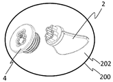
도 4는 도 1c 에서 단지 예시적인 방식으로 나와 있는 발명에 따른 다부품 온수병용 안전 클로저가 있는 온수병을 보여준다.
도 5a-5j는 발명에 따른 수동 작동 요소에서 돌출되는 또는 클로저 부품에서 돌출되는 힘 전달 요소의 선호되는 교차 단면에 대한 상이한 도식적 도해를 보여준다.
도 6는 비인가 방식으로 제3자에 의해 사용될 수 없는 발명에 따라 닫힌 온수병을 보여준다.
도 7a는 선호되는 클로저 부품의 투시 도해를 보여준다.
도 7b는
도 7a 에 나와 있는 클로저 부품과 일치하는 수동 작동 요소의 투시 도해를 보여준다.
도 8a-c는 발명에 따른 클로저 부품들에 대한 도식적 단면 도해를 보여준다.
도 8d-f는 발명에 따른 수동 작동 요소들을 통한 도식적 단면 도해를 보여준다.
도 9a는 발명에 따른 클로저 부품의 예시에 대한 평면도를 보여준다.
도 9b는 도 9a에서 알려진 클로저 부품의 투시 저면도를 보여준다.
도 9c는 도 9b에서 투시 묘사된 클로저 부품의 저면도를 보여준다.
도 10a는 도 9a 에서 B-B로 식별된 단면에 따른 하나의 단면 도해를 보여준다.
도 10b는 도 9a에서 A-A로 식별된 단면에 따른 단면 도해를 보여준다.
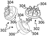
도 11a-b는 클로저 부품 부착 요소의 제1차 실시예에 대한 두 가지 도식적 및 단지 예시적인 도해를 보여준다.
도 11c-d는 이에 따라 도 11a-b의 클로저 부품 부착 요소가 온수병 클로저 부품에 연결되는 두 가지 도식적 및 단지 예시적인 도해를 보여준다.
도 11e-f는 클로저 부품 부착 요소의 제2차 실시예의 두 가지 도식적 및 단지 예시적인 도해를 보여준다.
도 11g는 이에 따라 도 11e-f 의 클로저 부품 부착 요소가 온수병 클로저 부품에 연결되는 도식적 및 단지 예시적인 도해를 보여준다.
도 11h는 클로저 부품 부착 요소의 추가로 가능한 실시예에 대한 세 가지 도식적 및 단지 예시적인 도해들을 보여준다.
도 11i-k는 클로저 부품 부착 요소를 연결하기 위한 중앙 커플링 위치가 있는 온수병 클로저의 두 가지 도식적 및 단지 예시적인 도해를 보여준다.
도 11l-m는 선호하게는 도 11i-k에 나와 있는 온수병 클로저 부품의 커플링 위치에 부정적으로, 선호하게는 적어도 커플링 핀의 영역 안에 구현되는 추가적인 클로저 부품 부착 요소의 두 가지 도식적 및 단지 예시적인 도해를 보여준다.
도 12a는 각각 어댑터 또는 중간 구성원으로서 구현되는 클로저 부품 부착 요소에 대한 평면도의 도식적 및 단지 예시적인 도해를 보여준다.
도 12b는 도 12a에 나와 있는 클로저 부품 부착 요소의 측면도에 대한 도식적 및 단지 예시적인 도해를 보여준다.
도 12c는 도 12a 에 나와 있는 클로저 부품 부착 요소의 저면도에 대한 도식적 및 단지 예시적인 도해를 보여준다.
도 12d는 도 12a-c 에 나와 있는 클로저 부품 부착 요소의 묘사에 대한 도식적 및 단지 예시적인 투시 도해를 보여준다.
도 12e는 온수병 클로저 부품의 단면 도해를 보여준다.
도 12f는 도 12d에서 보여지는 클로저 부품 부착 요소 및 도 12e 에서 보여지는 온수병 클로저 부품의 예시적인 단면 도해를 결합된 배치로 보여준다.
도 13a-d는 서로 다른 로트를 보여준다, 여기에서 각각의 로트는 하나의 포장과 적어도 세균이 감소된 방식으로 포장 안에 각각 보관 또는 배치되는 발명에 따른 하나의 물체를 포함한다.Figure 1a shows a diagrammatic side view of a first exemplary embodiment of a manually actuated element according to the invention.
Figure 1B shows a schematic plan view of a first exemplary embodiment of a closure part according to the invention.
Figure 1c shows a schematic side view of a first exemplary multi-part hot water bottle safety closure according to the invention.
Figure 1d shows a top view of a safety closure for a multi-part hot water bottle according to the first embodiment of the invention.
Figure 2a shows schematically a side view of a second exemplary embodiment of a manually operated element according to the invention and a schematic side view of a secondary closure part according to the invention in an unconnected state.
Figure 2b shows a schematic top view of a second exemplary embodiment of a multi-part hot water bottle safety closure according to the invention.
Figure 2c shows a schematic bottom view of a second exemplary passive operating element according to the invention.
Figure 2d shows a schematic top view of a second exemplary closure part according to the invention.
Figure 3a shows a third exemplary embodiment of a passive actuating element according to the invention and a schematic side view of a secondary closure part according to the invention in a combined arrangement.
Figure 3b shows a third exemplary embodiment of a manually operated element according to the invention and a schematic side view of a second closure part according to the invention in an unconnected arrangement.
Figure 3c shows a further schematic side view of a third exemplary passive operating element according to the invention in which the passive actuating element is depicted rotated by 90 ° compared to the example shown in Figure 3b.
Figure 3d shows a schematic plan view of the third passive actuating element depicted in an illustrative manner wherein the passive actuating element is oriented according to Figure 3b.
Figure 4 shows a hot water bottle with safety closures for multi-part hot water bottles according to the invention, shown in an exemplary manner only in Figure 1c.
Figures 5a-5j show different schematic illustrations of the preferred cross-section of the force-transmitting element projecting from the closure part or protruding from the passive actuating element according to the invention.
Figure 6 shows a closed hot water bottle according to the invention which can not be used by a third party in an unattended manner.
Figure 7a shows a perspective view of a preferred closure part.
Figure 7b shows a perspective view of a manual operating element in accordance with the closure part shown in Figure 7a.
Figures 8a-c show a schematic cross-sectional view of closure components according to the invention.
Figures 8d-f show diagrammatic cross-sectional views through passive operating elements according to the invention.
Figure 9a shows a top view of an example of a closure part according to the invention.
Figure 9b shows a perspective bottom view of a known closure part in Figure 9a.
Figure 9c shows a bottom view of the closure part pictured in Figure 9b.
Figure 10a shows one cross-sectional view along the section identified by BB in Figure 9a.
Figure 10B shows a cross-sectional view along the section identified by AA in Figure 9A.
Figures 11a-b show two schematic and only exemplary illustrations of a first embodiment of a closure component attachment element.
Figures 11c-d show two schematic and only exemplary illustrations in which the closure component attachment elements of Figures 11a-b are thus connected to a hot water bottle closure part.
Figures 11e-f show two schematic and only exemplary illustrations of a second embodiment of the closure component attachment element.
Fig. 11g shows a schematic and exemplary illustration in which the closure component attachment elements of Figs. 11e-f are connected to a hot water bottle closure component.
Figure 11h shows three schematic and exemplary illustrations of a further possible embodiment of the closure component attachment element.
Figures 11i-k show two schematic and exemplary illustrations of a hot water bottle closure with a central coupling position for connecting the closure component attachment elements.
Figures 11I-m are preferably two schematic illustrations of additional closure component attachment elements that are implemented negatively, preferably at least in the region of the coupling pin, in the coupling position of the hot water bottle closure component shown in Figures < RTI ID = An illustrative illustration is shown.
Figure 12a shows a schematic and exemplary illustration of a top view of a closure component attachment element implemented as an adapter or intermediate member, respectively.
Figure 12b shows a schematic and only exemplary illustration of a side view of the closure component attachment element shown in Figure 12a.
Figure 12c shows a schematic and only exemplary illustration of a bottom view of the closure component attachment element shown in Figure 12a.
Figure 12d shows a schematic and only exemplary perspective view of the depiction of the closure part attachment elements shown in Figures 12a-c.
12E shows a cross-sectional view of a hot water bottle closure part.
Figure 12f shows an exemplary cross-sectional view of the closure component attachment element shown in Figure 12d and the hot water bottle closure component shown in Figure 12e in a combined configuration.
Figs. 13a-d show different lots, wherein each lot comprises one package and at least one object according to the invention in which the bacteria are stored or placed, respectively, in the package in a reduced manner.
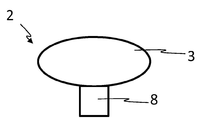
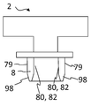
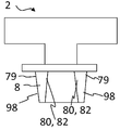
도 1a은 수동 작동 요소 2를 보여준다. 수동 접촉 및 힘 인가 3을 위한 요소의 모양은 여기에서 타원형으로 묘사되지만 또한 둥글거나, 직사각형이거나 다른 모든 모양일 수 있다. 참조 번호 8은 제2차 커플링 요소를 식별하는데, 이는 묘사된 실시예에서 핀형 방식으로 구현된다. 핀형 제2차 커플링 요소 8의 교차 단면 모양에 대한 예시는 도 5a에서 5f까지에서 보여진다. 도 5a에서 5e까지 나와 있는 교차 단면들은 상응하게 또는 부정적으로 구현된 각각의 클로저 부품 4(도 1b 및 1c 참조)의 제1차 커플링 요소 6과의 긍정적인 연결을 위해 제공한다. 도 5f에서 보여지는 교차 단면은 각각 제2차 커플링 요소 8의 마찰 연결 또는 클램핑을 요구하는데, 이는 핀형 방식으로 구현되며, 클로저 부품 4의 제1차 커플링 요소 6의 수단에 의해, 이는 각각 부정적으로 구현되거나 상응하도록 구현된다. 참조 번호 10은 선호하게는 각각 특별히 선호하게는 밀봉 수단으로서 기능하거나 또는 밀봉 수단을 가지고 있거나 및/또는 멈추개로서 기능하는 외주 칼라를 식별한다.Figure 1 a shows a
도 2a에서 2d는 클로저 부품 4 위에 배치되거나 구현된 제1차 커플링 요소 6이 이에 따라 핀형 방식으로 구현된 예시적인 실시예를 보여준다. 수동 접촉 3 및 각각 힘 적용 또는 인가를 위한 요소 위에 형성되거나 마련되는 제2차 커플링 요소 6은 이에 의해 제1차 커플링 요소 6에 대해 각각 부정적으로 또는 상응하도록 형성된다.2a to 2d show an exemplary embodiment in which the
도 3a-3d는 도식적으로 하나의 실시예를 보여 주는데, 이에 따라 제1차 커플링 요소 6과 제2차 커플링 요소 8이 각각 평평 또는 상당히 평평하게 구현된다. 이에 따라 제1차 커플링 요소 6과 제2차 커플링 요소 8은 각 경우에 자석에 의해 형성되는 것이 가능하다. 대안으로는 또는 추가적으로, 제1차 커플링 요소 6와 제2차 커플링 요소 8이 걸이와 고리 체결 장치를 형성하는 것도 가능하다.Figs. 3a-3d schematically show one embodiment, whereby the
도 4는 발명, 특히 도 1c에 나와 있는 다부품 온수병용 안전 클로저에 따른 온수병 1에 대한 다부품 안전 클로저의 예와 함께 발명에 따른 온수병 14를 보여준다.Fig. 4 shows a
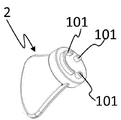
도 5i는 수동 작동 요소 2를 보여주는데, 이는 도 5j로부터 클로저 부품 4에 상응하도록 구현된다. 마찬가지로, 도 5g는 수동 작동 요소 2를 보여주는데, 이는 도 5h에 나와 있는 클로저 부품 4에 상응하도록 구현된다. 두 가지 경우 모두, 제1차 힘 전달 요소 6과 제2차 힘 전달 요소 8은 제1차 힘 전달 요소 6의 부분적 힘 전달 요소 100이 제2차 힘 전달 요소 8의 부분적 힘 전달 요소 101에 대해 특히 부정적으로 상응하도록 구현되는 적어도 부분적으로, 그리고 선호하게는 완전히 서로 간에 간격이 떨어진 부품인 부분적 힘 전달 요소 100, 101의 각각 복수, 특히 적어도 2, 적어도 3, 적어도 4, 적어도 5, 적어도 6, 적어도 7, 적어도 10 또는 적어도 15이다. 부분적 힘 전달 요소 100은 선호하게는 클로저 부품 4의 부품으로서 생성되고 부분적 힘 전달 요소 101은 특히 사출 성형 과정에서 수동 작동 요소 2의 부품으로서 생성된다. Fig. 5i shows a
도 6는 온수병 14를 보여주는데, 이는 본 발명에 따라 닫히며, 여기에 묘사되지 않은 수동 작동 요소 2가 제3자 또는 제3자들에게 접근 가능하게 되지 않는 한 비인가 방식으로 제3자에 의해 열릴 수 없다. 클로저 부품 4는 각각 클로저 부품 4를 돌리거나 열기 위해 요구되는 힘이 클로저 부품 4로 인가될 수 없거나 인원에 의해 인가될 수 없기 때문에 오로지 힘만 사용하는 사람이 온수병을 열 수 없는 방식으로 설계되어 있다.Figure 6 shows a
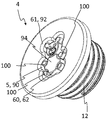
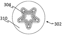
도 7a는 발명에 따른 클로저 부품의 투시도를 보여준다. 제1차 힘 전달 요소 6은 적어도 단면적으로, 특히 대부분 또는 완전히 곡면이 되도록 구현된다는 것이 보여질 수 있다.Figure 7a shows a perspective view of a closure part according to the invention. It can be seen that the primary
제2차 힘 전달 요소 8가 인가될 수 있는 적어도 클로저 부품의 관통 영역의 적어도 하나의 부품은 선호하게는 적어도 단면적으로, 그리고 선호하게는 대부분, 그리고 특별히 선호하게는 완전히 관통 영역 90을 둘러싸는 벽면 92에 의해 경계가 지워진다.At least one part of the through area of the closure part to which the secondary
본 발명의 선호되는 실시예에 따르면, 제1차 힘 전달 요소 8은 하나의 벽면, 특히 하나의 둘러싸는 벽면 92에 의해 형성되는데, 여기에서 벽면 92는 관통 영역 92, 특히 움푹 들어간 부분 5의 경계를 짓는데, 여기에서 관통 영역 92, 특히 움푹 들어간 부분 5는 선호하게는 줄무늬 모양의, 특히 외주 외곽선을 설명하며, 여기에서 움푹 들어간 부분 5는 선호하게는 10mm 미만, 특히 9mm 미만 또는 8mm 미만 또는 7mm 미만 또는 6mm 미만 또는 5mm 미만 또는 4mm 미만 또는 3mm 미만, 특히 예를 들어 1mm와 2mm 사이와 같은 0.5mm와 2.9mm 사이로 해당 외곽선에 대해 직각으로 확장한다. 제1차 힘 전달 요소 8은 선호하게는 외부 힘 전달 표면 61 및/또는 내부 힘 전달 표면 62를 통해 클로저 부품 4의 제2차 힘 전달 요소 6과 협동할 수 있는 방법으로 구현된다.According to a preferred embodiment of the invention, the primary
움푹 들어간 부분 5는 선호하게는 너무 좁거나 너무 크게 설계되고 선호하게는 클로저 부품 4를 작동하기 위한 의도가 아닌 칼이나 동전 등과 같은 장치들이 클로저를 여는데 사용될 수 없는 방식으로 굽은 모양으로 설계된다. The recessed portion 5 is preferably designed to be too narrow or too large and is preferably designed in such a manner that devices such as knives or coins, etc., which are not intended to actuate the
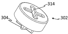
도 7b는 발명에 따른 수동 작동 요소 4의 투시도를 보여준다. 제2차 힘 전달 요소 8이 적어도 단면적으로, 특히 대부분 또는 완전히 곡면이 되도록 구현된 것을 볼 수 있다.Figure 7b shows a perspective view of a manually
적어도 제2차 힘 전달 요소 8의 단면들은 외부 벽면 79를 가지고 있는데, 이는 관통 영역 90의 둘러싸는 벽면 92에 연결될 수 있다. At least the cross sections of the secondary
본 발명의 선호되는 실시예에 따르면, 제2차 힘 전달 요소는 벽면에 의해 형성되는데, 여기에서 벽면은 10mm 미만의 두께, 특히 9mm 미만 또는 8mm 미만 또는 7mm 미만 또는 6mm 미만 또는 5mm 미만 또는 4mm 미만 또는 3mm 미만, 특히 1mm와 2mm 사이 등과 같이 0.5mm와 2.9mm 사이의 두께를 가지고 있다. 제2차 힘 전달 요소 8은 선호하게는 외벽의 외부 힘 전달 표면 81 및/또는 내부 벽면 80의 내부 힘 전달 표면 82를 통하여 클로저 부품 4의 제1차 힘 전달 요소 6과 협동할 수 있는 방식으로 설계된다.According to a preferred embodiment of the present invention, the secondary force transmitting element is formed by a wall surface, wherein the wall surface has a thickness of less than 10 mm, in particular less than 9 mm or less than 8 mm or less than 7 mm or less than 6 mm or less than 5 mm or less than 4 mm Or less than 3 mm, in particular between 1 mm and 2 mm, and the like between 0.5 mm and 2.9 mm. The secondary
적어도 제2차 힘 전달 요소 8의 외부 힘 전달 표면 81은 선호하게는 제1차 힘 전달 요소 6의 외부 힘 전달 표면 61과 협동하고 및/또는 적어도 제2차 힘 전달 요소 8의 내부 힘 전달 표면 82는 제1차 힘 전달 요소 6의 내부 힘 전달 표면 62와 협동한다. 여기에서 클로저 부품 4가 수동 작동 요소 2에 따라 외부 힘 전달 표면 62, 61만 가지는 것이 가능하다는 것은 당연하다.At least the outer force transmitting surface 81 of the secondary
여기에서 둘러싸는 방식으로 관통 영역 90의 경계를 짓는 벽면 92의 외부 힘 전달 표면은 선호하게는 클로저 부품 또는 수동 작동 요소의 회전 축에서 융기부의 외부 힘 전달 표면보다 더 이격되어 있는데, 여기에서 각각의 구성 요소는 온수병의 열기와 닫기에 대응하여 회전축 주위를 회전한다. 외부 힘 전달 표면 61, 62는 클로저 부품 2가 온수병에 채워질 때 접근될 수 있는 클로저 부품 2의 측면(외부)에 위치하고, 내부 힘 전달 표면 160, 161은 클로저 부품 2가 온수병, 예를 들어 나사산이 있는 피스 15 내에 끼워질 때 접근될 수 없는 클로저 부품 2의 측면(내부)에 위치한다. Wherein the external force transmitting surface of the
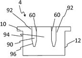
도 8a-8c는 발명에 따른 클로저 부품 4에 대한 예시들의 세 가지 서로 다른 도해를 보여준다. 하지만 개별적 클로저 부품 4의 관통 영역 90은 다르다. 도 8a와 8b는 융기부 94를 가지고 있는 클로저 부품을 보여주는 반면, 도 8c는 그러한 융기부가 없고, 따라서 융기부 94의 외부 외주벽 60을 가지고 있지 않다. 도 8a 및 8b에 따르면, 관통 영역은 부분적으로, 단면적으로, 완전히 또는 완전히 뾰족해 지도록 구현될 수 있다. 하지만, 관통 영역이 벽면 92, 60에 의해 경계가 지워질 수도 있는데, 이것들은 선호하게는 서로 평행 방향이거나 경사 방향일 수 있다. 참조 번호 96은 관통 영역 90의 뾰족해 지는 부분을 식별한다.Figures 8a-8c show three different illustrations of examples of
도 8d-8f의 수단에 의해 예시적인 방식으로 묘사된 예시적인 수동 작동 요소 2는 각각의 경우에 손잡이 부품 3을 가지고 있다. 도 8e와 8f에 의해 묘사된 예들은 더 나아가 힘 전달 표면 82를 형성하기 위한 내부 벽면 80을 가지고 있다. 제2차 힘 전달 수단 8(수동 작동 요소 2의)이 내부 벽면 80을 통해 클로저 부품 4를 제1차 힘 전달 요소 6(클로저 부품 4의)에 끼우고 빼기 위해서만 각각 힘 또는 기세를 인가하는 것이 가능하다. 대안으로는, 하지만, 힘이 내부 표면 80, 82 및 외벽 79를 통해 전달되는 것이 가능하다. 더 나아가 힘과 기세가 외부 표면을 통해서만 전달되는 것이 가능하다. 도 8d은 힘과 기세를 전달하기 위한 내부 표면을 가지고 있지 않고 따라서 외부 표면 79를 통해서만 힘과 기세를 전달하는 예를 들어 수동 작동 요소 2를 보여준다.Exemplary
각각의 나와 있는 수동 작동 요소 2가 도 8c에 따른 클로저 부품과 협동할 수 있는 것이 가능하다. 더 나아가 도 8e와 8f에 따른 수동 작동 요소들이 도 8a와 8b 에 따른 클로저 부품 4와 협동할 수 있는 것이 가능하다.It is possible for each of the
클로저 부품 4와 수동 작동 요소 2는 그리하여 선호하게는 제1차 힘 전달 요소 6과 제2차 힘 전달 요소 8의 협동의 수단에 의해 특히 마찰적으로 또는 긍정적인 연결 또는 자기 연결에 의해 결합된 상태이다. 점 압력 또는 선 압력 또는 표면 압력이 선호하게는 제1차 힘 전달 요소 6과 제2차 힘 전달 요소 8 사이에 형성될 수 있으며, 이 수단에 의해 마찰 연결이 선호하게는 생성된다. 클로저 부품 4는 클로저 부품 4를 풀 때 수동 작동 요소 2의 수단에 의해 긴장이 실리고, 그리하여 완전히 풀리는 순간에 수동 작동 요소 2에 의해 직접적으로 유지되기 때문에 이것은 장점이 된다. 사용자가 그렇게 하여 물체를 자신의 손에 쥐고 더욱 쉽게 채울 수 있기 때문에 이것은 극히 유용하다. 나사를 푸는 순간에, 클로저 부품 4는 더 나아가 아래로 떨어지지 않고, 이에 의해 손실의 위험이 있을 수 있다.The
본 발명의 더 선호되는 실시예에 따르면, 융기부 94의 벽면 60의 융기부 표면 62(또는 융기부 벽면 60)와 둘러싸는 벽면 92의 외부 힘 전달 표면 61 사이의 거리가 12mm 미만, 특히 11mm 미만 또는 9 미만 또는 8mm 미만 또는 7mm 미만 또는 6mm 미만 또는 5mm 미만 또는 4mm 미만 또는 3mm 미만 또는 2mm 미만, 특히 1.5mm 미만 또는 1mm이다. 융기부 94와 둘러싸는 벽면 92는 선호하게는 동일한 높이 또는 상당히 동일한 높이를 가지고 있다. According to a more preferred embodiment of the present invention, the distance between the ridge portion surface 62 (or ridge wall surface 60) of the
제2차 힘 전달 요소 8는 선호하게는 융기부 94의 벽면 60 및/또는 둘러싸는 벽면 92의 외부 힘 전달 표면 61을 통해 제1차 커플링 요소 6에 연결될 수 있다.The secondary
클로저 부품 의 회전 중심 방향으로 안내되는 벽면 92의 표면은 이에 의해 선호하게는 외부 힘 전달 표면 61로서 파악되고, 외부(특히 방사형으로 외부)로 안내되는 융기부 94의 벽면 60의 표면과 적어도 이의 외부 힘 전달 표면 61에 의해 둘러 쌓이는 부위는 이에 의해 선호하게는 외부 힘 전달 표면 62로서 파악된다.The surface of the
융기부 94는 선호하게는 방수 밀폐와 온수병 열기를 위해 클로저 부품 2에 대해 2Nm +/- 0.1Nm의 토크의 인가가 50N 초과, 특히 60N 초과 또는 70N 초과의 힘을 통해 융기부 94에 대한 힘의 적용을 요구하는 방식으로 설계되는데, 여기에서 선호되는 실시예, 특히 이 실시예에 따른 융기부 94는 돌출되지 않거나 칼라 10을 세로 방향 L로 경계를 짓는 칼라 표면 13 위로 클로저 부품 2의 세로 방향 L로 특히 최대 7mm 또는 최대 6mm 또는 최대 5mm 또는 최대 4mm 또는 최대 3mm 또는 최대 2mm 또는 최대 1mm로 약간 돌출한다. 이에 더해 또는 대안으로는, 적어도 제2차 힘 전달 요소 8의 단면들이 관통 영역 90의 둘러싸는 벽면 92에, 이에 의해, 또한 둘러싸는 벽면 92에 연결될 수 있는 외벽 79를 가지고 있는데, 관통 영역 90은 선호하게는 또한 둘러싸는 벽면 92에 의해 경계가 지워지는 적어도 하나의 영역에 의해 구성되는 적어도 하나의 융기부 94, 특히 핀 모양 또는 기둥 모양 요소에 의한 적어도 하나의 벽면 60의 수단에 의해서도 경계가 지워진다.The
도 9a는 발명에 따른 클로저 부품 2의 예에 대한 평면도를 보여준다. 클로저 부품 4는 수동 작동 요소 2를 수취하기 위한 관통 영역 90을 가지고 있다. 이 특수한 실시예에 따르면, 관통 영역 90은 한편으로는 관통 영역을 둘러싸는 벽면 92의 수단에 의해 경계가 정해진다. 반면에, 관통 영역 90은 융기부 94에 의해 형성되는 벽면 60에 의해 경계가 지워진다. 대안으로는, 하지만, 이에 의해 벽면 60 과 그리하여 융기부 90이 형성되지 않는 것이 또한 가능하다. 참조 번호 10은 클로저 부품 4의 칼라를 식별한다.Figure 9a shows a top view of an example of a
도 9b는 도 9a에서 알려진 클로저 부품 4의 투시 저면도를 보여준다. 해당 도해로부터 복수의, 특히 두 개보다 많은 공동 공간 30-35, 선호하게는 3개보다 많은, 및 특별히 선호하게는 4개보다 많은, 예를 들어 5 또는 6개 등이 벽면 92와 나사산을 가지고 있는 외주벽 28 사이에 구현된다. 측면 아래에 있는 클로저 부품 위에는, 관통 영역 90을 둘러싸는 적어도 벽면 92의 단면들이 그렇게 나사산이 있는 외주벽 28로부터 이격되어 있어서, 서로 경계가 지워진 복수의 빈 공간 30-34가 나사산이 있는 외주벽 28과 관통 영역 90을 둘러싸는 벽면 92 사이에 구현되거나 외주 빈 공간이 둘러싸는 벽면 92와 나사산이 있는 외주벽 28 사이에 구현된다. 공동 공간 30-34 또는 공동 공간 35는 선호하게는 둘러싸는 외주벽 28의 최대 벽면 두께로부터 귀결되는데, 여기에서 최대 벽면 두께는 5mm 미만이며, 특히 4mm 미만이거나 3mm 미만이거나 2mm 미만이다. 이에 더하여 또는 대안으로는, 칼라 10은 적어도 1mm 또는 1.5mm 또는 2mm의 두께를 가지고 있고 선호하게는 세로 방향 L 로 적어도 2.5mm 또는 적어도 2.8mm 또는 적어도 3.0mm 또는 적어도 3.3mm 또는 적어도 3.45mm 또는 적어도 3.55mm 또는 적어도 3.6mm 또는 적어도 3.65mm 또는 적어도 3.7mm 또는 적어도 3.75mm를 가지고 있는 칼라 벽면에 의해 형성된다.Figure 9b shows a perspective bottom view of the known
도 9b와 도 9c는 더 나아가 밀봉 13 또는 밀봉 요소 13를 각각 보여준다. 밀봉 또는 밀봉 요소는 각각 선호하게는 칼라 10의 부품이며, 특히 단편으로 형성되어 있다. 온수병을 밀봉하기 위해, 밀봉 13 또는 밀봉 요소 13은 각각 선호하게는 누름에 의해 나사산이 있는 피스 15와 협동하거나 또는 밀봉 목적으로 누름에 의해 온수병 몸체를 형성하는 재료의 부분과 협동한다. 적어도 나사산이 있는 피스 15의 단면들은 선호하게는 온수병 몸체를 형성하는 재료들에 의해 둘러 쌓이고, 적어도 나사산이 있는 피스 15의 단면들을 재료에 의해 선호하게는 특히 삽입 성형된다. 밀봉 목적으로, 밀봉 13 또는 밀봉 요소 13은 각각 특별히 선호하게는 나사산이 있는 피스를 둘러싸는 온수병 몸체의 재료와 협동한다.Figures 9b and 9c further illustrate the
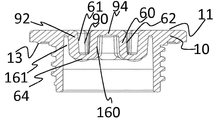
도 10a는 도 9a에 나와 있는 클로저 부품 4의 단면도를 보여준다. 이 실시예에서 관통 영역 90은 외부의 관통 영역을 둘러싸는 벽면 92에 의해 경계가 정해질 수 있음을 알 수 있다. 이 실시예와 선호하게는 관통 영역 90을 가지고 있는 모든 다른 실시예들에서, 이 벽은 두께가 적어도 0.8mm이고 선호하게는 적어도 1mm 두께이고, 특별히 선호하게는 적어도 1.2mm 두께 또는 적어도 1.5mm 두께 또는 적어도 1.8mm 두께 또는 적어도 2mm 두께이다. 벽면 92는 선호하게는 최대 5mm 두께이고 특별히 선호하게는 최대 3mm 두께 또는 최대 2.5mm 두께 또는 최대 2mm 두께 또는 최대 1.5mm 두께이다. 교차 단면 도해에서, 벽면 92의 외부 표면 61은 선호하게는 표면 11에 대해 경사지게 구현되며, 특히 60°와 90° 사이의 각으로 형성되며 선호하게는 70°와 89° 사이 또는 80°와 88° 사이의 각으로 형성된다.Figure 10a shows a cross-sectional view of the
융기부 94를 형성하는 벽면 60은 선호하게는 적어도 0.8mm 두께이고 선호하게는 적어도 1mm 두께이고 특별히 선호하게는 적어도 1.2mm 두께이고 또는 적어도 1.5mm 두께이고 또는 적어도 1.8mm 두께 또는 적어도 2mm 두께이다. 벽면 60은 선호하게는 최대 5mm 두께이고 특별히 선호하게는 최대 3mm 두께 또는 최대 2.5mm 두께 또는 최대 2mm 두께 또는 최대 1.5mm 두께이다. 교차 단면 도해에서, 벽면 60의 외부 표면 62는 선호하게는 표면 11에 대하여 경사지게, 특히 60°와 90° 사이의 각으로 형성되고, 선호하게는 70°와 89° 사이 또는 80°와 88° 사이의 각으로 형성되도록 구현된다.The
벽면 92는 선호하게는 곧바로 벽면 60에 연결되거나 또는 연결 벽면 64 또는 연결 벽면 부분 64를 통해 각각 연결될 수 있다. 연결 벽면 64는 선호하게는 적어도 0.8mm 두께이며 선호하게는 적어도 1mm 두께이고 특별히 선호하게는 적어도 1.2mm 두께 또는 적어도 1.5mm 두께 또는 적어도 1.8mm 두께 또는 적어도 2mm 두께이다. 연결 벽면 64는 선호하게는 최대 5mm 두께이고 특별히 선호하게는 최대 3mm 두께 또는 최대 2.5mm 두께 또는 최대 2mm 두께 또는 최대 1.5mm 두께이다.The wall surfaces 92 are preferably connected directly to the
벽면 92는 더 나아가 하나의 내부 표면 161이 있다. 교차 단면적 도해에서, 벽면 92의 내부 표면 161은 선호하게는 표면 11에 대해 경사지게 구현되고, 그것이 특히 60°와 90° 사이의 각으로 형성되고 선호하게는 70°와 89°도 사이의 각 또는 80°와 88° 사이의 각으로 형성된다.The
벽면 60은 더 나아가 각각 하나의 내부 또는 내부 표면 160을 가지고 있다. 교차 단면 도해에서, 벽면 60의 내부 표면 160은 표면 11과 관련하여 경사지도록 구현되고, 특히 60°와 90° 사이의 각으로 형성되고, 선호하게는 70°와 89° 또는 80°와 88° 사이의 각도로 구현된다.The
참조 번호 151은 나사산이 있는 단면의 내부 벽면을 나타낸다.
도 10b는 치수에 대한 선호되는 예를 규정한다. 높이 H는 이에 의해 선호하게는 941로 식별되는 벽면 부분의 두께를 파악한다. 벽면 부분 941은 선호하게는 선호하게는 적어도 0.8mm 및 선호하게는 적어도 1mm 및 특별히 선호하게는 적어도 1.2mm 또는 적어도 1.5mm 또는 적어도 1.8mm 또는 적어도 2mm의 높이 H1이다. 벽면 부분 941은 선호하게는 최대 5mm 및 특별히 선호하게는 최대 3mm 또는 최대 2.5mm 또는 최대 2mm 또는 최대 1.5mm의 높이 H1을 가지고 있다.Figure 10b defines a preferred example for dimensions. The height H thereby preferably grasps the thickness of the wall portion identified by 941. The wall portion 941 is preferably a height H1 of at least 0.8 mm, and preferably at least 1 mm, and particularly preferably at least 1.2 mm, or at least 1.5 mm, or at least 1.8 mm, or at least 2 mm. The wall portion 941 preferably has a height H1 of at most 5 mm and particularly preferably at most 3 mm or at most 2.5 mm or at most 2 mm or at most 1.5 mm.
이에 따른 높이 H2는 선호하게는 관통 영역 90의 높이를 나타낸다. 관통 영역 90은 선호하게는 적어도 0.8mm와 선호하게는 적어도 1mm와 특별히 선호하게는 적어도 1.2mm 또는 적어도 1.5mm 또는 적어도 1.8mm 또는 적어도 2mm 또는 적어도 3mm 또는 적어도 4mm 또는 적어도 5mm의 높이 H2를 가지고 있다. 관통 영역 90은 선호하게는 최대로 15mm와 특별히 선호하게는 최대 12mm 또는 최대 10mm 또는 최대 8mm 또는 최대 5mm 또는 최대 2mm의 높이 H2를 가지고 있다. The
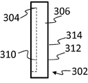
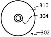
도 11a는 클로저 부품 부착 요소 302 또는 온수병용 안전 클로저의 클로저 부품 부착 요소 302에 대한 도식적 투시 도해를 각각 보여준다. 클로저 부품 부착 요소 302는 이에 의해 적어도 하나의 기능적 수단 306을 가지고 있는데, 여기에서 기능적 수단 306은 하나의 기능적 영역 308(도 11b, 11m 또는 12b 참조)을 형성하는데, 여기에서 기능적 영역 308은 온수병용 안전 클로저를 위한 클로저 부품 4의 힘 전달 요소 6의 적어도 부분적 겹침에 의해 형성된다. 선호하게는, 하나 또는 정확히 하나 또는 적어도 하나의 위치 조정 수단 304이 각각 기능적 수단 306 위에 또는 안에(특히 자석 부분으로서) 또는 부품으로서 배치되거나 형성된다. 하지만, 복수의 위치 조정 수단 304가 기능적 수단 306 위에 각각 배치되거나 형성되는 것이 이에 의해 또한 가능하다. 위치 지정 요소 304는 선호하게는 제1차 측면 310 위에 또는 기능적 수단 306의 제1차 측면 위에 각각 배열되거나 형성되거나, 또는 위치 지정 요소들이 제1차 측면 310의 위에 또는 기능적 수단 306의 제1차 측면 위에 각각 배열되거나 형성된다. 제1차 측면 310의 반대편에 위치한 측면에서는, 기능적 수단 306이 선호하게는 제2차 측면 312에 의해 경계가 지어진다. 제2차 측면 312는 그에 의하여 선호하게는 단면에 있어 또는 완전히 평평한 하나의 표면을 형성한다. 대안으로는, 하지만, 제2차 측면 312에 의해 형성된 표면이 적어도 단면적으로 3차원인 구조(예를 들어, 도 11d 또는 12a 참조)를 구현하는 것도 가능하다. 제2차 측면 312는 그에 의하여 선호하게는 하나의 커플링 표면 314(도 11a) 또는 커플링 구조 314(도 12a)를 형성한다.11A shows a schematic perspective view of the closure
더 나아가 기능적 수단 306은 자기적으로 형성되거나 또는 적어도 또는 정확히 하나의 자석 요소 또는 자석 부분을 가지고 있는 것이 가능하다. 역시 자기적으로 활성 상태인 요소는 그런 다음 선호하게는 제2차 측면 312를 통해 클로저 부품 부착 요소 302에 자기적으로 결합된다. 이에 더해 또는 대안적으로, 제2차 측면 312가 추가적인 요소가 물질 연결 또는 긍정 또는 마찰 방식으로 그 위에서 해제되도록 또는 해제되지 않도록 배치될 수 있는 방식으로 형성되는 것이 가능하다.Furthermore, it is possible for the functional means 306 to be magnetically formed or to have at least or exactly one magnet element or magnet portion. The magnetically active element is then magnetically coupled to the closure
도 11b는 도 11a의 도해의 측면도를 나타낸다.Fig. 11B shows a side view of the Fig. 11A view.
도 11c는 발명에 따른 클로저 부품 부착 요소 302의 추가적인 예와 함께, 본 발명에 따른 클로저 부품 4 또는 온수병용 안전 클로저를 위한 클로저 부품 4의 각각의 조립체에 대한 측면도를 보여준다. 이 도해로부터, 클로저 부품 부착 요소 302가 온수병용 안전 클로저를 위한 클로저 부품 4에 연결되어 있는 상태에서, 기능적 수단 306은 선호하게는 제2차 측면 312(도 11b 참조)에서 선호하게는 보이거나 만질 수 있거나 접근 가능하며, 이는 제1차 측면 310과 다르고 이는 선호하게는 상당하 곳에 위치하거나 정확히 제1차 측면 310과 평행이다. 클로저 부품 부착 요소 302이 온수병용 안전 클로저의 클로저 부품 4에 연결되는 상태에서, 기능적 수단 306의 제1차 측면 310은 선호하게는 적어도 부분적으로 눈에 보이지 않거나 만질 수 없거나 접근할 수 없거나 가려져 있다.11C shows a side view of each assembly of the
도 11d는 도 11c에서 제시된 조립체의 한 단면적인 도해를 보여준다. 단면은 그에 의해 도 11c에서 "A"에 의해 파악된 절단선에 따라 흐른다. 이 도해로부터 기능적 수단 306이 전자적 수단 316을 가지고 있음을 알 수 있다. 선호하게는 하나, 정확히 하나 또는 적어도 하나의 전자적 수단 316이 제공되는 것은 본 발명의 정신에 속하고, 이에 의해 특히 기능 영역 308에 완전히 또는 부분적으로 내장될 수 있도록 두 개, 정확히 두 개 또는 두 개 이상의 전자적 수단 316이 제공되는 것이 가능하다. 전자적 수단 316이 인접하기 위해 제1차 측면 또는 표면 310 위로 및/또는 기능적 수단 306의 각각의 제2차 측면 또는 표면 312 위로 돌출되는 것이 가능하다. 더 나아가 전자적 수단 316 또는 복수의 전자적 수단 316이 제1차 측면 310과 제2차 측면 312 사이에 각각 배타적으로 또는 완전하게 형성되는 것이 더욱 가능하다. 전자적 수단 316은 선호하게는 특히 각각 온도 센서 및/또는 밝기 센서 또는 조명 센서 및/또는 습도 센서 및/또는 동작 센서, 및/또는 적산기 및/또는 프로세서 장치 및/또는 통신 장치, 특히 Bluetooth, 및/또는 디스플레이 및/또는 음향 출력 장치 및/또는 방사선원, 특히 조명원, 특히 LED 조명 및/또는 전기적 에너지 생산 장치, 특히 태양열 장치 및/또는 압전 요소 장치, 특히 하나 또는 복수의 압전 요소들을 가지고 있는 센서 수단이다. 선호하게는, 전자적 수단 316은 위에서 언급된 복수의 구성 요소 및/또는 장치를 가지고 있는 장치이다.FIG. 11D shows a diagram, which is a cross-sectional view of the assembly shown in FIG. 11C. The cross section is thereby caused to flow along the cut line identified by "A " in Fig. 11C. From this illustration it can be seen that the functional means 306 have
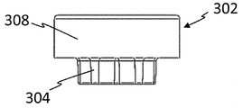
도 11e는 선호하게는 열 절연 클로저 덮개로서 구현되는 덮개인 클로저 부품 부착 요소 302를 보여준다. 클로저 부품 부착 요소 302는 이에 의해 선호하게는 마찰적으로 발명에 따른 클로저 부품 4의 칼라 10에 선호하게는 적어도 단면적으로 그리고 특별히 선호하게는 완전히 외주 위치 지정 요소 304로서 구현되는 고정 영역 308의 수단에 의해 연결될 수 있다.11E shows a closure
도 11g는 도 11e와 11f에 나온 클로저 부품 부착 요소 302가 발명에 따라 클로저 부품 4 위에 배치되는 상태를 보여준다. Fig. 11g shows a state in which the closure
도 11h은 각각의 경우에 클로저 부품 4의 상응하게 구현된 힘 전달 요소 6와 협동할 수 있거나 각각 연결될 수 있는 추가적인 클로저 부품 부착 요소 302의 예를 보여준다. 그러한 의존적인 디자인은 힘이 각각 위치 지정 요소 304 또는 위치 지정 요소 304의 협동의 수단에 의해 각각 클로저 부품 4의 힘 전달 요소 6 또는 힘 전달 요소들 6으로 인가될 수 있기 때문에 장점이 있다. 도 11e에서 11g 에서 적어도 도식적으로 묘사된 클로저 부품 4의 칼라 10을 통한 커플링 대안은 클로저 부품 4의 힘 전달 요소 6의 각각의 디자인으로부터 독립적이기 때문에 더욱 장점이 된다. Fig. 11H shows an example of an additional closure
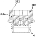
도 11i은 온수병용 안전 클로저를 위한 클로저 부품 4의 더 선호되는 예에 대한 하나의 단면적 도해를 보여준다. 이 예에 따르면, 클로저 부품 4은 중앙에서 상부에 있는 칼라 10의 경계를 짓는 표면 11의 측면으로부터 나사산 12에 의해 둘러싸인 영역으로 확장하는 하나의 중앙 커플링 위치 318을 가지고 있다. 커플링 위치 318은 그에 의하여 선호하게는 클로저 부품 4를 특히 축 방향으로 위쪽으로 밀봉하는 벽면 319의 부분이다. 커플링 위치 318의 표면 321은 선호하게는 적어도 단면적으로 원뿔형 또는 핀 모양의 디자인을 형성한다. Figure 11i shows a cross-sectional view of one more preferred example of the
도 11k는 도 11i에 나와 있는 클로저 부품 4에 대한 평면도를 보여준다.11K shows a top view of the
도 11l은 발명에 따른 클로저 부품 부착 요소 302의 추가적인 예에 대한 도식적 저면도를 보여준다. 참조 번호 308은 이에 의해 기능적 수단 306의 제1차 측면 또는 클로저 부품 부착 요소 302의 기능적 수단 306의 아래쪽을 각각 식별한다. 더 나아가 선호하게는 클로저 부품 4의 커플링 위치 318에 상응하도록 구현되는 위치 조정 수단 304가 선호하게는 기능적 수단 306의 아래쪽 310의 중앙에 각각 구현되거나 배치되는 것이 보여질 수 있다. Figure l l shows a schematic bottom view of a further example of a closure
도 11m은 도 1ll에 나와 있는 클로저 부품 부착 요소 302의 측면도를 보여준다.FIG. 11M shows a side view of the closure
그것은 더 나아가 기능적 수단 306의 모양이 하나의 둥근, 특히 디스크 모양과 다른 모든 클로저 부품 부착 요소에 대해 적용된다.Which further applies to all of the closures component attachment elements in which the shape of the
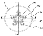
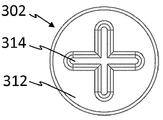
도 12a는 제2차 측면 32, 특히 더 선호되는 클로저 부품 부착 요소 302의 기능적 수단 306의 외부 표면에 대한 평면도의 도식적 도해를 보여준다. 기능적 수단 306의 제2차 측면 312는 이에 의해 선호하게는 3차원적으로 설계된 커플링 표면 314을 형성한다. 커플링 표면 314는 선호하게는 추가적인 요소에 대한 커플링을 위해, 특히 각각 온수병용 안전 클로저를 위한 수동 작동 요소 또는 수동 작동 요소 2에 대한 커플링을 위해 기능한다. 커플링 표면 314는 그에 의해 선호하게는 하나의 십자가 모양을 형성한다. 하지만, 커플링 표면 314가 십자가 모양과 다른 모양을 형성하는 것이 이를 통해 가능하다. Figure 12A shows a schematic view of a plan view of the
도 12b는 클로저 부품 부착 요소 302의 측면도를 나타낸다. 도 12a와의 조합을 통해, 도 12a 에서 보이는 십자가 모양 커플링 표면 314가 기능적 수단 306 또는 기능적 영역 308에서 각각 침하로서 구현되는 것이 보여질 수 있다. 대안으로는, 하지만, 커플링 표면 314 또는 3차원 커플링 구조 314가 각각 돌출되도록 구현될 수 있는 것도 가능하다. 선호하게는 적어도 하나의 위치 조정 수단 304가 기능적 영역 308 또는 기능적 수단 306에 각각 인접한다. 위치 조정 수단 304는 선호하게는 클로저 부품 4의 힘 전달 요소 6에 대해 부정적으로 구현된다. 본 도해에 따르면, 위치 조정 수단 304는 별 모양 방식으로 구현되는데, 여기에서 대안으로는 서로 다른 모양, 특히 원과 고리와 다른 서로 다른 모양들이 될 수 있다.12B shows a side view of the closure
도 12c는 도 12a와 12b에 나와 있는 클로저 부품 부착 요소 302의 아래쪽 310에 대한 평면도를 보여준다.12C shows a top view of the
도 12d는 도 12a-c에서 이미 묘사된 클로저 부품 부착 요소 302를 투시도로 보여준다.Figure 12d shows a perspective view of the closure
단지 예시적인 방식으로, 도 12e는 도 10a에도 나와 있는 클로저 부품 4의 도해를 보여준다.In an exemplary manner only, FIG. 12E shows an illustration of the
도 12f는 도 12d에 나와 있는 클로저 부품 부착 요소 302와 도 12e에 나와 있는 클로저 부품 4 의 조립체에 대한 하나의 단면 도해를 보여준다. Figure 12f shows a cross-sectional view of the closure
각각 도면 12a-12d에 따라 또는 유사하게 설계된 클로저 부품 부착 요소 302는 선호하게는 중간 구성원 또는 어댑터로 식별될 수도 있다.Closure
특별히 선호하게는, 적어도 클로저 부품 부착 요소 302의 부품들은 사출 성형 부품 또는 3D 인쇄 구성 요소들이다. 클로저 부품 부착 요소 302는 선호하게는 적어도 부분적으로는 하나의 고분자 재료, 특히 PE, PA, PLA 또는 이들의 조합으로 구성된다. Particularly preferably, at least the parts of the closing
도 13a-d는 본 발명에 따른 서로 다른 적어도 세균이 감소된, 특히 멸균된 포장된 물체를 보여준다. 이를 통해 이들 도면들에서 나온 모든 가능한 조합의 물체들이 세균이 줄어든, 특히 살균 방식의 포장에 마련될 수 있는 것도 가능하다. 선호하게는, 이들 도면에 나온 포장 200은 부피 또는 양의 면에 있어서 적어도 부분적 또는 대부분 또는 완전히 고분자 재료로, 특히 폴리프로필렌 또는 폴리아미드 또는 폴리에틸렌 또는 적어도 이들 두 가지 재료의 조합이거나 그것들을 각각 가지고 있는 포장이다.Figures 13a-d show different, at least germ-less, specially sterilized packaged objects according to the present invention. It is thus possible that all possible combinations of objects emerging from these drawings can be provided in a germ-less packaging, in particular in a sanitizing manner. Preferably, the
참조 번호 202는 포장 200에 의해 경계가 정해진 세균이 감소된, 특히 멸균된 영역을 식별한다.
도 13a에서, 나와있는 물체들은 온수병 1을 위한 다부품 안전 클로저를 가지고 있는 온수병 14, 도 13b 클로저 부품 부착 요소, 도 13c 온수병을 위한 안전 클로저를 위한 클로저 부품 4와 온수병용 안전 클로저를 수동 작동 요소 2 및 도 13d 추가적인 클로저 부품 부착 요소 302, 특히 하나의 어댑터이다.In Fig. 13a, the objects shown are a
제공은 더 나아가 선호하게는 특히 직물 재료를 가지고 있는 온수병 덮개를 위한 이 포장 200 중 하나로 이루어질 수 있다.The provision may furthermore preferably consist of one of these
포장 200은 물체의 인입과 후속적인 밀봉, 특별히 선호하게는 포장의 파괴의 결과로서만, 예를 들어, 각각 상응하는 물체를 제거하기 위해 세균 감소의 제거 또는 멸균 상태의 제거에 의해서만 열릴 수 있다.The
1
다부품 온수병용 안전 클로저
2
온수병용 안전 클로저를 위한 수동 작동 요소 또는 수동 작동 요소
3
수동 접촉용 요소
4
안전 클로저 온수병용 클로저 부품 또는 클로저 부품
5
움푹 들어간 부분
6
제1차 힘 전달 요소
8
제2차 힘 전달 요소
10
칼라
11
세로 방향 l로 칼라의 경계를 정하는 표면
12
외부 나사산
13
외주 밀봉 요소
14
온수병
15
나사산이 있는 피스
16
깔때기
17
나사산이 있는 피스의 내부 나사산
28
외부 나사산이 있는 외주벽
30
제1차 공동 공간 또는 제1차 침하, 각각
31
제2차 공동 공간 또는 제2차 침하, 각각
32
제3차 공동 공간 또는 제3차 침하, 각각
33
제4차 공동 공간 또는 제4차 침하, 각각
34
제5차 공동 공간 또는 제5차 침하, 각각
35
중앙 공동 공간 또는 중앙 침하, 각각
60
융기부의 벽면
61
제1차 힘 전달 요소 또는 둘러싸는 벽면 92의 각각의 외부 힘 전달 표면
62
융기부 벽면의 외부 힘 전달 표면
64
연결 벽면
79
제2차 힘 전달 요소의 외부 벽면 부분
80
제2차 힘 전달 요소의 내부 벽면 부분
81
제2차 힘 전달 요소의 외부 힘 전달 표면
82
제2차 힘 전달 요소의 내부 힘 전달 표면
90
제1차 힘 전달 요소의 관통 영역
92
제1차 힘 전달 요소의 둘러싸는 벽면 또는 제1차 힘 전달 요소의 둘러싸는 벽면
94
제1차 힘 전달 요소의 융기
96
뾰족해지는 부분
98
증가하는 부분
100
클로저 부품의 부분적 힘 전달 요소
101
수동 작동 요소의 부분적 힘 전달 요소
151
나사산이 있는 단면의 내부 벽면
160
벽면 부분 60의 내부 표면
161
벽면 부분 92의 내부 표면
200
포장
202
수취 영역
300
클로저 부품 아래쪽
302
클로저 부품 부착 요소 또는 온수병용 안전 클로저의 클로저 부품 부착 요소
304
위치 지정 요소
306
기능적 수단
308
기능적 영역
310
기능적 수단의 제1차 측면
312
기능적 수단의 제2차 측면
314
커플링 표면
316
전자적 수단
318
중앙 커플링 위치
941
융기부의 중앙 벽면 부분
A
거리
L
세로 방향
H1
높이 1
H2
높이 21 Multi-component hot water safety closures
2 Manual or manual operating elements for safety closures for hot water bottles
3 Components for manual contact
4 Safety closures Hot water bottle closure parts or closure parts
5 indented part
6 Primary force transfer element
8 Second force transfer element
10 colors
11 Surface that bounds the color in the portrait direction l
12 External thread
13 Outer Sealing Element
14 hot water bottles
15 Threaded piece
16 funnel
17 Internal thread of threaded piece
28 Outer wall with external thread
30 The first common space or primary settlement, respectively
31 Second common space or secondary settlement, respectively
32 third common space or third settlement, respectively
33 Fourth common space or fourth settlement, respectively
34 Fifth Common Space or Fifth Settlement, respectively
35 central cavity or central sink, respectively
60 Wall of ridge
61 primary force transmitting element or enclosing
62 External force-transmitting surface of the ridge wall
64 Connection wall
79 outer wall portion of the secondary force transmitting element
80 inner wall portion of the secondary force transmitting element
81 External force transmitting surface of secondary force transmitting element
82 inner force transmitting surface of the secondary force transmitting element
90 penetration area of the primary force transmitting element
92 The enclosing wall of the primary force transmitting element or the surrounding wall surface of the primary force transmitting element
94 Bump of primary force transfer element
96 Sharpened parts
98 Increasing parts
100 Partial force-transmitting element of the closure part
101 Partial force-transmitting element of a manual operating element
151 Internal wall of threaded section
The inner surface of the
The inner surface of
200 Packing
202 Receiving area
300 Closure part lower
302 Closures Closures for component elements or safety closures for hot water bottles Component attachment elements
304 Positioning elements
306 functional means
308 Functional area
310 First side of functional means
312 Secondary aspects of functional means
314 Coupling Surface
316 Electronic means
318 Center coupling position
941 Central wall portion of ridge
A distance
L portrait orientation
Claims (16)
온수병의 내부 나사산으로 채우기 위한 외부 나사산(12)을 가지고 있고,
온수병(14)을 방수 방식으로 밀봉하기 위해 클로저 부품(4)을 온수병의 내부 나사산(14)에 끼우고 온수병(14)의 내부 나사산(17)으로부터 클로저 부품(4)을 풀기 위한 힘을 전달하기 위한 제1차 힘 전달 요소(6)를 가지고 있는
클로저 부품(4)와
온수병(14)의 내부 나사산(17)으로 채우거나 클로저 부품(4)로 풀기 위해 요구되는 힘을 인가하기 위한 제2차 힘 전달 요소(8)을 가지고 있는
수동 작동 요소(2)로 구성되며
제1차 힘 전달 요소(6)와 제2차 힘 전달 요소(8)가 클로저 부품(4)과 수동 작동 요소(2)가 작동 연결을 형성함으로써 서로 해제될 수 있게 연결될 수 있는 방식으로 대응하도록 구현됨을 특징으로 하는
다부품 온수병용 안전 클로저(1)At least
Has an external thread (12) for filling with internal threads of the hot water bottle,
To seal the hot water bottle 14 in a waterproof manner, the closure part 4 is inserted into the internal thread 14 of the hot water bottle and the force for unscrewing the closure part 4 from the internal thread 17 of the hot water bottle 14 (6) for delivering a first force
Closure parts (4) and
Has a secondary force transmission element (8) for applying a force required to fill with internal threads (17) of the hot water bottle (14) or unwind with the closure part (4)
Consists of a manual operating element (2)
So that the primary force transmitting element 6 and the secondary force transmitting element 8 correspond in such a way that the closure component 4 and the passive actuating element 2 can be releasably connected to each other by forming an operational connection Characterized in that
Multi-component hot water safety closures (1)
제1차 힘 전달 요소(6)가 특히 걸이 및 고리형 체결장치를 가지고 있는 평평한 힘 전달 요소로 구현되고, 제2차 힘 전달 요소(8)도 또한 역시 걸이 및 고리형 체결장치를 가지고 있는 평평한 힘 전달 요소로서 구현되는 것을 특징으로 하는
청구항 1에 따른 다부품 온수병용 안전 클로저A primary force transmitting element 6 is embodied as an inner force transmitting element and is embodied by the surrounding wall portions, wherein the secondary force transmitting element 8 is embodied in at least a cross- Or
The primary force transmitting element 6 is embodied in a flat force transmitting element, in particular having a hook and an annular fastening device, and the secondary force transmitting element 8 also has a flat, Characterized in that it is implemented as a force transfer element
A safety closures for multi-component hot water bottles according to claim 1
청구항 2에 따른 다부품 온수병용 안전 클로저At least a portion of the penetrating region 90 of the closure component 4 to which the secondary force transmitting element 8 can be applied is delimited by means of a wall surface surrounding the penetrating region 90 at least in cross- Characterized by
A safety closures for multi-component hot water bottles according to claim 2
융기부(94)의 벽면(60)과 둘러싸는 벽면(92) 사이의 거리(A)는 12mm 미만이며,
여기에서 융기부(94)와 둘러싸는 벽면(92)은 선호하게는 동일한 높이 또는 상당히 동일한 높이를 가지고 있고,
및/또는
융기부(94)는 방수 밀폐 및 온수병을 열기 위해 클로저 부품(2)에 2Nm +/- 0.1Nm의 토크의 인가가 50N를 초과하는 힘으로 융기부에 대한 힘의 적용을 요구하는 방식으로 설계되는데, 여기에서 융기부(94)는 돌출되지 않거나 또는 칼라(10)를 세로 방향 L로 경계를 짓는 칼라 표면(13) 위로 클로저 부품(2)의 세로 방향(L)으로 살짝만 돌출하며,
및/또는
적어도 제2차 힘 전달 요소(8)의 단면들은 관통 영역(90)의 둘러싸는 벽면(92)으로 연결될 수 있는 외벽(79)을 가지고 있는데, 관통 영역(90)도 또한 적어도 하나의 융기부(94)에 의한 적어도 하나의 벽면(60)의 수단에 의해 경계가 지어지고, 이는 둘러싸는 벽면(92), 특히 핀형 또는 기둥형 요소에 의해 경계가 지어지는 영역에 구현되는 것을 특징으로 하는
청구항 3에 따른 다부품 온수병용 안전 클로저The ridges 94 are embodied on the closure component 4 wherein the ridges 94 are surrounded by a wall surface 92 that encloses at least a cross-
The distance A between the wall surface 60 of the ridge 94 and the surrounding wall surface 92 is less than 12 mm,
Wherein the ridge 94 and surrounding wall surface 92 preferably have the same height or substantially the same height,
And / or
The ridges 94 are designed in such a way that the application of a torque of 2 Nm +/- 0.1 Nm to the closure component 2 to open the watertight seals and hot water bottles requires the application of force to the ridges in a force exceeding 50 N Wherein the ridge 94 does not protrude or slightly protrudes in the longitudinal direction L of the closure part 2 over the collar surface 13 which bounds the collar 10 in the longitudinal direction L,
And / or
At least the cross-sections of the secondary force transmitting element 8 have an outer wall 79 that can be connected by a surrounding wall surface 92 of the penetrating region 90. The penetrating region 90 also has at least one raised portion 94 by means of at least one wall surface 60 which is embodied in an area bounded by the surrounding wall surface 92, in particular by a pin or columnar element
A safety closures for multi-component hot water bottles according to claim 3
청구항 3 또는 4 중 하나에 따른 다부품 온수병용 안전 클로저At the bottom 300 of the closure part there are at least a plurality of spaced apart walled surfaces 92 surrounding the perforated area 90 from the threaded outer wall 28, 30-34 are implemented between the surrounding wall surface 92 and the threaded outer wall 28 or between the surrounding wall surface 92 and the threaded outer wall 28 by an outer peripheral void space Characterized by
A safety closures for multi-component hot water bottles according to one of claims 3 or 4
청구항 1에 따른 다부품 온수병용 안전 클로저The primary force transmission element 6 is arranged in the longitudinal direction of the closure component 2 above the collar surface 13 which bounds the protruding force transmission element 6, in particular the collar 10, in the longitudinal direction L of the closure component. Wherein the protruding force transfer element 6 of the closure part 2 is provided with a torque of 2 Nm +/- 0.1 Nm to the closure part 2 for watertight seals and hot water bottle openings, Characterized in that the application is designed in such a way as to require the application of a force to the projecting force transmitting element (6) with a force of more than 50 N, in particular more than 70 N
A safety closures for multi-component hot water bottles according to claim 1
클로저 부품(4)는 적어도 단면적으로 그리고 선호하게는 완전하게 외주 칼라(10)를 가지고 있는데, 여기에서 칼라(10)는 최대 나사 인입 깊이를 제헌하기 위한 멈추개 및/또는 해당 외주 밀봉 요소(13)가 선호하게는 곡면형의 접촉 표면을 가지고 있는 융기부로서 구현되는 외주 밀봉 요소(13)로서 구현되고, 칼라(10)의 단편(one-piece) 조각이며 클로저 부품(2)에 대해서도 그러하고, 및/또는
클로저 부품(4) 및/또는 수동 작동 요소(2)는 고분자 재료가 적어도 100°C의 온도 안정성을 가지고 있는 고분자 재료로 구성된 사출 성형된 부품이고 및/또는
클로저 부품(4)은 적어도 12mm, 특히 적어도 16mm의 개구부 지름을 가지고 있는 온수병 개구부를 막기 위해 구현되고,
작동 연결을 수립하기 위해, 제1차 힘 전달 요소(6)와 제2차 힘 전달 요소(8)는 제1차 힘 전달 요소(6)와 제2차 힘 전달 요소(8)의 상응하는 부분들이 서로 접촉하게 되는 방식으로 서로 접촉하게 될 수 있는데, 여기에서 상응하는 부분들은 적어도 단면적으로, 특히 대부분 또는 완전히 곡면형이 되도록 구현되는 점을 특징으로 하는
이전 청구항들 중 하나에 따른 다부품 온수병용 안전 클로저The coupling between the manual operating element 2 and the closure part 4 is at least released when the closure part 4 for closing the hot water bottle 14 is fitted in the internal thread 17 of the hot water bottle 14, And / or
The closure part 4 has at least a cross-sectional area and preferably completely a circumferential collar 10, wherein the collar 10 has a stop and / or a corresponding outer circumferential sealing element 13 Is implemented as a circumferential sealing element 13 embodied as a ridge having a curved contact surface, preferably a one-piece piece of collar 10 and so on for the closure part 2, And / or
The closure component 4 and / or the manual actuating element 2 is an injection molded part composed of a polymeric material in which the polymeric material has a temperature stability of at least 100 [deg.] C and / or
The closure component 4 is embodied to prevent hot water bottle openings having an opening diameter of at least 12 mm, in particular at least 16 mm,
The primary force transmitting element 6 and the secondary force transmitting element 8 are connected to each other by a corresponding part of the primary force transmitting element 6 and the secondary force transmitting element 8, May be brought into contact with each other in such a way that they are brought into contact with each other, wherein the corresponding parts are realized to be at least in cross section, in particular most or completely curved
Safety closures for multi-component hot water bottles according to one of the preceding claims
이전 청구항 중 하나에 따른 다부품 온수병용 안전 클로저The closure component 4 and the passive actuating element 2 are arranged such that the primary force transmitting element 6 and the secondary force transmitting element 8 are connected to the primary force transmitting element 6 and the secondary force transmitting element 8 cooperate in a clamping manner, in particular in such a way that they are kept in a coupled state
Safety closures for multi-component hot water bottles according to one of the previous claims
청구항 1의 서문에 따른 다부품 온수병용 안전 클로저There is provided at least one closure part attachment element 302 for a releasable arrangement between the passive actuating element 2 and the closure part 4 wherein the closure part attachment element 302 is provided with a first force Is adapted to correspond to the transmission element 6 and on the other hand to correspond to the secondary force transfer element 8 wherein the force applied through the passive element 2 is transmitted to the secondary force transfer element 8, To the closure component attachment element (302) through the first closure component (4) and through the latter to the closure component (4)
The safety closures for multi-component hot water bottles according to the preamble of claim 1
클로저 부품(4)를 온수병(14)의 내부 나사산(17)에 끼우거나 빼고 클로저 부품(4)에 끼우거나 빼기 위해 요구되는 힘을 인가하기 위한 힘 전달 요소(8)로 구성되는데, 여기에서 힘 전달 요소(8)은 작동 연결을 형성함으로써 클로저 부품(4)에 연결될 수 있는
선행 청구항들 중 하나에 따른 다부품 온수병용 안전 클로저에서 사용하기 위한 온수병용 안전 클로저를 위한 수동 작동 요소(2)At least
Consists of a force transfer element 8 for applying the required force to insert or withdraw the closure part 4 into or out of the internal thread 17 of the hot water bottle 14 and to insert or withdraw it into the closure part 4, The force-transmitting element 8 can be connected to the closure part 4 by forming a working connection
(2) for a hot water bottle safety closures for use in a multi-part hot water bottle safety closures according to one of the preceding claims,
및
온수병(14)을 방수 밀폐를 위해 온수병(14)의 내부 나사산(17)에 채우고 온수병(14)의 내부 나사산(17)에서 클로저 부품(4)을 풀기 위한 힘을 전달하기 위한 힘 전달 요소(6)로 구성되는
청구항 1에서 9에 따른 다부품 온수병용 안전 클로저에서 사용하기 위한 온수병용 안전 클로저를 위한 클로저 부품(4).
여기에서 힘 전달 요소는 작동 연결을 형성함으로써 온수병용 안전 클로저를 위한 수동 작동 요소(2)에 연결될 수 있고, 여기에서 힘 전달 요소(6)는 적어도 단면적으로, 특히 대부분 또는 완전히 곡면이 되도록 구현된다.An external thread 12 for filling the internal threads 17 of the hot water bottle 14,
And
A force for transferring the force to unseal the closure component 4 from the internal thread 17 of the hot water bottle 14 and to fill the internal thread 17 of the hot water bottle 14 for watertight sealing, Element < RTI ID = 0.0 > (6)
Closure component (4) for a safety closures for hot water bottles for use in safety closures for multi-component hot water bottles according to claims 1 to 9.
Here, the force transmitting element can be connected to the passive operating element 2 for the safety closures for hot water bottles by forming working connections, wherein the force transmitting elements 6 are embodied to be at least in cross section, in particular most or fully curved .
적어도
온수병용 안전 클로저의 클로저 부품(4) 위에 배치하기 위한 하나의 위치 지정 요소(304) 또는 복수의 위치 지정 요소
및
적어도 하나의 기능적 수단(306), 여기에서 기능적 수단(306)은 선호하게는 하나의 기능적 영역(308)을 형성하며, 여기에서 기능적 영역(308)은 선호하게는 적어도 단면적으로 온수병용 안전 클로저의 클로저 부품(4)의 힘 전달 요소(6)를 적어도 단면적으로 겹치도록 구현된다,
여기에서 위치 지정 요소(304)는 제1차 측면(310) 위에 또는 기능적 수단(306)의 제1차 측면 위에 마련되거나 또는 위치 지정 요소들이 제1차 측면(310) 위에 또는 기능적 수단(306)의 제1차 측면 위에 마련된다.Closure component attachment element (302) for a safety closures for a hot water bottle for a releasable connection with a closure component (4) of a safety closure for a hot water bottle according to claim 11,
At least
One positioning element 304 or a plurality of positioning elements 304 for placement on the closure part 4 of the safety closures for hot water bottles
And
Wherein at least one functional means 306, wherein the functional means 306 preferably form one functional region 308, wherein the functional region 308 is preferably at least a cross- Sectional area of the force transmitting element (6) of the closure part (4)
The positioning element 304 may be provided on the primary side 310 or on the primary side of the functional means 306 or the positioning elements may be provided on the primary side 310, On the first side.
청구항 10에 따른 안전 클로저 온수병을 위한 수동 작동 요소(2)과 청구항 11에 따른 안전 클로저 온수병을 위한 클로저 부품(4)와 선호하게는 청구항 12에 따른 안전 클로저 온수병을 위한 클로저 부품 부착 요소(302)
및
하나의 충전용 개구부와 하나의 나사산(17)이 온수병용 안전 클로저(11)에 대한 결합을 위한 충전 개구부의 영역에 마련되어 있는 적어도 하나의 온수병(14)과
온수병(14) 주변에 마련될 수 있는 선호하게는 온수병 덮개로
구성되는
키트At least
(2) for a safety closure hot water bottle according to claim 10 and a closure part (4) for a safety closure hot water bottle according to claim 11 and preferably a closure part attachment element (302)
And
At least one hot water bottle (14) provided with one filling opening and one thread (17) in the region of the filling opening for engagement with the safety closures (11) for hot water bottles
Preferably, a hot water bottle cover may be provided around the hot water bottle (14)
Constituted
Kit
특히 적어도 부분적으로 수취 영역(202)의 경계를 짓는 고분자 재료로 구성된 포장 (200)
및
청구항 10에 따른 수취 영역(202)에 포장(200)에 의해 적어도 액체 밀폐 방식으로 둘러쌓이는 온수병용 안전 클로저를 위한 수동 작동 요소(2) 및/또는
청구항 11에 따른 온수병용 안전 클로저를 위한 클로저 부품(4) 및/또는
청구항 12에 따른 온수병용 안전 클로저를 위한 클로저 부품 부착 요소(302)
또는
수취 영역(202) 내에 포장(200)에 의해 적어도 액체 밀폐 방식으로 둘러 쌓인 청구항 13에 따른 키트로 구성되는
로트.
단, 여기에서 포장(200)에 의해 경계가 지워진 전체 수취 영역(202)은 세균이 감소된, 특히 멸균 상태이다.At least
In particular, a package 200 comprising a polymeric material that at least partially delimits the receiving area 202,
And
(2) for a safety closures for hot water bottles surrounded at least in a liquid-tight manner by a package (200) in a receiving area (202) according to claim 10 and / or
Closure component (4) for a safety closures for hot water bottles according to claim 11 and / or
Closure component attachment element (302) for a safety closures for hot water bottles according to claim 12,
or
The kit according to claim 13, which is enclosed in the receiving area (202) by the package (200) at least in a liquid-tight manner
Lot.
Here, however, the entire receiving area 202 bounded by the package 200 is a sterilized state in which bacteria are reduced.
온수병용 안전 클로저를 위한 클로저 부품(4) 및/또는 온수병용 안전 클로저를 위한 수동 작동 요소(2) 또는 다부품 온수병용 안전 클로저(1) 또는 클로저 부품 부착 요소(302)에 양식 데이터를 제공하는 단계,
3D 프린터를 제어하고 온수병용 안전 클로저를 위한 클로저 부품(4) 및/또는 온수병용 안전 클로저 또는 다부품 온수병용 안전 클로저(1)를 위한 수동 작동 요소(2) 또는 온수병용 안전 클로저를 위한 클로저 부품 부착 요소(302)를 인쇄하기 위해 양식 데이터를 제어 장치로 업로드하는 단계.(2) for a safety closures for hot water bottles according to claim 10 and / or a closure part (4) for safety closures for hot water bottles according to claim 11, or at least one of claims 1 to 9 A safety closure for a multi-part hot water bottle or a production method for producing a closure part attachment element according to claim 12
(2) for a closure part (4) for a hot water bottle safety closure and / or a safety closure (1) or a closure part attachment element (302) for a multi part hot water bottle step,
(2) for closure components for controlling 3D printers and for safety closures for hot water bottles (4) and / or safety closures (1) for safety closures or multi-component hot water bottles for bottles or closures Uploading form data to the control device to print attachment element 302.
특히 청구항 15에 따른 방법을 수행하기 위한 컴퓨터 프로그램 제품
A digital description of the form of the manual operating element (2) for a safety closures for hot water bottles according to claim 10 and / or of a closure part (4) for hot water bottle safety closures according to claim 11 or of claims 1 to 9 Wherein the digital description comprises a digital description of a multi-part hot water bottle safety closure (1) and / or a closing component attachment element (302) for a hot water bottle safety closure according to claim 12, Can be used to control
A computer program product for performing the method according to claim 15,
Applications Claiming Priority (11)
| Application Number | Priority Date | Filing Date | Title |
|---|---|---|---|
| DE102014119307 | 2014-12-20 | ||
| DE102014119307.5 | 2014-12-20 | ||
| DE102015101853.5 | 2015-02-10 | ||
| DE102015101853 | 2015-02-10 | ||
| DE102015114180.9 | 2015-08-26 | ||
| DE102015114180 | 2015-08-26 | ||
| DE102015114671 | 2015-09-02 | ||
| DE102015114671.1 | 2015-09-02 | ||
| DE102015117217.8 | 2015-10-08 | ||
| DE102015117217 | 2015-10-08 | ||
| PCT/EP2015/080681 WO2016097386A2 (en) | 2014-12-20 | 2015-12-18 | Safety closure for a hot-water bottle |
Publications (1)
| Publication Number | Publication Date |
|---|---|
| KR20170108940A true KR20170108940A (en) | 2017-09-27 |
Family
ID=55085629
Family Applications (1)
| Application Number | Title | Priority Date | Filing Date |
|---|---|---|---|
| KR1020177017037A KR20170108940A (en) | 2014-12-20 | 2015-12-18 | Safety closure for a hot-water bottle |
Country Status (8)
| Country | Link |
|---|---|
| US (1) | US10925766B2 (en) |
| EP (1) | EP3232999B1 (en) |
| JP (1) | JP6850731B2 (en) |
| KR (1) | KR20170108940A (en) |
| CN (1) | CN107427384A (en) |
| DE (1) | DE202015009660U1 (en) |
| PL (1) | PL3232999T3 (en) |
| WO (1) | WO2016097386A2 (en) |
Families Citing this family (2)
| Publication number | Priority date | Publication date | Assignee | Title |
|---|---|---|---|---|
| DE102019005145A1 (en) * | 2019-07-18 | 2021-01-21 | Adrian Klinkmüller | Retrofittable bottle cap |
| USD943759S1 (en) * | 2020-09-16 | 2022-02-15 | Xin Zhao | Hot water bottle |
Family Cites Families (73)
| Publication number | Priority date | Publication date | Assignee | Title |
|---|---|---|---|---|
| GB105735A (en) | ||||
| DE187404C (en) | ||||
| DE487404C (en) | 1929-12-10 | Karl Behr | Closure cap for hot water bottles or the like. | |
| DE611569C (en) | 1935-03-30 | Continental Gummi Werke Akt Ge | Closure for hot water bottles, ice packs, etc. like | |
| US3216632A (en) * | 1965-11-09 | Container wall closure combinations and assemblies | ||
| DE552930C (en) | 1932-06-20 | Friedrich Emil Krauss | Safety valve for hot water bottles or other temporarily pressurized containers | |
| DE55259C (en) | Firma BOLZANO, tedesco & CO in Schlan in Böhmen | Arrangement of the tubes of water tube boilers on both sides of the furnace | ||
| DE552591C (en) | 1932-12-16 | Otto Boerner C | Ear clam | |
| US992928A (en) * | 1910-02-26 | 1911-05-23 | Albert H Walcott | Preserve jar and bottle. |
| GB157173A (en) | 1915-08-27 | 1921-12-22 | Schraders Son Inc | Improvements in stoppers for water bottles and the like |
| GB160712A (en) | 1920-08-06 | 1921-03-31 | Joseph James Purdie | Improvements in and relating to stoppers for hot water bottles |
| US1478918A (en) * | 1922-01-11 | 1923-12-25 | Rupp William | Tap device for wooden barrels |
| GB225915A (en) | 1923-09-07 | 1924-12-08 | William Robert Beldam | Improvements in or relating to hot-water bottles |
| GB227345A (en) | 1924-05-22 | 1925-01-15 | Stanley Lambert | Improvements in hot water bottles |
| GB230731A (en) | 1924-09-12 | 1925-03-19 | Mergenthaler Linotype Gmbh | Improvements in typographical composing and distributing machines |
| GB245968A (en) | 1925-03-11 | 1926-01-21 | George Henry Charles Lumsden | Improvements in or relating to closures for water bottles and the like |
| GB246764A (en) | 1925-10-24 | 1926-02-04 | Frederick William Bing Miles | Improvements in hot water bottles |
| US1810795A (en) | 1927-02-17 | 1931-06-16 | Arthur R Soderquist | Locking key for closure plugs |
| US1737605A (en) * | 1927-09-23 | 1929-12-03 | Mauser Rudolf | Bung for iron transport casks |
| GB304903A (en) | 1928-01-11 | 1929-01-31 | Campbell Achnach And Company L | Improvements in or relating to stoppers for hot water bottles and the like |
| DE511569C (en) | 1928-04-12 | 1930-11-21 | Fritz Werner Akt Ges | Hydraulic control of the slide for tool machines, especially for grinding machines |
| GB374495A (en) * | 1931-03-10 | 1932-06-10 | P B Cow & Company Ltd | Improvements in hot water bottles and the like |
| GB385822A (en) | 1932-04-23 | 1933-01-05 | Joseph Thomas Webb | Venting device for hot water bottles and the like |
| FR819762A (en) * | 1936-03-30 | 1937-10-26 | Closure for metal containers | |
| FR811526A (en) * | 1936-10-01 | 1937-04-16 | New closures for rubber hot water bottles | |
| GB496452A (en) | 1937-04-02 | 1938-11-30 | Us Rubber Prod Inc | Improvements in stoppers |
| GB604341A (en) | 1945-12-21 | 1948-07-01 | David Atkin | Improvements in and relating to bottles and particularly hot water bottles |
| US2439907A (en) | 1947-04-29 | 1948-04-20 | Poglein Louis | Grip for steel drums or the like |
| DE1638820U (en) | 1951-12-12 | 1952-05-29 | Paul Leyh | BED BOTTLE CAP. |
| DE1645057U (en) | 1952-06-19 | 1952-10-09 | Adam Engelhardt | HOT WATER BOTTLE CAP. |
| US2718250A (en) * | 1953-03-31 | 1955-09-20 | Bradford William | Closure structure |
| DE1842006U (en) | 1961-08-17 | 1961-11-23 | Gisela Hock | HEATABLE HOT WATER BOTTLE. |
| GB1094364A (en) | 1963-10-15 | 1967-12-13 | Dunlop Rubber Co | Improvements relating to hot water bottles |
| GB1227892A (en) * | 1969-04-16 | 1971-04-07 | ||
| JPS5733856Y2 (en) | 1976-08-07 | 1982-07-26 | ||
| FR2390268A1 (en) | 1977-05-13 | 1978-12-08 | Segalowicz Joseph | IMPROVEMENTS IN THE MOLDING OF HOLLOW BODIES |
| US4580547A (en) | 1984-06-04 | 1986-04-08 | Kapralis Imants P | Flexible heat pack containing super cooled salt solution |
| JPS6171111U (en) | 1984-10-16 | 1986-05-15 | ||
| JP2566445B2 (en) | 1988-06-10 | 1996-12-25 | 義信 山口 | Thermal storage with built-in trigger |
| JPH063569Y2 (en) | 1988-12-03 | 1994-02-02 | ピジョン株式会社 | Hot water bottle |
| CA2027427A1 (en) | 1990-10-12 | 1992-04-13 | William S. Laidlaw | Plug for sealing wood preservative in wood structures |
| US6634417B1 (en) | 1997-04-07 | 2003-10-21 | J. Bruce Kolowich | Thermal receptacle with phase change material |
| DE59911423D1 (en) * | 1998-05-26 | 2005-02-17 | E & H Grob Ag Kunststoffspritz | Set consisting of hot water bottle, bed screw cap and bed opener |
| DE19900197C2 (en) | 1999-01-06 | 2001-05-23 | Georg Oswald Lange | Rubber bottle |
| US6302902B1 (en) | 1999-04-19 | 2001-10-16 | Anuthep Benja-Athon | Double-bladder paraffin bag |
| DE50007377D1 (en) | 2000-04-22 | 2004-09-16 | Ibs Filtran Kunststoff Metall | Locking system for molded plastic parts |
| US20020193856A1 (en) * | 2001-06-19 | 2002-12-19 | Lu Nan Chih | Water bag with new structure for cold / hot hydrotherapy |
| CA2372648A1 (en) * | 2002-02-20 | 2003-08-20 | Iwi Ltd. | Funnel for waterpillow |
| AU2002348575A1 (en) * | 2002-09-23 | 2004-04-08 | Nicholas A. Caruso | Paint can lid with easy access |
| AU2004200830A1 (en) * | 2003-03-06 | 2004-03-25 | Adams, Paul Mr | Screw Cork System |
| US6869441B2 (en) | 2003-03-21 | 2005-03-22 | Kimberly-Clark Worldwide, Inc. | Thermal therapy sleeve |
| US6968968B2 (en) * | 2003-09-15 | 2005-11-29 | Rieke Corporation | Container closure assembly with snap-on overcap |
| WO2007117159A1 (en) | 2006-04-08 | 2007-10-18 | Carl Ernest Alexander | Energy-efficient bed warmers |
| US20080119916A1 (en) | 2006-10-05 | 2008-05-22 | Ramsey Joe Choucair | Cold Compress for Therapeutic Cooling |
| US20080110305A1 (en) | 2006-11-15 | 2008-05-15 | Cheng-Chien Tsai | Hexagonal spanner |
| US9333112B2 (en) | 2007-04-12 | 2016-05-10 | Medivance Incorporated | Sorption-based adhesive contact cooling apparatus and method |
| US20090048650A1 (en) | 2007-08-14 | 2009-02-19 | Mitch Junkins | Configurable ice pack and heating pad |
| CN201179139Y (en) | 2008-01-04 | 2009-01-14 | 耿新生 | Electrical heating hot water bag of rubber or rubber plastic |
| JP3141182U (en) | 2008-02-13 | 2008-04-24 | マルカ株式会社 | Hot water bottle |
| JP4621264B2 (en) | 2008-03-11 | 2011-01-26 | 山一株式会社 | Thermal storage heater |
| BRPI0913060A2 (en) | 2008-05-12 | 2015-10-13 | Embrace | a system and method for regulating temperature |
| JP5518493B2 (en) | 2010-01-06 | 2014-06-11 | ユーザー株式会社 | Insulation kit |
| CN201647287U (en) | 2010-03-19 | 2010-11-24 | 叶元明 | Hot water bottle cock |
| JP3163042U (en) | 2010-04-09 | 2010-09-30 | 秀史 原 | Hot water bottle with inorganic solid |
| DE202010007284U1 (en) | 2010-04-29 | 2011-09-23 | Fashy Gmbh Produktion Und Vertrieb | Hot water bottle made of plastic |
| CN201668583U (en) | 2010-06-02 | 2010-12-15 | 王秀康 | Hot-water bottle |
| DE202011005112U1 (en) | 2011-04-02 | 2012-07-03 | Fashy Gmbh Produktion Und Vertrieb | Hot water bottle made of plastic |
| US8834548B2 (en) | 2011-06-03 | 2014-09-16 | Embrace | Systems and methods to regulate body temperature |
| CN102512279A (en) | 2011-12-21 | 2012-06-27 | 白可 | Leak-proof hot water bag and production methods thereof |
| CN203306402U (en) | 2013-03-16 | 2013-11-27 | 上虞舜美高分子材料有限公司 | Water filling opening of flexible water container |
| CN110123516B (en) | 2014-01-23 | 2021-08-06 | Wfi沃姆费拉盛创新公司(有限责任) | Heating device with latent heat energy storage unit |
| DE102014201887A1 (en) | 2014-02-03 | 2015-08-06 | Mahle International Gmbh | Closure system for a container |
| CN206606402U (en) | 2016-11-21 | 2017-11-03 | 福建省骏旗机械工贸有限公司 | Turn-over mechanism for the buckled shell packing machine of raw material |
-
2015
- 2015-12-18 EP EP15823331.2A patent/EP3232999B1/en active Active
- 2015-12-18 PL PL15823331T patent/PL3232999T3/en unknown
- 2015-12-18 JP JP2017551014A patent/JP6850731B2/en active Active
- 2015-12-18 DE DE202015009660.3U patent/DE202015009660U1/en active Active
- 2015-12-18 US US15/537,923 patent/US10925766B2/en active Active
- 2015-12-18 WO PCT/EP2015/080681 patent/WO2016097386A2/en active Application Filing
- 2015-12-18 CN CN201580069848.2A patent/CN107427384A/en active Pending
- 2015-12-18 KR KR1020177017037A patent/KR20170108940A/en unknown
Also Published As
| Publication number | Publication date |
|---|---|
| JP6850731B2 (en) | 2021-04-07 |
| WO2016097386A9 (en) | 2016-10-27 |
| US10925766B2 (en) | 2021-02-23 |
| PL3232999T3 (en) | 2022-05-23 |
| WO2016097386A2 (en) | 2016-06-23 |
| US20180125704A1 (en) | 2018-05-10 |
| CN107427384A (en) | 2017-12-01 |
| EP3232999A2 (en) | 2017-10-25 |
| WO2016097386A3 (en) | 2016-08-25 |
| JP2018507759A (en) | 2018-03-22 |
| EP3232999B1 (en) | 2022-01-26 |
| DE202015009660U1 (en) | 2018-11-19 |
Similar Documents
| Publication | Publication Date | Title |
|---|---|---|
| KR101479069B1 (en) | A Safety Cap | |
| EP2714538B1 (en) | A non-removable tamper resistant lid | |
| ATE424928T1 (en) | CONTAINER DEVICES WITH MULTIPLE CLOSURES FOR CONTROLLED DISPENSING OR EXPOSURE OF CONTAINERS CONTENTS | |
| TWM473836U (en) | Portable sterilizing device | |
| KR20170108940A (en) | Safety closure for a hot-water bottle | |
| KR20170013223A (en) | A safety closure for containers | |
| WO2006097640A8 (en) | Closing device with integrated rotary closure for feeding bottle and bottle | |
| GB2333512A (en) | Dispensing container | |
| AU2015356698A1 (en) | Short rotation safety lock for containers and bottle for said lock | |
| WO2007138191A3 (en) | Closure device for bottle | |
| KR100928833B1 (en) | The device for heating and sterilization to nursing bottle using baby | |
| CN212546478U (en) | Container with automatic sterilization function | |
| KR20160060286A (en) | Portable apparatus for sterilization and disinfection of feeding bottle | |
| KR200445674Y1 (en) | Safety cap | |
| KR20140141183A (en) | Medicine bottle telling time to take medicine | |
| BRPI0410737A (en) | plastic bottle bottleneck | |
| JP2004149197A (en) | Safety lid for hollow container and liquid container equipped with the lid | |
| WO2018234602A2 (en) | Container for dispensing a dosed product | |
| JP7054494B2 (en) | Container with automatic sterility function | |
| KR20140033648A (en) | A water discharging cock for system of water purifier | |
| KR100674663B1 (en) | Intermediate implement for nursing bottle's cap | |
| KR200384799Y1 (en) | Child resistance cap | |
| CA3184411A1 (en) | Resealable airtight storage jar assembly | |
| TWM650666U (en) | Intellegent bottle cap with uv led and thermos bottle using the same | |
| JP3112667U (en) | PET bottle can with cap holder |