KR102002269B1 - Euv exposure apparatus - Google Patents
Euv exposure apparatus Download PDFInfo
- Publication number
- KR102002269B1 KR102002269B1 KR1020187024647A KR20187024647A KR102002269B1 KR 102002269 B1 KR102002269 B1 KR 102002269B1 KR 1020187024647 A KR1020187024647 A KR 1020187024647A KR 20187024647 A KR20187024647 A KR 20187024647A KR 102002269 B1 KR102002269 B1 KR 102002269B1
- Authority
- KR
- South Korea
- Prior art keywords
- temperature
- mirror
- ref
- projection lens
- reflective
- Prior art date
Links
Images


Classifications
-
- G—PHYSICS
- G03—PHOTOGRAPHY; CINEMATOGRAPHY; ANALOGOUS TECHNIQUES USING WAVES OTHER THAN OPTICAL WAVES; ELECTROGRAPHY; HOLOGRAPHY
- G03F—PHOTOMECHANICAL PRODUCTION OF TEXTURED OR PATTERNED SURFACES, e.g. FOR PRINTING, FOR PROCESSING OF SEMICONDUCTOR DEVICES; MATERIALS THEREFOR; ORIGINALS THEREFOR; APPARATUS SPECIALLY ADAPTED THEREFOR
- G03F7/00—Photomechanical, e.g. photolithographic, production of textured or patterned surfaces, e.g. printing surfaces; Materials therefor, e.g. comprising photoresists; Apparatus specially adapted therefor
- G03F7/70—Microphotolithographic exposure; Apparatus therefor
- G03F7/70058—Mask illumination systems
- G03F7/7015—Details of optical elements
-
- G—PHYSICS
- G02—OPTICS
- G02B—OPTICAL ELEMENTS, SYSTEMS OR APPARATUS
- G02B27/00—Optical systems or apparatus not provided for by any of the groups G02B1/00 - G02B26/00, G02B30/00
- G02B27/0025—Optical systems or apparatus not provided for by any of the groups G02B1/00 - G02B26/00, G02B30/00 for optical correction, e.g. distorsion, aberration
- G02B27/0037—Optical systems or apparatus not provided for by any of the groups G02B1/00 - G02B26/00, G02B30/00 for optical correction, e.g. distorsion, aberration with diffracting elements
- G02B27/0043—Optical systems or apparatus not provided for by any of the groups G02B1/00 - G02B26/00, G02B30/00 for optical correction, e.g. distorsion, aberration with diffracting elements in projection exposure systems, e.g. microlithographic systems
-
- G—PHYSICS
- G02—OPTICS
- G02B—OPTICAL ELEMENTS, SYSTEMS OR APPARATUS
- G02B27/00—Optical systems or apparatus not provided for by any of the groups G02B1/00 - G02B26/00, G02B30/00
- G02B27/18—Optical systems or apparatus not provided for by any of the groups G02B1/00 - G02B26/00, G02B30/00 for optical projection, e.g. combination of mirror and condenser and objective
-
- G—PHYSICS
- G02—OPTICS
- G02B—OPTICAL ELEMENTS, SYSTEMS OR APPARATUS
- G02B5/00—Optical elements other than lenses
-
- G—PHYSICS
- G02—OPTICS
- G02B—OPTICAL ELEMENTS, SYSTEMS OR APPARATUS
- G02B5/00—Optical elements other than lenses
- G02B5/08—Mirrors
- G02B5/0816—Multilayer mirrors, i.e. having two or more reflecting layers
-
- G—PHYSICS
- G02—OPTICS
- G02B—OPTICAL ELEMENTS, SYSTEMS OR APPARATUS
- G02B5/00—Optical elements other than lenses
- G02B5/08—Mirrors
- G02B5/0891—Ultraviolet [UV] mirrors
-
- G—PHYSICS
- G02—OPTICS
- G02B—OPTICAL ELEMENTS, SYSTEMS OR APPARATUS
- G02B7/00—Mountings, adjusting means, or light-tight connections, for optical elements
- G02B7/18—Mountings, adjusting means, or light-tight connections, for optical elements for prisms; for mirrors
- G02B7/181—Mountings, adjusting means, or light-tight connections, for optical elements for prisms; for mirrors with means for compensating for changes in temperature or for controlling the temperature; thermal stabilisation
- G02B7/1815—Mountings, adjusting means, or light-tight connections, for optical elements for prisms; for mirrors with means for compensating for changes in temperature or for controlling the temperature; thermal stabilisation with cooling or heating systems
-
- G—PHYSICS
- G03—PHOTOGRAPHY; CINEMATOGRAPHY; ANALOGOUS TECHNIQUES USING WAVES OTHER THAN OPTICAL WAVES; ELECTROGRAPHY; HOLOGRAPHY
- G03F—PHOTOMECHANICAL PRODUCTION OF TEXTURED OR PATTERNED SURFACES, e.g. FOR PRINTING, FOR PROCESSING OF SEMICONDUCTOR DEVICES; MATERIALS THEREFOR; ORIGINALS THEREFOR; APPARATUS SPECIALLY ADAPTED THEREFOR
- G03F7/00—Photomechanical, e.g. photolithographic, production of textured or patterned surfaces, e.g. printing surfaces; Materials therefor, e.g. comprising photoresists; Apparatus specially adapted therefor
- G03F7/70—Microphotolithographic exposure; Apparatus therefor
- G03F7/70058—Mask illumination systems
- G03F7/702—Reflective illumination, i.e. reflective optical elements other than folding mirrors, e.g. extreme ultraviolet [EUV] illumination systems
-
- G—PHYSICS
- G03—PHOTOGRAPHY; CINEMATOGRAPHY; ANALOGOUS TECHNIQUES USING WAVES OTHER THAN OPTICAL WAVES; ELECTROGRAPHY; HOLOGRAPHY
- G03F—PHOTOMECHANICAL PRODUCTION OF TEXTURED OR PATTERNED SURFACES, e.g. FOR PRINTING, FOR PROCESSING OF SEMICONDUCTOR DEVICES; MATERIALS THEREFOR; ORIGINALS THEREFOR; APPARATUS SPECIALLY ADAPTED THEREFOR
- G03F7/00—Photomechanical, e.g. photolithographic, production of textured or patterned surfaces, e.g. printing surfaces; Materials therefor, e.g. comprising photoresists; Apparatus specially adapted therefor
- G03F7/70—Microphotolithographic exposure; Apparatus therefor
- G03F7/70216—Mask projection systems
- G03F7/70233—Optical aspects of catoptric systems, i.e. comprising only reflective elements, e.g. extreme ultraviolet [EUV] projection systems
-
- G—PHYSICS
- G03—PHOTOGRAPHY; CINEMATOGRAPHY; ANALOGOUS TECHNIQUES USING WAVES OTHER THAN OPTICAL WAVES; ELECTROGRAPHY; HOLOGRAPHY
- G03F—PHOTOMECHANICAL PRODUCTION OF TEXTURED OR PATTERNED SURFACES, e.g. FOR PRINTING, FOR PROCESSING OF SEMICONDUCTOR DEVICES; MATERIALS THEREFOR; ORIGINALS THEREFOR; APPARATUS SPECIALLY ADAPTED THEREFOR
- G03F7/00—Photomechanical, e.g. photolithographic, production of textured or patterned surfaces, e.g. printing surfaces; Materials therefor, e.g. comprising photoresists; Apparatus specially adapted therefor
- G03F7/70—Microphotolithographic exposure; Apparatus therefor
- G03F7/70216—Mask projection systems
- G03F7/70316—Details of optical elements, e.g. of Bragg reflectors, extreme ultraviolet [EUV] multilayer or bilayer mirrors or diffractive optical elements
-
- G—PHYSICS
- G03—PHOTOGRAPHY; CINEMATOGRAPHY; ANALOGOUS TECHNIQUES USING WAVES OTHER THAN OPTICAL WAVES; ELECTROGRAPHY; HOLOGRAPHY
- G03F—PHOTOMECHANICAL PRODUCTION OF TEXTURED OR PATTERNED SURFACES, e.g. FOR PRINTING, FOR PROCESSING OF SEMICONDUCTOR DEVICES; MATERIALS THEREFOR; ORIGINALS THEREFOR; APPARATUS SPECIALLY ADAPTED THEREFOR
- G03F7/00—Photomechanical, e.g. photolithographic, production of textured or patterned surfaces, e.g. printing surfaces; Materials therefor, e.g. comprising photoresists; Apparatus specially adapted therefor
- G03F7/70—Microphotolithographic exposure; Apparatus therefor
- G03F7/708—Construction of apparatus, e.g. environment aspects, hygiene aspects or materials
- G03F7/70808—Construction details, e.g. housing, load-lock, seals or windows for passing light in or out of apparatus
- G03F7/70825—Mounting of individual elements, e.g. mounts, holders or supports
-
- G—PHYSICS
- G03—PHOTOGRAPHY; CINEMATOGRAPHY; ANALOGOUS TECHNIQUES USING WAVES OTHER THAN OPTICAL WAVES; ELECTROGRAPHY; HOLOGRAPHY
- G03F—PHOTOMECHANICAL PRODUCTION OF TEXTURED OR PATTERNED SURFACES, e.g. FOR PRINTING, FOR PROCESSING OF SEMICONDUCTOR DEVICES; MATERIALS THEREFOR; ORIGINALS THEREFOR; APPARATUS SPECIALLY ADAPTED THEREFOR
- G03F7/00—Photomechanical, e.g. photolithographic, production of textured or patterned surfaces, e.g. printing surfaces; Materials therefor, e.g. comprising photoresists; Apparatus specially adapted therefor
- G03F7/70—Microphotolithographic exposure; Apparatus therefor
- G03F7/708—Construction of apparatus, e.g. environment aspects, hygiene aspects or materials
- G03F7/70858—Environment aspects, e.g. pressure of beam-path gas, temperature
- G03F7/70883—Environment aspects, e.g. pressure of beam-path gas, temperature of optical system
- G03F7/70891—Temperature
-
- G—PHYSICS
- G03—PHOTOGRAPHY; CINEMATOGRAPHY; ANALOGOUS TECHNIQUES USING WAVES OTHER THAN OPTICAL WAVES; ELECTROGRAPHY; HOLOGRAPHY
- G03F—PHOTOMECHANICAL PRODUCTION OF TEXTURED OR PATTERNED SURFACES, e.g. FOR PRINTING, FOR PROCESSING OF SEMICONDUCTOR DEVICES; MATERIALS THEREFOR; ORIGINALS THEREFOR; APPARATUS SPECIALLY ADAPTED THEREFOR
- G03F7/00—Photomechanical, e.g. photolithographic, production of textured or patterned surfaces, e.g. printing surfaces; Materials therefor, e.g. comprising photoresists; Apparatus specially adapted therefor
- G03F7/70—Microphotolithographic exposure; Apparatus therefor
- G03F7/708—Construction of apparatus, e.g. environment aspects, hygiene aspects or materials
- G03F7/7095—Materials, e.g. materials for housing, stage or other support having particular properties, e.g. weight, strength, conductivity, thermal expansion coefficient
- G03F7/70958—Optical materials or coatings, e.g. with particular transmittance, reflectance or anti-reflection properties
-
- G—PHYSICS
- G21—NUCLEAR PHYSICS; NUCLEAR ENGINEERING
- G21K—TECHNIQUES FOR HANDLING PARTICLES OR IONISING RADIATION NOT OTHERWISE PROVIDED FOR; IRRADIATION DEVICES; GAMMA RAY OR X-RAY MICROSCOPES
- G21K1/00—Arrangements for handling particles or ionising radiation, e.g. focusing or moderating
- G21K1/06—Arrangements for handling particles or ionising radiation, e.g. focusing or moderating using diffraction, refraction or reflection, e.g. monochromators
- G21K1/062—Devices having a multilayer structure
-
- B—PERFORMING OPERATIONS; TRANSPORTING
- B82—NANOTECHNOLOGY
- B82Y—SPECIFIC USES OR APPLICATIONS OF NANOSTRUCTURES; MEASUREMENT OR ANALYSIS OF NANOSTRUCTURES; MANUFACTURE OR TREATMENT OF NANOSTRUCTURES
- B82Y10/00—Nanotechnology for information processing, storage or transmission, e.g. quantum computing or single electron logic
-
- G—PHYSICS
- G02—OPTICS
- G02B—OPTICAL ELEMENTS, SYSTEMS OR APPARATUS
- G02B17/00—Systems with reflecting surfaces, with or without refracting elements
- G02B17/02—Catoptric systems, e.g. image erecting and reversing system
- G02B17/06—Catoptric systems, e.g. image erecting and reversing system using mirrors only, i.e. having only one curved mirror
- G02B17/0647—Catoptric systems, e.g. image erecting and reversing system using mirrors only, i.e. having only one curved mirror using more than three curved mirrors
-
- G—PHYSICS
- G02—OPTICS
- G02B—OPTICAL ELEMENTS, SYSTEMS OR APPARATUS
- G02B3/00—Simple or compound lenses
-
- G—PHYSICS
- G02—OPTICS
- G02B—OPTICAL ELEMENTS, SYSTEMS OR APPARATUS
- G02B5/00—Optical elements other than lenses
- G02B5/08—Mirrors
-
- G—PHYSICS
- G03—PHOTOGRAPHY; CINEMATOGRAPHY; ANALOGOUS TECHNIQUES USING WAVES OTHER THAN OPTICAL WAVES; ELECTROGRAPHY; HOLOGRAPHY
- G03B—APPARATUS OR ARRANGEMENTS FOR TAKING PHOTOGRAPHS OR FOR PROJECTING OR VIEWING THEM; APPARATUS OR ARRANGEMENTS EMPLOYING ANALOGOUS TECHNIQUES USING WAVES OTHER THAN OPTICAL WAVES; ACCESSORIES THEREFOR
- G03B27/00—Photographic printing apparatus
- G03B27/32—Projection printing apparatus, e.g. enlarger, copying camera
- G03B27/52—Details
- G03B27/54—Lamp housings; Illuminating means
- G03B27/542—Lamp housings; Illuminating means for copying cameras, reflex exposure lighting
-
- G—PHYSICS
- G21—NUCLEAR PHYSICS; NUCLEAR ENGINEERING
- G21K—TECHNIQUES FOR HANDLING PARTICLES OR IONISING RADIATION NOT OTHERWISE PROVIDED FOR; IRRADIATION DEVICES; GAMMA RAY OR X-RAY MICROSCOPES
- G21K2201/00—Arrangements for handling radiation or particles
- G21K2201/06—Arrangements for handling radiation or particles using diffractive, refractive or reflecting elements
- G21K2201/061—Arrangements for handling radiation or particles using diffractive, refractive or reflecting elements characterised by a multilayer structure
-
- G—PHYSICS
- G21—NUCLEAR PHYSICS; NUCLEAR ENGINEERING
- G21K—TECHNIQUES FOR HANDLING PARTICLES OR IONISING RADIATION NOT OTHERWISE PROVIDED FOR; IRRADIATION DEVICES; GAMMA RAY OR X-RAY MICROSCOPES
- G21K2201/00—Arrangements for handling radiation or particles
- G21K2201/06—Arrangements for handling radiation or particles using diffractive, refractive or reflecting elements
- G21K2201/064—Arrangements for handling radiation or particles using diffractive, refractive or reflecting elements having a curved surface
Abstract
투영 렌즈가 EUV 광의 노광 파워로 노광되면, 레티클 상의 오브젝트 필드를 기판 상의 이미지 필드로 투영하는 바디 및 반사면을 각각 포함하는 적어도 2개의 반사 광학 소자를 포함하고, 적어도 2개의 반사 광학 소자의 바디는 각각의 제로 크로스 온도에서 제로인 열 팽창의 온도 종속 계수를 갖는 재료를 포함하고, 제로 크로스 온도 사이의 차이의 절대 값은 6K보다 큰, EUV 리소그래피 투영 노광 시스템의 투영 렌즈가 제공된다.Wherein the body of at least two reflective optical elements comprises a body and a reflective surface respectively projecting an object field on the reticle onto an image field on the substrate when the projection lens is exposed with an exposure power of EUV light, A material having a temperature dependent coefficient of thermal expansion of zero at each zero crossing temperature, wherein the absolute value of the difference between the zero crossing temperatures is greater than 6K, is provided for a projection lens of an EUV lithographic projection exposure system.
Description
본 발명은, EUV 리소그래피 투영 노광 시스템에서 50 nm 미만의 파장 범위의 파장을 갖는 광을 반사하는 반사 광학 소자에 관한 것이다. 또한, EUV 리소그래피 투영 노광 시스템의 EUV 투영 렌즈 및 EUV 투영 렌즈를 구성하는 방법에 관한 것이다.The present invention relates to a reflective optical element that reflects light having a wavelength in the wavelength range of less than 50 nm in an EUV lithographic projection exposure system. The invention also relates to a method of constructing an EUV projection lens and an EUV projection lens of an EUV lithographic projection exposure system.
광 리소그래피 기술로 반도체 회로(예를 들면, 집적된, 아날로그, 디지털, 또는 메모리 회로, 박막 자기 헤드)와 같은 미세 구조 장치의 크기를 줄이기 위해, 광 마이크로리소그래피 투영 노광 시스템의 광 해상도 한계가 더욱 개선되어야 한다. 구조물(structure)이 투영빔에 의해 마스크로부터 기판으로 투영되어, 예를 들면, 적어도 일부의 투영 빔으로 감광 도료(기판을 덮는)를 노광함으로써, 미세구조 장치를 형성하는 마이크로리소그래피 투영 노광 시스템에서, 회절로 인해서, 일차 근사에서 해상도 한계는 마이크로리소그래피 투영 노광 시스템의 투영 렌즈의 개구수에 반비례한다. 이로 인해, 투영 렌즈의 개구수를 증가시키는 것에 집중되어 왔다. 또한, 광해상도 한계도 이 파장에 반비례하기 때문에 이 투영 과정을 위해 사용된 파장을 감소시키는 것에 집중되어 왔다. 따라서, 투영 과정에서 사용된 광의 파장이 가시광에서 자외광으로 감소되었고, 현재는 VUV 광( V ery Deep U tra V iolet light)(예를 들면, 개선된 ArF 엑시머 레이저에 의해 생성되는 193nm와 같은)으로 감소되도록 광 리소그래피 시스템이 역사적으로 개발되어져 왔다. 현재 VUV 리소그래피가 반도체 회로의 대량 생산에 널리 사용된다. 현재, 고집적 회로의 대량 생산은, 상술된 193nm 파장의 투영광을 갖는 마이크로리소그래피 투영 노광 시스템에서 대부분 행해지는 반면, 마스크상의 구조물(혹은 구조화된 오브젝트)을 기판으로 투영하는 투영 시스템의 개구수(NA)는 1.0 심지어는 1.3보다 보다 크다. 이러한 높은 개구수는 액침계(immersion system)를 사용해서만 이루어질 수 있다. 이러한 시스템의 원리는 DD 221563 A1 또는 US 2006 092533 A1에 이미 개시되어 있다.To reduce the size of microstructure devices such as semiconductor circuits (e.g., integrated, analog, digital, or memory circuits, thin film magnetic heads) with optical lithography techniques, the optical resolution limit of optical microlithography projection exposure systems is further improved . In a microlithographic projection exposure system in which a structure is projected from a mask to a substrate by a projection beam to form a microstructure device, for example, by exposing a photosensitive coating (covering the substrate) with at least a portion of the projection beam, Due to the diffraction, the resolution limit in the primary approximation is inversely proportional to the numerical aperture of the projection lens of the microlithographic projection exposure system. This has been focused on increasing the numerical aperture of the projection lens. In addition, since the optical resolution limit is also inversely proportional to this wavelength, it has been focused on reducing the wavelength used for this projection process. Thus, characters in the wavelength of light used by the projection process, the visible light was reduced to ambient light, is now VUV light (V ery Deep U tra V iolet light) (e.g., such as 193nm produced by the improved ArF excimer laser) A photolithographic system has been historically developed. Currently, VUV lithography is widely used in the mass production of semiconductor circuits. At present, the mass production of highly integrated circuits is mostly performed in a microlithographic projection exposure system having the above-described projection light of 193 nm wavelength, while the numerical aperture (NA) of the projection system for projecting structures (or structured objects) ) Is greater than 1.0 or even 1.3. This high numerical aperture can only be achieved using an immersion system. The principle of such a system is already disclosed in DD 221563 A1 or US 2006 092533 A1.
미세 구조 장치의 크기를 더 감소시키기 위해서, 투영 광의 파장을 더 감소시키는 것이 필요하다. VUV 파장 범위에서 대부분 모든 광학 재료는 빛을 통과시키지 않기 때문에, 대략 157 nm 아래의 파장에 대한 광학 렌즈에 대해서는 적절한 재료가 없다. 투영 렌즈에 대해서 더 짧은 파장을 사용하여, 투영 렌즈는 미러 또는 회절 광학 소자와 같은 반사 광학 소자만을 사용할 수 있다. 수년간, 투영 과정을 위해서 50 nm 미만의 파장을 사용하는 광학 마이크로리소그래피 투영 노광 시스템을 개발하기 위해 많은 노력이 가해졌다. 10 nm와 14 nm 사이의 투영 파장로 동작하는 시스템이 예를 들면 EP 1533832 A1 또는 US 20040179192 A1에 개시되어 있다. 이러한 짧은 파장의 투영 광에 대해서 유용한 광원에 의존하여, 투영 광의 파장은 5 nm 이하일 수 있다. 50 nm 미만 또는 심지어 더 짧은, 이러한 짧은 파장에서, 광학 마이크로리소그래피 투영 시스템의 투영 렌즈는 미러와 같은 반사 광학 소자 및/또는 반사 회절 구조와 같은 회절 구조를 포함한다. 대략 50 nm 미만의 파장에서 동작하는 투영 시스템은 EUV ( E xtreme U ltra V iolet) 리소그래피 투영 노광 시스템으로서 알려져 있다.In order to further reduce the size of the microstructure device, it is necessary to further reduce the wavelength of the projection light. Since almost all optical materials in the VUV wavelength range do not pass light, there is no suitable material for optical lenses for wavelengths below about 157 nm. Using a shorter wavelength for the projection lens, the projection lens can use only reflective optical elements such as mirrors or diffractive optical elements. Over the years, much effort has been devoted to developing optical microlithographic projection exposure systems that use wavelengths less than 50 nm for the projection process. A system operating at a projection wavelength between 10 nm and 14 nm is disclosed, for example, in EP 1533832 A1 or US 20040179192 A1. Depending on the useful light source for such short wavelength projection light, the wavelength of the projection light may be 5 nm or less. At such short wavelengths, less than 50 nm or even shorter, the projection lens of the optical microlithography projection system includes a diffractive structure such as a reflective optical element such as a mirror and / or a reflective diffractive structure. Projection that operates at a wavelength of less than approximately 50 nm system is known as EUV (E xtreme U ltra V iolet) lithography projection exposure system.
단순화된 EUV 리소그래피 투영 노광 시스템(100)이 도 1에 개략적으로 도시되어 있다. 시스템은 극자외선 또는 EUV 스펙트럼 영역, 특히 50 nm미만의 파장범위, 바람직하게 5nm와 15nm사이의 범위에서, 현저한 에너지 밀도를 갖는 EUV 광을 생성하는 EUV 광원(1)을 포함한다. 방전 생성된 또는 레이저 생성된 플라즈마 광원이, 예를 들면 크세논, 주석 또는 리튬 플라즈마를 사용하여 극자외광을 생성하는 EUV 광원으로 사용된다. 이러한 소스는 대략 4π입체각 하에서 비극성 광을 방사한다. 다른 소스는 예를 들면 싱크로트론 방사원과 같이, 공간적으로 보다 유향의(directed), 보다 극성이 있는 극자외선 광빔을 생성한다. EUV 광원(1)에 의존하여, 특히 EUV 플라즈마 광원이 사용되면, 광원(1)의 EUV 광을 집광하는 콜렉터 미러(2)가 사용되어 EUV 방사의 에너지 밀도 또는 복사율을 증가시키고 조명빔(3)을 형성한다. 조명빔(3)은 조명 시스템(10)을 통해서, 구조화된 오브젝트(M)을 조명한다. 구조화된 오브젝트(M)는 예를 들면, 반사 및 비반사, 또는 그 위에 적어도 하나의 구조물을 형성하는 적어도 마이너(minor) 반사 영역을 포함하는 반사 마스크이다. 대안으로서 또는 부가적으로, 구조화된 오브젝트는, 미러 어레이와 같은 미러 배열을 형성하도록 적어도 일차원적으로 대략 나란히 배열된 복수의 미러를 포함하거나 또는 그들로 구성된다. 바람직하게, 미러 어레이의 미러들은, 각각의 미러에 조사된 조명빔(3)의 입사각을 조정하기 위해 적어도 하나의 축 주위에서 조정가능하다.A simplified EUV lithographic
용어 "반사", "마이너 반사" 및 "비반사"는 조명빔(3)의 EUV 광의 반사율에 관련된 것으로 이해되어야 한다. EUV 광의 초단파장으로 인해서, EUV 광에 대한 입사각이 약 45°보다 적으면, 반사면은 항상 코팅된다. 코팅은 바람직하게 소정의 층 두께를 갖는 다층의 소정의 층재료를 포함한다. 이러한 미러는 45°미만, 또는 45°훨씬 아래의 대략 0°까지의 입사각에 대해서 일반적으로 사용된다. 다층 중 개별 층 들의 여러 재료 경계에서 부분적으로 반사되는, 반사된 EUV 광의 구조적인 간섭으로 인해서, 이러한 미러에 대해서 60% 초과의 반사율이 얻어질 수 있다. 이러한 다층 코팅된 반사 미러 또는 면의 또 다른 장점은, 이들이 스펙트럼 필터로서 동작하여, 예를 들면, EUV 리소그래피 투영 시스템의 조명 및/또는 투영 빔을 보다 단색으로 만드는 성질이다. EUV 리소그래피 투영 노광 시스템에서, 코팅된 미러가 때때로 통상의 입사 미러로서 또한 설계된다.The terms "reflection "," minor reflection ", and "non-reflection" should be understood to relate to the reflectance of the EUV light of the
약 45°보다 큰 입사각에 대해서, 특히 약 70°이상의 매우 큰 입사각에 대해서, 반사면이 루테늄과 같은 금속 또는 금속층을 포함하거나, 또는 반사면이 예를 들면 루테늄을 포함하는 금속 또는 금속층으로 이루어지면 충분하다. 이러한 높은 입사각에서는, 상기 서술된 다층을 필요로 하지 않고 반사율은 60% 이상까지 증가될 수 있다. 일반적으로 입사각의 증가에 따라서 반사율이 증가되므로, 이러한 이유로 미러들이 그레이징(grazing) 입사 미러로 불려진다. EUV 리소그래피 투영 노광 시스템은 대체로 플라즈마 광원을 사용한다. 이 경우, 콜렉터 미러(2)는 예를 들면, WO 2002/065482 A2 또는 US 2004/0130809 A1에 서술된 것같이 그레이징 입사 미러일 수 있다.For incidence angles greater than about 45 degrees, particularly for very large incidence angles greater than about 70 degrees, if the reflective surface comprises a metal or metal layer, such as ruthenium, or a reflective surface, for example, a metal or metal layer comprising ruthenium Suffice. At such a high incidence angle, the reflectance can be increased to 60% or more without requiring the multilayer structure described above. For this reason, mirrors are referred to as grazing incidence mirrors because the reflectivity generally increases with increasing incident angles. The EUV lithography projection exposure system uses a plasma light source in general. In this case, the
구조화된 오브젝트(M)는 조명빔(3)의 일부를 광로로 반사하여 투영 빔(4)을 형성한다. 반사된 뒤, 구조화된 오브젝트(M)는, 마스크상의 구조물(M)에 기초하여, 조명빔(3)을 구조화한다. 이 투영 빔(4)은 구조화된 오브젝트의 구조물의 정보를 보유하며, 투영 렌즈(20)로 조사되어, 적어도 2차의 회절 차수의 구조화된 오브젝트(M)의 구조 또는 구조들이 투영 렌즈(20)를 통과하여 기판(W) 상에 구조화된 오브젝트(M)의 구조 또는 구조들의 일종의 이미지를 형성한다. 실리콘과 같은 반도체 재료를 포함하는 기판(W), 예를 들면, 웨이퍼가, 웨이퍼 스테이지로 또한 불려지는 기판 스테이지(WS) 상에 배열된다.The structured object M reflects a part of the
구조화된 오브젝트(M)의 구조에 대한 정보에 추가하여, 투영 빔은, 구조화된 오브젝트(M)의 오브젝트 포인트(OP)에서 각도, 편광 및 세기(또는 단위 면적당 방사 전력)에 관하여, 구조화된 오브젝트(M)가 어떻게 조명되는지 및 이들 파라미터들이 구조화된 오브젝트(M)의 조명된 표면에 대해서 어떻게 분포되는지의 조명 조건에 관한 정보를 또한 포함한다. 조명의 종류는 용어 "세팅"으로 표현된다. 이것은 구조화된 오브젝트(M)의 오브젝트 포인트(OP)가 조명되는 미리 정의된 각도 및/또는 편광 및/또는 세기 분포와, 이들 분포가 구조화된 오브젝트(M)상의 공간적 위치에 어떻게 의존하는지를 의미한다. 세팅은 또한 투영 렌즈(20)에 의해 행해진 투영 과정의 광 해상도에 영향을 미친다. 일반적으로, 구조화된 오브젝트(M) 상의 구조의 형상에 세팅이 적응되면 광해상도가 증가될 수 있다. 구조화된 오브젝트의 조명에 대해서 적응된 세팅을 사용하는 진보된 조명 기술이, 예를 들면, Wong, Alfred Kwok-Kit에 의한, 광학 리소그래피에서 해상도 개선 기술(Resolution Enhancement Techniques in Optical Lithography), ISBN 0-8194-3995-9에 기재되어 있다. 조명의 종류, 세팅은 다수의 미러(12, 13, 14, 15, 16)를 포함하는 조명 시스템(10)(도 1 참조)에 따라서 조정될 수 있다.In addition to information about the structure of the structured object M, the projection beam may be associated with a structured object M in terms of angle, polarization and intensity (or radiated power per unit area) at the object point OP of the structured object M. [ (M) are illuminated and how these parameters are distributed over the illuminated surface of the structured object (M). The type of lighting is represented by the term "setting". This implies how predefined angles and / or polarization and / or intensity distributions illuminate the object points OP of the structured object M and how those distributions depend on the spatial location on the structured object M. The setting also affects the optical resolution of the projection process performed by the
도 1에서, 실시예와 같이, 투영 렌즈(20)는, 웨이퍼(W)상의 구조화된 오브젝트(M)의 구조의 이미지의 종류를 형성하기 위해 반사 광학 소자로서 4개의 미러(21, 22, 23, 24)를 개략적으로 나타낸다. 이러한 EUV 투영 렌즈(20)는 일반적으로 4 ~ 8개의 미러를 포함한다. 그러나, 오직 2개의 미러를 갖는 투영 렌즈도 사용될 수 있다. 이들 미러들은 표면 형태 (또는 그 기하학적 형태) 및 표면 조도에 관하여 가장 높은 정밀도로 만들어진다. 원하는 사양으로부터의 각각의 편차는, 기판 또는 웨이퍼(W)의 상의 화질의 열화를 가져 온다. 통상적으로, 표면 형태 (표면 형상의 요구되거나 특정된 치수)로부터 사용된 투영 파장의 1/10 미만의 편차가 요구된다. 사용된 파장에 기초하여, 미러(21, 22, 23, 24)의 표면 형태는 1 nm보다 높은 정밀도로 만들어져야 하며, 일부 미러에 대한 정밀도 요구 사항은 5 ~ 20보다 높은 팩터이며, 결국 1원자층보다 훨씬 작은 정밀도 범위이며, 이것은 0.1mm보다 높은 것을 의미한다. 기판상의 이미지가 대략 10nm까지 작아지는 측면 치수를 갖는 구조 또는 더 작은 측면 치수를 갖는 구조을 포함하는 방식으로 EUV 리소그래피 투영 기술로 마스크로부터 기판으로 구조물을 투영하기 위해, 투영 렌즈(20)의 광수차는 1nm보다 작고, 심지어 0.1nm 보다 작거나 RMS 값의 50 pm(picometer)보다 작아야 한다. 이것은 이상적인 파면으로부터 실제적인 파면의 편차의 RMS(root-mean-square) 값이 상기 서술된 값보다 작은 것을 의미한다. 표면 형상(표면 형태 또는 기하학적 형태)에 대한 매우 높은 정밀도가 10cm 초과의 미러 치수에 대해서 유지되어야 한다. 요즈음의 EUV 투영 렌즈는, 표면 형태에 관하여 높은 요구사항을 갖는 지름 30cm 이상의 미러를 포함한다. 소정의 세팅에 따라서 잘 구성된 조명 빔으로 오브젝트 포인트(OP)를 소정의 세팅에 따라서 조명함으로써 조명된 오브젝트 포인트(OP)로부터 기판(W) 상의 이미지 포인트(IP)를 형성하기 위해서, 매우 높은 기계적 정밀도가 필요하다. 또한, 조명된 오브젝트 포인트(OP)를 투영 렌즈(20)로 적어도 일부의 투영 빔(4)에 의해 기판(W) 상에 투영하기 위해서, 조명빔(3)과 구조화된 오브젝트(M)의 회절 성질에 의해 투영 빔(4)이 생성된다. 기판(W) 상에 이미지를 형성하기 위한 하나의 필요한 조건은, 오브젝트 포인트(OP)로부터 나오는 회절된 파면이 기판 또는 웨이퍼(W) 상의 이미지 포인트(IP)에 간섭하는 것이다. 양호한 화질을 얻기 위해, 간섭 파면은 투명 빔 광의 하나의 파장보다 훨씬 적은 상대 위상 시프트를 가져야 한다. 구조화된 오브젝트(M)가 조명빔(3)에 의해 어떻게 조명될 수 있는지의 다양한 조명 세팅으로 인해서, 구조화된 오브젝트(M) 상의 하나의 오브젝트 포인트(OP)를 통과하는 광의 광로가, 투영 빔(4)의 광 번들이 상이한 크기의 상이한 표면적에서 투영 렌즈(20)의 미러(21, 22, 23, 24)에 의해 반사되는 방식으로, 투영 렌즈(20) 내에서 변화할 수 있다. 이 변화는 조명 세팅과 투영 렌즈(20) 내의 미러(21, 22, 23, 24)의 위치에 의존한다. 모든 조명 세팅 하에서 화질이 확실하게 얻어지도록, 상기 서술된 표면 형태가 높은 기계적 정밀도로 갖는 것이 필요하다.1, as in the embodiment, the
투영 렌즈(20)의 미러(21, 22, 23, 24)의 표면 형태의 높은 기계적 정밀도와 다르게, 이들 미러(21, 22, 23, 24)의 서로에 대한, 구조화된 오브젝트(M) 및 기판(W)에 대한 위치 및 배향도 동일한 범위의 정확도내에 있어야 한다. 이것은 이들 오브젝트(미러(21, 22, 23, 24), 구조화된 오브젝트(M), 및 기판(W))의 위치 및 배향이 나노미터 범위 또는 심지어 그 이하에서 조정되어야 하는 것을 의미한다. 또한, 이러한 정확한 미러면의 제조, EUV 리소그래피 투영 시스템의 투영 렌즈의 조립, 조립된 투영 렌즈의 투영 시스템으로의 조립을 허용하고, 이 시스템의 동작 동안 임의의 제 자리에서의 시스템의 감시와 제어를 허용하기 위해 계측치가 필요하다.Unlike the high mechanical precision of the surface morphology of the
상기 서술된 기계적 정확도를 얻는데 있어서, 또 다른 하나의 문제는 미러(21, 22, 23, 24)에 의한 투영 빔(4)의 흡수이다. 30% 까지의 범위에 있을 수 있는 흡수로 인해서 미러가 가열된다. 흡수된 열에 기초하여, 각 미러는 미러의 열 팽창으로 인해 변형될 수 있다. 투영 단계 동안 이러한 열적 효과를 감소시키는 하나의 방법은, 특정량의 투영 빔(4)이 흡수될 때, 상기 서술된 것같이 매우 높은 기계적 정밀도 데이터를, 특히, 미러의 표면 형태에 대해서, 유지하기 위해 온도 제어 시스템을 사용하는 것이다. 또 다른 또는 추가적인 방법은, 예를 들면, 투영 빔(4)의 부분적인 흡수로 인해서 온도가 변화할 때, 미러의 변형을 감소시키기 위해서 5 ppb/K (또는 이하)와 같이 작은 열팽창 계수(CTE)를 갖는 저열팽창 재료를 미러에 대한 지지 구조 또는 미러 재료로서 사용하는 것이다. 이 방법, 비교적 작은 CTE를 갖는 적절한 재료의 선택 및 미러 온도의 제어가 예를 들면, US 7,295,284 B2에 기재되어 있다.Another problem in obtaining the above-described mechanical accuracy is the absorption of the
도 1에 도시된 것같은 EUV 리소그래피 투영 노광 시스템(100)이 진공 조건하에서 통상적으로 동작된다. 투영 렌즈(20) 및/또는 조명 시스템(10)은 감소된 압력 또는 진공 하에서 동작한다. 일반적으로 조명 시스템과 투영 렌즈에서의 압력 조건은 다르다. 감소된 압력 또는 진공 조건은 미러의 변형 및 그 능동적 또는 수동적 위치 제어에 관한 상기 서술된 문제점의 기술 솔루션을 현저하게 감소시킨다. 특히 EUV 리소그래피 투영 노광 시스템 내부의 성분들의 온도를 제어하는 온도 제어 시스템은, 열 대류 원리에 반드시 기초하지 않는 특정 기술 솔루션에 매우 자주 제한된다.An EUV lithographic
본 발명은 투영 렌즈 내부의 반사 광학 소자 또는 미러의 변형에 대한 온도 변화 및/또는 위치 변화의 영향을 더욱 감소시키기 위한 개선된 EUV 투영 렌즈에 관한 것이다.The present invention relates to an improved EUV projection lens for further reducing the influence of temperature and / or position variations on the deformation of the reflective optical element or mirror within the projection lens.
본 발명에 따른 EUV 리소그래피 투영 노광 시스템의 투영 렌즈는 미러와 이 미러를 지지 또는 서스펜드하는 지지 구조물을 포함한다. 미러의 주변에서, 지지 구조물은 기준 온도에 있다. 바람직하게, 기준 온도는 미러에 근접한 모든 지지 구조물 부분에 대해서 동일하며, EUV 광과 같이 임의의 방사를 받으면 미러는 기준 온도에 있다. 또한, 투영 렌즈는 히터와, 적어도 하나의 가열가능한 미러의 온도를 제어하는 온도 제어 시스템을 포함한다. 오브젝트 필드를 이미지 필드로 투영하기 위해 사용되는 EUV 광의 노광 파워로 투영 렌즈가 노광되면, 히터를 가열하지 않고, 미러는 기준 온도로부터 평균 온도만큼 웜업(warm up)된다. 더 상세하게, 이러한 노광 동안, 미러 상에 기준 온도의 일정한 온도와 상이한 온도 분포가 형성된다. 이 온도 분포는, 예를 들면, 평균 온도 또는 최대 온도에 의해 특징이 주어진다. 또한, 본 발명의 투영 렌즈에서, 적어도 하나의 가열가능한 미러는, 온도(T0k)(제로 크로스 온도로 칭해짐)에서 제로인 열 팽창의 온도 종속 계수를 갖는 재료를 포함하는 바디를 포함한다. 제로 크로스 온도는 기준 온도보다 높게 선택된다. 본 발명에 따르면, 가열가능한 미러가, EUV 광의 노광 파워에 의해 생긴 온도 분포의 형성 전에, 결정된 온도의 그룹으로부터 선택된 온도로 가열 및 제어된다. 이것은 가열가능한 미러의 웜업 시간(EUV 광의 노광 파워로 미러가 노광되면)이 현저하게 감소되는 장점을 갖는다. 또한, 웜업 뒤의 미러의 평균 온도가 제로 크로스 온도에 또는 거기에 근접하도록 결정된 온도가 선택된다. 이것은 정적 상태 조건에서 적어도 하나의 가열가능한 미러는 제로 크로스 온도의 또는 거기에 근접한 온도를 갖는다. 바람직하게, 투영 렌즈의 하나 이상의 미러가 가열가능하다.The projection lens of an EUV lithographic projection exposure system according to the present invention comprises a mirror and a support structure for supporting or suspending the mirror. At the periphery of the mirror, the support structure is at a reference temperature. Preferably, the reference temperature is the same for all support structure portions proximate to the mirror, and the mirror is at a reference temperature upon receipt of any radiation, such as EUV light. The projection lens also includes a heater and a temperature control system for controlling the temperature of the at least one heatable mirror. When the projection lens is exposed to the exposure power of the EUV light used to project the object field into the image field, the mirror does not heat the heater and the mirror is warmed up by an average temperature from the reference temperature. More specifically, during this exposure, a temperature distribution that is different from a constant temperature of the reference temperature is formed on the mirror. This temperature distribution is characterized by, for example, an average temperature or a maximum temperature. Further, in the projection lens of the present invention, the at least one heatable mirror includes a body including a material having a temperature dependent coefficient of thermal expansion that is zero at a temperature T0k (referred to as zero cross temperature). The zero cross temperature is selected to be higher than the reference temperature. According to the invention, the heatable mirror is heated and controlled to a temperature selected from the group of determined temperatures before the formation of the temperature distribution caused by the exposure power of the EUV light. This has the advantage that the warm-up time of the heatable mirror (when the mirror is exposed with the EUV light exposure power) is significantly reduced. Also, the temperature at which the average temperature of the mirror after warming is determined to be close to or close to the zero crossing temperature is selected. This means that in the static state condition at least one heatable mirror has a temperature of or close to zero cross temperature. Preferably, one or more mirrors of the projection lens are heatable.
본 발명의 제1 투영 렌즈로 칭해지는, 또 다른 투영 렌즈는 미러 바디를 갖는 적어도 2개의 미러를 포함하며, 각각의 바디는 각각의 제로 크로스 온도(T0m, T0n)에서 제로인 열 팽창의 온도 종속 계수를 갖는 재료를 포함한다. 제로 크로스 온도(T0m, T0n)사이의 차이의 절대 값은 6 K보다 크며, 렌즈가 50 nm 미만의 파장 범위의 파장을 갖는 EUV 광의 8W 보다 많은 노광 파워로 노광되도록 설계되어 있다. 각각의 제로 크로스 온도가 폭넓게 상이한 재료들을 선택하는 것은 미러의 열 유도된 수차가 증가하는 단점을 가지지 않고 더 높은 노광 파워에 대한 투영 렌즈를 만들 가능성을 바람직하게 제공한다. 이것은 최소의 수차와 높은 노광 파워를 갖는 EUV 투영 렌즈를 제조할 수 있는 가능성을 제공한다.Another projection lens, also referred to as the first projection lens of the present invention, comprises at least two mirrors with a mirror body, each body having a temperature of thermal expansion that is zero at each zero crossing temperature ( T0m , T0n ) And a material having a slave coefficient. The absolute value of the difference between the zero cross temperatures (T 0m , T 0n ) is greater than 6 K and the lens is designed to be exposed at an exposure power greater than 8 W of EUV light having a wavelength in the wavelength range of less than 50 nm. Choosing materials that are widely different for each of the zero cross temperatures preferably does not have the disadvantage that the thermally induced aberrations of the mirror increase and desirably creates a projection lens for higher exposure power. This provides the possibility to manufacture an EUV projection lens with minimum aberration and high exposure power.
본 발명에 따른, 제2 투영 렌즈로 칭해지는, 또 다른 투영 렌즈에서, 미러 바디 또는 기판의 재료가, 본 발명의 또한 일부인 규칙에 따라서 선택된다. 그 제로 크로스 온도가 미러가 동작시 가질 수 있는 가장 큰 온도 값 위에 있는 방식으로 적어도 하나의 재료가 선택된다. 추가의 히터를 가지고, 미러는 최소의 열 수차를 발생하는 제로 크로스 온도까지 또는 거기에 근접하게 웜업된다. 선택된 노광 파워, 제로 크로스 온도의 임의의 제조 허용 오차, 임의의 선택된 조명 세팅 및 임의의 마스크 패턴에 관하여 렌즈가 매우 민감하지 않은 것이 제2 투영 렌즈의 장점이다.In another projection lens, referred to as a second projection lens, according to the present invention, the material of the mirror body or substrate is selected according to the rules which are also part of the present invention. At least one material is selected in such a way that its zero crossing temperature is above the largest temperature value that the mirror can have in operation. With an additional heater, the mirror is warmed up to or near zero crossing temperatures that produce minimal thermal aberration. It is an advantage of the second projection lens that the lens is not very sensitive with respect to the selected exposure power, any manufacturing tolerances of the zero crossing temperature, any selected illumination settings and any mask pattern.
본 발명에 따른, 제3 투영 렌즈로 칭해지는, 또 다른 투영 렌즈에서, 적어도 2개의 미러에 대해서, 미러 바디에 대한 하나의 재료가 선택된다. 이 재료는 적어도 2개의 제로 크로스 온도(T1 0mn, T2 0mn)에서 제로인 열 팽창의 온도 종속 계수를 갖는 재료를 포함한다. 투영 렌즈는, 투영 렌즈가 대량 생산시 투영 과정에서 필요한 EUV 노광 파워를 받으면, 2개의 미러중 하나가 제1 제로 크로스 온도(T1 0mn)에서 또는 거기에 근접한 온도에서 동작되고, 다른 미러가 제2 제로 크로스 온도(T2 0mn)에서 또는 거기에 근접하여 동작되도록 설계된다. 렌즈가 그 미러에 대해서 더 적은 상이한 기판 재료를 필요로 하는 것이 제3 투영 렌즈의 장점이다.In another projection lens, referred to as a third projection lens, according to the present invention, for at least two mirrors, one material for the mirror body is selected. The material is at least 2 and a material having a temperature dependent coefficient of the zero crossing temperature (T 1 0mn, T 2 0mn ) zero thermal expansion in. Projection lens, the projection lens receives the EUV exposure power required in the projection process in mass production, and one of the two mirrors is operating in close temperature in or there at a first zero crossing temperature (T 1 0mn), the other mirror of claim in the second zero crossing temperature (T 2 0mn) or close to it and is designed to operate. It is an advantage of the third projection lens that the lens requires less different substrate materials for the mirror.
또한, 본 발명은 EUV 투영 렌즈를 구성하는 방법에 관한 것이다. 특히, 이 방법은 렌즈의 열 수차가 최소화될 수 있도록 미러 바디에 대해 적절한 재료를 선택하는 것을 목표로 한다.The present invention also relates to a method for constructing an EUV projection lens. In particular, this method aims at selecting an appropriate material for the mirror body so that the thermal aberration of the lens can be minimized.
본 발명의 또 다른 구성은, EUV 투영 렌즈에서 미러가 가열 또는 냉각될 수 있는 다양한 템퍼링 수단 또는 가열 수단을 제공하는 것이다. 이들 수단은, 투영 렌즈에서 그 동작 동안, 각각의 미러의 온도 제어를 개선시키는 코팅 또는 형상과 같은 특징을 갖는 미러 바디를 또한 포함한다.Another configuration of the present invention is to provide various tempering means or heating means in which the mirror can be heated or cooled in an EUV projection lens. These means also include a mirror body having features such as coatings or shapes that improve the temperature control of each mirror during its operation in the projection lens.
일반적으로, 본 발명의 요지가 미러에 한정되지 않기 때문에, 상기 서술된 EUV 투영 렌즈의 미러는 반사 회절 구조와 같은 임의의 반사 소자를 또한 포함한다.In general, the mirror of the EUV projection lens described above also includes any reflective element, such as a reflective diffractive structure, since the subject matter of the present invention is not limited to a mirror.
본 발명의 다른 특징 및 장점 및 또 다른 개선점들은, 동일한 도면 부호들이 동일하거나 유사한 부분을 나타내는 다음의 도면을 참조한 다음의 실시예의 상세한 설명으로부터 분명해진다. 그러나, 실시예에 의한 본 발명의 다음의 설명은 단지 예시이며, 본 발명 및 그 적용을 제한하고자 의도된 것은 아니다. 본 설명에서 나타낸 것같이, 상이한 실시예들의 특징들은 본 발명의 추가적인 실시예를 얻기 위해 대체 및/또는 결합될 수 있다. Other features and advantages of the invention and other improvements will become apparent from the following detailed description of an embodiment with reference to the following drawings in which like reference numerals identify the same or similar parts. However, the following description of the invention by way of example is merely illustrative and is not intended to limit the invention and its application. As indicated in this description, features of different embodiments may be substituted and / or combined to obtain additional embodiments of the present invention.
도 1은 4개의 미러를 포함하는 EUV 투영 렌즈 및 조명 시스템을 갖는 단순화된 EUV 리소그래피 투영 노광 시스템을 개략적으로 도시한다.
도 2a는 온도의 함수로서 다양한 재료에 대한 선 팽창 계수(CTE)를 나타낸다. 이 재료는 계수가 제로인 제로 크로스 온도를 갖는다. (광학 및 그 기술의 비판적 고찰(Critical Reviews of Optical Science and Technology)로부터, Vol. CR43, p 183, S. F. Jacobs로부터의 기사로부터 "가변적인 불변사항 - 시간 및 온도에 따른 치수적 불안정(variable invariables - dimensional instability with time and temperature)"; ISBN 0-8194-0953-7; 1992)
도 2b는 이 계수가 제로인 다양한 제로 크로스 온도를 갖는 온도의 함수로서, 다양한 Zerodur® 재료에 대한 선 팽창 계수를 나타낸다. (광학 및 그 기술의 비판적 고찰로부터, Vol. CR43, p 183, S. F. Jacobs로부터의 기사로부터 "가변적인 불변사항 - 시간 및 온도에 따른 치수적 불안정"; ISBN 0-8194-0953-7; 1992)
도 3a는 2개의 상이한 온도에서 미러와 같은 반사 광학 소자의 측면도를 개략적으로 나타낸다.
도 3b는 미러의 x축에 따른 온도 변화로 인한 미러 면의 변형을 개략적으로 나타낸다.
도 3c는 Zerodur® 및 ULE®에 대한 ppb 단위의 온도의 함수로서 길이 L0를 갖는 바디의 길이의 상대 변화△L/L0를 개략적으로 나타낸다.
도 3d는 미러 크기와 함께 도 6의 EUV 투영 렌즈의 4번째 미러 상의 온도 분포를 나타낸다.
도 3e는 온도 최대 값을 통한 x 방향에 따른 도 3d의 미러의 온도 프로파일을 나타낸다. 기준 온도에 대한 온도 차가 주어진다.
도 3f는 온도 최대 값을 통한 y 방향에 따른 도 3d의 미러의 온도 프로파일을 나타낸다. 기준 온도에 대한 온도 차가 주어진다.
도 3g는 도 3d ~ 도 3f의 미러(M4)에 대한 제르니케 계수의 값을 상대 단위로 나타낸다.
도 3h는 미러 크기와 함께 도 6의 EUV 투영 렌즈의 6번째 미러 상의 온도 분포를 나타낸다.
도 3i는 최대 온도를 통한 x 방향에 따른 도 3h의 미러의 온도 프로파일을 나타낸다. 기준 온도에 대한 온도 차가 주어진다.
도 3k는 x 방향에 따른 최대 값 사이에서 최소 온도를 통한 y 방향에 따른 도 3h의 미러의 온도 프로파일을 나타낸다. 기준 온도에 대한 온도 차가 주어진다.
도 3l은 도 3h ~ 도 3k의 미러(M6)에 대한 제르니케 계수의 값을 상대 단위로 나타낸다.
도 4는 예를 들면 WO 2005/026801 A2에 기재된 EUV 리소그래피 투영 노광 시스템의 투영 렌즈에서 사용된 것같이 미러를 갖는 미러 실장 어셈블리를 개략적으로 나타낸다.
도 5는 미러를 가열하는 히터와 미러의 온도를 제어하는 온도 제어 시스템을 갖는 도 4의 미러 실장 어셈블리를 개략적으로 나타낸다.
도 6은 6개의 미러, 히터 및 제6 미러에 대한 온도 또는 수차 제어 시스템을 포함하는 EUV 투영 렌즈를 개략적으로 나타낸다.
도 7은 레티클(M) 다음에 16W의 파워를 갖는 EUV 투영 빔으로 이러한 렌즈가 노광되면, 도 6에 도시된 투영 렌즈의 제6 미러의 웜업에 대한 예를 나타낸다.
도 8은 제르니케-계수 Z5에 의해 표현된 도 6의 투영 렌즈의 각각의 미러에 대한 수차를 나타낸다. 투영 렌즈의 각각의 미러가 도 7에 나타낸 것같이 정적 상태에 있을 때, Z5는 제로 크로스 온도의 함수로서 RMS (root mean square) 값에 의해 주어진다.
도 9는, 투영 과정 동안 도 6의 EUV 렌즈가 받는 레티클(M) 다음의 EUV 광 파워(P)의 함수로서 최적화된 제로 크로스 온도를 나타낸다.
도 10은 도 4 및 도 5에 도시된 것같이, EUV 투영 렌즈의 미러와 같은 반사 광학 소자(Mk)의 측면도를 개략적으로 나타낸다. 또한, 히터 및 쿨러가, 지지 소자에 의해 지지되는 미러 근방에 배열된다.
도 11은 히터를 가지지 않는, 도 10에 나타낸 것같은, 반사 광학 소자의 측면도를 개략적으로 나타낸다. 반사 광학 소자 또는 미러(Mk, 421)의 온도는 반사 소자 또는 미러의 직접 둘러싼 영역 또는 볼륨 내에 압력의 압력 제어에 의해 제어된다.
도 12a는 5 mm 및 25 mm의 전송로에 대한 Zerodur®의 전송을 나타낸다.
도 12b는 IR 방사로 미러를 가열가능하게 만들기 위해 그 거의 전체 면 상에 코팅(C)으로 코팅되는 반사 광학 소자 또는 미러(Mk, 421)를 개략적으로 나타낸다.
도 12c는 미러를 가열가능하게 만들기 위해 그 표면에 코팅(C2)으로 적어도 부분적으로 코팅되는 반사 광학 소자 또는 미러(Mk, 421)를 개략적으로 나타낸다. 코팅(C2)은 특정 전기 저항을 갖도록 선택된다.
도 12d는 반사면(MSk) 근방에 배열된 멀티존 와이어 그리드(1050)에 의해 적어도 부분적으로 가열되는 반사 광학 소자 또는 미러(Mk, 421)를 개략적으로 나타낸다.
도 13은 반사 소자 또는 미러(Mk, 421)와 관련된 히터 또는 템퍼링 수단(300)의 몇몇 실시예를 개략적으로 나타낸다.Figure 1 schematically depicts a simplified EUV lithographic projection exposure system with an EUV projection lens and an illumination system comprising four mirrors.
Figure 2a shows the coefficient of linear expansion (CTE) for various materials as a function of temperature. This material has a zero cross temperature with a coefficient of zero. From an article from Vol. CR43, p. 183, SF Jacobs, "Critical Reviews of Optical Science and Technology," Variable invariance - Variable invariables with time and temperature, dimensional instability with time and temperature ", ISBN 0-8194-0953-7, 1992)
FIG. 2B shows the coefficient of linear expansion for various Zerodur (R) materials as a function of temperature with various zero cross temperatures with this coefficient being zero. (Variable invariance - dimensional instability with time and temperature, from an article from SF Jacobs, Vol. CR43, p. 183, from Critical Review of Optics and Techniques, ISBN 0-8194-0953-7; 1992)
Figure 3A schematically shows a side view of a reflective optical element, such as a mirror, at two different temperatures.
3B schematically shows the deformation of the mirror surface due to the temperature change along the x-axis of the mirror.
Figure 3c shows a Zerodur® and relative changes in the length of the body has a length L 0, as a function of temperature in units of ppb for ULE® △ L / L 0 As shown in Fig.
Figure 3d shows the temperature distribution on the fourth mirror of the EUV projection lens of Figure 6 with mirror size.
Figure 3e shows the temperature profile of the mirror in Figure 3d along the x direction through the temperature maxima. The temperature difference with respect to the reference temperature is given.
Figure 3f shows the temperature profile of the mirror in Figure 3d along the y direction through the temperature maximum. The temperature difference with respect to the reference temperature is given.
Figure 3g shows the values of the Zernike coefficients for the mirror (M 4) of Figure 3d ~ Figure 3f to the external unit.
Figure 3h shows the temperature distribution on the sixth mirror of the EUV projection lens of Figure 6 along with the mirror size.
Figure 3i shows the temperature profile of the mirror of Figure 3h along the x direction over the maximum temperature. The temperature difference with respect to the reference temperature is given.
Figure 3k shows the temperature profile of the mirror of Figure 3h along the y direction through the minimum temperature between the maximum values along the x direction. The temperature difference with respect to the reference temperature is given.
FIG. 31 shows the value of the Zernike coefficient for the mirror (M 6 ) of FIGS. 3h to 3k in relative units.
Figure 4 schematically depicts a mirror mounting assembly with mirrors as used in the projection lens of an EUV lithographic projection exposure system as described, for example, in WO 2005/026801 A2.
Figure 5 schematically shows the mirror mounting assembly of Figure 4 with a heater for heating the mirror and a temperature control system for controlling the temperature of the mirror.
Figure 6 schematically shows an EUV projection lens comprising a temperature or aberration control system for six mirrors, a heater and a sixth mirror.
Fig. 7 shows an example of the warming up of the sixth mirror of the projection lens shown in Fig. 6 when this lens is exposed with an EUV projection beam having a power of 16 W after reticle M.
Fig. 8 shows the aberration for each mirror of the projection lens of Fig. 6 represented by Zernike-factor Z5. When each mirror of the projection lens is in the static state as shown in FIG. 7, Z5 is given by the root mean square (RMS) value as a function of the zero crossing temperature.
Figure 9 shows the zero cross temperature optimized as a function of the EUV optical power (P) following the reticle (M) received by the EUV lens of Figure 6 during the projection process.
Fig. 10 schematically shows a side view of a reflective optical element Mk , such as a mirror of an EUV projection lens, as shown in Figs. 4 and 5. Fig. Further, the heater and the cooler are arranged in the vicinity of the mirror supported by the supporting element.
Fig. 11 schematically shows a side view of a reflective optical element, as shown in Fig. 10, without a heater. The temperature of the reflective optical element or mirror (M k , 421) is controlled by the pressure control of the pressure in the area or volume directly surrounding the reflective element or mirror.
12A shows the transmission of Zerodur® for 5 mm and 25 mm transmission paths.
Figure 12b schematically shows a reflective optical element or mirror ( Mk , 421) coated with a coating (C) on its almost entire surface to make the mirror heatable with IR radiation.
Figure 12c schematically shows a reflective optical element or mirror ( Mk , 421) coated at least in part on its surface with a coating (C2) to make the mirror heatable. The coating C2 is selected to have a specific electrical resistance.
Figure 12d shows a reflective surface (MS k) reflecting at least in part by a multi-zone heated to a wire grid (1,050) arranged in the vicinity of the optical element or mirror (M k, 421). FIG.
Fig. 13 schematically shows some embodiments of a heater or tempering means 300 associated with a reflective element or mirror ( Mk , 421).
투영 렌즈(20)(상기 서술된 것같이 도 1 참조)내의 미러 또는 반사 광학 소자의 변형 또는 위치 변경을 감소시키기 위해 또한 0.1 nm 이상의 범위에서 표면 형태 정확성 및 위치 정확성을 얻기 위해, 임의의 열 팽창이 최소화되어야 한다. 이것은 미러의 표면 형상에 관한 실제 표면 데이터 및 그 실제 위치 데이터가 미러의 표면의 형상의 요구되거나 특정된 수치 및 요구되거나 특정된 위치에 대해서 특정 범위 내에 있어야 하는 것을 의미한다. 투영 렌즈의 이러한 광학 소자에서, 대략 10 nm의 측면 치수까지 작아진 이미지 구조 또는 더 작은 측면 치수를 갖는 구조가 생성될 수 있다. 또한, 이러한 광학 소자(미러) 또는 투영 렌즈에 대해서, 광 수차는 1 nm 보다 작거나, 심지어 0.1 nm보다 작거나 RMS의 50 pm (picometer)보다 작다. 이것은 이상적인 파면으로부터 실제 파면의 편차의 root-mean-square (RMS) 값이 상기 서술된 값보다 작다는 것을 의미한다. 열 유도된 광 수차의 감소를 가져오는 광학 소자의 열 팽창을 최소화하기 위해, 투영 렌즈의 복수의 반사 광학 소자(Mi)의 적어도 하나의 미러 또는 반사 광학 소자(k)의 바디(MBk)는 온도(T0k)에서 제로인 온도 종속 CTE(coefficient of thermal expansion)를 갖는 재료로 만들어지거나 포함한다. 이 온도(T0k)는 제로 크로스 온도(zero cross temperature)로 칭해진다. 이들 재료의 예가 도 2a 및 2b에 도시되어 있다. EUV 리소그래피 투영 노광 시스템에 이들 재료를 적용하는 것이 예를 들면 WO 2004/015477 A1에 기술되어 있다. 리소그래피 투영 노광 시스템(100)의 동작 온도 또는 이러한 시스템의 반사 광학 소자의 동작 온도에 기초하여, 적어도 하나의 제로 크로스 온도(T0)를 갖는 이용가능한 상이한 재료가 있다. 반사 광학 소자의 통상적인 동작 온도는 대략 0℃ 에서 대략 100℃까지의 범위에 있고, 바람직하게는 대략 10℃ ~ 대략 60℃의 범위에 있고, 더 바람직하게는 대략 20℃ ~ 대략 40℃의 범위에 있기 때문에, 이용가능한 재료의 수가 매우 제한된다.In order to reduce deformation or repositioning of the mirror or reflective optical element in the projection lens 20 (see Figure 1 as described above) and to obtain surface morphology accuracy and position accuracy in the range of 0.1 nm or more, any thermal expansion Should be minimized. This means that the actual surface data about the surface shape of the mirror and its actual position data must be within a certain range for the required or specified value of the shape of the surface of the mirror and for the required or specified position. In such an optical element of the projection lens, a structure with a smaller lateral dimension to about 10 nm or a structure with a smaller lateral dimension can be created. Also for this optical element (mirror) or projection lens, the optical aberration is less than 1 nm, even less than 0.1 nm or less than 50 pm (picometer) of RMS. This means that the root-mean-square (RMS) value of the actual wavefront deviation from the ideal wavefront is less than the above-described value. (MB k ) of the reflective optical element (k) or at least one mirror of the plurality of reflective optical elements ( Mi ) of the projection lens to minimize the thermal expansion of the optical element resulting in a reduction of the thermally induced optical aberration, Is made of or comprises a material having a temperature dependent CTE of zero at temperature T ok . This temperature T0k is referred to as a zero cross temperature. Examples of these materials are shown in Figures 2a and 2b. The application of these materials to EUV lithographic projection exposure systems is described, for example, in WO 2004/015477 A1. Based on the operating temperature of the lithographic
도 2a에 따르면, 슈퍼인바(Superinvar)(Fe-Ni-Co의 합금) 또는 ULE®(코닝사의 등록 상표)가 적합한 재료이거나, 도 2b에 따르면, 유리 세라믹으로 만들어진 Zerodur®(Schott AG의 등록 상표) 유형으로 만들어진 재료가 선택될 수 있다. ULE®는 SiO2와 TiO2의 글래스체 혼합물(vitreous mixture)인 티타니아 실리게이트 글래스이다. 일차 근사에서 각각의 제로 크로스 온도 근방에서 ULE®와 Zerodur®의 CTE 값은 수식 CTE(T) = a1 (T-T0)에 의해 근사될 수 있다, 도 2a 및 2b 참조. ULE®에 대해서, 상수 또는 기울기(a1)는 포저티브(positive)이다. 이것은 재료(ULE®로 만들어진)의 온도(T)가 T0미만이면 온도의 증가에 따라서 재료가 수축하고, 온도(T)가 T0초과이면 재료가 팽창하는 것을 의미한다. Zerodur®에 대해서, 상수 또는 기울기(a1)는 도 2b에 도시된 것같이, 실온의 범위에서 네가티브(negative)이다. 이것은 온도(T)가 T0 미만이면 온도의 증가에 따라서 재료가 팽창하고, 온도(T)가 T0 초과이면 재료가 수축하는 것을 의미한다. 더 높은 온도에서, CTE(T) = a2 (T-T2 0) 근사에서 포저티브 상수 또는 기울기(a2)를 갖는 제2의 제로 크로스 온도(T2 0)가 있다. 이것은 열 수축 및 열 팽창에 대해서 재료가 ULE®과 유사하게 동작하는 것을 의미한다. 제로 크로스 온도 근방의 특정 온도 범위에서, ULE®와 Zerodur®는 ppb/K (10-9/K)에서 제로까지의 범위의 CTE-값을 갖는다. 이것은 대략 1 ppb/K의 CTE-값을 갖는 재료로 만들어진 예를 들면, 대략 100 mm 두께의 바디가, 온도가 1 Kelvin (1K) 만큼 변화하면, 0.1 nm 팽창 또는 수축하는 것을 의미한다. 슈퍼인바에 대해서, 1 ppb/K의 유효 CTE-값을 얻기 위해서, 제로 크로스 온도 근방의 온도 범위는 더 작아야 한다. 이것은 EUV 리소그래피의 반사 광학 소자에 대해서, 특히, EUV 리소그래피 노광 시스템(100)의 투영 렌즈(20)에서 기판 재료로서 슈퍼인바를 사용하는 것이 ULE® 및/또는 Zerodur®보다 덜 바람직하기 때문에, 일 구성인 온도 제어 시스템에 대해서 추가의 노력을 필요로 한다.2A, superinvar (an alloy of Fe-Ni-Co) Or ULE® (registered trademark of Corning) is a suitable material, or according to FIG. 2b, a material made of glass ceramics made of Zerodur® (registered trademark of Schott AG) type may be selected. ULE® is titania silicate glass which is a vitreous mixture of SiO 2 and TiO 2 . The CTE values of ULE® and Zerodur® in the vicinity of each zero-cross temperature in the primary approximation can be approximated by the formula CTE (T) = a1 (TT 0 ), see Figures 2a and 2b. For ULE®, the constant or slope (a1) is positive. This means that if the temperature (T) of the material (made of ULE®) is less than T 0, then the material shrinks with increasing temperature and the material expands if temperature (T) is greater than T 0 . For Zerodur®, the constant or slope a1 is negative in the range of room temperature, as shown in FIG. 2b. This means that if the temperature T is less than T 0 , the material expands with increasing temperature, and if the temperature T exceeds T 0, the material shrinks. At a higher temperature, there is a second zero cross temperature (T 2 0 ) with a positive constant or slope a 2 at the CTE (T) = a 2 (TT 2 0 ) approximation. This means that the material behaves similarly to ULE® for heat shrinkage and thermal expansion. In a specific temperature range near zero crossing temperature, ULE® and Zerodur® have a CTE-value ranging from ppb / K (10 -9 / K) to zero. This means, for example, that a body of approximately 100 mm thickness made of a material with a CTE-value of approximately 1 ppb / K will expand or contract by 0.1 nm if the temperature changes by 1 Kelvin (1K). For Super Invar, to obtain an effective CTE value of 1 ppb / K, the temperature range near zero cross temperature should be smaller. This is because the use of super invar as the substrate material in EUV lithography's reflective optical element, especially in the
일반적으로, 열 또는 온도 변동은 광 촬상 시스템의 수차 또는 이미지 결함에 영향을 준다. 그러나, 예를 들면, T(x,y,z)로부터 T(x,y,z)+ △T까지 (x, y, z는 공간 좌표를 나타낸다) 온도를 변화시키는 공간 온도 분포의 온도 오프셋 △T 만큼의, 온도의 전체의 변화 또는 균일한 변화는, VUV 리소그래피에서 사용되는 굴절 렌즈 소자에 대해서 오직 작은 임팩트를 가진다. 이것은, 굴절력이 렌즈 소자 전체에서 변화하고, 굴절 재료의 거의 일정한 CTE(열 팽창 계수)로 인해서 굴절 렌즈의 표면 형태의 변화는 무시할 수 있기 때문이다.Generally, heat or temperature variations affect aberrations or image defects in a light imaging system. However, for example, the temperature offset of the spatial temperature distribution changing the temperature from T (x, y, z) to T (x, y, z) + ΔT (x, y, A total change or a uniform change in temperature by T has only a small impact on the refractive lens element used in VUV lithography. This is because the refractive power changes throughout the lens element, and the change of the surface shape of the refractive lens due to the almost constant CTE (coefficient of thermal expansion) of the refractive material can be ignored.
미러와 같은 반사 광학 소자가 예를 들면 도 2a 및 도 2b에 도시된 것같이, 온도 T에 매우 종속되는 열 팽창 계수 CTE(T)를 포함하는 재료로 만들어지는 EUV 리소그래피 투영 시스템에서, 상기 서술된 것같이 균일한 온도 변화는 광학 시스템의 수차 값에 큰 영향을 미친다. 이것이 발명자의 분석에 기초하여 도 3a 및 도 3b에 보다 상세히 개략적으로 설명되어 있다.In an EUV lithographic projection system in which a reflective optical element such as a mirror is made of a material comprising a coefficient of thermal expansion CTE (T) that is highly dependent on temperature T, for example as shown in Figures 2A and 2B, As a result, a uniform temperature change greatly affects the aberration of the optical system. This is outlined in greater detail in Figures 3a and 3b based on the analysis of the inventor.
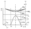
도 3a는 바디(MBk)와 반사면(MSk)을 갖는 미러(Mk)와 같은 반사 광학 소자의 측면도를 개략적으로 나타낸다. 미러(Mk)는 공간 온도 분포 T(x,y,z)를 갖는다. 미러 바디(MBk)가 제로 크로스 온도를 갖는 재료를 포함하면, 통상적으로 온도 분포 T(x,y,z)는 제로 크로스 온도와 상이하다. 온도 분포가 일정한 값 △T 만큼 변화하면, 예를 들면, 제로 크로스 온도에 가까이 상승하면, 예를 들면, 기울기(a2)(CTE(T) = a2 (T-T2 0) 근사에서)가 네가티브인 온도 영역에서 Zerodur®가 사용되면, 미러는 바디(MBk *)를 갖는 미러(Mk *)로 팽창한다. 그러나, 제1 근사에서 팽창에도 불구하고, 면(MSk)의 면 형태의 형상이 변화하지 않지만, 팽창된 미러(Mk *)의 면(MSk *)의 위치가 변화한다. 예를 들면, 도시된 것같이, △z값 만큼 z 방향으로 시프트된다. 이러한 반사면의 위치 변화는 가열된 미러(Mk *)의 병진 운동에 의해 쉽게 보정될 수 있다. 이 경우에, 이미지 결함 또는 광 수차는 거의 변화하지 않는다.3A schematically shows a side view of a reflection optical element such as a mirror MB k and a mirror M k having a reflection surface MS k . The mirror M k has a spatial temperature distribution T (x, y, z). When the mirror body MB k comprises a material having a zero crossing temperature, the temperature distribution T (x, y, z) is typically different from the zero crossing temperature. When the temperature distribution is changed by a predetermined value △ T, for example, when close to the rising zero cross temperature, for example, the inclination (a2) has a negative temperature (CTE (T) = a2 (
도 3b는 온도 분포 T(x,y,z) = TRef (기준 온도로 칭함)를 갖는 미러(Mk)의 상태를 개략적으로 나타낸다. 또한, 실시예와 같이, 최대 온도(△Tmax)를 갖는, 기준 온도(TRef)에 더해진 온도 프로파일 또는 온도 분포 △T(x)에 의해 도시된 것같이, 미러는 미러 바디(MBk)의 x 방향을 따라서 x1에서 x2까지의 표면 영역에서 국부적으로 가열된다. 이 경우, 기준 온도(TRef)는, 이 온도에서 미러가 기준 형상을 갖고 또한 그 반사면(MSk)이 기준 면 형태를 갖는다는 것을 의미한다. 열 팽창으로 인한 편차는 이들 기준 형상과 면 형태에 관계한다. x 방향에서 미러 바디의 치수와 비교하여 간격 [x1, x2]이 작다고 더 가정된다. 미러 바디가 기준 온도(TRef)로 부터 온도 프로파일 △T(x) 만큼 가열되고, 도 2a 및 2b에 도시된 것같이 Zerodur® 또는 ULE®과 같이 온도(T0)에서 제로인 열 팽창의 온도 종속 계수를 갖는 재료로 만들어지고, 실시예로서, 미러 바디의 최대 온도가, 제로 크로스 온도(T0) 아래이고 가열로 인해 기준 온도(TRef) 위인 TRef + △Tmax로 주어지면, 좌표 x1과 x2 사이의 미러의 반사면은 기준 온도에서의 표면과 비교하여 축소된다. 이것은 예를 들면 ULE®가 사용되는 경우이다. 도 3b에서 면 형태의 변화는, 기준 온도(TRef)에서 기준 면 형태(MSk)와 비교될 수 있는 MSk *에 의해 개략적으로 도시된다. L1과 L2는 x 방향에서 바디의 길이가 L0(TRef) = (L2-L1)가 되는 기준 온도에서 바디의 좌표T(x,y,z) = TRef를 나타낸다. 이 변형을 도 3c를 참조하여 보다 상세히 설명한다.Fig. 3B schematically shows the state of the mirror Mk with the temperature distribution T (x, y, z) = T Ref (referred to as reference temperature). Further, as shown by the temperature profile or temperature distribution DELTA T (x) added to the reference temperature T Ref , which has the maximum temperature DELTA Tmax , as in the embodiment, the mirror reflects the temperature of the mirror body MBk and is locally heated in the surface region from x1 to x2 along the x direction. In this case, the reference temperature T Ref means that at this temperature the mirror has the reference shape and its reflecting surface MS k has the reference surface shape. Deviations due to thermal expansion are related to these reference shapes and surface shapes. it is further assumed that the interval [x1, x2] is small in comparison with the dimension of the mirror body in the x direction. The mirror body is heated by the temperature profile DELTA T (x) from the reference temperature (T Ref ), and the temperature dependence of the thermal expansion at zero temperature (T 0 ), such as Zerodur® or ULE® as shown in Figures 2a and 2b made of a material having a coefficient, by way of example, the maximum temperature of the mirror body, a zero-crossing temperature (T 0) is below the reference temperature due to the heat (T Ref) ranking T Ref Given by + Tmax , the mirror's reflective surface between coordinates x1 and x2 is reduced compared to the surface at the reference temperature. This is the case, for example, when ULE® is used. 3B is schematically illustrated by the MS k * which can be compared with the reference surface shape MS k at the reference temperature T Ref . L1 and L2 indicate the coordinates of the body T (x, y, z) = T Ref at the reference temperature at which the length of the body in the x direction becomes L 0 (T Ref ) = (L 2 -L 1). This modification will be described in more detail with reference to FIG.
도 3c는 ppb(parts per billion, 10-9의 값의 의미) 단위의 온도의 함수로서 길이 L0를 갖는 바디(MBk)의 길이의 상대 변화 △L/L0(도 3b와 연결해서 설명된 것같이)를 개략적으로 나타낸다. 기준 온도로서 TRef = 22℃가 선택된다. 이것은 길이(L0)가 22℃에서의 길이를 의미한다. 제로 크로스 온도(T0k)는, 일 예로서, 기준 온도보다 높은 3K인 25℃로 설정되며, 곡선 301은 ULE®에 대한 상대 길이 변화를 개략적으로 나타내고, 곡선 302은 대략 25℃에서 제로 크로스 온도(T0)를 가지고, CTE 근사 CTE(T) = a1 * (T - T0)에 대해 네가티브 기울기 a1를 가지도록 선택된 Zerodur® 재료에 대한 상황을 개략적으로 나타낸다. 예를 들면, 미러 바디(MBk)가 ULE®로 만들어지고, 미러 바디의 온도가 온도 간격 TRef와 (2T0k - TRef) 내에서 선택되면, 미러 바디는 기준 온도에서 바디에 대해 축소된다. 미러 바디가 Zerodur®으로 만들어지는 경우, 곡선 302 참조, 미러 바디는 도 3c로부터 알 수 있듯이, 기준 온도에서 바디에 대해 팽창한다. 미러 면이 도 3b에 도시된 것과 유사한 온도 프로파일을 가지면, (제1 근사에서) L1과 x1 사이의 미러 면 영역은 열 팽창으로 인해서 변화하지 않는다. 또한, 그 이후에 x2와 L2 사이의 영역에서, 온도는 기준 온도에 있거나 거기에 근접한다. x1과 x2 사이의 영역에서, 온도는 기준 온도와 다르기 때문에, 미러 바디는 팽창 또는 수축한다. 이 영역에서 팽창 또는 수축이 발생하는지는 재료와 절대 온도 프로파일(△T(x) +TRef)의 상대 위치 및 서로에 대한 제로 크로스 온도(T0k)에 의존한다. 온도 프로파일의 평균 온도 △Tav는, 적분 한계 x1와 x2를 갖는 △Tav = (∫△T(x)dx|x2 x1)/(x2-x1)이다. 절대 온도 프로파일(△T(x) +TRef)이 대략 제로 크로스 온도(T0k)와 동일하면, 간격 [x1, x2]의 팽창 또는 수축이 없다. 그러나, 이 간격에서, 온도 프로파일 △T(x)의 국부 온도 변화가 있으면, 이 간격보다 더 낮은 스케일에서 가능한 면 변형(도 3b에 비도시)이 여전히 있다. Tav + TRef = T0k인 경우에, 면 형태 변형이 최소화되고, 간격 [x1, x2]의 스케일에서 무시될 수 있다. 이 경우에 수차 또는 이미지 결함이 최소화된다. 다른 경우에 평균 온도가 제로 크로스 온도가 아니고, 미러 바디(MBk)가 간격 [x1, x2] 내에서 수축하면, 반사면의 면 형태는 도 3b에 개략적으로 도시된 것같이 변화하며, MSk *로 표시된다. 팽창의 경우에, 반사면은 MSk **으로 변화하여, 면 형태의 변화를 가져 온다. 모든 경우에, 수차와 이미지 결함이 증가한다. 도 3b에서, 실시예로서, 절대 평균 온도는 제로 크로스 온도 아래이지만 기준 온도(TRef)와 2T0 - TRef로 주어진 온도 내에 있어서, 도 3a의 미러 바디(MBk)에 대해서, ULE®에 대한 면 변형 MSk *을 가져 오고, Zerodur®에 대한 면 변형 MSk **을 가져 온다. 미러가 대략 온도 T = (2T0 - TRef)에 균일하게 향해지면, 미러는 기준 온도(TRef)에서와 동일한 치수와 면 형태를 가지며, 가열에 의해 생긴 추가적인 수차 또는 이미지 에러를 가져 오지 않는다. 상기의 수차에 대한 열 팽창의 영향의 간략한 설명에서는, 오직 x 방향에서 온도 변화가 있고, 다른 수치들은 기준 온도(TRef)에 유지되고, 미러 바디가 제로 크로스 온도에서 변화가 없는, 즉, 제로 크로스 온도가 미러의 x, y 및 z-방향에서 변화하지 않는 것을 의미하는, 재료로 만들어진다는 가정에서, 특별한 온도 프로파일과 같은 다양한 단순화가 행해진다. 실제적인 설계에서, 보다 복잡한 시뮬레이션 계산 또는 유한한 소자 계산이, 반사면 및 제로 크로스 온도 또는 주어진 열 부하 하에서 동작하는 미러의 동작 온도와 같은 다른 미러 파라미터를 최적화하기 위해 필요하다.Figure 3c is described in connection with the ppb (parts per billion, 10 -9 means of the value of) the length of the relative change △ L / L 0 (FIG. 3b as a function of the temperature of the unit length of the body (MB k) with L 0 As shown in FIG. T Ref = 22 deg. C is selected as the reference temperature. This means the length (L 0 ) at 22 ° C. The zero cross temperature T ok is set at 25 ° C, which is, by way of example, 3K higher than the reference temperature,
본 발명에 따르면, 미러 또는 반사 광학 소자의 기준 온도 TRef(x,y,z)와 상이한 절대 온도 프로파일 △T(x,y,z) + TRef이 대략 제로 크로스 온도(T0)에 대해서 대칭이 되도록 미러의 동작 온도 및 제로 크로스 온도가 선택된다. 일차원, 예를 들면, x 방향에 대해서, 이것은 △Tav+ TRef = (∫△T(x)dx|x2 x1)/(x2-x1)+ TRef = T0를 의미한다.According to the invention, with respect to the mirror or reference temperature of the reflective optical element T Ref (x, y, z) with different absolute temperature profile △ T (x, y, z) + T Ref is approximately zero crossing temperature (T 0) The operating temperature and zero cross temperature of the mirror are chosen to be symmetrical. One-dimensional, for example, with respect to the x direction, which △ T av + T Ref = | Means (∫ △ T (x) dx x2 x1) / (x2-x1) + T Ref =
온도 프로파일(△T)이 일차원보다 많은 차원에서 변화하면, 예를 들면, △T = △T(x,y,z), 평균 온도를 얻기 위해 각 차원에서 적분이 행해지며, Tav = (∫∫∫△T(x,y,z) dxdydz|x2 x1|y2 y1)|z2 z1)/(x2-x1)/ (y2-y1)/ (z2-z1)을 의미하며, y1, y2와 z1, z2는 y 및 z-방향에서 각각의 미러 에지이다. 또는, 각 차원에 대한 평균 온도는 개별적으로 계산된다. 이 경우, 제로 크로스 온도에 대한 최적화가 개별 평균 온도 또는 차원, 또는 수차에 가장 관련된 차원에 관련된 2개의 개별 평균 온도에 대해 행해질 수 있다.Temperature profile (△ T) when changes in the number of dimensions than the one-dimensional, e.g., △ T = △ T (x , y, z), to get the average temperature at which the said integration is performed in each dimension, T av = (∫∫∫ △ T (x, y, z) dxdydz | x2 x1 | y2 y1) | z2 z1) / ( mean x2-x1) / (y2- y1) / (z2-z1), and y1, y2 and z1, z2 are the respective mirror edges in the y and z-directions. Alternatively, the average temperature for each dimension is calculated separately. In this case, optimization for the zero cross temperature can be made for the individual mean temperature or dimension, or for two individual mean temperatures related to the dimension most relevant to the aberration.
또한, 본 발명에 따라서, 제로 크로스 온도의 최적화가, 제로 크로스 온도를 갖는 EUV 투영 렌즈의 각 미러에 대해서 예상되는 절대 평균 온도 △Tav + TRef = T0에 대해서 적응될 수 있다. 또는, 예상되는 절대 평균 온도는, 예를 들면 가열 수단으로 적어도 일 차원에서 미러 바디를 균일하게 가열함으로써 미러 재료의 제로 크로스 온도로 균일하게 상승된다. 후자의 방법은 보다 유연성을 제공하므로, 뒤에서 논의되며, 이 방법이 바람직하다.Further, in accordance with the present invention, the optimization of the zero crossing temperature is made possible by using the absolute average temperature < RTI ID = 0.0 > Tav < / RTI > for the respective mirrors of the EUV projection lens with zero- + T Ref = T 0 . Alternatively, the expected absolute average temperature is uniformly raised to the zero crossing temperature of the mirror material, for example by heating the mirror body uniformly, at least in one dimension, by heating means. The latter method provides more flexibility and is discussed later, and this method is preferred.
도 3d ~ 3f는 투영 렌즈(20) (도 1)에서 사용된 것으로서 EUV 미러의 보다 실제적인 온도 분포를 나타낸다. 도 3d에서, 그 치수를 갖는 미러 Mk가 위로부터 보여진다. 이 미러의 온도 분포와 각각의 수차의 시뮬레이션을 위해서, 6개의 미러(k=1 ~ 6)를 갖는 EUV 투영 렌즈가 사용되었다. 투영 빔의 방향으로 세어서 레티클 이후에 제4 미러인 미러(24(도 6 참조) 또는 M4)에 대한 결과가 도 3d ~ 3f에 도시되어 있다. 6개 미러를 갖는 EUV 렌즈가 아래에 도시 및 설명되어 있다. 도 3d에서, 온도 분포가 그레이 셰이딩 패턴으로 도시된다. 온도는 미러 주위로부터 기준 온도(TRef)인 22℃로부터 중간의 블랙 스폿에서 대략 TRef + △Tmax(x) = 24℃까지 증가한다. 도 3e는 최대 온도 △Tmax를 통해서 x 방향에 따른 미러의 온도 프로파일 △T(x)로서 기준 온도에 대한 온도 차를 나타낸다. 도 3f는 최대 온도 △Tmax를 통해서 y 방향에 따른 미러의 온도 프로파일 △T(x)로서 기준 온도에 대한 온도 차를 나타낸다. 미러의 불균일한 온도 프로파일은 상기 설명한 것같이 미러면의 변형을 가져 온다. 이들 변형은 수차에 영향을 주어 이미지 에러 또는 결함을 발생시킨다. 미러 M4에 대한 제르니케 계수의 값이 주어진 도 3g에 도시되어 있다. 이들 계수는 이미지 포인트(IP)를 생성하는 이미지 면에서 이상적인 구형 파면의 편차에 대한 양 또는 측정치이다(도 1 참조).Figs. 3d to 3f show a more practical temperature distribution of the EUV mirror as used in the projection lens 20 (Fig. 1). In Fig. 3D, a mirror M k with that dimension is seen from above. For the simulation of the temperature distribution of this mirror and each aberration, an EUV projection lens with six mirrors (k = 1 to 6) was used. The results for mirrors 24 (see FIG. 6) or M 4 , which are the fourth mirrors after the reticle in the direction of the projection beam, are shown in FIGS. 3d through 3f. An EUV lens with six mirrors is shown and described below. In Figure 3D, the temperature distribution is shown in a gray shading pattern. The temperature increases from 22 deg. C, which is the reference temperature (T Ref ), to about T Ref + Tmax (x) = 24 deg. C in the middle black spot from around the mirror. Fig. 3E shows the temperature difference with respect to the reference temperature as the temperature profile DELTA T (x) of the mirror along the x direction through the maximum temperature DELTA Tmax . Fig. 3F shows the temperature difference with respect to the reference temperature as the temperature profile DELTA T (x) of the mirror along the y direction through the maximum temperature DELTA Tmax . The non-uniform temperature profile of the mirror leads to deformation of the mirror surface as described above. These deformations affect the aberration and cause image errors or defects. The value of the Zernike coefficient for the mirror M 4 is shown in Figure 3g given. These coefficients are an amount or a measure of the deviation of the ideal spherical wavefront from the image plane producing the image point (IP) (see FIG. 1).
제르니케 계수를 얻기 위해 파면은 일련의 제르니케 함수에서 팽창된다. 이상적인 구형 파는 제1 제르니케 계수 만을 갖고, 모든 다른 계수는 0이다. 그래서 2보다 큰 제르니케 계수의 값은 다양한 촬상 에러에 대한 측정치이며, 이들 계수가 클 수록 광학적 촬상 시스템에서 광 수차가 커진다.To obtain Zernike coefficients, the wavefront is expanded in a series of Zernike functions. The ideal spherical wave has only a first Zernike coefficient and all other coefficients are zero. Thus, the value of the Zernike coefficient larger than 2 is a measure for various imaging errors, and as these coefficients become larger, the optical aberration becomes larger in the optical imaging system.
도 3g에서 각각의 제르니케 계수에 대해서 2개의 값이 주어진다. 좌측 값(바)은 미러의 추가 가열이 없을 때의 값이다. 우측 바에 의해 주어진 우측 값은 미러의 추가적인 균일한 가열을 갖는 값이다. 이것을 보다 상세히 설명한다. 이 예에서 미러 M4는 25℃의 제로 크로스 온도를 갖는 ULE®로 만들어진 미러 바디를 갖는다. 기준 온도는 TRef = 22℃이다. 이것은 EUV광이 없이, 미러의 온도가 22℃에 있다는 것을 의미한다. 바람직하게, 이 온도에서 수차가 최소화된다. 오브젝트 포인트 OP를 이미지 포인트 IP로 투영하기 위해 EUV 광이 온으로 스위칭되면, 미러는 가열되고, 도 3g에서 각각의 좌측 바로 표시된 것같이 수차가 발생한다. EUV 광이 온으로 스위칭되기 전에 미러 M4가 2℃만큼 추가적으로 균일하게 가열되어 24℃가 되면, EUV 광이 온으로 스위칭된 후에 수차는 좌측 바보다 현저하게 낮은 우측 바를 생기게 한다. 이것은 적어도 하나의 렌즈 미러를 균일하게 가열함으로써 EUV 렌즈의 수차가 현저하게 감소될 수 있는 것을 의미한다.In Figure 3g two values are given for each Zernike coefficient. The left value (bar) is the value when there is no additional heating of the mirror. The right value given by the right bar is a value with additional uniform heating of the mirror. This will be described in more detail. In this example, the mirror M 4 has a mirror body made of ULE® with a zero cross temperature of 25 ° C. The reference temperature is T Ref = 22 ° C. This means that without EUV light, the temperature of the mirror is at 22 占 폚. Preferably, aberrations are minimized at this temperature. When the EUV light is switched on to project the object point OP to the image point IP, the mirror is heated and an aberration occurs as indicated on each left side in Figure 3g. When the mirror M 4 is further uniformly heated by 2 캜 to 24 캜 before the EUV light is switched on, the aberration causes a significantly lower right bar than the left bar after the EUV light is switched on. This means that the aberration of the EUV lens can be remarkably reduced by uniformly heating at least one lens mirror.
도 3h ~ 3l은 투영 렌즈(20) (도 1)에서 사용되는 것같이 EUV 미러의 더 실제적인 온도 분포를 나타낸다. 도 3h에서, 도 6의 EUV 투영 렌즈의 미러 M6는 도 3d와 유사하게 도시된다. 이 미러와 각각의 수차의 온도 분포의 시뮬레이션을 위해서, 6개의 미러를 갖는 EUV 투영 렌즈가 도 3d~3g에 대해서, 도 6에 도시된 것같이 사용된다. 결과는 투영 빔의 방향으로 세어서 레티클 뒤에서 제6 미러를 의미하는 미러 26 (도 6 참조) 또는 M6에 대해서 도 3h ~ 3l에 도시된다. 온도는 미러 주위로부터 기준 온도(TRef)인 22℃로부터 좌우 블랙 스폿의 중간에서 대략 1.2℃ 까지 증가한다. 도 3i는 기준 온도에 대한 온도 차 △T(x) = T(x) - TRef가 주어지는 최대 온도를 통해서 x 방향에 따른 온도 프로파일을 나타낸다. 도 3k는 x 방향에서 최대 값들 사이에서 최소 온도를 통한 y 방향에 따른 기준 온도에 대한 온도 차 △T(y) = T(y) - TRef를 나타낸다. 미러의 불균일 온도 프로파일은 미러 면의 변형을 다시 가져 온다. 이 미러에 대한 제르니케 계수에 대한 값이 도 3l에 주어진다. 좌측 값 (바) 이득은 미러의 추가 가열을 갖지 않을 때의 값이다. 우측 값은 미러의 추가 가열이 있을 때의 값이다. 미러(M6)는 25℃의 제로 크로스 온도를 갖는 ULE®로 만들어진 미러 바디를 갖는다. 기준 온도는 TRef = 22℃이다. 이것은 EUV광이 없이, 미러의 온도가 22℃에 있다는 것을 의미한다. 바람직하게, 이 온도에서 수차가 최소화된다. 예를 들면, 오브젝트 포인트 OP를 이미지 포인트 IP로 투영하기 위해 EUV 광이 온으로 스위칭되면, 미러는 가열되고, 도 3l에서 각각의 좌측 바로 표시된 것같이 수차가 발생한다. EUV 광이 온으로 스위칭되기 전에 미러 M6가 3.8℃만큼 추가적으로 균일하게 가열되어 25.8℃가 되면, EUV 광이 온으로 스위칭된 후에 수차는 좌측 바보다 현저하게 낮은 우측 바를 생기게 한다. 이것은 투영 렌즈중 적어도 하나의 렌즈 미러를 균일하게 가열함으로써 EUV 렌즈의 수차가 현저하게 감소될 수 있는 것을 또한 의미한다.Figures 3h-3l illustrate a more practical temperature distribution of the EUV mirror as used in the projection lens 20 (Figure 1). In Figure 3h, the
도 4를 참조하여 미러 실정을 갖는 미러의 보다 상세한 설명과 기준 온도(TRef)를 보다 상세히 설명한다. 도 1 또는 도 6을 참조하여 상기 서술된 것같이 투영 렌즈(20)는 미러 21, 22, 23, 24 (25, 26) 또는 일반적으로 복수의 반사 광학 소자(Mi)를 포함하고, 각각은 레티클 또는 구조화된 오브젝트(M) 상의 오브젝트 필드의 적어도 하나의 오브젝트 포인트(OP)를 50 nm 미만의 파장 범위의 파장을 갖는 EUV 광의 노광 파워로 투영 렌즈(20)가 노광되면 기판 또는 웨이퍼(W) 상의 이미지 필드의 이미지 포인트(IP)로 투영하기 위한 바디(MBi)와 반사면(MSi)을 가진다. 바람직하게, 대략 13 nm의 파장이 사용된다. EUV 리소그래피 투영 노광 시스템(100)의 조명 시스템(10)에 의한 조명 후 레티클(M)로부터 EUV 광이 반사된다. 또한, 투영 렌즈(20)는 반사 광학 소자(Mi)(예를 들면 미러 21, 22, 23, 24)를 수동적으로 또는 능동적으로 지지하는 지지 구조를 포함한다. 지지 구조 또는 지지 구조의 일부의 온도는 기준 온도(TRef)에 있다. 이것은 EUV 리소그래피 투영 노광 시스템(100) (도 1)에서 사용되는 복수의 반사 광학 소자(Mi)로부터 하나의 반사 광학 소자(Mk)를 나타내며, 예를 들면 WO 2005/026801 A2에 서술된 것같이, 미러(421)용 미러 마운팅 어셈블리(400)를 개략적으로 나타내는 도 4에 보다 상세히 도시되어 있다. 미러(421)는 Zerodur® 또는 ULE®로 만들어지거나, 예를 들면 재료 Zerodur® 또는 ULE® 중 하나를 포함하는 재료로 만들어거나, 또는 적어도 하나의 제로 크로스 온도를 갖는 재료로 만들어지는 미러 바디(MBk)를 포함한다. 미러(421)는 EUV광의 투영 빔(4) (도 1)의 반사율을 개선하기 위해 소정 층 두께를 갖는 소정의 층 재료의 선택적인 다층을 갖는 반사면(450)을 또한 포함한다. 미러 바디(MBk)는 지지 소자(480)에 의해 지지된다. 일 예로서, 미러(421)는 3개의 마운팅 또는 연결 포인트(451, 452, 453)에 의해 지지되거나 서스펜드된다. 각각의 실장 포인트에서, 기생력 및/또는 모멘트가 지지 소자(480)로부터 미러로 거의 전달되지 않도록 미러(421)를 보유하는 운동 마운트를 얻기 위해, 미러 바디(MBk)는 양각대 구조(461, 462, 463)을 갖는 연결 소자(471, 472, 473)와 연결된다. 일반적으로 그러나 필수적이지는 않게, 양각대 구조중 적어도 하나는 가동 장치를 포함한다. 지지 소자(480)는 투영 렌즈(20)의 하우징 구조에 고정된다. 하우징 구조은 때때로 투영 광학 박스 즉, POB로 불려진다. 본 발명에 따라서, 다음의 소자들 중 소정의 또는 제어된 기준 온도(TRef)를 갖는 지지 구조로서, 다음의 소자들이 바람직하게 선택된다: 연결 포인트(451, 452, 453), 연결 소자(471, 472, 473), 양각대 구조(461, 462, 463), 지지 소자(480) 또는 하우징 구조(481). 선택된 지지 구조는 다른 것들 중에서 EUV 리소그래피 노광 시스템에서 사용되는 온도 제어 시스템에 의존한다. 이로 인해, 도 4에서 모든 소자들은 TRef로 지정되어 있지만, 이것은 이들 모든 소자들이 투영 시스템(100)의 동작 동안 동일한 온도를 갖는 것을 의미하지는 않는다.A more detailed description of the mirror having the mirror reality and the reference temperature T Ref will be described in more detail with reference to FIG. As described above with reference to Figures 1 or 6, the
본 발명에 따르면, 기준 온도(TRef)는 EUV 광이 오프로 스위칭되는 EUV 리소그래피 노광 시스템의 동작 모드에서, 또는 EUV 광의 파워가 EUV 리소그래피 노광 시스템의 대량 생산 동작 모드에서 레티클 상의 오브젝트 필드를 기판 상의 이미지 필드로 투영하기 위해 일반적으로 사용되는 노광 파워의 대략 10%보다 적은 동작 모드에서, 반사 광학 소자(421)를 지지하는 선택된 지지 소자의 온도이다. 이 기준 온도(TRef)는 투영 렌즈(20)가 동작되는 클린 룸의 실온에 가깝게 일반적으로 선택되며, 이것은 기준 온도가 대략 20℃ ~ 24℃의 범위, 바람직하게 22℃인 것을 의미한다. 대부분의 EUV 리소그래피 투영 노광 시스템에서, 추가의 온도 제어 시스템은 투영 렌즈(20)의 동작 동안에도 이 온도가 일정하도록 기준 온도(TRef)를 제어한다. 일반적으로 이것은 하우징 구조(481) 및/또는 지지 소자(480) (도 4)의 온도가 도 3에서 선택된 것같이, 예를 들면 22℃에 있는 것을 의미한다. 본 발명에 따르면, 제로 크로스 온도(T0k)가 기준 온도보다 높도록 바람직하게 온도가 선택된다. 이것은 제로 크로스 온도 근방에서 미러를 동작시키기 위해 기준 온도(TRef) 아래의 온도로 냉각될 필요는 없다는 장점을 가진다. EUV 투영 렌즈에서 미러의 냉각을 회피하기 위해서, 미러의 냉각이 기술적으로 어렵거나 비싼 진공에서 렌즈에서 동작하기 때문에 투영 렌즈가 유리하다.According to the present invention, the reference temperature (T Ref ) can be adjusted in an operating mode of the EUV lithography exposure system in which the EUV light is switched off, or in a mass production mode of operation of the EUV lithography exposure system, Is the temperature of the selected supporting element supporting the reflective
또한, 본 발명에 따라서, 투영 렌즈(20)는 적어도 하나의 광학 소자(Mk)를 가열하기 위한 히터(300)를 포함하며, 또한 도 4와 동일한 도면 부호가 동일하거나 또는 유사한 부분을 나타내는 도 5에 도시된 것같이, 적어도 하나의 광학 소자(Mk)의 온도를 온도(Tk)로 제어하는 온도 제어 시스템(200)을 포함한다. 가열가능한 광학 소자(Mk)에서, 투영 렌즈가 노광 파워로 노광될 때 및 히터(300)가 가동 또는 가열되지 않으면, 기준 온도에 대한 공간적인 온도 분포 △T(x,y,z) = (T(x,y,z)- TRef)가 형성된다. 이 분포는 상기 정의된 것같이 평균 온도 △Tav를 갖는다.Also according to the present invention, the
적어도 하나의 가열된 광학 소자(Mk)는 도 4에 도시된 것과 동일한 방식으로 지지 구조에 연결될 수 있다. 또한, 적어도 하나의 가열된 반사 광학 소자(Mk)의 미러 바디(MBk)는 기준 온도(TRef) 보다 높은 온도(T0k)(이 온도도 제로 크로스 온도로 칭해진다)에서 제로인 열 팽창의 온도 종속 계수를 갖는 재료를 포함한다. 바람직한 기준 온도 TRef = 22℃로 인해서, 바람직한 제로 크로스 온도(T0k)가 22℃와 대략 70℃ 사이에 있다. 이미 위에 서술된 것같이, 이러한 재료들은 예를 들면 Zerodur® 또는 ULE®이다. 제로 크로스 온도(T0k) 및 기준 온도(TRef)에 대한 적어도 하나의 온도 제어된 또는 가열가능한 광학 소자(Mk)의 온도(Tk)의 관계는, Tk = T0k- △Tav ; Tk =2*T0k - TRef -△Tav ; Tk =TRef + 3*(T0k - TRef)/2 -△Tav ; Tk = T0k- △Tmax ; Tk = 2*T0k - TRef -△Tmax ; Tk = TRef + 3*(T0k - TRef)/2 -△Tmax로 구성되는 군에서 Tk가 선택되도록 한다. 광학 소자(Mk)상의 온도 분포 △T(x,y,z)의 형성 전에 이 온도(Tk)가 바람직하게 선택되는 반면, 투영 시스템의 동작 모드 동안 광학 소자가 EUV 광을 받을 때 가열로 인해 온도 분포가 생긴다. 이것은 반사 소자(Mk)가 제로 크로스 온도에 근접하므로 미러 또는 반사 소자(Mk)에 의해 흡수되는 투영 빔의 EUV 광이 대략 제로 크로스 온도까지 가열되는 장점을 갖는다. 본 발명의 장점은, 히터(300)를 적용하여 투영 처리 동안 바람직한 제로 크로스 온도에서 미러가 동작가능하므로 제로 크로스 온도가 매우 자유롭게 선택될 수 있다는 것이다. 선택적으로, △Tav가 대략 1K와 같이 작으면, Tk는 또한 제로 크로스 온도 T0가 될 수 있다.At least one heated optical element Mk may be connected to the support structure in the same manner as shown in Fig. Moreover, the mirror body (MB k) of at least one of the heat reflection optical element (M k) is the thermal expansion is zero at the reference temperature, a temperature greater than (T Ref) (T 0k) ( referred to as the temperature is also zero-crossing temperature) Lt; RTI ID = 0.0 > temperature-dependent < / RTI > Due to the preferred reference temperature T Ref = 22 占 폚, the preferred zero crossing temperature ( T0k ) lies between 22 占 폚 and approximately 70 占 폚. As already described above, these materials are, for example, Zerodur® or ULE®. Zero-cross relationship between the temperature (T 0k) and the reference temperature (T Ref) temperature (T k) of the optical element (M k) at least one possible temperature control of the heating or for the, T k = T 0k -? T av ; T k = 2 * T 0k - T Ref -? T av ; T k = T Ref + 3 * (T 0k - T Ref ) / 2 -? T av ; T k = T 0k -? T max ; T k = 2 * T 0k - T Ref -? T max ; T k = T Ref + 3 * (T 0k - T Ref) / 2 - and a T k from the group consisting of △ T max is selected. This temperature T k is preferably selected before the formation of the temperature distribution AT (x, y, z) on the optical element M k , Resulting in a temperature distribution. This has the advantage that the reflection device (M k) is heated up to zero, so close to the temperature of the mirror or reflective element cross EUV light is approximately zero crossing temperature of the projection beam is absorbed by the (M k). An advantage of the present invention is that the zero cross temperature can be selected very freely since the mirror can be operated at the desired zero cross temperature during the projection process by applying the
이것은 온도(Tk)가 히터(300) (도 5 참조)에 의해 이러한 온도로 온도 제어 시스템(200)에 의해 제어되는 것을 의미한다. 바람직하게, 히터는 미러(Mk)를 이러한 일정한 온도 값으로 균일하게 가열한다. 온도(Tk)는 EUV 광의 힘이 오프인 EUV 리소그래피 노광 시스템의 동작 모드에서 미러(Mk)의 동작 온도이다. EUV 광의 파워는 리소그래피 노광 시스템의 대량 생산 동작 모드에서 레티클 상의 오브젝트 필드를 기판상의 이미지 필드로 투영하기 위해 일반적으로 사용되는 노광 파워로 스위칭되면, 반사 광학 소자 또는 미러(Mk)의 온도는 제로 크로스 온도(T0)에 또는 거기에 근접하게 평균 온도 △Tav만큼 증가한다. 상기 서술된 것같이, 바람직하게 온도(Tk)는 EUV 광이 온으로 스위칭되기 전의 값으로 이미 제어된다. 바람직한 실시예에서, 미러(Mk)가 받는 열적 에너지가 일정하도록 히터가 제어된다. 이것은 예를 들면, 미러가 일부의 다른 에너지, 예를 들면 일부의 EUV 광을 흡수하면, 미러로의 열적 에너지의 전체 입력이 시간상 일정하도록 히터가 그 가열 파워를 감소시킨다는 것을 의미한다. 이것은 미러의 평균 온도도 시간상 일정하거나 또는 거의 일정하게 한다. Tk의 다양한 바람직한 값에 대해 보다 상세히 설명한다.This means that the temperature T k is controlled by the
온도(Tk)는 반사면(MSk) 또는 미러 바디(MBk)에서 제어될 수 있다. 온도들(T0k)(제로 크로스 온도)사이의 상기 주어진 관계에서, 미러(MK)(또는 일반적으로 반사 광학 소자)의 동작 온도(Tk)와 평균 온도(△Tav)뿐 아니라 지지 구조의 기준 온도(TRef)는 가장 실제적인 경우에 있어서 반사 광학 소자(Mk)의 매우 작은 길이 변화 또는 면 형태 변화를 가져 오고, 수차 또는 이미지 에러가 현저하게 감소되며, 도 3g와 3l에 도시된 것같이, 대략 Tk = T0k- △Tav와 Tk =TRef + 3*(T0k - TRef)/2 -△Tav가 되도록 온도(Tk )가 제어된다.The temperature T k can be controlled in the reflective surface MS k or the mirror body MB k . In the given relationship between the temperatures T ok (zero cross temperature), the operating temperature (T k ) and the average temperature (ΔT av ) of the mirror M K (or generally the reflective optical element) The reference temperature T Ref of the reflective optical element M k leads to a very small change in length or a change in the surface shape of the reflective optical element M k in the most practical case and aberration or image error is significantly reduced, As it is, approximately T k = T 0k -? T av and T k = T Ref + 3 * (T 0k - T Ref) / 2 - △ temperature (T k such that T av Is controlled.
수식 Tk =TRef + 3*(T0k - TRef)/2 -△Tav는 미러 면위에서뿐 아니라 미러의 두께 또는 z 방향으로 온도 분포가 있는 것을 고려한다. 반사면의 측면 위에, 예를 들면, 미러의 주변에서 온도(Tk)가 있고, 미러의 후면에 예를 들면, 이 온도에서 지지 구조의 임의의 열적 조건으로 인한 기준 온도(TRef)가 있다고 가정하면, Tk에 대한 양호한 온도가 Tk =2*T0k - TRef - △Tav에 의해 주어진다. 그러나, 온도 제어 시스템의 정확성 또는 온도(Tk)가 제어 가능한 정확성이 수차 또는 촬상 에러에 영향을 준다. 온도 제어 및 다른 시스템 변동으로 인해서 반사 광학 소자(Mk)의 바디(MBk)의 온도의 정확성이 ±1K 내에 있으면, 도 3c에서 도면 부호 303으로 개략적으로 도시될 수 있는 것같이, 길이의 상대 변화는 대략 10 ppb보다 일반적으로 적다. 그러나, 동작 온도는 대략 TRef + (T0k - TRef )/2 및 TRef + 3*(T0k - TRef)/2 사이에서 선택될 수 있는 것으로 가정한다. 도 3c로부터 알 수 있듯이, 동작 온도가 기준 온도(TRef)에 너무 근접하거나 또는 일반적으로 제로 크로스 온도(T0k)에서 너무 멀면, 도면 부호 304와 305로 나타낸 것같이, 길이의 상대적인 변화는 10 ppb보다 훨씬 많다. 바디(MBk)의 변형으로 인한 미러 변형의 현저한 위험이 있는 경우에, 시스템의 광학적 성능의 변형을 가져 온다. 이로 인해, 특히, 간격 [(TRef + T0)/2 ; TRef + 3*(T0k - TRef)/2]내에 있으면, 동작 온도 Tk = T0k- △Tav 및 Tk = TRef + 3*(T0k - TRef)/2 -△Tav가 바람직하다.The formula T k = T Ref + 3 * (T 0k - T Ref ) / 2 - ΔT av considers that there is a temperature distribution in the thickness or z direction of the mirror as well as on the mirror surface. On the side of the reflecting surface, for example, there is a temperature T k at the periphery of the mirror and a reference temperature T Ref due to any thermal condition of the supporting structure at this temperature, for example at the rear of the mirror Assuming, the preferred temperature for the T k T k = 2 * T 0k - T Ref -? T av . However, the accuracy of the temperature control system or the controllable accuracy of the temperature (T k ) affects the aberration or imaging error. If the temperature accuracy of the body MB k of the reflective optical element M k is within ± 1 K due to temperature control and other system variations, as shown schematically at 303 in Figure 3c, The change is generally less than about 10 ppb. However, it is assumed that the operating temperature can be selected between approximately T Ref + (T 0k - T Ref ) / 2 and T Ref + 3 * (T 0k - T Ref ) / 2. As can be seen from Figure 3c, if the operating temperature is too close to the reference temperature (T Ref ) or generally too far from the zero crossing temperature (T 0k ), the relative change in length, as indicated by
미러 바디(MBk)에 대한 재료의 제로 크로스 온도가 투영 렌즈의 설계를 위해 사용된 임의의 설계 계산 또는 시뮬레이션에 따른 것보다 높도록 재료를 선택하는 것이 바람직하다. 이러한 계산에서, 주위 온도의 변동, 렌즈 설계에 대한 디자인 가정의 변동, EUV 광원, 레티클 반사의 변동이 고려되어, EUV 투영 렌즈가 설계될 때 미러(Mk)의 최대 또는 평균 온도의 계산을 하게 된다. 제로 크로스 온도가 계산된 값보다 몇 켈빈(Kelvin) 높게 선택되면, EUV 렌즈는, 수차가 최소화되는 제로 크로스 온도에 근접한 바람직한 온도에서 모든 조건 하에서, 동작될 수 있다. 미러의 동작 온도가 히터(300)와 컨트롤러(200)에 의해 제어된 균일한 가열에 의해 이루어질 수 있다. 히터(300)에 대해서 다양한 예가 사용될 수 있다. 이 예들은 금속 판으로 만들어지고, 미러에 근접하고, 바람직하게 미러의 후면에 근접하게 배열된 가열 소자들이다. 대안으로서 또는 부가적으로 전기 가열 소자는 미러 바디와 직접 접촉한다. 또 다른 대안으로서 또는 부가적으로 히터는 미러 또는 반사 소자가 조사되는 적외선 소스를 포함한다.It is desirable to select the material so that the zero cross temperature of the material for the mirror body MB k is higher than that according to any design calculations or simulations used for the design of the projection lens. In this calculation, variations in the ambient temperature, variations in the design assumptions for the lens design, variations in the EUV light source, and reticle reflections are taken into account to calculate the maximum or average temperature of the mirror ( Mk ) when the EUV projection lens is designed do. If the zero cross temperature is chosen to be a few degrees Kelvin higher than the calculated value, the EUV lens can be operated under all conditions at a desired temperature close to the zero cross temperature at which aberrations are minimized. The operating temperature of the mirror can be achieved by uniform heating controlled by the
또한, 온도 제어 시스템(200)은 하나의 또는 몇몇 위치에서 미러 온도(Tk)를 직접 측정하는 센서를 포함할 수 있다. 본 발명의 또 다른 실시예에서, 온도 제어 시스템에 의해 제어되는 적어도 하나의 광학 소자(Mk)의 온도(Tk)가 광학 소자(Mk)의 반사면(MSk)(도 5)의 온도(TMSk) 또는 광학 소자(Mk)의 바디(MBk)의 온도(TMBk)일 수 있다. 또 다른 온도(Tk)는 바디(MBk)의 온도(TMBk) 및/또는 반사면(MSk)의 온도의 함수에 주어진 온도일 수 있다. 또한, 반사면의 온도(TMSk)는 평균 면 온도일 수 있다. 이러한 평균화는 예를 들면, 자외선 카메라로 면 온도를 측정하거나 공간-분해 고온계(pyrometer)에 의해 행해질 수 있다. 또한 바디의 온도(TMBk)는 바디(MBk)에서 복수의 공간 위치에서 측정된 복수의 온도의 평균 온도일 수 있다. 바람직하게, 미러 바디의 온도가 측정된 공간 위치 또는 공간 위치의 서브셋은 반사 면에 근접하게 배열된다. 제어기(200)에 의해, 온도 값 또는 제어 파라미터는 반사 면 및/또는 바디의 온도 또는 온도들의 측정으로부터 계산될 수 있다. 또 다른 대안으로서, 상기 서술된 것같이, 제어 시스템에 대한 온도(Tk)는 바디(MBk) 또는 반사면(TMSk)의 공간 온도 분포로부터 선택된다. 광학 소자(Mk)의 온도가 하나 또는 몇몇 위치에서 측정되는지 및 온도 제어 시스템이 온도 신호에 대한 하나 이상의 입력 채널을 포함하는지에 의거하여, 하나의 서술된 온도 제어 옵션이 선택된다. 대안으로서 또는 추가로, 광 수차가 정해질 수 있고, 온도 제어 시스템(200)은 수차가 최소가 되도록 미러 온도를 제어한다. 수차의 온도 제어 또는 제어를 위해서, 온도(Tk)가 반드시 분명하게 결정될 필요는 없다. 또는 모델 기반 제어기는 미러의 온도 또는 미러에 전달되는 히터의 열을 제어한다. 모델은 렌즈가 노광되는 EUV 광의 파워, 레티클이 조사되는 조명 세팅, 레티클 상의 구조 및 렌즈의 광 수차와 같은 파라미터를 고려할 수 있다.In addition, the
또 다른 실시예에서, 조명된 레티클의 EUV 광은 조명 세팅에 따른 각도, 편향 또는 세기의 공간 분포를 포함한다. 이것은 기준 온도(TRef)에 대한 공간 온도 분포 △T(x,y,z) = (T(x,y,z)- TRef)를 가져 온다. 이 온도 분포는 일반적으로 평균 온도(△Tkav)와 최대 온도 △Tkmax= (TRef + △Tkmax)를 가진다. 온도 분포는, 히터를 가열하지 않은 노광 파워로 노광 렌즈가 노광될 때, 가열가능한 광학 소자(Mk)의 반사면(MSk) 상에 만들어진다.In another embodiment, the EUV light of the illuminated reticle comprises a spatial distribution of angles, deflections or intensities as a function of illumination settings. This results in a spatial temperature distribution T (x, y, z) = (T (x, y, z) - T Ref ) for the reference temperature T Ref . This temperature distribution is generally defined as the average temperature ΔTav and the maximum temperature ΔTkmax = (T Ref + DELTA T kmax ). The temperature distribution is created on the reflective surface MS k of the heatable optical element M k when the exposure lens is exposed with unexposed heating power to the heater.
온도 분포의 결정 뒤, 온도(Tk)의 상기 서술된 선택에 대한 대안으로서 또는 추가적으로, 온도(Tk)가 Tk = (T0k + TRef + △Tkmax)/2로서 선택된다. △Tkmax에 의존하여, 제로 크로스 온도가 최대 온도 Tkmax = TRef + △Tkmax보다 높은 경우에, 이 선택은 가열된 광학 소자가 제로 크로스 온도에 근접하게 가열되는 평균을 갖는다. 상기 서술된 것같이, 투영 빔(4)의 EUV 광이 온으로 스위칭되기 전에, Tk는 광학 소자(Mk)의 바디(MBk)의 온도(TMBk), 바디(MBk)의 온도(TMBk)의 함수에 의해 주어진 온도, 및 반사면(MSk)의 온도(TMSk) 또는 반사면(MSk) 또는 바디(MBk)의 공간 온도 분포로부터 선택된 온도일 수 있다.After determination of the temperature distribution, temperature as an alternative to the selection of the above-described (T k) or in addition, the temperature (T k) is selected as T k = (T 0k + T Ref + △ T kmax) / 2. Depending on ΔT kmax , the zero-cross temperature is the maximum temperature T kmax = T Ref + DELTA T kmax , this selection has an average where the heated optical element is heated close to the zero crossing temperature. As described above would, before the EUV radiation of the projection beam (4) is switched on, T k is the optical element temperature of the temperature (T MBk), the body (MB k) of the body (MB k) of the (M k) It may be a temperature selected from the spatial temperature distribution of the temperature (T MSk) or the reflection surface (MS k) or the body (MB k) for a given temperature, and the reflection surface (MS k) by a function of (T MBk).
본 발명에 따른 투영 렌즈의 또 다른 실시예에서, 투영 렌즈가 EUV 광의 노광 파워를 받기 전의 시간에, 광학 소자(Mk)의 온도(Tk)는 제1 가열 파워로 히터를 가열함으로써 그 값으로 제어된다. 이것은, 노광 동안, EUV 광에 의한 노광 전에 광학 소자의 동작 온도(Tk)가 이 동작 온도에 매우 근접하는 장점을 갖는다. 이것은 노광 시간의 함수로서 수차 오차의 변화가 현저하게 감소될 수 있고, 투영 시스템은, 촬상 품질이 거의 변화하지 않는 정적 상태 동작 조건에서 보다 빠르게 된다. 바람직하게, 노광 동안(투영 렌즈가 EUV 광의 노광 파워를 받는 시간 동안) 히터의 가열 파워는 제1 가열 파워보다 적다. 이것은 광학 소자(Mk)의 웜업을 방지한다.In a further embodiment of the projection lens according to the present invention, the temperature (T k) of the time before the projection lens will receive the EUV light exposure power, the optical element (M k) is the value by heating with a heater at a first heating power . This has the advantage that, during exposure, the operating temperature ( Tk ) of the optical element is very close to this operating temperature before exposure by EUV light. This can significantly reduce the variation of the aberration error as a function of the exposure time, and the projection system becomes faster in a static state operating condition in which the imaging quality hardly changes. Preferably, the heating power of the heater is lower than the first heating power during the exposure (during the time when the projection lens receives the exposure power of the EUV light). This prevents warming of the optical element M k .
본 발명에 따른 투영 렌즈의 또 다른 실시예에서, 제2 광학 소자(M2k)를 온도(T2k)로 가열하는 제2 히터가 사용되고, 제2 광학 소자(M2k)의 바디(MB2k)는 기준 온도보다 높은 온도(T02k)에서 제로인 열 팽창의 온도 종속 계수를 갖는 재료를 포함한다. 제2 광학 소자에서, 투영 렌즈가, 평균 온도(△T2av)와 최대 온도(△T2max)를 갖는, 제2 히터를 가열하지 않고 노광 파워로 노광될 때, 기준 온도(TRef)에 대한 제2 공간 온도 분포 △T2(x,y,z) = (T2(x,y,z)- TRef)가 형성된다. 상기 서술된 실시예와 유사하게, 도 3c와 연결하여, 제2 광학 소자(M2k)의 온도(T2k)는 제1 가열된 미러(Mk)의 동작 온도(Tk)에 대해서 상기 서술된 것과 동일한 관계에 따라서 선택된다. 이것은 제2 광학 소자(M2k)의 동작 온도(T2k)가, T2k = T02k -△T2av ; T2k =2*T02k - TRef -△T2av ; T2k =TRef + 3*(T02k - TRef)/2 -△T2av ; T2k = T02k- △T2max ; T2k= 2*T02k - TRef -△T2max ; T2k = TRef + 3*(T02k - TRef)/2 -△T2max로 이루어진 그룹으로부터 바람직하게 선택되는 것을 의미한다. 투영 빔(4)의 EUV 광의 파워가 온으로 스위칭되기 전에 광학 소자 또는 미러(M2k)가 이 온도(T2k)이거나 또는 이 온도로 가열된다. 이 실시예에서, 바디(MB2k)의 재료는 제1 광학 소자의 바디(MBk)의 재료와 동일하거나 또는 상이할 수 있다. 동일한 재료의 제1 경우에, 바람직하게, 재료는 상이한 제로 크로스 온도를 가지며, CTE(T) 함수(도 2b 참조)가 각각의 제로 크로스 온도에서 경사에 대해서 상이한 대수 사인을 가지도록 제1 반사 소자(Mk)가 선택될 수 있다. 이 재료는 Zerodur® 재료에 대해서 도 2b에 나타낸 것같이, 적어도 2개의 제로 크로스 온도(T0, T02)를 포함하는 것이 요구된다. 상이한 재료의 예는 하나의 광학 소자에 대해서 ULE® 및 다른 것에 대해서는 Zerodur®의 사용이다. 이 경우, 바람직하게, 각각의 제로 크로스 온도에서 경사에 대한 대수 사인이 상이하다. 이것은 예를 들면, WO 2005/040924 A1에 기재되어 있는 것같이, 수차를 감소시키기 위한 또 다른 측정물로서 바람직하게 사용될 수 있다.The second heater for heating the second optical element M 2k to the temperature T 2k is used and the body MB 2k of the second optical element M 2k is used for the projection lens according to the present invention, Comprises a material having a temperature dependent coefficient of thermal expansion that is zero at a temperature (T 02k ) higher than the reference temperature. In the second optical element, a projection lens, the mean temperature (△ T 2av) and when exposed to the exposing power, without heating, the second heater having a maximum temperature (△ T 2max), with respect to a reference temperature (T Ref) second spatial temperature distribution △ T 2 (x, y, z) = - a (T 2 (x, y, z) T Ref) is formed. In connection with the analogy to the above-described embodiments, the Figure 3c, the temperature of the second optical element (M 2k) (T 2k) are described above with respect to the operating temperature (T k) of the first heated mirror (M k) Is selected in accordance with the same relationship as that of This is because the operating temperature T 2k of the second optical element M 2k is T 2k = T 02k -? T 2av ; T 2k = 2 * T 02k - T Ref - T 2av ; T 2k = T Ref + 3 * (T 02k - T Ref ) / 2 -? T 2av ; T 2k = T 02k -? T 2max ; T 2k = 2 * T 02k - T Ref -? T 2max ; T 2k = T Ref + 3 * (T 02k - T Ref ) / 2 -? T 2max . The optical element or mirror M 2k is heated to this temperature T 2k before the power of the EUV light of the
도 6은 도면 부호 21, 22, 23, 24, 25, 26로 각각 지정되는 반사 광학 소자(M1 ~ M6)로서 6개의 미러를 포함하는 EUV 투영 렌즈의 추가적인 개략 배열을 나타낸다. 도 6에서 동일한 도면부호는 도 1에서 동일하거나 유사한 부분을 나타낸다. 또한, 레티클(M)로부터 웨이퍼(W)로 진행하는 투영 빔(4)의 하향 방향으로 배열되는 것같이 미러가 넘버링된다. 예를 들면, 도 1 또는 도 6에 도시된 것같이, 오브젝트 포인트(OP)를 웨이퍼(W) 상의 이미지 포인트(IP)로 투영하기 위해, 이러한 EUV 투영 렌즈(20)가 EUV 광으로 노광되면, 각각의 미러는 웜업된다. 바람직하게, EUV 광이 온으로 스위칭되기 전에, 이들 미러는 예를 들면, 22℃의 TRef에 있다. 레티클(M) 다음에 16W의 파워를 갖는 투영 빔(4)으로 이러한 렌즈가 노광되면, 도 7은 도 6의 투영 렌즈(20)의 6개 미러의 웜업에 대한 예를 나타낸다. 이 파워의 발생을 위해서, 1kW 보다 많은 광원 파워가 광원(1)에 대해서 필요하다(도 1 참조). 이 도시된 도면은, 도 3h에 도시된 것같과 유사하게 최종 미러(M6) 상에 온도 분포를 주는 쌍극자 조명 세팅으로 레티클이 조명되는 시뮬레이션 계산이다. 미러가 투영 렌즈(20)의 퓨필 면에서 또는 그 근방에 배열되기 때문에 쌍극자가 미러상에 보여질 수 있다.6 shows an additional schematic arrangement of an EUV projection lens including six mirrors as reflective optical elements M 1 to M 6 designated by
도 7에서, 각각의 6개 미러에 대해서, 각각 하부 곡선인 평균 온도(△Tav)는 시간의 함수로서 표시된다. 평균 온도는 상기 정의된 것같이 계산된다. 또한, 각 미러에 대해서, 온도 분포 △T(x,y,z)의 최대 온도(△Tmax)는, 각 미러에 대한 각각의 상부 곡선으로 표현되는 함수로서 표시된다. 이들 미러가 대략 4.5K, 4.0K 및 3.5K으로 웜업되는, 미러(M5, M3, M2)에 대한 열적 부하를 알 수 있다. M1은 대략 2K로 웜업되고 M4, M6는 대략 0.5 K로 웜업된다. 또한, 대부분 일정한 정적 상태 온도에 도달하기 위해 미러는 대략 150 분 이상을 필요로 한다. 이 시간 동안, 반사면의 효과적인 위치 및 이들 면들의 면 형태가, 도 3a ~ 3c에 설명된 것같이, 변화한다. 평균 온도가 각각의 제로 크로스 온도에 대해서 시간상 변화하기 때문에, 상기 서술된 것같이 광 수차를 가져온다. 그러나, 렌즈(20)가 정적 상태 조건에 대해서 최적화될 수 있다. 이것은, i-번째 미러 (i = 1 ~ 6)에 대해서 T0i = (Tav i + TRef)인 것을 의미하는, 정적 상태 온도 또는 거의 정적 상태 온도이도록 미러에 대해 제로 크로스 온도가 선택되는 것을 의미한다. 이 경우, 도 3a ~ 3c와 관련되어 서술된 것같이, 수차가 최소화된다. 대략 22℃의 온도에서(또는 일반적으로 기준 온도에서 또는 이에 근접한) 이 면 형태에 관하여 미러가 제조되면, 도 3a와 관련되어 설명된 것같이, 이렇게 선택된 제로 크로스 온도까지 균일하게 미러가 가열되어도, 이 면 형태는 대부분 동일하게 남아 있다. 또한, 미러가 투영 빔(4)의 흡수된 파워로 인해서 공간 온도 분포 T(x,y,z)를 가지면, 이 흡수에 의해서 발생된 수차는 도 3b 및 3c에 설명된 것같이 최소화된다. 실제적으로 제로 크로스 온도의 최적화 (재료 선택에 의한)는 다음의 단점을 가진다:In Fig. 7, for each of the six mirrors, the average temperature (DELTA T av ), which is the bottom curve, is shown as a function of time. The average temperature is calculated as defined above. In addition, for each mirror, the maximum temperature DELTA Tmax of the temperature distribution DELTA T (x, y, z) is represented as a function represented by each upper curve for each mirror. These mirrors can be seen the heat load on the mirror (M 5, M 3, M 2) is warmed up to approximately 4.5K, 4.0K and 3.5K. M 1 is warmed up to about 2K, and M 4 and M 6 are warmed up to about 0.5K. In addition, the mirror requires more than about 150 minutes to reach a mostly constant steady state temperature. During this time, the effective position of the reflective surface and the surface configuration of these surfaces vary, as described in Figures 3A-3C. Since the average temperature changes with time for each zero cross temperature, it brings about optical aberration as described above. However, the
1. 정적 상태 온도는 광원의 파워, 조명된 레티클, 및 레티클이 조명되는 사용된 조명 상태에 의존하다.1. The static state temperature depends on the power of the light source, the illuminated reticle, and the illumination conditions used to illuminate the reticle.
2. 특정 제로 크로스 온도를 갖는 미러 재료의 제조가 매우 비싸다. 또한, 제조 허용 오차를 갖는, 더 큰 세트의 재료로부터 요구된 재료를 선택함으로써, 특정된 제로 크로스 온도가 얻어질 수 있도록 제조 허용 오차가 있다. 이것은 매우 비쌀 수 있다. US 2003/0125184 A1에서, 특정된 미리 정의된 제로 크로스 온도를 갖는 Zerodur®의 제조의 어려움이 기재되어 있다. 또한, 제로 크로스 온도의 결정에 관한 어려움이 표시되어 있다.2. The manufacture of mirror materials with a certain zero crossing temperature is very expensive. There is also a manufacturing tolerance such that a specified zero cross temperature can be obtained by selecting the desired material from a larger set of materials with manufacturing tolerances. This can be very expensive. In US 2003/0125184 Al, the difficulty of making Zerodur® with specified predefined zero cross temperatures is described. Further, difficulties in determining the zero cross temperature are indicated.
3. EUV 렌즈가 미세 구조된 오브젝트의 대량 생산을 위해 사용될 수 있는 대략 처음의 2 ~ 3 시간 내에서 웜업 상태 동안 허용가능한 수차가 있다. 3. There is an acceptable aberration during the warm-up state within approximately the first two to three hours when the EUV lens can be used for mass production of microstructured objects.
수차의 상기 단점의 영향이 도 8에 도시될 수 있다. 도 8은 제르니케-계수 Z5의 형태로 수차를 나타낸다. Z5에 대해서 그 RMS (root mean square) 값은, 도 6에 도시된 렌즈의 6 미러의 각각에 대해서 주어진다. 투영 렌즈의 각 미러가 도 7에 도시된 것같이 정적 상태에 있으면 제로 크로스 온도의 함수로 Z5가 도시되어 있다. 각 미러에 대한 바는 제로 크로스 온도가 더 높거나 또는 더 낮게 선택되면 어떻게 수차가 증가하는지를 나타낸다. 18℃ (가장 좌측 바)에서 34℃ (가장 우측 바)까지 제로 크로스 온도에 대해서 1K 단계에서 계산이 행해진다. 대략 25.5℃ (TRef = 22℃에서 Tav 2 = 3.5K)의 정적 상태 온도를 갖는 M2에 대해서, 다양한 제로 크로스 온도에 대한 수차 값은 예를 들면, 각 제로 크로스 온도 데이터를 갖는 도시된 화살표로 표시된다. 도 8에 따라서 가장 좋은 제로 크로스 온도가, 정적 상태 온도 (25.5℃)가 제로 크로스 온도에 대응하면, 가장 낮은 수차가 얻어져야 한다는 좋은 협약에 있는, 26℃와 27℃ 사이에 있어야 한다. 도 8은, 미러의 정적 상태 온도가 대략 ±1K 내의 제로 크로스 온도에 일치하지 않으면, 수차가 증가하는 것을 명백하게 나타낸다. 정적 상태 온도 TRef + △Tav는 EUV 광원의 파워, 사용된 조명 세팅, 사용된 레티클 및 일부 다른 구성에 의존하기 때문에, 모든 서술된 동작 조건 하에서, 미러 재료가 선택되면, 제로 크로스 온도가 고정되기 때문에, 수차가 최소가 될 수 있도록 EUV 렌즈를 구성하는 것이 불가능하게 보여진다.The influence of the above-mentioned disadvantage of the aberration can be shown in Fig. Figure 8 shows the aberration in the form of a Zernike coefficient Z5. The root mean square (RMS) value for Z5 is given for each of the six mirrors of the lens shown in Fig. Z5 is shown as a function of the zero cross temperature when each mirror of the projection lens is in a static state as shown in FIG. The bar for each mirror shows how the aberration increases as the zero cross temperature is selected to be higher or lower. Calculation is done in 1K steps for the zero cross temperature from 18 ° C (leftmost bar) to 34 ° C (rightmost bar). For M 2 having a steady state temperature of approximately 25.5 ° C (T ref = 22 ° C and T av 2 = 3.5K), the aberration values for various zero cross temperatures are shown, for example, with respective zero cross temperature data Indicated by an arrow. According to FIG. 8, the best zero crossing temperature should be between 26 and 27 degrees Celsius, which is a good convention that the lowest aberration should be obtained if the static state temperature (25.5 DEG C) corresponds to the zero crossing temperature. Figure 8 clearly shows that the aberration increases if the static state temperature of the mirror does not coincide with the zero cross temperature within about +/- 1K. Because the static state temperature T Ref +? T av depends on the power of the EUV light source, the illumination settings used, the reticle used and some other configurations, under all described operating conditions, when the mirror material is selected, , It seems impossible to construct an EUV lens so that the aberration can be minimized.
또한, 도 8에서, 제로 크로스 온도(T0k)에 관한 제조 허용 오차의 영향을 알 수 있다. 예를 들면, 미러(M2)에 대해서, 27℃의 제로 크로스 온도가 수차를 최소화하고, 제조된 재료가 T02 = 29℃의 제로 크로스 온도를 가지면, 수차가 거의 2배가 된다. 미러 M1에 대해서, 최적의 제로 크로스 온도로부터 2K의 편차는, 화살표 81 및 82로 표시된 것같이, 더 높은 수차를 가져 온다.In addition, in Fig. 8, the influence of manufacturing tolerance on the zero cross temperature ( T0k ) can be known. For example, for a mirror (M 2 ), a zero cross temperature of 27 ° C minimizes aberrations, and if the material produced has a zero cross temperature of T 02 = 29 ° C, the aberration almost doubles. For mirror M 1 , a deviation of 2K from the optimal zero cross temperature results in a higher aberration, as indicated by
도 9는, 투영 동안 EUV 렌즈(20)가 받는, 레티클(M) 다음의 EUV 광 파워(P)의 함수로서 최적화된 제로 크로스 온도를 나타낸다. 가장 큰 수차를 만드는 세팅에 대해서 계산이 행해진다. 모든 미러에 대해서 최적화된 제로 크로스 온도 T0i가 파워(P)와 양호한 근사에서 선형으로 증가하는 것을 알 수 있다. 16W까지 계산이 행해지고, 도 7 및 도 8의 계산에 관해서 모든 6개 미러에 대한 미러 재료로서 ULE®가 선택된다. 또한, 제조된 렌즈(20)는 광 수차에 관해서 최적화되면, 하나의 EUV 렌즈 내의 제로 크로스 온도의 변화가 파워에 따라서 증가하는 것을 알 수 있다. 이것은, 널리 변화하는 상이한 제로 크로스 온도를 갖는, 미러의 제조를 위해 상이한 재료가 사용되어야 하는 것을 의미한다. 이로 인해 제조하는 것이 매우 비싸진다. 또한, 발명자는, EUV 렌즈가 EUV 광 파워 및 수차에 대해서 최적화되면, 더 높은 노광 파워에 대해서 투영 렌즈 내의 제로 크로스 온도가 6 K 보다 많이, 또한, 8K보다 많이 달라야 하는 것을 처음으로 발견했다. 이로 인해, 본 발명의 투영 렌즈의 상기 서술된 실시예의 또 다른 실시예에서, 가열 가능한 소자와 제2 가열가능한 소자의 제로 크로스 온도(T0k, T02k) 사이의 차이의 절대 값이 6 K보다 많게 선택되며, abs(T0k - T02k)> 6 K로 표현된다. 이러한 투영 렌즈에서, 바람직하게, 광 수차(광학 소자에서 EUV 광의 흡수로 인한 열적 효과에 의해 생긴)가, 더 높은 EUV 광 파워에서도, 감소될 수 있다. 상기 서술된 본 발명의 투영 렌즈의 또 다른 실시예에서, 적어도 하나의 가열 가능한 광학 소자(Mk)의 제로 크로스 온도(T0k)는 각각의 공간 온도 분포 △T(x,y,z)에 기초하는 평균 온도 또는 최대 온도 △Tav + TRef 또는 △Tmax + TRef와 가장 높은 기준 온도(TRef)의 최대 값보다 크며, T0k > max(TRef , △Tav + TRef) 또는 T0k > max(TRef , △Tmax + TRef)로 표현된다. 이것은, 히터(300)에서 적어도 하나의 가열가능한 광학 소자가, 투영 과정 동안 사용된 EUV 광 파워에 무관한 제로 크로스 온도 (및 기준 온도)까지 가열될 수 있는 장점을 갖는다. 투영 렌즈(20)의 모든 동작 조건에 대해서 이러한 광 수차가 최소화될 수 있다. 상기 서술된 본 발명의 실시예의 요지는 미러의 수에 무관하다. 이것은 예를 들면, 도 1에 도시된 것같은, 4개의 미러(21, 22, 23, 24)를 갖는 투영 렌즈(20) 및 도 6에 도시된 것같은, 6개의 미러(21, 22, 23, 24, 25, 26)를 갖는 투영 렌즈(20)에 적용될 수 있다.Figure 9 shows the zero cross temperature optimized as a function of the EUV optical power P after reticle M received by the
또한, 특히, 적어도 하나의 미러 또는 광학 소자(Mk)가 히터(300)에 의해 가열되는 투영 렌즈(20)에서 광 수차를 최소화하기 위해, 적어도 하나의 가열된 광학 소자(Mk)를 그 병진 운동을 위해 액츄에이터에 연결하는 것이 유리하다. 이것은 도 3a와 관련되어 서술된 것같이, 미러(Mk)의 균일한 가열을 보상하기 위해 미러(Mk)를 시프트하는 것을 허용한다. 또한, 미러 또는 광학 소자(Mk)를 가열하는 히터(300)는 도 13의 설명에서 아래에 보다 상세히 설명된 것같이, IR 발광 다이오드, 펠티에 소자, 광 파이버, 도광 로드 및 IR 레이저로 이루어진 그룹으로부터 선택된 가열 소자를 바람직하게 포함한다. 또한, 이러한 가열 소자는 소정의 공간 좌표에서 일차원 또는 이차원으로 선택적으로 배열되어 그리드 구조를 형성한다. 바람직하게, 가열 소자가 IR 방사를 발하거나 안내하는 실시예에서, 이들 실시예는 IR 방사를 구성하기 위한 광학 장치를 포함한다. 광학 장치는, 콜리메이터, 포커싱 렌즈, 조정가능한 렌즈, 미러 및 회절 광학 소자로 이루어지는 그룹에서 선택된 장치 요소를 포함하며, 장치 요소는 적어도 축 주위에서 틸트가능할 수 있다. 이러한 광학 장치의 예가 도 13에 도시되어 있다.In particular, in order to minimize the optical aberration in the
또한, 상기 서술된 투영 렌즈의 또 다른 실시예에서, 적어도 하나의 광학 소자(Mk)는 미러 바디(MBk)의 변형 부분을 포함한다. 이 변형 부분은 리세스, 블라인드 홀, 규정된 표면 거칠기, 회절 구조, 구형 돌기, 구형 리세스 및 표면 곡률을 포함한다. 도 13과 관련하여 아래에 보다 상세히 설명된 변형 부분은, 예를 들면, 광학 소자를 국부적으로 가열하기 위해 IR 방사를 안내하기 위해 바람직하게 사용된다.Further, in another embodiment of the above-described projection lens, at least one optical element M k includes a deformed portion of the mirror body MB k . These deformed portions include recesses, blind holes, defined surface roughness, diffractive structures, spherical protrusions, spherical recesses, and surface curvature. The deformed portions described in more detail below in connection with FIG. 13 are preferably used, for example, to guide the IR radiation to locally heat the optical element.
더 높은 노광 파워에 대해서 투영 렌즈 내의 미러의 제로 크로스 온도는 6 K 이상 만큼 달라야 한다는 상기 발견으로 인해서, 본 발명은, 50 nm 미만의 파장 범위내의 파장, 바람직하게 13 nm의 파장을 갖는 EUV 광의 8W 보다 많은 노광 파워로 노광되도록 설계되는, 이하에 제1 투영 렌즈로 칭해지는 투영 렌즈에 또한 관계한다. 도 7, 도 8 및 도 9에 있어서 13 nm에서, 도 6에 나타낸 6개의 미러를 갖는 렌즈(20)에 대한 계산이 행해진다. 일반적으로, 이러한 렌즈는 미러와 같은 적어도 2개의 반사 광학 소자(Mi)를 포함한다. EUV 광의 노광 파워로 투영 렌즈가 노광되면, 각각의 미러 또는 반사 광학 소자는, 레티클 상의 오브젝트 필드를 기판 상의 이미지 필드로 투영하는 바디(MBi) 및 반사면(MSi)을 포함한다. 레티클이 EUV 리소그래피 투영 노광 시스템의 조명 시스템에 의해 조명된 뒤, 광이 레티클로부터 반사된다. 또한, 적어도 2개의 반사 광학 소자의 바디(MBm, MBn)는 각 제로 크로스 온도(T0m, T0n)에서 제로인 열 팽창의 온도 종속 계수를 갖는 재료를 포함하며, 이 제1 투영 렌즈에서 제로 크로스 온도(T0m, T0n) 사이의 차이의 절대 값이 6 K 보다 많으며, 이것은 abs(T0m - T0n)> 6 K로 표현된다. 이것은 예를 들면, 도 8로부터 알 수 있는 것같이, 렌즈가 8W 이상의 노광 파워를 받으면 미러(M5) 및 미러(M4 또는 M6)에 대한 경우이다.Due to the above discovery that for a higher exposure power the zero cross temperature of the mirror in the projection lens should be different by at least 6 K, the present invention is based on the finding that 8 W of EUV light with a wavelength in the wavelength range of less than 50 nm, preferably 13 nm Also referred to below as a first projection lens, designed to be exposed with more exposure power. In Fig. 7, Fig. 8 and Fig. 9, calculation is performed for the
이러한 제1 투영 렌즈의 제2 실시예에서와 같이, 렌즈는 4개 또는 6개의 반사 광학 소자(Mi) 또는 미러(예를 들면, 도 1 및 도 6에 도시된 것같이) 및 바람직하게 투영 렌즈가 10W 초과의 노광 파워로 노광되도록 설계된다. 이 경우에, 제로 크로스 온도(T0m, T0n) 사이의 차이의 절대 값이 8K보다 높고, abs(T0m - T0n)> 8K로 표현된다. 도 6의 6개의 미러 렌즈(20)에 대해서, 도 9는 미러(M5 및 M4 또는 M6)에 대해서 이것을 명백하게 나타낸다. 노광 파워가 10 W 보다 높아지면, 이들 미러의 제로 크로스 온도는 8 K보다 많이 다르다.As in the second embodiment of this first projection lens, the lens has four or six reflective optical elements M i or mirrors (e.g., as shown in Figures 1 and 6) The lens is designed to be exposed at an exposure power of more than 10W. In this case, the absolute value of the difference between the zero cross temperatures (T 0m , T 0n ) is higher than 8K and abs (T 0m - T 0n )> 8K. For the six
제1 투영 렌즈의 제3 실시예(및 그 이전 실시예)는 도 4 및 도 5와 관련해서 서술된 것같이, 반사 광학 소자(Mi)를 수동적으로 또는 능동적으로 지지하는 지지 구조를 포함할 수 있다. 지지 구조의 적어도 일부의 온도는, 예를 들면 22℃로서 선택되는 기준 온도(TRef)에 있다. 제1 렌즈의 실시예에 따른 렌즈는 상이한 제로 크로스 온도를 갖는 재료를 포함하는 적어도 하나의 미러 바디(MBn , MBm)를 가열하는 히터(300)를 포함한다. 온도 제어 시스템(200)은 적어도 하나의 가열된 미러 바디(MBn , MBm)의 온도를 온도(Tk)로 제어한다. 히터(300)는, 바디가 균일하게 가열될 수 있도록 만들어진다. 이것은, 바디(MBn, MBm)가 적어도 하나의 치수의 바디에서 균일하게 가열되는 것을 의미한다. 다양한 유형의 히터(300)를 이 상세한 설명에서 아래에 설명한다.The third embodiment of the first projection lens (and the previous embodiment) is 4 and as to the degree described in connection with 5, the reflection optical element to a supporting structure, which passively or actively support the (M i) . The temperature of at least part of the support structure is at a reference temperature (T Ref ) selected, for example, at 22 占 폚. The lens according to the embodiment of the first lens comprises a
제1 렌즈의 제4 실시예에서(및 그 이전 실시예에서), 여기서, 이전에 서술된 히터(300)의 구동없이, EUV 광을 갖는 바디(MBn , MBm)의 반사면(MSm 및 MSn)의 노광은, 각각의 평균 온도 및 최대 온도 △Tnav, △Tmav 및 △T nmax 및 △Tmmax을 갖는 기준 온도(TRef)에 대한 바디(MBn , MBm)의 온도 분포 △Tn(x,y,z) = (Tn(x,y,z) - TRef), △Tm(x,y,z) = (Tm(x,y,z) - TRef)를 가져 온다. 반사면(MSm 및 MSn)이 노광되는 EUV 광은 조명된 레티클에 의해 반사되고, 조명 세팅에 따른 각도, 편향 및 세기 파라미터의 공간 분포를 포함한다. 이 실시예에서, 적어도 하나의 제로 크로스 온도(T0m, T0n)는, 각각의 공간 온도 분포 △Tm(x,y,z), △Tn(x,y,z)에 기초하는 각각의 평균 온도 또는 최대 온도 △Tmav + Tref 또는 △Tmmax + Tref , △Tnav + Tref 또는 △Tnmax + Tref와 가장 높은 기준 온도(TRef)의 최대 값보다 크게 선택되고, T0m > max(TRef, △Tmav + Tref ), T0m > max(TRef, △Tmmax + Tref) 또는 T0n > max(TRef, △Tnav + TRef), T0n > max(TRef, △Tnmax + Tref )로서 표현된다.In the fourth embodiment of the first lens (and in the previous embodiment), here, the reflection surface MS m (MB n , MB m ) of the body (MB n , MB m ) with EUV light, and MS n exposure), the temperature of the body (MB n, MB m) for each of the average temperature and maximum temperature △ T nav, △ T mav and △ T nmax and △ T reference temperature (T Ref having mmax) distribution △ T n (x, y, z) = (T n (x, y, z) - T Ref), △ T m (x, y, z) = (T m (x, y, z) - T Ref ). The EUV light to which the reflecting surfaces MS m and MS n are exposed is reflected by the illuminated reticle and includes the spatial distribution of the angle, deflection and intensity parameters according to the illumination setting. In this embodiment, at least one zero cross temperature (T 0m , T 0n ) is determined based on the respective spatial temperature distribution? T m (x, y, z),? T n Average temperature or maximum temperature of T mav + T ref or? T mmax + T ref , T nav + Tref or? Tnmax + Tref and the maximum value of the highest reference temperature (T Ref ), and T 0m > max (T Ref , T Mav + T ref), T 0m> max (T Ref, △ T mmax + T ref) or T 0n> max (T Ref, △ T nav + T Ref ), T0n > max (T Ref , Tnmax + Tref ).
일반적으로, 기준 온도는 일정하고, 지지 소자(480) 또는 하우징 구조(481)(도 4 및 5 참조)의 온도로서 선택된다. 자주, 렌즈가 EUV 광의 노광 파워를 받아도, 미러의 후면은 이 온도를 갖는다. 제로 크로스 온도의 이 선택의 이점은 히터(300)를 사용하여, 각각의 미러는 항상 가열에 의해 제로 크로스 온도로 될 수 있다는 것이다. 이것은, 도 7에서 설명한 것같이, 히터(300)의 적용없이, 미러만이 평균 온도로 가열되기 때문이다. 제로 크로스 온도가 이 온도로 조정되면, 도 3a 및 도 3b와 관련하여 설명한 것같이, 광 수차가 최소가 된다. 그러나, 제로 크로스 온도가 절대 평균 온도 TRef + △Tmav 또는 TRef + △Tnav 보다 높게 선택되면, 추가의 히터(300)로 미러를 가열함으로써, 수차를 최소화하기 위해, 선택된 제로 크로스 온도로 또는 거기에 근접하게 가열될 수 있다.In general, the reference temperature is constant and is selected as the temperature of the
제1 투영 렌즈의 제5 실시예 (및 그 이전 실시예)에서, 제로 크로스 온도의 제조 허용 오차가 고려된다. 이것은, 본 발명에 따라서 제로 크로스 온도(T0m, T0n)를 갖는 재료를 포함하는 제1 투영 렌즈의 재료가, 제조 공정으로 인한 제로 크로스 온도의 실제 값에 관하여 변화하여, 제조 허용 오차(△T0m, △T0n)를 가져 오면, 각각의 실제 값이 온도 간격 T0m ±△T0m 및 T0n ±△T0n내에 있는 것을 의미한다. 이 경우에, 바람직하게 적어도 하나의 제로 크로스 온도(T0m, T0n)가, 각각의 공간 온도 분포 △Tm(x,y,z), △Tn(x,y,z)에 기초하는 각각의 절대 평균 온도 또는 최대 온도 △Tmav + TRef 또는 △Tmmax + TRef, △Tnav + TRef 또는 △Tnmax + TRef와 가장 높은 기준 온도(TRef)의 최대 값보다 - 추가로, 이러한 값들은 각각의 제조 허용 오차(△T0m, △T0n)의 절대 값 만큼 증가됨- 크게 선택되며, T0m > max(TRef, △Tmav + TRef) +|△T0m|, T0m > max(TRef, △Tmmax + TRef) +|△T0m| 또는 T0n > max(TRef, △Tnav + TRef) +|△T0n|, T0n > max(TRef, △Tnmax + TRef) +|△T0n|로 표현된다. 히터(300)가, 선택된 제로 크로스 온도를 갖는 각각의 가열가능한 반사 광학 소자는 추가의 가열에 의해 제로 크로스 온도로 또는 이에 근접하게 가열될 수 있는 것을 보증하기 때문에, 이러한 제로 크로스 재료에 대한 재료 선택은 제로 크로스 온도에 관한 지정이 제한되지 않고, 이러한 수차가 최소화될 수 있는 큰 장점을 갖는다. 바람직하게 그러나 필수적이지 않게, 미러가 균일하게 가열되도록 가열이 행해진다. 재료 선택에 관한 단순화는 많은 비용 절감을 가져 온다. 제로 크로스 온도의 선택을 위해서 평균 온도(△Tnav, △Tmav) 대신에 최대 온도(△T nmax , △Tmmax)가 선택되면, 예를 들면, 더 높은 값으로 노광 파워가 변화하는 것에 관하여 선택 처리에 있어서 시스템이 보다 양호하다.In the fifth embodiment of the first projection lens (and the previous embodiment), manufacturing tolerances of the zero cross temperature are considered. This is because the material of the first projection lens comprising a material having a zero crossing temperature ( T0m , T0n ) according to the present invention changes with respect to the actual value of the zero crossing temperature due to the manufacturing process, T 0m , ΔT 0n ), it means that each actual value is within the temperature intervals T 0m ± ΔT 0m and T 0n ± ΔT 0n . In this case, preferably at least one zero cross temperature (T 0m , T 0n ) is calculated based on each spatial temperature distribution ΔT m (x, y, z), ΔT n Each absolute average temperature or maximum temperature? T mav + T Ref or? T mmax + T Ref , T Nav + T Ref or? T nmax + T Ref, and the maximum value of the highest reference temperature (T Ref) - Further, these values are increased as the absolute value of each of the manufacturing tolerances of (△ T 0m, △ T 0n ) - is significantly selection, T 0m> max (T Ref , ΔT blue + T Ref ) + |? T 0m |, T 0m > max (T Ref ,? T mmax + T Ref ) + | T 0m | or T 0n > max (T Ref ,? T nav + T Ref ) + |? T 0n |, T 0n > max (T Ref ,? T nmax + T Ref ) + | T 0n |. Since the
제1 렌즈의 제6 바람직한 실시예(및 그 이전의 실시예)에서, 가열된 미러 바디들 또는 가열된 미러 바디(MBn , MBm)의 온도는 임의의 열 유도된 광 수차를 최소화하기 위해서, 제로 크로스 온도(T0m, T0n)를 중심으로 하여 5K의 간격내, 바람직하게 ±2K의 간격내에 있는 온도(Tk)의 값으로 제어된다.In a sixth preferred embodiment of the first lens (and the previous embodiment), the temperature of the heated mirror bodies or the heated mirror body (MB n , MB m ) is adjusted to minimize any thermally induced light aberrations , The temperature (T k ) within the interval of 5K, preferably within the interval of ± 2K, centered on the zero cross temperature (T 0m , T 0n ).
예를 들면 도 7에 도시된 것같이, 제로 크로스 온도가 정적 상태로 최적화되면, 시스템이 웜업 상태에서 사용될 수 없다는 상기 서술된 3개의 단점은, 히터(300)의 사용으로 인해서, 본 발명의 제1 EUV 렌즈의 제3 ~ 제6 실시예에 의해 해결될 수 있다. 이 단점을 해결하기 위해, 제3 ~ 제6 실시예 중 하나에 따른 제1 렌즈의 제7 실시예에서, 투영 렌즈가 EUV 광의 노광 파워로 노광되기 전에 투영 렌즈(20)가 가열된다. 반사 광학 소자(Mn, Mm)의 적어도 하나의 가열된 바디(MBn, MBm)의 온도(Tk)는 제1 가열 파워로 히터(300)를 가열함으로써 그 값으로 제어된다. 바람직하게, 온도(Tk)가 상기 제1 투영 렌즈의 제3 ~ 제6 실시예의 값으로부터 선택된다. 제로 크로스 온도의 값 및 EUV 렌즈가 받는 노광 광의 파워에 의존하여, 제1 렌즈의 제8 실시예에서, 히터의 가열 파워는, 투영 렌즈(20)를 EUV 광의 노광 파워로 노광하는 동안, 제7 실시예에 서술된 것같이, 제1 가열 파워보다 낮게 선택된다. 제1 렌즈의 바람직한 제9 실시예에서, 온도 제어 시스템(200)은, 반사 광학 소자(Mn, Mm)의 적어도 하나의 바디(MBn, MBm)를 가열하는 히터(300)의 가열 파워와 적어도 하나의 가열된 바디(MBn, MBm)에 의해 흡수된 EUV 광의 노광 파워가 시간상 일정하거나 또는 거의 일정하도록, 온도(Tk)를 제어한다. 바람직하게, 이것은 미러 바디의 최소의 온도 변동을 가져오며, 이러한 열 유도된 광 수차가 또한 최소화된다.The three disadvantages described above, for example, that the system can not be used in a warm-up state if the zero-crossing temperature is optimized to a static state, as shown, for example, in Figure 7, 1 EUV lens according to the third to sixth embodiments. In order to solve this disadvantage, in the seventh embodiment of the first lens according to one of the third to sixth embodiments, the
제1 렌즈 및 그 다양한 실시예는 제로 크로스 온도에 관하여 현저하게 다른 반사 광학 소자 또는 미러에 대해서 재료를 필수적으로 사용한다. 본 발명의 제1 렌즈 및 그 다양한 실시예는 도 4 및 도 6에 서술된 것같이 미러의 형태의 4개 또는 6개의 반사 광학 소자를 갖는 EUV 투영 렌즈에 제한되지 않는다. EUV 노광 광의 EUV 파워가 증가하면, 리소그래피 투영 노광 장치의 EUV 투영 렌즈의 미러의 수가 6보다 많게 증가하는 것으로 가정된다. EUV 광 파워는 미래에 이용가능한 EUV 광원에 의존한다. 일반적으로, 미러의 수는 필요에 따라서 변화하며, 제1 투영 렌즈에 관련된 요지의 원리는, 특히 EUV 리소그래피 투영 노광 장치에서 사용되면, 각 미러 또는 각 반사 광학 소자에 적용될 수 있다.The first lens and its various embodiments essentially make use of materials for reflective optical elements or mirrors that differ significantly with respect to the zero crossing temperature. The first lens of the present invention and its various embodiments are not limited to EUV projection lenses having four or six reflective optical elements in the form of mirrors as described in Figures 4 and 6. [ It is assumed that as the EUV power of the EUV exposure light is increased, the number of mirrors of the EUV projection lens of the lithographic projection exposure apparatus increases by more than 6. The EUV optical power depends on the EUV light source available in the future. In general, the number of mirrors will vary as needed, and the principles of the subject matter relating to the first projection lens can be applied to each mirror or each reflective optical element, particularly when used in an EUV lithographic projection exposure apparatus.
또한, 적어도 하나의 미러 또는 광학 소자(Mk)가 히터(300)에 의해 가열되는 본 발명의 제1 렌즈에 따른 투영 렌즈(20)에서 광 수차를 최소화하기 위해, 적어도 하나의 가열된 광학 소자(Mk)를 그 병진 운동을 위해서 액츄에이터에 연결하는 것이 바람직하다. 이것은 도 3a와 관련하여 설명된 것같이 미러(Mk)의 균일한 가열을 보상하기 위해 미러(Mk)를 시프트하는 것을 허용한다. 또한, 미러 또는 광학 소자(Mk)를 가열하는 히터(300)는 도 13의 설명에서 아래에 보다 상세히 설명된 것같이, IR 발광 다이오드, 펠티에 소자, 광 파이버, 도광 로드 및 IR 레이저로 이루어진 그룹으로부터 선택된 가열 소자를 바람직하게 포함한다. 또한, 이러한 가열 소자는 소정의 공간 좌표에서 일차원 또는 이차원으로 선택적으로 배열되어 그리드 구조를 형성한다. 바람직하게, 가열 소자가 IR 방사를 발하거나 안내하는 실시예에서, 이들 실시예는 IR 방사를 구성하기 위한 광학 장치를 포함한다. 광학 장치는, 콜리메이터, 포커싱 렌즈, 조정가능한 렌즈, 미러 및 회절 광학 소자로 이루어지는 그룹에서 선택된 장치 요소를 포함하며, 장치 요소는 적어도 축 주위에서 틸트가능할 수 있다. 이러한 광학 장치의 예가 도 13에 도시되어 있다.Further, in order to minimize the optical aberration in the
또한, 상기 서술된 제1 투영 렌즈의 또 다른 실시예에서, 적어도 하나의 광학 소자(Mk)는 미러 바디(MBk)의 변형 부분을 포함한다. 이 변형 부분은 리세스, 블라인드 홀, 규정된 표면 거칠기, 회절 구조, 구형 돌기, 구형 리세스 및 표면 곡률을 포함한다. 도 13과 관련하여 아래에 보다 상세히 설명된 변형 부분은, 예를 들면, 광학 소자를 국부적으로 가열하기 위해 IR 방사를 안내하기 위해 바람직하게 사용된다.Further, in another embodiment of the first projection lens described above, at least one optical element M k includes a deformed portion of the mirror body MB k . These deformed portions include recesses, blind holes, defined surface roughness, diffractive structures, spherical protrusions, spherical recesses, and surface curvature. The deformed portions described in more detail below in connection with FIG. 13 are preferably used, for example, to guide the IR radiation to locally heat the optical element.
제1 렌즈에 대한 또 다른 실시예는 아래에 서술된 EUV 리소그래피 노광 시스템용 제2 투영 렌즈이다. 발명자는 히터(300)를 사용하는 것이 렌즈 설계, 특히 미러 재료에 대한 재료 선택 요구 사항에 현저한 영향을 주는 것을 발견하였다.Another embodiment for the first lens is a second projection lens for the EUV lithography exposure system described below. The inventors have found that the use of the
본 발명에 따른 제2 투영 렌즈(20)의 제1 실시예는 도 1 및 도 6에 도시된 것같이, 21, 22, 23, 24, 25, 26으로 명시된, 미러와 같은 적어도 2개의 반사 광학 소자(Mi)를 포함한다. 이러한 각각의 소자는 50 nm 미만의 파장 범위의 파장을 갖는 EUV 광의 노광 파워로 투영 렌즈(20)가 노광되면, 레티클 상의 오브젝트 필드(OP)를 기판 상의 이미지 필드 (IP)로 투영하기 위한 바디(MBi)와 반사면(MSi)을 포함한다. 바람직하게 13 nm의 파장이 사용된다. EUV 광은 EUV 리소그래피 투영 노광 시스템의 조명 시스템에 의한 조명 뒤의 레티클로부터 반사된다. 렌즈(20)의 적어도 2개의 반사 광학 소자의 바디(MBm, MBn)는, 예를 들면, 도 2a 및 도 2b에 도시된 것같이, 각각의 제로 크로스 온도(T0m, T0n)에서 제로인 열 팽창의 온도 종속 계수를 갖는 재료를 포함한다. 일 예로서, 이러한 재료는 Zerodur® 또는 ULE®이지만, 또한 슈퍼인바도 있다. 또한, 제2 렌즈는, 반사 광학 소자(Mi)를 수동적으로 또는 능동적으로 지지하는 지지 구조를 포함한다. 이러한 지지 구조를 도 4 및 도 5와 관련하게 상세하게 설명한다. 지지 구조의 적어도 일부의 온도는 도 3 및 도 6의 실시예에서와 같이, 기준 온도(TRef)이고, 예를 들면, 22℃이다. 이 온도는 클린 룸(clean room)의 온도에 근접하다. 일반적으로 EUV 투영 렌즈의 미러 또는 반사 광학 소자는 기준 온도에서 그 면 및 면 형태에 관하여 특정된다. 또한, 제2 투영 렌즈는 반사 광학 소자의 적어도 하나의 바디(MBn , MBm)를 제로 크로스 온도로 가열하는 히터(300)를 포함한다. 또한, 제2 렌즈는 적어도 하나의 가열된 바디(MBn , MBm)의 온도를 온도(Tkm,, Tkn)로 제어하는 온도 제어 시스템(200)을 포함한다. 또한, 제2 렌즈에서, 바디(MBn , MBm)가 히터로 가열되지 않으면, 조명된 레티클에 의해 반사된 EUV 광에 의한 반사면(MSm, MSn)의 노광은 각각의 평균 및 최대 온도 △Tnav, △Tmav 및 △T nmax 및 △Tmmax를 갖는 기준 온도(TRef)에 대한 바디(MBn, MBm)의 온도 분포 △Tn(x,y,z) = (Tn(x,y,z) - TRef), △Tm(x,y,z) = (Tm(x,y,z) - TRef)를 가져 온다. EUV-광은 조명 세팅에 의해 정의된 세기, 각도, 편향 파라미터의 결정된 공간 분포를 포함한다.A first embodiment of a
또한, 제2 렌즈에서, 적어도 하나의 제로 크로스 온도(T0m, T0n)는, 각각의 공간 온도 분포 △Tm(x,y,z), △Tn(x,y,z)에 기초하는 각각의 절대 평균 온도 또는 최대 온도 △Tmav + Tref 또는 △Tmmax + Tref , △Tnav + Tref 또는 △Tnmax + Tref와 가장 높은 기준 온도(TRef)의 최대 값보다 크게 선택되고, T0m > max(TRef, △Tmav + Tref), T0m > max(TRef, △Tmmax + Tref) 또는 T0n > max(TRef, △Tnav + TRef), T0n > max(TRef, △Tnmax + Tref)로서 표현된다. 절대 평균 온도 대신에 절대 최대 온도가 선택 처리에서 고려되면, 예를 들면, 더 높은 갚으로의 노광 파워의 변화에 관하여 시스템이 보다 양호하다. 본 발명에 따른 제2 투영 렌즈는, 투영 빔에 의해 조명되면, 미러가 얻을 수 있는 평균 온도 또는 최대 온도에 기초하여 미러 또는 반사 광학 소자에 대한 재료를 선택한다. 히터의 적용으로 인해서, 투영 렌즈가 투영 빔의 낮거나 높은 EUV 광 파워로 동작하는지에 상관없이 제로 크로스 온도가 도달될 수 있다. 바람직하게, 가열가능한 미러 바디의 최대 또는 평균 온도는 투영 렌즈가 받을 수 있는 최대 파워에 대해서 결정된다. 본 발명에 따른 제2 투영 렌즈의 실시예에 있어서, 기준 온도에 대해서 도 4 및 도 5와 관련하여 설명한 것같이, 제1 투영 렌즈와 설명된 것과 동일한 것이 적용된다.In the second lens, at least one zero cross temperature (T 0m , T 0n ) is calculated based on each of the spatial temperature distributions AT m (x, y, z), AT n Each absolute or average temperature △ T mav + T ref or? T mmax + T ref , T nav + T ref or? T nmax + T ref and the highest reference temperature (T Ref ), and T 0m > max (T Ref , ΔT mav + T ref), T 0m> max (T Ref, △ T mmax + T ref) or T 0n> max (T Ref, △ T nav + T Ref ), T 0n > max (T Ref , T nmax + T ref ). If the absolute maximum temperature is considered in the selection process instead of the absolute average temperature, the system is better with respect to the change in exposure power, for example, to higher payback. The second projection lens according to the present invention, when illuminated by the projection beam, selects the material for the mirror or reflective optical element based on the average or maximum temperature that the mirror can obtain. With the application of the heater, the zero cross temperature can be reached regardless of whether the projection lens is operating at low or high EUV light power of the projection beam. Preferably, the maximum or average temperature of the heatable mirror body is determined relative to the maximum power the projection lens can receive. In the embodiment of the second projection lens according to the present invention, the same thing as described with respect to the first projection lens is applied as described with reference to Figs. 4 and 5 with respect to the reference temperature.
제로 크로스 온도의 제조 허용 오차를 고려하기 위해, 제2 투영 렌즈의 제2 실시예는 제로 크로스 온도(T0m, T0n)를 갖는 재료가 제조로 인한 제로 크로스 온도의 값에 관하여 변화하는 것을 고려한다. 항상 이것은 제로 크로스 온도의 각각의 실제 값이 간격 T0m±△T0m 및 T0n ±△T0n 내에 있도록 제조 허용 오차(△T0m , △T0n)를 가져 온다. 그렇다면, 제2 렌즈에서 적어도 하나의 제로 크로스 온도(T0m, T0n)를, 각각의 공간 온도 분포 △Tm(x,y,z), △Tn(x,y,z)에 기초하고, 가장 높은 기준 온도(TRef)와 기준 온도 만큼 증가되는, 결과적으로 △Tmav + Tref 또는 △Tmmax + Tref, △Tnav + Tref 또는 △Tnmax + Tref인 각각의 평균 온도 또는 최대 온도와 가장 높은 기준 온도 Tref의 최대 값보다 높게 선택하는 것이 바람직하다. 이 최대 값은 각각의 제조 허용 오차(△T0m, △T0n)의 절대 값만큼 더 증가되며, T0m > max(TRef, △Tmav + TRef) +|△T0m|, T0m > max(TRef, △Tmmax + TRef) +|△T0m| 또는 T0n > max(TRef, △Tnav + TRef) +|△T0n|, T0n > max(TRef, △Tnmax + TRef) +|△T0n|로 표현된다. 제2 렌즈의 제1 실시예에서와 유사하게, 절대 최대 온도 대신에, 절대 평균 온도가 충분할 수 있지만, 이 경우에, 제2 렌즈는, 더 높은 노광 파워로부터 생길 수 있는 온도의 상승에 대해서 덜 양호하다.To take into account manufacturing tolerances of the zero cross temperature, the second embodiment of the second projection lens considers that a material having a zero cross temperature (T 0m , T 0n ) varies with respect to the value of the zero cross temperature due to manufacture do. This distance is always the respective actual value of the zero crossing temperature T 0m ± △ T 0m and T 0n ± △ T fetch the manufacturing tolerances (△ T 0m, △ T 0n ) to be within 0n. If so, at least one zero cross temperature (T 0m , T 0n ) in the second lens is determined based on each spatial temperature distribution AT m (x, y, z), ΔT n , Which is increased by the highest reference temperature (T Ref ) and the reference temperature, resulting in ΔT mav + T ref or? T mmax + T ref ,? T nav + T ref or? T nmax + T ref and the maximum value of the highest reference temperature T ref . This maximum value is further increased by the absolute value of each of the manufacturing tolerances (△ T 0m, △ T 0n ), T 0m> max (T Ref, △ T mav + T Ref ) + |? T 0m |, T 0m > max (T Ref ,? T mmax + T Ref ) + | T 0m | or T 0n > max (T Ref ,? T nav + T Ref ) + |? T 0n |, T 0n > max (T Ref ,? T nmax + T Ref ) + | T 0n |. Similar to the first embodiment of the second lens, instead of the absolute maximum temperature, the absolute average temperature may be sufficient, however, in this case, the second lens is less likely to rise from a higher temperature, Good.
제2 투영 렌즈의 제3 실시예에서, 제로 크로스 온도(T0m, T0n)사이의 차이의 절대 값은 6 K보다 크며, abs(T0m - T0n) > 6 K로 표현된다. 바람직하게 이 경우에, 제2 투영 렌즈는 50 nm 미만의 파장을 갖는 EUV 광의 8W 보다 큰 노광 파워로 노광되도록 설계된다. 본 발명의 제1 투영 렌즈의 설명과 관련하여 이미 설명한 것같이, 동일한 장점이 또한 유효하다. 바람직하게 파장은 [12 nm, 14 nm], [12.5 nm, 13.5 nm], [5 nm, 15 nm], [15 nm, 25 nm] 및 [25 nm, 50 nm]로 구성된 그룹으로부터 선택된 파장 간격에 있다. 본 명세서에서 서술되어 있는 EUV 리소그래피 투영 노광 시스템의 렌즈의 다른 실시예에 대해서 이러한 파장의 선택이 또한 행해진다.In a third embodiment of the second projection lens, the absolute value of the difference between the zero cross temperatures (T 0m , T 0n ) is greater than 6 K and is expressed as abs (T 0m - T 0n )> 6 K. Preferably in this case, the second projection lens is designed to be exposed with an exposure power greater than 8 W of EUV light having a wavelength of less than 50 nm. The same advantages are also valid, as already explained in connection with the description of the first projection lens of the present invention. Preferably the wavelength is selected from the group consisting of [12 nm, 14 nm], [12.5 nm, 13.5 nm], [5 nm, 15 nm], [15 nm, 25 nm] . Selection of such wavelengths is also made for other embodiments of the lenses of the EUV lithographic projection exposure system described herein.
제2 투영 렌즈의 제4 실시예에서, 적어도 4개 또는 6개의 반사 광학 소자(Mi)가 사용된다. 또한, 투영 렌즈는 50 nm 미만의 파장 범위의 파장을 갖는 EUV 광의 10W 보다 큰 노광 파워로 노광되도록 설계된다. EUV 광의 파워가 클 수록 항상 미러의 수가 증가한다. 도 6에 도시된 것같이, 16W의 광에 대해서, 항상 6개의 미러가 사용된다. 제로 크로스 온도(T0m, T0n) 사이의 차이의 절대 값은 이 실시예에서 8 K보다 크며, abs(T0m - T0n)> 8K로 표현된다.In a fourth embodiment of the second projection lens, at least four or six reflective optical elements M i are used. In addition, the projection lens is designed to be exposed at an exposure power greater than 10 W of EUV light having a wavelength in the wavelength range of less than 50 nm. The higher the power of the EUV light, the more the number of mirrors increases. As shown in Fig. 6, for 16 W of light, six mirrors are always used. The absolute value of the difference between the zero cross temperatures (T 0m , T 0n ) is greater than 8 K in this embodiment and is expressed as abs (T 0m - T 0n )> 8K.
본 발명에 따른 제2 렌즈의 제5 실시예에서, 적어도 하나의 가열된 미러 바디(MBn , MBm)의 온도(Tk)가, 임의의 열 유도된 광 수차를 최소화하기 위해서, 각각의 제로 크로스 온도(T0m, T0n) 중심으로 ±5K의 간격내, 바람직하게 ±2K 내로 제어된다.In a fifth embodiment of the second lens according to the present invention, the temperature (T k) of at least one of the heated mirror body (MB n, MB m), to minimize any heat-induced optical aberrations, each Is controlled within a range of ± 5K, preferably within ± 2K, centered on the zero cross temperature (T 0m , T 0n ).
제2 투영 렌즈의 제6 실시예에서, 투영 렌즈가 EUV 광의 노광 파워를 받기 전에, 적어도 하나의 가열된 바디(MBn, MBm)의 온도(Tk)는 제1 가열 파워로 히터(300)를 가열하여 그 값으로 제어된다. 이것은 제1 투영 렌즈의 제7 실시예와 유사하며, EUV-투영 시스템의 웜업 상태를 감소시킨다. 또한, 투영 렌즈가 EUV 광의 노광 파워에 노광되었을 때, 제2 투영 렌즈의 제7 실시예에서, 제6 실시예의 가열 파워는 제1 가열 파워 미만이다. 제2 투영 렌즈의 개선된 제8 실시예에서, 온도 제어 시스템(200)은, 적어도 하나의 바디(MBn, MBm)를 가열하는 히터(300)의 가열 파워와 적어도 하나의 가열된 바디에 의해 흡수된 EUV 광의 노광 파워가 시간상 일정하도록, 온도(Tk)를 제어한다. 이것은 제1 투영 렌즈의 각각의 실시예와 유사하다. 이 문맥에서(및 여기 서술된 다른 렌즈 실시예에 대해서도) 시간상 일정하다는 것은 미러가 받는 열의 전체 파워 (예를 들면, 히터에 의한 가열 파워 및 EUV 광같이 흡수된 광의 합)이 [0%. 20%], [0%. 10%], [0%. 5%]및 [0%. 2%]으로 이루어진 그룹으로부터 선택된 전체 파워의 간격 내에서만 변화하는 것을 의미한다. 이것은 싱크로트론 방사원과 같이, EUV 소스가 시간상 연속적으로 EUV 광을 제공하는 경우이다. 플라즈마 EUV 광원과 같이 펄스된 EUV 소스에 대해서, 상기 서술된 전체 파워가 펄스 수에 대한 평균에 의해 결정된다. 펄스 수는 [1, 5], [1, 10], [1, 20], [1, 50] 및 [1, 100] 펄스로 이루어진 간격의 그룹으로부터 선택된 간격 내에 있도록 선택된다.In a sixth embodiment of the second projection lens, before the projection lens receives the exposure power of the EUV light, the temperature (T k ) of the at least one heated body (MB n , MB m ) ) Is heated to be controlled to its value. This is similar to the seventh embodiment of the first projection lens and reduces the warm-up state of the EUV-projection system. Further, when the projection lens is exposed to the exposure power of the EUV light, in the seventh embodiment of the second projection lens, the heating power of the sixth embodiment is less than the first heating power. In an improved eighth embodiment of the second projection lens, the
제2 투영 렌즈의 제9 실시예에서, 각각의 제로 크로스 온도(T0m, T0n)를 갖는 바디(MBn, MBm)는 동일한 재료로 만들어진다. 또한, 제2 투영 렌즈의 제10 실시예에서, 렌즈는 미러 형태의 4 또는 6 반사 광학 소자를 포함한다. 상기 이미 설명한 것같이, 제2 렌즈의 미러 수가 필요에 따라서 변화하며, 특히 EUV 리소그래피 투영 노광 장치에서 사용되면, 제1 및 제2 투영 렌즈에 관련된 요지의 원리는 각 미러 또는 각 반사 광학 소자에 적용될 수 있다.In the ninth embodiment of the second projection lens, the bodies (MB n , MB m ) having respective zero cross temperatures (T 0m , T 0n ) are made of the same material. Further, in a tenth embodiment of the second projection lens, the lens includes four or six reflective optical elements in mirror form. As already mentioned above, the number of mirrors of the second lens varies as required, and in particular when used in an EUV lithographic projection exposure apparatus, the principle of the subject relating to the first and second projection lenses is applied to each mirror or each reflective optical element .
또한, 특히, 적어도 하나의 미러 또는 광학 소자(Mk)가 히터(300)에 의해 가열되는 본 발명의 제2 렌즈에 따른 투영 렌즈(20)에서 광 수차를 최소화하기 위해, 적어도 하나의 가열된 광학 소자(Mk)를 그 병진 운동을 위해서 액츄에이터에 연결하는 것이 바람직하다. 이것은 도 3a와 관련하여 설명된 것같이 미러(Mk)의 균일한 가열을 보상하기 위해 미러(Mk)를 시프트하는 것을 허용한다. 또한, 미러 또는 광학 소자(Mk)를 가열하는 히터(300)는 도 13의 설명에서 아래에 보다 상세히 설명된 것같이, IR 발광 다이오드, 펠티에 소자, 광 파이버, 도광 로드 및 IR 레이저로 이루어진 그룹으로부터 선택된 가열 소자를 바람직하게 포함한다. 또한, 이러한 가열 소자는 소정의 공간 좌표에서 일차원 또는 이차원으로 선택적으로 배열되어 그리드 구조를 형성한다. 바람직하게, 가열 소자가 IR 방사를 발하거나 안내하는 실시예에서, 이들 실시예는 IR 방사를 구성하기 위한 광학 장치를 포함하며, 광학 장치는, 콜리메이터, 포커싱 렌즈, 조정가능한 렌즈, 미러 및 회절 광학 소자로 이루어지는 그룹에서 선택된 장치 요소를 포함하며, 장치 요소는 적어도 축 주위에서 틸트가능할 수 있다. 이러한 광학 장치의 예가 도 13에 도시되어 있다.Also, in particular, in order to minimize the optical aberration in the
또한, 상기 서술된 제2 투영 렌즈의 또 다른 실시예에서, 적어도 하나의 광학 소자(Mk)는 미러 바디(MBk)의 변형 부분을 포함한다. 이 변형 부분은 리세스, 블라인드 홀, 규정된 표면 거칠기, 회절 구조, 구형 돌기, 구형 리세스 및 표면 곡률을 포함한다. 도 13과 관련하여 아래에 보다 상세히 설명된 변형 부분은, 예를 들면, 광학 소자를 국부적으로 가열하기 위해 IR 방사를 안내하기 위해 바람직하게 사용된다.Further, in another embodiment of the second projection lens described above, at least one optical element M k includes a deformed portion of the mirror body MB k . These deformed portions include recesses, blind holes, defined surface roughness, diffractive structures, spherical protrusions, spherical recesses, and surface curvature. The deformed portions described in more detail below in connection with FIG. 13 are preferably used, for example, to guide the IR radiation to locally heat the optical element.
다음에, 제3 투영 렌즈가 본 발명의 일부로서 설명되어 있다. 이 제3 투영 렌즈는, 광 수차가 최소로 감소되도록 렌즈가 설계되면, EUV 광의 증가된 파워로 인해 상이한 미러의 제로 크로스 온도가 보다 상이하게 되는 것을 나타내는 도 9로부터의 요지를 사용한다. 도 6의 렌즈에 대해서, 일 예로서, 미러(M4 및 M6)는 렌즈가 대략 16W의 EUV 광을 받으면, 기준 온도 위의 적어도 대략 1K를 갖는 제로 크로스 온도를 가져야 한다. 대조적으로, 미러(M5)는 대략 34℃ 이상의, 22℃의 기준 온도보다 높은 대략 12K 이상인, 제로 크로스 온도(T05)를 가져야 한다. 본 발명에 따른 제1 및 제2 투영 렌즈의 실시예에 따르면, 도 9에 도시된 것보다 높은 제로 크로스 온도를 갖는 것이 바람직하다. 이러한 경우에, 이들 실시예의 히터는 광 수차를 최소화하기 위해, 예를 들면, 각 제로 크로스 온도에 균일하게 미러를 가열할 수 있다. EUV 광 파워가 여전히 증가하면, 제로 크로스 온도의 차이가 증가하여, 도 9의 값으로 도 6에 설명된 렌즈에 대해서 그대로 11K 보다 높은 값이 되므로, 가장 차가운 미러와 가장 뜨거운 미러 사이의 차이가 대략 20K 이상이다. 이러한 경우에, 가장 차가운 미러와 가장 뜨거운 미러에 대해서 동일한 재료가 사용되도록, Zerodur®와 같은 유리 세라믹이 바람직하게 사용될 수 있다. 양자 중 더 차가운 미러가 제1 제로 크로스 온도 T1 0에서 또는 근접하여 사용 및 동작된다. 더 뜨거운 미러가, 제1 제로 크로스 온도보다 큰 제2 제로 크로스 온도 T2 0에서 또는 근접하여 사용 및 동작된다. 이것은, 예를 들면 미러(Mm) 및 미러(Mn)가 T1 0mn 및 T2 0mn로 명시된, 2개의 서술된 제로 크로스 온도를 갖는 동일한 재료로 만들어진다. US 2003/0125184 A1에 개시된 것같이, 대략 0℃ ~ 대략 100℃의 온도 범위의 제로 크로스 온도를 갖는 유리 세라믹 재료는 대략 20K의 제로 크로스 온도의 차이 T2 0 - T1 0의 차이를 갖는다. 2개의 미러에 대해서 오직 하나의 재료를 사용하여 투영 렌즈의 비용을 감소시킨다.Next, a third projection lens is described as part of the present invention. This third projection lens uses the idea from Fig. 9 which shows that, when the lens is designed such that the optical aberration is minimized, the zero cross temperatures of the different mirrors become different due to the increased power of the EUV light. For the lens of FIG. 6, as an example, the mirrors M 4 and M 6 should have a zero cross temperature with at least about 1K above the reference temperature when the lens receives approximately 16 W of EUV light. In contrast, the mirror M 5 must have a zero cross temperature (T 05 ) that is greater than or equal to about 34 ° C, which is greater than or equal to about 12K, which is greater than the reference temperature of 22 ° C. According to the embodiments of the first and second projection lenses according to the present invention, it is preferable to have a zero cross temperature higher than that shown in Fig. In such a case, the heaters in these embodiments can heat the mirror uniformly at, for example, each zero cross temperature in order to minimize the optical aberration. If the EUV optical power still increases, the difference in zero cross temperature increases and becomes higher than 11K for the lens described in Fig. 6 with the value of Fig. 9, so that the difference between the coolest mirror and the hottest mirror is approximately 20K or more. In this case, glass ceramics such as Zerodur (R) may preferably be used so that the same material is used for the coldest mirror and the hottest mirror. The cold mirror is a cross temperature T 1 at 0 or close to both of the first zero is used, and behavior. The hotter the mirror, the first zero zero larger than the second cross-temperature to cross the temperature T 2 at or near zero is used, and behavior. This is made, for example, of the same material with two described zero-crossings, the mirror (M m ) and the mirror (M n ) being specified as T 1 0mn and T 2 0mn . As disclosed in US 2003/0125184 A1, a glass ceramic material having a zero cross temperature in the temperature range of approximately 0 ° C to approximately 100 ° C has a difference of zero cross temperature difference T 2 0 -T 1 0 of approximately 20K. Only one material is used for the two mirrors to reduce the cost of the projection lens.
상기 장점으로 인해서, 본 발명에 따른 제3 투영 렌즈는 적어도 2개의 반사 광학 소자(Mi)를 포함하며, 각각은 레티클 상의 오브젝트 필드를 기판 상의 이미지로 투영하는 바디(MBi) 및 반사면(MSi)을 갖는다. 투영 렌즈가 50 nm 미만의 파장 범위의 파장을 갖는 EUV 광의 노광 파워로 노광된다. 상기 서술된 것같이, EUV 리소그래피 투영 노광 시스템의 조명 시스템에 의해 조명될 때, EUV 광은 레티클로부터 반사된다. 적어도 2개의 반사 광학 소자의 바디(MBm, MBn)는 2개의 제로 크로스 온도 T1 0mn 및 T2 0mn에서 제로인 열 팽창의 온도 종속 계수를 갖는 재료를 포함한다. 제3 렌즈는 반사 광학 소자(Mi)를 수동적으로 또는 능동적으로 지지하는 지지 구조를 포함하는 반면, 지지 구조의 적어도 일부의 온도는 도 4, 도 5 및 도 3과 관련하여 상기 서술된 것같이 기준 온도 TRef이다. 또한, 제3 렌즈는 적어도 2개의 템퍼링 수단, 바람직하게, 2개의 반사 광학 소자의 적어도 2개의 바디(MBn , MBm)를 독립적으로 가열 또는 냉각하는 히터를 포함한다. 또한, 제3 투영 렌즈는 적어도 2개의 가열 또는 냉각된 바디(MBn , MBm)의 온도를 각각의 온도(Tkn 및 Tkm)로 독립적으로 제어하는 온도 제어 시스템을 포함한다. 기준 온도는 22℃의 범위에 있기 때문에, 옵션으로서, 2개의 제로 크로스 온도(T1 0mn, T2 0mn)의 적어도 하나는 기준 온도(TRef)보다 높다. 이 선택적인 실시예는 2개의 제로 크로스 온도를 갖는 적절한 재료를 얻기 위한 재료 선택을 단순화한다. 또한, EUV 광의 노광 파워로 렌즈를 노광하는 동안, 바디(MBn)의 온도(Tkn)가 바람직하게 제1 제로 크로스 온도(T1 0mn )를 중심으로 하여 ±5K의 간격내, 더 바람직하게, ±2K 내에 있다. 제3 렌즈의 또 다른 실시예에서, 반사 광학 소자의 바디의 온도(Tkn, Tkm)가 가능한 각각의 제로 크로스 온도(T1 0mn, T2 0mn)에 근접하게 제어된다.Due to this advantage, the third projection lens according to the invention comprises at least two reflective optical elements M i , each comprising a body MB i projecting an object field on the reticle onto an image on the substrate, MS i ). The projection lens is exposed with the exposure power of EUV light having a wavelength in the wavelength range of less than 50 nm. As described above, when illuminated by the illumination system of the EUV lithographic projection exposure system, the EUV light is reflected from the reticle. The bodies (MB m , MB n ) of the at least two reflective optical elements comprise a material having a temperature dependent coefficient of thermal expansion that is zero at two zero cross temperatures T 1 0mn and T 2 0mn . The third lens is a reflective optical element (M i) of the other hand to a support structure to passively or actively support, at least a temperature of a portion of a support structure, such that the 4, 5, and described above with respect to Figure 3 The reference temperature T Ref . The third lens also includes a heater for independently heating or cooling at least two tempering means, preferably at least two bodies (MB n , MB m ) of the two reflective optical elements. In addition, the third projection lens can control the temperature of at least two heated or cooled bodies (MB n , MB m ) to a respective temperature (T kn And T km ). ≪ / RTI > Optionally, at least one of the two zero cross temperatures (T 1 0mn , T 2 0mn ) is higher than the reference temperature (T Ref ) because the reference temperature is in the range of 22 ° C. This alternative embodiment simplifies material selection to obtain a suitable material with two zero crossings temperatures. Further, while the exposure lens to the EUV light exposure power, the temperature of the body (MB n) (T kn) is preferably first zero crossing temperature (T 1 0mn In the interval of ± 5 K, more preferably within ± 2 K. 3 In another embodiment of the lens, the body temperature of the reflective optical element (T kn, km T) is closer to the available control each zero crossing temperature (T 1 0mn, T 2 0mn ).
일반적으로, 기준 온도(TRef)가 각 미러에 대해서 개별적으로 설정될 수 있다는 것이 여기서 언급된다. 이것은, 미러를 보유하는 사용된 지지 구조에 의존한다. 현재의 시스템에서, 기준 온도는 모든 미러에 대해서 동일하다. 그러나, 이것은 미래에 바뀔 수 있다. 이로 인해서, 본 발명에 따라서, 기준 온도(TRef)의 의미는, 관련된 미러 또는 반사 광학 소자에 대한 기준 온도인 것으로 이해된다.Generally, it is mentioned herein that the reference temperature (T Ref ) can be set individually for each mirror. This depends on the support structure used to hold the mirror. In the current system, the reference temperature is the same for all mirrors. However, this can change in the future. Thus, in accordance with the present invention, the meaning of the reference temperature (T Ref ) is understood to be the reference temperature for the associated mirror or reflective optical element.
또한, 본 발명에 따른 제3 투영 렌즈는, 가장 낮은 제로 크로스 온도(T1 0nm)로 미러를 냉각하는 쿨러 및 더 높은 제로 크로스 온도(T2 0nm)로 미러를 가열하는 히터를 또한 가질 수 있다. 이것은, 가장 낮은 제로 크로스 온도가 반드시 22℃의 기준 온도 위에 있을 필요가 없는 장점을 갖는다. 쿨러를 적용함으로써, 도 6을 참조하면, 예를 들면 미러(M4 또는 M6)에 대해서 사용되며, T1 0nm가 대략 15℃이고, 예를 들면, 미러(M3 또는 M5)에 대해서 사용되며, T2 0nm가 대략 35℃인 재료가 사용될 수 있다. 도 9로부터 필수적으로 미러가 선택된다. 이러한 재료가 예를 들면, US 2003/0125184 A1에 개시된다. 물론, 양 제로 크로스 온도가, 각각의 미러 또는 광학 소자의 기준 온도(TRef) 위를 의미하는, 대략 22℃ ~ 대략 40℃의 온도 범위에 있는 방식으로 재료가 제조될 수 있으면, 제3 렌즈의 바람직한 실시예는, 양 미러(Mm, Mn)가 히터로 가열되는 것이다.Further, a third projection lens according to the present invention, may also have the lowest heater zero for heating the mirror to a cross temperature (T 1 0nm) cooler and higher zero-crossing temperature (T 2 0nm) to cool the mirror to . This has the advantage that the lowest zero cross temperature does not necessarily have to be above the reference temperature of 22 [deg.] C. If by applying a cooler, with reference to FIG. 6, for example, it is used for the mirror (M 4 or M 6), and T 1 0nm approximately 15 ℃, for example, with respect to the mirror (M 3 or M 5) is used, the material is 0nm T 2 of approximately 35 ℃ be used. From Fig. 9, a mirror is essentially selected. Such materials are disclosed, for example, in US 2003/0125184 Al. Of course, if the material can be manufactured in such a way that the zero cross temperature is in the temperature range of approximately 22 DEG C to approximately 40 DEG C, which means above the reference temperature (T Ref ) of each mirror or optical element, Is that both mirrors (M m , M n ) are heated by a heater.
제3 렌즈의 제2 실시예에서, 히터로 가열하지 않고, 바디(MBn , MBm)의 온도는, 각각의 평균 온도 및 최대 온도(△Tnav, △Tmav 및 △T nmax, △Tmmax)과 더불어 기준 온도(TRef)에 대한 바디(MBn, MBm)의 온도 분포 △Tn(x,y,z) = (Tn(x,y,z) - TRef), △Tm(x,y,z) = (Tm(x,y,z) - TRef)를 가져 온다. 이것은, 조명된 레티클에 의해 반사되고, 조명 세팅에 따라서 각도, 편향 및 세기 파라미터의 공간 분포를 포함하는 EUV 광으로 반사면(MSm, MSn)을 노광함으로써 생긴다. 또한, 2개의 제로 크로스 온도(T1 0mn 및 T2 0mn)의 적어도 하나는, 각각의 공간 온도 분포 △Tm(x,y,z), △Tn(x,y,z)에 기초하는, 각각의 절대 평균 온도 또는 최대 온도 △Tmav + TRef 또는 △Tmmax + TRef, △Tnav + TRef 또는 △Tnmax + TRef와 가장 높은 기준 온도(TRef)의 최대 값보다 높으며, T1 0mn> max(TRef, △Tmav + TRef), T1 0mn > max(TRef, △Tmmax + TRef) 또는 T2 0mn > max(TRef, △Tnav + TRef), T2 0mn > max(TRef, △Tnmax + TRef)로 표현된다. 제로 크로스 온도를 이런 방식으로 세팅하는 것은 본 발명의 제1 및 제2 렌즈와 관련하여 이미 설명한 것같이 유사한 장점을 갖는다.In the second embodiment of the third lens, the temperature of the body (MB n , MB m ), without being heated by the heater, is determined by the average and maximum temperatures ΔT nav , ΔT mav and ΔT nmax , ΔT mmax) a reference temperature (T Ref) temperature distribution in the body (MB n, MB m) to △ T n (x, y, z) = (T n (x, y, z) , with - T Ref), △ T m (x, y, z) = (T m (x, y, z) - T Ref ). This is caused by exposing the reflecting surfaces MS m , MS n with EUV light reflected by the illuminated reticle and comprising a spatial distribution of angle, deflection and intensity parameters in accordance with the illumination setting. In addition, at least one of the two zero cross temperatures (T 1 0mn and T 2 0mn ) is based on the respective spatial temperature distribution ΔT m (x, y, z), ΔT n , Each absolute average temperature or maximum temperature ΔT mav + T Ref or? T mmax + T Ref ,? T nav + T Ref or? T nmax + T Ref and the highest reference temperature (T Ref ), and T 1 0mn > max (T Ref , ΔT mav + T Ref ), T 1 0mn > Max (T Ref, △ T mmax + T Ref) or T 2 0mn> max (T Ref , △ T nav + T Ref), T 2 0mn > max (T Ref, △ T nmax + T Ref ). Setting the zero crossing temperature in this manner has similar advantages as already described in connection with the first and second lenses of the present invention.
제3 투영 렌즈의 제3 실시예는, 제조로 인한 실제 값에 관하여 제로 크로스 온도(T1 0mn, T2 0mn)가 변화하여, 제조 허용 오차(△T1 0mn, △T2 0mn)를 가져오므로, 각각의 실제 값이 간격 T1 0mn ±△T1 0mn 및 T2 0mn ±△T2 0mn 내에 있는 재료를 포함한다. 이 허용 오차로 인해서, 적어도 하나의 제로 크로스 온도(T1 0mn, T2 0mn)는 유리하게, 각각의 제조 허용 오차(△T1 0mn , △T2 0mn)의 절대 값만큼 추가적으로 증가되고, 각각의 공간 온도 분포 △Tm(x,y,z), △Tn(x,y,z)에 기초하는, 각각의 절대 평균 온도 또는 최대 온도 △Tmav + TRef 또는 △Tmmax + TRef, △Tnav + TRef 또는 △Tnmax + TRef 와 가장 높은 기준 온도(TRef)의 최대 값보다 높으며, T1 0mn > max(TRef, △Tmav + TRef ) + |△T1 0mn | 또는 T1 0mn > max(TRef, △Tmmax + TRef ) + |△T1 0mn | 또는 T2 0mn > max(TRef, △Tnav + TRef ) + | △T2 0mn | 또는 T2 0mn > max(TRef, △Tnmax + TRef ) + |△T2 0mn |으로 표현된다.The third embodiment of the third projection lens, is to change the zero-cross temperature (T 1 0mn, T 2 0mn ) with respect to the actual value due to the manufacturing, importing the
제2 투영 투영 렌즈의 설명에서 상기 설명한 것같이, 대체물로서 제3 투영 렌즈에 대해서 제로 크로스 온도의 선택은 T0n > max(TRef , T av n + Tref) 또는 T0m > max(TRef, T av m +Tref)에 의해 행해질 수 있으므로, Tav m, Tav n는 예를 들면 도 7 또는 도 3과 관련하여 상기 설명된 것같이 미러(Mm, Mn)의 각각의 평균 온도이다. 그러나, 평균 온도 대신에 최대 온도가 선택 처리에서 고려되면, 예를 들면, 더 높은 값으로의 노광 파워의 변화에 관하여, 제3 렌즈가 보다 양호하다. 본 발명에 따른 렌즈의 이전 실시예와 같이, 절대 최대 온도 대신에 절대 평균 온도가 충분하지만, 이 경우에 더 높은 노광 파워로부터 생기는 미러의 온도의 상승에 대해서 제3 렌즈가 덜 양호하다.2 as those described above in the description of the projection the projection lens, as an alternative choice of zero-crossing temperature with respect to the third projection lens is T 0n> max (T Ref, T av n + T ref) or T 0m> max (T Ref , the average of each of the T av m + T ref) on, can be made by T av m, T av n is a mirror (m m, m n) in conjunction with Figure 7 or Figure 3, for example, as if the above-described Temperature. However, if the maximum temperature instead of the average temperature is considered in the selection process, for example, the third lens is better with respect to the change in exposure power to a higher value. As in the previous embodiment of the lens according to the present invention, the absolute average temperature is sufficient instead of the absolute maximum temperature, but the third lens is less favorable for the temperature rise of the mirror resulting from the higher exposure power in this case.
본 발명의 제1 및 제2 투영 렌즈와 유사하게, 투영 렌즈가 EUV 광의 노광 파워를 받기 전에 적어도 하나의 가열된 바디(MBn, MBm)의 온도(Tkn 또는 Tkm)가, 제1 노광 파워에 의한 히터의 가열에 의해, 그 값으로 제어되도록, 제4 실시예의 제3 투영 렌즈가 제어된다. 제5 실시예에서, EUV 광의 노광 파워로 제3 투영 렌즈가 노광되는 동안, 최초의 제1 가열 파워를 갖는 히터의 가열 파워는 제1 가열 파워 미만이다. 제3 투영 렌즈의 제4 및 제5 실시예의 대안으로서, 제3 렌즈의 제6 실시예에서, 각각의 히터의 가열 파워 및 적어도 하나의 온도 제어된 바디(MBm 또는 MBn)에 의해 흡수된 EUV 광의 노광 파워가 시간상 일정하도록, 온도 제어 시스템은 온도(Tkm, Tkn)의 적어도 하나를 제어한다. 제3 렌즈의 제4 ~ 제6 실시예의 장점이 제1 및 제2 투영 렌즈와 관련하여 이미 기재되어 있다.Similar to the first and second projection lenses of the present invention, the projection lens is before the EUV light exposure power, the temperature (T kn or T km) of at least one heating body (MB n, MB m), first The third projection lens of the fourth embodiment is controlled so as to be controlled to that value by the heating of the heater by the exposure power. In the fifth embodiment, the heating power of the heater having the first first heating power is lower than the first heating power while the third projection lens is exposed with the exposure power of the EUV light. As an alternative to the fourth and fifth embodiments of the third projection lens, in the sixth embodiment of the third lens, the heating power of each heater and at least one temperature-controlled body (MB m or MB n ) EUV exposure light power is constant in time to, the temperature control system controls the at least one temperature (T km, kn T). Advantages of the fourth to sixth embodiments of the third lens have already been described with reference to the first and second projection lenses.
*본 발명의 제3 투영 렌즈의 제7 실시예에서, 렌즈는 50 nm 미만의 파장 범위의 파장을 갖는 EUV 광의 8W 보다 큰 노광 파워로 노광되도록 설계된다. 특히, 도 9는, 렌즈가 노광되는 더 큰 EUV 광에 대해서, 이미 설명한 것같이, 제3 실시예는 요즈음 가능한 재료가 사용될 수 있는 것을 나타낸다.In a seventh embodiment of the third projection lens of the present invention, the lens is designed to be exposed at an exposure power greater than 8 W of EUV light having a wavelength in the wavelength range of less than 50 nm. In particular, FIG. 9 shows that, for a larger EUV light to which a lens is exposed, as described above, the third embodiment can use the materials that are available.
제3 투영 렌즈의 제8 실시예에서, 제로 크로스 온도(T1 0mn, T2 0mn) 사이의 차이의 절대 값이 6 K보다 크게 선택되며, abs(T1 0mn - T2 0mn) > 6 K로 표현된다. 이 경우에, 투영 렌즈는 50 nm 미만의 파장 범위의 파장을 갖는 EUV 광의 8W 보다 큰 노광 파워로 노광되도록 설계된다. 도 9는 이러한 렌즈의 예를 나타낸다. 또한, 제3 투영 렌즈의 제9 실시예에서, 4개 또는 6개의 반사 광학 소자는 미러이다. 대안으로서 또는 부가적으로, 상기 서술된 것같이, 예를 들면, 투영 렌즈가 EUV 광의 노광 파워를 받기 전에, 적어도 하나의 온도 제어된 바디(MBm 또는 MBn)는 제1 냉각 파워를 갖는 각각의 템퍼링 수단으로 냉각함으로써 그 값으로 제어되도록, 제3 투영 렌즈의 실시예가 동작될 수 있다. 또한, 제1 냉각 파워는 투영 렌즈가 EUV 노광 광을 받을 때 템퍼링 수단에 의해 증가될 수 있다. 냉각 파워는 온도 제어된 바디로부터 템퍼링 수단으로 시간당 열 전달을 의미한다. 또한, 제3 투영 렌즈에 대한 미러의 수는 필요에 따라서 변할 수 있다. 특히 EUV 리소그래피 투영 노광 장치에서 사용되면, 제3 투영 렌즈에서 사용된 원리는 각각의 미러 또는 각각의 반사 광학 소자에 적용될 수 있다.In the eighth embodiment of the third projection lens, the absolute value of the difference between the zero cross temperatures (T 1 0mn , T 2 0mn ) is selected to be greater than 6K and abs (T 1 0mn - T 2 0mn )> 6 K Lt; / RTI > In this case, the projection lens is designed to be exposed with an exposure power greater than 8 W of EUV light having a wavelength in the wavelength range of less than 50 nm. Fig. 9 shows an example of such a lens. Further, in the ninth embodiment of the third projection lens, the four or six reflecting optical elements are mirrors. Alternatively or additionally, as described above, for example, before the projection lens receives the exposure power of the EUV light, at least one temperature-controlled body (MB m or MB n ) has a first cooling power The third projection lens embodiment can be operated such that it is controlled to its value by cooling with a tempering means of the third projection lens. Further, the first cooling power may be increased by the tempering means when the projection lens receives the EUV exposure light. The cooling power means heat transfer per hour from the temperature controlled body to the tempering means. In addition, the number of mirrors for the third projection lens can be varied as needed. Especially when used in an EUV lithography projection exposure apparatus, the principle used in the third projection lens can be applied to each mirror or each reflective optical element.
또한, 특히, 적어도 하나의 미러 또는 광학 소자(Mk)가 히터(300)에 의해 가열되는 본 발명의 제3 렌즈에 따른 투영 렌즈(20)에서 광 수차를 최소화하기 위해, 적어도 하나의 가열 및/또는 냉각된 광학 소자(Mk)를 그 병진 운동을 위해서 액츄에이터에 연결하는 것이 바람직하다. 이것은 도 3a와 관련하여 설명된 것같이 미러(Mk)의 균일한 가열 또는 냉각을 보상하기 위해 미러(Mk)를 시프트하는 것을 허용한다. 또한, 예를 들면, 미러 또는 광학 소자(Mk)를 가열하는 히터(300)와 같은 템퍼링 수단은 도 13의 설명에서 아래에 보다 상세히 설명된 것같이, IR 발광 다이오드, 펠티에 소자, 광 파이버, 도광 로드 및 IR 레이저로 이루어진 그룹으로부터 선택된 가열 소자를 바람직하게 포함한다. 또한, 이러한 가열 소자는 소정의 공간 좌표에서 일차원 또는 이차원으로 선택적으로 배열되어 그리드 구조를 형성한다. 바람직하게, 가열 소자가 IR 방사를 발하거나 안내하는 실시예에서, 이들 실시예는 IR 방사를 구성하기 위한 광학 장치를 포함하며, 광학 장치는, 콜리메이터, 포커싱 렌즈, 조정가능한 렌즈, 미러 및 회절 광학 소자로 이루어지는 그룹에서 선택된 장치 요소를 포함하며, 장치 요소는 적어도 축 주위에서 틸트가능할 수 있다. 이러한 광학 장치의 예가 도 13에 도시되어 있다.In particular, in order to minimize the optical aberration in the
또한, 상기 서술된 제3 투영 렌즈의 또 다른 실시예에서, 적어도 하나의 광학 소자(Mk)는 미러 바디(MBk)에 또는 그 위에 변형 부분을 포함한다. 이 변형 부분은 리세스, 블라인드 홀, 규정된 표면 거칠기, 회절 구조, 구형 돌기, 구형 리세스 및 표면 곡률을 포함한다. 도 13과 관련하여 아래에 보다 상세히 설명된 변형 부분은, 예를 들면, 광학 소자를 국부적으로 가열하기 위해 IR 방사를 안내하기 위해 바람직하게 사용된다.Further, in another embodiment of the above-described third example projection lens, at least one optical element (M k) comprises a or the deformed portion on the mirror body (MB k). These deformed portions include recesses, blind holes, defined surface roughness, diffractive structures, spherical protrusions, spherical recesses, and surface curvature. The deformed portions described in more detail below in connection with FIG. 13 are preferably used, for example, to guide the IR radiation to locally heat the optical element.
또한, 본 발명은 EUV 리소그래피 투영 노광 시스템의 투영 렌즈를 구성하는 방법에 관한 것이다. 다음 방법은 본 발명의 이전 실시예에 기초한 것이다. 방법의 구성은 다음의 단계를 포함한다:The present invention also relates to a method of constructing a projection lens of an EUV lithographic projection exposure system. The following method is based on the previous embodiment of the present invention. The construction of the method includes the following steps:
·제1 단계에서, EUV 투영 렌즈의 반사 광학 소자(Mi)의 수가 결정된다. 일부 요구 사항은, 투영 렌즈가 레티클 위의 주어진 크기의 오브젝트 필드를 기판 위의 주어진 크기의 이미지 필드로 투영하는 것이다. 투영을 위해 50 nm 미만의 파장 범위를 갖는 EUV 투영 광 빔이 사용된다. 투영 요구 사항으로, 예를 들면, 소정의 품질을 갖는 소정의 공간 해상도가 있다.In the first step, the number of the reflection optical elements M i of the EUV projection lens is determined. Some requirements are for the projection lens to project an object field of a given size on the reticle onto an image field of a given size on the substrate. An EUV projection light beam having a wavelength range of less than 50 nm is used for projection. With projection requirements, for example, there is a given spatial resolution with a certain quality.
·제2 단계에서, 각 반사 광학 소자(Mi)의 면 형태 및 면 형상이, 오브젝트 필드, 이미지 필드 및 소정의 공간 해상도의 기하학적 데이터에 기초하여 결정된다.In the second step, the surface shape and the surface shape of each reflective optical element M i are determined based on the geometric data of the object field, the image field, and a predetermined spatial resolution.
·제3 단계에서, 그 형상 및 크기를 갖는 반사 광학 소자(Mi)에 대한 기판 재료가 선택되고, 그 재료는 열 팽창을 고려하여 선택된다.In the third step, a substrate material for the reflective optical element M i having the shape and size is selected, and the material is selected in consideration of thermal expansion.
·제4 단계에서, 적어도 하나의 기판 재료가 제로 크로스 온도(T0m)에서 제로인 열 팽창의 온도 종속 계수를 갖는 재료의 그룹으로부터 선택된다. 이 재료는 바람직하게 높은 열적 부하를 갖는 미러에 대해서 사용된다.In a fourth step, at least one substrate material is selected from the group of materials having a temperature dependent coefficient of thermal expansion that is zero at a zero crossing temperature (T 0 m ). This material is preferably used for a mirror having a high thermal load.
·제5 단계에서, 오브젝트 필드의 이미지 필드로의 투영 동안 예상되는, 각각의 반사 광학 소자(Mi)에 대한 최대 열적 부하가, EUV 광 파워, 레티클의 투과 또는 반사, 다양한 조명 세팅 및 레티클 상의 다양한 패턴 구조과 같이, EUV 투영 노광 시스템의 다양한 조건 하에서, 결정된다.In the fifth step, the maximum thermal load for each reflective optical element M i , expected during projection of the object field into the image field, depends on the EUV light power, the transmission or reflection of the reticle, various illumination settings, Such as various pattern structures, under various conditions of the EUV projection exposure system.
·제6 단계에서, 제5 단계에 기초한 각 반사 광학 소자(Mi)에 대한 공간 온도 T(x,y,z)는, 그 열적 부하를 고려하여, 그 최대 및 그 평균 온도값(Ti max 및 Ti av)과 함께 결정된다.In the sixth step, the spatial temperature T (x, y, z) for each reflective optical element M i based on the fifth step is calculated in consideration of its thermal load and its average temperature value T i max and T i av ).
·제7 단계에서, 제로 크로스 온도(T0m)를 갖는 적어도 하나의 재료가 제로 크로스 온도(T0m)에 기초하여 선택된다. 이 선택은, 적어도 하나의 기판 재료에 관련된 광학 소자(Mm)의 온도 T(x,y,z)의 최대 온도 또는 평균 온도(Tm max 및 Tm av)가 제로 크로스 온도(T0m)보다 낮게 행해지며, Tm max < T0m 또는 Tm av < T0m로 표현된다.In the first step, seven, zero, at least one material having a cross temperature (T 0m) is selected based on the zero cross temperature (T 0m). This selection, a maximum temperature or mean temperature (T m max and T m av) The zero-crossing temperature of the temperature T (x, y, z) of the optical element (M m) associated with the at least one substrate material (T 0m) And is expressed as T m max <T 0m or T m av <T 0m .
·제8 단계에서, 미러 및 렌즈는 선택된 재료로 형성된다.In the eighth step, the mirror and the lens are formed of the selected material.
바람직한 방법에서, 구성 방법은, 제로 크로스 온도(T0m)를 갖는 재료를 제조하기 위해, 제로 크로스 온도(T0m)가, 최대 온도 또는 평균 온도(Tmax 및 Tav)가 각각의 제조 허용 오차(△T0m)의 절대 값만큼 증가된 값보다 높도록(T0m > T m max +|△T0m|또는 T0m > max(TRef , T mmax)+|△T0m|로 표현), 적어도 하나의 재료가 선택되는, 추가의 단계를 포함한다. 이 재료 선택에서, 예를 들면, US 2003/0125184 A1에 서술되어 있는 것같이, 제조 공정 파라미터로 인한 실제 값에 관하여 변화하기 때문에, 제로 크로스 온도(T0m)의 변동이 또한 고려된다. 제로 크로스 온도(T0m)의 실제 값은 간격 T0m ±△T0m 내에 있다.In a preferred method, the construction method is characterized in that, in order to produce a material having a zero crossing temperature (T 0m ), a zero crossing temperature (T 0m ) is selected such that a maximum temperature or average temperature (T max and T av ) so that an absolute value higher than the increased value as the (△ T 0m) (T 0m > T m max + | △ T 0m | or T 0m> max (T Ref, T mmax ) + | DELTA T0m ), at least one material is selected. Variation of the zero cross temperature (T 0 m ) is also considered in this material selection, as it changes with respect to the actual value due to manufacturing process parameters, for example, as described in US 2003/0125184 Al. The actual value of the zero crossing temperature (T 0m ) is within the interval T 0m ± ΔT 0m .
구성 방법은, 제로 크로스 온도 및 제2 제로 크로스 온도 사이의 차이의 절대 값이 40 K 미만(abs (T0m - T2 0m) < 40 K으로 표현)이 되게 제2 제로 크로스 온도(T2 0m)를 포함하도록, 제로 크로스 온도 T0m를 갖는 하나의 재료가 선택되는 것을 포함할 수 있다. 이것은, 이러한 재료가 EUV 투영 렌즈의 2개의 미러에 대해서 적용가능한 반면, 2개의 미러가, 매우 상이한 제로 크로스 온도를 발생시키는 상이한 열적 부하를 가지므로, 도 9와 관련하여 서술한 것같이, 광 수차를 최소화시키는 장점을 갖는다.Configuration method, zero-cross temperature and the second agent is less than an absolute value of 40 K of the difference between the cross-temperature (abs (T 0m - T 2 0m) <40 expressed in K) the second zero crossing temperature causes a (T 2 0m ), One of the materials having a zero cross temperature T 0m is selected. This is because, while this material is applicable to two mirrors of an EUV projection lens, two mirrors have different thermal loads that produce a very different zero crossing temperature, so that, as described with respect to FIG. 9, .
또한, 구성 방법은, 상기 설명된 것같이, 제2 제로 크로스 온도를 갖는 재료가 적어도 하나의 추가적인 반사 광학 소자에 대한 적합한 재료로서 사용되는 것을 포함할 수 있다.In addition, the method of construction may comprise, as described above, the use of a material having a second zero crossing temperature as a suitable material for at least one additional reflective optical element.
구성 방법은, 제로 크로스 온도를 갖는 적어도 하나의 재료가 그 제로 크로스 온도로 가열가능하도록, 히터(300) 및 온도 제어 시스템(200)이 선택되는 단계를 포함할 수 있다.The construction method may include the step of selecting the
다음에, 히터(300)의 다양한 실시예가 설명된다. 또한, 열 유도된 광 수차가 최소가 되는 방식으로 반사 소자 또는 미러의 가열을 허용하는, 반사 광학 소자(Mk)에 대한 가열 방법 및 특별 바디가 도시되어 있다. 이들 다른 구성들은 본 발명의 일부로서 다루어진다.Next, various embodiments of the
도 10은, 예를 들면 도 4 및 도 5에 도시된 것같이, EUV 투영 렌즈의 미러(421)와 같은 반사 광학 소자(Mk)의 측면도를 개략적으로 나타낸다. 광학 소자는 미러 면(450)인 반사면(MSk)과 회절면을 포함한다. 일반적으로, 모든 반사 광학 소자에서, 본 발명에 따라서, 반사면은 입사 방사를 위해서 회절 광학 소자를 형성하는 회절 구조를 포함할 수있다. 입사 방사(1000)는 EUV 광 투영 빔(4)일 수 있고(도 1 참조), 또는 예를 들면 적외선 광과 같이 또 다른 파장의 광일 수 있다. 또한, 도 10에, 동일한 도면 부호가 사용되는 도 4 및 도 5와 관련하여 서술된 것과 같이, 지지 수단이 개략적으로 도시되어 있다. 이들 지지 수단은, 도 4에 도시된 것같이, 예를 들면, 연결 포인트(451), 연결 소자(471) 또는 양각대 구조(461)을 포함한다. 또한, 지지 소자(480) 및 일부의 하우징 구조(481)가 도시되어 있다. 또한, 히터 또는 일반적으로 제1 제1 템퍼링 소자(300)이 도시되어 있다. 이러한 히터 또는 제1 템퍼링 소자(300)의 일부 및 몇몇 실시예가 도 5와 함께 이미 기재되어 있다. 히터와 템퍼링 소자 사이의 차이는, 히터가 제어된 방식으로 가열만 할 수 있는 반면, 템퍼링 소자는 제어된 방식으로 가열 및 냉각할 수 있는 것이다. 이 문맥에서 가열은 열 에너지가 히터 또는 템퍼링 소자로부터 그 주위로 전달되는 것을 의미한다. 냉각은 열 에너지가 히터 또는 템퍼링 소자의 주위로부터 히터 또는 템퍼링 소자로 전달되는 것을 의미하며, 히터 또는 템퍼링 소자는 그 온도가 주위의 온도보다 낮은 방식으로 제어 가능하다. 또한, 도 10에 도시된 것같이, 실시예는 쿨러 또는 제2 템퍼링 소자(350)를 포함한다. 쿨러(350) 또는 제2 템퍼링 소자는 바람직하게 히터 또는 제1 템퍼링 소자(300) 및 지지 소자(480) 및/또는 하우징 구조(481)(비도시) 및/또는 지지 수단(451, 461, 471)(비도시, 도 5 참조) 사이에 배열된다. 반사 광학 소자(Mk)의 온도 분포에 영향을 주기 위해 히터 또는 제1 템퍼링 소자(300)가 사용되면, 반사 소자(Mk)의 주위의 다른 소자들의 온도 또한 변화할 위험이 있다. 이러한 소자들은 예를 들면, 지지 소자(480), 하우징 구조(481) 또는 지지 수단(451, 461, 471)일 수 있다. 그러나, 반사 광학 소자 또는 미러(Mk, 421)를 그 위치에 유지하기 위해, 이들 소자의 일부는 잘 제어된 일정한 온도에 있어야 한다. 상기 설명한 것같이, 이 위치는 나노미터 또는 심지어 서브-나노미터 범위 내에서 일정해야 한다. 이로 인해, 이들 소자는 감온 소자로서 명시된다. 예를 들면, 히터 또는 제1 템퍼링 소자(300)에 의해, 온도 또는 온도 분포에 영향을 주는, 반사 광학 소자 또는 미러(Mk, 421)의 주위의 임의의 가열 및/또는 냉각은 이 위치를 변화시킬 수 있다. 이로 인해, 히터 또는 제1 템퍼링 소자(300)에 의해 생긴 임의의 열 효과를 흡수하도록, 쿨러 또는 제2 템퍼링 소자(350)가 만들어진다. 이것은, 지지 소자(480) 및/또는 하우징 구조(481) 및/또는 지지 수단(451, 461, 471)과 같은 감온 소자의 방향으로 배향되고, 쿨러 또는 제2 템퍼링 소자의 온도가 일정하게 유지되는, 쿨러(350) 또는 제2 템퍼링 소자의 측(351)에서, 각각의 광학 소자(Mk)의 위치가 나노미터 또는 서브-나노미터 레벨에서 일정하도록 감온 소자가 일정한 온도를 갖게 한다. 이 측정으로, 예를 들면, 히터 또는 제1 템퍼링 소자가 그 온도를 변화시켜도, 이들 감온 소자의 온도 변화가 감소될 수 있어서, 반사 광학 소자 또는 미러(Mk , 421)의 온도 또는 온도 분포에 영향을 주므로, 본 발명의 상기 서술된 투영 렌즈와 관련하여 상기 서술된 것같은 장점을 얻는다.Fig. 10 schematically shows a side view of a reflective optical element Mk , such as a
도 10에 나타낸 실시예의 장점으로 인해서, 본 발명은, 복수의 반사 광학 소자(Mi)를 포함하는 EUV 리소그래피 투영 노광 시스템의 제4 투영 렌즈에 또한 관련한다. 각각의 반사 소자(Mi)는, 레티클이 EUV 리소그래피 투영 노광 시스템의 조명 시스템에 의해 조명되는 동안 레티클로부터 반사되는 50nm 미만의 파장 범위에 있는 파장을 갖는 EUV 광의 노광 파워로 투영 렌즈가 노광되면, 레티클 상의 오브젝트 필드를 기판 상의 이미지 필드로 투영하기 위한 바디(MBi) 및 반사면(MSi)을 갖는다. 또한, 렌즈는, 적어도 하나의 광학 소자(Mk)를 수동적으로 또는 능동적으로 지지하기 위한, 연결 포인트(451), 양각대 구조(461), 연결 소자(471), 지지 소자(480) 및 하우징 구조(481)로 구성된 그룹으로부터 선택된 감온 소자를 포함하는 지지 수단을 포함한다. 또한, 감온 소자는 일정한 온도 또는 미리 정의된 온도로 제어된다. 렌즈는 또한 적어도 하나의 광학 소자(Mk)를 온도(Tk)로 가열 및/또는 냉각하는 제1 템퍼링 소자(300) 및 감온 소자를 일정한 온도 또는 미리 정의된 온도로 템퍼링하는 제2 템퍼링 소자(350)를 포함한다. 또한, 제2 템퍼링 소자(350)는 감온 소자 및 제1 템퍼링 소자(300) 사이에 공간적으로 배열된다.Due to the advantages of the embodiment shown in Figure 10, the invention also relates to a fourth projection lens of an EUV lithographic projection exposure system comprising a plurality of reflective optical elements M i . Each reflective element M i is exposed when the projection lens is exposed to the exposure power of EUV light having a wavelength in the wavelength range of less than 50 nm reflected from the reticle while the reticle is illuminated by the illumination system of the EUV lithographic projection exposure system, And a body MB i and a reflecting surface MS i for projecting an object field on the reticle onto an image field on the substrate. The lens also includes a
제4 투영 렌즈의 추가적인 제2 실시예에 있어서, 가열된 또는 냉각된 반사 광학 소자(Mk)는 감온 소자의 일정한 또는 미리 정의된 온도와 상이한 제로 크로스 온도(T0k)에서 제로인 열 팽창의 온도 종속 계수를 갖는 재료를 포함한다. 바람직하게, 제4 투영 렌즈의 제3 실시예에서, 제4 투영 렌즈의 감온 소자의 온도는 기준 온도(TRef)이다. 기준 온도(TRef)는 본 발명의 다른 투영 렌즈 또는 여기 서술된 것과 동일한 의미를 갖는다. 바람직하게, 그러나 필수적이지는 않게, 기준 온도 TRef = 22℃, 또는 리소그래피 투영 노광 장치가 대량 생산을 위해 동작하는 클린 룸의 온도에 있다.In a further second embodiment of the fourth projection lens, the heated or cooled reflective optical element M k has a temperature of zero thermal expansion at a zero cross temperature T 0k different from the constant or predefined temperature of the temperature sensitive element And a material having a slave coefficient. Preferably, in the third embodiment of the fourth projection lens, the temperature of the thermosensitive element of the fourth projection lens is the reference temperature (T Ref ). The reference temperature T Ref has the same meaning as another projection lens of the present invention or the one described herein. Preferably, but not necessarily, the reference temperature T Ref = 22 ° C, or the temperature of the clean room in which the lithographic projection exposure apparatus operates for mass production.
제4 투영 렌즈의 추가적인 제4 실시예는 상기 제2 및 제3 실시예의 특징을 포함하며, 추가로, 제1 템퍼링 소자(300)로 바디(MBk)를 템퍼링하지 않고, 조명된 레티클에 의해 반사된 EUV 광으로 반사면(MSk)을 노광하는 특징과 조명 세팅에 따른 각도, 편향 및 세기의 공간 분포를 포함하며, 평균 온도 및 최대 온도(△Tkav 및 △T kmax)와 더불어 기준 온도(TRef)에 대한 바디(MBk)의 온도 분포 △Tk(x,y,z) = (Tk(x,y,z) - TRef)를 가져 온다. 또한, 이 실시예에서 제로 크로스 온도(T0k)는 공간 온도 분포 △Tk(x,y,z)에 기초하는, 결과적으로, △Tkav + Tref 또는 △Tkmax + Tref인, 기준 온도가 더해진 각각의 평균 온도 또는 최대 온도와 기준 온도(TRef) d의 최대 값보다 크며, T0k > max(Tref, △Tkav + Tref) 또는 T0k > max(Tref, △Tkmax + Tref)로 표현된다.A further fourth embodiment of the fourth projection lens comprises the features of the second and third embodiments and is further characterized in that it does not temper the body MB k with the
또한, 제4 투영 렌즈의 제5 실시예에서, 제로 크로스 온도(T0k)를 갖는 재료는 제조 공정으로 인한 제로 크로스 온도의 실제 값에 관하여 변화한다. 이것은 실제 값이 간격 T0k ±△T0k 내에 있도록, 제조 허용 오차 △T0k를 가져 온다. 이 실시예에서, 제로 크로스 온도(T0k)는, (공간 온도 분포 △Tk(x,y,z)에 기초하는) 기준 온도가 더해진 각각의 온도 또는 최대 온도 - 결과적으로, △Tkav + Tref 또는 △Tkmax + TRef -와 기준 온도(TRef)의 최대 값 - 상기 최대 값은 제조 허용 오차(△T0k)의 절대 값만큼 증가됨 - 보다 크게 선택되고, T0k > max(TRef, △Tkav + TRef) +|△T0k|, T0k > max(TRef, △Tkmax + TRef) +|△T0k|로 표현된다.Further, in the fifth embodiment of the fourth projection lens, the material having the zero crossing temperature T0k varies with respect to the actual value of the zero crossing temperature due to the manufacturing process. This is to be in the interval of the actual value T 0k 0k ± △ T, fetches the manufacturing tolerances △ T 0k. In this embodiment, the zero-crossing temperature (T 0k), each of the temperature is the reference temperature (room temperature distribution △ T k (x, y, z) that is based on a) plus or maximum temperature - As a result, △ T kav + T ref or? T kmax + T Ref - the maximum value of the reference temperature (T Ref) - the maximum value is increased as the absolute value of the manufacturing tolerances (△ T 0k) - is significantly more selection, T 0k> max (T Ref , △ T kav + T Ref ) + | T 0k |, T 0k > max (T Ref , T kmax + T Ref ) + | T 0k |.
제4 투영 렌즈의 제6 실시예(및 그 실시예)에서, 반사 광학 소자(Mk)의 제로 크로스 온도(T0k)는 기준 온도(TRef) 보다 낮거나 또는 기준 온도보다 높은 적어도 6 K이다. 제로 크로스 온도가 기준 온도보다 낮은 경우에, 반사 광학 소자(Mk)는 제1 템퍼링 수단에 의해 이 제로 크로스 온도에 근접한 온도로 냉각된다. 이 특징을 갖는 제4 투영 렌즈가, 상기 서술된 것같이 가장 작은 제로 크로스 온도를 갖는 미러의 냉각을 위해서, 본 발명의 제3 투영 렌즈에서 사용될 수 있다. 제로 크로스 온도(T0k)가 상기 서술된 기준 온도 위의 적어도 6 K 이면, 이 특징의 제4 투영 렌즈가, 2개의 반사 소자의 제로 크로스 온도가 적어도 6 K만큼 다른 제1 투영 렌즈에 따라서 투영 렌즈에서 사용될 수 있고, 2개의 반사 소자중 하나는 기준 온도에서 또는 이에 근접한 제로 크로스 온도를 갖는다. 본 발명의 제1 투영 렌즈의 설명에서 서술한 것같이, 이러한 투영 렌즈는 8 W 보다 많은 EUV 노광 파워에 대해서 설계된다(설명과 함께 도 9 참조).In the sixth embodiment (and the embodiment thereof) of the fourth projection lens, the zero cross temperature T 0k of the reflective optical element M k is lower than the reference temperature T Ref or at least 6 K to be. When the zero cross temperature is lower than the reference temperature, the reflective optical element M k is cooled to a temperature close to this zero cross temperature by the first tempering means. A fourth projection lens having this feature may be used in the third projection lens of the present invention for cooling mirrors having the smallest zero crossing temperature as described above. If the zero crossing temperature T ok is at least 6 K above the described reference temperature, then the fourth projection lens of this feature is arranged such that the zero cross temperature of the two reflective elements is projected along the first projection lens, Lens, and one of the two reflective elements has a zero crossing temperature at or close to the reference temperature. As described in the description of the first projection lens of the present invention, this projection lens is designed for EUV exposure power of more than 8 W (see Fig. 9 with the description).
제4 투영 렌즈의 추가적인 제7 실시예(및 그 실시예)에서, 반사 광학 소자(Mk)(적어도 하나의 공간 차원에서)는 제1 템퍼링 소자(300)에 의해 생긴 열 전달을 균일하게 받는다. 이러한 균일한 열 전달은 광학 소자(Mk)를 균일하게 가열 또는 냉각하여, 제1 템퍼링 소자(300)의 영향만이 고려되면, 적어도 일 차원에 따라서 반사 광학 소자(Mk)의 일정한 온도 분포를 가져 온다. 이들 투영 렌즈와 관련하여 설명하고, 도 3a ~ 3l 및 도 5를 참조하여 개략적으로 서술된 것같이, 예를 들면, 제로 크로스 온도에 또는 거기에 근접하게 반사 광학 소자를 균일하게 가열가도록, 변형된 제4 투영 렌즈가 제1, 제2 및 제3 투영 렌즈에서 사용될 수 있다. 바람직하게, 제4 투영 렌즈의 실시예 및 그 다양한 실시예에서, 광학 소자(Mk)는 그 병진 운동을 위해서 액츄에이터에 연결된다. 이것은, 예를 들면, 도 3a 및 도 3b와 관련하여 설명한 것같이, 광학 소자가 기준 온도(TRef)와 상이한 온도로 균일하게 가열되거나 또는 냉각되는 경우에 대해서, 투영 렌즈 또는 광학 소자(Mk)의 광수차를 최소화하기 위한 것이다.In a further seventh embodiment of the fourth projection lens (and the embodiment thereof), the reflective optical element M k (at least one spatial dimension) is uniformly subjected to heat transfer caused by the
도 10에 도시된 것같이, 제4 투영 렌즈의 바람직한 제8 실시예 및 그 실시예들에서, 제1 템퍼링 소자(300)는 그 반사면(MSk)에 대향하는 적어도 하나의 광학 소자(Mk)의 바디(MBk)의 측에 위치한다. 이것은, 히터(300)에 대해서 도 5에 서술된 것같이, 제1 템퍼링 소자(300)의 유사한 배열이다. 제4 투영 렌즈 및 그 실시예에서, 바람직하게, 제1 템퍼링 소자(300)는 적어도 하나의 광학 소자(Mk)의 바디(MBk)가 반투과인 파장을 포함하는 방사를 발하는, 펠티에 소자 또는 방사원을 포함한다. 도 10에 도시된 것같이, 또한, 제4 투영 렌즈의 또 다른 실시예에서, 제2 템퍼링 소자(350)가 적어도 하나의 광학 소자(Mk)의 바디(MBk)에 대향하는 제1 템퍼링 소자(300)의 측에 위치한다.10, in the eighth embodiment of the fourth projection lens and the embodiments thereof, the
도 10에 따른 일 실시예에서, 템퍼링 소자(300)는 이미 서술한 것같이 펠티에 소자일 수 있거나 또는 펠티에 소자를 포함할 수 있다. 펠티에 소자는 반사 소자 또는 미러(Mk, 421)의 방향으로 배향되는 측면(362) 주위를 가열 또는 냉각할 수 있다. 바람직하게, 반사면(MSk, 450)에 대향하는 반사 소자(Mk, 421)의 면에 평행 또는 대략 평행하게 연장된다. 펠티에 소자가 적어도 이러한 크기를 가져서 반사면 또는 반사 소자도 일 측으로부터 덮여질 수 있으면, 반사 소자의 균일한 가열 및/또는 냉각이 행해져서, (예를 들면 도 3a와 관련하여) 여기 서술된 것같은 모든 장점을 얻는다. 펠티에 소자를 보다 효율적으로 만들기 위해, 예를 들면, 쿨러(350) 또는 제2 템퍼링 소자의 면(352) 중 하나에 그 면(361)의 하나를 연결함으로써, 쿨러(350), 또는 일반적으로 제2 템퍼링 소자에 연결하는 것이 바람직하다. 쿨러(350) 또는 일반적으로 제2 템퍼링 소자는, 제1 템퍼링 또는 펠티에 소자(300)와 접촉하는 면(352)이, 지지 소자(480), 하우징 구조(481) 또는 지지 수단(451, 461, 471)과 같은 감온 소자의 방향으로 배향되는 면(351)으로부터 분리되는 일종의 샌드위치 구조를 가질 수 있다. 또 다른 실시예에서, 제1 템퍼링 소자(300)는 몇몇 펠티에 소자를 포함할 수 있다. 바람직하게, 펠티에 소자는 적어도 일차원으로 나란히 배열되어, 어레이형 배열을 형성한다. 2차원 또는 3차원의 펠티에 소자의 배열이 또한 유리하다. 바람직하게, 이러한 배열의 각 펠티에 소자는 예를 들면, 도 5에 도시된 온도 제어 시스템과 같은 제어 시스템에 의해 제어 가능하다. 이 경우에, 반사 소자 또는 미러로 향해진 측의, 제어 가능한 온도 프로파일이 조정가능하다. 반사 소자 또는 미러(Mk, 421)내의 온도 분포에 제어된 방식으로 영향을 미친다. 이러한 히터 또는 템퍼링 소자는, 열 유도된 광 수차 또는 촬상 에러가 최소화되는 방식으로, 본 발명의 요지에 따라서, 반사 소자 또는 미러(Mk, 421)의 온도 제어를 위해 사용될 수 있다. 본 발명에 따른 제3 투영 렌즈에서 템퍼링 수단으로서, 서술된 펠티에 소자(300) 또는 펠티에 소자의 배열을 사용하는 것은, 낮은 제로 크로스 온도(T1 0mn)(본 발명의 제3 투영 렌즈에 따른)를 갖는 미러가, 제로 크로스 온도가 기준 온도(TRef) 아래이면 중요한, 이 온도 또는 그 아래로 냉각될 수 있는 장점을 가진다. 또한, 높은 제로 크로스 온도(T2 0mn)(또는 기준 온도(TRef)보다 높은 제로 크로스 온도)를 갖는 미러는, 본 발명에 따른 투영 렌즈중 하나와 관련하에 상기 서술된 것같이 이 또는 각각의 동작 온도로 가열될 수 있다.In one embodiment according to FIG. 10, the tempering
제4 투영 렌즈의 실시예 및 상기 서술된 실시예에서, 투영 렌즈는 적어도 하나의 반사 광학 소자(Mk) 주위 내의 압력(△p)의 제어를 위한 압력 제어 시스템을 포함한다. 이러한 압력 제어 시스템을 도 11과 관련하여 아래에 설명한다. 압력 제어는, 반사 광학 소자(Mk)의 온도, 시간, 광학 소자(Mk)의 온도에 직접 또는 간접적으로 영향을 미치는 파라미터, 조명 세팅, 레티클의 변화, 광학 소자(Mk) 또는 투영 렌즈의 열적으로 또는 기계적으로 유도된 광 수차 데이터 및 모델로부터의 출력 파라미터로 구성된 그룹으로 선택된 파라미터에 기초한다. 모델 입력은, 광학 소자(Mk)의 온도, 조명 세팅, 레티클의 변화, 광학 소자(Mk) 또는 투영 렌즈의 열적으로 또는 기계적으로 유도된 광 수차 데이터 및 레티클의 변화로 구성된 그룹으로 선택된 데이터를 포함한다. 또한, 압력 제어 시스템은 바람직하게 적어도 하나의 광학 소자(Mk) 근방의 가스 입구 및/또는 가스 출구를 포함한다.In the embodiment of the fourth projection lens and the described embodiment, the projection lens comprises a pressure control system for controlling the pressure [Delta] p in the vicinity of the at least one reflective optical element ( Mk ). This pressure control system is described below with reference to FIG. Pressure control reflection optical element (M k) temperature, a time, an optical element (M k) on the parameters, illumination settings, change of the reticle affects directly or indirectly the temperature of the optical element (M k), or the projection lens of the And the output parameters from the model. ≪ RTI ID = 0.0 > [0031] < / RTI > The model inputs include data selected as a group consisting of the temperature of the optical element (M k ), the illumination setting, the change of the reticle, the optical element (M k ) or the thermally or mechanically derived optical aberration data of the projection lens and the change of the reticle . In addition, the pressure control system preferably includes a gas inlet and / or a gas outlet near at least one optical element ( Mk ).
본 발명에 따른 제4 투영 렌즈는, 광학 소자(Mk)의 온도(Tk)가, 투영 렌즈가 EUV 광의 노광 파워를 받기 전에, 제1 가열 파워로 제 1템퍼링 소자를 가열함으로써 그 값으로 제어되도록 바람직하게 동작한다. 그리고, 투영 렌즈가 EUV 광의 노광 파워를 받는 동안, 제1 템퍼링 소자의 가열 파워는 제1 가열 파워 미만이다. 또한, 제4 투영 렌즈의 바람직한 실시예 및 그 다양한 실시예에서, 제1 템퍼링 소자(300)에 의해 가열 및/또는 냉각된 적어도 하나의 광학 소자(Mk)의 온도(Tk)는 제로 크로스 온도(T0k)이다.The fourth projection lens according to the present invention is a fourth projection lens according to the present invention in which the temperature T k of the optical element M k is a value obtained by heating the first tempering element with the first heating power before the projection lens receives the exposure power of the EUV light Control. And, while the projection lens receives the exposure power of EUV light, the heating power of the first tempering element is less than the first heating power. Further, in a preferred embodiment of the fourth projection lens and its various embodiments, the temperature (T k ) of the at least one optical element (M k ) heated and / or cooled by the first tempering element (300) Is the temperature (T ok ).
도 11은 본 발명의 실시예를 개략적으로 도시하며, 도 10에 도시된 것과 유사하므로, 동일한 소자가 동일한 도면 부호로 명시되어 있다. 다음에, 설명은 도 10의 실시예와의 차이에 집중한다. 설명되지 않은 소자 및 그 기능은 도 10에 기재되어 있다. 도 11의 실시예에서, 히터 또는 템퍼링 수단은 없다. 반사 광학 소자 또는 미러(Mk , 421)의 온도는 반사 소자 또는 미러(Mk, 421)의 주위 내의 압력(△p로 명시)의 압력 제어에 의해 제어된다. 이 경우에, 압력은, 반사 소자 또는 미러(Mk , 421)의 온도의 함수, 시간의 함수 또는 온도 of 반사 소자 또는 미러(Mk, 421)의 온도에 직접 또는 간접적으로 영향을 미치는 다른 파라미터의 함수로서, 제어될 수 있다. 또한, 압력을 제어하는 제어 시스템은, 모델을 선택적으로 조정하고, 압력과 같은 출력 파라미터 또는 상기 주위의 압력에 직접 또는 간접적으로 영향을 미치는 임의의 파라미터를 출력하기 위한 함수 변수와 같은 입력 데이터를 갖는 모델을 포함할 수 있다. 상기로부터, 본 발명은 제5 투영 렌즈에 관한 것이다. 제5 투영 렌즈는 EUV 리소그래피 투영 노광 시스템의 투영 렌즈이다. 렌즈는 복수의 반사 광학 소자(Mi)를 포함하며, 각각은, 광이 EUV 리소그래피 투영 노광 시스템의 조명 시스템에 의해 조명되면서 레티클로부터 반사될 때, 50 nm 미만의 파장 범위의 파장을 갖는 EUV 광의 노광 파워로 투영 렌즈(20)가 노광되면, 이러한 각각의 소자는 레티클 상의 오브젝트 필드를, 기판 상의 이미지 필드로 투영하기 위한 바디(MBi)와 반사면(MSi)을 포함한다. 또한, 렌즈는, 적어도 하나의 광학 소자(Mk)를 수동적으로 또는 능동적으로 지지하기 위한 지지 수단과, 제4 투영 렌즈의 실시예 및 상기 서술된 실시예에서, 투영 렌즈는 적어도 하나의 반사 광학 소자(Mk) 주위 내의 압력(△p)의 제어를 위한 압력 제어 시스템(도 11과 관련하여 설명된)을 포함한다. 제어는, 반사 광학 소자(Mk)의 온도, 시간, 광학 소자(Mk)의 온도에 직접 또는 간접적으로 영향을 미치는 파라미터, 조명 세팅, 레티클의 변화, 광학 소자(Mk) 또는 투영 렌즈의 열적으로 또는 기계적으로 유도된 광 수차 데이터 및 모델로부터의 출력 파라미터로 구성된 그룹으로 선택된 파라미터에 기초한다. 모델은, 광학 소자(Mk)의 온도, 시간, 광학 소자(Mk)의 온도에 열적으로 또는 기계적으로 영향을 미치는 파라미터, 조명 세팅, 열적으로 또는 기계적으로 유도된 광학 소자(Mk) 또는 투영 렌즈의 광 수차 데이터 및 레티클의 변화로 구성된 그룹으로 선택된 입력 데이터를 사용한다.Fig. 11 schematically shows an embodiment of the present invention, and is similar to that shown in Fig. 10, so that the same elements are denoted by the same reference numerals. Next, the description focuses on the difference from the embodiment of Fig. Unexplained elements and their functions are described in FIG. In the embodiment of Fig. 11, there is no heater or tempering means. The temperature of the reflective optical element or mirror (M k , 421) is controlled by the pressure control of the pressure ( denoted by? P) within the periphery of the reflective element or mirror (M k , 421). In this case, the pressure is, the reflective element or mirror, the other parameters which affect directly or indirectly the temperature of a (M k, 421) function, the function or the temperature of the time of reflective elements or mirrors (M k, 421) of the temperature of the As a function of < / RTI > Further, the control system for controlling the pressure may be a control system for controlling the pressure by selectively adjusting the model and having input data such as an output parameter such as a pressure or a function variable for outputting any parameter directly or indirectly affecting the ambient pressure Model may be included. From the above, To a projection lens. The fifth projection lens is a projection lens of an EUV lithographic projection exposure system. The lens comprises a plurality of reflective optical elements M i each reflecting the EUV light having a wavelength in the wavelength range of less than 50 nm when the light is reflected from the reticle while being illuminated by the illumination system of the EUV lithographic projection exposure system When the
다음은 도 11을 참조하여 다양한 변형된 실시예를 갖는 제5 투영 렌즈를 보다 상세히 설명한다.Next, a fifth projection lens having various modified embodiments will be described in detail with reference to FIG.
제5 투영 렌즈의 제2 실시예에서, 지지 수단은, 연결 포인트(451), 양각대 구조(461), 연결 소자(471), 지지 소자(480) 및 하우징 구조(481)로 구성된 그룹으로부터 선택된, 감온 소자(도 10과 관련하여 설명된)를 포함하며, 적어도 하나의 광학 소자(Mk)를 수동적으로 또는 능동적으로 지지하며, 감온 소자는 쿨러(350)에 의해 일정한 또는 미리 정의된 온도로 제어된다. 바람직하게 쿨러(350)는 감온 소자 및 적어도 하나의 광학 소자(Mk) 사이에 공간적으로 배열된다. 제5 투영 렌즈 및 그 다양한 실시예에서, 적어도 하나의 광학 소자(Mk)의 주위 내의 압력(△p)은 0.1 Pa ~ 10 Pa의 범위, 보다 바람직하게 1 Pa 및 5 Pa 사이의 범위에 있다. 적어도 하나의 광학 소자(Mk) 및 쿨러(350)는 바람직하게 1 mm ~ 10 mm의 범위, 보다 바람직하게 3 mm와 5 mm 사이의 범위에 있다. 또한, 압력 제어 시스템은 적어도 하나의 반사 광학 소자(Mk) 근방의 가스 입구 및/또는 가스 출구를 포함한다. 가스 입구 및/또는 가스 출구 (도 11에 비도시)로 적어도 하나의 광학 소자(Mk)의 주위 내의 압력이 조정될 수 있다. 또한, 제5 투영 렌즈의 바람직한 실시예에서, 적어도 하나의 반사 광학 소자(Mk)와 쿨러(350) 사이의 쿨러(350)의 거리가, 이들 소자 사이의 열 전달을 제어하도록 조정된다.In a second embodiment of the fifth projection lens, the support means is selected from the group consisting of a
또한, 도 10과 관련되어 설명한 것같이, 제4 투영 렌즈 및 그 실시예와 유사하게, 제5 투영 렌즈에서, 적어도 하나의 반사 광학 소자(Mk)는 제로 크로스 온도(T0k)에서 제로인 열 팽창인 온도 종속 계수를 갖는 재료를 또한 포함한다. 일반적으로, 이 제로 크로스 온도는 감온 소자의 일정한 또는 미리 정의된 온도와 상이하며, 도 10과 관련하여 설명된, 본 발명의 제4 투영 렌즈와 관련하여 이미 설명한 것같이, 그 온도는 바람직하게 그러나 필수적이지 않게, 기준 온도(TRef)이다.10, similarly to the fourth projection lens and the embodiment thereof, in the fifth projection lens, at least one reflective optical element M k is arranged in a column which is zero at the zero crossing temperature T 0k Lt; RTI ID = 0.0 > temperature-dependent < / RTI > Generally, this zero cross temperature is different from the constant or predefined temperature of the temperature sensing element and, as already described in connection with the fourth projection lens of the present invention, which has been described in connection with Fig. 10, Not essential is the reference temperature (T Ref ).
제5 투영 렌즈는 바람직하게, 적어도 하나의 반사 광학 소자(Mk)의 온도가 그 제로 크로스 온도가 되도록 압력(△p)(제어 시스템에 의해 제어되는)이 값을 가질 가능성을 제공한다.The fifth projection lens preferably provides the possibility that the pressure DELTA p (controlled by the control system) has a value such that the temperature of the at least one reflective optical element Mk is at its zero crossing temperature.
일반적으로 반사 소자 또는 미러(Mk , 421)의 주위는 대략 1 ~ 5 Pa (Pascal)의 범위, 바람직하게 대략 3.5 Pa의 압력을 갖는 가스를 포함한다. 쿨러(350)는, 도 10과 관련하여 이미 설명한 것같이, 미러의 온도 변화가 영향을 주지 않도록 감온 소자를 일반적으로 차폐한다. 이로 인해, 바람직하게, 쿨러(350)는 감온 소자 및 적어도 하나의 광학 소자(Mk) 사이에 공간적으로 배열된다.Generally, the periphery of the reflective element or mirror (M k , 421) comprises a gas having a pressure in the range of approximately 1 to 5 Pa (Pascal), preferably approximately 3.5 Pa. The cooler 350 generally shields the temperature sensitive element so that the temperature change of the mirror does not affect the temperature as described above with reference to Fig. For this reason, preferably, the cooler 350 is spatially arranged between the thermosensitive element and the at least one optical element M k .
지지 수단 또는 미러(421)에 의해 지지되는 적어도 하나의 광학 소자와 쿨러(350) 사이의 거리는 대략 3 ~ 5 mm이다. 이 공간 내에, 상기 서술된 것같이 가스 압력이 있다. 가스로서 일반적으로 수소가 사용된다. 수소 가스의 경우에, 압력이 대략 ±1 Pa이면, 가스의 열적 저항은 대략 ±25% 만큼 변화한다. 미러(421)의 직접 주위에서 압력을 제어하는 압력 제어 시스템을 사용하여, 미러는 그 절대 온도 및 그 온도 분포에 관하여 시간의 함수로서 제어될 수 있다. 일 예로서, EUV 투영 공정의 시작시, 미러(421)는 정지 상태에 있는 것같이 낮은 온도에 있다. 이 경우에, 압력은 감소되어, 미러는 그 정적 상태 온도로 더 빠르게 가열된다. 또 다른 예로서, 조명 세팅 및/또는 레티클이 변화하면, 상기 서술된 것같이, 확실하게, EUV 투영 렌즈가 받는 파워가 변화한다. 미러(421)는 더 높은 또는 더 낮은 정적 상태 온도로 가열된다. 제1 경우에, 쿨러(350) 및 미러(421) 사이의 열적 저항을 감소시키기 위해서 압력이 증가된다. 제2 경우에, 미러를 제로 크로스 온도 (도 7과 관련하여 설명되어 있는)에 근접한 가장 정적인 상태 온도로 하기 위해 가스 주위의 열적 저항을 증가시키도록 압력이 감소된다. 미러(421)의 주위에 가스 압력을 조절하는 것은 정적 상태 온도에 영향을 미친다. 이상적으로, 광 수차를 최소화하기 위해, 정적 상태 온도는 제로 크로스 온도이어야 한다. 또 다른 애플리케이션으로서, 예를 들면 제조 허용 오차로 인한, 특정 미러(Mk)의 제로 크로스 온도의 작은 변화도, 정적 상태에서, 이 미러의 평균 온도(Tavk)가 제로 크로스 온도에 가장 잘 적합하도록 미러의 직접 주위의 압력이 조정되는 방식으로 보상되어야 한다. 이러한 압력 제어는 EUV 렌즈의 개별 미러 또는 반사 광학 소자의 직접 주위의 압력이 독립적으로 변화될 수 있는 것을 요구한다. 실제적으로, 이것은 미러 주위의 가스 입구 및 가스 출구에 의해 행해진다. 이로 부터, 제5 투영 렌즈의 실싱예에서, 압력 제어 시스템은 지지 수단에 의해 지지되는 적어도 하나의 반사 광학 소자(Mk) 근방의 가스 입구 및 가스 출구를 포함한다.The distance between the cooler 350 and at least one optical element supported by the support means or
또한, 제5 투영 렌즈의 실시예에서, 쿨러 면(352)의 거리, 또는 일반적으로 쿨러(350) 및 미러(421) 또는 반사 광학 소자(Mk) 사이의 열 전달을 제어하기 위해서, 이들 사이의 거리가 조정될 수 있다.In order to control the distance of the
도 12a는 5 mm 및 25 mm의 전송로에 대해 Zerodur®의 전송을 나타낸다. 이것은 Zerodur®가 700 nm 에서 대략 2㎛까지의 범위의 파장을 갖는 광에 대해서 (여기서, 또한, 적외선 또는 IR 방사 또는 IR 광으로서 명시된다) 대략 일정한 흡수 계수를 갖는 것을 나타낸다. 이 범위의 파장을 갖는 IR 광에 대한 Zerodur®에서 감쇄 길이는 대략 50 mm ~ 대략 100 mm이다. 이것은 도 12a로부터 알 수 있다. 도 3d 및 도 3h는 또한 EUV 투영 렌즈에서 사용된 미러의 전형적인 미러 크기를 나타낸다. 지름은 일반적으로 200 mm ~ 600 mm의 범위이고, 및 두께는 100 mm까지이다. 이것은 IR 광이 Zerodur® 재료에서 50 mm ~ 대략 100 mm의 거리를 통과하면, 63%의 에너지가 이 경로를 따라서 흡수되는 것을 의미한다. 그래서, 감쇄 길이는, 미러가 Zerodur®로 만들어지거나 또는 Zerodur®을 포함하면, 상기 IR 광에 의해 가열될 수 있도록 EUV 렌즈의 미러의 크기에 잘 맞춰진다. 이것은 IR 광이 대략 50 mm에서 100 mm 이상 까지의 거리에 걸쳐서 그 에너지를 두기 때문이다. 이러한 거리는 다소 균일한 방식으로 동시에 웜업될 수 있다. 이것은, 예를 들면 도 5, 도 10 또는 도 11에 도시된 것같이, 미러(Mk)의 미러 바디(MBk)가, 도 12a에 도시된 것같이 자외선 범위의 파장을 포함하는 방사에 대해 반투과적이다. 이 효과를 사용하기 위해, 도 12b는, 반사 광학 소자 또는 미러(Mk, 421)가 그 전체면 또는 거의 전체면에 코팅(C)으로 코팅되어, 미러를 IR 방사로 가열가능하게 하는 본 발명의 또 다른 실시예를 개략적으로 나타낸다. 코팅(C)은 EUV 광을 반사하기 위한 다층의 형태의 코팅을 또한 포함할 수 있는 반사면(MSk, 450)과 다르다. 12A shows the transmission of Zerodur® for 5 mm and 25 mm transmission paths. This indicates that Zerodur® has an approximately constant absorption coefficient for light having a wavelength in the range of from 700 nm to about 2 μm (also specified here as infrared or IR radiation or IR light). In Zerodur® for IR light with a wavelength in this range, the attenuation length is approximately 50 mm to approximately 100 mm. This can be seen from FIG. 12A. Figures 3d and 3h also show typical mirror sizes of mirrors used in EUV projection lenses. The diameter is generally in the range of 200 mm to 600 mm, and the thickness is up to 100 mm. This means that 63% of the energy is absorbed along this path when the IR light passes a distance of 50 mm to about 100 mm from the Zerodur® material. Thus, the attenuation length is adapted to the size of the mirror of the EUV lens so that it can be heated by the IR light, if the mirror is made of Zerodur® or contains Zerodur®. This is because IR light places its energy over a distance of about 50 mm to over 100 mm. These distances can be warmed up simultaneously in a somewhat uniform manner. This is because, for example, as shown in Fig. 5, Fig. 10 or Fig. 11, the mirror body MB k of the mirror M k is arranged in such a manner that, It is semi-transparent. In order to use this effect, Figure 12b shows an embodiment of the present invention in which a reflective optical element or mirror ( Mk , 421) is coated with a coating (C) on its entire or nearly the entire surface, ≪ / RTI > The coating C differs from the reflective surface MS k , 450, which may also include a multi-layered coating for reflecting EUV light.
적외선 방사 IR가 반사되도록 코팅(C)이 선택된다. 코팅 재료로서, 매우 얇은 금속 층이 사용될 수 있다. IR 방사를 반사하는 다른 코팅이 또한 사용될 수 있다. 또한, 코팅 및 IR 방사의 반사가 최적화되로록 그 파장이 적응될 수 있다. 코팅(C)는 IR 방사가 미러 바디(MBk)에 있을수 없고, 도 12b에 1002로서 나타낸 다양한 반사로 인해서, 미러가 보다 균일하게 가열된 함수를 갖는다. 이 방법으로, IR 방사는 미러 바디(MBk) 내에 그 에너지를 거의 순간적으로 전체적으로 놓는다. 미러 바디(MBk)로의 IR 방사를 얻기 위해, 그 적어도 하나의 표면 영역은 코팅되지 않거나 코팅은 IR 방사에 대해서 부분적으로 투과적이다. 이들 표면 영역은 1004 및 1006로 명시되어 있고, IR 윈도우로 칭해진다. IR 윈도우 또는 복수의 IR 윈도우(1004, 1006)는, 미러 바디 재료의 IR 방사의 감쇄 길이, 미러의 기하학적 형태 및 크기를 고려하여, 미러 상의 적합한 위치에 위치한다. 구성 공간에 관한 제한이 또한 고려된다. 그러나, 감쇄 길이가 비교적 크기 때문에, 즉, 미러의 크기의 범위에서, IR 윈도우의 위치가 매우 중요한 것은 아니다. 특히, 그 위치는 도 12b의 예에 도시된 것같이, 반사 소자 또는 미러의 반사면(MSk, 450)이 배열되는 미러 바디(MBk)의 측일 수 있다. 이것은 미러 앞의 구성 공간이 IR 방사를 반사 소자 또는 미러에 연결하기 위해 사용될 수 있는 장점을 갖는다. 대부분 다른 히터 또는 템퍼링 수단은, EUV 투영 빔(1000)을 차단 또는 셰도우(shadow)하기 때문에, 이 공간에서 사용될 수 없다. 바람직하게, 도 12b에 개략적으로 나타낸 것같이, IR 윈도우는 반사면(MSk, 450)을 에워싼다. 또한, 옵션 IR 윈도우는 특정 면 조도 또는 미러 바디 내에 IR 방사를 분산 또는 분배하기 위한 굴절 구조를 포함한다. 또한, 우측 IR beam에 대해서 도 12b에 도시된 것같이, IR 방사는 EUV 투영 빔(1000)과 동일한 구성 공간을 적어도 부분적으로 공유할 수 있다. IR 방사 소스로서, 레이저, IR-다이오드, 필라멘트 또는 램프등과 같은 임의의 소스가 사용될 수 있다. IR 소스에 의거하여, IR 윈도우를 통해서 반사 소자 또는 미러(Mk, 421)에 연결될 수 있도록 IR 방사를 구성하기 위해 적합한 선택적 배열이 사용될 수 있다. 이러한 선택적인 구성은 렌즈 및 미러 또는 일반적으로 굴절, 일반적으로 굴절, 회절 및/또는 반사 광학 소자를 포함할 수 있다. 추가적으로 또는 선택적으로, 이러한 광 배열은 또한 예를 들면, IR 원으로부터 IR 윈도우(1004, 1006)로 IR 방사를 전송하는 석영 파이버 또는 광 파이버(일반적으로 광 가이드)를 포함할 수 있다. 이 경우에, IR 소스는 EUV 투영 렌즈의 외부 또는 EUV 리소그래피 투영 시스템 외부에 위치될 수 있다. 반사 광학 소자 또는 미러(Mk, 421)는 도 12b와 관련하여 설명한 것같이, 히터 또는 템퍼링 소자 또는 템퍼링 수단(IR 소스 및 IR 소스를 구성하는 선택적인 광 배열을 포함하는)과 반사 소자 또는 미러(Mk)의 기계적 접촉이 없는 장점을 갖는다.The coating (C) is selected to reflect the infrared radiation IR. As a coating material, a very thin metal layer can be used. Other coatings that reflect IR radiation may also be used. In addition, the wavelengths can be adapted to optimize the reflection of coating and IR radiation. The coating C has a function in which the IR radiation can not be in the mirror body MB k and the mirror is more uniformly heated due to the various reflections shown as 1002 in Fig. 12B. In this way, the IR radiation places its energy in the mirror body MB k almost instantaneously globally. To obtain IR radiation to the mirror body (MB k ), the at least one surface area is not coated or the coating is partially transmissive to IR radiation. These surface areas are designated 1004 and 1006, and are referred to as IR windows. The IR window or plurality of
본 발명의 또 다른 실시예에서, 도 12b의 반사 소자 또는 미러는, 예를 들면, 도 10의 실시예의 히터(300), 템퍼링 소자 또는 템퍼링 수단 및/또는 여기 서술된 것같이 또는 도 11의 실시예에 서술된 것같이, 쿨러(350)와 함께 사용될 수 있다. 부가적으로 또는 선택적으로, 도 11에 서술된 것같이 압력 제어가 도 12b의 실시예와 함께 사용될 수 있다. 모든 이들 실시예가 EUV 투영 렌즈에서, 특히 본 발명에 따라서 상기 서술된 것에서, 바람직하게 본 발명에 따라서 제1, 제2 및 제3 투영 렌즈에서, 바람직하게 사용될 수 있으며, 열 유도된 광 수차가 최소화되는 장점을 갖는다.In another embodiment of the present invention, the reflective element or mirror of Fig. 12B may be formed, for example, by a
도 12a 및 도 12b의 상기 설명으로부터 본 발명에 따른 제6 투영 렌즈가 제공되며, 이는 도 12b에 도시되어 있다. EUV 리소그래피 투영 노광 시스템에 대한 제6 투영 렌즈의 제1 실시예는 복수의 반사 광학 소자(Mi)를 포함한다. EUV 리소그래피 투영 노광 시스템의 조명 시스템에 의해 조명되는 동안 레티클로부터 반사되는, 투영 렌즈가 50 nm 미만의 파장 범위의 파장을 갖는, EUV 광의 노광 파워로 노광되면, 각각의 반사 광학 소자(Mk)는 레티클 상의 오브젝트 필드를 기판 상의 이미지로 투영하는 바디(MBi) 및 반사면(MSi)을 갖는다. 또한, 적어도 하나의 반사 광학 소자(Mk)는 제로 크로스 온도(T0k)에서 제로인 열 팽창의 온도 종속 계수를 갖는 재료를 포함한다. 또한, 광학 소자(Mk)의 바디(MBk)는 IR 방사에 대해 반투과적이며, 그 바디(MBk)를 갖는 적어도 하나의 반사 광학 소자(Mk)는 바디(MBk)의 전체 표면에 또는 거의 전부에 코팅(C)을 포함한다. 코팅(C)은 IR 방사를 바디(MBk) 내에서 반사한다.From the above description of Figs. 12A and 12B, a sixth projection lens according to the present invention is provided, which is shown in Fig. 12B. A first embodiment of a sixth projection lens for an EUV lithographic projection exposure system comprises a plurality of reflective optical elements M i . When the projection lens, which is reflected from the reticle while being illuminated by the illumination system of the EUV lithographic projection exposure system, is exposed with the exposure power of EUV light having a wavelength in the wavelength range of less than 50 nm, each reflective optical element M k And a body MB i and a reflecting surface MS i for projecting the object field on the reticle onto the image on the substrate. Also, the at least one reflective optical element ( Mk ) comprises a material having a temperature dependent coefficient of thermal expansion that is zero at a zero crossing temperature ( T0k ). The body MB k of the optical element M k is also transflective to the IR radiation and at least one reflective optical element M k with its body MB k is formed on the entire surface of the body MB k , (C) at or about the entire surface of the substrate. The coating (C) reflects the IR radiation in the body (MBk).
제6 투영 렌즈의 제2 실시예는 IR 광원을 포함하고, IR 광로를 형성하기 위한 광학 장치를 포함한다. IR 광원 또는 IR 광로는 IR 방사를 코팅(C)을 포함하는 바디(MBk)에 결합한다. 바람직한 실시예에서, IR 광원 또는 광학적 배열은 레이저, IR-다이오드, 필라멘트, 렌즈, 미러, 굴절 소자, 회절 소자, 반사 소자, 광 가이드및 광학 파이버로 구성된 그룹으로부터 선택된 소자를 포함한다. 또한, 바디(MBk)는, 바람직하게, 코팅(C)으로 코팅되지 않은 표면 영역(1004, 1006)을 포함하거나, 또는 IR 방사에 대해서 반투과적이며 IR 방사를 바디(MBk)에 연결하는 코팅을 갖는 표면 영역(1004, 1006)을 포함한다. 바람직하게, 코팅(C)은 금속을 포함한다. A second embodiment of the sixth projection lens comprises an IR light source and includes an optical device for forming an IR light path. IR light or IR light path is coupled to the body (MB k) to the IR radiation comprises a coating (C). In a preferred embodiment, the IR light source or optical arrangement comprises an element selected from the group consisting of a laser, an IR-diode, a filament, a lens, a mirror, a refractive element, a diffractive element, a reflective element, a light guide and an optical fiber. The body MB k preferably also includes
제6 투영 렌즈의 또 다른 실시예에서, 표면 영역(1004, 1006)은 반사면(MSk)을 포함하는 바디(MBk)의 측면 상에 배열된다. 선택적으로 또는 추가적으로, 표면 영역(1004, 1006)은 반사면(MSk)을 에워싼다. 또한, 표면 영역(1004, 1006)은 IR 방사를 바디에 분산시키기 위한 표면 조도를 포함할 수 있거나, 또는 표면 영역은 회절에 의해 IR 방사를 바디(MBk) 내에 분산시키기 위한 회절 구조를 포함할 수 있다.In another embodiment of the sixth projection lens, the
제6 투영 렌즈의 또 다른 실시예에서, 반사면(MSk) 근방의 구성 공간은 IR 방사 및 EUV 광에 의해 조명된다. 바람직하게, IR 소스가 투영 렌즈의 외부 또는 EUV 리소그래피 투영 노광 시스템의 외부에 배열된다. In another embodiment of the sixth projection lens, the constituent space in the vicinity of the reflecting surface MS k is illuminated by IR radiation and EUV radiation. Preferably, the IR source is arranged outside the projection lens or outside the EUV lithographic projection exposure system.
또한, 상기 서술된 제1 ~ 제5 투영 렌즈에서와 같이, 또한 제6 투영 렌즈에서와 같이, 광학 소자(Mk)는 그 병진 운동을 위해 액츄에이터에 선택적으로 연결된다.In addition, as in the first to fifth projection lenses described above, and as in the sixth projection lens, the optical element M k is selectively connected to the actuator for its translational motion.
제1 ~ 제5 투영 렌즈와 유사하게, 제6 투영 렌즈는, 그 반사면(MSk)에 대향하는 적어도 하나의 광학 소자(Mk)의 바디(MBk)의 측면에 위치하는 쿨러(350)를 포함하는 소자를 포함할 수 있다. 또한, 적어도 하나의 반사 광학 소자(Mk)에 대한 쿨러(350)의 거리는 이들 소자들 사이의 열 전달의 제어를 위해 바람직하게 조정가능하다. 선택적으로 또는 추가적으로, 제6 투영 렌즈 (및 그 실시예)는 적어도 하나의 반사 광학 소자(Mk)의 주위 내의 압력(△p)의 제어를 위한 압력 제어 시스템을 포함한다. 또한, 상기 압력 제어 시스템은 광학 소자(Mk) 근방의 가스 입구 및/또는 가스 출구를 포함할 수 있다.First to fifth projection similarly to the lens, and the sixth projection lens, the reflection surface (MS k) at least one optical element body (MB k) Cooler (350 which is located on the side of the (M k) opposite to the ). ≪ / RTI > In addition, the distance of the cooler 350 to at least one reflective optical element (M k ) is preferably adjustable for control of heat transfer between these elements. Optionally or additionally, the sixth projection lens (and its embodiment) includes a pressure control system for controlling the pressure [Delta] p in the periphery of the at least one reflective optical element ( Mk ). Further, the pressure control system may include a gas inlet and / or a gas outlet near the optical element Mk .
제6 투영 렌즈의 바디(MBk)를 IR 방사로 방사하지 않고, EUV 광 (조명된 레티클에 의해 반사되고, 조명 세팅에 따른 각도, 편향 및 세기의 공간 분포를 포함하는)으로 반사면(MSk)을 노광하는 것은 기준 온도(TRef)에 대한 온도 Tk(x,y,z)를 갖는 바디(MBk)의 온도 분포 △Tk(x,y,z) = (Tk(x,y,z) - TRef)를 가져 온다. 온도 분포는 평균 온도 및 최대 온도 △Tkav 및 △Tkmax를 포함한다. 바람직하게, 제로 크로스 온도(T0k)는, 기준 온도가 더해지고 공간 온도 분포 △Tk(x,y,z)에 기초하는 각각의 평균 또는 최대 온도와 기준 온도(TRef)의 최대 값보다 높으며, T0k > max(TRef, △Tkav + TRef) 또는 T0k > max(TRef, △Tkmax + TRef)로 표현된다. 또한, 제로 크로스 온도(T0k)를 갖는 재료는 제조로 인한 제로 크로스 온도의 실제 값에 관하여 변화하여, 제로 크로스 온도(T0k)의 실제값이 간격 T0k ±△T0k내에 있도록 제조 허용 오차(△T0k)가 생기면, 제로 크로스 온도(T0k)는, 기준 온도가 추가되고 공간 온도 분포 △Tk(x,y,z)에 기초하는 각각의 평균 또는 최대 온도 △Tkav + Tref 또는 △Tkmax + TRef와 기준 온도(TRef)의 최대 값- 상기 최대 값은 제조 허용 오차(△T0k)의 절대 값만큼 증가됨 -보다 크게 선택되며, T0k > max(TRef, △Tkav + TRef) +|△T0k|, T0k > max(TRef, △Tkmax + TRef) +|△T0k|로 표현된다.(Reflecting the illuminated reticle and including a spatial distribution of angles, deflections and intensities according to the illumination settings) without emitting the body (MB k ) of the sixth projection lens with IR radiation, temperature for it to expose a k) the reference temperature (T Ref) T k (x , y, z) , the temperature distribution of the body (MB k) having △ T k (x, y, z) = (T k (x , y, z) - T Ref ). The temperature distribution includes the average temperature and the maximum temperature [Delta] Tav and [Delta] Tkmax . Preferably, the zero cross temperature T0k is greater than the maximum value of the respective average or maximum temperature based on the reference temperature plus the spatial temperature distribution DELTA Tk (x, y, z) and the reference temperature Tref high, T 0k> max (T Ref , △ T kav + T Ref) or T 0k> max (T Ref, △ T kmax + T Ref ). In addition, the zero-crossing temperature allows production to be within (T 0k) the material to change with respect to the actual value of the cross-temperature zero by the production, the actual value of the zero crossing temperature (T 0k) interval T 0k ± △ T 0k with error (△ T 0k) the saenggimyeon, zero crossing temperature (T 0k) is added to the reference temperature and spatial temperature distribution △ T k (x, y, z) respectively, the average or maximum temperature △ T kav based on + T ref or? T kmax + T Ref and the maximum value of the reference temperature (T Ref) - the maximum value is increased as the absolute value of the manufacturing tolerances (△ T 0k) - is larger than the selection, T 0k> max (T Ref , △ T kav + T Ref ) + | T 0k |, T 0k > max (T Ref , T kmax + T Ref ) + | T 0k |.
제6 투영 렌즈의 또 다른 실시예 (및 그 다양한 실시예)에서, 투영 렌즈가 EUV 광의 노광 파워를 받기 전에 제1 IR 방사력으로 광학 소자(Mk)를 조사함으로써, 광학 소자(Mk)의 온도(Tk)가 그 값으로 제어된다. 선택적으로, 투영 렌즈가 EUV 광의 노광 파워를 받는 동안, IR 방사력은 제1 IR 방사력보다 적다.In a sixth further embodiment of the projection lens (and its various embodiments), by irradiating the optical element (M k) in
또한, 본 발명은 바디(MBk) 및 반사면(MSk)을 포함하고, 제로 크로스 온도(T0k)에서 제로인 열 팽창의 온도 종속 계수를 갖는 재료를 포함하는 미러(도 12에 도시)에 관한 것이다. 또한, 광학 소자(Mk)의 바디(MBk)는 IR 방사에 대해 반투과적이며, 바디(MBk)의 전체 표면에 또는 거의 전부에 코팅(C)을 포함한다. 코팅(C)은 IR 방사를 바디(MBk) 내에서 반사하며, 미러는, 투영 렌즈가 50 nm 미만의 파장 범위의 파장을 갖는 EUV 광의 노광 파워로 노광되면, 레티클 상의 오브젝트 필드를 기판 상의 이미지로 투영하는 EUV 리소그래피 투영 노광 시스템의 투영 렌즈에 대해서 적응된다. 선택적으로, 미러 바디(MBk)는 코팅(C)으로 코팅되지 않은 표면 영역(1004, 1006)을 포함하거나, 또는 IR 방사에 대해서 반투과적이며 IR 방사를 바디(MBk)에 연결하는 코팅을 갖는 표면 영역(1004, 1006)을 포함한다. 바람직하게, 코팅(C)은 금속을 포함한다. 미러의 또 다른 실시예에서, 표면 영역(1004, 1006)은 반사면(MSk)이 배열되는 미러 바디(MBk)의 측면 상에 배열된다. 선택적으로 또는 추가적으로, 표면 영역(1004, 1006)은 반사면(MSk)을 에워싼다. 본 발명에 따른 미러의 또 다른 실시예에서, 표면 영역(1004, 1006)은 IR 방사를 바디에 분산시키기 위한 표면 조도를 포함할 수 있거나, 또는 표면 영역은 회절에 의해 IR 방사를 바디(MBk) 내에 분산시키기 위한 회절 구조를 포함할 수 있다.The present invention also relates to a mirror (shown in Fig. 12) comprising a material having a body MB k and a reflective surface MS k and having a temperature dependent coefficient of thermal expansion which is zero at a zero cross temperature T ok . The body MB k of the optical element M k is also semi-transparent to IR radiation and comprises the coating C on the entire surface or almost all of the body MB k . The coating C reflects the IR radiation in the body MB k and the mirror is illuminated when the projection lens is exposed to the exposure power of the EUV light having a wavelength in the wavelength range of less than 50 nm, Lt; RTI ID = 0.0 > EUV < / RTI > lithographic projection exposure system. Alternatively, the mirror body MB k may comprise a
도 12c는 반사 광학 소자 또는 미러(Mk, 421)는 그 표면에서 코팅(C2)으로 적어도 부분적으로 코팅되어 미러 가열가능하게 하는 본 발명의 또 다른 실시예를 개략적으로 나타낸다. 본 실시예에 따라서, 코팅(C2)은 EUV 광(1000)을 반사하기 위한 다층 코팅의 형태로 코팅을 또한 포함할 수 있는 반사면(MSk, 450)과 상이하다. 코팅(C2)은 특정 전기 저항을 가지도록 선택되어, 이것이 저항성 코팅(C2)으로 불린다. 저항성 코팅(C2)에서, 전기 전류가 발생되면, 반사 소자 또는 미러(Mk)에 열 에너지로서 전달되는 에너지가 생성되어 가열시킨다. 이와 같이, 반사 소자 또는 미러(Mk, 421)의 온도가 제어될 수 있다. 이 실시예에서, 히터 또는 템퍼링 수단(300)은 저항성 코팅(C2) 및 코팅(C2)에 접속된 전압원(VS)을 포함한다. 본 발명의 실시예에 따르면, 저항성 코팅(C2)은 바디(Mk)의 표면을 덮는다. 바람직하게, 반사면(MSk, 450) 및 바디(MBk) 사이에 저항성 코팅(C2)이 없다. 선택적으로, 바디의 표면의 일부만 또는 몇몇 부분이 저항성 코팅(C2)으로 덮여 있다. 이들 부분은 바디 및/또는 반사면에서 균일한 온도 분포가 얻어질 수 있도록 선택된다. 이것은 상기 서술된 실시예에서와 같이, 반사 소자 또는 미러의 수차를 최소화시킨다. 저항성 코팅(C2)에서 전기 전류가 전기 전압에 의해 발생한다. 이로 인해, 전압원(VS)이 광학 소자(Mk, 421)의 저항성 코팅(C2)에 연결된다. 이것은 케이블(1008)에 의해 행해질 수 있다. 선택적으로 또는 추가적으로, 전압원(VS)은 수치 1010으로 나타낸 것같이 바디 위에 실장된다. 전압원이 바디(MBk)에 실장되면, 케이블 또는 와이어(1008)가 사용되면, 그대로, 코팅(C2)에 의해 형성된 히터 또는 템퍼링 수단(300)의 지지 구조로의 기계적 접속이 없다. 바람직하게, 케이블이나 와이어로부터 미러 또는 반사 광학 소자(Mk, 421)로의 전달된 힘이나 모멘트가 없다.Figure 12c schematically illustrates another embodiment of the invention in which the reflective optical element or mirror ( Mk , 421) is at least partially coated with a coating (C2) at its surface to enable mirror heating. According to this embodiment, the coating (C2) is different from the EUV light 1000 reflection surface (MS k, 450), which may also include a coating in the form of a multilayer coating for reflecting. The coating C2 is selected to have a specific electrical resistance, which is referred to as the resistive coating C2. In the resistive coating C2, when an electric current is generated, energy transferred as thermal energy to the reflective element or mirror Mk is generated and heated. Thus, the temperature of the reflective element or mirror (M k , 421) can be controlled. In this embodiment, the heater or tempering means 300 comprises a resistive coating C2 and a voltage source VS connected to the coating C2. According to an embodiment of the present invention, the resistive coating C2 covers the surface of the body Mk . Preferably, the resistive coating (C2) is not between the reflecting surface (MS k, 450) and body (MBk). Optionally, only a portion or some portion of the surface of the body is covered with a resistive coating (C2). These portions are chosen such that a uniform temperature distribution can be obtained on the body and / or the reflective surface. This minimizes the aberration of the reflective element or mirror, as in the above-described embodiment. In the resistive coating C2 an electric current is generated by the electric voltage. This causes the voltage source VS to be connected to the resistive coating C2 of the optical element Mk, 421. This can be done by
도 12c에 따라서 설명한 것같이, 본 발명의 실시예의 또 다른 실시예에서, 도 12c의 반사 소자 또는 미러는 도 10의 실시예의 템퍼링 수단 또는 히터(300)와 함께 및/또는 설명된 쿨러(350)와 함께 사용될 수 있다. 추가적으로 또는 선택적으로, 도 11과 관련하여 설명된 압력 제어도 도 12c의 실시예와 함께 사용될 수 있다. 또한, 예를 들면, IR 광의 반사에 대한 코팅(C)을 사용하여, 저항성 코팅(C2)으로서 도 12b 및 12c의 실시예가 결합될 수 있다. 선택적으로, IR 반사 코팅(C) (도 12b의)은, 도 12c에서 서술된 것같이 전압원(VR)에 의해 가열되는 저항성 코팅(C2)으로 커버될 수 있다. 또한, 모든 이 실시예는 EUV 투영 렌즈에서, 특히, 본 발명에 따라서 상기 서술된 것같에서, 바람직하게, 열 유도된 광 수차를 감소시키기 위해 본 발명에 따른 제1, 제2 및 제3 ~ 제6 투영 렌즈에서, 사용될 수 있다.12C, the reflective element or mirror of FIG. 12C may be combined with the tempering means or
도 12c와 관련하여 서술된 것같이 미러 또는 반사 광학 소자를 갖는 투영 장치의 실시예와 관련하여 설명된 장점으로 인해서, 본 발명은 제7 투영 렌즈 및 거기에 사용되는 미러에 관한 것이다.Due to the advantages described with respect to the embodiment of the projection apparatus with a mirror or reflective optical element as described in connection with Figure 12c, the present invention relates to a seventh projection lens and a mirror used therein.
도 12c와 관련하여 본 발명에 따른 미러는 바디(MBk) 및 반사면(MSk)을 포함한다. 또한, 미러는 제로 크로스 온도(T0k)에서 제로인 열 팽창의 온도 종속 계수를 갖는 재료를 포함하며, 바디(MBk)는 저항성 코팅(C2)으로 적어도 부분적으로 코팅되며, 저항성 코팅(C2)은 전기 저항성 가열에 의해 바디를 가열하기에 적합한 전기 저항을 갖는다. 또한, 미러는, 투영 렌즈가 50 nm 미만의 파장 범위의 파장을 갖는 EUV 광의 노광 파워로 노광되면, 레티클 상의 오브젝트 필드를 기판 상의 이미지로 투영하는 EUV 리소그래피 투영 노광 시스템의 투영 렌즈에 대해서 적응된다. 바람직하게, 저항성 가열은 0.01 W와 1 W 사이에 있다. 또한, 코팅(C2)은 전압원(VS)에 연결된다. 전압원은 바람직하게 미러 바디(MBk)에 부착되거나 또는 전압원은 미러 바디(MBk)에 와이어(1008)에 의해 전기적으로 접속된다.12C, the mirror according to the present invention includes a body MB k and a reflecting surface MS k . Moreover, the mirror zero cross and the temperature comprises a material having a temperature-dependent coefficient of thermal expansion is zero at (T 0k), and is at least partially coated with a resistive coating (C2) body (MB k), resistive coating (C2) is And has an electrical resistance suitable for heating the body by electric resistance heating. The mirror is also adapted to a projection lens of an EUV lithographic projection exposure system that projects an object field on the reticle onto an image on the substrate when the projection lens is exposed with an exposure power of EUV light having a wavelength in the wavelength range of less than 50 nm. Preferably, the resistive heating is between 0.01 W and 1 W. Further, the coating C2 is connected to the voltage source VS. Voltage source is preferably attached to the mirror body (MBk) or the voltage source is electrically connected to a
도 12c와 관련하여 서술된 것같이 미러의 또 다른 실시예에서, 미러의 코팅(C2)은 반사면(MSk)의 영역을 제외하고 미러 바디(MBk)를 덮는다. 또한, 바람직하게, 광학 소자(Mk)의 바디(MBk)는 IR 방사에 대해서 반투과적이고, 저항성 코팅(C2)이, 바디(MBk)에 또는 거의 전체 면에 코팅된 반사성 코팅(C) 위에 코팅된다. 그래서, 도 12b와 관련하여 서술된 것같은 피쳐를 갖는 미러가 얻어질 수 있다. 이로 인해, 바람직하게 반사성 코팅(C)은 바디(MBk) 내에 IR 방사를 반사한다. 미러의 또 다른 바람직한 실시예에서, 미러 바디(MBk)는 코팅(C, C2)으로 코팅되지 않은 표면 영역(1004, 1006)을 포함하거나, 또는 IR 방사에 대해서 반투과적인 코팅을 갖는 표면 영역(1004, 1006)을 포함한다. 미러의 이들 실시예는 IR 방사가 이들 표면 영역(1004, 1006)에서 미러 바디(MBk)에 연결될 수 있다는 장점을 갖는다. 표면 영역(1004, 1006)은 반사면(MSk)을 갖는 미러 바디(MBk)의 측면 상에 바람직하게 배열되고, 선택적으로, 표면 영역(1004, 1006)은 반사면(MSk)을 에워싼다.As it will be described with reference to Figure 12c and in another embodiment of the mirror coating (C2) of the mirror is with the exception of the area of the reflecting surface (MS k) to cover the mirror body (MB k). It is also preferred that the body MB k of the optical element M k be transflective to IR radiation and that the
도 12c와 관련하여 서술된 것같은 미러의 또 다른 바람직한 실시예에서, 표면 영역(1004, 1006)은 IR 방사를 바디에 분산시키기 위한 표면 조도를 포함하거나, 또는 표면 영역은 회절에 의해 IR 방사를 바디(MBk) 내에 분산시키기 위한 회절 구조를 포함할 수 있다. 또한, 저항성 코팅(C2)은 금속을 포함하고, 또한 바람직하게 반사성 및 저항성 코팅(C, C2)은 동일한 금속을 포함한다.In another preferred embodiment of the mirror as described in connection with Figure 12C, the
상기 서술한 것같이, 본 발명은 도 12c와 관련하여 상기 서술된 장점을 활용하는 제7 투영 렌즈에 관한 것이다. EUV 리소그래피 투영 노광 시스템의 제7 투영 렌즈는, 투영 렌즈가 50 nm 미만의 파장 범위의 파장을 갖는 EUV 광의 노광 파워로 노광되면, 레티클 상의 오브젝트 필드를 기판 상의 이미지로 투영하는 바디(MBi) 및 반사면(MSi)을 포함한다. EUV 리소그래피 투영 노광 시스템의 조명 시스템에 의해 조명되는 동안 EUV 광이 레티클로부터 반사된다. 또한, 적어도 하나의 반사 광학 소자(Mk)는 도 12c와 관련하여 본 발명의 미러의 상기 설명된 실시예의 피쳐를 포함한다. 광학 소자(Mk)는 그 병진 운동을 위해 액츄에이터에 선택적으로 연결된다. 또 다른 실시예에서, 제7 투영 렌즈는, 그 반사면(MSk)에 대향하는 적어도 하나의 광학 소자(Mk)의 바디(MBk)의 측면에 위치하는 쿨러(350)를 포함한다. 선택적으로, 적어도 하나의 반사 광학 소자(Mk)에 대한 쿨러(350)의 거리는 이들 소자들 사이의 열 전달의 제어를 위해 조정가능하다.As described above, the present invention relates to a seventh projection lens that utilizes the advantages described above in connection with Fig. 12C. The seventh projection lens of the EUV lithographic projection exposure system is configured such that when the projection lens is exposed with the exposure power of EUV light having a wavelength in the wavelength range of less than 50 nm, the body (MB i ) projecting the object field on the reticle onto the image on the substrate And includes a reflecting surface MS i . EUV lithographic projection EUV light is reflected from the reticle while being illuminated by the illumination system of the exposure system. In addition, at least one reflective optical element M k includes the features of the described embodiments of the inventive mirror in conjunction with FIG. 12C. The optical element M k is selectively connected to the actuator for its translational motion. In another embodiment, the seventh projection lens includes a cooler 350 located on the side of the body MB k of at least one optical element M k opposite its reflective surface MS k . Optionally, the distance of the cooler 350 to the at least one reflective optical element M k is adjustable for control of heat transfer between these elements.
본 발명에 따른 제7 투영 렌즈의 또 다른 실시예는, 도 12c와 관련하여 본 발명의 미러의 상기 설명된 실시예의 피쳐를 포함하는 적어도 하나의 반사 광학 소자(Mk)의 주위 내의 압력(△p)의 제어를 위한 압력 제어 시스템을 포함한다. 또한, 상기 압력 제어 시스템은 적어도 하나의 광학 소자(Mk) 근방의 가스 입구 및/또는 가스 출구를 포함한다.A further embodiment of a seventh projection lens according to the present invention is characterized in that the pressure in the vicinity of at least one reflective optical element ( Mk ) including the features of the described embodiment of the inventive mirror lt; RTI ID = 0.0 > p. < / RTI > In addition, the pressure control system includes a gas inlet and / or a gas outlet near at least one optical element ( Mk ).
제7 투영 렌즈의 또 다른 실시예에서, 반사면(MSk)이 EUV 광으로 노광되면, 바디(MBk) 상에 있는 저항성 코팅(C2)을 가열하지 않고 투영 렌즈가 가열된다. EUV 광은 조명된 레티클에 의해 반사되고, 조명 세팅에 따른 각도, 편향 및 세기의 공간 분포를 포함하며, 기준 온도(TRef)에 대한 바디(MBk)의 온도 분포는 △Tk(x,y,z) = (Tk(x,y,z) - TRef)가 된다. 온도 분포 △Tk(x,y,z) = (Tk(x,y,z) - TRef)는 평균 온도 및 최대 온도(△Tkav 및 △T kmax)를 포함한다. 또한, 미러 바디(MBk)의 제로 크로스 온도(T0k)는, 기준 온도가 더해지고 공간 온도 분포 △Tk(x,y,z)에 기초하는 각각의 평균 또는 최대 온도 △Tkav + Tref 또는 △Tkmax + TRef와 기준 온도(TRef)의 최대 값보다 높게 선택되며, T0k > max(TRef, △Tkav + TRef) 또는 T0k > max(TRef, △Tkmax + TRef)로 표현된다. 또한, 제7 투영 렌즈에서 제로 크로스 온도의 제조 허용 오차가 고려될 수 있다. 제7 투영 렌즈의 이러한 실시예에서, 제로 크로스 온도(T0k)를 갖는 재료는 제조로 인한 제로 크로스 온도의 실제 값에 관하여 변화하여, 실제값이 간격 T0k ±△T0k내에 있도록 제조 허용 오차(△T0k)가 발생한다. 이러한 경우에, 제로 크로스 온도(T0k)는, 기준 온도가 더해지고 공간 온도 분포 △Tk(x,y,z)에 기초하는 각각의 평균 또는 최대 온도(△Tkav + Tref 또는 △Tkmax + TRef와 기준 온도(TRef)의 최대 값보다 크게 선택된다. 이러한 최대 값은 제조 허용 오차(△T0k)의 절대 값만큼 추가적으로 증가되며, T0k > max(TRef, △Tkav + TRef) +|△T0k|, T0k > max(TRef, △Tkmax + TRef) +|△T0k|로 표현된다.In another embodiment of the seventh projection lens, when the reflective surface MS k is exposed to EUV light, the projection lens is heated without heating the
제7 투영 렌즈의 바람직한 실시예 (및 그 다양한 실시예)에서, 투영 렌즈가 EUV 광의 노광 파워를 받기 전에 전압원의 제1 전력으로 저항성 코팅(C2)을 가열함으로써 광학 소자(Mk)의 온도(Tk)가 그 값으로 제어된다. 또한, 투영 렌즈가 EUV 광의 노광 파워를 받는 동안, 저항성 코팅(C2)을 가열하는 전력은 바람직하게 제1 전력 미만이다.In a preferred embodiment of the seventh projection lens (and its various embodiments), the temperature of the optical element M k is increased by heating the
도 12d는 반사 광학 소자 또는 미러(Mk, 421)가, 반사면(MSk) 근방에 배열되어 있는 멀티존 와이어 그리드(1050)에 의해 적어도 부분적으로 가열되는, 본 발명의 또 다른 실시예를 개략적으로 나타낸다. 이러한 반사 소자 또는 미러는 다음의 필수적인 단계들을 포함하는 처리에 의해 제조될 수 있다:12D shows another embodiment of the present invention in which the reflective optical element or mirror M k , 421 is at least partially heated by a
1. 바람직하게 바디 재료(MBk)로서, 높은 제로 크로스 온도(T0k)를 갖는 재료가 예를 들면, 본 설명에서 설명된 실시예중 적어도 하나에서 사용되는 것으로서 선택된다. 일 예로서, 바디 재료의 적어도 하나의 제로 크로스 온도는 30℃ 이상이다.1. Preferably, as the body material (MB k ), a material having a high zero crossing temperature (T 0k ) is selected as being used, for example, in at least one of the embodiments described in this description. As an example, the at least one zero cross temperature of the body material is at least 30 占 폚.
2. 예를 들면, 전기 도금 처리에 의해 바디 재료(MBk)의 표면 상에 얇은 저항성 코팅을 형성함으로써, 와이어 그리드(1050)가 바디 재료 상에 제조된다.2.
3. 다양한 패턴 구조(1051)이, 멀티존 와이어 그리드(1050)의 구조를 형성하는 저항성 코팅으로 에칭된다. 이것은 주지의 리소그래피 기술을 적용하여 행해진다.3. The
4. 다중화가능한 집적 회로를 형성하기 위해 다양한 패턴 구조(1051)가 전기적으로 접속된다.4.
5. 전기 회로를 형성하는 패턴 구조(1051)가 석영과 같이 낮은 CTE를 갖는 절연층(1052)에 의해 덮여지므로, 집적 회로가 완전히 덮여진다.5. Since the
6. 절연층(1052)의 표면이 반사 소자 또는 미러(Mk)에 대해서 필요한 표면 형태 정확도로 연마된다.6. The surface of the insulating
7. 연마된 절연층(1052)은 다층 반사성 코팅(1054)에 의해 덮여지므로, 선택적 컴팩션(compaction) 층(1053)이 절연층(1052) 및 반사면(MSk)을 형성하는 반사성 코팅(1054) 사이에 있을 수 있다.7. The polished insulating
반사 소자 또는 미러의 바람직한 실시예에서, 멀티존 와이어 그리드에 의해 덮여진 영역은 도 12d에 개략적으로 나타낸 것같이, 반사면(MSk)의 영역의 대략 50%이고, 95%까지이다. 더 높은 커버리지가 바람직하다. 이것은 와이어 그리드의 와이어를 따라서 발생된 열이 바디 재료의 큰 영역에 가해지는 장점을 갖는다.In a preferred embodiment of the reflective element or mirror, the area covered by the multi-zone wire grid is approximately 50% of the area of the reflective surface MS k , as shown schematically in Figure 12D, up to 95%. Higher coverage is desirable. This has the advantage that the heat generated along the wire of the wire grid is applied to a large area of the body material.
와이어 그리드를 갖는 반사 광학 소자는 상기 다양한 실시예에 서술된 것같이 추가적인 히터(300) 없이 가열될 수 있는 장점을 갖는다. 예를 들면, EUV 리소그래피 투영 노광 시스템의 스타트-업 동안, EUV 투영 렌즈가 EUV 투영 빔으로 노광되기 전에, 광학 소자는 그 제로 크로스 온도까지 가열될 수 있다. 이것은 상기 제2 투영 렌즈와 관련하여 서술된 것같은 장점을 가져 온다. 와이어 그리드의 주요 장점은, 온도를 반사면(MSk)에 매우 근접하게 제어할 수 있다는 것이다. EUV 투영 빔이 반사면 상에 불균일한 세기 분포를 가지고, 따라서 이 면을 불균일한 방식으로 가열하면, 와이어 그리드가 예를 들면 제어 시스템(200)에 의해 제어되어 큰 EUV 세기 또는 큰 EUV 흡수를 갖는 위치에서 가열 파워를 감소시키고, 낮거나 제로의 EUV 흡수를 갖는 위치에서 가열 파워를 증가시킨다. 이러한 조정으로, 미러 또는 반사 광학 소자의 반사면에 걸친 거의 일정한 온도 프로파일이 얻어질 수 있으며, 열 유도된 수차를 거의 발생시키지 않는다.The reflective optical element with the wire grid has the advantage that it can be heated without
또한, 와이어 그리드는 그리드 구조에 의해 정의된 공간 해상도로 온도를 측정하기 위해 사용될 수 있다. 온도 측정을 위해, 온도와 관련된 와이어의 전기 저항이 측정된다. The wire grid can also be used to measure temperature at a spatial resolution defined by the grid structure. For temperature measurement, the electrical resistance of the wire associated with temperature is measured.
또한, 와이어 그리드를 갖는 광학 소자가 여기 서술된 다른 가열 및 템퍼링 개념으로 사용될 수 있다. 예를 들면, 와이어 그리드를 갖는 광학 소자가 도 10에 서술된 것같이 히터 및 쿨러와 결합될 수 있다. 이 경우, 반사면(MSk) 근방의 매우 작은 온도 변동을 제어하기 위해 와이어 그리드가 사용될 수 있다. 또한, 도 10에 도시된 것같이 실시예의 히터(300)가 와이어 그리드 저항 값에 의해 제어 또는 부분적으로 제어될 수 있다.In addition, optical elements with wire grids can be used with other heating and tempering concepts described herein. For example, an optical element having a wire grid may be combined with a heater and a cooler as described in Fig. In this case, a wire grid can be used to control very small temperature fluctuations in the vicinity of the reflective surface MS k . Further, as shown in Fig. 10, the
이러한 결합된 시스템의 추가적인 장점은, 피드-포워드(feed-forward) 제어가 필요하지 않기 때문에, 온도 제어 시스템이 보다 간단해진다는 것이다. 이것은, 이 히터가 미러 재료의 제로 크로스 온도 주위의 작은 온도 범위를 제어하거나, 다른 히터 또는 가열 기구가 이 제로 크로스 온도에 근접하게 미러를 가열하면, 반사면의 표면 온도가 와이어 그리드 히터에 의해 매우 빠르게 조정될 수 있기 때문이다.A further advantage of this combined system is that the temperature control system becomes simpler since no feed-forward control is required. This is because if the heater controls a small temperature range around the zero crossing temperature of the mirror material or another heater or heating mechanism heats the mirror close to this zero crossing temperature, Because it can be adjusted quickly.
도 12d와 관련하여 서술된 것같이 미러 또는 반사 광학 소자를 갖는 투영 렌즈의 실시예와 관련하여 서술된 장점으로 인해서, 본 발명은 제8 투영 렌즈 및 여기에서 사용된 서술된 와이어 그리드(1050)를 갖는 미러에 관한 것이다.Due to the advantages described with respect to the embodiment of the projection lens with a mirror or reflective optical element as described in connection with Figure 12D, the present invention provides an eighth projection lens and the described
서술된 것같이, 본 발명은 와이어 그리드를 갖는 미러에 관한 것이며, 미러는 바디(MBk) 및 반사면(MSk)을 포함한다. 또한, 바디(MBk)는 제로 크로스 온도(T0k)에서 제로인 열 팽창의 온도 종속 계수를 갖는 재료를 포함하며, 바디(MBk)의 표면의 적어도 일부는 바디(MBk)의 전기적 저항성 가열을 위한 와이어 그리드(1050)를 포함한다. 또한, 미러는 투영 렌즈가 50 nm 미만의 파장 범위의 파장을 갖는 EUV 광의 노광 파워로 노광되면, 레티클 상의 오브젝트 필드를 기판 상의 이미지로 투영하는 EUV 리소그래피 투영 노광 시스템의 투영 렌즈의 사용에 바람직하게 적응된다. 또한, 미러의 와이어 그리드(1050)가 코팅 재료를 갖는 저항성 코팅에 의해 형성되고, 코팅 재료는 금속, 반도체, 탄소를 함유한 재료 및 인바(invar)로 구성된 그룹으로부터 선택된다.As described, the present invention relates to a mirror having a wire grid, wherein the mirror includes a body MB k and a reflecting surface MS k . In addition, body (MB k) is a zero crossing temperature (T 0k) electrical resistance heating of at least a portion of the surface of the body (MB k) of including a material having a temperature-dependent coefficient of thermal expansion, the body (MB k) is zero at Gt; 1050 < / RTI > The mirror is also suitably adapted for use with the projection lens of an EUV lithographic projection exposure system that projects the object field on the reticle onto an image on the substrate when the projection lens is exposed with an exposure power of EUV light having a wavelength in the wavelength range of less than 50 nm do. Also, the
바람직하게, 미러의 와이어 그리드(1050)는 적어도 N > 1 전기 회로를 갖는 패턴 구조(1051)를 포함한다. 바람직하게, 패턴 구조(1051)는 N 전기 회로를 N 전기 회로에 전력을 제공하는 전원에 연결하는 적어도 N+1 전기 커넥터를 포함한다. 바람직하게, N 전기 회로는, 이들 회로가 받는 전력에 관하여 서로 독립적으로 제어될 수 있다. 또한, 와이어 그리드(1050)의 가열 파워는 0,01 W 및 5 W 사이, 바람직하게, 0,01 W 및 1 W의 사이에 있다. 와이어 그리드(1050)를 갖는 미러가 적어도 하나의 전원에 연결된다. 전원은 미러 바디(MBk)에 부착될 수 있거나 또는 전원은 미러 바디(MBk)를 예를 들면, 와이어 또는 와이어들로 전기적으로 연결한다. 또한, 전원은 적어도 2개의 전압 및/또는 전류원을 포함한다. 또한, 전원은 멀티플렉서 회로를 포함할 수 있다. 멀티플렉서 회로에서, 와이어 그리드의 N 전기 회로가 전원으로부터 전력을 순차적으로 받는다. 또한, 본 발명에 따라서 와이어 그리드를 갖는 미러는 절연층(1052)을 포함하며, 와이어 그리드(1050)의 패턴 구조(1051)는 절연층(1052)에 의해 덮여진다. 절연층(1052)은 낮은 CTE 재료를 포함한다. 또한, 절연층(1052)은 미러의 반사면(MSk)에 대해서 필요한 것같이 ±3 nm RMS의 정확도 내의 면 형태 데이터를 갖도록 연마된다. EUV 광에 대해서 미러의 반사율을 개선시키기 위해, 와이어 그리드(1050)를 갖는 미러의 반사면(MSk)은 절연층(1052) 위에 배열되어 있거나 또는 컴팩션 층(1053) 위에 배열되어 있는 다층 스택(1054)을 포함한다. 컴팩션 층(1053)은 절연층(1052) 위에 배열된다. 바람직하게, 미러의 와이어 그리드(1050)는 반사면(MSk)의 영역의 50%보다 많이 덮는다.Preferably, the
또한, 12b 및 도 12c와 관련하여 설명한 것같이 미러가 미러의 특징들을 또한 포함하도록, 그리드(1050)를 갖는 상기 서술된 미러가 변형될 수 있다. 일 예로서, 미러의 바디(MBk)는 반사면(MSk)의 영역을 제외하고, 저항성 코팅(C2)으로 적어도 부분적으로 코팅된다. 저항성 코팅(C2)은 전기 저항성 가열에 의해 미러 바디(MBk)를 가열하기에 적합한 전기 저항을 갖는다. 선택적으로 또는 추가적으로, 광학 소자(Mk)의 바디(MBk)는 IR 방사에 대해서 반투과적이다. 그러면, 바람직하게, 미러의 바디(MBk)는 바디(MBk)에서 또는 거의 전체면에서 코팅된 반사성 코팅(C)을 포함하며, 반사성 코팅(C)은 바디(MBk)의 내부의 IR 방사를 반사한다. 본 발명에 따른 그리드를 갖는 미러의 또 다른 실시예에서, 저항성 코팅(C2)이 반사성 코팅(C) 위에 있다. 이 경우에, 미러는 IR 방사(코팅(C)에 의한) 및/또는 코팅(C2)에 의한 저항성 가열에 의해 가열될 수 있으며, 반사면(MSk)에 근접한 영역이 와이어 그리드(1051)로 가열된다. IR 방사로 미러를 가열하기 위해, 미러는 바람직하게 반사성 코팅(C) 및 저항성 코팅(C2)으로 코팅되지 않은 표면 영역(1004, 1006)을 포함하거나, 또는 IR 방사에 대해서 반투과인 코팅을 갖는 표면 영역(1004, 1006)을 갖는다. 이 표면 영역(1004, 1006)은 바람직하게 IR 방사를 바디(MBk)에 결합하는데 사용될 수 있으며, IR 방사는 미러의 가열에 공헌한다. 바람직하게, 반사성 코팅(C) 또는 저항성 코팅(C2)을 갖는 미러는 코팅 층에 금속을 포함하며, 바람직하게, 모든 코팅이 적용되면, 금속은 반사성 및 저항성 코팅(C, C2)에 대해서 동일하다. IR 방사를 바디(MBk)에 결합하기 위한 표면 영역(1004, 1006)이 반사면(MSk)을 갖는 바디(MBk)의 측면 상에 배열되거나, 반사면(MSk)을 에워싸는 표면 영역(1004, 1006) 위에 배열된다. 이러한 표면 영역(1004, 1006)은 바람직하게 IR 방사를 바디에 흩어지게 하기 위한 표면 조도를 포함할 수 있거나, 또는 표면 영역(1004, 1006)은 굴절에 의해 바디(MBk)내에 IR 방사를 분배하기 위한 굴절 구조를 포함할 수 있다.In addition, the mirror described above with the
상기 설명한 것같이, 본 발명은 또한 도 12d와 관련하여 설명한 것같은 장점 및 및 와이어 그리드(1050)를 포함하는 미러와 상기 서술된 그 다양한 실시예의 장점을 사용하는 제8 투영 렌즈에 관한 것이다.As described above, the present invention also relates to an advantage as described in connection with Fig. 12D and to an eighth projection lens using the advantages of the various embodiments described above and the mirror including the
EUV 리소그래피 투영 노광 시스템의 제8 투영 렌즈의 제1 실시예는 복수의 반사 광학 소자(Mi)를 포함한다. 각각의 반사 광학 소자(Mi)는 투영 렌즈가 50 nm 미만의 파장 범위의 파장을 갖는 EUV 광의 노광 파워로 노광되면, 레티클 상의 오브젝트 필드를 기판 상의 이미지로 투영하는 바디(MBi) 및 반사면(MSi)을 포함한다. EUV 리소그래피 투영 노광 시스템의 조명 시스템에 의해 조명되는 동안 EUV 광이 레티클로부터 반사된다. 또한, 제8 투영 렌즈는, 이 미러의 상기 서술된 실시예중 하나에 따라서 와이어 그리드(1050)를 포함하는 적어도 하나의 반사 광학 소자(Mk)를 포함한다. 와이어 그리드(1050)를 갖는 미러의 피쳐를 갖는 반사 광학 소자(Mk)는 가열가능하기 때문에, 광학 소자(Mk)를 그 병진 운동을 위해 액츄에이터에 연결하는 것이 바람직하다. 제8 투영 렌즈의 또 다른 실시예에서, 렌즈는 그 반사면(MSk)에 대향하는 적어도 하나의 광학 소자(Mk)의 바디(MBk)의 측면에 위치하는 쿨러(350) 또는 제1 템퍼링 소자(300)를 포함한다. 선택적으로, 적어도 하나의 반사 광학 소자(Mk)에 대한 쿨러(350) 또는 제1 템퍼링 소자(300)의 거리는 이들 소자들 사이의 열 전달의 제어를 위해 조정가능하다. 제8 투영 렌즈의 또 다른 실시예에서, 렌즈는 적어도 하나의 반사 광학 소자(Mk)의 주위 내의 압력(△p)의 제어를 위한 압력 제어 시스템을 포함한다. 바람직하게, 상기 압력 제어 시스템은 적어도 하나의 광학 소자(Mk) 근방의 가스 입구 및/또는 가스 출구를 포함한다.A first embodiment of an eighth projection lens of an EUV lithographic projection exposure system comprises a plurality of reflective optical elements M i . Each reflective optical element M i has a body MB i that projects the object field on the reticle onto the image on the substrate when the projection lens is exposed with the exposure power of EUV light having a wavelength in the wavelength range of less than 50 nm, (MS i ). EUV lithographic projection EUV light is reflected from the reticle while being illuminated by the illumination system of the exposure system. In addition, the eighth projection lens includes at least one reflective optical element ( Mk ) including a
또 다른 실시예에서, 제8 투영 렌즈는, 반사면(MSk)이 EUV 광으로 노광되면, 바디(MBk) 상의 와이어 그리드(1050)를 가열하지 않고, 반사면(MSk)이 조명된 레티클에 의해 반사되고, 조명 세팅에 따른 각도, 편향 및 세기의 공간 분포를 포함하는 EUV 광에 의해 노광되는 재료 선택을 포함하여, 기준 온도(TRef)에 대해서 온도(Tk(x,y,z))를 갖는 바디(MBk)의 온도 분포는 △Tk(x,y,z) = (Tk(x,y,z) - TRef)가 된다. 온도 분포 △Tk(x,y,z) = (Tk(x,y,z) - TRef)는 평균 온도 및 최대 온도(△Tkav 및 △T kmax)를 포함한다. 또한, 바디(MBk)의 제로 크로스 온도(T0k)는, 기준 온도가 더해지고 공간 온도 분포 △Tk(x,y,z)에 기초하는, 각각의 평균 또는 최대 온도(△Tkav + Tref 또는 △Tkmax + TRef)와 기준 온도(TRef)의 최대 값보다 높게 선택되며, T0k > max(TRef, △Tkav + TRef) 또는 T0k > max(TRef, △Tkmax + TRef)로 표현된다.The eighth projection lens does not heat the
일반적으로, 제로 크로스 온도(T0k)를 갖는 재료는 제조 문제로 인해 제로 크로스 온도의 실제 값에 관하여 변화한다. 이로 인해, 제8 투영 렌즈의 또 다른 바람직한 실시예는, 제로 크로스 온도(T0k)를 갖는 재료가 제조로 인한 제로 크로스 온도의 실제 값에 관하여 변화하는 것을 고려하여, 실제값이 간격 T0k ±△T0k내에 있도록 제조 허용 오차(△T0k)가 생긴다. 이 실시예에서, 제로 크로스 온도(T0k)는, 기준 온도가 더해지고 공간 온도 분포 △Tk(x,y,z)에 기초하는, 각각의 평균 또는 최대 온도(△Tkav + Tref 또는 △Tkmax + TRef)와 기준 온도(TRef)의 최대 값- 그리고, 상기 최대 값은 제조 허용 오차(△T0k)의 절대 값만큼 증가됨 -보다 크게 선택되며, T0k > max(TRef, △Tkav + TRef) +|△T0k|, T0k > max(TRef, △Tkmax + TRef) +|△T0k|로 표현된다.Generally, a material having a zero cross temperature (T ok ) varies with respect to the actual value of the zero cross temperature due to manufacturing problems. Accordingly, another preferred embodiment of
제8 투영 렌즈의 또 다른 실시예에서, 광학 소자(Mk)의 온도(Tk)는, 투영 렌즈가 EUV 광의 노광 파워를 받기 전에, 전원의 제1 전력으로 와이어 그리드(1050)를 가열함으로서 그 값으로 제어된다. 선택적으로, 투영 렌즈가 EUV 광의 노광 파워를 받는 동안, 와이어 그리드(1050)를 가열하는 전력은 제1 전력 미만으로 선택된다. 또한, 제8 투영 렌즈는 와이어 그리드(1050)가 받는 전력을 제어하고, 와이어 그리드(1050)의 저항값 또는 패턴 구조(1051)의 적어도 하나의 전기 회로의 저항값을 결정하는 컨트롤러를 포함한다. 또한, 선택적으로, 컨트롤러는 제1 템퍼링 소자(300) 또는 쿨러(350)의 온도를 제어한다. 또한, 선택적으로, 컨트롤러는 적어도 하나의 반사 광학 소자(Mk)에 대한 제1 템퍼링 소자(350) 또는 쿨러(300)의 거리를 제어하고, 컨트롤러는 광학 소자(Mk)의 주위 내의 압력(△p)을 제어한다. 일반적으로, 제어는, 온도, 와이어 그리드(1050)의 저항값 또는 와이어 그리드(1050)의 패턴 구조(1051)의 저항값, 시간, 광학 소자(Mk)의 온도에 직접 또는 간접적으로 영향을 미치는 파라미터, 조명 세팅, EUV 광의 노광 파워의 변화, 레티클의 변화, 광학 소자(Mk) 또는 투영 렌즈의 열적으로 또는 기계적으로 유도된 광 수차 데이터, 모델로부터의 출력 파라미터로 구성된 그룹으로부터 선택된 파라미터에 기초한다. 또한, 컨트롤러는 바람직하게 반사면(MSk) 또는 미러(Mk)의 바디(MBk)의 온도를 제로 크로스 온도(T0k)로 제어한다. 제8 투영 렌즈의 또 다른 실시예에서, 제로 크로스 온도(T0k)가 기준 온도(TRef) 보다 낮게 선택되거나, 또는 기준 온도(TRef) 보다 높은 적어도 6 K가 되도록 선택된다.In another embodiment of the eighth projection lens, the temperature T k of the optical element M k can be adjusted by heating the
도 13은 본 발명에 따른 반사 소자 또는 미러(Mk, 421)와 관련된 히터 또는 템퍼링 수단(300)의 몇몇 또 다른 실시예를 개략적으로 나타낸다. 이들 실시예에서, 반사 소자 또는 미러(Mk, 421)의 온도는 동작 온도, 특히, 열 효과에 의해 생긴 광 수차를 감소시키기 위해, 상기 요지에 따른 평균 온도 또는 제로 크로스 온도(Tavk, T0k)로 제어될 수 있다. 아래에 서술된 히터 또는 템퍼링 수단(300)의 다양한 실시예는, 상기 서술된 온도 또는 반사 광학 소자 또는 미러의 상기 온도 또는 수차를 제어하기 위해 단독으로 또는 조합되어 사용될 수 있다.Figure 13 schematically illustrates another embodiment of a heater or tempering means 300 associated with a reflective element or mirror ( Mk , 421) according to the present invention. In these embodiments, the temperature of the reflective element or mirror (M k , 421) is chosen such that the average temperature or zero cross temperature (T avk , T 0k ). Various embodiments of the heater or tempering means 300 described below may be used alone or in combination to control the temperature or aberration of the described temperature or reflective optical element or mirror.
미러, 예를 들면, 421 (도 4 및 도 5에 도시된 것같이) 또는 반사 소자(Mk)가 하우징 구조(481)에 연결되는 지지 소자(480)에 실장된다. 미러 또는 반사 광학 소자를 지지 또는 서스펜드하는 실장 소자 및 지지 수단이 도시되어 있지 않다. 이들은 예를 들면, 도면 부호 451, 461, 471로 도 4에 도시된 것같이 만들어질 수 있다. 또한, 도 10 및 도 11의 실시예에 서술된 것같이, 쿨러(350)가 지지 소자(480) 및/또는 하우징 구조(481) (감온 소자일 수 있는)을 보호하는 옵션으로서 사용될 수 있다. 또 다른 옵션으로서, 도 11에 서술된 것같이, 가스의 열적 저항을 조정하기 위해, 미러(421) 또는 반사 광학 소자의 주위의 압력(△p)이 제어될 수 있다. 반사 소자 또는 미러(Mk, 421)의 바디(MBk)가 예를 들면 Zerodur® 또는 ULE®와 같이, 적어도 하나의 제로 크로스 온도(T0)를 포함하는 온도 종속 CTE(T)를 갖는 재료를 포함하고, 이 재료가 IR 광과 같은 특정 파장의 광에 대해 투과적이면, 도 12a 및 도 12b과 관련하여 서술된 것같이 바디는 이러한 광으로 가열될 수 있다. 이 종류의 가열은 바디(MBk)의 표면에 열이 가해지지 않거나 바디의 내부에 놓여지는 장점을 갖는다.A mirror, for example, 421 (as shown in Figs. 4 and 5) or a reflective element M k is mounted on a
IR 광에 대한 소스로서, 예를 들면 발광 다이오드(LED)(1302)가 사용될 수 있다. LED의 사용은 도 10의 펠티에 소자의 관점에서 이미 서술된 것같이 어레이형 배열을 형성하기 위해, 적어도 일차원으로 거의 나란히 쉽게 배열될 수 있는 장점을 갖는다. 또한, 다양한 조건에서 반사 소자 또는 미러(Mk, 421)에 연결될 수 있는 방식으로 LED로부터 방사되는 IR 방사를 구성하기 위해 적절한 광학적 배열이 사용될 수 있다. 일 예로서, 광학적 배열(1304)은 LED로부터의 IR 광이 집광되고 대략 평행하게 되게 한다. 이것은 바디(MBk)의 표면의 지정된 영역이 IR 광으로 조명되는 장점을 갖는다. 선택적으로, 이 표면 영역은 동작되는 LED의 수에 의거하여 지름이 조정될 수 있다. 이러한 광학적 배열을 갖는 이러한 LED가 그리드 또는 매트릭스 형태로 바디(MBk)를 조명하기 위한 그리드를 형성한다. 그리드 형태는 IR 에너지가 그리드-좌표의 함수로서 놓여져서 x 및 y의 함수로서 미리 정의된 공간 온도 분포 T(x,y) 를 가져 오는 장점을 갖는다. 또 다른 선택으로서, IR 소스의 광학적 배열(1306), 예를 들면, LED 앞의 렌즈는 포커스 길이를 생성하고 및/또는 포커스 길이(1307)를 변화시키도록 조정가능하다. 포커스된 IR 광으로, 바디는 내부의 로컬 포인트에서 가열될 수 있다. 이 피쳐로, 바디 내의 공간 온도 분포는 x , y 및 z-방향으로 조정될 수 있다. 적어도 하나의 축, 바람직하게 x 및 y 축 주위에서 IR 빔을 틸팅함으로서 IR 광의 방향이 조정될 수 있으면, 몇몇 IR 빔의 IR 광이 바디(MBk) 내의 좁은 영역에서 포커스될 수 있다. 이것은 예를 들면 특정 레티클 또는 조명 세팅으로부터 생긴 바디의 온도 분포 T(x,y,z) 를 균일하게 하기 위해 바람직하게 사용될 수 있다. 바람직한 실시예에서, 포커스 길이(1309)는 반사면(MSk)에 매우 근접한 방식으로 광학적 배열(1308)에 의해 조정된다. 또한, 흡수층(비도시)은 IR 광을 흡수하는 반사면 아래에 배열될 수 있다. 이 경우에, IR 광의 에너지가 반사면(MSk)에 매우 근접하게 놓여진다.As a source for the IR light, for example, a light emitting diode (LED) 1302 can be used. The use of LEDs has the advantage that they can be easily arranged almost side by side in order to form an arrayed array as already described in terms of the Peltier elements of FIG. Also, an appropriate optical arrangement may be used to configure the IR radiation emitted from the LED in a manner that can be coupled to the reflective element or mirror ( Mk , 421) under various conditions. As an example, the
상기 서술된 광학적 배열에 대한 대안으로서, 소스 (예를 들면 IR LED 또는 IR 레이저)로부터 바디(MBk)의 표면에 근접하게 IR 광을 전달하기 위해 광 파이버(1310)가 사용될 수 있다. 파이버를 사용하여, 하나의 IR 소스의 IR 광이 그리드 유형의 방식으로 분배될 수 있다. 또 다른 대안은 하나의 IR 소스로부터의 IR 광을 바디로 전달하기 위해 도광 로드(1314)를 사용하는 것이다.As an alternative to the above-described optical arrangement, an optical fiber 1310 may be used to transfer IR light from a source (e.g., an IR LED or an IR laser) proximate the surface of the body MB k . Using fiber, IR light from one IR source can be distributed in a grid-type fashion. Another alternative is to use the
또 다른 대안으로서, IR 광원(1312) (예를 들면 IR LED, IR-레이저)이 IR 광을 바디(MBk)의 표면으로 반사하는 미러(1313)로 사용된다. 바람직하게 미러는 적어도 하나의 축, 더 바람직하게 대략 x 및 y 축과 같이 2축 주위에서 틸트될 수 있다. 이러한 실시예에서, IR 광이 바디에 걸쳐서 분포될 수 있다. 이것은 예를 들면 스캐닝 또는 레이저 공정에 의해 행해질 수 있다.As another alternative, an IR light source 1312 (e.g., IR LED, IR-laser) is used as a
또한, 반사 소자 또는 미러의 바디(MBk) 자체는 IR 광이 결합되는 리세스(1315)을 포함할 수 있다. 일반적으로 IR 광이 바디에 결합되는 표면 또는 표면 영역은, 예를 들면, 정의된 표면 조도 또는 회절 구조를 그 위에 갖는 준비된 표면 영역일 수 있거나 또는 포함할 수 있다. 또한, 리세스는 바디로의 IR 방사의 입사를 개선하기 위해 구형 표면 형태를 포함할 수 있다. 리세스 대신에, 바디 재료의 돌기 또는 돌출부가 선택될 수 있으며, 바디(Mk)내의 IR 방사의 결정된 공간 분포를 얻기 위해, 모두 표면 곡률을 포함할 수 있다.In addition, the reflective element or body (MB k ) of the mirror itself may include a
도 13의 실시예에 있어서, 흡수된 IR 파워를 증가시키기 위해 미러 바디 상의 반사성 코팅이 사용될 수 있다. 이로 인해, 도 12b의 실시예의 피쳐도 적용될 수 있다. 또한, 도 13에 따른 실시예의 히터(300)가 쿨러(350)에 통합될 수 있다. 또한, 바디 재료의 정의된 두께 내에서 흡수 량을 제어하기 위해 IR 방사의 파장길이가 제어될 수 있다. Zerodur®에 대해서 파장 길이는 대략 400 nm에서 대략 800 nm로 변화할 수 있다. 도 12a로부터 알 수 있듯이, 이 파장길이 범위에서 흡수는 사용된 파장 범위에 강하게 의존한다.In the embodiment of FIG. 13, a reflective coating on the mirror body may be used to increase absorbed IR power. For this reason, the features of the embodiment of Fig. 12B can be applied. In addition, the
공간적으로 제어된 방식으로 반사 소자 또는 미러의 바디 내에 IR 파워를 순간적으로 인가함으로써, 도 13과 관련하여 서술된 것같이, 히터 또는 템퍼링 수단(300)은, 미러의 웜업 시간 동안 그리고 렌즈의 정적인 상태에서 열 유도된 수차가 최소화되는 방식으로, 투영 렌즈 내의 반사 소자 또는 미러의 동작 온도를 제어하는데 적합하다. 이것은 IR 가열의 순간적인 가열 효과로 인해서 현저하게 감소될 수 있다.By instantly applying IR power in the body of the reflective element or mirror in a spatially controlled manner, the heater or tempering means 300, as described in connection with Fig. 13, can be used during the warm-up time of the mirror, Is suitable for controlling the operating temperature of the reflective element or mirror in the projection lens in such a manner that the heat-induced aberration is minimized. This can be significantly reduced due to the instant heating effect of IR heating.
또한, 일 예로서 도 12b 및 도 13과 관련하여 나타낸 것같이, k-번째 반사 광학 소자 또는 미러(Mk)의 바디(MBk)의 IR 가열으로, 적어도 하나의 그 제로 크로스 온도로 이 바디를 매우 빠르게 가열할 수 있다. 또한, 이러한 가열로, 바디 내 및 그 반사면(MSk)에 따른 공간 온도 분포가 적어도 2차원으로, 바람직하게 모두 3차의 공간 차원으로 제어될 수 있다. 이것은 온도가 바디(MBk)의 x , y 및 z-좌표의 함수로서 제어될 수 있는 것을 의미한다. 제어에 대해서 도 6을 또한 참조한다. 도 6에서 630으로 지정된 히터에서, EUV 투영 렌즈(20)는 적어도 하나의 제로 크로스 온도(T0k)를 갖는 온도 종속 CTE(T)를 갖는 재료를 포함하는 바디(MBk)를 포함하는, 미러(26)와 같이, 적어도 하나의 반사 소자 또는 미러(Mk)를 포함할 수 있다. 투영 렌즈(20)가 레티클(M)로부터 오는 최대 EUV 노광 파워로 노광되면 소자 또는 미러(Mk )의 기대되는 평균 온도(△Tavk + TRef ) 보다 높도록 제로 크로스 온도(T0k)가 선택된다. 제로 크로스 온도는, EUV 노광 파워 (예를 들면 도 7 참조)으로 노광되는 동안 발생할 수 있는 모든 기대되는 온도 분포 T(x,y,z)의 각각의 최대 온도보다 높게 선택된다. 이들 평균 온도 및 최대 온도 △Tavk, △Tkmax도 레티클 및 조명 세팅에 관한 전위 변동을 고려한다. 또한, 제조 허용 오차(△T0k)와 같이 제조에 의해 생기는, 제로 크로스 온도의 임의의 변동이, 재료 선택 전에 이러한 허용 오차가 이들 평균 온도 또는 최대 온도(△Tavk , △Tkmax)에 더해지는 방식으로 고려될 수 있다. 제로 크로스 온도가 이 온도보다 높도록, T0k > △T kmax + TRef +|△T0k| 또는 T0k > △T avk + TRef +|△T0k|로 표현되는 것같이, 금속이 선택된다. 상기 IR 히터 (또는 본 명세서에 서술된 다른 히터)의 애플리케이션으로, 소자 또는 미러(Mk)를 실제의 제로 크로스 온도로 언제나 가열할 수 있다. 제어 유닛(620)(도 6)은, 레티클(M)로부터 웨이퍼(W)로 진행하는 EUV 노광 빔(4)으로 렌즈를 노광하는 동안 투영 렌즈 (또는 소자 또는 미러(Mk))의 열 유도된 수차 또는 촬상 에러(622)가 최소가 되도록, 이 소자(Mk)(미러(26)와 같이)의 온도를 바람직하게 제어한다. 부가적으로, 제어 유닛(620)은 반사 소자 또는 미러(Mk, 26)의 공간 온도 분포(621)가 균일하게 되도록, 바람직하게 이 온도가 제로 크로스 온도(T0k)를 얻도록, 온도를 제어한다.In addition, as one example, as will be shown in conjunction with Figure 12b, Figure 13, k- second reflective optical element or a mirror (M k) of the body of the IR heating (MB k), at least one of the zero cross with the body temperature Can be heated very quickly. In addition, such a furnace, the spatial temperature distribution in the body and its reflecting surface MS k can be controlled to at least two dimensions, preferably all three dimensions of the space. This means that the temperature can be controlled as a function of the x, y and z-coordinates of the body (MB k ). See also Fig. 6 for control. 6, the
또한, 제로 크로스 온도가, T0k > △T kmax + TRef +|△T0k| 또는 T0k > △T avk + TRef +|△T0k|와 같이 상기 서술된 것같이 선택되면, 면 형상 또는 피겨가 제로 크로스 온도(T0k)에서 특정의 정확도를 얻도록 바람직하게 바디(MBk) 및 EUV 광에 대한 반사면(MSk)이 제조된다. 이 경우에, 반사 소자 또는 미러(Mk)가 상기의 IR 히터(630), 또는 여기에 이미 서술된 같이 다른 히터에 의해 제로 크로스 온도로 가열된다. 바람직하게, 투영 렌즈(20)가 EUV 노광 파워를 받기 전에 이 가열이 행해진다. 투영 렌즈(20)가 EUV 광으로 노광되면, 반사 광학 소자 또는 미러(Mk )가 흡수된 EUV 광에 의해 추가로 가열된다. 히터(630)는, 반사 소자 또는 미러(Mk)의 공간 온도 분포가 EUV 광이 온으로 스위칭되기 전과 거의 동일한 조건으로 남아 있도록 제어부(620)에 의해 제어된다. 바람직하게 이 조건은 소자 또는 미러(Mk, 26)의 일정한 온도이다. 상기 이미 언급한 것같이, 소자(Mk, 26) 자체의 온도 분포(621)를 제어하는 것이 필요하지 않으며, 선택적으로 또는 추가적으로, 수차(622)가 제어 파라미터로서 사용될 수 있으며, 수차(622)가 최소화되도록 히터(630)가 제어된다. 소자(Mk) 또는 미러(26)의 온도, 특히 공간 온도 분포, 또는 그것을 대표하는 파라미터 또는 파라미터들을 측정하기 위해, EUV 광의 흡수로 인한 온도 차가, 렌즈(20) (예를 들면 도 3 참조)의 미러(21, 22, 23, 24, 25, 26), 사용된 레티클 또는 마스크, EUV 광의 파워 및 조명 세팅에 의존하여, 대략 1 K 에서 대략 20 K까지의 범위에 있기 때문에, 적외선 카메라가 사용될 수 있다. 비교적 높은 온도 차로 인해서, IR 카메라의 민감도 요구사항이 너무 높지 않다.Further, when the zero cross temperature is T0k > T specified in is selected as the above-described one, the surface shape or figure a zero crossing temperature (T 0k) as | kmax + T Ref + | △ T 0k | or T 0k> △ T avk + T Ref + | △ T 0k (MB k ) and a reflection surface (MS k ) for EUV light are preferably manufactured so as to obtain the accuracy of the EUV light. In this case, the reflective element or mirror M k is heated to the zero crossing temperature by
광학 소자(Mk) 또는 미러(26), 또는 그 수차(622)의 온도 또는 온도 분포의 측정치에 대해서 선택적으로 또는 추가적으로, 제어 파라미터로서, 광학 소자(Mk) 또는 미러(26) (렌즈(20) 내의 미러(21, 22, 23, 24, 25, 26))의 변형 또는 변형에 관련된 파라미터가 히터(630), 특히 여기 서술된 히터(630, 300)를 제어하기 위해 사용될 수 있다. 변형 측정을 위해서, 일 예로서, 광학 소자 또는 미러의 변형을 결정하기 위해, 간섭계(interferometer) 및/또는 인코더 시스템이 사용될 수 있다.The optical element M k or the mirror 26 (lens 26) as a control parameter, optionally or additionally, to the measurement of the temperature or the temperature distribution of the optical element M k or the
본 발명의 또 다른 실시예에서, 상기 서술된 것같이 측정치로부터 오는 온도 데이터(특히, 온도 분포 데이터) 및/또는 변형 데이터가 광학 소자 또는 미러 또는 렌즈(20)의 기대된 수차의 계산을 위해 사용된다. 렌즈(20) 및/또는 광학 소자(Mk) 또는 미러(21, 22, 23, 24, 25, 26)가, 수차가 감소되는 방식으로 적어도 하나의 히터(630, 300)에 의해 제어된다. 이러한 계산에서, 모델이 적용되며, 렌즈(20)의 수차가 모델 기반 제어에 의해 최소화된다. 렌즈(20)의 제어를 위한 모델은 주어진 미리선택된 미러 또는 광학 소자의 온도 및/또는 변형 데이터에 추가하여 측정되는 추가의 입력 파라미터를 사용할 수 있다. 이러한 입력 파라미터는, 예를 들면, 사용된 레티클 또는 마스크, EUV 광의 파워, 조명 세팅, 광학 소자 또는 미러 근방 또는 렌즈(20) 내의 가스 압력, 렌즈(20)가 EUV 광에 의해 노광되는 시간 또는 렌즈(20)의 미러(21, 22, 23, 24, 25, 또는 26)와 같은 반사 광학 소자의 위치의 임의의 변화 (예를 들면 z-위치)이다. 출력 파라미터를 사용하여 모델이 히터(630, 300)를 제어할 수 있으며, 이는 미러(21, 22, 23, 24, 25, 또는 26)와 같이 반사 광학 소자의 임의의 위치, EUV 투영 광의 파워, 레티클이 조명되는 조명 세팅, 광학 소자 또는 미러 근방의 가스 압력 또는 렌즈(20) 내의 가스 압력 또는 렌즈(20)의 미러(21, 22, 23, 24, 25 또는 26)의 반사면을 광수차를 감소시키는 제어된 방식으로 변형시키는 임의의 액츄에이터를 포함한다. 출력 파라미터 또는 출력 파라미터들은 모델 전달 함수에 의해 입력 파라미터 또는 입력 파라미터들에 상관된다. 또한, 모델의 입력 파라미터는, 전달-함수에 관하여 모델이 조정되도록 모델 캘리브레이션을 위해 사용될 수 있으며, 이것은 전달-함수 자체가 입력 파라미터 및/또는 출력 파라미터의 값에 의존하는 것을 의미한다.In another embodiment of the present invention, temperature data (in particular temperature distribution data) and / or variant data from the measurements as described above are used for calculation of the expected aberrations of the optical element or mirror or
또한, 본 발명의 실시예에서, 렌즈(20)의 미러(21, 22, 23, 24, 25, 26)와 같이, 적어도 하나의 광학 소자(Mk)의 온도 데이터가 시간상 축적된다. 이것은 광학 소자 또는 미러의 열적 부하의 측정치를 나타내는 파라미터를 가져 오며, 공간 해상도를 가질 수 있다. 이러한 열적 부하 파라미터는 렌즈(20) 또는 EUV 리소그래피 노광 시스템의 보수 제어를 위해 사용될 수 있다. 일 예로서, 미러를 형성하는, 반사성 다층 스택의 열화 또는 사용된 기판 재료의 임의의 컴팩션 효과와 같이, EUV 광으로 인한 미러의 열화가 추정될 수 있다. 또한, 조명된 마스크 또는 사용된 조명 세팅이, 미러(21, 22, 23, 24, 25, 26)의 공간적으로 해상된 열적 부하가 투영 렌즈(20)의 긴 수명을 가져 오도록 선택될 수 있으며, 보수 비용을 감소시킨다.Further, in the embodiment of the present invention, the temperature data of at least one optical element M k is accumulated over time, such as the
Claims (32)
바디(MBk) 및 반사면(MSk)을 포함하고,
상기 바디(MBk)는 제로 크로스 온도(T0k)에서 제로인 열 팽창의 온도 종속 계수를 갖는 재료를 포함하고,
상기 바디(MBk)의 표면의 적어도 일부는 상기 바디(MBk)의 전기 저항성 가열을 위한 와이어 그리드(1050)를 포함하고,
상기 미러는, 50nm 미만의 파장 범위의 파장을 갖는 EUV 광의 노광 파워로 투영 렌즈가 노광되는 경우에, 레티클 상의 오브젝트 필드를 기판상의 이미지 필드로 투영하기 위한 EUV 리소그래피 투영 노광 시스템의 투영 렌즈에 대해 적응되고,
상기 바디(MBk)는 상기 반사면(MSk)의 영역을 제외하고 저항성 코팅(C2)으로 적어도 부분적으로 코팅되고, 상기 저항성 코팅(C2)은 전기 저항성 가열에 의해 상기 바디(MBk)를 가열하기에 적절한 전기 저항을 가지는, 미러.As a mirror,
A body MB k and a reflecting surface MS k ,
Wherein the body (MB k ) comprises a material having a temperature dependent coefficient of thermal expansion that is zero at a zero crossing temperature (T ok )
At least a portion of the surface of the body (MB k) comprises a wire grid (1,050) for electrical resistance heating of the body (MB k),
The mirror is adaptable to a projection lens of an EUV lithographic projection exposure system for projecting an object field on the reticle onto an image field on the substrate when the projection lens is exposed with an exposure power of EUV light having a wavelength in the wavelength range of less than 50 nm And,
The body (MB k) is the reflective surface (MS k), and is coated with a resistive coating (C2) at least in part, the resistive coating (C2) are the body (MB k) by electric resistance heating, except the area of the A mirror having an electrical resistance suitable for heating.
상기 와이어 그리드(1050)는 코팅 재료를 갖는 저항성 코팅에 의해 형성되고, 상기 코팅 재료는 금속, 반도체 재료, 탄소를 함유한 재료 및 인바(invar)로 구성된 그룹으로부터 선택되는, 미러.The method according to claim 1,
The wire grid (1050) is formed by a resistive coating having a coating material, wherein the coating material is selected from the group consisting of a metal, a semiconductor material, a carbon containing material, and an invar.
상기 와이어 그리드(1050)는 적어도 N > 1 전기 회로를 갖는 패턴 구조(1051)를 포함하며, 상기 패턴 구조(1051)는 N 전기 회로를 N 전기 회로에 전력을 제공하는 전원에 연결하는 적어도 N+1 전기 커넥터를 포함하고, 상기 N 전기 회로는 서로 독립적으로 제어되는, 미러.The method according to claim 1 or 2,
The wire grid 1050 includes a pattern structure 1051 having at least N > 1 electrical circuitry, wherein the pattern structure 1051 includes at least an N + electrical circuit connecting an N electrical circuit to a power source providing power to the N electrical circuit, 1 electrical connector, wherein the N electrical circuits are controlled independently of each other.
상기 와이어 그리드(1050)의 가열 파워는 0,01 W 및 1 W 사이인, 미러.The method according to claim 1 or 2,
Wherein the heating power of the wire grid (1050) is between 0,01 W and 1 W.
상기 와이어 그리드(1050)는 미러 바디(MBk)에 부착된 전원 및 미러 바디(MBk)를 와이어로 전기적으로 연결하는 전원으로 구성된 그룹으로부터 선택되는 전원에 연결되는, 미러.The method according to claim 1 or 2,
The wire grid 1050, a mirror body (MB k) the power, and the mirror body (MB k), the mirror being electrically connected to a power source selected from the group consisting of a power supply for connection with a wire attached to.
상기 전원은 전압원들 및 전류원들로 구성된 그룹들로부터 선택되는 적어도 두 개의 전원들 또는 멀티플렉서 회로를 포함하는, 미러.The method of claim 5,
Wherein the power source comprises at least two power supplies or multiplexer circuits selected from groups consisting of voltage sources and current sources.
상기 와이어 그리드(1050)의 상기 패턴 구조(1051)는 낮은 CTE 재료를 포함하는 절연층(1052)에 의해 덮여지는, 미러. The method of claim 3,
Wherein the pattern structure (1051) of the wire grid (1050) is covered by an insulating layer (1052) comprising a low CTE material.
상기 절연층(1052)은 미러의 반사면(MSk)으로써 필요한 ±3nm RMS의 정확도 내의 면 형태 데이터를 갖도록 연마되는, 미러.The method of claim 7,
Wherein the insulating layer (1052) is polished to have surface form data within the required accuracy of +/- 3 nm RMS as the reflecting surface (MS k ) of the mirror.
상기 반사면(MSk)은 상기 절연층(1052) 위에 배열되어 있거나, 상기 절연층(1052) 위에 배열된 컴팩션 층(compaction layer)(1053) 위에 배열되어 있는 다층 스택(1054)을 포함하는, 미러.The method of claim 8,
The reflective surface MS k comprises a multilayer stack 1054 that is arranged on the insulating layer 1052 or is arranged on a compaction layer 1053 arranged on the insulating layer 1052. , mirror.
상기 와이어 그리드(1050)는 반사면(MSk)의 영역의 50%보다 많이 덮는, 미러.The method according to claim 1 or 2,
The wire grid (1050) covers more than 50% of the area of the reflective surface (MS k ).
상기 저항성 코팅(C2)은 상기 바디(MBk)의 전체 표면 상에 또는 상기 바디(MBk)의 거의 전체 표면 상에 코팅된 반사성 코팅(C) 상에 위치하며, 상기 반사성 코팅(C)은 상기 바디(MBk) 내부에서 IR 방사를 반사하는, 미러.The method according to claim 1,
The resistive coating (C2) is located on a reflective coating (C) coated on the almost entire surface of on the entire surface or the body (MB k) of the body (MB k), the reflective coating (C) is And reflects IR radiation within the body (MB k ).
상기 바디(MBk)는 IR 방사를 상기 바디(MBk)에 결합하기 위해 상기 반사성 코팅(C) 및 상기 저항성 코팅(C2)으로 코팅되지 않은 표면 영역(1004, 1006)을 포함하거나, IR 방사에 대해서 반투과인 코팅을 갖는 표면 영역(1004, 1006)을 포함하는, 미러.The method of claim 11,
The body MB k comprises surface areas 1004 and 1006 that are not coated with the reflective coating C and the resistive coating C 2 to couple IR radiation to the body MB k , And a surface region (1004, 1006) having a coating that is transflective to the substrate.
상기 반사성 코팅(C) 또는 상기 저항성 코팅(C2)은 금속을 포함하는, 미러.The method according to claim 11 or 12,
Wherein the reflective coating (C) or the resistive coating (C2) comprises a metal.
상기 반사성 코팅(C) 및 상기 저항성 코팅(C2)은 동일한 금속을 포함하는, 미러.The method according to claim 11 or 12,
Wherein the reflective coating (C) and the resistive coating (C2) comprise the same metal.
상기 표면 영역(1004, 1006)은 상기 반사면(MSk)을 갖는 상기 바디(MBk)의 측면 상에 배열되거나, 상기 표면 영역(1004, 1006)은 상기 반사면(MSk)을 에워싸는, 미러.The method of claim 12,
Wherein the surface areas 1004 and 1006 are arranged on the side of the body MB k with the reflective surface MS k or the surface areas 1004 and 1006 surround the reflective surface MS k , mirror.
상기 표면 영역(1004, 1006)은 IR 방사를 상기 바디(MBk)에 흩어지게 하기 위한 표면 조도(粗度, roughness)를 포함하거나, 상기 표면 영역(1004, 1006)은 회절에 의해 상기 바디(MBk)내에 IR 방사를 분배하기 위한 회절 구조를 포함하는, 미러.The method of claim 12,
The surface areas 1004 and 1006 may include surface roughness to disperse IR radiation into the body MB k or the surface areas 1004 and 1006 may be formed by diffraction 0.0 > MB k ) < / RTI >
바디(MBk) 및 반사면(MSk)을 포함하고,
상기 바디(MBk)는 제로 크로스 온도(T0k)에서 제로인 열 팽창의 온도 종속 계수를 갖는 재료를 포함하고,
상기 바디(MBk)의 표면의 적어도 일부는 상기 바디(MBk)의 전기 저항성 가열을 위한 와이어 그리드(1050)를 포함하고,
상기 미러는, 50nm 미만의 파장 범위의 파장을 갖는 EUV 광의 노광 파워로 투영 렌즈가 노광되는 경우에, 레티클 상의 오브젝트 필드를 기판상의 이미지 필드로 투영하기 위한 EUV 리소그래피 투영 노광 시스템의 투영 렌즈에 대해 적응되고,
상기 바디(MBk)는 IR 방사에 대해 반투과성이고, 상기 바디(MBk)는 상기 바디(MBk) 상에 코팅된 반사성 코팅(C)을 포함하고, 상기 반사성 코팅(C)은 상기 바디(MBk) 내부의 IR 방사를 반사하는, 미러.As a mirror,
A body MB k and a reflecting surface MS k ,
Wherein the body (MB k ) comprises a material having a temperature dependent coefficient of thermal expansion that is zero at a zero crossing temperature (T ok )
At least a portion of the surface of the body (MB k) comprises a wire grid (1,050) for electrical resistance heating of the body (MB k),
The mirror is adaptable to a projection lens of an EUV lithographic projection exposure system for projecting an object field on the reticle onto an image field on the substrate when the projection lens is exposed with an exposure power of EUV light having a wavelength in the wavelength range of less than 50 nm And,
The body (MB k) is a semi-transparent for IR radiation, wherein the body (MB k) is the body (MB k) Wherein the reflective coating (C) reflects IR radiation within the body (MB k ).
상기 와이어 그리드(1050)는 코팅 재료를 갖는 저항성 코팅에 의해 형성되고, 상기 코팅 재료는 금속, 반도체 재료, 탄소를 함유한 재료 및 인바(invar)로 구성된 그룹으로부터 선택되는, 미러.18. The method of claim 17,
The wire grid (1050) is formed by a resistive coating having a coating material, wherein the coating material is selected from the group consisting of a metal, a semiconductor material, a carbon containing material, and an invar.
상기 와이어 그리드(1050)는 적어도 N > 1 전기 회로를 갖는 패턴 구조(1051)를 포함하며, 상기 패턴 구조(1051)는 N 전기 회로를 N 전기 회로에 전력을 제공하는 전원에 연결하는 적어도 N+1 전기 커넥터를 포함하고, 서로 독립적으로 제어되는, 미러.The method according to claim 17 or 18,
The wire grid 1050 includes a pattern structure 1051 having at least N > 1 electrical circuitry, wherein the pattern structure 1051 includes at least an N + electrical circuit connecting an N electrical circuit to a power source providing power to the N electrical circuit, 1 < / RTI > electrical connector, and controlled independently of each other.
상기 와이어 그리드(1050)의 가열 파워는 0.01 W 및 1 W 사이인, 미러.The method according to claim 17 or 18,
Wherein the heating power of the wire grid (1050) is between 0.01 W and 1 W.
상기 와이어 그리드(1050)는 미러 바디(MBk)에 부착된 전원 및 미러 바디(MBk)를 와이어로 전기적으로 연결하는 전원으로 구성된 그룹으로부터 선택되는 전원에 연결되는, 미러.The method according to claim 17 or 18,
The wire grid 1050, a mirror body (MB k) the power, and the mirror body (MB k), the mirror being electrically connected to a power source selected from the group consisting of a power supply for connection with a wire attached to.
상기 전원은 전압원들 및 전류원들로 구성된 그룹들로부터 선택되는 적어도 두 개의 전원들 또는 멀티플렉서 회로를 포함하는, 미러.23. The method of claim 21,
Wherein the power source comprises at least two power supplies or multiplexer circuits selected from groups consisting of voltage sources and current sources.
상기 와이어 그리드(1050)의 상기 패턴 구조(1051)는 낮은 CTE 재료를 포함하는 절연층(1052)에 의해 덮여지는, 미러. The method of claim 19,
Wherein the pattern structure (1051) of the wire grid (1050) is covered by an insulating layer (1052) comprising a low CTE material.
상기 절연층(1052)은 미러의 반사면(MSk)으로써 필요한 ±3nm RMS의 정확도 내의 면 형태 데이터를 갖도록 연마되는, 미러.24. The method of claim 23,
Wherein the insulating layer (1052) is polished to have surface form data within the required accuracy of +/- 3 nm RMS as the reflecting surface (MS k ) of the mirror.
상기 반사면(MSk)은 상기 절연층(1052) 위에 배열되어 있거나, 상기 절연층(1052) 위에 배열된 컴팩션 층(1053) 위에 배열되어 있는 다층 스택(1054)을 포함하는, 미러.27. The method of claim 24,
Wherein the reflective surface MS k comprises a multilayer stack 1054 arranged on the insulating layer 1052 or arranged on a compaction layer 1053 arranged on the insulating layer 1052.
상기 와이어 그리드(1050)는 반사면(MSk)의 영역의 50%보다 많이 덮는, 미러.The method according to claim 17 or 18,
The wire grid (1050) covers more than 50% of the area of the reflective surface (MS k ).
상기 반사성 코팅(C) 상에 저항성 코팅(C2)이 코팅되며, 상기 저항성 코팅(C2)은 전기 저항성 가열에 의해 상기 바디(MBk)를 가열하는데 적합한 전기 저항을 갖는, 미러.19. The method of claim 18,
It said reflective coating (C) and the resistance coating (C2) coating on the resistive coating (C2) is an electric resistance adapted to heat the body (MB k) by electric resistance heating, mirror.
상기 바디(MBk)는 IR 방사를 상기 바디(MBk)에 결합하기 위해 상기 반사성 코팅(C) 및 상기 저항성 코팅(C2)으로 코팅되지 않은 표면 영역(1004, 1006)을 포함하거나, IR 방사에 대해서 반투과인 코팅을 갖는 표면 영역(1004, 1006)을 포함하는, 미러.28. The method of claim 27,
The body MB k comprises surface areas 1004 and 1006 that are not coated with the reflective coating C and the resistive coating C 2 to couple IR radiation to the body MB k , And a surface region (1004, 1006) having a coating that is transflective to the substrate.
상기 반사성 코팅(C) 또는 상기 저항성 코팅(C2)은 금속을 포함하는, 미러.29. The method of claim 27 or 28,
Wherein the reflective coating (C) or the resistive coating (C2) comprises a metal.
상기 반사성 코팅(C) 및 상기 저항성 코팅(C2)은 동일한 금속을 포함하는, 미러.29. The method of claim 27 or 28,
Wherein the reflective coating (C) and the resistive coating (C2) comprise the same metal.
상기 표면 영역(1004, 1006)은 상기 반사면(MSk)을 갖는 상기 바디(MBk)의 측면 상에 배열되거나, 상기 표면 영역(1004, 1006)은 상기 반사면(MSk)을 에워싸는, 미러.29. The method of claim 28,
Wherein the surface areas 1004 and 1006 are arranged on the side of the body MB k with the reflective surface MS k or the surface areas 1004 and 1006 surround the reflective surface MS k , mirror.
상기 표면 영역(1004, 1006)은 IR 방사를 상기 바디(MBk)에 흩어지게 하기 위한 표면 조도(粗度, roughness)를 포함하거나, 상기 표면 영역(1004, 1006)은 회절에 의해 상기 바디(MBk)내에 IR 방사를 분배하기 위한 회절 구조를 포함하는, 미러.29. The method of claim 28,
The surface areas 1004 and 1006 may include surface roughness to disperse IR radiation into the body MB k or the surface areas 1004 and 1006 may be formed by diffraction 0.0 > MB k ) < / RTI >
Applications Claiming Priority (3)
| Application Number | Priority Date | Filing Date | Title |
|---|---|---|---|
| US36914210P | 2010-07-30 | 2010-07-30 | |
| US61/369,142 | 2010-07-30 | ||
| PCT/EP2011/062996 WO2012013747A1 (en) | 2010-07-30 | 2011-07-28 | Euv exposure apparatus |
Related Parent Applications (1)
| Application Number | Title | Priority Date | Filing Date |
|---|---|---|---|
| KR1020137002566A Division KR101895083B1 (en) | 2010-07-30 | 2011-07-28 | Euv exposure apparatus |
Publications (2)
| Publication Number | Publication Date |
|---|---|
| KR20180099920A KR20180099920A (en) | 2018-09-05 |
| KR102002269B1 true KR102002269B1 (en) | 2019-07-19 |
Family
ID=44514689
Family Applications (2)
| Application Number | Title | Priority Date | Filing Date |
|---|---|---|---|
| KR1020137002566A KR101895083B1 (en) | 2010-07-30 | 2011-07-28 | Euv exposure apparatus |
| KR1020187024647A KR102002269B1 (en) | 2010-07-30 | 2011-07-28 | Euv exposure apparatus |
Family Applications Before (1)
| Application Number | Title | Priority Date | Filing Date |
|---|---|---|---|
| KR1020137002566A KR101895083B1 (en) | 2010-07-30 | 2011-07-28 | Euv exposure apparatus |
Country Status (7)
| Country | Link |
|---|---|
| US (5) | US9316929B2 (en) |
| EP (2) | EP2598947B1 (en) |
| JP (1) | JP5941463B2 (en) |
| KR (2) | KR101895083B1 (en) |
| CN (1) | CN103038708B (en) |
| TW (4) | TWI475330B (en) |
| WO (4) | WO2012013748A1 (en) |
Families Citing this family (56)
| Publication number | Priority date | Publication date | Assignee | Title |
|---|---|---|---|---|
| JP5941463B2 (en) * | 2010-07-30 | 2016-06-29 | カール・ツァイス・エスエムティー・ゲーエムベーハー | EUV exposure equipment |
| DE102010061950A1 (en) * | 2010-11-25 | 2012-05-31 | Carl Zeiss Smt Gmbh | Method and device for determining the heating state of a mirror in an optical system |
| CN103814331B (en) * | 2011-09-21 | 2016-06-29 | 卡尔蔡司Smt有限责任公司 | The layout of thermal actuation reflecting mirror in microlithographic projection exposure apparatus |
| DE102012201075A1 (en) | 2012-01-25 | 2013-07-25 | Carl Zeiss Smt Gmbh | Optical assembly, EUV lithography apparatus and method of configuring an optical assembly |
| DE102012212898A1 (en) | 2012-07-24 | 2014-01-30 | Carl Zeiss Smt Gmbh | Mirror arrangement for an EUV projection exposure apparatus, method for operating the same, and EUV projection exposure apparatus |
| DE102012213671A1 (en) * | 2012-08-02 | 2014-02-06 | Carl Zeiss Smt Gmbh | Mirror arrangement for an EUV lithography system and method for producing the same |
| DE102013203338A1 (en) * | 2013-02-28 | 2014-08-28 | Carl Zeiss Smt Gmbh | Model-based control of an optical imaging device |
| JP6236095B2 (en) * | 2013-03-13 | 2017-11-22 | カール・ツァイス・エスエムティー・ゲーエムベーハー | Microlithography equipment |
| DE102013204427A1 (en) | 2013-03-14 | 2014-09-18 | Carl Zeiss Smt Gmbh | Arrangement for the thermal actuation of a mirror, in particular in a microlithographic projection exposure apparatus |
| DE102013211310A1 (en) * | 2013-06-17 | 2014-12-18 | Carl Zeiss Smt Gmbh | EUV imager |
| DE102013213842A1 (en) * | 2013-07-16 | 2015-01-22 | Carl Zeiss Smt Gmbh | Optical component |
| IL234729B (en) * | 2013-09-20 | 2021-02-28 | Asml Netherlands Bv | Laser-operated light source and method including mode scrambler |
| DE102013219808A1 (en) * | 2013-09-30 | 2015-04-02 | Heraeus Quarzglas Gmbh & Co. Kg | Spiegelblank for EUV lithography without extension under EUV irradiation |
| DE102013224435A1 (en) * | 2013-11-28 | 2015-05-28 | Carl Zeiss Smt Gmbh | Measuring arrangement for measuring optical properties of a reflective optical element, in particular for microlithography |
| US9338870B2 (en) * | 2013-12-30 | 2016-05-10 | Asml Netherlands B.V. | Extreme ultraviolet light source |
| DE102014202755A1 (en) | 2014-02-14 | 2015-08-20 | Carl Zeiss Smt Gmbh | Method for shifting at least one optical component |
| DE102014202737A1 (en) * | 2014-02-14 | 2015-08-20 | Carl Zeiss Smt Gmbh | BEARING SYSTEM AND SYSTEM FOR STORING AN OPTICAL ELEMENT |
| DE102014204171A1 (en) | 2014-03-06 | 2015-09-24 | Carl Zeiss Smt Gmbh | Optical element and optical arrangement with it |
| DE102014206765A1 (en) | 2014-04-08 | 2015-10-08 | Carl Zeiss Smt Gmbh | Mirror arrangement, projection objective and EUV lithography system |
| TWI663481B (en) * | 2014-06-03 | 2019-06-21 | 荷蘭商Asml荷蘭公司 | A method for compensating for an exposure error, a device manufacturing method, a substrate table, a lithographic apparatus, a control system, a method for measuring reflectivity and a method for measuring a dose of euv radiation |
| DE102014212691A1 (en) | 2014-07-01 | 2014-08-28 | Carl Zeiss Smt Gmbh | Optical system for e.g. extreme ultraviolet lithography system for manufacture of integrated circuit, has control device supplying or discharging heat from optical element to hold/control deformation of element during exposure of surface |
| DE102014216458A1 (en) | 2014-08-19 | 2016-02-25 | Carl Zeiss Smt Gmbh | Optical element with a coating for influencing heating radiation and optical arrangement |
| DE102014216631A1 (en) | 2014-08-21 | 2016-02-25 | Carl Zeiss Smt Gmbh | Microlithographic projection exposure apparatus, mirror module therefor, and method for operating the mirror module |
| US9772255B1 (en) | 2014-12-01 | 2017-09-26 | Lockheed Martin Corporation | Optical element surface alteration to correct wavefront error |
| DE102015201020A1 (en) | 2015-01-22 | 2016-07-28 | Carl Zeiss Smt Gmbh | Projection exposure apparatus with manipulator and method for controlling a projection exposure apparatus |
| DE102015225509A1 (en) * | 2015-12-16 | 2017-06-22 | Carl Zeiss Smt Gmbh | Reflective optical element |
| US10527830B2 (en) * | 2016-08-12 | 2020-01-07 | Kla-Tencor Corporation | Off-axis reflective afocal optical relay |
| DE102016225701A1 (en) | 2016-12-21 | 2017-03-02 | Carl Zeiss Smt Gmbh | Method for operating an EUV lithography system |
| DE102017205405A1 (en) * | 2017-03-30 | 2018-10-04 | Carl Zeiss Smt Gmbh | Mirror, in particular for a microlithographic projection exposure apparatus |
| NL2020353A (en) | 2017-04-11 | 2018-10-17 | Asml Netherlands Bv | Lithographic apparatus |
| DE102017217266A1 (en) * | 2017-09-28 | 2019-03-28 | Carl Zeiss Smt Gmbh | Method for determining properties of an EUV source |
| DE102018200539A1 (en) * | 2018-01-15 | 2019-07-18 | Carl Zeiss Smt Gmbh | Projection exposure apparatus for semiconductor lithography with heat shielding elements |
| JP7208728B2 (en) * | 2018-07-23 | 2023-01-19 | キヤノン株式会社 | Exposure apparatus and article manufacturing method |
| US10613444B2 (en) * | 2018-08-28 | 2020-04-07 | Taiwan Semiconductor Manufacturing Co., Ltd. | Semiconductor apparatus and method of operating the same |
| KR20200043767A (en) | 2018-10-18 | 2020-04-28 | 삼성전자주식회사 | EUV(Extreme Ultra-Violet) exposure apparatus and exposure method, and method for fabricating semiconductor device comprising the exposure method |
| CN109960031B (en) * | 2019-04-28 | 2024-02-09 | 湖南谱峰光电有限公司 | Aerostat laser relay mirror system and simulation device and simulation method thereof |
| US11474439B2 (en) * | 2019-06-25 | 2022-10-18 | Canon Kabushiki Kaisha | Exposure apparatus, exposure method, and method of manufacturing article |
| DE102019213828A1 (en) * | 2019-09-11 | 2021-03-11 | Robert Bosch Gmbh | Method for producing a cover plate for a sensor device, cover plate and sensor device |
| CN111025854B (en) * | 2019-12-23 | 2021-05-14 | 中国科学院长春光学精密机械与物理研究所 | Hybrid projection objective, projection exposure equipment and imaging system |
| US11796797B2 (en) | 2020-03-09 | 2023-10-24 | Lockheed Martin Corporation | Wavefront error correction of a conformal optical component using a planar lens |
| DE102020207752A1 (en) | 2020-06-23 | 2021-12-23 | Carl Zeiss Smt Gmbh | Heating arrangement and method for heating an optical element |
| DE102020207750A1 (en) * | 2020-06-23 | 2021-04-01 | Carl Zeiss Smt Gmbh | Assembly in an optical system, in particular in a microlithographic projection exposure system |
| US11287751B2 (en) * | 2020-07-29 | 2022-03-29 | Taiwan Semiconductor Manufacturing Co., Ltd. | System and method for lens heating control |
| DE102020212743A1 (en) * | 2020-10-08 | 2022-04-14 | Carl Zeiss Smt Gmbh | Adaptive optical element for microlithography |
| DE102020213983A1 (en) * | 2020-11-06 | 2022-05-12 | Carl Zeiss Smt Gmbh | Optical system, in particular in a microlithographic projection exposure system |
| DE102021201258A1 (en) * | 2021-02-10 | 2022-08-11 | Carl Zeiss Smt Gmbh | Method for heating an optical element in a microlithographic projection exposure system, and optical system |
| CN113075788A (en) * | 2021-04-02 | 2021-07-06 | 中国科学院长春光学精密机械与物理研究所 | Multispectral multichannel common-caliber zooming imaging optical system |
| EP4083708A1 (en) * | 2021-04-29 | 2022-11-02 | ASML Netherlands B.V. | Mirror system |
| CN113532548B (en) * | 2021-08-23 | 2022-04-08 | 清华大学 | System and method for synchronously measuring temperature deformation in high-temperature environment |
| JP2023050611A (en) * | 2021-09-30 | 2023-04-11 | 株式会社エスケーエレクトロニクス | Photomask and manufacturing method of photomask |
| DE102022205531A1 (en) | 2022-05-31 | 2022-07-28 | Carl Zeiss Smt Gmbh | Optical element with photovoltaic cell and EUV lithography system |
| DE102022114969A1 (en) * | 2022-06-14 | 2023-12-14 | Carl Zeiss Smt Gmbh | Method for heating an optical element and optical system |
| WO2023241849A1 (en) * | 2022-06-14 | 2023-12-21 | Carl Zeiss Smt Gmbh | Method for heating an optical element, and optical system |
| DE102022210244A1 (en) * | 2022-09-28 | 2024-03-28 | Carl Zeiss Smt Gmbh | Mirror device, in particular for a microlithographic projection exposure system, and method for measuring the temperature of a mirror |
| DE102022211638A1 (en) | 2022-11-04 | 2023-11-09 | Carl Zeiss Smt Gmbh | Optical arrangement and EUV lithography system |
| DE102022211637A1 (en) | 2022-11-04 | 2023-09-07 | Carl Zeiss Smt Gmbh | Thermally deformable mirror element and its use, thermal deformation system and lithography system |
Citations (2)
| Publication number | Priority date | Publication date | Assignee | Title |
|---|---|---|---|---|
| JP2005244012A (en) * | 2004-02-27 | 2005-09-08 | Canon Inc | Optical system, aligner employing it, and process for fabricating device |
| WO2009026970A1 (en) * | 2007-08-24 | 2009-03-05 | Carl Zeiss Smt Ag | Controllable optical element and method for operating an optical element with thermal actuators and projection exposure apparatus for semiconductor lithography |
Family Cites Families (37)
| Publication number | Priority date | Publication date | Assignee | Title |
|---|---|---|---|---|
| DE221563C (en) | ||||
| DD221563A1 (en) | 1983-09-14 | 1985-04-24 | Mikroelektronik Zt Forsch Tech | IMMERSIONS OBJECTIVE FOR THE STEP-BY-STEP PROJECTION IMAGING OF A MASK STRUCTURE |
| EP0532236B1 (en) * | 1991-09-07 | 1997-07-16 | Canon Kabushiki Kaisha | System for stabilizing the shapes of optical elements, exposure apparatus using this system and method of manufacturing semiconductor devices |
| DE10138313A1 (en) | 2001-01-23 | 2002-07-25 | Zeiss Carl | Collector for lighting systems with a wavelength <193 nm |
| DE10000191B8 (en) | 2000-01-05 | 2005-10-06 | Carl Zeiss Smt Ag | Project exposure system of microlithography |
| US7410265B2 (en) | 2000-09-13 | 2008-08-12 | Carl Zeiss Smt Ag | Focusing-device for the radiation from a light source |
| US20030125184A1 (en) | 2001-12-21 | 2003-07-03 | Schott Glas | Glass ceramic product with variably adjustable zero crossing of the CTE-T curve |
| US6994444B2 (en) | 2002-06-14 | 2006-02-07 | Asml Holding N.V. | Method and apparatus for managing actinic intensity transients in a lithography mirror |
| JPWO2004001821A1 (en) | 2002-06-25 | 2005-10-27 | 株式会社ニコン | Optical unit and X-ray exposure apparatus |
| DE10233828A1 (en) | 2002-07-24 | 2004-02-12 | Carl Zeiss Semiconductor Manufacturing Technologies Ag | Optical component used in an illuminating system for microlithography comprises a material having a temperature-dependent thermal longitudinal expansion coefficient |
| US7428037B2 (en) * | 2002-07-24 | 2008-09-23 | Carl Zeiss Smt Ag | Optical component that includes a material having a thermal longitudinal expansion with a zero crossing |
| WO2004034447A1 (en) * | 2002-10-10 | 2004-04-22 | Nikon Corporation | Ultra-short ultraviolet optical system-use reflection mirror, ultra-short ultraviolet optical system, application method for ultra-short ultraviolet optical system, production method for ultra-short ultraviolet optical system, ultra-short ultraviolet exposure system, and application method for ultra-short ultraviolet exposu |
| JP4458323B2 (en) * | 2003-02-13 | 2010-04-28 | キヤノン株式会社 | Holding apparatus, exposure apparatus having the holding apparatus, and device manufacturing method |
| JP4311711B2 (en) * | 2003-02-24 | 2009-08-12 | キヤノン株式会社 | Exposure apparatus and device manufacturing method |
| EP1457834A3 (en) | 2003-03-14 | 2008-10-29 | Canon Kabushiki Kaisha | Positioning apparatus, exposure apparatus and method for producing device |
| DE10317662A1 (en) * | 2003-04-17 | 2004-11-18 | Carl Zeiss Smt Ag | Projection objective, microlithographic projection exposure system and method for producing a semiconductor circuit |
| EP1477850A1 (en) * | 2003-05-13 | 2004-11-17 | ASML Netherlands B.V. | Lithographic apparatus and device manufacturing method |
| US7236232B2 (en) | 2003-07-01 | 2007-06-26 | Nikon Corporation | Using isotopically specified fluids as optical elements |
| JP4262031B2 (en) * | 2003-08-19 | 2009-05-13 | キヤノン株式会社 | Exposure apparatus and device manufacturing method |
| WO2005026801A2 (en) | 2003-09-12 | 2005-03-24 | Carl Zeiss Smt Ag | Apparatus for manipulation of an optical element |
| AU2003273409A1 (en) * | 2003-09-27 | 2005-05-11 | Carl Zeiss Smt Ag | Euv projection lens with mirrors made from materials with differing signs for the rise in temperature dependence of the thermal expansion coefficient around the zero transition temperature |
| US20050074552A1 (en) | 2003-10-07 | 2005-04-07 | Howard Ge | Photoresist coating process for microlithography |
| EP1624467A3 (en) * | 2003-10-20 | 2007-05-30 | ASML Netherlands BV | Lithographic apparatus and device manufacturing method |
| JP4393227B2 (en) * | 2004-02-27 | 2010-01-06 | キヤノン株式会社 | Exposure apparatus, device manufacturing method, and exposure apparatus manufacturing method |
| US7295284B2 (en) * | 2004-02-27 | 2007-11-13 | Canon Kk | Optical system, exposure apparatus using the same and device manufacturing method |
| US7304715B2 (en) * | 2004-08-13 | 2007-12-04 | Asml Netherlands B.V. | Lithographic apparatus and device manufacturing method |
| JP2007142190A (en) * | 2005-11-18 | 2007-06-07 | Canon Inc | Exposure system and device manufacturing method |
| US20090122428A1 (en) * | 2007-11-09 | 2009-05-14 | Nikon Corporation | Reflective optical elements exhibiting multimetallic-like self-correction of distortions caused by heating |
| EP2217539A4 (en) | 2007-11-30 | 2015-07-01 | Corning Inc | Low expansion glass material having low expansivity gradient |
| US7960701B2 (en) * | 2007-12-20 | 2011-06-14 | Cymer, Inc. | EUV light source components and methods for producing, using and refurbishing same |
| WO2009116348A1 (en) * | 2008-03-18 | 2009-09-24 | 旭硝子株式会社 | Reflective mask blank for euv lithography |
| JP5171482B2 (en) * | 2008-08-27 | 2013-03-27 | キヤノン株式会社 | Exposure apparatus and device manufacturing method |
| DE102008046699B4 (en) * | 2008-09-10 | 2014-03-13 | Carl Zeiss Smt Gmbh | Imaging optics |
| EP2169464A1 (en) * | 2008-09-29 | 2010-03-31 | Carl Zeiss SMT AG | Illumination system of a microlithographic projection exposure apparatus |
| NL2003223A (en) * | 2008-09-30 | 2010-03-31 | Asml Netherlands Bv | Projection system, lithographic apparatus, method of postitioning an optical element and method of projecting a beam of radiation onto a substrate. |
| DE102010028488A1 (en) * | 2010-05-03 | 2011-11-03 | Carl Zeiss Smt Gmbh | Substrates for mirrors for EUV lithography and their preparation |
| JP5941463B2 (en) * | 2010-07-30 | 2016-06-29 | カール・ツァイス・エスエムティー・ゲーエムベーハー | EUV exposure equipment |
-
2011
- 2011-07-28 JP JP2013521147A patent/JP5941463B2/en active Active
- 2011-07-28 EP EP11740883.1A patent/EP2598947B1/en active Active
- 2011-07-28 TW TW100126925A patent/TWI475330B/en active
- 2011-07-28 KR KR1020137002566A patent/KR101895083B1/en active IP Right Grant
- 2011-07-28 WO PCT/EP2011/062997 patent/WO2012013748A1/en active Application Filing
- 2011-07-28 EP EP20151898.2A patent/EP3674798A1/en active Pending
- 2011-07-28 WO PCT/EP2011/063002 patent/WO2012013751A1/en active Application Filing
- 2011-07-28 WO PCT/EP2011/062995 patent/WO2012013746A1/en active Application Filing
- 2011-07-28 CN CN201180037433.9A patent/CN103038708B/en active Active
- 2011-07-28 WO PCT/EP2011/062996 patent/WO2012013747A1/en active Application Filing
- 2011-07-28 TW TW100126930A patent/TWI509366B/en active
- 2011-07-28 TW TW100126927A patent/TWI501046B/en active
- 2011-07-28 TW TW100126928A patent/TWI498679B/en active
- 2011-07-28 KR KR1020187024647A patent/KR102002269B1/en active IP Right Grant
-
2013
- 2013-01-30 US US13/754,720 patent/US9316929B2/en active Active
-
2016
- 2016-03-15 US US15/070,872 patent/US9746778B2/en active Active
-
2017
- 2017-07-14 US US15/650,533 patent/US10031423B2/en active Active
-
2018
- 2018-06-20 US US16/013,687 patent/US10317802B2/en active Active
-
2019
- 2019-04-23 US US16/392,220 patent/US10684551B2/en active Active
Patent Citations (2)
| Publication number | Priority date | Publication date | Assignee | Title |
|---|---|---|---|---|
| JP2005244012A (en) * | 2004-02-27 | 2005-09-08 | Canon Inc | Optical system, aligner employing it, and process for fabricating device |
| WO2009026970A1 (en) * | 2007-08-24 | 2009-03-05 | Carl Zeiss Smt Ag | Controllable optical element and method for operating an optical element with thermal actuators and projection exposure apparatus for semiconductor lithography |
Also Published As
| Publication number | Publication date |
|---|---|
| EP3674798A1 (en) | 2020-07-01 |
| WO2012013747A1 (en) | 2012-02-02 |
| JP5941463B2 (en) | 2016-06-29 |
| TWI509366B (en) | 2015-11-21 |
| TWI501046B (en) | 2015-09-21 |
| TW201222159A (en) | 2012-06-01 |
| TW201229675A (en) | 2012-07-16 |
| TW201229674A (en) | 2012-07-16 |
| US9746778B2 (en) | 2017-08-29 |
| US20160195818A1 (en) | 2016-07-07 |
| KR101895083B1 (en) | 2018-10-18 |
| EP2598947A1 (en) | 2013-06-05 |
| US9316929B2 (en) | 2016-04-19 |
| US20190310555A1 (en) | 2019-10-10 |
| TWI475330B (en) | 2015-03-01 |
| TWI498679B (en) | 2015-09-01 |
| US10684551B2 (en) | 2020-06-16 |
| US20130141707A1 (en) | 2013-06-06 |
| KR20130096231A (en) | 2013-08-29 |
| US10317802B2 (en) | 2019-06-11 |
| JP2013533633A (en) | 2013-08-22 |
| EP2598947B1 (en) | 2020-04-29 |
| WO2012013746A1 (en) | 2012-02-02 |
| US10031423B2 (en) | 2018-07-24 |
| CN103038708A (en) | 2013-04-10 |
| CN103038708B (en) | 2016-08-17 |
| TW201229676A (en) | 2012-07-16 |
| KR20180099920A (en) | 2018-09-05 |
| US20180299784A1 (en) | 2018-10-18 |
| WO2012013748A1 (en) | 2012-02-02 |
| WO2012013751A1 (en) | 2012-02-02 |
| US20170315449A1 (en) | 2017-11-02 |
Similar Documents
| Publication | Publication Date | Title |
|---|---|---|
| KR102002269B1 (en) | Euv exposure apparatus | |
| JP6318200B2 (en) | Optical element temperature control device | |
| KR102073038B1 (en) | Optical arrangement for euv lithography | |
| KR20050075716A (en) | Lithographic apparatus and device manufacturing method, as well as a device manufactured thereby | |
| US20220373899A1 (en) | Projection exposure apparatus with a thermal manipulator | |
| KR20230131202A (en) | Optical systems and methods of operating optical systems | |
| CN116830003A (en) | Optical system and method for operating an optical system |
Legal Events
| Date | Code | Title | Description |
|---|---|---|---|
| A107 | Divisional application of patent | ||
| A201 | Request for examination | ||
| E902 | Notification of reason for refusal | ||
| E701 | Decision to grant or registration of patent right | ||
| GRNT | Written decision to grant |