JP7069217B2 - 危険物質のためのプロセスユニット - Google Patents
危険物質のためのプロセスユニット Download PDFInfo
- Publication number
- JP7069217B2 JP7069217B2 JP2019560477A JP2019560477A JP7069217B2 JP 7069217 B2 JP7069217 B2 JP 7069217B2 JP 2019560477 A JP2019560477 A JP 2019560477A JP 2019560477 A JP2019560477 A JP 2019560477A JP 7069217 B2 JP7069217 B2 JP 7069217B2
- Authority
- JP
- Japan
- Prior art keywords
- wall
- passage
- process unit
- flange
- external
- Prior art date
- Legal status (The legal status is an assumption and is not a legal conclusion. Google has not performed a legal analysis and makes no representation as to the accuracy of the status listed.)
- Active
Links
Images


Classifications
-
- F—MECHANICAL ENGINEERING; LIGHTING; HEATING; WEAPONS; BLASTING
- F02—COMBUSTION ENGINES; HOT-GAS OR COMBUSTION-PRODUCT ENGINE PLANTS
- F02M—SUPPLYING COMBUSTION ENGINES IN GENERAL WITH COMBUSTIBLE MIXTURES OR CONSTITUENTS THEREOF
- F02M21/00—Apparatus for supplying engines with non-liquid fuels, e.g. gaseous fuels stored in liquid form
- F02M21/02—Apparatus for supplying engines with non-liquid fuels, e.g. gaseous fuels stored in liquid form for gaseous fuels
- F02M21/0218—Details on the gaseous fuel supply system, e.g. tanks, valves, pipes, pumps, rails, injectors or mixers
- F02M21/023—Valves; Pressure or flow regulators in the fuel supply or return system
- F02M21/0242—Shut-off valves; Check valves; Safety valves; Pressure relief valves
-
- F—MECHANICAL ENGINEERING; LIGHTING; HEATING; WEAPONS; BLASTING
- F02—COMBUSTION ENGINES; HOT-GAS OR COMBUSTION-PRODUCT ENGINE PLANTS
- F02M—SUPPLYING COMBUSTION ENGINES IN GENERAL WITH COMBUSTIBLE MIXTURES OR CONSTITUENTS THEREOF
- F02M21/00—Apparatus for supplying engines with non-liquid fuels, e.g. gaseous fuels stored in liquid form
- F02M21/02—Apparatus for supplying engines with non-liquid fuels, e.g. gaseous fuels stored in liquid form for gaseous fuels
- F02M21/0218—Details on the gaseous fuel supply system, e.g. tanks, valves, pipes, pumps, rails, injectors or mixers
- F02M21/0293—Safety devices; Fail-safe measures
-
- F—MECHANICAL ENGINEERING; LIGHTING; HEATING; WEAPONS; BLASTING
- F02—COMBUSTION ENGINES; HOT-GAS OR COMBUSTION-PRODUCT ENGINE PLANTS
- F02D—CONTROLLING COMBUSTION ENGINES
- F02D19/00—Controlling engines characterised by their use of non-liquid fuels, pluralities of fuels, or non-fuel substances added to the combustible mixtures
- F02D19/02—Controlling engines characterised by their use of non-liquid fuels, pluralities of fuels, or non-fuel substances added to the combustible mixtures peculiar to engines working with gaseous fuels
- F02D19/025—Failure diagnosis or prevention; Safety measures; Testing
-
- F—MECHANICAL ENGINEERING; LIGHTING; HEATING; WEAPONS; BLASTING
- F16—ENGINEERING ELEMENTS AND UNITS; GENERAL MEASURES FOR PRODUCING AND MAINTAINING EFFECTIVE FUNCTIONING OF MACHINES OR INSTALLATIONS; THERMAL INSULATION IN GENERAL
- F16L—PIPES; JOINTS OR FITTINGS FOR PIPES; SUPPORTS FOR PIPES, CABLES OR PROTECTIVE TUBING; MEANS FOR THERMAL INSULATION IN GENERAL
- F16L39/00—Joints or fittings for double-walled or multi-channel pipes or pipe assemblies
- F16L39/005—Joints or fittings for double-walled or multi-channel pipes or pipe assemblies for concentric pipes
-
- Y—GENERAL TAGGING OF NEW TECHNOLOGICAL DEVELOPMENTS; GENERAL TAGGING OF CROSS-SECTIONAL TECHNOLOGIES SPANNING OVER SEVERAL SECTIONS OF THE IPC; TECHNICAL SUBJECTS COVERED BY FORMER USPC CROSS-REFERENCE ART COLLECTIONS [XRACs] AND DIGESTS
- Y02—TECHNOLOGIES OR APPLICATIONS FOR MITIGATION OR ADAPTATION AGAINST CLIMATE CHANGE
- Y02T—CLIMATE CHANGE MITIGATION TECHNOLOGIES RELATED TO TRANSPORTATION
- Y02T10/00—Road transport of goods or passengers
- Y02T10/10—Internal combustion engine [ICE] based vehicles
- Y02T10/30—Use of alternative fuels, e.g. biofuels
Landscapes
- Engineering & Computer Science (AREA)
- Chemical & Material Sciences (AREA)
- General Engineering & Computer Science (AREA)
- Mechanical Engineering (AREA)
- Combustion & Propulsion (AREA)
- Oil, Petroleum & Natural Gas (AREA)
- General Chemical & Material Sciences (AREA)
- Chemical Kinetics & Catalysis (AREA)
- Health & Medical Sciences (AREA)
- Biomedical Technology (AREA)
- Examining Or Testing Airtightness (AREA)
- Filling Or Discharging Of Gas Storage Vessels (AREA)
- Pressure Vessels And Lids Thereof (AREA)
- Fuel-Injection Apparatus (AREA)
- Pipeline Systems (AREA)
Description
a)不活性ガスや引火性の液体の静圧等の静圧を維持するため、又は
b)リークするガスが外部通路を通じた輸送によって運ばれるように、換気用の空気を輸送するためであってもよい。
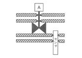
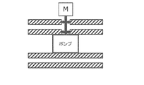
図1及び図2は、プロセスユニット11の実施形態を示す。図1では、プロセスユニットは斜視図で示されており、図2では、プロセスユニットは断面斜視図で示されている。

1.基端側の内側フランジと先端側の内側フランジとの間で延びて危険物質を輸送する内部通路を定義する内壁と、
内部通路で危険物質と関わるように構成されるプロセス制御構造と、
基端側の外側フランジと先端側の外側フランジとの間において内壁の周囲で延びて内壁との間で外部通路を形成する外壁と、
を備える、危険物質のためのプロセスユニット。
第1実施例~第29実施例のいずれか1つに係る第2のプロセスユニットと、
を備え、
第1のプロセスユニットの基端側の内側フランジは、第2のプロセスユニットの先端側の内側フランジとシールされて接触して配置され、第1のプロセスユニットの基端側の外側フランジは、第2のプロセスユニットの先端側の外側フランジとシールされて接触して配置されて、第1のプロセスユニット及び第2のプロセスユニットを通じて連続的な内部通路と、第1のプロセスユニット及び第2のプロセスユニットを通じて連続的な外部通路とを提供する、危険物質を処理するためのプロセスシステム。
Claims (15)
- 少なくとも1つの基端側の内側フランジ(13)と、少なくとも1つの先端側の内側フランジ(14)と、少なくとも1つの基端側の内側フランジ(13)と少なくとも1つの先端側の内側フランジ(14)との間で延びて、危険物質を輸送する内部通路(15)を定義する内壁(12)と、
内部通路で危険物質と関わるように構成されるプロセス制御構造(16)と、
少なくとも1つの基端側の外側フランジ(18)と、少なくとも1つの先端側の外側フランジ(19)と、少なくとも1つの基端側の外側フランジ(18)と少なくとも1つの先端側の外側フランジ(19)との間において内壁周囲で延びて、外部通路(20)を内壁との間で定義する外壁(17)と、
を備え、
外部通路(20)は、中心軸に沿って基端側の外側開口と先端側の外側開口との間で延び、
基端側の外側開口は、基端側の外側フランジ内にあって、
先端側の内側開口は、先端側の外側フランジ内にあって、
内壁(12)は、内壁を通る内部開口(36)を形成して、
外壁(17)は、外壁を通る外部開口(37)を形成して、
内部開口(36)及び外部開口(37)の少なくとも一方は、プロセス制御構造と係合してシールするように配置され、
外部通路は、内部通路の周囲で1つの一体的な空間を形成し、
プロセスユニットは、前記内部開口と前記外部開口とを接続して、前記内壁と前記外壁との間で延びる制御通路をさらに備え、
前記プロセスユニットは、前記制御通路と前記外部通路との間の流体の伝達を生じさせ、それによって、前記制御通路への危険物質のリークの検出を行い、前記外部通路を通じた危険物質の放出を可能にする圧力均一構造を備える、危険物質のためのプロセスユニット(11)。 - 内壁(12)は、内面(31)及び反対側の外面(32)を形成し、
内面は内部通路の表面を形成して、外面は外部通路の表面を形成し、
外壁(17)は、外部通路の表面を形成する内面(33)と、内部通路及び外部通路から離れる方向に向く反対側の外面(34)と、を形成し、
内壁の外面は、外壁の内面に面し、
内壁(12)及び外壁(17)は、外壁の内面と内壁の外面との間で延びる剛性の連結部(35)によって連結され、
剛性の連結部は、外壁に対する内壁の移動を妨げて、外部通路(20)の閉塞空間を占め、換気用の空気の輸送のための自由空間を残す、請求項1に記載のプロセスユニット。 - 内壁の外面の少なくとも50パーセントは、外部通路に露出している、請求項2に記載のプロセスユニット。
- 内部開口(36)及び外部開口(37)は、前記内部通路の中心軸に直交する軸の周囲で同心円状に配置される、請求項1から3のいずれか一項に記載のプロセスユニット。
- プロセス制御構造と係合してシールするように配置された内部開口(36)及び外部開口(37)の少なくとも一方は、対応する壁に設けられる弾力性のあるガスケットを有する、請求項1から4のいずれか一項に記載のプロセスユニット。
- 対応する壁に設けられる弾力性のあるガスケットは、内部開口及び/又は外部開口の周囲の縁の凹部に配置される、請求項5に記載のプロセスユニット。
- 内部開口と外部開口との間で延びて、プロセス制御構造を少なくとも部分的に収容する制御通路(71,73)を備える、請求項1から6のいずれか一項に記載のプロセスユニット。
- 外部通路は、非円形の断面を有する、請求項1から7のいずれか一項に記載のプロセスユニット。
- 基端側の内側フランジ及び基端側の外側フランジは、基端側の連結面を形成して一体的に形成され、
先端側の内側フランジ及び先端側の外側フランジは、先端側の連結面を形成して一体的に形成される、請求項1から8のいずれか一項に記載のプロセスユニット。 - 外部通路は、基端側の連結面の外部通路の複数の開口と、先端側の連結面の外部通路の複数の開口との間で延びる、請求項9に記載のプロセスユニット。
- 先端側の連結面及び基端側の連結面の少なくとも一方は、内壁及び外壁と一体的に形成される、請求項9又は10に記載のプロセスユニット。
- 内壁(12)、外壁(17)、及び剛性の連結部(35)は、一体的に形成される、請求項2から11のいずれか一項に記載のプロセスユニット。
- 内壁(12)、外壁(17)、剛性の連結部(35)、先端側の内側フランジ(14)、先端側の外側フランジ(19)、基端側の内側フランジ(13)、及び基端側の外側フランジ(18)は、一体的に形成される、請求項12に記載のプロセスユニット。
- 請求項1から13のいずれか一項に記載のプロセスユニットを用いて危険物質を輸送する方法であって、
内部通路(15)内で、物質圧力で危険物質の流れを提供するステップと、
外部通路(20)内で、換気圧力で換気用の空気を提供するステップと、
を含み、
換気圧力は、外壁の外部の周囲の圧力よりも低く、
または、換気圧力は、外壁の外部の周囲の圧力よりも高く、
換気用の空気は外部通路で流れが無いように提供され、換気圧力は静圧である、方法。 - 請求項1から13のいずれか一項に記載のプロセスユニットを用いて危険物質を輸送する方法であって、
内部通路(15)内で、物質圧力で危険物質の流れを提供するステップと、
外部通路(20)内で、換気圧力で換気用の空気を提供するステップと、
を含み、
換気圧力は、外壁の外部の周囲の圧力よりも低く、
または、換気圧力は、外壁の外部の周囲の圧力よりも高く、
換気用の空気は外部通路で流れがあるように提供され、換気圧力は動圧である、方法。
Applications Claiming Priority (5)
| Application Number | Priority Date | Filing Date | Title |
|---|---|---|---|
| EP17152696.5 | 2017-01-23 | ||
| EP17152696 | 2017-01-23 | ||
| EP17158935.1 | 2017-03-02 | ||
| EP17158935 | 2017-03-02 | ||
| PCT/EP2018/051581 WO2018134437A1 (en) | 2017-01-23 | 2018-01-23 | A process unit for hazardous material |
Publications (3)
| Publication Number | Publication Date |
|---|---|
| JP2020507035A JP2020507035A (ja) | 2020-03-05 |
| JP2020507035A5 JP2020507035A5 (ja) | 2021-02-18 |
| JP7069217B2 true JP7069217B2 (ja) | 2022-05-17 |
Family
ID=60997500
Family Applications (1)
| Application Number | Title | Priority Date | Filing Date |
|---|---|---|---|
| JP2019560477A Active JP7069217B2 (ja) | 2017-01-23 | 2018-01-23 | 危険物質のためのプロセスユニット |
Country Status (6)
| Country | Link |
|---|---|
| EP (1) | EP3571386B1 (ja) |
| JP (1) | JP7069217B2 (ja) |
| KR (1) | KR102492784B1 (ja) |
| CN (1) | CN110312859B (ja) |
| DK (1) | DK3571386T3 (ja) |
| WO (1) | WO2018134437A1 (ja) |
Families Citing this family (2)
| Publication number | Priority date | Publication date | Assignee | Title |
|---|---|---|---|---|
| WO2020169191A1 (en) * | 2019-02-20 | 2020-08-27 | Wärtsilä Finland Oy | A gaseous fuel feeding system |
| EP3786498A1 (de) * | 2019-08-26 | 2021-03-03 | Winterthur Gas & Diesel AG | Absperrventil für eine doppelwandige leitung, gaszuführsystem und grossmotor |
Citations (1)
| Publication number | Priority date | Publication date | Assignee | Title |
|---|---|---|---|---|
| US20060278760A1 (en) | 2005-06-09 | 2006-12-14 | The Boeing Company | Fittings with redundant seals for aircraft fuel lines, fuel tanks, and other systems |
Family Cites Families (27)
| Publication number | Priority date | Publication date | Assignee | Title |
|---|---|---|---|---|
| GB675151A (en) * | 1950-05-30 | 1952-07-02 | Chiksan Co | Swivel pipe joints for calender rolls, or the like |
| DE2723679A1 (de) * | 1976-05-27 | 1977-12-15 | Tokan Kogyo Co Ltd | Verbindungsstueck fuer mehrwandige thermoplastische rohrleitungen und verfahren zu seiner herstellung |
| JPS5325916U (ja) * | 1976-08-12 | 1978-03-04 | ||
| GB2017818A (en) * | 1978-04-03 | 1979-10-10 | Bendix Corp | Throttle assembly for an internal combustion engine |
| JP2544332Y2 (ja) * | 1990-11-09 | 1997-08-20 | 臼井国際産業株式会社 | フユーエルデリバリパイプ |
| US5806551A (en) * | 1993-11-19 | 1998-09-15 | Novoste Corporation | Automatic fluid control valve |
| JP3065884B2 (ja) * | 1994-04-18 | 2000-07-17 | 三菱樹脂株式会社 | 掃除口付き二層管継手 |
| JP3261105B2 (ja) * | 1998-11-04 | 2002-02-25 | 住友重機械工業株式会社 | 複数受給口を有する機器への選択接続用配管ユニット |
| US6475255B1 (en) * | 2000-11-07 | 2002-11-05 | Robert A. Walker, Jr. | Serviceable air filter/oil separator assembly |
| US20070181204A1 (en) * | 2006-02-06 | 2007-08-09 | Stout William K | Insulated dual wall duct |
| CN201209733Y (zh) * | 2008-06-19 | 2009-03-18 | 杭州沈氏换热器有限公司 | 一种双层管道连接装置 |
| US8956556B2 (en) * | 2008-07-02 | 2015-02-17 | Eaton Corporation | Dielectric isolators |
| JP5800836B2 (ja) * | 2010-02-25 | 2015-10-28 | アイデックス・ヘルス・アンド・サイエンス・リミテッド ライアビリティ カンパニーIdex Health & Science Llc | マイクロ流体弁取り付け装置、マイクロ流体弁アセンブリ、及び、マイクロ流体弁システム |
| US20130220270A1 (en) * | 2010-05-24 | 2013-08-29 | Village Road Co., Ltd. | Retrofit gas fuel supply kit retrofittable to internal combustion engine using liquid fuel |
| US20120048000A1 (en) * | 2010-08-31 | 2012-03-01 | Joseph Kirzhner | Method and system to detect and measure piping fuel leak |
| GB2493545B (en) * | 2011-08-11 | 2013-09-11 | Technip France | T-piece preformer |
| EP2589788B1 (en) * | 2011-11-04 | 2016-10-12 | Caterpillar Motoren GmbH & Co. KG | Cylinder head |
| CN102493899A (zh) * | 2011-12-05 | 2012-06-13 | 北京理工大学 | 导流套管式螺旋混合进气装置 |
| DE102012009266B4 (de) * | 2012-05-11 | 2016-12-29 | L'Air Liquide, Société Anonyme pour l'Etude et l'Exploitation des Procédés Georges Claude | Gasabzug für einen Vergasungsreaktor |
| HK1168240A2 (en) * | 2012-08-24 | 2012-12-21 | Active Tools Int Hk Ltd | A valve with at least two active positions |
| CN103047487A (zh) * | 2013-01-21 | 2013-04-17 | 刘建华 | 双孔同心热力管 |
| CN103452651A (zh) * | 2013-09-16 | 2013-12-18 | 淄博淄柴新能源有限公司 | 内混式大缸径高氢燃气发动机 |
| CN103821638B (zh) * | 2014-03-21 | 2016-04-06 | 潍坊威度电子科技有限公司 | 气体发动机燃料供给与空气进气嵌入式总成 |
| CN103939240B (zh) * | 2014-03-25 | 2016-08-17 | 南车玉柴四川发动机股份有限公司 | 多点进气双燃料发动机的双层燃气输送系统 |
| US9605633B2 (en) * | 2014-04-30 | 2017-03-28 | Electro-Motive Diesel, Inc. | Manifold assembly for dual-walled pipe |
| CN106688066A (zh) * | 2014-08-26 | 2017-05-17 | 株式会社村田制作所 | 具有钙钛矿电介质的卷起电容器及生产其的工艺 |
| DE102016204764B4 (de) * | 2016-03-22 | 2020-04-23 | Mtu Friedrichshafen Gmbh | Messeinrichtung, Brenngasversorgungseinrichtung mit einer solchen Messeinrichtung und Brennkraftmaschine mit einer solchen Brenngasversorgungseinrichtung |
-
2018
- 2018-01-23 KR KR1020197023243A patent/KR102492784B1/ko active IP Right Grant
- 2018-01-23 WO PCT/EP2018/051581 patent/WO2018134437A1/en active Search and Examination
- 2018-01-23 DK DK18700619.2T patent/DK3571386T3/da active
- 2018-01-23 JP JP2019560477A patent/JP7069217B2/ja active Active
- 2018-01-23 CN CN201880007988.0A patent/CN110312859B/zh active Active
- 2018-01-23 EP EP18700619.2A patent/EP3571386B1/en active Active
Patent Citations (1)
| Publication number | Priority date | Publication date | Assignee | Title |
|---|---|---|---|---|
| US20060278760A1 (en) | 2005-06-09 | 2006-12-14 | The Boeing Company | Fittings with redundant seals for aircraft fuel lines, fuel tanks, and other systems |
Also Published As
| Publication number | Publication date |
|---|---|
| DK3571386T3 (da) | 2021-06-14 |
| KR102492784B1 (ko) | 2023-01-27 |
| CN110312859B (zh) | 2021-09-17 |
| WO2018134437A1 (en) | 2018-07-26 |
| EP3571386A1 (en) | 2019-11-27 |
| KR20190105612A (ko) | 2019-09-17 |
| CN110312859A (zh) | 2019-10-08 |
| EP3571386B1 (en) | 2021-03-10 |
| JP2020507035A (ja) | 2020-03-05 |
Similar Documents
| Publication | Publication Date | Title |
|---|---|---|
| US8701467B2 (en) | Flange fitting with leak sensor port | |
| US9605633B2 (en) | Manifold assembly for dual-walled pipe | |
| US5312137A (en) | Safety shield | |
| JP7069217B2 (ja) | 危険物質のためのプロセスユニット | |
| US8998213B2 (en) | Mechanical seal device and processing apparatus | |
| US20190226592A1 (en) | Double block and bleed valve with flex bypass for effective and efficient system isolation | |
| US20110215565A1 (en) | Coupling element for connecting two pipe ends | |
| CN110735739B (zh) | 带有设置在引导流体的构件中的文丘里喷嘴的内燃机 | |
| US6178989B1 (en) | Safety element for a duct | |
| US9303598B2 (en) | Device for aeration and ventilation of a fuel system | |
| CN109210300B (zh) | 转换接头 | |
| US2834465A (en) | Swivel hose assembly | |
| CN112219024B (zh) | 一种气体供应系统 | |
| FI101173B (fi) | Kaksoissulku- ja purkuventtiilijärjestelmä | |
| CN112219023B (zh) | 一种气阀单元 | |
| KR101818075B1 (ko) | 입형다단펌프의 더블 실링 구조 | |
| AU644613B2 (en) | Emission control device | |
| JP2005069157A (ja) | 内燃機関用エアポンプ | |
| US9383051B1 (en) | Shrouded dynamically sealed rotary coupling | |
| BR112020025351B1 (pt) | Junta tubular e instalação | |
| US6176248B1 (en) | Submerged hydraulic value actuator with leak protection | |
| KR20230011360A (ko) | 가스 밸브 유닛 | |
| EP1790897A1 (en) | Connecting system for pneumatic circuits to facilitate leak detection | |
| JPH11230377A (ja) | 弁構造 | |
| JPH0151766B2 (ja) |
Legal Events
| Date | Code | Title | Description |
|---|---|---|---|
| A521 | Request for written amendment filed |
Free format text: JAPANESE INTERMEDIATE CODE: A523 Effective date: 20210106 |
|
| A621 | Written request for application examination |
Free format text: JAPANESE INTERMEDIATE CODE: A621 Effective date: 20210106 |
|
| A977 | Report on retrieval |
Free format text: JAPANESE INTERMEDIATE CODE: A971007 Effective date: 20211117 |
|
| A131 | Notification of reasons for refusal |
Free format text: JAPANESE INTERMEDIATE CODE: A131 Effective date: 20211124 |
|
| A521 | Request for written amendment filed |
Free format text: JAPANESE INTERMEDIATE CODE: A523 Effective date: 20220120 |
|
| TRDD | Decision of grant or rejection written | ||
| A01 | Written decision to grant a patent or to grant a registration (utility model) |
Free format text: JAPANESE INTERMEDIATE CODE: A01 Effective date: 20220405 |
|
| A61 | First payment of annual fees (during grant procedure) |
Free format text: JAPANESE INTERMEDIATE CODE: A61 Effective date: 20220502 |
|
| R150 | Certificate of patent or registration of utility model |
Ref document number: 7069217 Country of ref document: JP Free format text: JAPANESE INTERMEDIATE CODE: R150 |