JP7003073B2 - Magnetic tapes, magnetic tape cartridges and magnetic tape devices - Google Patents
Magnetic tapes, magnetic tape cartridges and magnetic tape devices Download PDFInfo
- Publication number
- JP7003073B2 JP7003073B2 JP2019016520A JP2019016520A JP7003073B2 JP 7003073 B2 JP7003073 B2 JP 7003073B2 JP 2019016520 A JP2019016520 A JP 2019016520A JP 2019016520 A JP2019016520 A JP 2019016520A JP 7003073 B2 JP7003073 B2 JP 7003073B2
- Authority
- JP
- Japan
- Prior art keywords
- magnetic
- magnetic tape
- reading
- track
- magnetic layer
- Prior art date
- Legal status (The legal status is an assumption and is not a legal conclusion. Google has not performed a legal analysis and makes no representation as to the accuracy of the status listed.)
- Active
Links
Images


Classifications
-
- G—PHYSICS
- G11—INFORMATION STORAGE
- G11B—INFORMATION STORAGE BASED ON RELATIVE MOVEMENT BETWEEN RECORD CARRIER AND TRANSDUCER
- G11B5/00—Recording by magnetisation or demagnetisation of a record carrier; Reproducing by magnetic means; Record carriers therefor
- G11B5/127—Structure or manufacture of heads, e.g. inductive
- G11B5/33—Structure or manufacture of flux-sensitive heads, i.e. for reproduction only; Combination of such heads with means for recording or erasing only
- G11B5/39—Structure or manufacture of flux-sensitive heads, i.e. for reproduction only; Combination of such heads with means for recording or erasing only using magneto-resistive devices or effects
- G11B5/3903—Structure or manufacture of flux-sensitive heads, i.e. for reproduction only; Combination of such heads with means for recording or erasing only using magneto-resistive devices or effects using magnetic thin film layers or their effects, the films being part of integrated structures
- G11B5/3906—Details related to the use of magnetic thin film layers or to their effects
- G11B5/3945—Heads comprising more than one sensitive element
- G11B5/3948—Heads comprising more than one sensitive element the sensitive elements being active read-out elements
- G11B5/3958—Heads comprising more than one sensitive element the sensitive elements being active read-out elements the active elements being arranged in a single plane, e.g. "matrix" disposition
-
- G—PHYSICS
- G11—INFORMATION STORAGE
- G11B—INFORMATION STORAGE BASED ON RELATIVE MOVEMENT BETWEEN RECORD CARRIER AND TRANSDUCER
- G11B20/00—Signal processing not specific to the method of recording or reproducing; Circuits therefor
- G11B20/10—Digital recording or reproducing
- G11B20/10009—Improvement or modification of read or write signals
- G11B20/10046—Improvement or modification of read or write signals filtering or equalising, e.g. setting the tap weights of an FIR filter
-
- G—PHYSICS
- G11—INFORMATION STORAGE
- G11B—INFORMATION STORAGE BASED ON RELATIVE MOVEMENT BETWEEN RECORD CARRIER AND TRANSDUCER
- G11B27/00—Editing; Indexing; Addressing; Timing or synchronising; Monitoring; Measuring tape travel
- G11B27/02—Editing, e.g. varying the order of information signals recorded on, or reproduced from, record carriers
- G11B27/022—Electronic editing of analogue information signals, e.g. audio or video signals
-
- G—PHYSICS
- G11—INFORMATION STORAGE
- G11B—INFORMATION STORAGE BASED ON RELATIVE MOVEMENT BETWEEN RECORD CARRIER AND TRANSDUCER
- G11B5/00—Recording by magnetisation or demagnetisation of a record carrier; Reproducing by magnetic means; Record carriers therefor
- G11B5/48—Disposition or mounting of heads or head supports relative to record carriers ; arrangements of heads, e.g. for scanning the record carrier to increase the relative speed
- G11B5/58—Disposition or mounting of heads or head supports relative to record carriers ; arrangements of heads, e.g. for scanning the record carrier to increase the relative speed with provision for moving the head for the purpose of maintaining alignment of the head relative to the record carrier during transducing operation, e.g. to compensate for surface irregularities of the latter or for track following
- G11B5/584—Disposition or mounting of heads or head supports relative to record carriers ; arrangements of heads, e.g. for scanning the record carrier to increase the relative speed with provision for moving the head for the purpose of maintaining alignment of the head relative to the record carrier during transducing operation, e.g. to compensate for surface irregularities of the latter or for track following for track following on tapes
-
- G—PHYSICS
- G11—INFORMATION STORAGE
- G11B—INFORMATION STORAGE BASED ON RELATIVE MOVEMENT BETWEEN RECORD CARRIER AND TRANSDUCER
- G11B5/00—Recording by magnetisation or demagnetisation of a record carrier; Reproducing by magnetic means; Record carriers therefor
- G11B5/62—Record carriers characterised by the selection of the material
- G11B5/68—Record carriers characterised by the selection of the material comprising one or more layers of magnetisable material homogeneously mixed with a bonding agent
- G11B5/70—Record carriers characterised by the selection of the material comprising one or more layers of magnetisable material homogeneously mixed with a bonding agent on a base layer
- G11B5/7013—Record carriers characterised by the selection of the material comprising one or more layers of magnetisable material homogeneously mixed with a bonding agent on a base layer characterised by the dispersing agent
-
- G—PHYSICS
- G11—INFORMATION STORAGE
- G11B—INFORMATION STORAGE BASED ON RELATIVE MOVEMENT BETWEEN RECORD CARRIER AND TRANSDUCER
- G11B5/00—Recording by magnetisation or demagnetisation of a record carrier; Reproducing by magnetic means; Record carriers therefor
- G11B5/62—Record carriers characterised by the selection of the material
- G11B5/68—Record carriers characterised by the selection of the material comprising one or more layers of magnetisable material homogeneously mixed with a bonding agent
- G11B5/70—Record carriers characterised by the selection of the material comprising one or more layers of magnetisable material homogeneously mixed with a bonding agent on a base layer
- G11B5/702—Record carriers characterised by the selection of the material comprising one or more layers of magnetisable material homogeneously mixed with a bonding agent on a base layer characterised by the bonding agent
- G11B5/7021—Record carriers characterised by the selection of the material comprising one or more layers of magnetisable material homogeneously mixed with a bonding agent on a base layer characterised by the bonding agent containing a polyurethane or a polyisocyanate
- G11B5/7022—Record carriers characterised by the selection of the material comprising one or more layers of magnetisable material homogeneously mixed with a bonding agent on a base layer characterised by the bonding agent containing a polyurethane or a polyisocyanate containing mixtures of polyurethanes or polyisocyanates with other polymers
-
- G—PHYSICS
- G11—INFORMATION STORAGE
- G11B—INFORMATION STORAGE BASED ON RELATIVE MOVEMENT BETWEEN RECORD CARRIER AND TRANSDUCER
- G11B5/00—Recording by magnetisation or demagnetisation of a record carrier; Reproducing by magnetic means; Record carriers therefor
- G11B5/62—Record carriers characterised by the selection of the material
- G11B5/68—Record carriers characterised by the selection of the material comprising one or more layers of magnetisable material homogeneously mixed with a bonding agent
- G11B5/70—Record carriers characterised by the selection of the material comprising one or more layers of magnetisable material homogeneously mixed with a bonding agent on a base layer
- G11B5/706—Record carriers characterised by the selection of the material comprising one or more layers of magnetisable material homogeneously mixed with a bonding agent on a base layer characterised by the composition of the magnetic material
- G11B5/70605—Record carriers characterised by the selection of the material comprising one or more layers of magnetisable material homogeneously mixed with a bonding agent on a base layer characterised by the composition of the magnetic material metals or alloys
- G11B5/7061—Record carriers characterised by the selection of the material comprising one or more layers of magnetisable material homogeneously mixed with a bonding agent on a base layer characterised by the composition of the magnetic material metals or alloys with a non-magnetic core
-
- G—PHYSICS
- G11—INFORMATION STORAGE
- G11B—INFORMATION STORAGE BASED ON RELATIVE MOVEMENT BETWEEN RECORD CARRIER AND TRANSDUCER
- G11B5/00—Recording by magnetisation or demagnetisation of a record carrier; Reproducing by magnetic means; Record carriers therefor
- G11B5/62—Record carriers characterised by the selection of the material
- G11B5/68—Record carriers characterised by the selection of the material comprising one or more layers of magnetisable material homogeneously mixed with a bonding agent
- G11B5/70—Record carriers characterised by the selection of the material comprising one or more layers of magnetisable material homogeneously mixed with a bonding agent on a base layer
- G11B5/706—Record carriers characterised by the selection of the material comprising one or more layers of magnetisable material homogeneously mixed with a bonding agent on a base layer characterised by the composition of the magnetic material
- G11B5/70626—Record carriers characterised by the selection of the material comprising one or more layers of magnetisable material homogeneously mixed with a bonding agent on a base layer characterised by the composition of the magnetic material containing non-metallic substances
- G11B5/70642—Record carriers characterised by the selection of the material comprising one or more layers of magnetisable material homogeneously mixed with a bonding agent on a base layer characterised by the composition of the magnetic material containing non-metallic substances iron oxides
- G11B5/70678—Ferrites
- G11B5/70684—Ferro-ferrioxydes
-
- G—PHYSICS
- G11—INFORMATION STORAGE
- G11B—INFORMATION STORAGE BASED ON RELATIVE MOVEMENT BETWEEN RECORD CARRIER AND TRANSDUCER
- G11B5/00—Recording by magnetisation or demagnetisation of a record carrier; Reproducing by magnetic means; Record carriers therefor
- G11B5/62—Record carriers characterised by the selection of the material
- G11B5/68—Record carriers characterised by the selection of the material comprising one or more layers of magnetisable material homogeneously mixed with a bonding agent
- G11B5/70—Record carriers characterised by the selection of the material comprising one or more layers of magnetisable material homogeneously mixed with a bonding agent on a base layer
- G11B5/708—Record carriers characterised by the selection of the material comprising one or more layers of magnetisable material homogeneously mixed with a bonding agent on a base layer characterised by addition of non-magnetic particles to the layer
-
- G—PHYSICS
- G11—INFORMATION STORAGE
- G11B—INFORMATION STORAGE BASED ON RELATIVE MOVEMENT BETWEEN RECORD CARRIER AND TRANSDUCER
- G11B5/00—Recording by magnetisation or demagnetisation of a record carrier; Reproducing by magnetic means; Record carriers therefor
- G11B5/62—Record carriers characterised by the selection of the material
- G11B5/73—Base layers, i.e. all non-magnetic layers lying under a lowermost magnetic recording layer, e.g. including any non-magnetic layer in between a first magnetic recording layer and either an underlying substrate or a soft magnetic underlayer
- G11B5/733—Base layers, i.e. all non-magnetic layers lying under a lowermost magnetic recording layer, e.g. including any non-magnetic layer in between a first magnetic recording layer and either an underlying substrate or a soft magnetic underlayer characterised by the addition of non-magnetic particles
-
- G—PHYSICS
- G11—INFORMATION STORAGE
- G11B—INFORMATION STORAGE BASED ON RELATIVE MOVEMENT BETWEEN RECORD CARRIER AND TRANSDUCER
- G11B5/00—Recording by magnetisation or demagnetisation of a record carrier; Reproducing by magnetic means; Record carriers therefor
- G11B5/62—Record carriers characterised by the selection of the material
- G11B5/73—Base layers, i.e. all non-magnetic layers lying under a lowermost magnetic recording layer, e.g. including any non-magnetic layer in between a first magnetic recording layer and either an underlying substrate or a soft magnetic underlayer
- G11B5/735—Base layers, i.e. all non-magnetic layers lying under a lowermost magnetic recording layer, e.g. including any non-magnetic layer in between a first magnetic recording layer and either an underlying substrate or a soft magnetic underlayer characterised by the back layer
- G11B5/7356—Base layers, i.e. all non-magnetic layers lying under a lowermost magnetic recording layer, e.g. including any non-magnetic layer in between a first magnetic recording layer and either an underlying substrate or a soft magnetic underlayer characterised by the back layer comprising non-magnetic particles in the back layer, e.g. particles of TiO2, ZnO or SiO2
-
- G—PHYSICS
- G11—INFORMATION STORAGE
- G11B—INFORMATION STORAGE BASED ON RELATIVE MOVEMENT BETWEEN RECORD CARRIER AND TRANSDUCER
- G11B5/00—Recording by magnetisation or demagnetisation of a record carrier; Reproducing by magnetic means; Record carriers therefor
- G11B5/74—Record carriers characterised by the form, e.g. sheet shaped to wrap around a drum
- G11B5/78—Tape carriers
-
- H—ELECTRICITY
- H01—ELECTRIC ELEMENTS
- H01F—MAGNETS; INDUCTANCES; TRANSFORMERS; SELECTION OF MATERIALS FOR THEIR MAGNETIC PROPERTIES
- H01F1/00—Magnets or magnetic bodies characterised by the magnetic materials therefor; Selection of materials for their magnetic properties
- H01F1/01—Magnets or magnetic bodies characterised by the magnetic materials therefor; Selection of materials for their magnetic properties of inorganic materials
- H01F1/03—Magnets or magnetic bodies characterised by the magnetic materials therefor; Selection of materials for their magnetic properties of inorganic materials characterised by their coercivity
- H01F1/032—Magnets or magnetic bodies characterised by the magnetic materials therefor; Selection of materials for their magnetic properties of inorganic materials characterised by their coercivity of hard-magnetic materials
- H01F1/10—Magnets or magnetic bodies characterised by the magnetic materials therefor; Selection of materials for their magnetic properties of inorganic materials characterised by their coercivity of hard-magnetic materials non-metallic substances, e.g. ferrites, e.g. [(Ba,Sr)O(Fe2O3)6] ferrites with hexagonal structure
- H01F1/11—Magnets or magnetic bodies characterised by the magnetic materials therefor; Selection of materials for their magnetic properties of inorganic materials characterised by their coercivity of hard-magnetic materials non-metallic substances, e.g. ferrites, e.g. [(Ba,Sr)O(Fe2O3)6] ferrites with hexagonal structure in the form of particles
- H01F1/113—Magnets or magnetic bodies characterised by the magnetic materials therefor; Selection of materials for their magnetic properties of inorganic materials characterised by their coercivity of hard-magnetic materials non-metallic substances, e.g. ferrites, e.g. [(Ba,Sr)O(Fe2O3)6] ferrites with hexagonal structure in the form of particles in a bonding agent
-
- B—PERFORMING OPERATIONS; TRANSPORTING
- B82—NANOTECHNOLOGY
- B82Y—SPECIFIC USES OR APPLICATIONS OF NANOSTRUCTURES; MEASUREMENT OR ANALYSIS OF NANOSTRUCTURES; MANUFACTURE OR TREATMENT OF NANOSTRUCTURES
- B82Y10/00—Nanotechnology for information processing, storage or transmission, e.g. quantum computing or single electron logic
-
- B—PERFORMING OPERATIONS; TRANSPORTING
- B82—NANOTECHNOLOGY
- B82Y—SPECIFIC USES OR APPLICATIONS OF NANOSTRUCTURES; MEASUREMENT OR ANALYSIS OF NANOSTRUCTURES; MANUFACTURE OR TREATMENT OF NANOSTRUCTURES
- B82Y25/00—Nanomagnetism, e.g. magnetoimpedance, anisotropic magnetoresistance, giant magnetoresistance or tunneling magnetoresistance
-
- G—PHYSICS
- G11—INFORMATION STORAGE
- G11B—INFORMATION STORAGE BASED ON RELATIVE MOVEMENT BETWEEN RECORD CARRIER AND TRANSDUCER
- G11B5/00—Recording by magnetisation or demagnetisation of a record carrier; Reproducing by magnetic means; Record carriers therefor
- G11B2005/0002—Special dispositions or recording techniques
- G11B2005/0005—Arrangements, methods or circuits
- G11B2005/001—Controlling recording characteristics of record carriers or transducing characteristics of transducers by means not being part of their structure
- G11B2005/0013—Controlling recording characteristics of record carriers or transducing characteristics of transducers by means not being part of their structure of transducers, e.g. linearisation, equalisation
Description
本発明は、磁気テープ、磁気テープカートリッジおよび磁気テープ装置に関する。 The present invention relates to magnetic tapes, magnetic tape cartridges and magnetic tape devices.
磁気記録媒体へのデータの記録および/または記録されたデータの読み取り(再生)を行う磁気記録再生装置は、磁気ディスク装置と磁気テープ装置に大別される。磁気ディスク装置の代表例はHDD(Hard Disk Drive)である。磁気ディスク装置では、磁気記録媒体として磁気ディスクが使用される。一方、磁気テープ装置では、磁気記録媒体として磁気テープが使用される。 A magnetic recording / reproducing device that records data on a magnetic recording medium and / or reads (reproduces) the recorded data is roughly classified into a magnetic disk device and a magnetic tape device. A typical example of a magnetic disk device is an HDD (Hard Disk Drive). In a magnetic disk device, a magnetic disk is used as a magnetic recording medium. On the other hand, in a magnetic tape device, a magnetic tape is used as a magnetic recording medium.
磁気ディスク装置および磁気テープ装置のいずれにおいても、記録トラック幅を狭小化することは記録容量を高めるため(高容量化)に好ましい。他方、記録トラック幅を狭小化するほど、再生時に読取対象トラックの信号に隣接トラックの信号が混入し易くなるため、SNR(Signal-to-Noise Ratio)等の再生品質を維持することは困難になる。この点に関し、近年、複数の読取素子(「再生素子」とも呼ばれる。)によって記録トラックの信号を二次元的に読み取ることにより、再生品質の向上を図ることが提案されている(例えば特許文献1~3参照)。こうして再生品質を向上できれば、記録トラック幅を狭小化しても再生品質を維持することができるため、記録トラック幅の狭小化により記録容量を高めることが可能となる。 In both the magnetic disk device and the magnetic tape device, narrowing the recording track width is preferable for increasing the recording capacity (increasing the capacity). On the other hand, as the recording track width is narrowed, it becomes easier for the signal of the adjacent track to be mixed with the signal of the track to be read during reproduction, so that it becomes difficult to maintain the reproduction quality such as SNR (Signal-to-Noise Ratio). Become. In this regard, in recent years, it has been proposed to improve the reproduction quality by two-dimensionally reading the signal of the recording track by a plurality of reading elements (also referred to as “reproduction elements”) (for example, Patent Document 1). See ~ 3). If the reproduction quality can be improved in this way, the reproduction quality can be maintained even if the recording track width is narrowed, so that the recording capacity can be increased by narrowing the recording track width.
特許文献1および2では、磁気ディスク装置に関する検討が行われている。一方、磁気テープは、近年、大容量のデータを長期間保存するためのデータストレージメディアとして注目されている。しかし、磁気テープ装置は、一般に、磁気テープと読取素子とが接触し摺動することによってデータ読取(再生)が行われる摺動型の装置である。そのため、再生時に読取素子と読取対象トラックとの相対位置が変動し易く、再生品質の向上は、磁気ディスク装置と比べてより困難な傾向がある。特許文献3には、磁気テープ装置(テープドライブ)に関する記載はあるものの、磁気テープ装置における再生品質向上のための具体的な手段は示されていない。
本発明の一態様は、複数の読取素子(再生素子)を利用する磁気テープ装置において、良好な再生品質でのデータの再生が可能な磁気テープを提供することを目的とする。 One aspect of the present invention is to provide a magnetic tape capable of reproducing data with good reproduction quality in a magnetic tape device using a plurality of reading elements (reproduction elements).
本発明の一態様は、
非磁性支持体と、強磁性粉末および結合剤を含む磁性層と、を有する磁気テープであって、
上記磁性層は、タイミングベースサーボパターンを有し、
上記タイミングベースサーボパターンの磁気力顕微鏡観察により特定されるエッジ形状は、磁気テープの長手方向における理想形状からの位置ずれ幅の累積分布関数99.9%の値L99.9と上記累積分布関数0.1%の値L0.1との差分(L99.9-L0.1)が180nm以下である形状であり、かつ
上記磁性層の面内方向について測定される屈折率Nxyと上記磁性層の厚み方向について測定される屈折率Nzとの差分の絶対値ΔN(以下、「(磁性層の)ΔN」とも記載する。)が0.25以上0.40以下である、磁気テープ、
に関する。
One aspect of the present invention is
A magnetic tape having a non-magnetic support and a magnetic layer containing a ferromagnetic powder and a binder.
The magnetic layer has a timing-based servo pattern and has a timing-based servo pattern.
The edge shape specified by the magnetic force microscope observation of the timing-based servo pattern has a cumulative distribution function of 99.9% of the positional deviation width from the ideal shape in the longitudinal direction of the magnetic tape, L 99.9 , and the cumulative distribution function. The shape has a shape in which the difference (L 99.9 -L 0.1 ) from the 0.1% value L 0.1 is 180 nm or less, and the refractive index Nxy measured in the in-plane direction of the magnetic layer and the above. A magnetic tape, wherein the absolute value ΔN (hereinafter, also referred to as “ΔN (of the magnetic layer)”) of the difference from the refractive index Nz measured in the thickness direction of the magnetic layer is 0.25 or more and 0.40 or less.
Regarding.
一態様では、Nxy>Nzであることができ、上記屈折率Nxyと上記屈折率Nzとの差分(Nxy-Nz)が0.25以上0.40以下であることができる。 In one aspect, Nxy> Nz can be satisfied, and the difference (Nxy—Nz) between the refractive index Nxy and the refractive index Nz can be 0.25 or more and 0.40 or less.
一態様では、上記タイミングベースサーボパターンは、磁気テープの幅方向の一方から他方に向かって連続的に延び、かつ上記幅方向に対して角度αで傾斜した直線状サーボパターンであることができ、上記理想形状は、上記角度αの方向に延びる直線形状であることができる。 In one aspect, the timing-based servo pattern can be a linear servo pattern that extends continuously from one side in the width direction of the magnetic tape toward the other and is inclined at an angle α with respect to the width direction. The ideal shape can be a linear shape extending in the direction of the angle α.
一態様では、上記差分(L99.9-L0.1)は、100nm以上180nm以下であることができる。 In one aspect, the difference (L 99.9 -L 0.1 ) can be 100 nm or more and 180 nm or less.
一態様では、上記磁気テープは、上記非磁性支持体と上記磁性層との間に、非磁性粉末および結合剤を含む非磁性層を有することができる。 In one aspect, the magnetic tape can have a non-magnetic layer containing a non-magnetic powder and a binder between the non-magnetic support and the magnetic layer.
一態様では、上記磁気テープは、上記非磁性支持体の上記磁性層を有する表面側とは反対の表面側に、非磁性粉末および結合剤を含むバックコート層を有することができる。 In one aspect, the magnetic tape can have a backcoat layer containing a non-magnetic powder and a binder on the surface side of the non-magnetic support opposite to the surface side having the magnetic layer.
本発明の一態様は、上記磁気テープを含む磁気テープカートリッジに関する。 One aspect of the present invention relates to a magnetic tape cartridge containing the magnetic tape.
本発明の一態様は、
磁気テープと、
読取素子ユニットと、
抽出部と、
を含み、
上記磁気テープは、上記の本発明の一態様にかかる磁気テープであり、
上記読取素子ユニットは、
上記磁気テープに含まれるトラック領域のうちの読取対象トラックを含む特定トラック領域からデータを各々読み取る複数の読取素子を有し、
上記抽出部は、上記読取素子毎の読取結果の各々に対して波形等化処理を施すことにより、上記読取結果から、上記読取対象トラックに由来するデータを抽出する、磁気テープ装置、
に関する。
One aspect of the present invention is
With magnetic tape,
With the reading element unit
Extractor and
Including
The magnetic tape is a magnetic tape according to one aspect of the present invention.
The reading element unit is
It has a plurality of reading elements for reading data from a specific track area including a track to be read among the track areas included in the magnetic tape.
The extraction unit is a magnetic tape device that extracts data derived from the read target track from the read results by performing waveform equalization processing on each of the read results for each reading element.
Regarding.
一態様では、上記複数の読取素子は、磁気テープに含まれるトラック領域のうちの読取対象トラックを含む特定トラック領域からデータをリニアスキャン方式で各々読み取ることができる。 In one aspect, the plurality of reading elements can each read data from a specific track area including a read target track in the track area included in the magnetic tape by a linear scan method.
一態様では、上記波形等化処理は、上記磁気テープと上記読取素子ユニットとの位置のずれ量に応じた波形等化処理であることができる。 In one aspect, the waveform equalization process can be a waveform equalization process according to the amount of displacement between the magnetic tape and the reading element unit.
一態様では、上記波形等化処理は、上記ずれ量に応じて定められるタップ係数を用いて行われ得る。 In one aspect, the waveform equalization process can be performed using a tap coefficient determined according to the deviation amount.
一態様では、上記ずれ量は、上記磁気テープの磁性層のタイミングベースサーボパターンを上記サーボ素子が読み取ることにより得られた結果に応じて定められ得る。 In one aspect, the deviation amount can be determined according to the result obtained by reading the timing-based servo pattern of the magnetic layer of the magnetic tape by the servo element.
一態様では、上記読取素子ユニットはサーボ素子を含むことができ、上記サーボ素子により行われる読取動作に同期して、上記読取素子ユニットの読取動作が行われ得る。 In one aspect, the reading element unit may include a servo element, and the reading operation of the reading element unit may be performed in synchronization with the reading operation performed by the servo element.
一態様では、上記複数の読取素子の互いの一部は、上記磁気テープの走行方向で重なっていることができる。 In one aspect, the plurality of reading elements may overlap each other in the traveling direction of the magnetic tape.
一態様では、上記特定トラック領域は、上記読取対象トラックと上記読取対象トラックに隣接している隣接トラックとを含む領域であることができ、上記複数の読取素子の各々は、上記磁気テープとの位置関係が変化した場合に、上記読取対象トラックおよび上記隣接トラックの双方に対して、共に跨っていることができる。 In one aspect, the specific track region can be a region including the read target track and an adjacent track adjacent to the read target track, and each of the plurality of reading elements has the magnetic tape. When the positional relationship changes, both the read target track and the adjacent track can be straddled.
一態様では、上記複数の読取素子は、上記磁気テープの幅方向に、近接した状態で並べて配置されていることができる。 In one aspect, the plurality of reading elements can be arranged side by side in close proximity to each other in the width direction of the magnetic tape.
一態様では、上記磁気テープの幅方向において、上記複数の読取素子は、上記読取対象トラック内に収まっていることができる。 In one aspect, the plurality of reading elements can be accommodated in the reading target track in the width direction of the magnetic tape.
一態様では、上記複数の読取素子の各々について、上記読取対象トラックとの重複領域と上記読取対象トラックに隣接している隣接トラックとの重複領域との比が上記ずれ量から特定され得て、特定された上記比に応じて上記タップ係数が定められ得る。 In one aspect, for each of the plurality of reading elements, the ratio of the overlapping area with the reading target track and the overlapping area with the adjacent track adjacent to the reading target track can be specified from the deviation amount. The tap coefficient may be determined according to the specified ratio.
一態様では、上記抽出部は、2次元FIR(Finite Impulse Response)フィルタを有することができ、上記2次元FIRフィルタは、上記読取素子毎の読取結果の各々に対して上記波形等化処理を施すことにより得られた各結果を合成することによって、上記読取結果から上記読取対象トラックに由来するデータを抽出することができる。 In one aspect, the extraction unit can have a two-dimensional FIR (Finite Impulse Response) filter, and the two-dimensional FIR filter performs the waveform equalization processing on each of the reading results of each reading element. By synthesizing each of the obtained results, data derived from the read target track can be extracted from the read result.
一態様では、上記複数の読取素子は一対の読取素子であることができる。 In one aspect, the plurality of reading elements can be a pair of reading elements.
本発明の一態様によれば、複数の読取素子(再生素子)を利用する磁気テープ装置において、良好な再生品質でのデータの再生が可能な磁気テープを提供することができる。本発明の一態様によれば、かかる磁気テープを含む磁気テープカートリッジを提供することもできる。また、本発明の一態様によれば、かかる磁気テープおよび複数の読取素子(再生素子)を有する磁気テープ装置を提供することもできる。 According to one aspect of the present invention, in a magnetic tape device using a plurality of reading elements (reproduction elements), it is possible to provide a magnetic tape capable of reproducing data with good reproduction quality. According to one aspect of the present invention, it is also possible to provide a magnetic tape cartridge containing such a magnetic tape. Further, according to one aspect of the present invention, it is also possible to provide such a magnetic tape and a magnetic tape device having a plurality of reading elements (regenerating elements).
以下に、まず複数の読取素子(再生素子)を利用する磁気テープ装置の構成等について説明する。 Hereinafter, the configuration and the like of a magnetic tape device using a plurality of reading elements (reproduction elements) will be described first.
磁気テープ装置は、磁気テープと、読取素子ユニットと、抽出部と、を含むことができる。磁気テープからのデータの読み取りに関して、図22に示す例では、長尺状の読取ヘッド200が、長手方向に沿って複数の読取素子202を備えている。磁気テープ204には、複数のトラック206が形成されている。読取ヘッド200は、長手方向が磁気テープ204の幅方向に一致するように配置されている。また、複数の読取素子202の各々は、複数のトラック206の各々に対して1対1の関係で割り当てられており、対向する位置のトラック206からデータを読み取る。
The magnetic tape device can include a magnetic tape, a reading element unit, and an extraction unit. Regarding the reading of data from the magnetic tape, in the example shown in FIG. 22, the
しかし、磁気テープ204は、通常、経時、環境、テンションの変動等に起因して伸縮する。磁気テープ204の幅方向に磁気テープが伸縮すると、読取ヘッド200において、長手方向の両端に配置された読取素子202の中心は、トラック206の中心からずれてしまう。磁気テープ204が幅方向に伸縮することにより変形すると、特に、複数の読取素子202のうち、読取ヘッド200の両端に近い読取素子202ほど、オフトラックの影響を大きく受けてしまう。オフトラックの影響を小さくするためには、例えば、トラック206の幅に余裕を持たせるという方法が考えられる。しかし、トラック206の幅を広げるほど、磁気テープ204の記録容量は小さくなってしまう。
However, the
また、一例として図23に示す例のように、読取ヘッド200には、通常、サーボ素子208が設けられている。磁気テープ204に対して、磁気テープ204の磁性層に形成されたサーボパターンが、サーボ素子208によって読み取られる。そして、サーボ素子208によってサーボパターンが読み取られて得られたサーボ信号から、制御装置(図示省略)によって、例えば、一定の時間間隔で、読取素子202が磁気テープ204上のどの位置を走行しているかが特定される。これにより、磁気テープ204の幅方向のPES(Position Error Signal)が制御装置によって検出される。
Further, as an example, as shown in the example shown in FIG. 23, the reading
このように、制御装置により読取素子202の走行位置が特定されると、特定された走行位置に基づいて、制御装置により、読取ヘッド用のアクチュエータ(図示省略)に対して帰還制御が行われることにより、磁気テープ204の幅方向のトラッキングが実現される。
In this way, when the traveling position of the
しかし、トラッキングが行われたとしても、急峻な振動およびジッタの高周波成分等は、PESが増大する要因となり、読取対象トラックから読み取られたデータの再生品質の低下に繋がってしまう。
これに対し、複数の読取素子を利用し、磁気テープに含まれるトラック領域のうちの読取対象トラックを含む特定トラック領域からデータを各々読み取り、かつ、読取素子毎の読取結果の各々に対して波形等化処理を施すことにより、上記読取結果から上記読取対象トラックに由来するデータを抽出すれば、読取対象トラックから単一の読取素子のみによってデータが読み取られる場合に比べ、読取対象トラックから読み取られるデータの再生品質を高めることができる。その結果、良好な再生品質を確保できるずれ量(トラックオフセット量)の許容量を大きくすることができる。
ただし、読取素子と読取対象トラックとの相対位置の変動(以下、「相対位置変動」という。)が大きいと、複数の読取素子毎の読取結果の各々に対して施される波形等化処理が、必ずしも各読取結果に対する最適な波形等化処理とは言えない場合がある。例えば、サーボパターンの読取結果に応じて定められる2次元FIRフィルタにより施される波形等化処理が、必ずしも各読取結果に対する最適な波形等化処理とは言えない場合がある。これに対し、上記の相対位置変動を抑制することができれば、複数の読取素子により読み取られた読取結果の各々に対して、より適した波形等化処理を施すことが可能となる。その結果、上記の波形等化処理が施されて抽出された読取対象トラックに由来するデータについて良好な再生品質を確保できるずれ量の許容量を大きくすることができる。この点に関して、本発明の一態様にかかる磁気テープにおいて、磁性層のΔNが0.25以上0.40以下であることは、磁気テープと読取素子との接触状態を安定化させることにつながると考えられる。このことが、上記の相対位置変動を抑制することに寄与すると推察される。この点については更に後述する。
また、サーボパターンが設計形状(例えば、詳細を後述する理想形状)により近い形状で形成されているほど、読取素子が走行している位置を特定する精度はより高まる。このことも、良好な再生品質を確保できるずれ量(トラックオフセット量)の許容量を大きくすることにつながる。この点に関して、上記差分(L99.9-L0.1)は、サーボパターン(タイミングベースサーボパターン)の形状に関する指標である。詳細は後述する。
以上のように、良好な再生品質を確保できるずれ量の許容量を大きくできることは、トラックマージン(記録トラック幅-再生素子幅)を小さくしても良好な再生品質(例えば高SNR、低エラーレート等)での再生を可能にすることに寄与し得る。そしてトラックマージンを小さくできることは、記録トラック幅を小さくして磁気テープの幅方向に配置可能な記録トラック数を増すこと、即ち高容量化に寄与し得る。
However, even if tracking is performed, steep vibrations, high-frequency components of jitter, and the like cause an increase in PES, which leads to deterioration in reproduction quality of data read from the track to be read.
On the other hand, using a plurality of reading elements, data is read from a specific track area including a track to be read among the track areas included in the magnetic tape, and a waveform is obtained for each of the reading results of each reading element. If the data derived from the read target track is extracted from the read result by performing the equalization process, the data can be read from the read target track as compared with the case where the data is read from the read target track by only a single reading element. Data reproduction quality can be improved. As a result, it is possible to increase the allowable amount of deviation (track offset amount) that can ensure good reproduction quality.
However, if the relative position variation between the reading element and the reading target track (hereinafter referred to as “relative position variation”) is large, the waveform equalization processing performed on each of the reading results for each of the plurality of reading elements is performed. , It may not always be the optimum waveform equalization process for each reading result. For example, the waveform equalization processing performed by the two-dimensional FIR filter determined according to the reading result of the servo pattern may not always be the optimum waveform equalization processing for each reading result. On the other hand, if the above-mentioned relative position fluctuation can be suppressed, it becomes possible to perform more suitable waveform equalization processing on each of the reading results read by the plurality of reading elements. As a result, it is possible to increase the allowable amount of deviation that can ensure good reproduction quality for the data derived from the read target track extracted by performing the waveform equalization process. In this regard, in the magnetic tape according to one aspect of the present invention, the fact that the ΔN of the magnetic layer is 0.25 or more and 0.40 or less leads to stabilizing the contact state between the magnetic tape and the reading element. Conceivable. It is presumed that this contributes to suppressing the above-mentioned relative position fluctuation. This point will be further described later.
Further, the closer the servo pattern is to the design shape (for example, the ideal shape described in detail later), the higher the accuracy of identifying the position where the reading element is traveling. This also leads to an increase in the allowable amount of deviation (track offset amount) that can ensure good reproduction quality. In this regard, the difference (L 99.9 -L 0.1 ) is an index relating to the shape of the servo pattern (timing-based servo pattern). Details will be described later.
As described above, the fact that the allowable amount of deviation that can ensure good reproduction quality can be increased means that good reproduction quality (for example, high SNR, low error rate) can be achieved even if the track margin (recording track width-reproduction element width) is reduced. Etc.) can contribute to enabling reproduction. The fact that the track margin can be reduced can contribute to reducing the recording track width and increasing the number of recording tracks that can be arranged in the width direction of the magnetic tape, that is, to increase the capacity.
以下、本発明の一態様にかかる磁気テープ、磁気テープカートリッジおよび磁気テープ装置について、更に詳細に説明する。以下では、磁気テープ装置等について図面を参照して説明することがある。ただし本発明は、図面に示す態様に限定されるものではない。 Hereinafter, the magnetic tape, the magnetic tape cartridge, and the magnetic tape device according to one aspect of the present invention will be described in more detail. Hereinafter, the magnetic tape device and the like may be described with reference to the drawings. However, the present invention is not limited to the aspects shown in the drawings.
[磁気テープ装置の構成および磁気テープ読取処理]
一例として図1に示すように、磁気テープ装置10は、磁気テープカートリッジ12、搬送装置14、読取ヘッド16、および制御装置18を備えている。
[Structure of magnetic tape device and magnetic tape reading process]
As an example, as shown in FIG. 1, the
磁気テープ装置10は、磁気テープカートリッジ12から磁気テープMTを引き出し、引き出した磁気テープMTから読取ヘッド16を用いてデータをリニアスキャン方式で読み取る装置である。データの読み取りとは、データの再生とも言うことができる。
The
制御装置18は、磁気テープ装置10の全体を制御する。一態様では、制御装置18により行われる制御は、ASIC(Application Specific Integrated Circuit)によって実現され得る。また、一態様では、制御装置18により行われる制御は、FPGA(Field-Programmable Gate Array)によって実現され得る。また、制御装置18により行われる制御は、CPU(Central Processing Unit)、ROM(Read Only Memory)、およびRAM(Random Access Memory)を含むコンピュータによって実現されてもよい。また、AISC、FPGA、およびコンピュータのうちの2つ以上の組み合わせにより、上記制御が実現されてもよい。
The
搬送装置14は、磁気テープMTを順方向および逆方向に選択的に搬送する装置であり、送出モータ20、巻取リール22、巻取モータ24、複数のガイドローラGR、および制御装置18を備えている。
The
磁気テープカートリッジ12内には、カートリッジリールCRが設けられている。カートリッジリールCRには磁気テープMTが巻き掛けられている。送出モータ20は、制御装置18の制御下で、磁気テープカートリッジ12内のカートリッジリールCRを回転駆動させる。制御装置18は、送出モータ20を制御することで、カートリッジリールCRの回転方向、回転速度、および回転トルク等を制御する。
A cartridge reel CR is provided in the
磁気テープMTが巻取リール22によって巻き取られる場合には、制御装置18によって、磁気テープMTを順方向に走行させるように送出モータ20を回転させる。送出モータ20の回転速度および回転トルク等は、巻取リール22によって巻き取られる磁気テープMTの速度に応じて調整される。
When the magnetic tape MT is wound by the take-
巻取モータ24は、制御装置18の制御下で、巻取リール22を回転駆動させる。制御装置18は、巻取モータ24を制御することで、巻取リール22の回転方向、回転速度、および回転トルク等を制御する。
The take-up
磁気テープMTが巻取リール22によって巻き取られる場合には、制御装置18によって、磁気テープMTを順方向に走行させるように巻取モータ24を回転させる。巻取モータ24の回転速度および回転トルク等は、巻取リール22によって巻き取られる磁気テープMTの速度に応じて調整される。
When the magnetic tape MT is wound by the take-
このようにして送出モータ20および巻取モータ24の各々の回転速度および回転トルク等が調整されることで、磁気テープMTに既定範囲内の張力が付与される。ここで、既定範囲内とは、例えば、磁気テープMTから読取ヘッド16によってデータが読取可能な張力の範囲として、コンピュータシミュレーションおよび/または実機試験等により得られた張力の範囲を指す。
By adjusting the rotational speed, rotational torque, and the like of each of the
磁気テープMTをカートリッジリールCRに巻き戻す場合には、制御装置18によって、磁気テープMTを逆方向に走行させるように送出モータ20および巻取モータ24を回転させる。
When the magnetic tape MT is rewound to the cartridge reel CR, the
一態様では、送出モータ20および巻取モータ24の回転速度および回転トルク等が制御されることにより磁気テープMTの張力が制御されている。また、一態様では、磁気テープMTの張力は、ダンサローラを用いて制御されてもよいし、バキュームチャンバに磁気テープMTを引き込むことによって制御されてもよい。
In one aspect, the tension of the magnetic tape MT is controlled by controlling the rotational speed, rotational torque, and the like of the
複数のガイドローラGRの各々は、磁気テープMTを案内するローラである。磁気テープMTの走行経路は、複数のガイドローラGRが磁気テープカートリッジ12と巻取リール22との間において読取ヘッド16を跨ぐ位置に分けて配置されることによって定められている。
Each of the plurality of guide rollers GR is a roller that guides the magnetic tape MT. The traveling path of the magnetic tape MT is determined by arranging a plurality of guide rollers GR separately at positions straddling the reading
読取ヘッド16は、読取部26およびホルダ28を備えている。読取部26は、走行中の磁気テープMTに接触するようにホルダ28によって保持されている。
The reading
一例として図2に示すように、磁気テープMTは、トラック領域30およびサーボパターン32を備えている。サーボパターン32は、磁気テープMTに対する読取ヘッド16の位置の検出に用いられるパターンである。サーボパターン32は、テープ幅方向の両端部に、第1既定角度(例えば、95度)の第1斜線32Aと、第2既定角度(例えば、85度)の第2斜線32Bとが磁気テープMTの走行方向に沿って一定のピッチ(周期)で交互に配置されたパターンである。ここで言う「テープ幅方向」とは、磁気テープMTの幅方向を指す。
As an example, as shown in FIG. 2, the magnetic tape MT includes a
トラック領域30は、読取対象とされるデータが書き込まれた領域であり、磁気テープMTのテープ幅方向の中央部に形成されている。ここで言う「テープ幅方向の中央部」とは、例えば、磁気テープMTのテープ幅方向の一端部のサーボパターン32と他端部のサーボパターン32との間の領域を指す。以下では、説明の便宜上、「磁気テープMTの走行方向」を単に「走行方向」と称する。
The
読取部26は、サーボ素子対36および複数の読取素子ユニット38を備えている。ホルダ28は、テープ幅方向に長尺状に形成されており、ホルダ28の長手方向の全長は、磁気テープMTの幅よりも長い。サーボ素子対36は、ホルダ28の長手方向の両端部に配置されており、複数の読取素子ユニット38は、ホルダ28の長手方向の中央部に配置されている。
The
サーボ素子対36は、サーボ素子36Aおよび36Bを備えている。サーボ素子36Aは、磁気テープMTのテープ幅方向の一端部のサーボパターン32に対向する位置に配置されており、サーボ素子36Bは、磁気テープMTのテープ幅方向の他端部のサーボパターン32に対向する位置に配置されている。
The
ホルダ28において、サーボ素子36Aとサーボ素子36Bとの間には、複数の読取素子ユニット38がテープ幅方向に沿って配置されている。トラック領域30は、複数のトラックをテープ幅方向に等間隔に備えており、磁気テープ装置10がデフォルトの状態で、複数の読取素子ユニット38の各々がトラック領域30内の各トラックに対向して配置されている。
In the
よって、読取部26と磁気テープMTとが磁気テープMTの長手方向に沿って直線状に相対移動することにより、トラック領域30内の各トラックのデータは、複数の読取素子ユニット38のうちの位置が対応する読取素子ユニット38の各々によってリニアスキャン方式で読み取られる。また、リニアスキャン方式では、読取素子ユニット38の読取動作と同期して、サーボ素子対36によってサーボパターン32が読み取られる。すなわち、リニアスキャン方式の一態様では、複数の読取素子ユニット38とサーボ素子対36によって磁気テープMTに対する読み取りが並行して行われる。
Therefore, the
ここで、上記の「トラック領域30内の各トラック」とは、「磁気テープに含まれるトラック領域のうちの読取対象トラックを各々含む複数の特定トラック領域の各々」に含まれるトラックを指す。
Here, the above-mentioned "each track in the
上記の「磁気テープ装置10がデフォルトの状態」とは、磁気テープMTが変形することなく、かつ、磁気テープMTと読取ヘッド16との位置関係が正しい位置関係にある状態を指す。ここで、「正しい位置関係」とは、例えば、磁気テープMTのテープ幅方向の中心と読取ヘッド16の長手方向の中心とが一致する位置関係を指す。
The above-mentioned "default state of the
一態様において、複数の読取素子ユニット38の各々は同じ構成である。以下では、説明の便宜上、複数の読取素子ユニット38のうちの1つを例に挙げて説明する。一例として図3に示すように、読取素子ユニット38は、一対の読取素子を備えている。図3に示す例において、「一対の読取素子」とは、第1読取素子40および第2読取素子42を指す。第1読取素子40および第2読取素子42の各々は、トラック領域30のうち読取対象トラック30Aを含む特定トラック領域31からデータを読み取る。
In one embodiment, each of the plurality of reading
図3に示す例では、説明の便宜上、1つの特定トラック領域31を示している。実際には、通常、トラック領域30には、複数の特定トラック領域31が存在し、各々の特定トラック領域31に読取対象トラック30Aが含まれている。そして、複数の特定トラック領域31の各々に対して読取素子ユニット38が1つずつ割り当てられている。具体的には、複数の特定トラック領域31の各々の読取対象トラック30Aに対して読取素子ユニット38が1つずつ割り当てられている。
In the example shown in FIG. 3, one
特定トラック領域31とは、隣接する3つのトラックを指す。隣接する3つのトラックのうちの1つ目のトラックは、トラック領域30のうちの読取対象トラック30Aである。隣接する3つのトラックのうちの2つ目のトラックは、読取対象トラック30Aに隣接する隣接トラックの1つである第1のノイズ混入源トラック30Bである。隣接する3つのトラックのうちの3つ目のトラックは、読取対象トラック30Aに隣接する隣接トラックの1つである第2のノイズ混入源トラック30Cである。読取対象トラック30Aは、トラック領域30において読取素子ユニット38に対向する位置のトラックである。すなわち、読取対象トラック30Aとは、換言すると、読取素子ユニット38のデータの読取対象とされたトラックを指す。
The
第1のノイズ混入源トラック30Bは、読取対象トラック30Aに対してテープ幅方向の一側方に隣接しており、読取対象トラック30Aから読み取られたデータに混入するノイズの混入源となるトラックである。第2のノイズ混入源トラック30Cは、読取対象トラック30Aに対してテープ幅方向の他側方に隣接しており、読取対象トラック30Aから読み取られたデータに混入するノイズの混入源となるトラックである。以下では、説明の便宜上、第1のノイズ混入源トラック30Bと第2のノイズ混入源トラック30Cとを区別して説明する必要がない場合、符号を付さずに「隣接トラック」と称する。
The first noise mixing
一態様では、トラック領域30内において、テープ幅方向に一定の間隔で複数の特定トラック領域31が配置されている。例えば、トラック領域30内において、テープ幅方向に一定の間隔で32個の特定トラック領域31が配置されており、各特定トラック領域31に対して読取素子ユニット38が1つずつ割り当てられている。
In one aspect, in the
第1読取素子40と第2読取素子42とは、走行方向で近接した状態で、かつ、走行方向で一部が重なる位置に配置されている。磁気テープ装置10のデフォルトの状態で、第1読取素子40は、読取対象トラック30Aと第1のノイズ混入源トラック30Bとを跨ぐ位置に配置されている。磁気テープ装置10のデフォルトの状態で、第2読取素子42は、読取対象トラック30Aと第1のノイズ混入源トラック30Bとを跨ぐ位置に配置されている。
The
磁気テープ装置10のデフォルトの状態で、平面視において、第1読取素子40のうちの読取対象トラック30Aと対向している部分の面積は、第1読取素子40のうちの第1のノイズ混入源トラック30Bと対向している部分の面積よりも大きい。一方、磁気テープ装置10のデフォルトの状態で、平面視において、第2読取素子42のうちの第1のノイズ混入源トラック30Bと対向している部分の面積は、第1読取素子40のうちの読取対象トラック30Aと対向している部分の面積よりも大きい。
In the default state of the
第1読取素子40によって読み取られたデータに対しては後述の第1等化器70(図7参照)によって波形等化処理が施される。第2読取素子42によって読み取られたデータに対しては後述の第2等化器72(図7参照)によって波形等化処理が施される。第1等化器70および第2等化器72の各々によって波形等化処理が施されて得られた各データは、加算器44によって加算されることで合成される。
The data read by the
図3では、読取素子ユニット38が第1読取素子40および第2読取素子42を有する態様を例に説明している。ただし、例えば、一対の読取素子のうちの1つの読取素子のみ(以下、単一読取素子とも称する)を用いても、読取素子ユニット38から得られる再生信号に相当する信号が得られる。
In FIG. 3, an embodiment in which the
この場合、例えば、一例として図8に示すように、単一読取素子から得られる再生信号を、再生信号と同期してサーボ素子対36によって取得されたサーボ信号から算出されるトラック上の平面位置に割り当てる。そして、これをテープ幅方向に単一読取素子を移動させながら繰り返すことで、再生信号の2次元像(以下、単に「2次元像」と称する)を得る。ここで、2次元像、または、2次元像の一部を構成する再生信号(例えば、複数のトラックの位置に相当する再生信号)は、読取素子ユニット38から得られる再生信号に相当する信号である。
In this case, for example, as shown in FIG. 8 as an example, the plane position on the track calculated from the servo signal acquired by the
図24には、ループ状にした磁気テープMT(以下、「ループテープ」とも称する)について、ループテスタを用いて得た再生信号の2次元像の一例が示されている。ここで、ループテスタとは、例えば、ループテープを単一読取素子に対して繰り返し接触させた状態で搬送させる装置を指す。ループテスタと同様に2次元像を得るためには、リールテスタを用いてもよいし、実際のテープドライブを用いてもよい。ここで言う「リールテスタ」とは、例えば、磁気テープMTをリール形態で搬送させる装置を指す。 FIG. 24 shows an example of a two-dimensional image of a reproduced signal obtained by using a loop tester for a loop-shaped magnetic tape MT (hereinafter, also referred to as “loop tape”). Here, the loop tester refers to, for example, a device that conveys a loop tape in a state of being repeatedly brought into contact with a single reading element. In order to obtain a two-dimensional image as in the loop tester, a reel tester may be used, or an actual tape drive may be used. The term "reel tester" as used herein refers to, for example, a device that conveys a magnetic tape MT in a reel form.
このように、近接した位置に複数の読取素子を搭載した読取素子ユニットを有しない磁気テープ用ヘッドを用いたとしても、本明細書に記載の技術に係る効果を定量的に評価することができる。本明細書に記載の技術に係る効果を定量的に評価するための指標の一例として、SNR、エラーレート等が挙げられる。 As described above, even if a magnetic tape head having no reading element unit having a plurality of reading elements mounted at close positions is used, the effect of the technique described in the present specification can be quantitatively evaluated. .. Examples of an index for quantitatively evaluating the effect of the technique described in the present specification include SNR, error rate, and the like.
図4~図6には、本発明者らが実験して得られた結果が示されている。一例として図4に示すように、トラック領域49上には読取素子対50が配置されている。トラック領域49は、テープ幅方向に隣接する第1トラック49A、第2トラック49B、および第3トラック49Cを含む。読取素子対50は、第1読取素子50Aおよび第2読取素子50Bからなる。第1読取素子50Aと第2読取素子50Bとは、テープ幅方向で近接する位置に配置されている。また、第1読取素子50Aは、読取対象トラックである第2トラック49Bに対向し、かつ、第2トラック49Bに収まるように配置されている。また、第2読取素子50Bは、第2トラック49Bの一側方に隣接する第1トラック49Aに対向し、かつ、第1トラック49Aに収まるように配置されている。
4 to 6 show the results obtained by the present inventors in an experiment. As an example, as shown in FIG. 4, a
図5には、単一読取素子データと第1条件下での第1合成データとの各々に関するSNRとトラックオフセットとの相関の一例が示されている。また、図6には、単一読取素子データと第2条件下での第2合成データとの各々に関するSNRとトラックオフセットとの相関の一例が示されている。 FIG. 5 shows an example of the correlation between the SNR and the track offset for each of the single reading element data and the first composite data under the first condition. Further, FIG. 6 shows an example of the correlation between the SNR and the track offset for each of the single reading element data and the second composite data under the second condition.
ここで、単一読取素子データとは、図3に示す第1読取素子40と同様に、第1読取素子50Aによって読み取られたデータに対して波形等化処理が施されて得られたデータを指す。第1条件とは、読取素子ピッチが700nm(ナノメートル)との条件を指す。第2条件とは、読取素子ピッチが500nmとの条件を指す。読取素子ピッチとは、一例として図4に示すように、第1読取素子50Aと第2読取素子50Bとのテープ幅方向のピッチを指す。トラックオフセットとは、一例として図4に示すように、第2トラック49Bのテープ幅方向の中心と第1読取素子50Aのトラック幅方向の中心とのずれ量を指す。
Here, the single reading element data is the data obtained by subjecting the data read by the
第1合成データとは、第1条件下で各々得られた第1波形等化処理済みデータと第2波形等化処理済みデータとが加算されることで合成されたデータを指す。第1波形等化処理済みデータとは、図3に示す第1読取素子40と同様に、第1読取素子50Aによって読み取られたデータに対して波形等化処理が施されて得られたデータを指す。第2波形等化処理済みデータとは、図3に示す第2読取素子42と同様に、第2読取素子50Bによって読み取られたデータに対して波形等化処理が施されて得られたデータを指す。第2合成データとは、第2条件下で各々得られた第1波形等化処理済みデータと第2波形等化処理済みデータとが加算されることで合成されたデータを指す。
The first composite data refers to data synthesized by adding the first waveform equalization processed data and the second waveform equalization processed data obtained under the first condition. The first waveform equalization processed data is the data obtained by subjecting the data read by the
図5に示す第1合成データのSNRと図6に示す第2合成データのSNRとを比較すると、第1合成データのSNRは、トラックオフセットが-0.4μm(マイクロメートル)~0.2μm辺りで急激に下落してグラフの途中で溝が生じているのに対し、第2合成データのSNRは、第1合成データのSNRのグラフのように途中で急激に下落することはない。第1合成データのSNRおよび第2合成データのSNRの各々は、単一読取素子データのSNRよりも高く、特に、第2合成データのSNRは、トラックオフセットの全範囲において、単一読取素子データのSNRよりも高い。 Comparing the SNR of the first synthetic data shown in FIG. 5 with the SNR of the second synthetic data shown in FIG. 6, the SNR of the first synthetic data has a track offset of about −0.4 μm (micrometer) to 0.2 μm. The SNR of the second composite data does not drop sharply in the middle as in the SNR graph of the first composite data, whereas the SNR of the second composite data drops sharply and a groove is formed in the middle of the graph. Each of the SNR of the first composite data and the SNR of the second composite data is higher than the SNR of the single read element data, and in particular, the SNR of the second composite data is the single read element data over the entire range of the track offset. Higher than the SNR of.
本発明者らは、図5および図6に示す実験結果から、第1読取素子50Aのみによりデータの読み取りが行われる場合に比べ、第1読取素子50Aと第2読取素子50Bとをテープ幅方向に近接させた状態でデータの読み取りを行わせることが好ましいことを知見した。ここで言う「近接させた状態」とは、例えば、第1読取素子50Aと第2読取素子50Bとが、接触することなく、トラックオフセットの全範囲において、単一読取素子データのSNRよりもSNRが高くなるようにテープ幅方向に並べて配置された状態を指す。
From the experimental results shown in FIGS. 5 and 6, the present inventors have compared the
一態様では、一例として図3に示すように、読取素子ユニット38において、第1読取素子40と第2読取素子42とが走行方向に対して互いの一部をオーバーラップさせることで磁気テープMTに含まれるトラックの高密度化を実現している。
In one aspect, as shown in FIG. 3 as an example, in the
一例として図7に示すように、磁気テープ装置10は、アクチュエータ60、抽出部62、A/D(Analog/Digital)変換器64、66、68、復号部69、およびコンピュータ73を備えている。
As an example, as shown in FIG. 7, the
制御装置18は、サーボ素子対36に対してA/D(Analog/Digital)変換器68を介して接続されている。A/D変換器68は、サーボ素子対36に含まれるサーボ素子36Aおよび36Bによってサーボパターン32が読み取られて得られたアナログ信号をデジタル信号に変換することで得たサーボ信号を制御装置18に出力する。
The
制御装置18は、アクチュエータ60に接続されている。アクチュエータ60は、読取ヘッド16に取り付けられており、制御装置18の制御下で、動力を読取ヘッド16に付与することにより、読取ヘッド16をテープ幅方向に変動させる。アクチュエータ60は、例えば、ボイスコイルモータを含んでおり、読取ヘッド16に付与される動力は、磁石のエネルギーを媒体として、コイルに流れる電流に基づく電気エネルギーが運動エネルギーに変換されることによって得られる動力である。
The
ここでは、アクチュエータ60にボイスコイルモータが搭載されている態様を挙げている。ただし、上記磁気テープ装置は、かかる態様に限定されず、例えば、ボイスコイルモータに代えて圧電素子を採用することも可能である。また、ボイスコイルモータおよび圧電素子を併用することも可能である。
Here, an embodiment in which the voice coil motor is mounted on the
一態様では、磁気テープMTと読取素子ユニット38との位置のずれ量が、サーボパターン32をサーボ素子対36が読み取って得た結果であるサーボ信号に応じて定められる。制御装置18は、アクチュエータ60を制御することにより、磁気テープMTと読取素子ユニット38との位置のずれ量に応じた動力を読取ヘッド16に付与することによって、読取ヘッド16をテープ幅方向に変動させ、読取ヘッド16の位置を正常な位置に調整する。ここで、正常な位置とは、例えば、図3に示すように、磁気テープ装置10がデフォルトの状態での読取ヘッド16の位置を指す。
In one aspect, the amount of displacement between the magnetic tape MT and the
ここでは、磁気テープMTと読取素子ユニット38との位置のずれ量を、サーボパターン32をサーボ素子対36が読み取って得た結果であるサーボ信号に応じて定める態様を例示している。ただし本発明の一態様にかかる磁気テープ装置は、そのような例示に限定されない。例えば、磁気テープMTと読取素子ユニット38との位置のずれ量として、サーボ素子36Aと磁気テープMTの予め定められた基準位置とのずれ量を採用してもよいし、読取ヘッド16の端面と磁気テープMTに含まれる特定のトラックの中心位置とのずれ量を採用してもよい。磁気テープMTと読取素子ユニット38との位置のずれ量は、このように、読取対象トラック30Aのテープ幅方向の中心と読取ヘッド16のテープ幅方向の中心とのずれ量に相当するずれ量であればよい。以下では、説明の便宜上、磁気テープMTと読取素子ユニット38との位置のずれ量を単に「ずれ量」と称する。
Here, an embodiment is exemplified in which the amount of deviation between the positions of the magnetic tape MT and the
ずれ量は、例えば、図8に示すように、距離Bに対する距離Aの割合に基づいて算出される。距離Aとは、隣接する第1斜線32Aと第2斜線32Bとがサーボ素子36Aによって読み取られることで得た結果から算出された距離を指す。距離Bとは、隣接する2つの第1斜線32Aがサーボ素子36Aによって読み取られることで得た結果から算出された距離を指す。
The deviation amount is calculated, for example, based on the ratio of the distance A to the distance B, as shown in FIG. The distance A refers to a distance calculated from the result obtained by reading the adjacent first
抽出部62は、制御装置18および2次元FIRフィルタ71を備えている。2次元FIRフィルタ71は、加算器44、第1等化器70、および第2等化器72を備えている。
The
第1等化器70は、A/D変換器64を介して第1読取素子40に接続されている。また、第1等化器70は、制御装置18および加算器44の各々に接続されている。第1読取素子40によって特定トラック領域31から読み取られたデータはアナログ信号であり、A/D変換器64は、第1読取素子40によって特定トラック領域31から読み取られたデータをデジタル信号に変換することで得た第1読取信号を第1等化器70に出力する。
The
第2等化器72は、A/D変換器66を介して第2読取素子42に接続されている。また、第2等化器72は、制御装置18および加算器44の各々に接続されている。第2読取素子42によって特定トラック領域31から読み取られたデータはアナログ信号であり、A/D変換器66は、第2読取素子42によって特定トラック領域31から読み取られたデータをデジタル信号に変換することで得た第2読取信号を第2等化器72に出力する。なお、第1読取信号および第2読取信号は、「読取素子毎の読取結果」の一例である。
The
第1等化器70は、入力された第1読取信号に対して、波形等化処理を施す。例えば、第1等化器70は、入力された第1読取信号に対して、タップ係数を畳み込み演算し、演算処理後の信号である第1の演算処理済み信号を出力する。
The
第2等化器72は、入力された第2読取信号に対して、波形等化処理を施す。例えば、第2等化器72は、入力された第2読取信号に対して、タップ係数を畳み込み演算し、演算処理後の信号である第2の演算処理済み信号を出力する。
The
第1等化器70および第2等化器72の各々は、第1の演算処理済み信号および第2の演算処理済み信号を加算器44に出力する。加算器44は、第1等化器70から入力された第1の演算処理済み信号と、第2等化器72から入力された第2の演算処理済み信号とを加算することで合成し、合成して得た合成データを復号部69に出力する。
Each of the
第1等化器70および第2等化器72の各々は、1次元FIRフィルタである。
Each of the
一態様では、FIRフィルタ自体は、正負を含む実数値の系列であり、系列の行数はタップ数と称され、数値自体はタップ係数と称される。また、一態様では、波形等化とは、読取信号に対して、上記の実数値の系列、すなわち、タップ係数を畳み込み演算(積和算)する処理を指す。ここで言う「読取信号」とは、第1読取信号および第2読取信号の総称を指す。また、一態様では、等化器とは、読取信号またはその他の入力信号に対し、タップ係数を畳み込み演算し、演算処理後の信号を出力する処理を実行する回路を指す。また、一態様では、加算器とは、単純に2つの系列を加算する回路を指す。2つの系列の重み付けは、第1等化器70および第2等化器72で用いられるFIRフィルタの数値、すなわち、タップ係数に反映される。
In one aspect, the FIR filter itself is a series of real values including positive and negative, the number of rows in the series is referred to as the number of taps, and the numerical value itself is referred to as the tap coefficient. Further, in one aspect, waveform equalization refers to a process of convolving (multiply-accumulate) the above-mentioned series of real values, that is, tap coefficients, with respect to the read signal. The term "read signal" as used herein refers to a general term for the first read signal and the second read signal. Further, in one aspect, the equalizer refers to a circuit that executes a process of convolving a tap coefficient with respect to a read signal or other input signal and outputting a signal after the calculation process. In one aspect, the adder simply refers to a circuit that adds two sequences. The weighting of the two series is reflected in the numerical value of the FIR filter used in the
制御装置18は、第1等化器70および第2等化器72の各々のFIRフィルタに対して、ずれ量に応じたタップ係数を設定することにより、第1等化器70および第2等化器72の各々に対して、ずれ量に応じた波形等化処理を実行させる。
The
制御装置18は、対応テーブル18Aを備えている。対応テーブル18Aでは、第1等化器70および第2等化器72の各々について、タップ係数とずれ量とが対応付けられている。タップ係数とずれ量との組み合わせは、例えば、実機の試験およびシミュレーションのうちの少なくとも一方が実施された結果に基づいて、加算器44によって最良の合成データが得られるタップ係数とずれ量との組み合わせとして予め得られた組み合わせである。ここで言う「最良の合成データ」とは、読取対象トラックデータに相当するデータを指す。
The
ここで、「読取対象トラックデータ」とは、「読取対象トラック30Aに由来するデータ」を指す。「読取対象トラック30Aに由来するデータ」とは、換言すると、読取対象トラック30Aに書き込まれているデータに相当するデータを指す。読取対象トラック30Aに書き込まれているデータに相当するデータの一例としては、読取対象トラック30Aから読み出されたデータであって、隣接トラックからのノイズ成分が混入されていないデータが挙げられる。
Here, the "reading target track data" refers to "data derived from the
上記では、対応テーブル18Aを例示している。他の態様では、対応テーブル18Aに代えて、演算式を採用してもよい。ここで言う「演算式」とは、例えば、独立変数をずれ量とし、従属変数をタップ係数とした演算式を指す。 In the above, the corresponding table 18A is illustrated. In another aspect, an arithmetic expression may be adopted instead of the corresponding table 18A. The "arithmetic expression" referred to here refers to, for example, an arithmetic expression in which an independent variable is used as a deviation amount and a dependent variable is used as a tap coefficient.
上記では、タップ係数とずれ量との組み合わせが規定された対応テーブル18Aからタップ係数が導出される態様が挙げられている。他の態様では、例えば、タップ係数と比との組み合わせが規定された対応テーブルまたは演算式からタップ係数が導出されてもよい。ここで言う「比」とは、第1読取素子40および第2読取素子42の各々についての、読取対象トラック30Aとの重複領域と隣接トラックとの重複領域との比を指す。比は、制御装置18により、ずれ量から算出されることで特定され、特定された比に応じて、タップ係数が定められる。または、一態様では、複数のタップ係数の系列を、例えば、予めキャリブレーション領域において複数の読取素子の各々がデータを読み取ることにより得られた複数の読取結果を用いて、等化目標となる基本波形(ターゲット)からの誤差を最小化するように定めることもできる。
In the above, the mode in which the tap coefficient is derived from the corresponding table 18A in which the combination of the tap coefficient and the deviation amount is defined is mentioned. In another aspect, for example, the tap coefficient may be derived from a corresponding table or an arithmetic expression in which a combination of the tap coefficient and the ratio is defined. The “ratio” referred to here refers to the ratio of the overlapping region with the
復号部69は、加算器44から入力された合成データを復号し、復号して得た復号信号をコンピュータ73に出力する。コンピュータ73は、復号部69から入力された復号信号に対して各種処理を施す。
The
次に、抽出部62によって実行される磁気テープ読取処理について、図9を参照して説明する。以下では、説明の便宜上、サンプリングの時期が到来すると、サーボ信号が制御装置18に入力されることを前提として説明する。ここで、サンプリングとは、サーボ信号のサンプリングに限らず、読取信号のサンプリングも意味する。すなわち、一態様では、トラック領域30が走行方向に沿ってサーボパターン32と並行して形成されているので、サーボ素子対36の読取動作に同期して読取素子ユニット38の読取動作が行われる。
Next, the magnetic tape reading process executed by the
図9に示す処理では、先ず、ステップ100で、制御装置18は、サンプリングの時期が到来したか否かを判定する。ステップ100において、サンプリングの時期が到来した場合は、判定が肯定されて、磁気テープ読取処理はステップ102へ移行する。ステップ100において、サンプリングの時期が到来していない場合は、判定が否定されて、ステップ100の判定が再び行われる。
In the process shown in FIG. 9, first, in
ステップ102で、第1等化器70は、第1読取信号を取得し、第2等化器72は、第2読取信号を取得し、その後、磁気テープ読取処理はステップ104へ移行する。
In
ステップ104で、制御装置18は、サーボ信号を取得し、取得したサーボ信号からずれ量を算出し、その後、磁気テープ読取処理はステップ106へ移行する。
In
ステップ106で、制御装置18は、第1等化器70および第2等化器72の各々の第1~第3タップについて、ステップ104の処理で算出したずれ量に対応するタップ係数を対応テーブル18Aから導出する。すなわち、本ステップ106の処理が実行されることで、第1等化器70の一例である1次元FIRフィルタと第2等化器72の一例である1次元フィルタとの組み合わせとして最適な組み合わせが定められる。ここで言う「最適な組み合わせ」とは、例えば、後述のステップ112の処理が実行されることで出力される合成データを、読取対象トラックデータに相当するデータにする組み合わせを指す。
In
次のステップ108で、制御装置18は、ステップ106の処理で導出したタップ係数を第1等化器70および第2等化器72の各々に対して設定し、その後、磁気テープ読取処理はステップ110へ移行する。
In the
ステップ110で、第1等化器70は、ステップ102の処理で取得した第1読取信号に対して波形等化処理を施すことで、第1の演算処理済み信号を生成する。第1等化器70は、生成した第1の演算処理済み信号を加算器44に出力する。第2等化器72は、ステップ102の処理で取得した第2読取信号に対して波形等化処理を施すことで、第2の演算処理済み信号を生成する。第2等化器72は、生成した第2の演算処理済み信号を加算器44に出力する。
In
次のステップ112で、加算器44は、一例として図10に示すように、第1等化器70から入力された第1の演算処理済み信号と、第2等化器72から入力された第2の演算処理済み信号とを加算することで合成する。そして、加算器44は、合成して得た合成データを復号部69に出力する。
In the
図3に示す例のように読取素子ユニット38が特定トラック領域31上に配置されている場合、本ステップ112の処理が実行されることにより、合成データとして、第1のノイズ混入源トラック30Bからのノイズ成分が除去された読取対象トラックデータに相当するデータが出力される。つまり、ステップ102~ステップ112の処理が実行されることにより、抽出部62によって、読取対象トラック30Aに由来するデータのみが抽出される。
When the
磁気テープMTのテープ幅方向が伸縮したり、磁気テープMTおよび読取ヘッド16の少なくとも一方に対して振動が付与されたりした場合に、読取素子ユニット38が、一例として図3に示す位置から図11に示す位置に変位することがある。図11に示す例では、第1読取素子40と第2読取素子42とが、読取対象トラック30Aと第2のノイズ混入源トラック30Cとの双方に対して、共に跨る位置に配置される。この場合、ステップ102~ステップ112の処理が実行されることで、第2のノイズ混入源トラック30Cからのノイズ成分が除去された読取対象トラックデータに相当するデータが合成データとして復号部69に出力される。
When the tape width direction of the magnetic tape MT expands or contracts, or when vibration is applied to at least one of the magnetic tape MT and the reading
次のステップ114で、制御装置18は、磁気テープ読取処理を終了する条件(以下、「終了条件」と称する)を満たしたか否かを判定する。終了条件とは、例えば、磁気テープMTの全てが巻取リール22によって巻き取られたとの条件、磁気テープ読取処理を強制終了する指示が外部から与えられたとの条件等を指す。
In the
ステップ114において、終了条件を満たしていない場合は、判定が否定されて、磁気テープ読取処理はステップ100へ移行する。ステップ114において、終了条件を満たした場合は、判定が肯定されて、磁気テープ読取処理が終了する。
If the end condition is not satisfied in
以上説明したように、磁気テープ装置10の一態様では、近接した状態で配置された第1読取素子40および第2読取素子42により、特定トラック領域31からデータが各々読み取られる。そして、抽出部62により、第1読取素子40および第2読取素子42の各々に対して、ずれ量に応じた波形等化処理が施されることで、第1読取信号および第2読取信号から、読取対象トラック30Aに由来するデータが抽出される。従って、磁気テープ装置10は、読取対象トラック30Aからリニアスキャン方式で単一の読取素子のみによってデータが読み取られる場合に比べ、読取対象トラック30Aからリニアスキャン方式で読み取られるデータの再生品質の低下を抑制することができる。
As described above, in one aspect of the
また、磁気テープ装置10の一態様では、第1読取素子40および第2読取素子42の互いの一部が走行方向で重なっている。従って、磁気テープ装置10は、複数の読取素子の互いの全体が走行方向で重なっている場合に比べ、読取対象トラック30Aからリニアスキャン方式で読み取られるデータの再生品質を高めることができる。
Further, in one aspect of the
また、磁気テープ装置10の一態様では、特定トラック領域31は、読取対象トラック30A、第1のノイズ混入源トラック30B、および第2のノイズ混入源トラック30Cを含み、第1読取素子40および第2読取素子42の各々は、磁気テープMTとの位置関係が変化した場合に、読取対象トラック30Aおよび隣接トラックの双方に対して、共に跨っている。従って、磁気テープ装置10は、読取対象トラック30Aから単一の読取素子のみによってデータが読み取られる場合に比べ、テープ幅方向において読取対象トラック30Aから隣接トラックに入り込むことにより第1読取素子40および第2読取素子42のうちの一方の読取素子で生じるノイズ成分を、テープ幅方向において読取対象トラック30Aから隣接トラックに入り込んでいる他方の読取素子の読取結果を利用して低減することができる。
Further, in one aspect of the
また、磁気テープ装置10の一態様では、波形等化処理で用いられるタップ係数はずれ量に応じて定められる。ずれ量に応じてタップ係数を定めることにより、タップ係数がずれ量とは関連性のないパラメータに応じて定められる場合に比べ、テープ幅方向において隣接トラックから読取対象トラック30Aに入り込むことで生じるノイズ成分を、磁気テープMTと読取素子ユニット38との位置関係の変化に追従して即時的に低減することができる。
Further, in one aspect of the
また、磁気テープ装置10の一態様では、第1読取素子40および第2読取素子42の各々について、読取対象トラック30Aとの重複領域と隣接トラックとの重複領域との比がずれ量から特定され、特定された比に応じてタップ係数が定められる。これにより、磁気テープ装置10は、複数の読取素子の各々についての読取対象トラック30Aとの重複領域と隣接トラックとの重複領域との比とは関連性のないパラメータに応じてタップ係数が定められる場合に比べ、磁気テープMTと読取素子ユニット38との位置関係が変化したとしても、ノイズ成分を正確に低減することができる。
Further, in one aspect of the
また、磁気テープ装置10の一態様では、ずれ量は、サーボパターン32をサーボ素子対36が読み取ることで得た結果に応じて定められる。これにより、磁気テープ装置10は、磁気テープMTにサーボパターン32が付与されていない場合に比べ、容易にずれ量を定めることができる。
Further, in one aspect of the
また、磁気テープ装置10の一態様では、サーボ素子対36の読取動作に同期して読取素子ユニット38の読取動作が行われる。これにより、磁気テープ装置10は、サーボパターンとデータとを同期して読み取ることができない磁気ディスクおよびヘリカルスキャン方式の磁気テープに比べ、磁気テープの幅方向において隣接トラックから読取対象トラックに入り込むことで生じるノイズ成分を即時的に低減することができる。
Further, in one aspect of the
また、磁気テープ装置10の一態様では、抽出部62が2次元FIRフィルタ71を有している。そして、2次元FIRフィルタ71により、第1読取信号および第2読取信号の各々に対して波形等化処理が施されることで得られた各結果を合成することで、第1読取信号および第2読取信号から読取対象トラック30Aに由来するデータが抽出される。これにより、磁気テープ装置10は、1次元FIRフィルタのみを用いる場合に比べ、第1読取信号および第2読取信号から読取対象トラック30Aに由来するデータを迅速に抽出することができる。また、磁気テープ装置10は、行列演算を行う場合に比べ、より少ない演算量での演算を実現することができる。
Further, in one aspect of the
また、磁気テープ装置10の一態様では、一対の読取素子として第1読取素子40および第2読取素子42が採用されている。これにより、磁気テープ装置10は、3つ以上の読取素子を用いる場合に比べ、読取素子ユニット38の小型化に寄与することができる。読取素子ユニット38が小型化されることにより、読取部26および読取ヘッド16も小型化可能となる。また、磁気テープ装置10は、隣接する読取素子ユニット38同士で接触するという事態の発生も抑制することができる。
Further, in one aspect of the
更に、磁気テープ装置10の一態様では、複数の読取素子ユニット38の各々により、複数の特定トラック領域31の各々に含まれる対応する読取対象トラック30Aからリニアスキャン方式でデータが読み取られる。これにより、磁気テープ装置10は、複数の読取対象トラック30Aの各々から単一の読取素子ユニット38のみによってデータが読み取られる場合に比べ、複数の読取対象トラック30Aからのデータの読み取りを迅速に完遂することができる。
Further, in one aspect of the
上記の態様では、磁気テープ装置10がデフォルトの状態で、第1読取素子40および第2読取素子42の各々が、読取対象トラック30Aおよび第1のノイズ混入源トラック30Bの双方に対して、共に跨るように設けられている、ただし、上記磁気テープ装置は、かかる態様に限定されない。図12に示す例では、上記で説明した読取素子ユニット38に代えて読取素子ユニット138が採用されている。読取素子ユニット138は、第1読取素子140および第2読取素子142を備えている。磁気テープ装置10がデフォルトの状態で、第1読取素子140のテープ幅方向の中心は、読取対象トラック30Aのテープ幅方向の中心CLと一致している。また、磁気テープ装置10がデフォルトの状態で、第1読取素子140および第2読取素子142は、第1のノイズ混入源トラック30Bおよび第2のノイズ混入源トラック30Cに食み出すことなく、読取対象トラック30Aに収まっている。更に、磁気テープ装置10がデフォルトの状態で、上記実施形態で説明した第1読取素子40および第2読取素子42と同様に、第1読取素子140および第2読取素子142の各々は、走行方向で互いの一部が重なるように設けられている。
In the above embodiment, with the
一例として図12に示すように第1読取素子140および第2読取素子142が読取対象トラック30Aから食み出ることなく読取対象トラック30Aに対面している状態であっても、読取素子ユニット138と磁気テープMTとの位置関係が変化することがある。すなわち、読取素子ユニット138が読取対象トラック30Aと第1のノイズ混入源トラック30Bとに跨る場合と読取素子ユニット138が読取対象トラック30Aと第2のノイズ混入源トラック30Cとに跨る場合とがある。これらの場合であっても、上述したステップ102~ステップ112の処理が実行されることにより、第1のノイズ混入源トラック30Bまたは第2のノイズ混入源トラック30Cからのノイズ成分が除去された読取対象トラックデータに相当するデータを得ることが可能となる。
As an example, as shown in FIG. 12, even when the
また、第1読取素子140および第2読取素子142が走行方向で互いの一部が重なる位置に配置されているので、読取対象トラック30Aのうち、第1読取素子140では読み取ることができない部分から第2読取素子142がデータを読み出すことができる。この結果、第1読取素子140が単一で読取対象トラック30Aからデータを読み取る場合に比べ、読取対象トラックデータの信頼性を高めることができる。
Further, since the
また、一例として図11に示すように、磁気テープ装置10がデフォルトの状態で、第1読取素子40および第2読取素子42の各々が、読取対象トラック30Aおよび第2のノイズ混入源トラック30Cの双方に対して、共に跨る位置に配置されるようにしてもよい。
Further, as shown in FIG. 11 as an example, in the default state of the
また、上記では、第1読取素子40および第2読取素子42を含む読取素子ユニット38を例示した。ただし上記磁気テープ装置は、かかる態様に限定されない。図13に示す例では、読取素子ユニット38に代えて読取素子ユニット238が採用されている。読取素子ユニット238は、読取素子ユニット38に比べ、第3読取素子244を有する点が異なる。磁気テープ装置10がデフォルトの状態で、第3読取素子244は、第1読取素子40との間で、走行方向で互いの一部が重なる位置に配置されている。また、磁気テープ装置10がデフォルトの状態で、第3読取素子244は、読取対象トラック30Aおよび第2のノイズ混入源トラック30Cに跨る位置に配置されている。
Further, in the above, the
この場合、第1読取素子40に対して第1等化器70を割り当て、第2読取素子42に第2等化器72を割り当てた場合と同様に、第3読取素子244に対しても第3等化器(図示省略)を割り当てる。第3等化器も、上記で説明した第1等化器および第2等化器と同様の機能を有しており、第3読取素子244によって読み取られて得られた第3読取信号に対して波形等化処理を施す。そして、第3等化器は、第3読取信号に対して、例えばタップ係数を畳み込み演算し、演算処理後の信号である第3の演算処理済み信号を出力する。加算器44は、第1読取信号に対応する第1の演算処理済み信号と、第2読取信号に対応する第2の演算処理済み信号と、第3読取信号に対応する第3の演算処理済み信号とを加算することで合成し、合成して得た合成データを復号部69に出力する。
In this case, the
図13に示す例では、磁気テープ装置10がデフォルトの状態で、第3読取素子244が読取対象トラック30Aと第2のノイズ混入源トラック30Cとに跨った位置に配置されているが、本開示の技術はこれに限定されない。磁気テープ装置10がデフォルトの状態で、第3読取素子244が読取対象トラック30Aから食み出すことなく読取対象トラック30Aに対面する位置に配置されるようにしてもよい。
In the example shown in FIG. 13, the
また、上記では、読取素子ユニット38を例示した。ただし上記磁気テープ装置は、かかる態様に限定されない。例えば、読取素子ユニット38に代えて、図4に示す読取素子対50が採用されてもよい。この場合、第1読取素子50Aおよび第2読取素子50Bは、テープ幅方向で近接する位置に配置されるようにする。また、第1読取素子50Aと第2読取素子50Bとが、接触することなく、一例として図6に示すように、トラックオフセットの全範囲において、単一読取素子データのSNRよりもSNRが高くなるようにテープ幅方向に並べて配置されるようにする。
Further, in the above, the
図4に示す例では、例えば、第1読取素子50Aが平面視で第2トラック49B内に納まっており、第2読取素子50Bが平面視で第1トラック49A内に収まっている。
In the example shown in FIG. 4, for example, the
また、上記では、サーボ素子対36を例示した。ただし上記磁気テープ装置は、かかる態様に限定されない。例えば、サーボ素子対36に代えて、サーボ素子36Aおよび36Bのうちの1つを採用してもよい。
Further, in the above, the
また、上記では、トラック領域30内において、複数の特定トラック領域31がテープ幅方向に一定の間隔で配列されている態様について説明した。ただし上記磁気テープ装置は、かかる態様に限定されない。例えば、複数の特定トラック領域31のうち、隣接する2つの特定トラック領域31において、一方の特定トラック領域31と他方の特定トラック領域31とがテープ幅方向において1トラック分だけ重複するようにテープ幅方向に配列させるようにしてもよい。この場合、一方の特定トラック領域31に含まれる一方の隣接トラック(例えば、第1のノイズ混入源トラック30B)が他方の特定トラック領域31では読取対象トラック30Aになる。また、一方の特定トラック領域31に含まれる読取対象トラック30Aは、他方の特定トラック領域31では隣接トラック領域(例えば、第2のノイズ混入源トラック30C)になる。
Further, in the above description, a mode in which a plurality of
以上説明した磁気テープ装置の構成および磁気テープ読取処理はあくまでも例示である。従って、主旨を逸脱しない範囲内において、不要なステップの削除、新たなステップの追加、処理順序の入れ替え等が可能であることは言うまでもない。
また、上記磁気テープ装置は、磁気テープに記録されたデータの読み取り(再生)を行うことができ、更に、磁気テープへのデータの記録を行うための構成を有することもできる。
The configuration of the magnetic tape device and the magnetic tape reading process described above are merely examples. Therefore, it goes without saying that it is possible to delete unnecessary steps, add new steps, change the processing order, and the like within a range that does not deviate from the purpose.
Further, the magnetic tape device can read (reproduce) the data recorded on the magnetic tape, and can also have a configuration for recording the data on the magnetic tape.
[磁気テープ]
次に、本発明の一態様にかかる磁気テープの詳細について説明する。
[Magnetic tape]
Next, the details of the magnetic tape according to one aspect of the present invention will be described.
本発明の一態様にかかる磁気テープは、非磁性支持体と、強磁性粉末および結合剤を含む磁性層と、を有する。上記磁性層は、タイミングベースサーボパターンを有し、上記タイミングベースサーボパターンの磁気力顕微鏡観察により特定されるエッジ形状は、磁気テープの長手方向における理想形状からの位置ずれ幅の累積分布関数99.9%の値L99.9と上記累積分布関数0.1%の値L0.1との差分(L99.9-L0.1)が180nm以下である形状であり、かつ上記磁性層の面内方向について測定される屈折率Nxyと磁性層の厚み方向について測定される屈折率Nzとの差分の絶対値ΔNは0.25以上0.40以下である。 The magnetic tape according to one aspect of the present invention has a non-magnetic support and a magnetic layer containing a ferromagnetic powder and a binder. The magnetic layer has a timing-based servo pattern, and the edge shape specified by the magnetic force microscope observation of the timing-based servo pattern is a cumulative distribution function of the displacement width from the ideal shape in the longitudinal direction of the magnetic tape 99. The shape is such that the difference (L 99.9 -L 0.1 ) between the value L 99.9 of 9% and the value L 0.1 of the cumulative distribution function 0.1% is 180 nm or less, and the magnetic layer is described above. The absolute value ΔN of the difference between the refractive index Nxy measured in the in-plane direction and the refractive index Nz measured in the thickness direction of the magnetic layer is 0.25 or more and 0.40 or less.
サーボ信号を利用するヘッドトラッキングサーボを用いたシステム(以下、「サーボシステム」と記載する。)としては、近年、タイミングベースサーボ方式が広く用いられている。タイミングベースサーボ方式のサーボシステム(以下、「タイミングベースサーボシステム」と記載する。)では、二種以上の異なる形状の複数のサーボパターンを磁性層に形成し、サーボ素子が、異なる形状の2つのサーボパターンを再生した(読み取った)時間間隔と、同種の形状の2つのサーボパターンを再生した時間間隔と、によりサーボ素子の位置を認識する。
本発明および本明細書における「タイミングベースサーボパターン」とは、タイミングベースサーボシステムにおけるヘッドトラッキングが可能なサーボパターンをいう。タイミングベースサーボシステムにおけるヘッドトラッキングが可能なサーボパターンは、サーボパターンを形成するためのヘッドであるサーボライトヘッド(servo write head)により、磁性層に二種以上の異なる形状の複数のサーボパターンとして形成される。一例では、二種以上の異なる形状の複数のサーボパターンが、同種の形状の複数のサーボパターンごとに連続して一定の間隔をもって配置される。他の一例では、異なる種類のサーボパターンが交互に配置される。なおサーボパターンが同種の形状であることに関しては、サーボパターンのエッジ形状の位置ずれは不問とする。タイミングベースサーボシステムにおけるヘッドトラッキングが可能なサーボパターンの形状およびサーボバンド上での配置は公知であり、具体的態様は後述する。以下、タイミングベースサーボパターンを、単にサーボパターンとも記載する。本発明および本明細書において、タイミングベースサーボパターンの磁気力顕微鏡観察により特定されるエッジ形状は、データ(情報)を記録する際の磁気テープ走行方向(以下、単に「走行方向」とも記載する。)に対して下流側に位置するエッジ(端辺)の形状とする。
In recent years, a timing-based servo system has been widely used as a system using a head tracking servo using a servo signal (hereinafter, referred to as "servo system"). In a timing-based servo system (hereinafter referred to as "timing-based servo system"), a plurality of servo patterns having two or more different shapes are formed on a magnetic layer, and two servo elements having different shapes are formed on the magnetic layer. The position of the servo element is recognized by the time interval in which the servo pattern is reproduced (read) and the time interval in which two servo patterns having the same shape are reproduced.
The "timing-based servo pattern" in the present invention and the present specification means a servo pattern capable of head tracking in a timing-based servo system. The servo pattern capable of head tracking in the timing-based servo system is formed as a plurality of servo patterns having two or more different shapes on the magnetic layer by a servo light head (servo write head) which is a head for forming the servo pattern. Will be done. In one example, a plurality of servo patterns having two or more different shapes are continuously arranged at regular intervals for each of a plurality of servo patterns having the same shape. In another example, different types of servo patterns are arranged alternately. Regarding the fact that the servo patterns have the same shape, the positional deviation of the edge shape of the servo pattern does not matter. The shape of the servo pattern capable of head tracking in the timing-based servo system and the arrangement on the servo band are known, and the specific embodiment will be described later. Hereinafter, the timing-based servo pattern is also simply described as a servo pattern. In the present invention and the present specification, the edge shape specified by the magnetic force microscope observation of the timing-based servo pattern is also described as the magnetic tape traveling direction (hereinafter, simply referred to as “traveling direction”) when recording data (information). ), The shape of the edge is located on the downstream side.
次に、本発明および本明細書における、タイミングベースサーボパターンの磁気力顕微鏡観察により特定されるエッジ形状、このエッジ形状の磁気テープの長手方向における理想形状からの位置ずれ幅の累積分布関数99.9%の値L99.9と上記累積分布関数0.1%の値L0.1との差分(L99.9-L0.1)、および理想形状について説明する。
以下では、磁気テープの幅方向の一方から他方に向かって連続的に延び、磁気テープの幅方向に対して角度αで傾斜した直線状サーボパターンを主に例に取り説明する。上記の角度αとは、データ(情報)を記録する際の磁気テープの走行方向に対して下流側に位置するサーボパターンのエッジのテープ幅方向の端部2箇所を結ぶ線分と磁気テープの幅方向とのなす角度をいうものとする。この点を含め、以下に更に説明する。
Next, the cumulative distribution function of the edge shape specified by the magnetic force microscope observation of the timing-based servo pattern in the present invention and the present specification, and the position deviation width from the ideal shape in the longitudinal direction of the magnetic tape of this edge shape 99. The difference (L 99.9 -L 0.1 ) between the value L 99.9 of 9% and the value L 0.1 of the cumulative distribution function 0.1%, and the ideal shape will be described.
In the following, a linear servo pattern that extends continuously from one side in the width direction of the magnetic tape toward the other and is inclined at an angle α with respect to the width direction of the magnetic tape will be mainly described as an example. The above angle α is a line segment connecting two ends in the tape width direction of the edge of the servo pattern located on the downstream side of the traveling direction of the magnetic tape when recording data (information) and the magnetic tape. It shall mean the angle formed by the width direction. Including this point, it will be further described below.
例えば、磁気テープ装置の記録方式として広く用いられているリニアスキャン方式に適用される磁気テープには、通常、磁性層に、サーボパターンが形成された領域(「サーボバンド」と呼ばれる)が磁気テープの長手方向に沿って複数存在する。2本のサーボバンドに挟まれた領域は、データバンドと呼ばれる。情報(磁気信号)の記録はデータバンド上で行われ、各データバンドには複数のデータトラックが長手方向に沿って形成される。図14に、データバンドおよびサーボバンドの配置例を示す。図14中、磁気テープMTの磁性層には、複数のサーボバンド1が、ガイドバンド3に挟まれて配置されている。2本のサーボバンドに挟まれた複数の領域2が、データバンドである。サーボパターンは、磁化領域であって、サーボライトヘッドにより磁性層の特定の領域を磁化することによって形成される。サーボライトヘッドにより磁化する領域(サーボパターンを形成する位置)は規格により定められている。例えば業界標準規格であるLTO Ultriumフォーマットテープには、磁気テープ製造時に、図15に示すようにテープ幅方向に対して傾斜した複数のサーボパターンが、サーボバンド上に形成される。詳しくは、図15中、サーボバンド1上のサーボフレームSFは、サーボサブフレーム1(SSF1)およびサーボサブフレーム2(SSF2)から構成される。サーボサブフレーム1は、Aバースト(図15中、符号A)およびBバースト(図15中、符号B)から構成される。AバーストはサーボパターンA1~A5から構成され、BバーストはサーボパターンB1~B5から構成される。一方、サーボサブフレーム2は、Cバースト(図15中、符号C)およびDバースト(図15中、符号D)から構成される。CバーストはサーボパターンC1~C4から構成され、DバーストはサーボパターンD1~D4から構成される。このような18本のサーボパターンが5本と4本のセットで、5、5、4、4、の配列で並べられたサブフレームに配置され、サーボフレームを識別するために用いられる。図15には、1つのサーボフレームを示したが、各サーボバンドには、複数のサーボフレームが走行方向に配置される。図15中、矢印は走行方向を示している。矢印の進行方向側が上流側であり、反対側が下流側である。
For example, in a magnetic tape applied to a linear scan method widely used as a recording method of a magnetic tape device, a region (called a "servo band") in which a servo pattern is formed on a magnetic layer is usually a magnetic tape. There are multiple magnets along the longitudinal direction of the magnet. The area between the two servo bands is called the data band. Information (magnetic signal) is recorded on a data band, and a plurality of data tracks are formed along the longitudinal direction in each data band. FIG. 14 shows an example of arrangement of the data band and the servo band. In FIG. 14, a plurality of
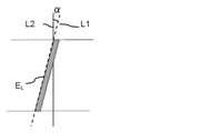
図16および図17は、角度αの説明図である。図15に示すサーボパターンにおいて、サーボパターンA1~A5、C1~C4のように走行方向の上流側に向けて傾斜しているサーボパターンについては、下流側のエッジELの端部2箇所を結ぶ線分(図16中、破線L1)とテープ幅方向(図16中、破線L2)とのなす角度を角度αとする。一方、サーボパターンB1~B5、D1~D4のように走行方向の下流側に向けて傾斜しているサーボパターンについては、下流側のエッジELの端部2箇所を結ぶ線分(図17中、破線L1)とテープ幅方向(図17中、破線L2)とのなす角度を角度αとする。この角度αは、一般にアジマス角と呼ばれ、サーボバンド上に磁化領域(サーボパターン)を形成する際のサーボライトヘッドの設定により定められる。 16 and 17 are explanatory views of the angle α. In the servo pattern shown in FIG. 15, for a servo pattern that is inclined toward the upstream side in the traveling direction such as servo patterns A1 to A5 and C1 to C4, two end portions of the edge EL on the downstream side are connected. The angle formed by the line segment (broken line L1 in FIG. 16) and the tape width direction (broken line L2 in FIG. 16) is defined as the angle α. On the other hand, for servo patterns that are inclined toward the downstream side in the traveling direction, such as servo patterns B1 to B5 and D1 to D4, a line segment connecting two ends of the edge EL on the downstream side (in FIG. 17). , The angle formed by the broken line L1) and the tape width direction (broken line L2 in FIG. 17) is defined as an angle α. This angle α is generally called an azimuth angle, and is determined by setting the servo light head when forming a magnetization region (servo pattern) on the servo band.
サーボバンド上に磁化領域(サーボパターン)を形成する際、サーボパターンが理想的に形成されたならば、上記の磁気テープ幅方向に対して角度αで傾斜したサーボパターンのエッジ形状は、上記のエッジ端部2箇所を結ぶ線分(図16、図17中、破線L1)の形状と一致する。即ち直線になる。したがって、エッジ上の各箇所において、磁気テープの長手方向における理想形状からの位置ずれ幅(以下、単に「位置ずれ幅」とも記載する。)はゼロになる。他方、図18に一例を示すようにサーボパターンのエッジ形状が理想形状からずれてしまう場合がある。上記の差分(L99.9-L0.1)は、サーボパターンのエッジ各位置で理想形状からの位置ずれ幅が小さく、かつエッジ各箇所での位置ずれ幅の値のばらつきが小さいことの指標となり得る値である。差分(L99.9-L0.1)は、以下の方法により求められる値である。
サーボパターンが形成された磁気テープの磁性層表面を磁気力顕微鏡(MFM;Magnetic Force Microscope)で観察する。測定範囲は、サーボパターンが5本含まれる範囲とする。例えば、LTO Ultriumフォーマットテープでは、測定範囲を90μm×90μmとすることにより、AバーストまたはBバーストの5本のサーボパターンを観察することができる。測定範囲を100nmピッチで測定(粗測定)することによりサーボパターン(磁化領域)を抽出する。なお本発明および本明細書において、磁性層表面との語は、磁気テープの磁性層側表面と同義で用いるものとする。
その後、サーボパターンの、走行方向に対して下流側に位置するエッジにおいて磁化領域と非磁化領域との境界を検出するために、上記境界近傍において5nmピッチで測定を行い磁気プロファイルを得る。得られた磁気プロファイルが、磁気テープの幅方向に対して角度α傾斜している場合には、解析ソフトにより磁気テープ幅方向に沿うように(α=0°となるように)回転補正する。その後、解析ソフトにより、5nmピッチで測定された各プロファイルのピーク値の位置座標を算出する。このピーク値の位置座標は、磁化領域と非磁化領域との境界の位置を示している。位置座標は、例えば、走行方向をx座標、幅方向をy座標とするxy座標系により特定される。
理想形状が直線であって直線上のある位置の位置座標が(x,y)=(a,b)である場合を例に取ると、実際に求められたエッジ形状(上記境界の位置座標)が理想形状と一致していたならば、算出される位置座標は、(x,y)=(a,b)となる。この場合、位置ずれ幅はゼロである。これに対し、実際に求められたエッジ形状が理想形状からずれていたならば、上記境界のy=bの位置のx座標は、x=a+cまたはx=a―cとなる。x=a+cとは、例えば走行方向に対して上流側に幅cずれている場合であり、x=a-cとは、例えば走行方向に対して下流側に幅c(即ち上流側を基準にすると-c)ずれている場合である。ここでcが、位置ずれ幅である。即ち、理想形状からのx座標の位置ずれ幅の絶対値が、磁気テープの長手方向における理想形状からの位置ずれ幅である。こうして、5nmピッチでの測定により求められた走行方向の下流側のエッジ各箇所での位置ずれ幅を求める。
各サーボパターンについて得られた値から、解析ソフトにより累積分布関数を得る。得られた累積分布関数から、累積分布関数99.9%の値L99.9と0.1%の値L0.1とを求め、求められた値から各サーボパターンについて差分(L99.9-L0.1)を求める。
以上の測定を、異なる3箇所の測定範囲で行う(測定数N=3)。
各サーボパターンについて得られた差分(L99.9-L0.1)の算術平均を、磁気テープについての上記の差分(L99.9-L0.1)と定義する。
If the servo pattern is ideally formed when the magnetization region (servo pattern) is formed on the servo band, the edge shape of the servo pattern inclined at an angle α with respect to the magnetic tape width direction is described above. It matches the shape of the line segment (broken line L1 in FIGS. 16 and 17) connecting the two edge ends. That is, it becomes a straight line. Therefore, at each location on the edge, the misalignment width from the ideal shape in the longitudinal direction of the magnetic tape (hereinafter, also simply referred to as “misalignment width”) becomes zero. On the other hand, as shown in FIG. 18, the edge shape of the servo pattern may deviate from the ideal shape. The above difference (L 99.9 -L 0.1 ) is that the deviation width from the ideal shape is small at each edge position of the servo pattern, and the variation in the position deviation width value at each edge position is small. It is a value that can be used as an index. The difference (L 99.9 -L 0.1 ) is a value obtained by the following method.
The surface of the magnetic layer of the magnetic tape on which the servo pattern is formed is observed with a magnetic force microscope (MFM). The measurement range is a range including five servo patterns. For example, in the LTO Ultra format tape, by setting the measurement range to 90 μm × 90 μm, five servo patterns of A burst or B burst can be observed. The servo pattern (magnetization region) is extracted by measuring the measurement range at a pitch of 100 nm (coarse measurement). In the present invention and the present specification, the term magnetic layer surface is used synonymously with the magnetic layer side surface of the magnetic tape.
Then, in order to detect the boundary between the magnetized region and the non-magnetized region at the edge of the servo pattern located downstream with respect to the traveling direction, measurement is performed at a pitch of 5 nm in the vicinity of the boundary to obtain a magnetic profile. When the obtained magnetic profile is tilted by an angle α with respect to the width direction of the magnetic tape, the analysis software is used to correct the rotation along the width direction of the magnetic tape (so that α = 0 °). After that, the position coordinates of the peak value of each profile measured at a pitch of 5 nm are calculated by the analysis software. The position coordinates of this peak value indicate the position of the boundary between the magnetized region and the non-magnetized region. The position coordinates are specified by, for example, an xy coordinate system in which the traveling direction is the x coordinate and the width direction is the y coordinate.
Taking the case where the ideal shape is a straight line and the position coordinates of a certain position on the straight line are (x, y) = (a, b), the actually obtained edge shape (position coordinates of the above boundary) If is consistent with the ideal shape, the calculated position coordinates are (x, y) = (a, b). In this case, the misalignment width is zero. On the other hand, if the actually obtained edge shape deviates from the ideal shape, the x-coordinate of the position of y = b at the boundary becomes x = a + c or x = a-c. For example, x = a + c is a case where the width c is deviated to the upstream side with respect to the traveling direction, and x = a−c is, for example, a width c (that is, based on the upstream side) to the downstream side with respect to the traveling direction. Then, -c) is the case. Here, c is the misalignment width. That is, the absolute value of the position deviation width of the x-coordinate from the ideal shape is the position deviation width from the ideal shape in the longitudinal direction of the magnetic tape. In this way, the misalignment width at each point on the downstream side in the traveling direction obtained by the measurement at the 5 nm pitch is obtained.
From the values obtained for each servo pattern, the cumulative distribution function is obtained by analysis software. From the obtained cumulative distribution function, the cumulative distribution function 99.9% value L 99.9 and the 0.1% value L 0.1 were obtained, and the difference (L 99.) was obtained for each servo pattern from the obtained values. 9 -L 0.1 ) is obtained.
The above measurement is performed in three different measurement ranges (measurement number N = 3).
The arithmetic mean of the difference (L 99.9 -L 0.1 ) obtained for each servo pattern is defined as the above difference (L 99.9 -L 0.1 ) for the magnetic tape.
本発明および本明細書におけるサーボパターンのエッジ形状の「理想形状」とは、位置ずれなくサーボパターンが形成された場合のエッジ形状をいう。例えば、一態様では、上記サーボパターンは、磁気テープの幅方向の一方から他方に向かって連続的または不連続に延びる直線状サーボパターンである。なおサーボパターンについての「直線状」とは、エッジ形状の位置ずれは不問として、パターン形状として曲線部分を含まないことをいう。「連続的」とは、傾斜角度の変曲点なく、かつ途切れることなく、テープ幅方向の一方から他方に向かって延びることをいう。磁気テープの幅方向の一方から他方に向かって連続的に延びるサーボパターンの一例は、図15に示したサーボパターンである。これに対し、「不連続」とは、傾斜角度の変曲点が1つ以上あるか、および/または、1箇所以上で途切れて延びていることをいう。傾斜角度の変曲点はあるが途切れずに延びる形状は、いわゆる折れ線形状である。傾斜角度の変曲点が1つで途切れることなくテープ幅方向の一方から他方に向かって延びる不連続なサーボパターンの一例は、図19に示すサーボパターンである。一方、傾斜角度の変曲点なく1箇所で途切れてテープ幅方向の一方から他方に向かって延びる不連続なサーボパターンの一例は、図20に示すサーボパターンである。また、傾斜角度の変曲点が1つで、1箇所で途切れてテープ幅方向の一方から他方に向かって延びる不連続なサーボパターンの一例は、図21に示すサーボパターンである。
テープ幅方向の一方から他方に向かって連続的に延びる直線状サーボパターンについて、エッジ形状の「理想形状」とは、直線状のサーボパターンの走行方向の下流側のエッジの端部2箇所を結ぶ線分の形状(直線形状)である。例えば図15に示した直線状サーボパターンについては、図16または図17中のL1で示した直線の形状である。一方、不連続に延びる直線状サーボパターンについては、理想形状とは、傾斜角度の変曲点がある形状については、傾斜角度が同じ部分の一端から他端を結ぶ線分の形状(直線形状)である。また、1箇所以上で途切れて延びている形状については、連続的に延びている各部分のそれぞれの一端から他端を結ぶ線分の形状(直線形状)である。例えば、図19に示すサーボパターンについては、e1とe2とを結ぶ線分、およびe2とe3とを結ぶ線分である。図20に示すサーボパターンについては、e4とe5とを結ぶ線分、およびe6とe7とを結ぶ線分である。図21に示すサーボパターンについては、e8とe9とを結ぶ線分、およびe10とe11とを結ぶ線分である。
The "ideal shape" of the edge shape of the servo pattern in the present invention and the present specification means the edge shape when the servo pattern is formed without positional deviation. For example, in one aspect, the servo pattern is a linear servo pattern that extends continuously or discontinuously from one side in the width direction of the magnetic tape toward the other. The term "straight line" for the servo pattern means that the pattern shape does not include a curved portion, regardless of the positional deviation of the edge shape. "Continuous" means extending from one side in the tape width direction toward the other without any inflection of the tilt angle and without interruption. An example of a servo pattern that continuously extends from one side in the width direction of the magnetic tape toward the other is the servo pattern shown in FIG. On the other hand, "discontinuity" means that there is one or more inflection points of the inclination angle and / or that the inclination angle is interrupted and extended at one or more points. The shape that has an inflection point of the inclination angle but extends without interruption is a so-called polygonal line shape. An example of a discontinuous servo pattern in which one inflection point of the inclination angle extends from one side in the tape width direction toward the other without interruption is the servo pattern shown in FIG. On the other hand, an example of a discontinuous servo pattern that is interrupted at one point without an inflection of the inclination angle and extends from one side in the tape width direction toward the other is the servo pattern shown in FIG. Further, an example of a discontinuous servo pattern in which the inclination angle has one inflection point and is interrupted at one point and extends from one side in the tape width direction toward the other is the servo pattern shown in FIG.
For a linear servo pattern that extends continuously from one side in the tape width direction to the other, the "ideal shape" of the edge shape connects two ends of the edge on the downstream side in the traveling direction of the linear servo pattern. It is the shape of a line segment (straight line shape). For example, the linear servo pattern shown in FIG. 15 has a linear shape shown by L1 in FIG. 16 or 17. On the other hand, for a linear servo pattern that extends discontinuously, the ideal shape is the shape of a line segment connecting one end to the other end of a portion having the same inclination angle (straight shape) for a shape having an inflection point of the inclination angle. Is. Further, the shape that is interrupted and extended at one or more points is the shape of a line segment (straight line shape) that connects one end to the other end of each of the continuously extending portions. For example, the servo pattern shown in FIG. 19 is a line segment connecting e1 and e2 and a line segment connecting e2 and e3. The servo pattern shown in FIG. 20 is a line segment connecting e4 and e5, and a line segment connecting e6 and e7. The servo pattern shown in FIG. 21 is a line segment connecting e8 and e9, and a line segment connecting e10 and e11.
上記では、直線状サーボパターンを例に説明した。ただし、サーボパターンはエッジ形状の理想形状が曲線形状のサーボパターンであってもよい。例えば走行方向に対して下流側のエッジ形状が理想的には部分円弧形状のサーボパターンについては、この部分円弧の位置座標に対して、走行方向に対して下流側のエッジ形状の磁気力顕微鏡により求められる位置座標により求められる位置ずれ幅から、差分(L99.9-L0.1)を求めることができる。 In the above, the linear servo pattern has been described as an example. However, the servo pattern may be a servo pattern in which the ideal edge shape is a curved shape. For example, for a servo pattern in which the edge shape on the downstream side with respect to the traveling direction is ideally a partial arc shape, a magnetic force microscope with an edge shape on the downstream side with respect to the traveling direction is used with respect to the position coordinates of this partial arc. The difference (L 99.9 -L 0.1 ) can be obtained from the position deviation width obtained by the obtained position coordinates.
以上の測定で用いる磁気力顕微鏡としては、市販の、または公知の構成の磁気力顕微鏡を周波数変調(FM:Frequency Modulation)モードで用いる。磁気力顕微鏡のプローブとしては、例えば、Nanoworld社製SSS-MFMR(公称曲率半径15nm)を用いることができる。磁気力顕微鏡観察時の磁性層表面とプローブ先端との間の距離は、20~50nmの範囲とする。
また、上記解析ソフトとしては、市販の解析ソフト、または公知の演算式を組み込んだ解析ソフトを用いることができる。
As the magnetic force microscope used in the above measurement, a commercially available magnetic force microscope having a known configuration is used in the frequency modulation (FM) mode. As the probe of the magnetic force microscope, for example, SSS-MFMR (nominal radius of curvature of 15 nm) manufactured by Nowold can be used. The distance between the surface of the magnetic layer and the tip of the probe when observed with a magnetic force microscope shall be in the range of 20 to 50 nm.
Further, as the analysis software, commercially available analysis software or analysis software incorporating a known arithmetic expression can be used.
次に、本発明および本明細書において、磁性層の面内方向について測定される屈折率Nxyと磁性層の厚み方向について測定される屈折率Nzとの差分の絶対値ΔNは、以下の方法によって求められる値とする。本発明および本明細書において、「磁性層(の)表面」とは、磁気テープの磁性層側表面と同義である。 Next, in the present invention and the present specification, the absolute value ΔN of the difference between the refractive index Nxy measured in the in-plane direction of the magnetic layer and the refractive index Nz measured in the thickness direction of the magnetic layer is determined by the following method. The value to be obtained. In the present invention and the present specification, "the surface of the magnetic layer" is synonymous with the surface of the magnetic tape on the magnetic layer side.
磁性層の各方向についての屈折率は、分光エリプソメトリーにより2層モデルを用いて求めるものとする。分光エリプソメトリーにより2層モデルを用いて磁性層の屈折率を求めるためには、磁性層と隣接する部分の屈折率の値が用いられる。以下では、非磁性支持体上に非磁性層と磁性層とがこの順に積層された層構成を有する磁気テープについて、磁性層の屈折率NxyおよびNzを求める場合を例に説明する。ただし、本発明の一態様にかかる磁気テープは、非磁性支持体上に非磁性層を介さずに磁性層が直接積層された層構成の磁気テープであることもできる。かかる構成の磁気テープについては、磁性層と非磁性支持体との2層モデルを用いて、以下の方法と同様に磁性層の各方向についての屈折率を求める。また、以下に記載の入射角度は、垂直入射の場合の入射角度を0°としたときの入射角度である。
(1)測定用試料の準備
非磁性支持体の磁性層を有する表面とは反対側の表面上にバックコート層を有する磁気テープについては、磁気テープから切り出した測定用試料のバックコート層を除去した後に測定を行う。バックコート層の除去は、バックコート層を溶媒を用いて溶解する等の公知の方法により行うことができる。溶媒としては、例えばメチルエチルケトンを用いることができる。ただし、バックコート層を除去できる溶媒であればよい。バックコート層除去後の非磁性支持体表面は、エリプソメーターでの測定において、この表面での反射光が検出されないように公知の方法により粗面化する。粗面化は、例えばバックコート層除去後の非磁性支持体表面をサンドペーパーを用いて研磨する等の公知の方法によって行うことができる。バックコート層を持たない磁気テープから切り出した測定用試料については、磁性層を有する表面とは反対側の非磁性支持体表面について、粗面化を行う。
また、下記の非磁性層の屈折率測定のためには、更に磁性層を除去して非磁性層表面を露出させる。下記の非磁性支持体の屈折率測定のためには、更に非磁性層も除去して非磁性支持体の磁性層側の表面を露出させる。各層の除去は、バックコート層の除去について記載したように、公知の方法により行うことができる。なお以下に記載の長手方向とは、測定用試料が切り出される前に磁気テープに含まれていたときに、磁気テープの長手方向であった方向をいうものとする。この点は、以下に記載のその他の方向についても、同様である。
(2)磁性層の屈折率測定
エリプソメーターを用いて、入射角度を65°、70°および75°とし、長手方向から磁性層表面にビーム径300μmの入射光を照射することにより、Δ(s偏光とp偏光の位相差)およびΨ(s偏光とp偏光の振幅比)を測定する。測定は入射光の波長を400~700nmの範囲で1.5nm刻みで変化させて行い、各波長について測定値を求める。
各波長における磁性層のΔおよびΨの測定値、下記方法により求められる各方向における非磁性層の屈折率、ならびに磁性層の厚みを用いて、以下のように2層モデルによって各波長における磁性層の屈折率を求める。
2層モデルの基板である第0層を非磁性層とし、第1層を磁性層とする。空気/磁性層と磁性層/非磁性層の界面の反射のみを考慮し非磁性層の裏面反射の影響はないものと見做して2層モデルを作成する。得られた測定値に最も整合する第1層の屈折率を最小二乗法によってフィッティングにより求める。フィッティングの結果から得られた波長600nmにおける値として、長手方向における磁性層の屈折率Nx、および長手方向から入射光を入射させて測定した磁性層の厚み方向における屈折率Nz1を求める。
入射光を入射させる方向を磁気テープの幅方向とする点以外は上記と同様として、フィッティングの結果から得られた波長600nmにおける値として、幅方向における磁性層の屈折率Ny、および幅方向から入射光を入射させて測定した磁性層の厚み方向における屈折率Nz2を求める。
フィッティングは、以下の手法により行う。
一般的に「複素屈折率n=η+iκ」である。ここで、ηは屈折率の実数部であり、κは消光係数であり、iは虚数である。複素誘電率ε=ε1+iε2 (ε1とε2はクラマース・クローニッヒの関係を満たしている)とε1=η2-κ2、ε2=2ηκの関係にあり、NxおよびNz1算出の際は、Nxの複素誘電率をεx=εx1+iεx2、Nz1の複素誘電率をεz1=εz11+iεz12とする。
εx2を1つのガウシアンとし、ピーク位置が5.8~5.1eV、σが4~3.5 eVの任意の点を出発点とし、測定波長域(400~700nm)の外に誘電率にオフセットとなるパラメータを置き、測定値を最小二乗フィッティングすることによりNxを求める。同様に、εz12はピーク位置が3.2~2.9eV、σが1.5~1.2eVの任意の点を出発点とし、オフセットパラメータを置き、測定値を最小二乗フィッティングすることによりNz1を求める。NyおよびNz2も同様に求める。磁性層の面内方向について測定される屈折率Nxyは、「Nxy=(Nx+Ny)/2」として求める。磁性層の厚み方向について測定される屈折率Nzは、「Nz=(Nz1+Nz2)/2」として求める。求められたNxyとNzから、これらの差分の絶対値ΔNを求める。
(3)非磁性層の屈折率測定
以下の点を除き、上記方法と同様に非磁性層の波長600nmにおける屈折率(長手方向における屈折率、幅方向における屈折率、長手方向から入射光を入射させて測定される厚み方向における屈折率、および幅方向から入射光を入射させて測定される厚み方向における屈折率)を求める。
入射光の波長は、250~700nmの範囲で1.5nm刻みで変化させる。
非磁性層と非磁性支持体の2層モデルを用いて、2層モデルの基板である第0層を非磁性支持体とし、第1層を非磁性層とする。空気/非磁性層と非磁性層/非磁性支持体の界面の反射のみを考慮し非磁性支持体の裏面反射の影響はないものと見做して2層モデルを作成する。
フィッティングにおいて、複素誘電率の虚部(ε2)に、7か所のピーク(0.6eV、2.3eV、2.9eV、3.6eV、4.6eV、5.0eV、6.0eV)を仮定し、測定波長域(250~700nm)の外に誘電率にオフセットとなるパラメータを置く。
(4)非磁性支持体の屈折率測定
2層モデルにより非磁性層の屈折率を求めるために用いられる非磁性支持体の波長600nmにおける屈折率(長手方向における屈折率、幅方向における屈折率、長手方向から入射光を入射させて測定される厚み方向における屈折率、および幅方向から入射光を入射させて測定される厚み方向における屈折率)は、以下の点を除き、磁性層の屈折率測定のための上記方法と同様に求める。
2層モデルを用いず、表面反射のみの1層モデルを用いる。
フィッティングは、コーシーモデル(n=A+B/λ2、nは屈折率、AおよびBはそれぞれフィッティングにより定まる定数、λは波長)により行う。
The refractive index in each direction of the magnetic layer shall be determined by spectroscopic ellipsometry using a two-layer model. In order to obtain the refractive index of the magnetic layer using the two-layer model by spectroscopic ellipsometry, the value of the refractive index of the portion adjacent to the magnetic layer is used. Hereinafter, for a magnetic tape having a layer structure in which a non-magnetic layer and a magnetic layer are laminated in this order on a non-magnetic support, a case where the refractive indexes Nxy and Nz of the magnetic layer are obtained will be described as an example. However, the magnetic tape according to one aspect of the present invention may be a magnetic tape having a layer structure in which a magnetic layer is directly laminated on a non-magnetic support without a non-magnetic layer. For a magnetic tape having such a configuration, a two-layer model of a magnetic layer and a non-magnetic support is used to determine the refractive index in each direction of the magnetic layer in the same manner as in the following method. Further, the incident angle described below is an incident angle when the incident angle in the case of vertical incident is 0 °.
(1) Preparation of measurement sample For a magnetic tape having a backcoat layer on the surface opposite to the surface of the non-magnetic support having a magnetic layer, the backcoat layer of the measurement sample cut out from the magnetic tape is removed. After that, the measurement is performed. The backcoat layer can be removed by a known method such as dissolving the backcoat layer with a solvent. As the solvent, for example, methyl ethyl ketone can be used. However, any solvent may be used as long as it can remove the backcoat layer. The surface of the non-magnetic support after removing the backcoat layer is roughened by a known method so that the reflected light on this surface is not detected in the measurement with an ellipsometer. The roughening can be performed by a known method such as polishing the surface of the non-magnetic support after removing the backcoat layer with sandpaper. For the measurement sample cut out from the magnetic tape having no backcoat layer, the surface of the non-magnetic support opposite to the surface having the magnetic layer is roughened.
Further, in order to measure the refractive index of the non-magnetic layer described below, the magnetic layer is further removed to expose the surface of the non-magnetic layer. In order to measure the refractive index of the non-magnetic support described below, the non-magnetic layer is also removed to expose the surface of the non-magnetic support on the magnetic layer side. The removal of each layer can be performed by a known method as described for the removal of the backcoat layer. The longitudinal direction described below means the direction that was the longitudinal direction of the magnetic tape when it was contained in the magnetic tape before the sample for measurement was cut out. This point is the same for the other directions described below.
(2) Measurement of Refractive Index of Magnetic Layer Using an ellipsometer, the incident angles are set to 65 °, 70 ° and 75 °, and the surface of the magnetic layer is irradiated with incident light with a beam diameter of 300 μm from the longitudinal direction to make Δ (s). (Phase difference between polarization and p-polarization) and Ψ (amplitude ratio of s-polarization and p-polarization) are measured. The measurement is performed by changing the wavelength of the incident light in the range of 400 to 700 nm in increments of 1.5 nm, and the measured value is obtained for each wavelength.
Using the measured values of Δ and Ψ of the magnetic layer at each wavelength, the refractive index of the non-magnetic layer in each direction obtained by the following method, and the thickness of the magnetic layer, the magnetic layer at each wavelength is calculated by a two-layer model as follows. The refractive index of is calculated.
The 0th layer, which is the substrate of the 2-layer model, is a non-magnetic layer, and the 1st layer is a magnetic layer. A two-layer model is created by considering only the reflection at the interface between the air / magnetic layer and the magnetic layer / non-magnetic layer and assuming that there is no influence of the back surface reflection of the non-magnetic layer. The refractive index of the first layer that best matches the obtained measured value is obtained by fitting by the method of least squares. As a value at a wavelength of 600 nm obtained from the fitting result, the refractive index Nx of the magnetic layer in the longitudinal direction and the refractive index Nz 1 in the thickness direction of the magnetic layer measured by incident light from the longitudinal direction are obtained.
Similar to the above except that the direction in which the incident light is incident is the width direction of the magnetic tape, the value at the wavelength of 600 nm obtained from the fitting result is the refractive index Ny of the magnetic layer in the width direction and the incident from the width direction. The refractive index Nz 2 in the thickness direction of the magnetic layer measured by incident light is obtained.
Fitting is performed by the following method.
Generally, "complex refractive index n = η + iκ". Here, η is the real part of the refractive index, κ is the extinction coefficient, and i is the imaginary number. The complex permittivity ε = ε1 + iε2 (ε1 and ε2 satisfy the Kramers-Kronig relationship) and ε1 = η 2 -κ 2 and ε2 = 2ηκ, and when calculating Nx and Nz 1 , the complex of Nx The permittivity is ε x =
Let ε x 2 be one Gaussian, and start from any point where the peak position is 5.8 to 5.1 eV and σ is 4 to 3.5 eV, and the permittivity is outside the measurement wavelength range (400 to 700 nm). Nx is obtained by setting a parameter to be an offset in and fitting the measured value to the least squares. Similarly,
(3) Refractive index measurement of non-magnetic layer Except for the following points, the refractive index of the non-magnetic layer at a wavelength of 600 nm (refractive index in the longitudinal direction, refractive index in the width direction, incident light is incident from the longitudinal direction). The refractive index in the thickness direction and the refractive index in the thickness direction measured by incident light from the width direction are obtained.
The wavelength of the incident light is changed in the range of 250 to 700 nm in increments of 1.5 nm.
Using a two-layer model of a non-magnetic layer and a non-magnetic support, the 0th layer, which is the substrate of the 2-layer model, is used as the non-magnetic support, and the first layer is used as the non-magnetic layer. A two-layer model is created by considering only the reflection at the interface between the air / non-magnetic layer and the non-magnetic layer / non-magnetic support and assuming that there is no influence of the back surface reflection of the non-magnetic support.
In the fitting, 7 peaks (0.6 eV, 2.3 eV, 2.9 eV, 3.6 eV, 4.6 eV, 5.0 eV, 6.0 eV) are assumed in the imaginary part (ε2) of the complex permittivity. Then, a parameter that is offset to the permittivity is set outside the measurement wavelength range (250 to 700 nm).
(4) Refractive index measurement of non-magnetic support The refractive index of the non-magnetic support used to obtain the refractive index of the non-magnetic layer by the two-layer model at a wavelength of 600 nm (refractive index in the longitudinal direction, refractive index in the width direction, The refractive index in the thickness direction measured by incident light incident from the longitudinal direction and the refractive index in the thickness direction measured by incident light incident from the width direction) are the refractive indexes of the magnetic layer except for the following points. It is obtained in the same manner as the above method for measurement.
Instead of using a two-layer model, use a one-layer model with only surface reflection.
The fitting is performed by the Cauchy model (n = A + B / λ 2 , n is the refractive index, A and B are constants determined by the fitting, and λ is the wavelength).
磁気テープに記録されたデータを読み取る際、磁性層表面と読取素子とが接触して磁性層表面が削れることにより、削れ屑(デブリ(debris)と呼ばれることがある。)が発生すると考えられる。この削れ屑が磁性層表面と読取素子との間に多く介在するほど、磁性層表面と読取素子との接触状態は不安定になってしまう。このことが、読取素子と読取対象トラックとの相対位置の変動(相対位置変動)を大きくする原因になると、本発明者らは推察している。これに対し、上記方法により求められるΔNは、磁性層の表層領域における強磁性粉末の存在状態の指標となり得る値と考えている。このΔNは、磁性層における強磁性粉末の配向状態に加えて、結合剤の存在状態、強磁性粉末の密度分布等の各種要因の影響を受ける値と推察される。そして、各種要因を制御することによってΔNを0.25以上0.40以下とした磁性層は、磁性層表面の強度が高く、読取素子と接触しても削れ難いと考えられる。その結果、磁性層表面が削れて発生した削れ屑が原因で磁性層表面と読取素子との接触状態が不安定になることを抑制できることが、上記の相対位置変動の発生を抑制できることに寄与すると推察される。このことが、複数の読取素子により得られた読取結果の各々に対して、より適した波形等化処理を施すことを可能にすることに寄与し、良好な再生品質を確保できるずれ量(トラックオフセット量)の許容量を大きくすることにつながると本発明者らは考えている。
また、先に記載したように、サーボパターンが設計形状により近い形状で形成されていることも、良好な再生品質を確保できるずれ量(トラックオフセット量)の許容量を大きくすることにつながると考えられる。この点に関して、上記の差分(L99.9-L0.1)は、サーボパターンの形状に関する指標であって、この差分(L99.9-L0.1)が180nm以下であることも、良好な再生品質を確保できるずれ量(トラックオフセット量)の許容量を大きくすることに寄与すると本発明者らは考えている。磁性層に形成されるサーボパターンの形状については、サーボライトヘッドが磁場を印加して磁性層に形成しようとするサーボパターン(磁化領域)の形状と、実際に磁性層に形成されるサーボパターンの形状とのずれを抑制するための手段の1つとしては、サーボライトヘッドの能力を高めること、具体的には磁場(漏れ磁界)が大きなサーボライトヘッドを使用することが考えられる。また、サーボライトヘッドが磁性層表面と接触しながら磁性層に磁場を印加してサーボパターンを形成する際にも、削れ屑(デブリ)が発生すると考えられる。この削れ屑が磁性層表面とサーボライトヘッドとの間に多く介在するほど、磁性層表面とサーボライトヘッドとの接触状態は不安定になってしまう。このことが、サーボライトヘッドが磁場を印加して磁性層に形成しようとするサーボパターン(磁化領域)の形状と、実際に磁性層に形成されるサーボパターンの形状とのずれが発生する原因になると、本発明者らは推察している。これに対し、ΔNが0.25以上0.40以下である磁性層がサーボライトヘッドと接触しても削れ難いことは、設計形状により近い形状のサーボパターンを形成すること、即ち、上記の差分(L99.9-L0.1)を180nm以下にすること、に寄与すると、本発明者らは考えている。
ただし、以上は本発明者らの推察であって、本発明を何ら限定するものではない。
When reading the data recorded on the magnetic tape, it is considered that shavings (sometimes called debris) are generated by the contact between the surface of the magnetic layer and the reading element and the scraping of the surface of the magnetic layer. The more the shavings intervene between the surface of the magnetic layer and the reading element, the more unstable the contact state between the surface of the magnetic layer and the reading element. The present inventors speculate that this causes a large variation in the relative position (relative position variation) between the reading element and the track to be read. On the other hand, ΔN obtained by the above method is considered to be a value that can be an index of the existence state of the ferromagnetic powder in the surface layer region of the magnetic layer. It is presumed that this ΔN is affected by various factors such as the presence state of the binder and the density distribution of the ferromagnetic powder, in addition to the orientation state of the ferromagnetic powder in the magnetic layer. It is considered that the magnetic layer having ΔN of 0.25 or more and 0.40 or less by controlling various factors has high strength of the surface of the magnetic layer and is hard to be scraped even if it comes into contact with the reading element. As a result, it is possible to suppress the unstable contact state between the magnetic layer surface and the reading element due to the shavings generated by scraping the surface of the magnetic layer, which contributes to suppressing the occurrence of the above-mentioned relative position fluctuation. It is inferred. This contributes to making it possible to perform more suitable waveform equalization processing for each of the reading results obtained by the plurality of reading elements, and the amount of deviation (track) that can ensure good reproduction quality. The present inventors believe that this will lead to an increase in the allowable amount of offset amount).
In addition, as described above, the fact that the servo pattern is formed in a shape closer to the design shape also leads to an increase in the allowable amount of deviation (track offset amount) that can ensure good reproduction quality. Be done. In this regard, the above difference (L 99.9 -L 0.1 ) is an index regarding the shape of the servo pattern, and this difference (L 99.9 -L 0.1 ) may be 180 nm or less. The present inventors consider that it contributes to increasing the allowable amount of the deviation amount (track offset amount) that can ensure good reproduction quality. Regarding the shape of the servo pattern formed on the magnetic layer, the shape of the servo pattern (magnetization region) that the servo light head tries to form on the magnetic layer by applying a magnetic field and the shape of the servo pattern actually formed on the magnetic layer As one of the means for suppressing the deviation from the shape, it is conceivable to enhance the ability of the servo light head, specifically, to use a servo light head having a large magnetic field (leakage magnetic field). It is also considered that shavings (debris) are generated when the servo light head is in contact with the surface of the magnetic layer and a magnetic field is applied to the magnetic layer to form a servo pattern. The more the shavings intervene between the surface of the magnetic layer and the servo light head, the more unstable the contact state between the surface of the magnetic layer and the servo light head. This causes a discrepancy between the shape of the servo pattern (magnetization region) that the servo light head tries to form on the magnetic layer by applying a magnetic field and the shape of the servo pattern that is actually formed on the magnetic layer. Then, the present inventors infer. On the other hand, the fact that the magnetic layer having ΔN of 0.25 or more and 0.40 or less is difficult to scrape even if it comes into contact with the servo light head means that a servo pattern having a shape closer to the design shape is formed, that is, the above difference. The present inventors believe that it contributes to making (L 99.9 -L 0.1 ) 180 nm or less.
However, the above is the inference of the present inventors and does not limit the present invention in any way.
以下、上記磁気テープについて、更に詳細に説明する。 Hereinafter, the magnetic tape will be described in more detail.
<磁性層のΔN>
上記磁気テープの磁性層のΔNは、0.25以上0.40以下である。良好な再生品質を確保できるずれ量(トラックオフセット量)の許容量をより大きくする観点からは、ΔNは0.25以上0.35以下であることが好ましい。ΔNを調整するための手段の具体的態様は、後述する。
<ΔN of magnetic layer>
The ΔN of the magnetic layer of the magnetic tape is 0.25 or more and 0.40 or less. From the viewpoint of increasing the allowable amount of the deviation amount (track offset amount) that can ensure good reproduction quality, ΔN is preferably 0.25 or more and 0.35 or less. Specific embodiments of the means for adjusting ΔN will be described later.
ΔNは、NxyとNzとの差分の絶対値である。Nxyは磁性層の面内方向について測定される屈折率であり、Nzは磁性層の厚み方向について測定される屈折率である。一態様では、Nxy>Nzであることができ、他の一態様ではNxy<Nzであることができる。磁気テープの電磁変換特性の観点からは、Nxy>Nzであることが好ましく、したがってNxyとNzとの差分(Nxy-Nz)が0.25以上0.40以下であることが好ましく、0.25以上0.35以下であることがより好ましい。一態様では、Nxyは、例えば1.50~2.50の範囲であることができる。一態様では、Nzは、例えば 1.30~2.50の範囲であることができる。ただし、上記磁気テープは、ΔNが0.25以上0.40以下の範囲にあればよく、NxyおよびNzは上記の例示した範囲に限定されない。 ΔN is the absolute value of the difference between Nxy and Nz. Nxy is the refractive index measured in the in-plane direction of the magnetic layer, and Nz is the refractive index measured in the thickness direction of the magnetic layer. In one aspect it can be Nxy> Nz and in the other aspect it can be Nxy <Nz. From the viewpoint of the electromagnetic conversion characteristics of the magnetic tape, it is preferable that Nxy> Nz, and therefore the difference (Nxy-Nz) between Nxy and Nz is preferably 0.25 or more and 0.40 or less, and 0.25. It is more preferably 0.35 or less. In one aspect, Nxy can be, for example, in the range of 1.50 to 2.50. In one aspect, Nz can be, for example, in the range of 1.30-2.50. However, the magnetic tape may have ΔN in the range of 0.25 or more and 0.40 or less, and Nxy and Nz are not limited to the above-exemplified range.
以上説明したΔNを調整するための各種手段については後述する。 Various means for adjusting ΔN described above will be described later.
<差分(L99.9-L0.1)>
上記差分(L99.9-L0.1)は、180nm以下である。このことも、良好な再生品質を確保できるずれ量(トラックオフセット量)の許容量を大きくすることに寄与すると推察される。以上の観点からは、上記差分(L99.9-L0.1)は、170nm以下であることが好ましく、160nm以下であることがより好ましく、150nm以下であることが更に好ましい。また、上記差分(L99.9-L0.1)は、例えば、50nm以上、60nm以上、70nm以上、80nm以上、90nm以上または100nm以上であることができる。ただし、上記差分(L99.9-L0.1)の値が小さいほど、良好な再生品質を確保できるずれ量(トラックオフセット量)の許容量を大きくするうえで好ましいと考えられるため、上記差分(L99.9-L0.1)は上記で例示した下限を下回ってもよい。
<Difference (L 99.9 -L 0.1 )>
The above difference (L 99.9 -L 0.1 ) is 180 nm or less. It is presumed that this also contributes to increasing the allowable amount of deviation amount (track offset amount) that can ensure good reproduction quality. From the above viewpoint, the difference (L 99.9 -L 0.1 ) is preferably 170 nm or less, more preferably 160 nm or less, and further preferably 150 nm or less. Further, the difference (L 99.9 -L 0.1 ) can be, for example, 50 nm or more, 60 nm or more, 70 nm or more, 80 nm or more, 90 nm or more, or 100 nm or more. However, it is considered that the smaller the value of the above difference (L 99.9 -L 0.1 ) is, the more preferable it is to increase the allowable amount of the deviation amount (track offset amount) that can ensure good reproduction quality. The difference (L 99.9 -L 0.1 ) may be below the lower limit exemplified above.
次に、上記磁気テープの磁性層等について、更に説明する。 Next, the magnetic layer and the like of the magnetic tape will be further described.
<磁性層>
(強磁性粉末)
磁性層は、強磁性粉末および結合剤を含む。磁性層に含まれる強磁性粉末としては、各種磁気記録媒体の磁性層において用いられる強磁性粉末として公知の強磁性粉末を使用することができる。強磁性粉末として平均粒子サイズの小さいものを使用することは記録密度向上の観点から好ましい。この点から、強磁性粉末の平均粒子サイズは50nm以下であることが好ましく、45nm以下であることがより好ましく、40nm以下であることが更に好ましく、35nm以下であることが一層好ましく、30nm以下であることがより一層好ましく、25nm以下であることが更に一層好ましく、20nm以下であることがなお一層好ましい。一方、磁化の安定性の観点からは、強磁性粉末の平均粒子サイズは5nm以上であることが好ましく、8nm以上であることがより好ましく、10nm以上であることが更に好ましく、15nm以上であることが一層好ましく、20nm以上であることがより一層好ましい。
<Magnetic layer>
(Ferromagnetic powder)
The magnetic layer contains a ferromagnetic powder and a binder. As the ferromagnetic powder contained in the magnetic layer, a ferromagnetic powder known as a ferromagnetic powder used in the magnetic layer of various magnetic recording media can be used. It is preferable to use a ferromagnetic powder having a small average particle size from the viewpoint of improving the recording density. From this point, the average particle size of the ferromagnetic powder is preferably 50 nm or less, more preferably 45 nm or less, further preferably 40 nm or less, further preferably 35 nm or less, and more preferably 30 nm or less. It is even more preferably 25 nm or less, and even more preferably 20 nm or less. On the other hand, from the viewpoint of the stability of magnetization, the average particle size of the ferromagnetic powder is preferably 5 nm or more, more preferably 8 nm or more, further preferably 10 nm or more, and further preferably 15 nm or more. Is more preferable, and 20 nm or more is even more preferable.
-六方晶フェライト粉末-
強磁性粉末の好ましい具体例としては、六方晶フェライト粉末を挙げることができる。六方晶フェライト粉末の詳細については、例えば、特開2011-225417号公報の段落0012~0030、特開2011-216149号公報の段落0134~0136、特開2012-204726号公報の段落0013~0030および特開2015-127985号公報の段落0029~0084を参照できる。
-Hexagonal ferrite powder-
Hexagonal ferrite powder can be mentioned as a preferable specific example of the ferromagnetic powder. For details of the hexagonal ferrite powder, for example, paragraphs 0012 to 0030 of JP 2011-225417, paragraphs 0134 to 0136 of JP 2011-216149, paragraphs 0013 to 0030 of JP 2012-204726 and References can be made to paragraphs 0029 to 0084 of JP-A-2015-127985.
本発明および本明細書において、「六方晶フェライト粉末」とは、X線回折分析によって、主相として六方晶フェライト型の結晶構造が検出される強磁性粉末をいうものとする。主相とは、X線回折分析によって得られるX線回折スペクトルにおいて最も高強度の回折ピークが帰属する構造をいう。例えば、X線回折分析によって得られるX線回折スペクトルにおいて最も高強度の回折ピークが六方晶フェライト型の結晶構造に帰属される場合、六方晶フェライト型の結晶構造が主相として検出されたと判断するものとする。X線回折分析によって単一の構造のみが検出された場合には、この検出された構造を主相とする。六方晶フェライト型の結晶構造は、構成原子として、少なくとも鉄原子、二価金属原子および酸素原子を含む。二価金属原子とは、イオンとして二価のカチオンになり得る金属原子であり、ストロンチウム原子、バリウム原子、カルシウム原子等のアルカリ土類金属原子、鉛原子等を挙げることができる。本発明および本明細書において、六方晶ストロンチウムフェライト粉末とは、この粉末に含まれる主な二価金属原子がストロンチウム原子であるものをいい、六方晶バリウムフェライト粉末とは、この粉末に含まれる主な二価金属原子がバリウム原子であるものをいう。主な二価金属原子とは、この粉末に含まれる二価金属原子の中で、原子%基準で最も多くを占める二価金属原子をいうものとする。ただし、上記の二価金属原子には、希土類原子は包含されないものとする。本発明および本明細書における「希土類原子」は、スカンジウム原子(Sc)、イットリウム原子(Y)、およびランタノイド原子からなる群から選択される。ランタノイド原子は、ランタン原子(La)、セリウム原子(Ce)、プラセオジム原子(Pr)、ネオジム原子(Nd)、プロメチウム原子(Pm)、サマリウム原子(Sm)、ユウロピウム原子(Eu)、ガドリニウム原子(Gd)、テルビウム原子(Tb)、ジスプロシウム原子(Dy)、ホルミウム原子(Ho)、エルビウム原子(Er)、ツリウム原子(Tm)、イッテルビウム原子(Yb)、およびルテチウム原子(Lu)からなる群から選択される。 In the present invention and the present specification, the "hexagonal ferrite powder" refers to a ferromagnetic powder in which a hexagonal ferrite type crystal structure is detected as a main phase by X-ray diffraction analysis. The main phase refers to a structure to which the highest intensity diffraction peak belongs in the X-ray diffraction spectrum obtained by X-ray diffraction analysis. For example, when the highest intensity diffraction peak is attributed to the hexagonal ferrite type crystal structure in the X-ray diffraction spectrum obtained by X-ray diffraction analysis, it is determined that the hexagonal ferrite type crystal structure is detected as the main phase. It shall be. When only a single structure is detected by X-ray diffraction analysis, this detected structure is used as the main phase. The hexagonal ferrite type crystal structure contains at least iron atoms, divalent metal atoms and oxygen atoms as constituent atoms. The divalent metal atom is a metal atom that can be a divalent cation as an ion, and examples thereof include an alkaline earth metal atom such as a strontium atom, a barium atom, and a calcium atom, and a lead atom. In the present invention and the present specification, the hexagonal strontium ferrite powder means that the main divalent metal atom contained in this powder is a strontium atom, and the hexagonal barium ferrite powder is the main contained in this powder. A divalent metal atom is a barium atom. The main divalent metal atom is a divalent metal atom that occupies the largest amount on an atomic% basis among the divalent metal atoms contained in this powder. However, rare earth atoms are not included in the above divalent metal atoms. The "rare earth atom" in the present invention and the present specification is selected from the group consisting of a scandium atom (Sc), a yttrium atom (Y), and a lanthanoid atom. The lanthanoid atoms are lanthanum atom (La), cerium atom (Ce), placeodium atom (Pr), neodymium atom (Nd), promethium atom (Pm), samarium atom (Sm), uropyum atom (Eu), gadrinium atom (Gd). ), Terbium atom (Tb), dysprosium atom (Dy), formium atom (Ho), erbium atom (Er), thulium atom (Tm), ytterbium atom (Yb), and lutetium atom (Lu). To.
以下に、六方晶フェライト粉末の一態様である六方晶ストロンチウムフェライト粉末について、更に詳細に説明する。 Hereinafter, the hexagonal strontium ferrite powder, which is one aspect of the hexagonal ferrite powder, will be described in more detail.
六方晶ストロンチウムフェライト粉末の活性化体積は、好ましくは800~1600nm3の範囲である。上記範囲の活性化体積を示す微粒子化された六方晶ストロンチウムフェライト粉末は、優れた電磁変換特性を発揮する磁気テープの作製のために好適である。六方晶ストロンチウムフェライト粉末の活性化体積は、好ましくは800nm3以上であり、例えば850nm3以上であることもできる。また、電磁変換特性の更なる向上の観点から、六方晶ストロンチウムフェライト粉末の活性化体積は、1500nm3以下であることがより好ましく、1400nm3以下であることが更に好ましく、1300nm3以下であることが一層好ましく、1200nm3以下であることがより一層好ましく、1100nm3以下であることが更により一層好ましい。六方晶バリウムフェライト粉末の活性化体積についても、同様である。 The activated volume of the hexagonal strontium ferrite powder is preferably in the range of 800 to 1600 nm 3 . The finely divided hexagonal strontium ferrite powder exhibiting the activated volume in the above range is suitable for producing a magnetic tape exhibiting excellent electromagnetic conversion characteristics. The activated volume of the hexagonal strontium ferrite powder is preferably 800 nm 3 or more, and can be, for example, 850 nm 3 or more. Further, from the viewpoint of further improving the electromagnetic conversion characteristics, the activated volume of the hexagonal strontium ferrite powder is more preferably 1500 nm 3 or less, further preferably 1400 nm 3 or less, and 1300 nm 3 or less. Is even more preferable, and it is even more preferably 1200 nm 3 or less, and even more preferably 1100 nm 3 or less. The same applies to the activated volume of the hexagonal barium ferrite powder.
「活性化体積」とは、磁化反転の単位であって、粒子の磁気的な大きさを示す指標である。本発明および本明細書に記載の活性化体積および後述の異方性定数Kuは、振動試料型磁束計を用いて保磁力Hc測定部の磁場スイープ速度3分と30分とで測定し(測定温度:23℃±1℃)、以下のHcと活性化体積Vとの関係式から求められる値である。なお異方性定数Kuの単位に関して、1erg/cc=1.0×10-1J/m3である。
Hc=2Ku/Ms{1-[(kT/KuV)ln(At/0.693)]1/2}
[上記式中、Ku:異方性定数(単位:J/m3)、Ms:飽和磁化(単位:kA/m)、k:ボルツマン定数、T:絶対温度(単位:K)、V:活性化体積(単位:cm3)、A:スピン歳差周波数(単位:s-1)、t:磁界反転時間(単位:s)]
The "activated volume" is a unit of magnetization reversal and is an index showing the magnetic size of a particle. The activated volume described in the present invention and the present specification and the anisotropic constant Ku described later are measured using a vibration sample type magnetic flux meter at magnetic field sweep speeds of 3 minutes and 30 minutes in the coercive force Hc measuring unit (measurement). Temperature: 23 ° C ± 1 ° C), which is a value obtained from the following relational expression between Hc and activated volume V. Regarding the unit of the anisotropy constant Ku, 1 erg / cc = 1.0 × 10 -1 J / m 3 .
Hc = 2Ku / Ms {1-[(kT / KuV) ln (At / 0.693)] 1/2 }
[In the above formula, Ku: anisotropic constant (unit: J / m 3 ), Ms: saturation magnetization (unit: kA / m), k: Boltzmann constant, T: absolute temperature (unit: K), V: activity. Volume (unit: cm 3 ), A: Spin magnetization frequency (unit: s -1 ), t: Magnetic field reversal time (unit: s)]
熱揺らぎの低減、換言すれば熱的安定性の向上の指標としては、異方性定数Kuを挙げることができる。六方晶ストロンチウムフェライト粉末は、好ましくは1.8×10⁵J/m3以上のKuを有することができ、より好ましくは2.0×105J/m3以上のKuを有することができる。また、六方晶ストロンチウムフェライト粉末のKuは、例えば2.5×105J/m3以下であることができる。ただしKuが高いほど熱的安定性が高いことを意味し好ましいため、上記例示した値に限定されるものではない。 Anisotropy constant Ku can be mentioned as an index for reducing thermal fluctuation, in other words, improving thermal stability. The hexagonal strontium ferrite powder can preferably have a Ku of 1.8 × 10 5 J / m 3 or more, and more preferably 2.0 × 10⁵ J / m 3 or more. Further, the Ku of the hexagonal strontium ferrite powder can be, for example, 2.5 × 10⁵ J / m 3 or less. However, the higher the Ku, the higher the thermal stability, which is preferable, and therefore, the value is not limited to the above-exemplified values.
六方晶ストロンチウムフェライト粉末は、希土類原子を含んでいてもよく、含まなくてもよい。六方晶ストロンチウムフェライト粉末が希土類原子を含む場合、鉄原子100原子%に対して、0.5~5.0原子%の含有率(バルク含有率)で希土類原子を含むことが好ましい。希土類原子を含む六方晶ストロンチウムフェライト粉末は、一態様では、希土類原子表層部偏在性を有することができる。本発明および本明細書における「希土類原子表層部偏在性」とは、六方晶ストロンチウムフェライト粉末を酸により部分溶解して得られた溶解液中の鉄原子100原子%に対する希土類原子含有率(以下、「希土類原子表層部含有率」または希土類原子に関して単に「表層部含有率」と記載する。)が、六方晶ストロンチウムフェライト粉末を酸により全溶解して得られた溶解液中の鉄原子100原子%に対する希土類原子含有率(以下、「希土類原子バルク含有率」または希土類原子に関して単に「バルク含有率」と記載する。)と、
希土類原子表層部含有率/希土類原子バルク含有率>1.0
の比率を満たすことを意味する。後述の六方晶フェライト粉末の希土類原子含有率とは、希土類原子バルク含有率と同義である。これに対し、酸を用いる部分溶解は六方晶ストロンチウムフェライト粉末を構成する粒子の表層部を溶解するため、部分溶解により得られる溶解液中の希土類原子含有率とは、六方晶ストロンチウムフェライト粉末を構成する粒子の表層部における希土類原子含有率である。希土類原子表層部含有率が、「希土類原子表層部含有率/希土類原子バルク含有率>1.0」の比率を満たすことは、六方晶ストロンチウムフェライト粉末を構成する粒子において、希土類原子が表層部に偏在(即ち内部より多く存在)していることを意味する。本発明および本明細書における表層部とは、六方晶ストロンチウムフェライト粉末を構成する粒子の表面から内部に向かう一部領域を意味する。
The hexagonal strontium ferrite powder may or may not contain rare earth atoms. When the hexagonal strontium ferrite powder contains rare earth atoms, it is preferable that the hexagonal strontium ferrite powder contains rare earth atoms at a content of 0.5 to 5.0 atomic% (bulk content) with respect to 100 atomic% of iron atoms. In one aspect, the hexagonal strontium ferrite powder containing a rare earth atom can have uneven distribution on the surface layer of the rare earth atom. The "uneven distribution of the surface layer of rare earth atoms" in the present invention and the present specification refers to the rare earth atom content with respect to 100 atomic% of iron atoms in the solution obtained by partially dissolving hexagonal strontium ferrite powder with an acid (hereinafter referred to as "rare earth atom content"). “Rare earth atom surface layer content” or simply “surface layer content” for rare earth atoms) is 100 atomic% of iron atoms in the solution obtained by completely dissolving hexagonal strontium ferrite powder with an acid. Rare earth atom content (hereinafter referred to as "rare earth atom bulk content" or simply referred to as "bulk content" for rare earth atoms).
Rare earth atom surface layer content / Rare earth atom bulk content> 1.0
Means to meet the ratio of. The rare earth atom content of the hexagonal ferrite powder described later is synonymous with the rare earth atom bulk content. On the other hand, partial dissolution using an acid dissolves the surface layer of the particles constituting the hexagonal strontium ferrite powder. Therefore, the rare earth atom content in the solution obtained by the partial dissolution is the composition of the hexagonal strontium ferrite powder. It is the rare earth atom content in the surface layer of the particles. The fact that the rare earth atom surface layer content satisfies the ratio of "rare earth atom surface layer content / rare earth atom bulk content>1.0" means that the rare earth atom is on the surface layer in the particles constituting the hexagonal strontium ferrite powder. It means that they are unevenly distributed (that is, they exist more than inside). The surface layer portion in the present invention and the present specification means a partial region from the surface of the particles constituting the hexagonal strontium ferrite powder toward the inside.
六方晶フェライト粉末が希土類原子を含む場合、希土類原子含有率(バルク含有率)は、鉄原子100原子%に対して0.5~5.0原子%の範囲であることが好ましい。上記範囲のバルク含有率で希土類原子を含み、かつ六方晶ストロンチウムフェライト粉末を構成する粒子の表層部に希土類原子が偏在していることは、繰り返し再生における再生出力の低下を抑制することに寄与すると考えられる。これは、六方晶ストロンチウムフェライト粉末が上記範囲のバルク含有率で希土類原子を含み、かつ六方晶ストロンチウムフェライト粉末を構成する粒子の表層部に希土類原子が偏在していることにより、異方性定数Kuを高めることができるためと推察される。異方性定数Kuは、この値が高いほど、いわゆる熱揺らぎと呼ばれる現象の発生を抑制すること(換言すれば熱的安定性を向上させること)ができる。熱揺らぎの発生が抑制されることにより、繰り返し再生における再生出力の低下を抑制することができる。六方晶ストロンチウムフェライト粉末の粒子表層部に希土類原子が偏在することが、表層部の結晶格子内の鉄(Fe)のサイトのスピンを安定化することに寄与し、これにより異方性定数Kuが高まるのではないかと推察される。
また、希土類原子表層部偏在性を有する六方晶ストロンチウムフェライト粉末を磁性層の強磁性粉末として用いることは、磁気ヘッドとの摺動によって磁性層表面が削れることを抑制することにも寄与すると推察される。即ち、磁気テープの走行耐久性の向上にも、希土類原子表層部偏在性を有する六方晶ストロンチウムフェライト粉末が寄与し得ると推察される。これは、六方晶ストロンチウムフェライト粉末を構成する粒子の表面に希土類原子が偏在することが、粒子表面と磁性層に含まれる有機物質(例えば、結合剤および/または添加剤)との相互作用の向上に寄与し、その結果、磁性層の強度が向上するためではないかと推察される。
繰り返し再生における再生出力の低下をより一層抑制する観点および/または走行耐久性の更なる向上の観点からは、希土類原子含有率(バルク含有率)は、0.5~4.5原子%の範囲であることがより好ましく、1.0~4.5原子%の範囲であることが更に好ましく、1.5~4.5原子%の範囲であることが一層好ましい。
When the hexagonal ferrite powder contains rare earth atoms, the rare earth atom content (bulk content) is preferably in the range of 0.5 to 5.0 atomic% with respect to 100 atomic% of iron atoms. The fact that the rare earth atoms are contained in the bulk content in the above range and the rare earth atoms are unevenly distributed on the surface layer of the particles constituting the hexagonal strontium ferrite powder contributes to suppressing the decrease in the regeneration output in the repeated regeneration. Conceivable. This is because the hexagonal strontium ferrite powder contains rare earth atoms at a bulk content in the above range, and the rare earth atoms are unevenly distributed on the surface layer of the particles constituting the hexagonal strontium ferrite powder. It is presumed that it is possible to increase. The higher the value of the anisotropy constant Ku, the more the occurrence of the so-called thermal fluctuation phenomenon can be suppressed (in other words, the thermal stability can be improved). By suppressing the occurrence of thermal fluctuation, it is possible to suppress a decrease in the reproduction output in repeated reproduction. The uneven distribution of rare earth atoms on the surface layer of the hexagonal strontium ferrite powder contributes to stabilizing the spin of iron (Fe) sites in the crystal lattice of the surface layer, which results in anisotropy constant Ku. It is speculated that it may increase.
In addition, it is speculated that the use of hexagonal strontium ferrite powder, which has uneven distribution on the surface of rare earth atoms, as a ferromagnetic powder for the magnetic layer also contributes to suppressing the surface of the magnetic layer from being scraped by sliding with the magnetic head. Ru. That is, it is presumed that the hexagonal strontium ferrite powder having uneven distribution on the surface layer of rare earth atoms may contribute to the improvement of the running durability of the magnetic tape. This is because the uneven distribution of rare earth atoms on the surface of the particles constituting the hexagonal strontium ferrite powder improves the interaction between the particle surface and the organic substances (for example, binder and / or additive) contained in the magnetic layer. As a result, it is presumed that the strength of the magnetic layer is improved.
The rare earth atom content (bulk content) is in the range of 0.5 to 4.5 atomic% from the viewpoint of further suppressing the decrease in the reproduction output in the repeated reproduction and / or further improving the running durability. It is more preferably in the range of 1.0 to 4.5 atomic%, further preferably in the range of 1.5 to 4.5 atomic%.
上記バルク含有率は、六方晶ストロンチウムフェライト粉末を全溶解して求められる含有率である。なお本発明および本明細書において、特記しない限り、原子について含有率とは、六方晶ストロンチウムフェライト粉末を全溶解して求められるバルク含有率をいうものとする。希土類原子を含む六方晶ストロンチウムフェライト粉末は、希土類原子として一種の希土類原子のみ含んでもよく、二種以上の希土類原子を含んでもよい。二種以上の希土類原子を含む場合の上記バルク含有率とは、二種以上の希土類原子の合計について求められる。この点は、本発明および本明細書における他の成分についても同様である。即ち、特記しない限り、ある成分は、一種のみ用いてもよく、二種以上用いてもよい。二種以上用いられる場合の含有量または含有率とは、二種以上の合計についていうものとする。 The bulk content is the content obtained by completely dissolving the hexagonal strontium ferrite powder. Unless otherwise specified, in the present invention and the present specification, the content of atoms means the bulk content obtained by completely dissolving hexagonal strontium ferrite powder. The hexagonal strontium ferrite powder containing a rare earth atom may contain only one kind of rare earth atom as a rare earth atom, or may contain two or more kinds of rare earth atoms. The bulk content when two or more kinds of rare earth atoms are contained is determined for the total of two or more kinds of rare earth atoms. This point is the same for the present invention and other components in the present specification. That is, unless otherwise specified, a certain component may be used alone or in combination of two or more. The content or content rate when two or more types are used shall mean the total of two or more types.
六方晶ストロンチウムフェライト粉末が希土類原子を含む場合、含まれる希土類原子は、希土類原子のいずれか一種以上であればよい。繰り返し再生における再生出力の低下をより一層抑制する観点から好ましい希土類原子としては、ネオジム原子、サマリウム原子、イットリウム原子およびジスプロシウム原子を挙げることができ、ネオジム原子、サマリウム原子およびイットリウム原子がより好ましく、ネオジム原子が更に好ましい。 When the hexagonal strontium ferrite powder contains a rare earth atom, the rare earth atom contained may be any one or more of the rare earth atoms. Preferred rare earth atoms from the viewpoint of further suppressing a decrease in reproduction output in repeated regeneration include neodymium atom, samarium atom, ythrium atom and dysprosium atom, and neodymium atom, samarium atom and yttrium atom are more preferable, and neodymium atom is more preferable. Atoms are more preferred.
希土類原子表層部偏在性を有する六方晶ストロンチウムフェライト粉末において、希土類原子は六方晶ストロンチウムフェライト粉末を構成する粒子の表層部に偏在していればよく、偏在の程度は限定されるものではない。例えば、希土類原子表層部偏在性を有する六方晶ストロンチウムフェライト粉末について、後述する溶解条件で部分溶解して求められた希土類原子の表層部含有率と後述する溶解条件で全溶解して求められた希土類原子のバルク含有率との比率、「表層部含有率/バルク含有率」は1.0超であり、1.5以上であることができる。「表層部含有率/バルク含有率」が1.0より大きいことは、六方晶ストロンチウムフェライト粉末を構成する粒子において、希土類原子が表層部に偏在(即ち内部より多く存在)していることを意味する。また、後述する溶解条件で部分溶解して求められた希土類原子の表層部含有率と後述する溶解条件で全溶解して求められた希土類原子のバルク含有率との比率、「表層部含有率/バルク含有率」は、例えば、10.0以下、9.0以下、8.0以下、7.0以下、6.0以下、5.0以下、または4.0以下であることができる。ただし、希土類原子表層部偏在性を有する六方晶ストロンチウムフェライト粉末において、希土類原子は六方晶ストロンチウムフェライト粉末を構成する粒子の表層部に偏在していればよく、上記の「表層部含有率/バルク含有率」は、例示した上限または下限に限定されるものではない。 In the hexagonal strontium ferrite powder having uneven distribution on the surface layer of rare earth atoms, the rare earth atoms may be unevenly distributed on the surface layer of the particles constituting the hexagonal strontium ferrite powder, and the degree of uneven distribution is not limited. For example, a hexagonal strontium ferrite powder having uneven distribution on the surface layer of a rare earth atom is partially dissolved under the dissolution conditions described later and the content of the surface layer of the rare earth atom and the rare earths obtained by completely dissolving under the dissolution conditions described later. The ratio of the atom to the bulk content, "surface layer content / bulk content" is more than 1.0, and can be 1.5 or more. When the "surface layer content / bulk content" is larger than 1.0, it means that the rare earth atoms are unevenly distributed (that is, more present than the inside) in the particles constituting the hexagonal strontium ferrite powder. do. In addition, the ratio of the surface layer content of rare earth atoms obtained by partial dissolution under the dissolution conditions described later to the bulk content of rare earth atoms obtained by total dissolution under the dissolution conditions described later, "Surface layer content / The "bulk content" can be, for example, 10.0 or less, 9.0 or less, 8.0 or less, 7.0 or less, 6.0 or less, 5.0 or less, or 4.0 or less. However, in the hexagonal strontium ferrite powder having uneven distribution on the surface layer of rare earth atoms, the rare earth atoms may be unevenly distributed on the surface layer of the particles constituting the hexagonal strontium ferrite powder. The "rate" is not limited to the upper and lower limits exemplified.
六方晶ストロンチウムフェライト粉末の部分溶解および全溶解について、以下に説明する。粉末として存在している六方晶ストロンチウムフェライト粉末については、部分溶解および全溶解する試料粉末は、同一ロットの粉末から採取する。一方、磁気テープの磁性層に含まれている六方晶ストロンチウムフェライト粉末については、磁性層から取り出した六方晶ストロンチウムフェライト粉末の一部を部分溶解に付し、他の一部を全溶解に付す。磁性層からの六方晶ストロンチウムフェライト粉末の取り出しは、例えば、特開2015-91747号公報の段落0032に記載の方法によって行うことができる。
上記部分溶解とは、溶解終了時に液中に六方晶ストロンチウムフェライト粉末の残留が目視で確認できる程度に溶解することをいう。例えば、部分溶解により、六方晶ストロンチウムフェライト粉末を構成する粒子について、粒子全体を100質量%として10~20質量%の領域を溶解することができる。一方、上記全溶解とは、溶解終了時に液中に六方晶ストロンチウムフェライト粉末の残留が目視で確認されない状態まで溶解することをいう。
上記部分溶解および表層部含有率の測定は、例えば、以下の方法により行われる。ただし、下記の試料粉末量等の溶解条件は例示であって、部分溶解および全溶解が可能な溶解条件を任意に採用できる。
試料粉末12mgおよび1mol/L塩酸10mlを入れた容器(例えばビーカー)を、設定温度70℃のホットプレート上で1時間保持する。得られた溶解液を0.1μmのメンブレンフィルタでろ過する。こうして得られたろ液の元素分析を誘導結合プラズマ(ICP;Inductively Coupled Plasma)分析装置によって行う。こうして、鉄原子100原子%に対する希土類原子の表層部含有率を求めることができる。元素分析により複数種の希土類原子が検出された場合には、全希土類原子の合計含有率を、表層部含有率とする。この点は、バルク含有率の測定においても、同様である。
一方、上記全溶解およびバルク含有率の測定は、例えば、以下の方法により行われる。
試料粉末12mgおよび4mol/L塩酸10mlを入れた容器(例えばビーカー)を、設定温度80℃のホットプレート上で3時間保持する。その後は上記の部分溶解および表層部含有率の測定と同様に行い、鉄原子100原子%に対するバルク含有率を求めることができる。
Partial and total melting of hexagonal strontium ferrite powder will be described below. For the hexagonal strontium ferrite powder that exists as a powder, the sample powder that is partially or completely dissolved is collected from the same lot of powder. On the other hand, regarding the hexagonal strontium ferrite powder contained in the magnetic layer of the magnetic tape, a part of the hexagonal strontium ferrite powder taken out from the magnetic layer is subjected to partial dissolution, and the other part is subjected to total dissolution. The hexagonal strontium ferrite powder can be taken out from the magnetic layer by, for example, the method described in paragraph 0032 of Japanese Patent Application Laid-Open No. 2015-91747.
The above partial dissolution means that the hexagonal strontium ferrite powder is dissolved in the liquid to the extent that the residue of the hexagonal strontium ferrite powder can be visually confirmed at the end of the dissolution. For example, by partial dissolution, a region of 10 to 20% by mass can be dissolved with respect to the particles constituting the hexagonal strontium ferrite powder, with the entire particles as 100% by mass. On the other hand, the above-mentioned total dissolution means that the hexagonal strontium ferrite powder is dissolved in the liquid until the residue is not visually confirmed at the end of the dissolution.
The above partial melting and measurement of the surface layer content are carried out by, for example, the following methods. However, the following dissolution conditions such as the amount of sample powder are examples, and dissolution conditions capable of partial dissolution and total dissolution can be arbitrarily adopted.
A container (for example, a beaker) containing 12 mg of sample powder and 10 ml of 1 mol / L hydrochloric acid is held on a hot plate at a set temperature of 70 ° C. for 1 hour. The obtained solution is filtered through a 0.1 μm membrane filter. Elemental analysis of the filtrate thus obtained is performed by an inductively coupled plasma (ICP) analyzer. In this way, the content of the rare earth atom in the surface layer with respect to 100 atom% of the iron atom can be obtained. When a plurality of rare earth atoms are detected by elemental analysis, the total content of all rare earth atoms is defined as the surface layer content. This point is the same in the measurement of bulk content.
On the other hand, the total dissolution and the measurement of the bulk content are carried out by, for example, the following methods.
A container (for example, a beaker) containing 12 mg of sample powder and 10 ml of 4 mol / L hydrochloric acid is held on a hot plate at a set temperature of 80 ° C. for 3 hours. After that, the same procedure as the above-mentioned partial melting and measurement of the surface layer content can be performed to determine the bulk content with respect to 100 atomic% of iron atoms.
磁気テープに記録された情報を再生する際の再生出力を高める観点から、磁気テープに含まれる強磁性粉末の質量磁化σsが高いことは望ましい。この点に関して、希土類原子を含むものの希土類原子表層部偏在性を持たない六方晶ストロンチウムフェライト粉末は、希土類原子を含まない六方晶ストロンチウムフェライト粉末と比べてσsが大きく低下する傾向が見られた。これに対し、そのようなσsの大きな低下を抑制するうえでも、希土類原子表層部偏在性を有する六方晶ストロンチウムフェライト粉末は好ましいと考えられる。一態様では、六方晶ストロンチウムフェライト粉末のσsは、45A・m2/kg以上であることができ、47A・m2/kg以上であることもできる。一方、σsは、ノイズ低減の観点からは、80A・m2/kg以下であることが好ましく、60A・m2/kg以下であることがより好ましい。σsは、振動試料型磁束計等の磁気特性を測定可能な公知の測定装置を用いて測定することができる。本発明および本明細書において、特記しない限り、質量磁化σsは、磁場強度1194kA/m(15kOe)で測定される値とする。 From the viewpoint of increasing the reproduction output when reproducing the information recorded on the magnetic tape, it is desirable that the mass magnetization σs of the ferromagnetic powder contained in the magnetic tape is high. In this regard, the hexagonal strontium ferrite powder containing rare earth atoms but not having uneven distribution on the surface layer of rare earth atoms tended to have a significantly lower σs than the hexagonal strontium ferrite powder containing rare earth atoms. On the other hand, hexagonal strontium ferrite powder having uneven distribution on the surface layer of rare earth atoms is considered to be preferable in order to suppress such a large decrease in σs. In one aspect, the σs of the hexagonal strontium ferrite powder can be 45 A · m 2 / kg or more, and can also be 47 A · m 2 / kg or more. On the other hand, σs is preferably 80 A · m 2 / kg or less, and more preferably 60 A · m 2 / kg or less, from the viewpoint of noise reduction. σs can be measured using a known measuring device capable of measuring magnetic characteristics such as a vibration sample type magnetometer. Unless otherwise specified in the present invention and the present specification, the mass magnetization σs is a value measured at a magnetic field strength of 1194 kA / m (15 kOe).
六方晶フェライト粉末の構成原子の含有率(バルク含有率)に関して、ストロンチウム原子含有率は、鉄原子100原子%に対して、例えば2.0~15.0原子%の範囲であることができる。一態様では、六方晶ストロンチウムフェライト粉末は、この粉末に含まれる二価金属原子がストロンチウム原子のみであることができる。また他の一態様では、六方晶ストロンチウムフェライト粉末は、ストロンチウム原子に加えて一種以上の他の二価金属原子を含むこともできる。例えば、バリウム原子および/またはカルシウム原子を含むことができる。ストロンチウム原子以外の他の二価金属原子が含まれる場合、六方晶ストロンチウムフェライト粉末におけるバリウム原子含有率およびカルシウム原子含有率は、それぞれ、例えば、鉄原子100原子%に対して、0.05~5.0原子%の範囲であることができる。 Regarding the content of constituent atoms (bulk content) of the hexagonal ferrite powder, the strontium atom content can be in the range of, for example, 2.0 to 15.0 atom% with respect to 100 atom% of iron atoms. In one aspect, the hexagonal strontium ferrite powder can contain only strontium atoms as divalent metal atoms contained in the powder. In another aspect, the hexagonal strontium ferrite powder may contain one or more other divalent metal atoms in addition to the strontium atom. For example, it can contain barium and / or calcium atoms. When a divalent metal atom other than the strontium atom is contained, the barium atom content and the calcium atom content in the hexagonal strontium ferrite powder are, for example, 0.05 to 5 with respect to 100 atomic% of the iron atom, respectively. It can be in the range of 0.0 atomic%.
六方晶フェライトの結晶構造としては、マグネトプランバイト型(「M型」とも呼ばれる。)、W型、Y型およびZ型が知られている。六方晶ストロンチウムフェライト粉末は、いずれの結晶構造を取るものであってもよい。結晶構造は、X線回折分析によって確認することができる。六方晶ストロンチウムフェライト粉末は、X線回折分析によって、単一の結晶構造または二種以上の結晶構造が検出されるものであることができる。例えば一態様では、六方晶ストロンチウムフェライト粉末は、X線回折分析によってM型の結晶構造のみが検出されるものであることができる。例えば、M型の六方晶フェライトは、AFe12O19の組成式で表される。ここでAは二価金属原子を表し、六方晶ストロンチウムフェライト粉末がM型である場合、Aはストロンチウム原子(Sr)のみであるか、またはAとして複数の二価金属原子が含まれる場合には、上記の通り原子%基準で最も多くをストロンチウム原子(Sr)が占める。六方晶ストロンチウムフェライト粉末の二価金属原子含有率は、通常、六方晶フェライトの結晶構造の種類により定まるものであり、特に限定されるものではない。鉄原子含有率および酸素原子含有率についても、同様である。六方晶ストロンチウムフェライト粉末は、少なくとも、鉄原子、ストロンチウム原子および酸素原子を含み、更に希土類原子を含むこともできる。更に、六方晶ストロンチウムフェライト粉末は、これら原子以外の原子を含んでもよく、含まなくてもよい。一例として、六方晶ストロンチウムフェライト粉末は、アルミニウム原子(Al)を含むものであってもよい。アルミニウム原子の含有率は、鉄原子100原子%に対して、例えば0.5~10.0原子%であることができる。繰り返し再生における再生出力低下をより一層抑制する観点からは、六方晶ストロンチウムフェライト粉末は、鉄原子、ストロンチウム原子、酸素原子および希土類原子を含み、これら原子以外の原子の含有率が、鉄原子100原子%に対して、10.0原子%以下であることが好ましく、0~5.0原子%の範囲であることがより好ましく、0原子%であってもよい。即ち、一態様では、六方晶ストロンチウムフェライト粉末は、鉄原子、ストロンチウム原子、酸素原子および希土類原子以外の原子を含まなくてもよい。上記の原子%で表示される含有率は、六方晶ストロンチウムフェライト粉末を全溶解して求められる各原子の含有率(単位:質量%)を、各原子の原子量を用いて原子%表示の値に換算して求められる。また、本発明および本明細書において、ある原子について「含まない」とは、全溶解してICP分析装置により測定される含有率が0質量%であることをいう。ICP分析装置の検出限界は、通常、質量基準で0.01ppm(parts per million)以下である。上記の「含まない」とは、ICP分析装置の検出限界未満の量で含まれることを包含する意味で用いるものとする。六方晶ストロンチウムフェライト粉末は、一態様では、ビスマス原子(Bi)を含まないものであることができる。 As the crystal structure of hexagonal ferrite, a magnetoplumbite type (also referred to as "M type"), a W type, a Y type, and a Z type are known. The hexagonal strontium ferrite powder may have any crystal structure. The crystal structure can be confirmed by X-ray diffraction analysis. Hexagonal strontium ferrite powder can be one in which a single crystal structure or two or more kinds of crystal structures are detected by X-ray diffraction analysis. For example, in one aspect, the hexagonal strontium ferrite powder can be such that only the M-type crystal structure is detected by X-ray diffraction analysis. For example, M-type hexagonal ferrite is represented by the composition formula of AFe 12 O 19 . Here, A represents a divalent metal atom, and when the hexagonal strontium ferrite powder is M-type, A is only a strontium atom (Sr), or when A contains a plurality of divalent metal atoms. As mentioned above, the strontium atom (Sr) occupies the largest amount on the basis of atomic%. The divalent metal atom content of the hexagonal strontium ferrite powder is usually determined by the type of the crystal structure of the hexagonal ferrite, and is not particularly limited. The same applies to the iron atom content and the oxygen atom content. The hexagonal strontium ferrite powder contains at least an iron atom, a strontium atom and an oxygen atom, and may further contain a rare earth atom. Further, the hexagonal strontium ferrite powder may or may not contain atoms other than these atoms. As an example, the hexagonal strontium ferrite powder may contain an aluminum atom (Al). The content of aluminum atoms can be, for example, 0.5 to 10.0 atomic% with respect to 100 atomic% of iron atoms. From the viewpoint of further suppressing the decrease in regeneration output in repeated regeneration, the hexagonal strontium ferrite powder contains iron atoms, strontium atoms, oxygen atoms and rare earth atoms, and the content of atoms other than these atoms is 100 iron atoms. % Is preferably 10.0 atomic% or less, more preferably in the range of 0 to 5.0 atomic%, and may be 0 atomic%. That is, in one embodiment, the hexagonal strontium ferrite powder does not have to contain atoms other than iron atoms, strontium atoms, oxygen atoms and rare earth atoms. The content expressed in atomic% above is the content of each atom (unit: mass%) obtained by completely dissolving the hexagonal strontium ferrite powder, and is expressed in atomic% using the atomic weight of each atom. Calculated by conversion. Further, in the present invention and the present specification, "not contained" with respect to a certain atom means that the content is completely dissolved and the content measured by the ICP analyzer is 0% by mass. The detection limit of an ICP analyzer is usually 0.01 ppm (parts per million) or less on a mass basis. The above-mentioned "not included" is used in the sense of including the inclusion in an amount less than the detection limit of the ICP analyzer. The hexagonal strontium ferrite powder can, in one aspect, be free of bismuth atoms (Bi).
-金属粉末-
強磁性粉末の好ましい具体例としては、強磁性金属粉末を挙げることもできる。強磁性金属粉末の詳細については、例えば特開2011-216149号公報の段落0137~0141および特開2005-251351号公報の段落0009~0023を参照できる。
-Metal powder-
Preferred specific examples of the ferromagnetic powder may be a ferromagnetic metal powder. For details of the ferromagnetic metal powder, for example, paragraphs 0137 to 0141 of JP2011-216149A and paragraphs 0009 to 0023 of JP2005-251351 can be referred to.
-ε-酸化鉄粉末-
強磁性粉末の好ましい具体例としては、ε-酸化鉄粉末を挙げることもできる。本発明および本明細書において、「ε-酸化鉄粉末」とは、X線回折分析によって、主相としてε-酸化鉄型の結晶構造が検出される強磁性粉末をいうものとする。例えば、X線回折分析によって得られるX線回折スペクトルにおいて最も高強度の回折ピークがε-酸化鉄型の結晶構造に帰属される場合、ε-酸化鉄型の結晶構造が主相として検出されたと判断するものとする。ε-酸化鉄粉末の製造方法としては、ゲーサイトから作製する方法、逆ミセル法等が知られている。上記製造方法は、いずれも公知である。また、Feの一部がGa、Co、Ti、Al、Rh等の置換原子によって置換されたε-酸化鉄粉末を製造する方法については、例えば、J. Jpn. Soc. Powder Metallurgy Vol. 61 Supplement, No. S1, pp. S280-S284、J. Mater. Chem. C, 2013, 1, pp.5200-5206等を参照できる。ただし、上記磁気テープの磁性層において強磁性粉末として使用可能なε-酸化鉄粉末の製造方法は、ここで挙げた方法に限定されない。
-Ε-Iron oxide powder-
As a preferable specific example of the ferromagnetic powder, ε-iron oxide powder can also be mentioned. In the present invention and the present specification, "ε-iron oxide powder" refers to a ferromagnetic powder in which an ε-iron oxide type crystal structure is detected as a main phase by X-ray diffraction analysis. For example, when the highest intensity diffraction peak is attributed to the ε-iron oxide type crystal structure in the X-ray diffraction spectrum obtained by X-ray diffraction analysis, the ε-iron oxide type crystal structure is detected as the main phase. It shall be judged. As a method for producing ε-iron oxide powder, a method for producing goethite, a reverse micelle method, and the like are known. All of the above manufacturing methods are known. Further, regarding a method for producing an ε-iron oxide powder in which a part of Fe is substituted with a substituted atom such as Ga, Co, Ti, Al, Rh, for example, J. Jpn. Soc. Powder Metallurgy Vol. 61 Supplement, No. S1, pp. S280-S284, J. Mol. Mater. Chem. C, 2013, 1, pp. 5200-5206 and the like can be referred to. However, the method for producing ε-iron oxide powder that can be used as the ferromagnetic powder in the magnetic layer of the magnetic tape is not limited to the method described here.
ε-酸化鉄粉末の活性化体積は、好ましくは300~1500nm3の範囲である。上記範囲の活性化体積を示す微粒子化されたε-酸化鉄粉末は、優れた電磁変換特性を発揮する磁気テープの作製のために好適である。ε-酸化鉄粉末の活性化体積は、好ましくは300nm3以上であり、例えば500nm3以上であることもできる。また、電磁変換特性の更なる向上の観点から、ε-酸化鉄粉末の活性化体積は、1400nm3以下であることがより好ましく、1300nm3以下であることが更に好ましく、1200nm3以下であることが一層好ましく、1100nm3以下であることがより一層好ましい。 The activated volume of the ε-iron oxide powder is preferably in the range of 300 to 1500 nm 3 . The finely divided ε-iron oxide powder exhibiting the activated volume in the above range is suitable for producing a magnetic tape exhibiting excellent electromagnetic conversion characteristics. The activated volume of the ε-iron oxide powder is preferably 300 nm 3 or more, and can be, for example, 500 nm 3 or more. Further, from the viewpoint of further improving the electromagnetic conversion characteristics, the activated volume of the ε-iron oxide powder is more preferably 1400 nm 3 or less, further preferably 1300 nm 3 or less, and 1200 nm 3 or less. Is more preferable, and 1100 nm 3 or less is even more preferable.
熱揺らぎの低減、換言すれば熱的安定性の向上の指標としては、異方性定数Kuを挙げることができる。ε-酸化鉄粉末は、好ましくは3.0×10⁴J/m3以上のKuを有することができ、より好ましくは8.0×104J/m3以上のKuを有することができる。また、ε-酸化鉄粉末のKuは、例えば3.0×105J/m3以下であることができる。ただしKuが高いほど熱的安定性が高いことを意味し、好ましいため、上記例示した値に限定されるものではない。 Anisotropy constant Ku can be mentioned as an index for reducing thermal fluctuation, in other words, improving thermal stability. The ε-iron oxide powder can preferably have a Ku of 3.0 × 10 4 J / m 3 or more, and more preferably 8.0 × 10 4 J / m 3 or more. Further, the Ku of the ε-iron oxide powder can be, for example, 3.0 × 10⁵ J / m 3 or less. However, the higher the Ku, the higher the thermal stability, which is preferable, and therefore, the value is not limited to the above-exemplified values.
磁気テープに記録された情報を再生する際の再生出力を高める観点から、磁気テープに含まれる強磁性粉末の質量磁化σsが高いことは望ましい。この点に関して、一態様では、ε-酸化鉄粉末のσsは、8A・m2/kg以上であることができ、12A・m2/kg以上であることもできる。一方、ε-酸化鉄粉末のσsは、ノイズ低減の観点からは、40A・m2/kg以下であることが好ましく、35A・m2/kg以下であることがより好ましい。 From the viewpoint of increasing the reproduction output when reproducing the information recorded on the magnetic tape, it is desirable that the mass magnetization σs of the ferromagnetic powder contained in the magnetic tape is high. In this regard, in one aspect, the σs of the ε-iron oxide powder can be 8 A · m 2 / kg or more, and can also be 12 A · m 2 / kg or more. On the other hand, the σs of the ε-iron oxide powder is preferably 40 A · m 2 / kg or less, and more preferably 35 A · m 2 / kg or less, from the viewpoint of noise reduction.
本発明および本明細書において、特記しない限り、強磁性粉末等の各種粉末の平均粒子サイズは、透過型電子顕微鏡を用いて、以下の方法により測定される値とする。
粉末を、透過型電子顕微鏡を用いて撮影倍率100000倍で撮影し、総倍率500000倍になるように印画紙にプリントして粉末を構成する粒子の写真を得る。得られた粒子の写真から目的の粒子を選びデジタイザーで粒子の輪郭をトレースし粒子(一次粒子)のサイズを測定する。一次粒子とは、凝集のない独立した粒子をいう。
以上の測定を、無作為に抽出した500個の粒子について行う。こうして得られた500個の粒子の粒子サイズの算術平均を、粉末の平均粒子サイズとする。上記透過型電子顕微鏡としては、例えば日立製透過型電子顕微鏡H-9000型を用いることができる。また、粒子サイズの測定は、公知の画像解析ソフト、例えばカールツァイス製画像解析ソフトKS-400を用いて行うことができる。後述の実施例に示す平均粒子サイズは、特記しない限り、透過型電子顕微鏡として日立製透過型電子顕微鏡H-9000型、画像解析ソフトとしてカールツァイス製画像解析ソフトKS-400を用いて測定された値である。本発明および本明細書において、粉末とは、複数の粒子の集合を意味する。例えば、強磁性粉末とは、複数の強磁性粒子の集合を意味する。また、複数の粒子の集合とは、集合を構成する粒子が直接接触している態様に限定されず、後述する結合剤、添加剤等が、粒子同士の間に介在している態様も包含される。粒子との語が、粉末を表すために用いられることもある。
Unless otherwise specified in the present invention and the present specification, the average particle size of various powders such as ferromagnetic powders is a value measured by the following method using a transmission electron microscope.
The powder is photographed using a transmission electron microscope at an imaging magnification of 100,000 times, and printed on photographic paper so as to have a total magnification of 500,000 times to obtain a photograph of the particles constituting the powder. Select the target particle from the obtained photograph of the particle, trace the outline of the particle with a digitizer, and measure the size of the particle (primary particle). Primary particles are independent particles without agglomeration.
The above measurements are performed on 500 randomly sampled particles. The arithmetic mean of the particle sizes of the 500 particles thus obtained is taken as the average particle size of the powder. As the transmission electron microscope, for example, a transmission electron microscope H-9000 manufactured by Hitachi can be used. Further, the particle size can be measured by using a known image analysis software, for example, an image analysis software KS-400 manufactured by Carl Zeiss. Unless otherwise specified, the average particle size shown in the examples described later was measured using a transmission electron microscope H-9000 manufactured by Hitachi as a transmission electron microscope and a Carl Zeiss image analysis software KS-400 as an image analysis software. The value. In the present invention and the present specification, the powder means an aggregate of a plurality of particles. For example, a ferromagnetic powder means a collection of a plurality of ferromagnetic particles. Further, the aggregate of a plurality of particles is not limited to the embodiment in which the particles constituting the aggregate are in direct contact with each other, and also includes the embodiment in which a binder, an additive, etc., which will be described later, are interposed between the particles. To. The term particle is sometimes used to describe powder.
粒子サイズ測定のために磁気テープから試料粉末を採取する方法としては、例えば特開2011-048878号公報の段落0015に記載の方法を採用することができる。 As a method for collecting sample powder from a magnetic tape for particle size measurement, for example, the method described in paragraph 0015 of JP-A-2011-048878 can be adopted.
本発明および本明細書において、特記しない限り、粉末を構成する粒子のサイズ(粒子サイズ)は、上記の粒子写真において観察される粒子の形状が、
(1)針状、紡錘状、柱状(ただし、高さが底面の最大長径より大きい)等の場合は、粒子を構成する長軸の長さ、即ち長軸長で表され、
(2)板状または柱状(ただし、厚みまたは高さが板面または底面の最大長径より小さい)の場合は、その板面または底面の最大長径で表され、
(3)球形、多面体状、不特定形等であって、かつ形状から粒子を構成する長軸を特定できない場合は、円相当径で表される。円相当径とは、円投影法で求められるものを言う。
Unless otherwise specified in the present invention and the present specification, the size (particle size) of the particles constituting the powder is the shape of the particles observed in the above particle photograph.
(1) In the case of needle-shaped, spindle-shaped, columnar (however, the height is larger than the maximum major axis of the bottom surface), it is represented by the length of the major axis constituting the particle, that is, the major axis length.
(2) If it is plate-shaped or columnar (however, the thickness or height is smaller than the maximum major axis of the plate surface or bottom surface), it is represented by the maximum major axis of the plate surface or bottom surface.
(3) If the shape is spherical, polyhedral, unspecified, etc., and the long axis constituting the particles cannot be specified from the shape, it is represented by the diameter equivalent to a circle. The diameter equivalent to a circle is what is obtained by the circular projection method.
また、粉末の平均針状比は、上記測定において粒子の短軸の長さ、即ち短軸長を測定し、各粒子の(長軸長/短軸長)の値を求め、上記500個の粒子について得た値の算術平均を指す。ここで、特記しない限り、短軸長とは、上記粒子サイズの定義で(1)の場合は、粒子を構成する短軸の長さを、同じく(2)の場合は、厚みまたは高さを各々指し、(3)の場合は、長軸と短軸の区別がないから、(長軸長/短軸長)は、便宜上1とみなす。
そして、特記しない限り、粒子の形状が特定の場合、例えば、上記粒子サイズの定義(1)の場合、平均粒子サイズは平均長軸長であり、同定義(2)の場合、平均粒子サイズは平均板径である。同定義(3)の場合、平均粒子サイズは、平均直径(平均粒径、平均粒子径ともいう)である。
Further, for the average needle-like ratio of the powder, the length of the minor axis of the particles, that is, the minor axis length is measured in the above measurement, and the value of (major axis length / minor axis length) of each particle is obtained. Refers to the arithmetic mean of the values obtained for a particle. Here, unless otherwise specified, the minor axis length is the length of the minor axis constituting the particle in the case of (1) in the above definition of the particle size, and the thickness or height in the case of the same (2). In the case of (3), there is no distinction between the major axis and the minor axis, so (major axis length / minor axis length) is regarded as 1 for convenience.
Unless otherwise specified, when the shape of the particles is specific, for example, in the case of the above definition of particle size (1), the average particle size is the average major axis length, and in the case of the same definition (2), the average particle size is The average plate diameter. In the case of the same definition (3), the average particle size is an average diameter (also referred to as an average particle size and an average particle size).
一態様では、磁性層に含まれる強磁性粉末を構成する強磁性粒子の形状は板状であることができる。以下において、板状の強磁性粒子から構成される強磁性粉末を、板状強磁性粉末と記載する。板状強磁性粉末の平均板状比は、好ましくは2.5~5.0の範囲であることができる。平均板状比とは、上記の定義(2)の場合における(最大長径/厚みまたは高さ)の算術平均である。平均板状比が大きいほど、配向処理によって、板状強磁性粉末を構成する強磁性粒子の配向状態の均一性が高まり易い傾向があり、ΔNの値は大きくなる傾向がある。 In one aspect, the shape of the ferromagnetic particles constituting the ferromagnetic powder contained in the magnetic layer can be plate-like. In the following, a ferromagnetic powder composed of plate-shaped ferromagnetic particles will be referred to as a plate-shaped ferromagnetic powder. The average plate-like ratio of the plate-like ferromagnetic powder can be preferably in the range of 2.5 to 5.0. The average plate-like ratio is an arithmetic mean of (maximum major axis / thickness or height) in the case of the above definition (2). The larger the average plate-like ratio, the more likely it is that the alignment treatment will increase the uniformity of the alignment state of the ferromagnetic particles constituting the plate-like ferromagnetic powder, and the value of ΔN tends to increase.
磁性層における強磁性粉末の含有量(充填率)は、好ましくは50~90質量%の範囲であり、より好ましくは60~90質量%の範囲である。磁性層の強磁性粉末以外の成分は、少なくとも結合剤であり、任意に一種以上の更なる添加剤が含まれ得る。磁性層において強磁性粉末の充填率が高いことは、記録密度向上の観点から好ましい。 The content (filling rate) of the ferromagnetic powder in the magnetic layer is preferably in the range of 50 to 90% by mass, and more preferably in the range of 60 to 90% by mass. The components of the magnetic layer other than the ferromagnetic powder are at least a binder and may optionally contain one or more additional additives. A high filling rate of the ferromagnetic powder in the magnetic layer is preferable from the viewpoint of improving the recording density.
(結合剤、硬化剤)
上記磁気テープは塗布型磁気テープであって、磁性層に結合剤を含む。結合剤とは、一種以上の樹脂である。樹脂はホモポリマーであってもコポリマー(共重合体)であってもよい。磁性層に含まれる結合剤としては、ポリウレタン樹脂、ポリエステル樹脂、ポリアミド樹脂、塩化ビニル樹脂、スチレン、アクリロニトリル、メチルメタクリレート等を共重合したアクリル樹脂、ニトロセルロース等のセルロース樹脂、エポキシ樹脂、フェノキシ樹脂、ポリビニルアセタール、ポリビニルブチラール等のポリビニルアルキラール樹脂等から選択したものを単独で用いることができ、または複数の樹脂を混合して用いることができる。これらの中で好ましいものはポリウレタン樹脂、アクリル樹脂、セルロース樹脂および塩化ビニル樹脂である。これらの樹脂は、後述する非磁性層および/またはバックコート層においても結合剤として使用することができる。以上の結合剤については、特開2010-24113号公報の段落0029~0031を参照できる。また、結合剤は、電子線硬化型樹脂等の放射線硬化型樹脂であってもよい。放射線硬化型樹脂については、特開2011-048878号公報の段落0044~0045を参照できる。
結合剤として使用される樹脂の平均分子量は、重量平均分子量として、例えば10,000以上200,000以下であることができる。本発明および本明細書における重量平均分子量とは、ゲルパーミエーションクロマトグラフィー(GPC)によって測定された値をポリスチレン換算して求められる値である。測定条件としては、下記条件を挙げることができる。後述の実施例に示す重量平均分子量は、下記測定条件によって測定された値をポリスチレン換算して求めた値である。
GPC装置:HLC-8120(東ソー社製)
カラム:TSK gel Multipore HXL-M(東ソー社製、7.8mmID(Inner Diameter)×30.0cm)
溶離液:テトラヒドロフラン(THF)
(Binder, hardener)
The magnetic tape is a coating type magnetic tape, and the magnetic layer contains a binder. A binder is one or more resins. The resin may be a homopolymer or a copolymer. Examples of the binder contained in the magnetic layer include polyurethane resin, polyester resin, polyamide resin, vinyl chloride resin, styrene, acrylonitrile, acrylic resin obtained by copolymerizing methyl methacrylate and the like, cellulose resin such as nitrocellulose, epoxy resin and phenoxy resin. A resin selected from polyvinyl alkyral resins such as polyvinyl acetal and polyvinyl butyral can be used alone, or a plurality of resins can be mixed and used. Of these, polyurethane resin, acrylic resin, cellulose resin and vinyl chloride resin are preferable. These resins can also be used as a binder in the non-magnetic layer and / or the backcoat layer described later. For the above binder, paragraphs 0029 to 0031 of JP-A-2010-24113 can be referred to. Further, the binder may be a radiation curable resin such as an electron beam curable resin. For the radiation-curable resin, paragraphs 0044 to 0045 of JP-A-2011-048878 can be referred to.
The average molecular weight of the resin used as the binder can be, for example, 10,000 or more and 200,000 or less as the weight average molecular weight. The weight average molecular weight in the present invention and the present specification is a value obtained by converting a value measured by gel permeation chromatography (GPC) into polystyrene. The following conditions can be mentioned as the measurement conditions. The weight average molecular weight shown in the examples described later is a value obtained by converting a value measured under the following measurement conditions into polystyrene.
GPC device: HLC-8120 (manufactured by Tosoh)
Column: TSK gel Multipore HXL-M (manufactured by Tosoh Corporation, 7.8 mm ID (Inner Diameter) x 30.0 cm)
Eluent: Tetrahydrofuran (THF)
一態様では、結合剤として、酸性基を含む結合剤を用いることができる。本発明および本明細書における酸性基とは、水中または水を含む溶媒(水性溶媒)中でH+を放出してアニオンに解離可能な基およびその塩の形態を包含する意味で用いるものとする。酸性基の具体例としては、例えば、スルホン酸基、硫酸基、カルボキシ基、リン酸基、それらの塩の形態等を挙げることができる。例えば、スルホン酸基(-SO3H)の塩の形態とは、-SO3Mで表され、Mが水中または水性溶媒中でカチオンになり得る原子(例えばアルカリ金属原子等)を表す基を意味する。この点は、上記の各種の基の塩の形態についても同様である。酸性基を含む結合剤の一例としては、例えば、スルホン酸基およびその塩からなる群から選ばれる少なくとも一種の酸性基を含む樹脂(例えばポリウレタン樹脂、塩化ビニル樹脂等)を挙げることができる。ただし、磁性層に含まれる樹脂は、これらの樹脂に限定されるものではない。また、酸性基を含む結合剤において、酸性基含有量は、例えば20~500eq/tonの範囲であることができる。樹脂に含まれる酸性基等の各種官能基の含有量は、官能基の種類に応じて公知の方法で求めることができる。酸性基含有量が多い結合剤を使用するほど、ΔNの値は大きくなる傾向がある。結合剤は、磁性層形成用組成物中に、強磁性粉末100.0質量部に対して、例えば1.0~30.0質量部の量で使用することができ、好ましくは1.0~20.0質量部の量で使用することができる。強磁性粉末に対する結合剤の使用量を多くするほど、ΔNの値は大きくなる傾向がある。 In one aspect, a binder containing an acidic group can be used as the binder. The term "acidic group" in the present invention and the present specification shall be used in the sense of including the form of a group capable of releasing H + and dissociating into an anion in water or a solvent containing water (aqueous solvent) and a salt thereof. .. Specific examples of the acidic group include a sulfonic acid group, a sulfate group, a carboxy group, a phosphoric acid group, and the form of salts thereof. For example, the salt form of a sulfonic acid group (-SO 3 H) is represented by -SO 3 M, a group representing an atom (eg, an alkali metal atom) in which M can be a cation in water or an aqueous solvent. means. This point is the same for the salt morphology of the various groups described above. As an example of the binder containing an acidic group, for example, a resin containing at least one acidic group selected from the group consisting of a sulfonic acid group and a salt thereof (for example, a polyurethane resin, a vinyl chloride resin, etc.) can be mentioned. However, the resin contained in the magnetic layer is not limited to these resins. Further, in the binder containing an acidic group, the acidic group content can be in the range of, for example, 20 to 500 eq / ton. The content of various functional groups such as acidic groups contained in the resin can be determined by a known method depending on the type of functional group. The higher the acid group content of the binder, the higher the value of ΔN tends to be. The binder can be used in the composition for forming a magnetic layer in an amount of, for example, 1.0 to 30.0 parts by mass with respect to 100.0 parts by mass of the ferromagnetic powder, preferably 1.0 to 3 parts by mass. It can be used in an amount of 20.0 parts by mass. The value of ΔN tends to increase as the amount of the binder used for the ferromagnetic powder increases.
また、結合剤として使用可能な樹脂とともに硬化剤を使用することもできる。硬化剤は、一態様では加熱により硬化反応(架橋反応)が進行する化合物である熱硬化性化合物であることができ、他の一態様では光照射により硬化反応(架橋反応)が進行する光硬化性化合物であることができる。硬化剤は、磁性層形成工程の中で硬化反応が進行することにより、少なくとも一部は、結合剤等の他の成分と反応(架橋)した状態で磁性層に含まれ得る。この点は、他の層を形成するために用いられる組成物が硬化剤を含む場合に、この組成物を用いて形成される層についても同様である。好ましい硬化剤は、熱硬化性化合物であり、ポリイソシアネートが好適である。ポリイソシアネートの詳細については、特開2011-216149号公報の段落0124~0125を参照できる。硬化剤は、磁性層形成用組成物中に、結合剤100.0質量部に対して例えば0~80.0質量部、磁性層の強度向上の観点からは好ましくは50.0~80.0質量部の量で使用することができる。 Further, a curing agent can be used together with a resin that can be used as a binder. The curing agent can be a thermosetting compound which is a compound in which a curing reaction (crosslinking reaction) proceeds by heating in one embodiment, and in another embodiment, a photocuring compound in which a curing reaction (crosslinking reaction) proceeds by light irradiation. It can be a sex compound. The curing agent can be contained in the magnetic layer in a state of reacting (crosslinking) with other components such as a binder, at least in part, as the curing reaction proceeds in the process of forming the magnetic layer. This point is the same for the layer formed by using this composition when the composition used for forming another layer contains a curing agent. The preferred curing agent is a thermosetting compound, and polyisocyanate is preferable. For details of the polyisocyanate, refer to paragraphs 0124 to 0125 of JP2011-216149A. The curing agent is, for example, 0 to 80.0 parts by mass with respect to 100.0 parts by mass of the binder in the composition for forming the magnetic layer, preferably 50.0 to 80.0 from the viewpoint of improving the strength of the magnetic layer. It can be used in the amount of parts by mass.
(添加剤)
磁性層には、強磁性粉末および結合剤が含まれ、必要に応じて一種以上の添加剤が含まれていてもよい。添加剤としては、一例として、上記の硬化剤が挙げられる。また、磁性層に含まれる添加剤としては、非磁性粉末(例えば無機粉末、カーボンブラック等)、潤滑剤、分散剤、分散助剤、防黴剤、帯電防止剤、酸化防止剤等を挙げることができる。また、非磁性粉末としては、研磨剤として機能することができる非磁性粉末、磁性層表面に適度に突出する突起を形成する突起形成剤として機能することができる非磁性粉末(例えば非磁性コロイド粒子等)等が挙げられる。なお後述の実施例に示すコロイダルシリカ(シリカコロイド粒子)の平均粒子サイズは、特開2011-048878号公報の段落0015に平均粒径の測定方法として記載されている方法により求められた値である。添加剤は、所望の性質に応じて市販品を適宜選択して、または公知の方法で製造して、任意の量で使用することができる。研磨剤を含む磁性層に使用され得る添加剤の一例としては、特開2013-131285号公報の段落0012~0022に記載の分散剤を、研磨剤の分散性を向上させるための分散剤として挙げることができる。また、例えば潤滑剤については、特開2016-126817号公報の段落0030~0033、0035および0036を参照できる。非磁性層に潤滑剤が含まれていてもよい。非磁性層に含まれ得る潤滑剤については、特開2016-126817号公報の段落0030、0031、0034、0035および0036を参照できる。分散剤については、特開2012-133837号公報の段落0061および0071を参照できる。分散剤は、非磁性層に含まれていてもよい。非磁性層に含まれ得る分散剤については、特開2012-133837号公報の段落0061を参照できる。
(Additive)
The magnetic layer contains a ferromagnetic powder and a binder, and may contain one or more additives as required. Examples of the additive include the above-mentioned curing agent. Examples of the additive contained in the magnetic layer include non-magnetic powder (for example, inorganic powder, carbon black, etc.), lubricants, dispersants, dispersion aids, fungicides, antistatic agents, antioxidants, and the like. Can be done. The non-magnetic powder includes a non-magnetic powder that can function as an abrasive, and a non-magnetic powder that can function as a protrusion-forming agent that forms protrusions that appropriately project on the surface of the magnetic layer (for example, non-magnetic colloidal particles). Etc.) etc. The average particle size of colloidal silica (silica colloidal particles) shown in Examples described later is a value obtained by the method described in paragraph 0015 of JP-A-2011-048878 as a method for measuring the average particle size. .. The additive can be used in any amount by appropriately selecting a commercially available product according to desired properties or by producing it by a known method. As an example of an additive that can be used for a magnetic layer containing an abrasive, the dispersant described in paragraphs 0012 to 0022 of JP2013-131285 is mentioned as a dispersant for improving the dispersibility of the abrasive. be able to. Further, for example, for the lubricant, paragraphs 0030 to 0033, 0035 and 0036 of JP-A-2016-126817 can be referred to. The non-magnetic layer may contain a lubricant. For the lubricant that can be contained in the non-magnetic layer, reference can be made to paragraphs 0030, 0031, 0034, 0035 and 0036 of JP-A-2016-126817. For the dispersant, paragraphs 0061 and 0071 of JP2012-133387A can be referred to. The dispersant may be contained in the non-magnetic layer. For the dispersant that can be contained in the non-magnetic layer, paragraph 0061 of JP2012-133387A can be referred to.
以上説明した磁性層は、非磁性支持体表面上に直接、または非磁性層を介して間接的に、設けることができる。 The magnetic layer described above can be provided directly on the surface of the non-magnetic support or indirectly via the non-magnetic layer.
<非磁性層>
次に非磁性層について説明する。上記磁気テープは、非磁性支持体上に直接磁性層を有していてもよく、非磁性支持体と磁性層との間に非磁性粉末および結合剤を含む非磁性層を有していてもよい。非磁性層に使用される非磁性粉末は、無機物質の粉末でも有機物質の粉末でもよい。また、カーボンブラック等も使用できる。無機物質としては、例えば金属、金属酸化物、金属炭酸塩、金属硫酸塩、金属窒化物、金属炭化物、金属硫化物等が挙げられる。これらの非磁性粉末は、市販品として入手可能であり、公知の方法で製造することもできる。その詳細については、特開2011-216149号公報の段落0146~0150を参照できる。非磁性層に使用可能なカーボンブラックについては、特開2010-24113号公報の段落0040~0041も参照できる。非磁性層における非磁性粉末の含有量(充填率)は、好ましくは50~90質量%の範囲であり、より好ましくは60~90質量%の範囲である。
<Non-magnetic layer>
Next, the non-magnetic layer will be described. The magnetic tape may have a magnetic layer directly on the non-magnetic support, or may have a non-magnetic layer containing a non-magnetic powder and a binder between the non-magnetic support and the magnetic layer. good. The non-magnetic powder used for the non-magnetic layer may be an inorganic substance powder or an organic substance powder. In addition, carbon black or the like can also be used. Examples of the inorganic substance include metals, metal oxides, metal carbonates, metal sulfates, metal nitrides, metal carbides, metal sulfides and the like. These non-magnetic powders are commercially available and can also be produced by known methods. For details thereof, refer to paragraphs 0146 to 0150 of JP2011-216149A. For carbon black that can be used for the non-magnetic layer, paragraphs 0040 to 0041 of JP2010-24113A can also be referred to. The content (filling rate) of the non-magnetic powder in the non-magnetic layer is preferably in the range of 50 to 90% by mass, and more preferably in the range of 60 to 90% by mass.
非磁性層の結合剤、添加剤等のその他詳細は、非磁性層に関する公知技術が適用できる。また、例えば、結合剤の種類および含有量、添加剤の種類および含有量等に関しては、磁性層に関する公知技術も適用できる。 For other details such as the binder and additives of the non-magnetic layer, known techniques relating to the non-magnetic layer can be applied. Further, for example, with respect to the type and content of the binder, the type and content of the additive, and the like, known techniques relating to the magnetic layer can also be applied.
上記磁気テープの非磁性層には、非磁性粉末とともに、例えば不純物として、または意図的に、少量の強磁性粉末を含む実質的に非磁性な層も包含されるものとする。ここで実質的に非磁性な層とは、この層の残留磁束密度が10mT以下であるか、保磁力が7.96kA/m(100Oe)以下であるか、または、残留磁束密度が10mT以下であり、かつ保磁力が7.96kA/m(100Oe)以下である層をいうものとする。非磁性層は、残留磁束密度および保磁力を持たないことが好ましい。 The non-magnetic layer of the magnetic tape includes, for example, as an impurity or intentionally, a substantially non-magnetic layer containing a small amount of ferromagnetic powder, as well as the non-magnetic powder. Here, the substantially non-magnetic layer means that the residual magnetic flux density of this layer is 10 mT or less, the coercive force is 7.96 kA / m (100 Oe) or less, or the residual magnetic flux density is 10 mT or less. It refers to a layer having a coercive force of 7.96 kA / m (100 Oe) or less. The non-magnetic layer preferably has no residual magnetic flux density and coercive force.
<非磁性支持体>
次に、非磁性支持体について説明する。非磁性支持体(以下、単に「支持体」とも記載する。)としては、二軸延伸を行ったポリエチレンテレフタレート、ポリエチレンナフタレート、ポリアミド、ポリアミドイミド、芳香族ポリアミド等の公知のものが挙げられる。これらの中でもポリエチレンテレフタレート、ポリエチレンナフタレート、ポリアミドが好ましい。これらの支持体には、あらかじめコロナ放電、プラズマ処理、易接着処理、加熱処理等を行ってもよい。
<Non-magnetic support>
Next, the non-magnetic support will be described. Examples of the non-magnetic support (hereinafter, also simply referred to as “support”) include known biaxially stretched polyethylene terephthalates, polyethylene naphthalates, polyamides, polyamideimides, aromatic polyamides and the like. Among these, polyethylene terephthalate, polyethylene naphthalate, and polyamide are preferable. These supports may be subjected to corona discharge, plasma treatment, easy adhesion treatment, heat treatment and the like in advance.
<バックコート層>
上記磁気テープは、非磁性支持体の磁性層を有する表面側とは反対の表面側に、非磁性粉末および結合剤を含むバックコート層を有することもでき、有さなくてもよい。バックコート層には、カーボンブラックおよび無機粉末の一方または両方が含有されていることが好ましい。バックコート層に含まれる結合剤、任意に含まれ得る各種添加剤については、バックコート層に関する公知技術を適用することができ、磁性層および/または非磁性層の処方に関する公知技術を適用することもできる。例えば、特開2006-331625号公報の段落0018~0020および米国特許第7,029,774号明細書の第4欄65行目~第5欄38行目の記載を、バックコート層について参照できる。
<Back coat layer>
The magnetic tape may or may not have a backcoat layer containing a non-magnetic powder and a binder on the surface side opposite to the surface side having the magnetic layer of the non-magnetic support. The backcoat layer preferably contains one or both of carbon black and inorganic powder. For the binder contained in the backcoat layer and various additives that may be optionally contained, the known technique relating to the backcoat layer can be applied, and the known technique relating to the formulation of the magnetic layer and / or the non-magnetic layer shall be applied. You can also. For example, paragraphs 0018 to 0020 of JP-A-2006-331625 and the description of US Pat. No. 7,029,774,
<各種厚み>
非磁性支持体の厚みは、例えば3.0~80.0μmであり、好ましくは3.0~50.0μmであり、より好ましくは3.0~10.0μmである。
<Various thickness>
The thickness of the non-magnetic support is, for example, 3.0 to 80.0 μm, preferably 3.0 to 50.0 μm, and more preferably 3.0 to 10.0 μm.
磁性層の厚みは、用いる磁気ヘッドの飽和磁化、ヘッドギャップ長、記録信号の帯域等に応じて最適化することができる。磁性層の厚みは、一般には10nm~100nmであり、高密度記録化の観点から、好ましくは20~90nmであり、より好ましくは30~70nmである。磁性層は少なくとも一層あればよく、磁性層を異なる磁気特性を有する2層以上に分離してもかまわず、公知の重層磁性層に関する構成が適用できる。2層以上に分離する場合の磁性層の厚みとは、これらの層の合計厚みとする。 The thickness of the magnetic layer can be optimized according to the saturation magnetization of the magnetic head used, the head gap length, the band of the recorded signal, and the like. The thickness of the magnetic layer is generally 10 nm to 100 nm, preferably 20 to 90 nm, and more preferably 30 to 70 nm from the viewpoint of high-density recording. The magnetic layer may be at least one layer, and the magnetic layer may be separated into two or more layers having different magnetic characteristics, and a known configuration relating to a multi-layer magnetic layer can be applied. The thickness of the magnetic layer when separated into two or more layers is the total thickness of these layers.
非磁性層の厚みは、例えば0.1~1.5μmであり、0.1~1.0μmであることが好ましい。 The thickness of the non-magnetic layer is, for example, 0.1 to 1.5 μm, preferably 0.1 to 1.0 μm.
バックコート層の厚みは、0.9μm以下であることが好ましく、0.1~0.7μmであることが更に好ましい。 The thickness of the backcoat layer is preferably 0.9 μm or less, and more preferably 0.1 to 0.7 μm.
各層および非磁性支持体の厚みは、磁気テープの厚み方向の断面を、イオンビーム、ミクロトーム等の公知の手法により露出させた後、露出した断面において走査型透過電子顕微鏡(STEM;Scanning Transmission Electron Microscope)により断面観察を行い求めるものとする。厚みの測定方法の具体例については、後述の実施例における厚みの測定方法に関する記載を参照できる。 The thickness of each layer and the non-magnetic support is determined by exposing the cross section of the magnetic tape in the thickness direction by a known method such as an ion beam or a microtome, and then scanning transmission electron microscope (STEM) in the exposed cross section. ) Shall be obtained by observing the cross section. For a specific example of the thickness measuring method, the description regarding the thickness measuring method in the examples described later can be referred to.
<磁気テープの製造方法>
<<サーボパターンが形成される磁気テープの作製>>
(各層形成用組成物の調製)
磁性層、非磁性層またはバックコート層を形成するための組成物を調製する工程は、通常、少なくとも混練工程、分散工程、およびこれらの工程の前後に必要に応じて設けた混合工程を含む。個々の工程はそれぞれ2段階以上に分かれていてもかまわない。各層形成用組成物の調製に用いられる成分は、どの工程の最初または途中で添加してもかまわない。溶媒としては、塗布型磁気記録媒体の製造に通常用いられる各種溶媒の一種または二種以上を用いることができる。溶媒については、例えば特開2011-216149号公報の段落0153を参照できる。また、個々の成分を2つ以上の工程で分割して添加してもかまわない。例えば、結合剤を混練工程、分散工程および分散後の粘度調整のための混合工程で分割して投入してもよい。上記磁気テープを製造するためには、従来の公知の製造技術を各種工程において用いることができる。混練工程ではオープンニーダ、連続ニーダ、加圧ニーダ、エクストルーダ等の強い混練力をもつものを使用することが好ましい。これらの混練処理の詳細については特開平1-106338号公報および特開平1-79274号公報を参照できる。分散機は公知のものを使用することができる。また、強磁性粉末と研磨剤とを別分散することもできる。別分散とは、より詳しくは、研磨剤および溶媒を含む研磨剤液(但し、強磁性粉末を実質的に含まない)を、強磁性粉末、溶媒および結合剤を含む磁性液と混合する工程を経て磁性層形成用組成物を調製する方法である。上記の「強磁性粉末を実質的に含まない」とは、研磨剤液の構成成分として強磁性粉末を添加しないことを意味するものであって、意図せず混入した不純物として微量の強磁性粉末が存在することは許容されるものとする。ΔNに関しては、上記磁性液の分散条件を強化するほど、ΔNの値が大きくなる傾向がある。例えば、磁性液の分散時間を長くするほど、ΔNの値が大きくなる傾向がある。これは、磁性液の分散時間を長くするほど、磁性層形成用組成物の塗布層における強磁性粉末の分散性が高まり、配向処理によって強磁性粉末を構成する強磁性粒子の配向状態の均一性が高まり易い傾向があるためと考えられる。また、非磁性層形成用組成物の各種成分を混合し分散する際の分散時間を長くするほど、ΔNの値は大きくなる傾向がある。磁性液の分散時間および非磁性層形成用組成物の分散時間は、0.25以上0.40以下のΔNが実現できるように設定すればよい。
各層形成用組成物を調製する任意の段階において、公知の方法によってろ過を行ってもよい。ろ過は、例えばフィルタろ過によって行うことができる。ろ過に用いるフィルタとしては、例えば孔径0.01~3μmのフィルタ(例えばガラス繊維製フィルタ、ポリプロピレン製フィルタ等)を用いることができる。
<Manufacturing method of magnetic tape>
<< Fabrication of magnetic tape on which a servo pattern is formed >>
(Preparation of composition for forming each layer)
The step of preparing the composition for forming the magnetic layer, the non-magnetic layer or the backcoat layer usually includes at least a kneading step, a dispersion step, and a mixing step provided before and after these steps as necessary. Each process may be divided into two or more stages. The components used in the preparation of each layer-forming composition may be added at the beginning or in the middle of any step. As the solvent, one kind or two or more kinds of various solvents usually used for producing a coating type magnetic recording medium can be used. For the solvent, for example, paragraph 0153 of JP-A-2011-216149 can be referred to. Further, the individual components may be added separately in two or more steps. For example, the binder may be divided and added in a kneading step, a dispersion step and a mixing step for adjusting the viscosity after dispersion. In order to manufacture the magnetic tape, conventionally known manufacturing techniques can be used in various steps. In the kneading step, it is preferable to use an open kneader, a continuous kneader, a pressurized kneader, an extruder or the like having a strong kneading force. For details of these kneading treatments, Japanese Patent Application Laid-Open No. 1-106338 and Japanese Patent Application Laid-Open No. 1-79274 can be referred to. A known disperser can be used. Further, the ferromagnetic powder and the abrasive can be dispersed separately. More specifically, the separate dispersion is a step of mixing a polishing agent solution containing a polishing agent and a solvent (provided that it does not substantially contain a ferromagnetic powder) with a magnetic solution containing a ferromagnetic powder, a solvent and a binder. This is a method for preparing a composition for forming a magnetic layer. The above-mentioned "substantially free of ferromagnetic powder" means that the ferromagnetic powder is not added as a constituent component of the polishing agent liquid, and a trace amount of the ferromagnetic powder is unintentionally mixed as an impurity. It is permissible for the existence of. Regarding ΔN, the value of ΔN tends to increase as the dispersion condition of the magnetic liquid is strengthened. For example, the longer the dispersion time of the magnetic liquid, the larger the value of ΔN tends to be. This is because the longer the dispersion time of the magnetic liquid, the higher the dispersibility of the ferromagnetic powder in the coating layer of the composition for forming the magnetic layer, and the uniformity of the alignment state of the ferromagnetic particles constituting the ferromagnetic powder by the alignment treatment. It is thought that this is because there is a tendency for the amount to increase. Further, the longer the dispersion time when mixing and dispersing various components of the composition for forming a non-magnetic layer, the larger the value of ΔN tends to be. The dispersion time of the magnetic liquid and the dispersion time of the composition for forming a non-magnetic layer may be set so that ΔN of 0.25 or more and 0.40 or less can be realized.
Filtration may be performed by a known method at any stage of preparing each layer-forming composition. Filtration can be performed, for example, by filter filtration. As the filter used for filtration, for example, a filter having a pore size of 0.01 to 3 μm (for example, a glass fiber filter, a polypropylene filter, etc.) can be used.
(塗布工程)
磁性層は、磁性層形成用組成物を、例えば、非磁性支持体上に直接塗布するか、または非磁性層形成用組成物と逐次もしくは同時に重層塗布することにより形成することができる。バックコート層は、バックコート層形成用組成物を、非磁性支持体の磁性層を有する(または磁性層が追って設けられる)側とは反対側に塗布することにより形成することができる。また、各層を形成するための塗布工程は、2段階以上の工程に分けて行うこともできる。例えば一態様では、磁性層形成用組成物を2段階以上の工程に分けて塗布することができる。この場合、2つの段階の塗布工程の間に乾燥処理を施してもよく、施さなくてもよい。また、2つの段階の塗布工程の間に配向処理を施してもよく、施さなくてもよい。各層形成のための塗布の詳細については、特開2010-231843号公報の段落0066も参照できる。また、各層形成用組成物を塗布した後の乾燥工程については、公知技術を適用できる。磁性層形成用組成物に関しては、磁性層形成用組成物を塗布して形成された塗布層(以下、「磁性層形成用組成物の塗布層」または単に「塗布層」とも記載する。)の乾燥温度を低くするほど、ΔNの値は大きくなる傾向がある。乾燥温度は、例えば乾燥工程を行う雰囲気温度であることができ、0.25以上0.40以下のΔNが実現できるように設定すればよい。
(Applying process)
The magnetic layer can be formed, for example, by directly applying the composition for forming a magnetic layer onto a non-magnetic support, or by applying multiple layers sequentially or simultaneously with the composition for forming a non-magnetic layer. The backcoat layer can be formed by applying the backcoat layer forming composition to the side opposite to the side having the magnetic layer of the non-magnetic support (or the magnetic layer is provided later). Further, the coating step for forming each layer can be divided into two or more steps. For example, in one embodiment, the composition for forming a magnetic layer can be applied in two or more steps. In this case, the drying treatment may or may not be performed between the two-step coating steps. Further, the orientation treatment may or may not be performed between the two-step coating steps. For details of the coating for forming each layer, paragraph 0066 of JP-A-2010-231843 can also be referred to. Further, a known technique can be applied to the drying step after applying the composition for forming each layer. Regarding the composition for forming a magnetic layer, the coating layer formed by applying the composition for forming a magnetic layer (hereinafter, also referred to as “coating layer of the composition for forming a magnetic layer” or simply “coating layer”). The lower the drying temperature, the larger the value of ΔN tends to be. The drying temperature can be, for example, the atmospheric temperature at which the drying step is performed, and may be set so that ΔN of 0.25 or more and 0.40 or less can be realized.
(その他の工程)
磁気テープ製造のためのその他の各種工程については、特開2010-231843号公報の段落0067~0070を参照できる。
例えば、磁性層形成用組成物の塗布層には、この塗布層が湿潤状態にあるうちに配向処理を施すことが好ましい。0.25以上0.40以下のΔNを実現する容易性の観点からは、配向処理は、磁性層形成用組成物の塗布層の表面に対して垂直に磁場が印加されるように磁石を配置して行うこと(即ち垂直配向処理)が好ましい。配向処理時の磁場の強度は、0.25以上0.40以下のΔNが実現できるように設定すればよい。また、磁性層形成用組成物の塗布工程を2段階以上の塗布工程により行う場合には、少なくとも最後の塗布工程の後に配向処理を行うことが好ましく、垂直配向処理を行うことがより好ましい。例えば2段階の塗布工程によって磁性層を形成する場合、1段階目の塗布工程の後には配向処理を行うことなく乾燥工程を行い、その後に2段階目の塗布工程で形成された塗布層に対して配向処理を施すことができる。配向処理については、特開2010-24113号公報の段落0052の記載をはじめとする各種公知技術を適用することができる。例えば、垂直配向処理は、異極対向磁石を用いる方法等の公知の方法によって行うことができる。配向ゾーンでは、乾燥風の温度、風量および/または配向ゾーンにおける磁気テープの搬送速度によって塗布層の乾燥速度を制御することができる。また、配向ゾーンに搬送する前に塗布層を予備乾燥させてもよい。
また、磁性層形成用組成物の塗布層を乾燥させた後の任意の段階でカレンダ処理を行うことができる。カレンダ処理の条件については、例えば特開2010-231843号公報の段落0026を参照できる。カレンダ温度(カレンダロールの表面温度)を高くするほど、ΔNの値は大きくなる傾向がある。カレンダ温度は、0.25以上0.40以下のΔNが実現できるように設定すればよい。
(Other processes)
For other various steps for manufacturing the magnetic tape, paragraphs 0067 to 0070 of JP-A-2010-231843 can be referred to.
For example, it is preferable that the coating layer of the composition for forming a magnetic layer is subjected to an orientation treatment while the coating layer is in a wet state. From the viewpoint of ease of achieving ΔN of 0.25 or more and 0.40 or less, in the orientation treatment, magnets are arranged so that a magnetic field is applied perpendicularly to the surface of the coating layer of the composition for forming a magnetic layer. (Ie, vertical alignment treatment) is preferable. The strength of the magnetic field during the alignment process may be set so that ΔN of 0.25 or more and 0.40 or less can be realized. Further, when the coating step of the composition for forming a magnetic layer is performed by two or more coating steps, it is preferable to perform the alignment treatment after at least the last coating step, and it is more preferable to perform the vertical alignment treatment. For example, when the magnetic layer is formed by the two-step coating step, the drying step is performed without performing the alignment treatment after the first-step coating step, and then the coating layer formed in the second-step coating step is subjected to the drying step. Can be oriented. Various known techniques such as the description in paragraph 0052 of JP-A-2010-24113 can be applied to the alignment treatment. For example, the vertical alignment treatment can be performed by a known method such as a method using a magnet opposite to the opposite pole. In the alignment zone, the drying rate of the coating layer can be controlled by the temperature of the drying air, the air volume, and / or the transport rate of the magnetic tape in the alignment zone. In addition, the coating layer may be pre-dried before being transported to the alignment zone.
In addition, the calendar treatment can be performed at any stage after the coating layer of the composition for forming a magnetic layer is dried. For the conditions of the calendar processing, for example, paragraph 0026 of Japanese Patent Application Laid-Open No. 2010-231843 can be referred to. The higher the calendar temperature (surface temperature of the calendar roll), the larger the value of ΔN tends to be. The calendar temperature may be set so that ΔN of 0.25 or more and 0.40 or less can be realized.
<<サーボパターンの形成>>
上記磁気テープは、磁性層に、タイミングベースサーボパターンを有する。タイミングベースサーボパターンが形成された領域(サーボバンド)および2本のサーボバンドに挟まれた領域(データバンド)の配置例が、図14に示されている。タイミングベースサーボパターンの配置例は、図15に示されている。タイミングベースサーボパターンの形状の具体例は、図15~図17および図19~図21に示されている。ただし、各図面に示す配置例および/または形状は例示であって、磁気テープ装置(ドライブ)の方式に応じた形状および配置で、サーボパターン、サーボバンドおよびデータバンドを形成し配置すればよい。また、タイミングベースサーボパターンの形状および配置については、例えば、米国特許第5689384号のFIG.4、FIG.5、FIG.6、FIG.9、FIG.17、FIG.20等に例示された配置例等の公知技術を何ら制限なく適用することができる。
<< Formation of servo pattern >>
The magnetic tape has a timing-based servo pattern on the magnetic layer. FIG. 14 shows an arrangement example of a region (servo band) in which a timing-based servo pattern is formed and a region (data band) sandwiched between two servo bands. An example of the arrangement of the timing-based servo pattern is shown in FIG. Specific examples of the shape of the timing-based servo pattern are shown in FIGS. 15 to 17 and 19 to 21. However, the arrangement example and / or shape shown in each drawing is an example, and the servo pattern, servo band, and data band may be formed and arranged in a shape and arrangement according to the method of the magnetic tape device (drive). Regarding the shape and arrangement of the timing-based servo pattern, for example, FIG. 4, FIG. 5, FIG. 6. FIG. 9, FIG. 17, FIG. Known techniques such as the arrangement examples exemplified in 20 and the like can be applied without any limitation.
サーボパターンは、磁性層の特定の領域をサーボライターに搭載されたサーボライトヘッドにより磁化することによって形成することができる。タイミングベースサーボシステムでは、例えば、磁気テープの長手方向に連続的に複数配置された、互いに非平行な一対のサーボパターン(「サーボストライプ」とも呼ばれる。)がサーボ素子によって読み取られることにより、サーボ信号が得られる。 The servo pattern can be formed by magnetizing a specific region of the magnetic layer with a servo light head mounted on a servo lighter. In a timing-based servo system, for example, a pair of non-parallel servo patterns (also referred to as "servo stripes") arranged continuously in the longitudinal direction of a magnetic tape are read by a servo element to obtain a servo signal. Is obtained.
一態様では、特開2004-318983号公報に示されているように、各サーボバンドには、サーボバンドの番号を示す情報(「サーボバンドID(identification)」または「UDIM(Unique DataBand Identification Method)情報」とも呼ばれる。)が埋め込まれている。このサーボバンドIDは、サーボバンド中に複数ある一対のサーボパターンのうちの特定のものを、その位置が磁気テープの長手方向に相対的に変位するように、ずらすことによって記録されている。具体的には、複数ある一対のサーボパターンのうちの特定のもののずらし方を、サーボバンド毎に変えている。これにより、記録されたサーボバンドIDはサーボバンド毎にユニークなものとなるため、一つのサーボバンドをサーボ素子で読み取るだけで、そのサーボバンドを一意に(uniquely)特定することができる。 In one aspect, as shown in Japanese Patent Application Laid-Open No. 2004-318983, each servo band has information indicating the number of the servo band (“servo band ID (identification)” or “UDIM (Unique DataBand Identification Method)”. Also called "information") is embedded. The servo band ID is recorded by shifting a specific one of a plurality of pairs of servo patterns in the servo band so that the position thereof is displaced relative to the longitudinal direction of the magnetic tape. Specifically, the method of shifting a specific pair of servo patterns is changed for each servo band. As a result, the recorded servo band ID becomes unique for each servo band, so that the servo band can be uniquely specified by simply reading one servo band with the servo element.
なお、サーボバンドを一意に特定する方法には、ECMA(European Computer Manufacturers Association)―319に示されているようなスタッガード方式を用いたものもある。このスタッガード方式では、磁気テープの長手方向に連続的に複数配置された、互いに非平行な一対のサーボパターン(サーボストライプ)の群を、サーボバンド毎に磁気テープの長手方向にずらすように記録する。隣接するサーボバンド間における、このずらし方の組み合わせは、磁気テープ全体においてユニークなものとされているため、2つのサーボ素子によりサーボパターンを読み取る際に、サーボバンドを一意に特定することも可能となっている。 As a method for uniquely specifying the servo band, there is also a method using a staggered method as shown in ECMA (European Computer Manufacturers Association) -319. In this staggered method, a group of a pair of servo patterns (servo stripes) that are continuously arranged in the longitudinal direction of the magnetic tape and are non-parallel to each other are recorded so as to be shifted in the longitudinal direction of the magnetic tape for each servo band. do. Since this combination of shifting methods between adjacent servo bands is unique in the entire magnetic tape, it is possible to uniquely identify the servo band when reading the servo pattern by two servo elements. It has become.
また、各サーボバンドには、ECMA―319に示されている通り、通常、磁気テープの長手方向の位置を示す情報(「LPOS(Longitudinal Position)情報」とも呼ばれる。)も埋め込まれている。このLPOS情報も、UDIM情報と同様に、一対のサーボパターンの位置を、磁気テープの長手方向にずらすことによって記録されている。ただし、UDIM情報とは異なり、このLPOS情報では、各サーボバンドに同じ信号が記録されている。 Further, as shown in ECMA-319, information indicating the position of the magnetic tape in the longitudinal direction (also referred to as "LPOS (Longitorial Position) information") is usually embedded in each servo band. This LPOS information, like the UDIM information, is also recorded by shifting the position of the pair of servo patterns in the longitudinal direction of the magnetic tape. However, unlike the UDIM information, in this LPOS information, the same signal is recorded in each servo band.
上記のUDIM情報およびLPOS情報とは異なる他の情報を、サーボバンドに埋め込むことも可能である。この場合、埋め込まれる情報は、UDIM情報のようにサーボバンド毎に異なるものであってもよいし、LPOS情報のようにすべてのサーボバンドに共通のものであってもよい。
また、サーボバンドに情報を埋め込む方法としては、上記以外の方法を採用することも可能である。例えば、一対のサーボパターンの群の中から、所定の対を間引くことによって、所定のコードを記録するようにしてもよい。
It is also possible to embed other information different from the above UDIM information and LPOS information in the servo band. In this case, the embedded information may be different for each servo band such as UDIM information, or may be common to all servo bands such as LPOS information.
Further, as a method of embedding information in the servo band, a method other than the above can be adopted. For example, a predetermined code may be recorded by thinning out a predetermined pair from a group of a pair of servo patterns.
サーボライトヘッドは、上記一対のサーボパターンに対応した一対のギャップを、サーボバンドの数だけ有する。通常、各一対のギャップには、それぞれコアとコイルが接続されており、コイルに電流パルスを供給することによって、コアに発生した磁界が、一対のギャップに漏れ磁界を生じさせることができる。サーボパターンの形成の際には、サーボライトヘッド上に磁気テープを走行させながら電流パルスを入力することによって、一対のギャップに対応した磁気パターンを磁気テープに転写させて、サーボパターンを形成することができる。 各ギャップの幅は、形成されるサーボパターンの密度に応じて適宜設定することができる。各ギャップの幅は、例えば、1μm以下、1~10μm、10μm以上等に設定可能である。 The servo light head has a pair of gaps corresponding to the pair of servo patterns as many as the number of servo bands. Normally, a core and a coil are connected to each pair of gaps, and by supplying a current pulse to the coil, a magnetic field generated in the core can generate a leakage magnetic field in the pair of gaps. When forming a servo pattern, the magnetic pattern corresponding to a pair of gaps is transferred to the magnetic tape by inputting a current pulse while running the magnetic tape on the servo light head to form the servo pattern. Can be done. The width of each gap can be appropriately set according to the density of the formed servo pattern. The width of each gap can be set to, for example, 1 μm or less, 1 to 10 μm, 10 μm or more, and the like.
磁気テープにサーボパターンを形成する前には、磁気テープに対して、通常、消磁(イレース)処理が施される。このイレース処理は、直流磁石または交流磁石を用いて、磁気テープに一様な磁界を加えることによって行うことができる。イレース処理には、DC(Direct Current)イレースとAC(Alternating Current)イレースとがある。ACイレースは、磁気テープに印加する磁界の方向を反転させながら、その磁界の強度を徐々に下げることによって行われる。一方、DCイレースは、磁気テープに一方向の磁界を加えることによって行われる。DCイレースには、更に2つの方法がある。第一の方法は、磁気テープの長手方向に沿って一方向の磁界を加える、水平DCイレースである。第二の方法は、磁気テープの厚み方向に沿って一方向の磁界を加える、垂直DCイレースである。イレース処理は、磁気テープ全体に対して行ってもよいし、磁気テープのサーボバンド毎に行ってもよい。 Before forming a servo pattern on a magnetic tape, the magnetic tape is usually demagnetized (erase). This erasing process can be performed by applying a uniform magnetic field to the magnetic tape using a DC magnet or an AC magnet. The erase processing includes DC (Direct Current) erase and AC (Alternating Current) erase. AC erase is performed by gradually reducing the strength of the magnetic field while reversing the direction of the magnetic field applied to the magnetic tape. On the other hand, DC erase is performed by applying a unidirectional magnetic field to the magnetic tape. There are two more methods for DC erase. The first method is horizontal DC erase, which applies a unidirectional magnetic field along the longitudinal direction of the magnetic tape. The second method is vertical DC erase, which applies a unidirectional magnetic field along the thickness direction of the magnetic tape. The erasing process may be performed on the entire magnetic tape or may be performed on each servo band of the magnetic tape.
形成されるサーボパターンの磁界の向きは、イレースの向きに応じて決まる。例えば、磁気テープに水平DCイレースが施されている場合、サーボパターンの形成は、磁界の向きがイレースの向きと反対になるように行われる。これにより、サーボパターンが読み取られて得られるサーボ信号の出力を、大きくすることができる。なお、特開2012-53940号公報に示されている通り、垂直DCイレースされた磁気テープに、上記ギャップを用いたパターンの転写を行った場合、形成されたサーボパターンが読み取られて得られるサーボ信号は、単極パルス形状となる。一方、水平DCイレースされた磁気テープに、上記ギャップを用いたパターンの転写を行った場合、形成されたサーボパターンが読み取られて得られるサーボ信号は、双極パルス形状となる。 The direction of the magnetic field of the formed servo pattern is determined by the direction of the erase. For example, when the magnetic tape is subjected to horizontal DC erase, the servo pattern is formed so that the direction of the magnetic field is opposite to the direction of the erase. As a result, the output of the servo signal obtained by reading the servo pattern can be increased. As shown in Japanese Patent Application Laid-Open No. 2012-53940, when a pattern is transferred to a vertically DC-erased magnetic tape using the above gap, the formed servo pattern is read and obtained. The signal has a unipolar pulse shape. On the other hand, when the pattern using the gap is transferred to the horizontally DC-erased magnetic tape, the servo signal obtained by reading the formed servo pattern has a bipolar pulse shape.
以上説明した磁気テープは、通常、磁気テープカートリッジに収容され、磁気テープカートリッジが磁気テープ装置に装着される。 The magnetic tape described above is usually housed in a magnetic tape cartridge, and the magnetic tape cartridge is attached to the magnetic tape device.
[磁気テープカートリッジ]
本発明の一態様は、上記磁気テープを含む磁気テープカートリッジに関する。
[Magnetic tape cartridge]
One aspect of the present invention relates to a magnetic tape cartridge containing the magnetic tape.
上記磁気テープカートリッジに含まれる磁気テープの詳細は、先に記載した通りである。 The details of the magnetic tape included in the magnetic tape cartridge are as described above.
磁気テープカートリッジでは、一般に、カートリッジ本体内部に磁気テープがリールに巻き取られた状態で収容されている。リールは、カートリッジ本体内部に回転可能に備えられている。磁気テープカートリッジとしては、カートリッジ本体内部にリールを1つ具備する単リール型の磁気テープカートリッジおよびカートリッジ本体内部にリールを2つ具備する双リール型の磁気テープカートリッジが広く用いられている。単リール型の磁気テープカートリッジは、磁気テープへの情報(磁気信号)の記録および/または再生のために磁気テープ装置(ドライブ)に装着されると、磁気テープカートリッジから磁気テープが引き出されてドライブ側のリールに巻き取られる。磁気テープカートリッジから巻き取りリールまでの磁気テープ搬送経路には、磁気ヘッドが配置されている。磁気テープカートリッジ側のリール(供給リール)とドライブ側のリール(巻き取りリール)との間で、磁気テープの送り出しと巻き取りが行われる。この間、磁気ヘッドと磁気テープの磁性層表面とが接触し摺動することにより、情報の記録および/または再生が行われる。これに対し、双リール型の磁気テープカートリッジは、供給リールと巻き取りリールの両リールが、磁気テープカートリッジ内部に具備されている。上記磁気テープカートリッジは、単リール型および双リール型のいずれの磁気テープカートリッジであってもよい。上記磁気テープカートリッジは、本発明の一態様にかかる磁気テープを含むものであればよく、その他については公知技術を適用することができる。また、磁気テープカートリッジの一態様については、図1中の磁気テープカートリッジ12に関する先の記載を参照できる。
In a magnetic tape cartridge, generally, the magnetic tape is housed inside the cartridge body in a state of being wound on a reel. The reel is rotatably provided inside the cartridge body. As the magnetic tape cartridge, a single reel type magnetic tape cartridge having one reel inside the cartridge main body and a double reel type magnetic tape cartridge having two reels inside the cartridge main body are widely used. When a single reel type magnetic tape cartridge is attached to a magnetic tape device (drive) for recording and / or reproducing information (magnetic signal) on the magnetic tape, the magnetic tape is pulled out from the magnetic tape cartridge and driven. It is wound up on the side reel. A magnetic head is arranged in the magnetic tape transport path from the magnetic tape cartridge to the take-up reel. The magnetic tape is sent out and wound between the reel (supply reel) on the magnetic tape cartridge side and the reel (winding reel) on the drive side. During this time, the magnetic head and the surface of the magnetic layer of the magnetic tape come into contact with each other and slide, so that information is recorded and / or reproduced. On the other hand, in the twin reel type magnetic tape cartridge, both the supply reel and the take-up reel are provided inside the magnetic tape cartridge. The magnetic tape cartridge may be either a single reel type or a double reel type magnetic tape cartridge. The magnetic tape cartridge may be any one containing the magnetic tape according to one aspect of the present invention, and known techniques can be applied to the others. Further, for one aspect of the magnetic tape cartridge, the above description regarding the
[磁気テープ装置]
本発明の一態様は、
上記磁気テープと、読取素子ユニットと、抽出部と、を含み、
上記読取素子ユニットは、上記磁気テープに含まれるトラック領域のうちの読取対象トラックを含む特定トラック領域からデータを各々読み取る複数の読取素子を有し、
上記抽出部は、上記読取素子毎の読取結果の各々に対して波形等化処理を施すことにより、上記読取結果から、上記読取対象トラックに由来するデータを抽出する、磁気テープ装置
に関する。かかる磁気テープ装置については、先に詳述した通りである。
[Magnetic tape device]
One aspect of the present invention is
The magnetic tape, the reading element unit, and the extraction unit are included.
The reading element unit has a plurality of reading elements for reading data from a specific track area including a track to be read among the track areas included in the magnetic tape.
The extraction unit relates to a magnetic tape device that extracts data derived from the read target track from the read results by performing waveform equalization processing on each of the read results for each reading element. The magnetic tape device is as described in detail above.
以下に、本発明を実施例に基づき説明する。但し、本発明は実施例に示す態様に限定されるものではない。特記しない限り、以下に記載の「部」および「%」は質量基準である。また、以下に記載の工程および評価は、特記しない限り、雰囲気温度23℃±1℃の環境において行った。以下に記載の「eq」は、当量( equivalent)であり、SI単位に換算不可の単位である。 Hereinafter, the present invention will be described based on examples. However, the present invention is not limited to the embodiments shown in the examples. Unless otherwise specified, the "parts" and "%" described below are based on mass. Further, unless otherwise specified, the steps and evaluations described below were performed in an environment with an atmospheric temperature of 23 ° C. ± 1 ° C. The "eq" described below is an equivalent and is a unit that cannot be converted into SI units.
表1中の活性化体積は、各強磁性粉末について、振動試料型磁束計(東英工業社製)を用いて、先に記載の方法により求められた値である。 The activated volume in Table 1 is a value obtained for each ferromagnetic powder by the method described above using a vibration sample type magnetometer (manufactured by Toei Kogyo Co., Ltd.).
[磁気テープの作製]
<実施例1>
<<研磨剤液の調製>>
アルファ化率約65%、BET比表面積20m2/gのアルミナ粉末(住友化学社製HIT-80)100.0部に対し、2,3-ジヒドロキシナフタレン(東京化成社製)を3.0部、SO3Na基含有ポリエステルポリウレタン樹脂(東洋紡社製UR-4800(SO3Na基:0.08meq/g))の32%溶液(溶媒はメチルエチルケトンとトルエンの混合溶媒)を31.3部、溶媒としてメチルエチルケトンとシクロヘキサノン1:1(質量比)の混合溶媒570.0部を混合し、ジルコニアビーズの存在下で、ペイントシェーカーにより5時間分散させた。分散後、メッシュにより分散液とビーズとを分け、アルミナ分散物を得た。
[Making magnetic tape]
<Example 1>
<< Preparation of Abrasive Solution >>
3.0 parts of 2,3-dihydroxynaphthalene (manufactured by Tokyo Kasei) to 100.0 parts of alumina powder (HIT-80 manufactured by Sumitomo Chemical Co., Ltd.) with an pregelatinization rate of about 65% and a BET specific surface area of 20 m 2 / g. , SO 3 Na group-containing polyester polyurethane resin (UR-4800 manufactured by Toyo Boseki Co., Ltd. (SO 3 Na group: 0.08 meq / g)) 32% solution (solvent is a mixed solvent of methyl ethyl ketone and toluene), 31.3 parts, solvent 570.0 parts of a mixed solvent of methylethylketone and cyclohexanone 1: 1 (mass ratio) was mixed and dispersed in the presence of zirconia beads for 5 hours with a paint shaker. After the dispersion, the dispersion liquid and the beads were separated by a mesh to obtain an alumina dispersion.
<<磁性層形成用組成物の調製>>
(磁性液)
板状六方晶バリウムフェライト粉末 100.0部
活性化体積:表1参照、平均板状比:3.5
SO3Na基含有ポリウレタン樹脂 表1参照
重量平均分子量:70,000、SO3Na基含有量:表1参照
シクロヘキサノン 150.0部
メチルエチルケトン 150.0部
(研磨剤液)
上記で調製したアルミナ分散物 6.0部
(シリカゾル(突起形成剤液))
コロイダルシリカ(平均粒子サイズ:100nm) 2.0部
メチルエチルケトン 1.4部
(その他成分)
ステアリン酸 2.0部
ブチルステアレート 2.0部
ポリイソシアネート(東ソー社製コロネート(登録商標)) 2.5部
(仕上げ添加溶媒)
シクロヘキサノン 200.0部
メチルエチルケトン 200.0部
<< Preparation of composition for forming magnetic layer >>
(Magnetic liquid)
Plate-shaped hexagonal barium ferrite powder 100.0 parts Activated volume: see Table 1, average plate-like ratio: 3.5
SO 3 Na group-containing polyurethane resin See Table 1 Weight average molecular weight: 70,000, SO 3 Na group content: See Table 1 Cyclohexanone 150.0 parts Methyl ethyl ketone 150.0 parts (abrasive solution)
6.0 parts of alumina dispersion prepared above (silica sol (projection forming agent liquid))
Colloidal silica (average particle size: 100 nm) 2.0 parts Methyl ethyl ketone 1.4 parts (other components)
Stearic acid 2.0 parts Butyl stearate 2.0 parts Polyisocyanate (Tosoh Coronate (registered trademark)) 2.5 parts (finishing additive solvent)
Cyclohexanone 200.0 parts Methyl ethyl ketone 200.0 parts
(調製方法)
上記磁性液の各種成分を、バッチ式縦型サンドミルにおいて分散メディアとしてビーズを用いてビーズ分散することにより、磁性液を調製した。ビーズとしてはジルコニアビーズ(ビーズ径:表1参照)を用いて、表1に記載の時間(磁性液ビーズ分散時間)、ビーズ分散を行った。
こうして得られた磁性液、上記の研磨剤液、シリカゾル、その他成分および仕上げ添加溶媒を混合し5分間ビーズ分散した後、バッチ型超音波装置(20kHz、300W)で0.5分間処理(超音波分散)を行った。その後、0.5μmの孔径を有するフィルタを用いてろ過を行い磁性層形成用組成物を調製した。
(Preparation method)
A magnetic liquid was prepared by dispersing various components of the magnetic liquid in a batch type vertical sand mill using beads as a dispersion medium. As the beads, zirconia beads (bead diameter: see Table 1) were used, and the beads were dispersed for the time shown in Table 1 (magnetic liquid bead dispersion time).
The magnetic liquid thus obtained, the above-mentioned abrasive liquid, silica sol, other components and a finishing additive solvent are mixed and bead-dispersed for 5 minutes, and then treated with a batch type ultrasonic device (20 kHz, 300 W) for 0.5 minutes (ultrasonic waves). Dispersion) was performed. Then, filtration was performed using a filter having a pore size of 0.5 μm to prepare a composition for forming a magnetic layer.
<<非磁性層形成用組成物の調製>>
下記の非磁性層形成用組成物の各種成分のうち、ステアリン酸、ブチルステアレート、シクロヘキサノンおよびメチルエチルケトンを除いた成分を、バッチ式縦型サンドミルを用いてビーズ分散(分散メディア:ジルコニアビーズ(ビーズ径:0.1mm)、分散時間:表1参照)して分散液を得た。その後、得られた分散液に残りの成分を添加し、ディゾルバー撹拌機により撹拌した。次いで、得られた分散液をフィルタ(孔径0.5μm)を用いてろ過し、非磁性層形成用組成物を調製した。
<< Preparation of composition for forming non-magnetic layer >>
Among the various components of the composition for forming a non-magnetic layer below, the components excluding stearic acid, butyl stearate, cyclohexanone and methyl ethyl ketone are dispersed in beads using a batch type vertical sand mill (dispersion media: zirconia beads (bead diameter). : 0.1 mm), dispersion time: see Table 1) to obtain a dispersion. Then, the remaining components were added to the obtained dispersion, and the mixture was stirred with a dissolver stirrer. Next, the obtained dispersion was filtered using a filter (pore size 0.5 μm) to prepare a composition for forming a non-magnetic layer.
非磁性無機粉末:α-酸化鉄 100.0部
平均粒子サイズ(平均長軸長):0.15μm
平均針状比:7
BET比表面積:52m2/g
カーボンブラック 20.0部
平均粒子サイズ:20nm
電子線硬化型塩化ビニル共重合体 13.0部
電子線硬化型ポリウレタン樹脂 6.0部
ステアリン酸 1.0部
ブチルステアレート 1.0部
シクロヘキサノン 300.0部
メチルエチルケトン 300.0部
Non-magnetic inorganic powder: α-iron oxide 100.0 parts Average particle size (average major axis length): 0.15 μm
Average needle-like ratio: 7
BET specific surface area: 52m 2 / g
Carbon black 20.0 parts Average particle size: 20nm
13.0 parts of electron beam curable vinyl chloride copolymer 6.0 parts of electron beam curable polyurethane resin
Stearic acid 1.0 part Butyl stearate 1.0 part Cyclohexanone 300.0 part Methyl ethyl ketone 300.0 part
<<バックコート層形成用組成物の調製>>
下記のバックコート層形成用組成物の各種成分のうち、ステアリン酸、ブチルステアレート、ポリイソシアネートおよびシクロヘキサノンを除いた成分をオープンニーダにより混練および希釈して混合液を得た。その後、得られた混合液に対して横型ビーズミルにより、ビーズ径1.0mmのジルコニアビーズを用い、ビーズ充填率80体積%およびローター先端周速10m/秒で、1パスあたりの滞留時間を2分とし、12パスの分散処理を行った。その後、得られた分散液に残りの成分を添加し、ディゾルバー撹拌機により撹拌した。次いで、得られた分散液をフィルタ(孔径:1.0μm)を用いてろ過し、バックコート層形成用組成物を調製した。
<< Preparation of composition for forming backcoat layer >>
Among the various components of the composition for forming the backcoat layer below, the components excluding stearic acid, butyl stearate, polyisocyanate and cyclohexanone were kneaded and diluted with an open kneader to obtain a mixed solution. Then, using zirconia beads with a bead diameter of 1.0 mm for the obtained mixed solution using a horizontal bead mill, the bead filling rate was 80% by volume and the rotor tip peripheral speed was 10 m / sec, and the residence time per pass was 2 minutes. Then, 12-pass distributed processing was performed. Then, the remaining components were added to the obtained dispersion, and the mixture was stirred with a dissolver stirrer. Next, the obtained dispersion was filtered using a filter (pore size: 1.0 μm) to prepare a composition for forming a backcoat layer.
非磁性無機粉末:α-酸化鉄 80.0部
平均粒子サイズ(平均長軸長):0.15μm
平均針状比:7
BET比表面積:52m2/g
カーボンブラック 20.0部
平均粒子サイズ:20nm
塩化ビニル共重合体 13.0部
スルホン酸塩基含有ポリウレタン樹脂 6.0部
フェニルホスホン酸 3.0部
メチルエチルケトン 155.0部
ステアリン酸 3.0部
ブチルステアレート 3.0部
ポリイソシアネート 5.0部
シクロヘキサノン 355.0部
Non-magnetic inorganic powder: α-iron oxide 80.0 parts Average particle size (average major axis length): 0.15 μm
Average needle-like ratio: 7
BET specific surface area: 52m 2 / g
Carbon black 20.0 parts Average particle size: 20nm
Vinyl chloride copolymer 13.0 parts Sulfonic acid base-containing polyurethane resin 6.0 parts Phosphonic acid 3.0 parts Methyl ethyl ketone 155.0 parts Stearic acid 3.0 parts Butyl stearate 3.0 parts Polyisocyanate 5.0 parts 5.0 parts Cyclohexanone 355.0 parts
<<磁気テープの作製>>
二軸延伸ポリエチレンナフタレート支持体上に、非磁性層形成用組成物を塗布し乾燥させた後、125kVの加速電圧で40kGyのエネルギーとなるように電子線を照射して非磁性層を形成した。
形成した非磁性層の表面上に乾燥後の厚みが50nmになるように磁性層形成用組成物を塗布して塗布層を形成した。この塗布層が湿潤状態にあるうちに、表1に記載の雰囲気温度(磁性層乾燥温度)の雰囲気中で異極対向磁石を用いて表1の「磁性層の形成と配向」欄に記載の強度の磁場を塗布層の表面に対して垂直方向に印加して垂直配向処理および乾燥処理を行い、磁性層を形成した。
その後、上記支持体の、非磁性層および磁性層を形成した表面とは反対側の表面上に、バックコート層形成用組成物を塗布し乾燥させた。
その後、金属ロールのみから構成されるカレンダロールを用いて、カレンダ処理速度80m/min、線圧300kg/cm(294kN/m)、および表1に記載のカレンダ温度(カレンダロールの表面温度)の条件下で、表面平滑化処理(カレンダ処理)を行った。
その後、雰囲気温度70℃の環境で36時間熱処理を行った。熱処理後、1/2インチ(1インチは0.0254メートル)幅にスリットし、スリット品の送り出しおよび巻き取り装置を持った装置に不織布とカミソリブレードが磁性層表面に押し当たるように取り付けたテープクリーニング装置で磁性層の表面のクリーニングを行った。その後、得られた磁気テープの磁性層を消磁した状態で、サーボライターに搭載されたサーボライトヘッド(漏れ磁界:247kA/m)によって、LTO Ultriumフォーマットにしたがう配置および形状のサーボパターン(タイミングベースサーボパターン)を磁性層に形成した。これにより、磁性層に、LTO Ultriumフォーマットにしたがう配置でデータバンド、サーボバンド、およびガイドバンドを有し、かつサーボバンド上にLTO Ultriumフォーマットにしたがう配置および形状のサーボパターンを有する実施例1の磁気テープを得た。
<< Fabrication of magnetic tape >>
A composition for forming a non-magnetic layer was applied onto a biaxially stretched polyethylene naphthalate support, dried, and then irradiated with an electron beam so as to have an energy of 40 kGy at an acceleration voltage of 125 kV to form a non-magnetic layer. ..
A composition for forming a magnetic layer was applied onto the surface of the formed non-magnetic layer so that the thickness after drying was 50 nm to form a coated layer. While the coated layer is in a wet state, it is described in the "Formation and orientation of magnetic layer" column of Table 1 using a different pole facing magnet in the atmosphere of the atmospheric temperature (magnetic layer drying temperature) shown in Table 1. A strong magnetic field was applied in the direction perpendicular to the surface of the coating layer to perform vertical orientation treatment and drying treatment to form a magnetic layer.
Then, the backcoat layer forming composition was applied and dried on the surface of the support opposite to the surface on which the non-magnetic layer and the magnetic layer were formed.
Then, using a calendar roll composed only of metal rolls, the conditions of the calendar processing speed 80 m / min, the linear pressure 300 kg / cm (294 kN / m), and the calendar temperature (surface temperature of the calendar roll) shown in Table 1. Below, a surface smoothing treatment (calendar treatment) was performed.
Then, the heat treatment was performed for 36 hours in an environment having an atmospheric temperature of 70 ° C. After heat treatment, a tape that is slit to a width of 1/2 inch (1 inch is 0.0254 m) and attached so that the non-woven fabric and razor blade press against the surface of the magnetic layer on a device that has a device for sending and winding slit products. The surface of the magnetic layer was cleaned with a cleaning device. After that, with the magnetic layer of the obtained magnetic tape demagnetized, the servo light head (leakage magnetic field: 247 kA / m) mounted on the servo writer was used to arrange and shape the servo pattern (timing-based servo) according to the LTO Ultra format. The pattern) was formed on the magnetic layer. As a result, the magnetism of Example 1 has a data band, a servo band, and a guide band in an arrangement according to the LTO Ultra format on the magnetic layer, and a servo pattern having an arrangement and a shape according to the LTO Ultra format on the servo band. I got the tape.
<実施例3、比較例1、3、5>
表1に示す各種項目を表1に示すように変更した点以外、実施例1と同様に磁気テープを作製した。
表1中、「磁性層の形成と配向」欄に「配向処理なし」と記載されている比較例は、磁性層形成用組成物の塗布層について配向処理を行わずに磁気テープを作製した。
<Example 3, Comparative Examples 1, 3, 5>
A magnetic tape was produced in the same manner as in Example 1 except that the various items shown in Table 1 were changed as shown in Table 1.
In the comparative example in which "no alignment treatment" is described in the "formation and orientation of magnetic layer" column in Table 1, a magnetic tape was produced without performing orientation treatment on the coating layer of the composition for forming a magnetic layer.
<比較例2>
強磁性粉末として表1に示す活性化体積を有する六方晶バリウムフェライト粉末を使用し、表1に示すように各種条件を変更し、かつサーボライトヘッドとして漏れ磁界366kA/mのサーボライトヘッドを使用した点以外、実施例1と同様の方法で磁気テープを作製した。
<Comparative Example 2>
Hexagonal barium ferrite powder having the activated volume shown in Table 1 is used as the ferromagnetic powder, various conditions are changed as shown in Table 1, and a servo light head with a leakage magnetic field of 366 kA / m is used as the servo light head. A magnetic tape was produced in the same manner as in Example 1 except for the above points.
<実施例2>
実施例1と同様に二軸延伸ポリエチレンナフタレート支持体上に非磁性層を形成した後、非磁性層の表面上に乾燥後の厚みが25nmになるように磁性層形成用組成物を塗布して第一の塗布層を形成した。この第一の塗布層を、磁場の印加なしに表1に記載の雰囲気温度(磁性層乾燥温度)の雰囲気中を通過させて第一の磁性層(配向処理なし)を形成した。
その後、第一の磁性層の表面上に乾燥後の厚みが25nmになるように磁性層形成用組成物を塗布して第二の塗布層を形成した。この第二の塗布層が湿潤状態にあるうちに、表1に示す雰囲気温度(磁性層乾燥温度)の雰囲気中で異極対向磁石を用いて表1の「磁性層の形成と配向」欄に記載の強度の磁場を第二の塗布層の表面に対して垂直方向に印加して垂直配向処理および乾燥処理を行い、第二の磁性層を形成した。
以上のように重層磁性層を形成した点以外、実施例1と同様の方法により磁気テープを作製した。
<Example 2>
After forming a non-magnetic layer on a biaxially stretched polyethylene naphthalate support in the same manner as in Example 1, a composition for forming a magnetic layer is applied on the surface of the non-magnetic layer so that the thickness after drying becomes 25 nm. The first coating layer was formed. The first coating layer was passed through the atmosphere at the atmospheric temperature (magnetic layer drying temperature) shown in Table 1 without applying a magnetic field to form the first magnetic layer (without orientation treatment).
Then, a composition for forming a magnetic layer was applied onto the surface of the first magnetic layer so that the thickness after drying was 25 nm to form a second coating layer. While the second coating layer is in a wet state, in the atmosphere of the atmospheric temperature (magnetic layer drying temperature) shown in Table 1, a different pole facing magnet is used in the "Formation and orientation of magnetic layer" column of Table 1. A magnetic field of the described intensity was applied in the direction perpendicular to the surface of the second coating layer to perform vertical orientation treatment and drying treatment to form the second magnetic layer.
A magnetic tape was produced by the same method as in Example 1 except that the layered magnetic layer was formed as described above.
<比較例4>
実施例1と同様に二軸延伸ポリエチレンナフタレート支持体上に非磁性層を形成した後、非磁性層の表面上に乾燥後の厚みが25nmになるように磁性層形成用組成物を塗布して第一の塗布層を形成した。この第一の塗布層が湿潤状態にあるうちに、表1に記載の雰囲気温度(磁性層乾燥温度)の雰囲気中で異極対向磁石を用いて表1の「磁性層の形成と配向」欄に記載の強度の磁場を第一の塗布層の表面に対して垂直方向に印加して垂直配向処理および乾燥処理を行い、第一の磁性層を形成した。
その後、第一の磁性層の表面上に乾燥後の厚みが25nmになるように磁性層形成用組成物を塗布して第二の塗布層を形成した。この第二の塗布層を、磁場の印加なしに表1に記載の雰囲気温度(磁性層乾燥温度)の雰囲気中を通過させて第二の磁性層(配向処理なし)を形成した。
以上のように重層磁性層を形成した点以外、実施例1と同様の方法により磁気テープを作製した。
<Comparative Example 4>
After forming a non-magnetic layer on a biaxially stretched polyethylene naphthalate support in the same manner as in Example 1, a composition for forming a magnetic layer is applied on the surface of the non-magnetic layer so that the thickness after drying becomes 25 nm. The first coating layer was formed. While the first coating layer is in a wet state, in the atmosphere of the atmospheric temperature (magnetic layer drying temperature) shown in Table 1, a different pole facing magnet is used to form and orient the magnetic layer in Table 1. A magnetic field having the strength described in 1 above was applied in a direction perpendicular to the surface of the first coating layer to perform vertical orientation treatment and drying treatment to form the first magnetic layer.
Then, a composition for forming a magnetic layer was applied onto the surface of the first magnetic layer so that the thickness after drying was 25 nm to form a second coating layer. The second coating layer was passed through the atmosphere at the atmospheric temperature (magnetic layer drying temperature) shown in Table 1 without applying a magnetic field to form a second magnetic layer (without alignment treatment).
A magnetic tape was produced by the same method as in Example 1 except that the layered magnetic layer was formed as described above.
[物性評価]
(1)非磁性支持体および各層の厚み
作製した各磁気テープの磁性層、非磁性層、非磁性支持体およびバックコート層の厚みを以下の方法によって測定した。測定の結果、いずれの磁気テープにおいても、磁性層の厚みは50nm、非磁性層の厚みは0.7μm、非磁性支持体の厚みは5.0μm、バックコート層の厚みは0.5μmであった。
ここで測定された磁性層、非磁性層および非磁性支持体の厚みを、以下の屈折率の算出のために用いた。
(i)断面観察用試料の作製
特開2016-177851号公報の段落0193~0194に記載の方法にしたがい、磁気テープの磁性層側表面からバックコート層側表面までの厚み方向の全領域を含む断面観察用試料を作製した。
(ii)厚み測定
作製した試料をSTEM観察し、STEM像を撮像した。このSTEM像は、加速電圧300kVおよび撮像倍率450000倍で撮像したSTEM -HAADF(High-Angle Annular Dark Field)像であり、1画像に、磁気テープの磁性層側表面からバックコート層側表面までの厚み方向の全領域が含まれるように撮像した。こうして得られたSTEM像において、磁性層表面を表す線分の両端を結ぶ直線を、磁気テープの磁性層側表面を表す基準線として定めた。上記の線分の両端を結ぶ直線とは、例えば、STEM像を、断面観察用試料の磁性層側が画像の上方に位置しバックコート層側が下方に位置するように撮像した場合には、STEM像の画像(形状は長方形または正方形)の左辺と上記線分との交点とSTEM像の右辺と上記線分との交点とを結ぶ直線である。同様に磁性層と非磁性層との界面を表す基準線、非磁性層と非磁性支持体との界面を表す基準線、非磁性支持体とバックコート層との界面を表す基準線、磁気テープのバックコート層側表面を表す基準線を定めた。
磁性層の厚みは、磁気テープの磁性層側表面を表す基準線上の無作為に選んだ1箇所から、磁性層と非磁性層との界面を表す基準線までの最短距離として求めた。同様に、非磁性層、非磁性支持体およびバックコート層の厚みを求めた。
[Evaluation of the physical properties]
(1) Thickness of non-magnetic support and each layer The thickness of the magnetic layer, non-magnetic layer, non-magnetic support and backcoat layer of each magnetic tape produced was measured by the following method. As a result of the measurement, in each magnetic tape, the thickness of the magnetic layer was 50 nm, the thickness of the non-magnetic layer was 0.7 μm, the thickness of the non-magnetic support was 5.0 μm, and the thickness of the back coat layer was 0.5 μm. rice field.
The thicknesses of the magnetic layer, the non-magnetic layer and the non-magnetic support measured here were used for the following calculation of the refractive index.
(I) Preparation of sample for cross-section observation According to the method described in paragraphs 0193 to 0194 of JP-A-2016-177851, the entire region in the thickness direction from the magnetic layer side surface to the backcoat layer side surface of the magnetic tape is included. A sample for cross-section observation was prepared.
(Ii) Thickness measurement The prepared sample was observed by STEM, and an STEM image was taken. This STEM image is a STEM-HAADF (High-Angle Anal Dark Field) image imaged at an acceleration voltage of 300 kV and an imaging magnification of 450,000 times, and one image is from the magnetic layer side surface to the backcoat layer side surface of the magnetic tape. The image was taken so as to include the entire area in the thickness direction. In the STEM image thus obtained, a straight line connecting both ends of the line segment representing the surface of the magnetic layer was defined as a reference line representing the surface of the magnetic tape on the magnetic layer side. The straight line connecting both ends of the above line segment is, for example, an STEM image when the STEM image is imaged so that the magnetic layer side of the cross-section observation sample is located above the image and the backcoat layer side is located below. It is a straight line connecting the intersection of the left side of the image (the shape is a rectangle or a square) with the line segment and the intersection of the right side of the STEM image and the line segment. Similarly, a reference line representing the interface between the magnetic layer and the non-magnetic layer, a reference line representing the interface between the non-magnetic layer and the non-magnetic support, a reference line representing the interface between the non-magnetic support and the backcoat layer, and a magnetic tape. A reference line representing the surface on the back coat layer side of the above was defined.
The thickness of the magnetic layer was determined as the shortest distance from one randomly selected location on the reference line representing the surface of the magnetic tape on the magnetic layer side to the reference line representing the interface between the magnetic layer and the non-magnetic layer. Similarly, the thicknesses of the non-magnetic layer, the non-magnetic support and the back coat layer were determined.
(2)磁性層のΔN
以下では、エリプソメーターとしてウーラム社製M-2000Uを使用した。2層モデルまたは1層モデルの作成およびフィッティングは、解析ソフトとしてウーラム社製WVASE32を使用して行った。
(i)非磁性支持体の屈折率測定
各磁気テープから測定用試料を切り出した。未使用の布にフレッシュなメチルエチルケトンを染み込ませ、この布を用いて測定用試料のバックコート層をふき取り除去して非磁性支持体表面を露出させた後、露出した表面の反射光がこの後に行われるエリプソメーターでの測定において検出されないように、この表面をサンドペーパーにより粗面化した。
その後、未使用の布にフレッシュなメチルエチルケトンを染み込ませ、この布を用いて測定用試料の磁性層および非磁性層をふき取り除去した後、シリコンウェハー表面と粗面化した表面とを静電気を利用して貼り付けることにより、測定用試料を、磁性層および非磁性層を除去して露出した非磁性支持体表面(以下、「非磁性支持体の磁性層側表面」と記載する。)を上方に向けてシリコンウェハー上に配置した。
エリプソメーターを用いて、このシリコンウェハー上の測定用試料の非磁性支持体の磁性層側表面に先に記載したように入射光を入射させてΔおよびΨを測定した。得られた測定値および上記(2)で求めた非磁性支持体の厚みを用いて、先に記載した方法によって非磁性支持体の屈折率(長手方向における屈折率、幅方向における屈折率、長手方向から入射光を入射させて測定される厚み方向における屈折率、および幅方向から入射光を入射させて測定される厚み方向における屈折率)を求めた。
(ii)非磁性層の屈折率測定
各磁気テープから測定用試料を切り出した。未使用の布にフレッシュなメチルエチルケトンを染み込ませ、この布を用いて測定用試料のバックコート層をふき取り除去して非磁性支持体表面を露出させた後、露出した表面の反射光がこの後に行われる分光エリプソメーターでの測定において検出されないように、この表面をサンドペーパーにより粗面化した。
その後、未使用の布にフレッシュなメチルエチルケトンを染み込ませ、この布を用いて測定用試料の磁性層表面を軽くふき取り磁性層を除去して非磁性層表面を露出させた後、上記(i)と同様にシリコンウェハー上に測定用試料を配置した。
このシリコンウェハー上の測定用試料の非磁性層表面について、エリプソメーターを用いて測定を行い、分光エリプソメトリーにより、先に記載した方法によって非磁性層の屈折率(長手方向における屈折率、幅方向における屈折率、長手方向から入射光を入射させて測定される厚み方向における屈折率、および幅方向から入射光を入射させて測定される厚み方向における屈折率)を求めた。
(iii)磁性層の屈折率測定
各磁気テープから測定用試料を切り出した。未使用の布にフレッシュなメチルエチルケトンを染み込ませ、この布を用いて測定用試料のバックコート層をふき取り除去して非磁性支持体表面を露出させた後、露出した表面の反射光がこの後に行われる分光エリプソメーターでの測定において検出されないように、この表面をサンドペーパーにより粗面化した。
その後、測定用試料を、上記(i)と同様にシリコンウェハー上に測定用試料を配置した。
このシリコンウェハー上の測定用試料の磁性層表面について、エリプソメーターを用いて測定を行い、分光エリプソメトリーにより、先に記載した方法によって磁性層の屈折率(長手方向における屈折率Nx、幅方向における屈折率Ny、長手方向から入射光を入射させて測定される厚み方向における屈折率Nz1、および幅方向から入射光を入射させて測定される厚み方向における屈折率Nz2)を求めた。求められた値から、Nxy、Nzを求め、更にこれらの差分の絶対値ΔNを求めた。実施例および比較例のいずれの磁気テープについても、求められたNxyは、Nzより大きな値(即ちNxy>Nz)であった。
(2) ΔN of the magnetic layer
In the following, M-2000U manufactured by Woolham Co., Ltd. was used as an ellipsometer. The creation and fitting of the two-layer model or the one-layer model was performed using WVASE32 manufactured by Woolam as analysis software.
(I) Measurement of refractive index of non-magnetic support A sample for measurement was cut out from each magnetic tape. An unused cloth is impregnated with fresh methyl ethyl ketone, and the backcoat layer of the measurement sample is wiped off using this cloth to expose the surface of the non-magnetic support. The surface was roughened with sandpaper so that it would not be detected in the ellipsometer measurements.
Then, an unused cloth is impregnated with fresh methyl ethyl ketone, and the magnetic layer and non-magnetic layer of the measurement sample are wiped off using this cloth, and then the surface of the silicon wafer and the roughened surface are subjected to static electricity. The surface of the non-magnetic support exposed by removing the magnetic layer and the non-magnetic layer (hereinafter referred to as "the surface on the magnetic layer side of the non-magnetic support") is upwardly attached to the measurement sample. It was placed on a silicon wafer facing toward it.
Using an ellipsometer, Δ and Ψ were measured by injecting incident light onto the magnetic layer side surface of the non-magnetic support of the measurement sample on this silicon wafer as described above. Using the obtained measured values and the thickness of the non-magnetic support obtained in (2) above, the refractive index of the non-magnetic support (refractive index in the longitudinal direction, refractive index in the width direction, longitudinal index) by the method described above. The refractive index in the thickness direction measured by incident light incident from the direction and the refractive index in the thickness direction measured by incident light incident from the width direction) were determined.
(Ii) Measurement of refractive index of non-magnetic layer A sample for measurement was cut out from each magnetic tape. An unused cloth is impregnated with fresh methyl ethyl ketone, and the backcoat layer of the measurement sample is wiped off using this cloth to expose the surface of the non-magnetic support. The surface was roughened with sandpaper so that it would not be detected by measurements with a spectroscopic ellipsometer.
Then, an unused cloth is impregnated with fresh methyl ethyl ketone, and the surface of the magnetic layer of the measurement sample is lightly wiped off using this cloth to remove the magnetic layer to expose the surface of the non-magnetic layer. Similarly, the measurement sample was placed on the silicon wafer.
The surface of the non-magnetic layer of the sample for measurement on this silicon wafer is measured using an ellipsometer, and the refractive index of the non-magnetic layer (refractive index in the longitudinal direction, width direction) is measured by the method described above by spectroscopic ellipsometry. The refractive index in the thickness direction measured by incident light from the longitudinal direction, and the refractive index in the thickness direction measured by incident light from the width direction) were determined.
(Iii) Measurement of refractive index of magnetic layer A sample for measurement was cut out from each magnetic tape. An unused cloth is impregnated with fresh methyl ethyl ketone, and the backcoat layer of the measurement sample is wiped off using this cloth to expose the surface of the non-magnetic support. The surface was roughened with sandpaper so that it would not be detected by measurements with a spectroscopic ellipsometer.
Then, the measurement sample was placed on the silicon wafer in the same manner as in (i) above.
The surface of the magnetic layer of the sample for measurement on this silicon wafer is measured using an ellipsometer, and the refractive index of the magnetic layer (refractive index Nx in the longitudinal direction, in the width direction) is measured by the method described above by spectroscopic ellipsometry. The refractive index Ny, the refractive index Nz 1 in the thickness direction measured by incident light from the longitudinal direction, and the refractive index Nz 2 ) in the thickness direction measured by incident light from the width direction were determined. From the obtained values, Nxy and Nz were obtained, and further, the absolute value ΔN of these differences was obtained. For both the magnetic tapes of the examples and the comparative examples, the obtained Nxy was a value larger than Nz (that is, Nxy> Nz).
(3)垂直方向角型比(SQ;Squareness Ratio)
磁気テープの垂直方向角型比とは、磁気テープの垂直方向において測定される角型比である。角型比に関して記載する「垂直方向」とは、磁性層表面と直交する方向をいう。実施例および比較例の各磁気テープについて、振動試料型磁束計(東英工業社製)を用いて、23℃±1℃の測定温度において、磁気テープに外部磁場を最大外部磁場1194kA/m(15kOe)かつスキャン速度4.8kA/m/秒(60Oe/秒)の条件で掃引して垂直方向角型比を求めた。測定値は反磁界補正後の値であり、振動試料型磁束計のサンプルプローブの磁化をバックグラウンドノイズとして差し引いた値として得るものとする。一態様では、磁気テープの垂直方向角型比は0.60以上1.00以下であることが好ましい。また、一態様では、磁気テープの垂直方向角型比は、例えば0.90以下、0.85以下、または0.80以下であることもでき、これらの値を上回ることもできる。
(3) Vertical azimuth ratio (SQ; Squareness Rio)
The vertical square ratio of the magnetic tape is the square ratio measured in the vertical direction of the magnetic tape. The "vertical direction" described with respect to the square ratio means a direction orthogonal to the surface of the magnetic layer. For each of the magnetic tapes of Examples and Comparative Examples, a vibration sample type magnetic flux meter (manufactured by Toei Kogyo Co., Ltd.) was used to apply an external magnetic field to the magnetic tape at a measurement temperature of 23 ° C ± 1 ° C, and a maximum external magnetic field of 1194 kA / m (1194 kA / m). The vertical angular type ratio was obtained by sweeping under the conditions of 15 kOe) and a scan speed of 4.8 kA / m / sec (60 Oe / sec). The measured value is a value after demagnetizing field correction, and is obtained as a value obtained by subtracting the magnetization of the sample probe of the vibrating sample magnetometer as background noise. In one aspect, the vertical angular ratio of the magnetic tape is preferably 0.60 or more and 1.00 or less. Further, in one aspect, the vertical angular ratio of the magnetic tape can be, for example, 0.90 or less, 0.85 or less, or 0.80 or less, and can exceed these values.
(4)差分(L99.9-L0.1)
実施例および比較例の各磁気テープについて、以下の方法により差分(L99.9-L0.1)を求めた。
磁気力顕微鏡としてBruker製Dimension 3100を周波数変調モードで使用し、プローブとしてNanoworld社製SSS-MFMR(公称曲率半径15nm)を使用して、サーボパターンを形成した磁気テープの磁性層表面の90μm×90μmの測定範囲で、100nmピッチで粗測定を行いサーボパターン(磁化領域)を抽出した。磁気力顕微鏡観察時の磁性層表面とプローブ先端との間の距離は、20nmとした。上記測定範囲には、LTO Ultriumフォーマットにしたがい形成されたAバーストの5本のサーボパターンが含まれるため、これら5本のサーボパターンが抽出された。
上記磁気力顕微鏡およびプローブを用いて、各サーボパターンの走行方向に対して下流側のエッジについて、磁化領域と非磁化領域との境界近傍を5nmピッチで測定し磁気プロファイルを得た。得られた磁気プロファイルは、角度α=12°で傾斜していたため、解析ソフトにより角度α=0°となるように回転補正を行った。
測定は、磁性層表面の異なる3箇所で行った。各測定範囲には、それぞれAバーストの5本のサーボパターンが含まれていた。
その後、解析ソフトを用いて先に記載した方法により差分(L99.9-L0.1)を求めた。解析ソフトとしては、MathWorks製MATLABを使用した。こうして求められた差分(L99.9-L0.1)を、表1に示す。
(4) Difference (L 99.9 -L 0.1 )
For each of the magnetic tapes of Examples and Comparative Examples, the difference (L 99.9 -L 0.1 ) was determined by the following method.
Bruker's Detection 3100 is used as a magnetic force microscope in frequency modulation mode, and Nowold's SSS-MFMR (nominal radius of curvature of 15 nm) is used as a probe, and the surface of the magnetic layer of the magnetic tape on which the servo pattern is formed is 90 μm × 90 μm. A servo pattern (magnetization region) was extracted by performing a rough measurement at a pitch of 100 nm in the measurement range of. The distance between the surface of the magnetic layer and the tip of the probe when observing with a magnetic force microscope was 20 nm. Since the measurement range includes five A-burst servo patterns formed according to the LTO Ultra format, these five servo patterns were extracted.
Using the above magnetic force microscope and probe, the vicinity of the boundary between the magnetized region and the non-magnetized region was measured at a pitch of 5 nm for the edge on the downstream side with respect to the traveling direction of each servo pattern, and a magnetic profile was obtained. Since the obtained magnetic profile was tilted at an angle α = 12 °, rotation correction was performed by analysis software so that the angle α = 0 °.
The measurement was performed at three different points on the surface of the magnetic layer. Each measurement range contained five A-burst servo patterns.
Then, the difference (L 99.9 -L 0.1 ) was obtained by the method described above using analysis software. As the analysis software, MATLAB made by MathWorks was used. The difference (L 99.9 -L 0.1 ) thus obtained is shown in Table 1.
[性能評価]
(1)実施例および比較例の各磁気テープの磁性層に対して、IBM社製TS1155テープドライブに搭載されている記録再生ヘッドを用いて、速度:6m/s、線記録密度:600kbpi(255bitPRBS)およびトラックピッチ:2μmの記録条件にて、データの記録を行った。上記の単位kbpiは、線記録密度の単位(SI単位系に換算不可)である。上記のPRBSは、Pseudo Random Bit Sequenceの略称である。
上記記録により、各磁気テープの磁性層に、2つの隣接トラックの間、即ち第1のノイズ混入源トラックと第2のノイズ混入源トラックとの間に、読取対象トラックが位置する特定トラック領域が形成される。
(2)近接した状態で配置された2つの読取素子を有する読取素子ユニットを用いてデータ読取を行うモデル実験として、以下のデータ読取を行った。以下のモデル実験では、磁性層表面と読取素子とが接触し摺動することによってデータ読取が行われた。
単一の読取素子を有する磁気ヘッドを、読取対象トラックのテープ幅方向の中心と読取素子のトラック幅方向の中心とが一致するように配置した状態で読取を開始し、1回目のデータ読取を行った。この1回目のデータ読取中、サーボ素子によってサーボパターンを読み取り、タイミングベースサーボ方式のトラッキングも行った。また、サーボパターン読取動作に同期して読取素子によりデータ読取動作が行われた。
次いで同一の磁気ヘッドをテープ幅方向(一方の隣接トラック側)に500nmずらして、2回目のデータ読取を1回目のデータ読取と同様に行った。上記の2回のデータ読取は、それぞれ再生素子幅:0.2μm、速度:4m/s、サンプリングレート:ビットレートの1.25倍の読取条件で行った。
1回目のデータ読取で得られた読取信号を等化器に入力し、1回目のデータ読取における磁気テープと磁気ヘッド(読取素子)との位置のずれ量に応じた波形等化処理を施した。この波形等化処理は、次のように行われる処理である。一定周期で形成されているサーボパターンをサーボ素子によって読み取ることにより得られた位置のずれ量から、読取素子と読取対象トラックとの重複領域と、読取素子と隣接トラックとの重複領域との比を特定する。この特定された比から演算式を用いて導出されたタップ係数を読取信号に対して畳み込み演算することにより、波形等化処理を行う。上記演算式は、EPR4(Extended Partial Response class4)を基本波形(ターゲット)とする演算式である。2回目のデータ読取で得られた読取信号についても、同様に波形等化処理を施した。
上記の波形等化処理が施された2つの読取信号の位相合わせ処理(2次元信号処理)を行うことにより、近接した状態で配置された2つの読取素子(読取素子ピッチ=500nm)を有する読取素子ユニットにより得られるであろう読取信号を得た。こうして得られた読取信号について、信号検出点でのSNRを算出した。
(3)上記の(2)を、1回目のデータ読取開始時の読取素子の位置を、読取対象トラックのテープ幅方向の中心から0.1μm間隔で第1のノイズ混入源トラック側および第2のノイズ混入源トラック側にそれぞれトラックオフセットさせながら繰り返し、トラック位置に対するSNRのエンベロープを得た。
実施例および比較例のそれぞれについて、上記の1回目のデータ読取結果のみ(即ち単一素子のみでのデータ読取結果)に関しても、SNRのエンベロープを得た。
(4)単一素子のみでのデータ読取結果に関して得られたSNRのエンベロープを参照エンベロープとし、参照エンベロープにおけるトラックセンターのSNRからSNRが-3dB低下したところを、SNR下限値として設定した。各エンベロープにおいて、この下限値以上で最大のトラックオフセット量を、許容可能トラックオフセット量とした。実施例および比較例のそれぞれについて、単一素子のみでの許容可能トラックオフセット量に対する許容可能トラックオフセット量の増加率を、「許容可能トラックオフセット量増加率」として求めた。
[Performance evaluation]
(1) For the magnetic layer of each of the magnetic tapes of Examples and Comparative Examples, a recording / playback head mounted on a TS1155 tape drive manufactured by IBM Co., Ltd. was used, and the speed was 6 m / s and the line recording density was 600 kbps (255 bit PRBS). ) And track pitch: Data was recorded under recording conditions of 2 μm. The above-mentioned unit kbpi is a unit of line recording density (cannot be converted into an SI unit system). The above PRBS is an abbreviation for Pseudo Random Bit Sequence.
According to the above recording, the magnetic layer of each magnetic tape has a specific track area in which the track to be read is located between two adjacent tracks, that is, between the first noise mixing source track and the second noise mixing source track. It is formed.
(2) The following data reading was performed as a model experiment in which data reading was performed using a reading element unit having two reading elements arranged in close proximity to each other. In the following model experiment, data reading was performed by contacting and sliding the surface of the magnetic layer and the reading element.
Reading is started with the magnetic head having a single reading element arranged so that the center of the track to be read in the tape width direction and the center of the reading element in the track width direction coincide with each other, and the first data reading is performed. went. During this first data reading, the servo pattern was read by the servo element, and the tracking of the timing-based servo method was also performed. Further, the data reading operation was performed by the reading element in synchronization with the servo pattern reading operation.
Next, the same magnetic head was shifted by 500 nm in the tape width direction (one adjacent track side), and the second data reading was performed in the same manner as the first data reading. The above two data readings were performed under the reading conditions of the reproduction element width: 0.2 μm, the speed: 4 m / s, and the sampling rate: 1.25 times the bit rate.
The read signal obtained in the first data reading was input to the equalizer, and waveform equalization processing was performed according to the amount of displacement between the magnetic tape and the magnetic head (reading element) in the first data reading. .. This waveform equalization process is a process performed as follows. The ratio of the overlapping area between the reading element and the track to be read and the overlapping area between the reading element and the adjacent track is calculated from the amount of positional deviation obtained by reading the servo pattern formed at a fixed cycle by the servo element. Identify. Waveform equalization processing is performed by convolving the tap coefficient derived from this specified ratio using an arithmetic expression with respect to the read signal. The above calculation formula is a calculation formula using EPR4 (Exted Partial Response class 4) as a basic waveform (target). The read signal obtained by the second data reading was also subjected to waveform equalization processing in the same manner.
By performing the phase matching processing (two-dimensional signal processing) of the two reading signals subjected to the above waveform equalization processing, the reading having two reading elements (reading element pitch = 500 nm) arranged in a close state is performed. The read signal that would be obtained by the element unit was obtained. For the read signal thus obtained, the SNR at the signal detection point was calculated.
(3) In the above (2), the position of the reading element at the start of the first data reading is set to the first noise mixing source track side and the second noise mixing source track side at intervals of 0.1 μm from the center of the reading target track in the tape width direction. The noise mixing source of the above was repeated while offsetting the track to the track side, respectively, to obtain an SNR envelope with respect to the track position.
For each of the examples and comparative examples, the SNR envelope was also obtained for only the above-mentioned first data reading result (that is, the data reading result with only a single element).
(4) The envelope of the SNR obtained for the data reading result with only a single element was used as the reference envelope, and the place where the SNR decreased by -3 dB from the SNR of the track center in the reference envelope was set as the lower limit value of the SNR. In each envelope, the maximum track offset amount above this lower limit is defined as the allowable track offset amount. For each of the examples and the comparative examples, the rate of increase in the allowable track offset amount with respect to the allowable track offset amount using only a single element was determined as the “allowable track offset amount increase rate”.
以上の結果を、表1(表1-1~表1-3)に示す。 The above results are shown in Table 1 (Table 1-1 to Table 1-3).


表1に示すように、実施例によれば、20%以上の許容可能トラックオフセット量増加率を実現することができた。
上記方法により求められる許容可能トラックオフセット量が大きいことは、トラックマージンを小さくしても良好な再生品質での再生を可能にするうえで有利である。この点から、許容トラックオフセット量増加率が20%以上であることは好ましい。
なお一般に、角型比は磁性層における強磁性粉末の存在状態の指標として知られている。ただし、表1に示すように、垂直方向角型比が同じ磁気テープであってもΔNは相違している(例えば実施例3、4、比較例4)。このことは、ΔNは、磁性層における強磁性粉末の存在状態に加えて他の要因の影響も受ける値であることを示していると考えられる。
As shown in Table 1, according to the examples, it was possible to realize an allowable track offset amount increase rate of 20% or more.
The large allowable track offset amount required by the above method is advantageous in enabling reproduction with good reproduction quality even if the track margin is reduced. From this point, it is preferable that the allowable track offset amount increase rate is 20% or more.
Generally, the square ratio is known as an index of the presence state of the ferromagnetic powder in the magnetic layer. However, as shown in Table 1, even if the magnetic tapes have the same vertical angular ratio, ΔN is different (for example, Examples 3 and 4, Comparative Example 4). This is considered to indicate that ΔN is a value that is affected by other factors in addition to the presence state of the ferromagnetic powder in the magnetic layer.
本発明の一態様は、高密度記録されたデータを良好な再生品質で再生することが望まれる磁気記録用途において有用である。 One aspect of the present invention is useful in magnetic recording applications where it is desired to reproduce high density recorded data with good reproduction quality.
Claims (8)
前記磁性層は、タイミングベースサーボパターンを有し、
前記タイミングベースサーボパターンの磁気力顕微鏡観察により特定されるエッジ形状は、磁気テープの長手方向における理想形状からの位置ずれ幅の累積分布関数99.9%の値L99.9と前記累積分布関数0.1%の値L0.1との差分、L99.9-L0.1、が180nm以下である形状であり、かつ
前記磁性層の面内方向について測定される屈折率Nxyと前記磁性層の厚み方向について測定される屈折率Nzとの差分の絶対値ΔNが0.25以上0.40以下である、磁気テープ。 A magnetic tape having a non-magnetic support and a magnetic layer containing a ferromagnetic powder and a binder.
The magnetic layer has a timing-based servo pattern.
The edge shape specified by the magnetic force microscope observation of the timing-based servo pattern has a cumulative distribution function of 99.9% of the positional deviation width from the ideal shape in the longitudinal direction of the magnetic tape, L 99.9 , and the cumulative distribution function. The difference between the value of 0.1% and L 0.1 , L 99.9 -L 0.1 , has a shape of 180 nm or less, and the refractive index Nxy measured in the in-plane direction of the magnetic layer and the above. A magnetic tape having an absolute value ΔN of a difference from a refractive index Nz measured in the thickness direction of the magnetic layer of 0.25 or more and 0.40 or less.
前記理想形状は、前記角度αの方向に延びる直線形状である、請求項1または2に記載の磁気テープ。 The timing-based servo pattern is a linear servo pattern that continuously extends from one side in the width direction of the magnetic tape toward the other and is inclined at an angle α with respect to the width direction, and the ideal shape is the above-mentioned ideal shape. The magnetic tape according to claim 1 or 2, which has a linear shape extending in the direction of an angle α.
読取素子ユニットと、
抽出部と、
を含み、
前記磁気テープは、請求項1~6のいずれか1項に記載の磁気テープであり、
前記読取素子ユニットは、
前記磁気テープに含まれるトラック領域のうちの読取対象トラックを含む特定トラック領域からデータを各々読み取る複数の読取素子を有し、
前記抽出部は、前記読取素子毎の読取結果の各々に対して波形等化処理を施すことにより、前記読取結果から、前記読取対象トラックに由来するデータを抽出する、磁気テープ装置。 With magnetic tape,
With the reading element unit
Extractor and
Including
The magnetic tape is the magnetic tape according to any one of claims 1 to 6.
The reading element unit is
It has a plurality of reading elements for reading data from a specific track area including a track to be read among the track areas included in the magnetic tape.
The extraction unit is a magnetic tape device that extracts data derived from the track to be read from the reading result by performing waveform equalization processing on each of the reading results of each reading element.
Priority Applications (4)
| Application Number | Priority Date | Filing Date | Title |
|---|---|---|---|
| JP2019016520A JP7003073B2 (en) | 2019-01-31 | 2019-01-31 | Magnetic tapes, magnetic tape cartridges and magnetic tape devices |
| US16/777,411 US11437063B2 (en) | 2019-01-31 | 2020-01-30 | Magnetic tape, magnetic tape cartridge, and magnetic tape apparatus |
| US17/330,680 US11417358B2 (en) | 2019-01-31 | 2021-05-26 | Magnetic tape, magnetic tape cartridge, and magnetic tape apparatus |
| JP2021214243A JP7190020B2 (en) | 2019-01-31 | 2021-12-28 | Magnetic tapes, magnetic tape cartridges and magnetic tape devices |
Applications Claiming Priority (1)
| Application Number | Priority Date | Filing Date | Title |
|---|---|---|---|
| JP2019016520A JP7003073B2 (en) | 2019-01-31 | 2019-01-31 | Magnetic tapes, magnetic tape cartridges and magnetic tape devices |
Related Child Applications (1)
| Application Number | Title | Priority Date | Filing Date |
|---|---|---|---|
| JP2021214243A Division JP7190020B2 (en) | 2019-01-31 | 2021-12-28 | Magnetic tapes, magnetic tape cartridges and magnetic tape devices |
Publications (2)
| Publication Number | Publication Date |
|---|---|
| JP2020123421A JP2020123421A (en) | 2020-08-13 |
| JP7003073B2 true JP7003073B2 (en) | 2022-01-20 |
Family
ID=71837614
Family Applications (1)
| Application Number | Title | Priority Date | Filing Date |
|---|---|---|---|
| JP2019016520A Active JP7003073B2 (en) | 2019-01-31 | 2019-01-31 | Magnetic tapes, magnetic tape cartridges and magnetic tape devices |
Country Status (2)
| Country | Link |
|---|---|
| US (2) | US11437063B2 (en) |
| JP (1) | JP7003073B2 (en) |
Cited By (2)
| Publication number | Priority date | Publication date | Assignee | Title |
|---|---|---|---|---|
| JP2022046700A (en) * | 2019-01-31 | 2022-03-23 | 富士フイルム株式会社 | Magnetic tape, magnetic tape cartridge, and magnetic tape device |
| JP7357752B2 (en) | 2021-12-28 | 2023-10-06 | 富士フイルム株式会社 | Magnetic tape, magnetic tape cartridges and magnetic tape devices |
Families Citing this family (16)
| Publication number | Priority date | Publication date | Assignee | Title |
|---|---|---|---|---|
| JP6691512B2 (en) | 2017-06-23 | 2020-04-28 | 富士フイルム株式会社 | Magnetic recording medium |
| JP6884874B2 (en) * | 2017-09-29 | 2021-06-09 | 富士フイルム株式会社 | Magnetic tape and magnetic recording / playback device |
| WO2019065200A1 (en) * | 2017-09-29 | 2019-04-04 | 富士フイルム株式会社 | Magnetic tape and magnetic recording/reproducing apparatus |
| US11361793B2 (en) | 2018-03-23 | 2022-06-14 | Fujifilm Corporation | Magnetic tape having characterized magnetic layer and magnetic recording and reproducing device |
| US11514944B2 (en) | 2018-03-23 | 2022-11-29 | Fujifilm Corporation | Magnetic tape and magnetic tape device |
| US11514943B2 (en) | 2018-03-23 | 2022-11-29 | Fujifilm Corporation | Magnetic tape and magnetic tape device |
| US11361792B2 (en) | 2018-03-23 | 2022-06-14 | Fujifilm Corporation | Magnetic tape having characterized magnetic layer and magnetic recording and reproducing device |
| JP6830931B2 (en) | 2018-07-27 | 2021-02-17 | 富士フイルム株式会社 | Magnetic tapes, magnetic tape cartridges and magnetic tape devices |
| JP6830930B2 (en) * | 2018-07-27 | 2021-02-17 | 富士フイルム株式会社 | Magnetic tapes, magnetic tape cartridges and magnetic tape devices |
| JP6784738B2 (en) | 2018-10-22 | 2020-11-11 | 富士フイルム株式会社 | Magnetic tapes, magnetic tape cartridges and magnetic tape devices |
| JP7042737B2 (en) | 2018-12-28 | 2022-03-28 | 富士フイルム株式会社 | Magnetic tape, magnetic tape cartridge and magnetic tape device |
| JP6830945B2 (en) | 2018-12-28 | 2021-02-17 | 富士フイルム株式会社 | Magnetic tapes, magnetic tape cartridges and magnetic tape devices |
| JP7003073B2 (en) | 2019-01-31 | 2022-01-20 | 富士フイルム株式会社 | Magnetic tapes, magnetic tape cartridges and magnetic tape devices |
| JP6972051B2 (en) * | 2019-02-26 | 2021-11-24 | 富士フイルム株式会社 | Magnetic tape reader, magnetic tape cartridge and magnetic tape reading method |
| JP7166042B2 (en) * | 2019-02-27 | 2022-11-07 | 富士フイルム株式会社 | Magnetic recording medium and magnetic recording/reproducing device |
| JP6778804B1 (en) | 2019-09-17 | 2020-11-04 | 富士フイルム株式会社 | Magnetic recording medium and magnetic recording / playback device |
Citations (5)
| Publication number | Priority date | Publication date | Assignee | Title |
|---|---|---|---|---|
| US20050030661A1 (en) | 2003-08-08 | 2005-02-10 | International Business Machines Corporation | Identification of laterally positioned servo bands employing differentiating characteristics of servo patterns |
| JP2009032338A (en) | 2007-07-27 | 2009-02-12 | Sony Corp | Reproducing device, reproduction method, track format, recording medium, and recording and reproducing device |
| JP2017117505A (en) | 2015-12-25 | 2017-06-29 | 富士フイルム株式会社 | Magnetic tape and magnetic tape unit |
| JP2017224365A (en) | 2016-06-13 | 2017-12-21 | 富士フイルム株式会社 | Magnetic tape and magnetic tape device |
| JP2019008847A (en) | 2017-06-23 | 2019-01-17 | 富士フイルム株式会社 | Magnetic tape and magnetic tape device |
Family Cites Families (397)
| Publication number | Priority date | Publication date | Assignee | Title |
|---|---|---|---|---|
| JPS5344957B2 (en) | 1973-12-28 | 1978-12-02 | ||
| DE3278980D1 (en) | 1982-04-30 | 1988-10-06 | Matsushita Electric Ind Co Ltd | Magnetic recording medium |
| EP0102581B1 (en) | 1982-08-26 | 1988-12-21 | Toray Industries, Inc. | Magnetic recording material |
| JPS5984341A (en) | 1982-11-08 | 1984-05-16 | Tdk Corp | Magnetic recording medium |
| JPS59221830A (en) | 1983-05-31 | 1984-12-13 | Konishiroku Photo Ind Co Ltd | Magnetic recording medium |
| US4590119A (en) | 1983-07-15 | 1986-05-20 | Toray Industries, Inc. | Polyester film and magnetic recording medium therefrom |
| JPS6066316A (en) | 1983-09-22 | 1985-04-16 | Konishiroku Photo Ind Co Ltd | Magnetic recording medium |
| JPS60171626A (en) | 1984-02-17 | 1985-09-05 | Toray Ind Inc | Video tape |
| AU570315B2 (en) | 1984-04-17 | 1988-03-10 | Phillip Howard Oxley | Electrically heated fuel delivery chamber |
| JPH0679372B2 (en) | 1984-06-27 | 1994-10-05 | 株式会社東芝 | Magnetic recording medium |
| JPS61139932A (en) | 1984-12-12 | 1986-06-27 | Hitachi Maxell Ltd | Production of magnetic recording medium |
| JPS61139923A (en) | 1984-12-12 | 1986-06-27 | Hitachi Maxell Ltd | Magnetic recording medium |
| US4693930A (en) | 1985-05-03 | 1987-09-15 | Minnesota Mining And Manufacturing Company | Smooth, low-friction magnetic recording medium |
| DE3683397D1 (en) | 1985-05-20 | 1992-02-27 | Fujitsu Ltd | RECORDING MEDIUM WITH LONGITUDINAL ALIGNED MAGNETIC LAYER. |
| JPH0668825B2 (en) | 1985-10-29 | 1994-08-31 | 帝人株式会社 | Magnetic recording tape |
| US4731292A (en) | 1985-11-18 | 1988-03-15 | Konishiroku Photo Industry Co., Ltd. | Magnetic recording medium |
| US4825317A (en) | 1986-07-25 | 1989-04-25 | Siemens Aktiengesellschaft | Mechanism for damping tape vibrations in a magnetic tape recorder |
| JPS63129519A (en) | 1986-11-18 | 1988-06-01 | Sanyo Electric Co Ltd | Magnetic recording medium and its production |
| JPH0697501B2 (en) | 1987-04-06 | 1994-11-30 | 富士写真フイルム株式会社 | Magnetic recording medium |
| US5585032A (en) | 1987-04-21 | 1996-12-17 | Ishihara Sangyo Kaisha, Ltd. | Ferromagnetic fine powder for magnetic recording |
| JPS63298813A (en) | 1987-05-29 | 1988-12-06 | Nippon Shokubai Kagaku Kogyo Co Ltd | Magnetic recording medium |
| JPS6457422A (en) | 1987-08-28 | 1989-03-03 | Fujitsu Ltd | Production of magnetic coating compound |
| JPH0770043B2 (en) | 1987-08-31 | 1995-07-31 | 富士写真フイルム株式会社 | Magnetic recording medium |
| DE3731066A1 (en) | 1987-09-16 | 1989-04-06 | Basf Ag | MAGNETIC RECORDING CARRIERS |
| US4818606A (en) | 1987-12-02 | 1989-04-04 | Konica Corporation | Highly running-endurant magnetic recording medium |
| US5242752A (en) | 1988-04-14 | 1993-09-07 | Konica Corporation | Magnetic recording medium comprising a specified binder resin, specified ferromagnetic metal powder and α-alumina |
| JP2647129B2 (en) | 1988-04-26 | 1997-08-27 | 花王株式会社 | Magnetic recording media |
| JP2536072B2 (en) | 1988-06-20 | 1996-09-18 | ソニー株式会社 | Method for evaluating physical properties of surface of particulate material for magnetic recording medium |
| US6627253B2 (en) | 1988-08-10 | 2003-09-30 | Hitachi, Ltd. | Magnetic recording media for longitudinal recording, process for producing the same and magnetic memory apparatus |
| JP2629340B2 (en) | 1989-03-01 | 1997-07-09 | 松下電器産業株式会社 | Magnetic recording media |
| JP2880723B2 (en) | 1989-03-15 | 1999-04-12 | ソニー株式会社 | Magneto-optical disk |
| JPH02168415A (en) | 1989-04-10 | 1990-06-28 | Konica Corp | Magnetic recording medium |
| DE3929670A1 (en) | 1989-09-07 | 1991-03-14 | Bayer Ag | MAGNETIC IRON OXIDE PIGMENTS, METHOD FOR THE PRODUCTION AND USE THEREOF |
| JP2884617B2 (en) | 1989-09-08 | 1999-04-19 | ソニー株式会社 | Magneto-optical recording / reproducing method |
| DE3933183A1 (en) | 1989-10-04 | 1991-04-18 | Bayer Ag | CHROMIUM-CONTAINED MAGNETIC IRON OXID PIGMENTS, METHOD FOR THE PRODUCTION THEREOF, AND THEIR USE |
| JPH04123312A (en) | 1990-09-13 | 1992-04-23 | Toshiba Corp | Magnetic recording medium for master |
| US5827600A (en) | 1991-01-21 | 1998-10-27 | Fuji Photo Film Co., Ltd. | Magnetic recording medium |
| US5645917A (en) | 1991-04-25 | 1997-07-08 | Fuji Photo Film Co., Ltd. | Magnetic recording medium |
| EP0520155B2 (en) | 1991-04-25 | 2004-10-27 | Fuji Photo Film Co., Ltd. | Magnetic recording medium |
| JP3181042B2 (en) | 1991-07-15 | 2001-07-03 | 富士写真フイルム株式会社 | Magnetic recording media |
| EP0565870B1 (en) | 1992-03-13 | 1996-07-17 | Fuji Photo Film Co., Ltd. | Magnetic recording medium and method for producing the same |
| JP3240672B2 (en) | 1992-03-13 | 2001-12-17 | ソニー株式会社 | Magnetic recording media |
| JPH05267409A (en) | 1992-03-18 | 1993-10-15 | Hitachi Ltd | Deflection circuit for surface processing and cross-section observing apparatus |
| JP2566096B2 (en) | 1992-04-14 | 1996-12-25 | 富士写真フイルム株式会社 | Magnetic recording media |
| JPH0620254A (en) | 1992-07-03 | 1994-01-28 | Tdk Corp | Magnetic recording medium and fabrication thereof |
| EP0580164B1 (en) | 1992-07-24 | 1999-01-07 | Matsushita Electric Industrial Co., Ltd. | Magnetic recording medium and its manufacturing method |
| JPH0757242A (en) | 1993-08-13 | 1995-03-03 | Sony Corp | Magnetic recording medium |
| JPH0798833A (en) | 1993-09-10 | 1995-04-11 | Minnesota Mining & Mfg Co <3M> | High-recording-density magnetic tape and manufacture thereof |
| JPH07114723A (en) | 1993-10-18 | 1995-05-02 | Toray Ind Inc | Polyester film for magnetic recording medium |
| CN1084909C (en) | 1994-01-18 | 2002-05-15 | 日立马库塞鲁株式会社 | Magnetic recording medium |
| JPH07244834A (en) | 1994-03-01 | 1995-09-19 | Toray Ind Inc | Polyester film for magnetic recording medium |
| JPH07282438A (en) | 1994-04-07 | 1995-10-27 | Fuji Photo Film Co Ltd | Magnetic recording medium |
| JPH07326044A (en) | 1994-05-31 | 1995-12-12 | Toray Ind Inc | Magnetic tape |
| JPH087256A (en) | 1994-06-24 | 1996-01-12 | Fuji Photo Film Co Ltd | Magnetic recording medium |
| US5689384A (en) | 1994-06-30 | 1997-11-18 | International Business Machines Corporation | Timing based servo system for magnetic tape systems |
| JPH08212546A (en) | 1995-02-01 | 1996-08-20 | Fuji Photo Film Co Ltd | Production of magnetic recording medium and apparatus therefor |
| JP3000925B2 (en) * | 1995-04-11 | 2000-01-17 | 東レ株式会社 | Film made of aromatic polyamide or aromatic polyimide |
| JPH0973626A (en) | 1995-09-04 | 1997-03-18 | Sony Corp | Magnetic recording medium |
| JPH09190623A (en) | 1996-01-10 | 1997-07-22 | Kao Corp | Magnetic recording medium |
| US5835314A (en) | 1996-04-17 | 1998-11-10 | Massachusetts Institute Of Technology | Tunnel junction device for storage and switching of signals |
| JP3350374B2 (en) | 1996-11-19 | 2002-11-25 | 株式会社日立製作所 | Focused ion beam apparatus, processing method and semiconductor device manufacturing method |
| EP0962919A1 (en) | 1997-02-10 | 1999-12-08 | Fuji Photo Film Co., Ltd. | Magnetic recording medium |
| JP4279369B2 (en) | 1997-02-27 | 2009-06-17 | 株式会社ルネサステクノロジ | Semiconductor device processing method |
| JP3440741B2 (en) | 1997-03-04 | 2003-08-25 | 戸田工業株式会社 | Magnetoplumbite type ferrite particle powder for magnetic card |
| EP0865034B1 (en) | 1997-03-14 | 2006-06-07 | Fuji Photo Film Co., Ltd. | Magnetic recording medium |
| JPH1173630A (en) | 1997-08-29 | 1999-03-16 | Sony Corp | Magnetic recording medium |
| JPH11110743A (en) | 1997-10-06 | 1999-04-23 | Kao Corp | Magnetic recording medium and its manufacture |
| US20030054203A1 (en) | 1997-10-22 | 2003-03-20 | Quantum Corporation, A California Corporation | Magnetic tape |
| JPH11175949A (en) | 1997-12-11 | 1999-07-02 | Kao Corp | Magnetic recording medium |
| JPH11250449A (en) | 1998-02-27 | 1999-09-17 | Fuji Photo Film Co Ltd | Magnetic tape |
| JPH11273051A (en) | 1998-03-23 | 1999-10-08 | Kao Corp | Magnetic recording medium |
| US7153366B1 (en) | 1998-03-24 | 2006-12-26 | Quantum Corporation | Systems and method for forming a servo pattern on a magnetic tape |
| US7029726B1 (en) | 1999-07-27 | 2006-04-18 | Quantum Corporation | Method for forming a servo pattern on a magnetic tape |
| US6207252B1 (en) | 1998-06-24 | 2001-03-27 | Verbatim Corporation | Magnetic recording medium and production method thereof |
| MY121414A (en) | 1998-09-11 | 2006-01-28 | Toray Industries | Biaxially oriented polyester film and production method thereof |
| JP2000251240A (en) | 1999-02-23 | 2000-09-14 | Sony Corp | Magnetic recording medium |
| JP3843637B2 (en) | 1999-02-23 | 2006-11-08 | 株式会社日立製作所 | Sample preparation method and sample preparation system |
| US6523367B1 (en) | 1999-03-31 | 2003-02-25 | Hoya Corporation | Method of manufacturing glass substrate for use in information recording medium, and method of manufacturing information recording medium |
| US6558774B1 (en) | 1999-08-17 | 2003-05-06 | Quantum Corporation | Multiple-layer backcoating for magnetic tape |
| US6183606B1 (en) | 1999-11-03 | 2001-02-06 | National Science Council Of Republic Of China | Manufacture method of high coercivity FePt-Si3N4 granular composite thin films |
| US6496328B1 (en) | 1999-12-30 | 2002-12-17 | Advanced Research Corporation | Low inductance, ferrite sub-gap substrate structure for surface film magnetic recording heads |
| US20010012574A1 (en) | 2000-01-21 | 2001-08-09 | Victor Company Of Japan, Ltd. | Magnetic recording medium |
| US6649256B1 (en) | 2000-01-24 | 2003-11-18 | General Electric Company | Article including particles oriented generally along an article surface and method for making |
| JP2002008910A (en) | 2000-06-16 | 2002-01-11 | Sony Corp | Magnetic powder and magnetic recording medium |
| JP2002092849A (en) | 2000-09-20 | 2002-03-29 | Fuji Photo Film Co Ltd | Magnetic recording medium |
| US6579826B2 (en) | 2000-10-10 | 2003-06-17 | Ricoh Company Limited | Reversible thermosensitive recording medium and image forming and erasing method using the recording medium |
| US6780531B2 (en) | 2000-10-31 | 2004-08-24 | Hitachi Maxell, Ltd. | Magnetic recording medium comprising a magnetic layer having specific surface roughness and protrusions |
| JP4153657B2 (en) | 2000-11-21 | 2008-09-24 | 富士フイルム株式会社 | Magnetic recording medium |
| JP2006257434A (en) | 2000-12-11 | 2006-09-28 | Teijin Ltd | Biaxially oriented polyester film |
| US7803471B1 (en) | 2000-12-28 | 2010-09-28 | Hitachi Maxell, Ltd. | Magnetic tape, its cleaning method, and optical servotrack forming/cleaning apparatus |
| JP3859974B2 (en) | 2001-01-26 | 2006-12-20 | Tdk株式会社 | Magnetic recording medium |
| JP2002298332A (en) | 2001-03-30 | 2002-10-11 | Tdk Corp | Magnetic recording medium |
| JP2002373414A (en) | 2001-04-09 | 2002-12-26 | Sony Corp | Magnetic recording medium and magnetic coating material |
| JP2002329605A (en) | 2001-05-02 | 2002-11-15 | Sony Corp | Magnetic powder and magnetic recording medium |
| JP2002347197A (en) | 2001-05-29 | 2002-12-04 | Mitsubishi Polyester Film Copp | Biaxially-oriented laminated polyester film |
| US6703107B2 (en) | 2001-05-31 | 2004-03-09 | Fuji Photo Film Co., Ltd. | Magnetic tape |
| US20030091866A1 (en) | 2001-06-01 | 2003-05-15 | Fuji Photo Film Co., Ltd. | Magnetic recording medium |
| JP2002367318A (en) | 2001-06-04 | 2002-12-20 | Matsushita Electric Ind Co Ltd | Magnetic disk device |
| JP2002367142A (en) | 2001-06-08 | 2002-12-20 | Sony Corp | Magnetic recording medium |
| WO2003014202A1 (en) | 2001-08-07 | 2003-02-20 | Teijin Dupont Films Japan Limited | Biaxially oriented layered polyester film and film with hard coat layer |
| JP4365547B2 (en) | 2001-08-20 | 2009-11-18 | 富士フイルム株式会社 | Magnetic recording / reproducing method |
| JP2003077116A (en) | 2001-09-03 | 2003-03-14 | Fuji Photo Film Co Ltd | Magnetic recording medium |
| CN1630680A (en) | 2002-01-10 | 2005-06-22 | 东丽株式会社 | Biaxially oriented thermoplastic resin film |
| US6950269B1 (en) | 2002-01-18 | 2005-09-27 | Imation Corp. | System and methods for using servopositioning signals |
| US6800356B2 (en) | 2002-03-11 | 2004-10-05 | Fuji Photo Film Co., Ltd. | Magnetic recording medium |
| JP2003281709A (en) | 2002-03-27 | 2003-10-03 | Tdk Corp | Magnetic recorder and magnetic recording and reproducing system |
| JP2003296918A (en) | 2002-03-29 | 2003-10-17 | Tdk Corp | Magnetic recording medium and production method thereof |
| US20030203240A1 (en) | 2002-04-24 | 2003-10-30 | Daravuth Seng | Dual backout with magnetic servo tracks |
| JP2003323710A (en) | 2002-04-30 | 2003-11-14 | Tdk Corp | Magnetic recording medium |
| JP2004005796A (en) | 2002-05-30 | 2004-01-08 | Fuji Photo Film Co Ltd | Magnetic recording tape |
| JP2004005793A (en) | 2002-05-30 | 2004-01-08 | Fuji Photo Film Co Ltd | Magnetic recording medium |
| JP2004005820A (en) | 2002-05-31 | 2004-01-08 | Fuji Photo Film Co Ltd | Magnetic recording medium |
| JP2004055137A (en) | 2002-07-18 | 2004-02-19 | Hitachi Maxell Ltd | Magnetic tape and magnetic tape cartridge |
| US20050153170A1 (en) | 2002-07-18 | 2005-07-14 | Hitachi Maxell, Ltd. | Magnetic tape and magnetic tape cartridge |
| JP4001532B2 (en) | 2002-09-13 | 2007-10-31 | 富士フイルム株式会社 | Magnetic recording medium |
| US6964811B2 (en) | 2002-09-20 | 2005-11-15 | Hitachi Maxell, Ltd. | Magnetic powder, method for producing the same and magnetic recording medium comprising the same |
| JP2004114492A (en) | 2002-09-26 | 2004-04-15 | Teijin Dupont Films Japan Ltd | Biaxially oriented polyester film |
| JP2004133997A (en) | 2002-10-09 | 2004-04-30 | Hitachi Maxell Ltd | Magnetic tape |
| JP2004185676A (en) | 2002-11-29 | 2004-07-02 | Toshiba Corp | Tunnel magneto-resistance effect head and magnetic disk device |
| US6943979B2 (en) | 2002-12-19 | 2005-09-13 | Certance, Llc | Method and apparatus for written-in tracking error composition for linear tape drives |
| JP2004213775A (en) | 2002-12-27 | 2004-07-29 | Fuji Photo Film Co Ltd | Magnetic recording medium |
| JP4047735B2 (en) | 2003-01-24 | 2008-02-13 | 富士フイルム株式会社 | Magnetic recording medium |
| JP2004303328A (en) | 2003-03-31 | 2004-10-28 | Fuji Photo Film Co Ltd | Magnetic recording medium |
| JP4116487B2 (en) | 2003-03-31 | 2008-07-09 | Tdk株式会社 | Magnetic recording tape |
| JP2005018821A (en) | 2003-06-23 | 2005-01-20 | Fuji Photo Film Co Ltd | Magnetic recording medium, and magnetic recording/reproducing method |
| JP2005038579A (en) | 2003-06-30 | 2005-02-10 | Fuji Photo Film Co Ltd | Magnetic recording medium |
| JP2005029656A (en) * | 2003-07-10 | 2005-02-03 | Toray Ind Inc | Biaxially oriented polyester film |
| JP4046284B2 (en) | 2003-09-11 | 2008-02-13 | 富士フイルム株式会社 | Magnetic tape and manufacturing method thereof, servo writer, and servo signal writing method |
| JP2005129115A (en) | 2003-10-22 | 2005-05-19 | Fuji Photo Film Co Ltd | Magnetic recording medium |
| JP2005209265A (en) | 2004-01-21 | 2005-08-04 | Tdk Corp | Manufacturing method of magnetic recording medium |
| JP4220910B2 (en) | 2004-01-29 | 2009-02-04 | 帝人デュポンフィルム株式会社 | Biaxially stretched laminated polyester film for capacitors and film capacitors comprising the same |
| US7283317B2 (en) | 2004-01-30 | 2007-10-16 | Advanced Research Corporation | Apparatuses and methods for pre-erasing during manufacture of magnetic tape |
| JP2005228377A (en) | 2004-02-10 | 2005-08-25 | Hitachi Maxell Ltd | Magnetic tape |
| US7511907B2 (en) | 2004-02-17 | 2009-03-31 | Advanced Research Corporation | Stepped time based servo pattern and head |
| JP2005243063A (en) | 2004-02-24 | 2005-09-08 | Fuji Photo Film Co Ltd | Magnetic recording medium |
| JP2005243162A (en) | 2004-02-27 | 2005-09-08 | Fuji Photo Film Co Ltd | Magnetic recording medium |
| JP2005311167A (en) | 2004-04-23 | 2005-11-04 | Tdk Corp | Method for testing tunnel magnetoresistance element and apparatus therefor |
| JP2005332459A (en) | 2004-05-19 | 2005-12-02 | Fuji Photo Film Co Ltd | Magnetic recording medium |
| JP2005332458A (en) | 2004-05-19 | 2005-12-02 | Fuji Photo Film Co Ltd | Magnetic recording medium |
| JP2005332510A (en) | 2004-05-21 | 2005-12-02 | Sony Corp | Magnetic tape medium |
| JP2005339701A (en) | 2004-05-28 | 2005-12-08 | Fuji Photo Film Co Ltd | Information recording tape |
| JP4530733B2 (en) | 2004-06-21 | 2010-08-25 | 富士フイルム株式会社 | Hexagonal ferrite magnetic powder, method for producing the same, and magnetic recording medium |
| US7553565B2 (en) | 2004-07-08 | 2009-06-30 | Fujifilm Corporation | Magnetic recording medium |
| JP2006054000A (en) | 2004-08-12 | 2006-02-23 | Hitachi Maxell Ltd | Magnetic recording medium |
| CN1997712B (en) | 2004-08-13 | 2011-03-02 | 李海旭 | Composition for functional coatings, film formed therefrom and method for forming the composition and the film |
| JP2006054018A (en) | 2004-08-16 | 2006-02-23 | Fuji Photo Film Co Ltd | Magnetic recording medium and its manufacturing method |
| JP2006079739A (en) | 2004-09-10 | 2006-03-23 | Fuji Photo Film Co Ltd | Servo writer and writing/inspecting method for servo signal |
| US20060068232A1 (en) | 2004-09-24 | 2006-03-30 | Hitachi Maxell, Ltd. | Magnetic tape |
| JP2006092672A (en) | 2004-09-24 | 2006-04-06 | Hitachi Maxell Ltd | Magnetic tape |
| JP2006114152A (en) | 2004-10-15 | 2006-04-27 | Fuji Photo Film Co Ltd | Magnetic recording medium |
| JP2006127602A (en) | 2004-10-27 | 2006-05-18 | Sony Corp | Magnetic tape medium |
| JP2006236399A (en) | 2005-02-22 | 2006-09-07 | Fuji Photo Film Co Ltd | Magnetic recording medium |
| JP2006286114A (en) | 2005-04-01 | 2006-10-19 | Fuji Photo Film Co Ltd | Magnetic recording medium |
| US7477482B2 (en) | 2005-04-19 | 2009-01-13 | International Business Machines Corporation | Magnetic recording head |
| JP2007018624A (en) | 2005-07-08 | 2007-01-25 | Fujifilm Holdings Corp | Magnetic recording medium |
| US20090142625A1 (en) | 2005-07-15 | 2009-06-04 | Showa Denko K.K. | Magnetic recording medium, production process thereof, and magnetic recording and reproducing apparatus |
| JP2007026581A (en) | 2005-07-20 | 2007-02-01 | Fujifilm Corp | Magnetic recording medium |
| US7755863B2 (en) | 2006-03-14 | 2010-07-13 | Quantum Corporation | Adjacent track readers |
| JP2007287310A (en) | 2006-03-22 | 2007-11-01 | Fujifilm Corp | Surface treatment method and apparatus for tape |
| JP2007265477A (en) | 2006-03-27 | 2007-10-11 | Fujifilm Corp | Magnetic recording medium and its manufacturing method |
| JP2007265574A (en) | 2006-03-29 | 2007-10-11 | Fujifilm Corp | Magnetic recording medium |
| JP2007265555A (en) | 2006-03-29 | 2007-10-11 | Tdk Corp | Thin film magnetic head and magnetic medium device |
| US20070230054A1 (en) | 2006-03-29 | 2007-10-04 | Fujifilm Corporation | Magnetic tape |
| WO2007114393A1 (en) | 2006-03-30 | 2007-10-11 | Fujifilm Corporation | Magnetic recording medium, magnetic signal reproducing system and magnetic signal reproducing method |
| JP2007273037A (en) | 2006-03-31 | 2007-10-18 | Fujifilm Corp | Magnetic recording medium and its manufacturing method |
| JP2007273039A (en) | 2006-03-31 | 2007-10-18 | Fujifilm Corp | Magnetic recording medium |
| JP2007305197A (en) | 2006-04-10 | 2007-11-22 | Fujifilm Corp | Magnetic recording medium |
| JP4293201B2 (en) | 2006-04-25 | 2009-07-08 | 株式会社日立製作所 | Sample preparation method and apparatus |
| JP2007297427A (en) | 2006-04-27 | 2007-11-15 | Dainippon Printing Co Ltd | Adhesive film and manufacturing method |
| JP2008021374A (en) | 2006-07-13 | 2008-01-31 | Fujitsu Ltd | Head suspension assembly and storage device |
| US7791834B2 (en) | 2006-08-14 | 2010-09-07 | International Business Machines Corporation | Magnetic head having a ratio of back gap width to front gap width in about a defined range |
| US20080144211A1 (en) | 2006-12-18 | 2008-06-19 | Weber Mark P | Servo techniques that mitigate an effect of read and write velocity variations on position error signal calculations |
| JP2008159142A (en) | 2006-12-22 | 2008-07-10 | Fujifilm Corp | Magnetic recording medium and radiation curing composition |
| US7489465B2 (en) | 2007-01-18 | 2009-02-10 | International Business Machines Corporation | Apparatus, system, and method for timing based servo tape formating |
| JP2008243317A (en) | 2007-03-28 | 2008-10-09 | Fujifilm Corp | Magnetic recording medium and its manufacturing method |
| JP2009054270A (en) | 2007-05-31 | 2009-03-12 | Fujifilm Corp | Magnetic recording medium, magnetic signal reproduction system and method |
| JP2009054272A (en) | 2007-07-27 | 2009-03-12 | Fujifilm Corp | Magnetic signal reproduction system and method |
| JP2009087467A (en) | 2007-09-28 | 2009-04-23 | Fujifilm Corp | Magnetic recording medium |
| JP2009093738A (en) | 2007-10-05 | 2009-04-30 | Hitachi Maxell Ltd | Magnetic tape and manufacturing method thereof |
| JP2009151851A (en) | 2007-12-19 | 2009-07-09 | Sony Corp | Magnetic tape, magnetic tape apparatus, servo pattern recording apparatus, magnetic tape producing method, and recording method |
| US7816023B2 (en) | 2007-12-21 | 2010-10-19 | Imation Corp. | Magnetic recording tape having large particles in magnetic recording layer |
| JP4357570B2 (en) | 2008-01-31 | 2009-11-04 | 株式会社東芝 | Method for manufacturing magnetic recording medium |
| JP5371449B2 (en) | 2008-01-31 | 2013-12-18 | 富士フイルム株式会社 | Resin, pigment dispersion, colored curable composition, color filter using the same, and method for producing the same |
| JP2009245515A (en) | 2008-03-31 | 2009-10-22 | Fujifilm Corp | Magnetic recording medium, surface modifier for magnetic powder, and magnetic coating material including same |
| US8318242B2 (en) | 2008-05-05 | 2012-11-27 | International Business Machines Corporation | Systems and methods for protecting a sensitive device from corrosion |
| US7656602B2 (en) | 2008-05-05 | 2010-02-02 | International Business Machines Corporation | Systems and methods for protecting a sensitive device from corrosion |
| JP2009283082A (en) | 2008-05-23 | 2009-12-03 | Hitachi Maxell Ltd | Magnetic recording medium |
| US8913340B2 (en) | 2008-06-18 | 2014-12-16 | International Business Machines Corporation | Systems and methods for writing servo patterns |
| JP5181905B2 (en) | 2008-07-31 | 2013-04-10 | 凸版印刷株式会社 | Gas barrier laminate |
| JP5219677B2 (en) | 2008-07-31 | 2013-06-26 | キヤノン株式会社 | Image forming system and sheet processing apparatus control method |
| JP4791513B2 (en) | 2008-08-05 | 2011-10-12 | 日立マクセル株式会社 | Iron nitride magnetic powder and magnetic recording medium using the same |
| JP4373482B1 (en) | 2008-08-05 | 2009-11-25 | 日立マクセル株式会社 | Magnetic tape and manufacturing method thereof |
| JP5195153B2 (en) | 2008-08-20 | 2013-05-08 | Tdk株式会社 | Magnetic recording medium and method for manufacturing the same |
| US8027124B2 (en) | 2008-09-04 | 2011-09-27 | International Business Machines Corporation | Magnetic head |
| JP2010079968A (en) | 2008-09-25 | 2010-04-08 | Fujifilm Corp | Magnetic head for contact slide type linear tape drive and method for manufacturing the same, contact slide type linear tape drive device, and magnetic recording and reproduction method |
| JP2010102818A (en) | 2008-09-29 | 2010-05-06 | Fujifilm Corp | Magnetic recording medium |
| US20100134929A1 (en) | 2008-12-03 | 2010-06-03 | Tdk Corporation | Multi-Channel Thin-Film Magnetic Head And Magnetic Tape Drive Apparatus With The Multi-Channel Thin-Film Magnetic Head |
| JP5319561B2 (en) | 2009-03-03 | 2013-10-16 | 日立マクセル株式会社 | Magnetic recording medium |
| US7839599B2 (en) | 2009-03-09 | 2010-11-23 | International Business Machines Corporation | Combining information from parallel servo channels |
| JP2010231843A (en) | 2009-03-27 | 2010-10-14 | Fujifilm Corp | Magnetic recording medium, magnetic signal reproduction system and magnetic signal reproduction method |
| KR20120096952A (en) | 2009-05-15 | 2012-08-31 | 도레이 카부시키가이샤 | Blaxially oriented polyester film and magnetic recording medium |
| JP2011005949A (en) | 2009-06-25 | 2011-01-13 | Jtekt Corp | Electric power steering device |
| JP2011048878A (en) | 2009-08-27 | 2011-03-10 | Fujifilm Corp | Magnetic recording medium and method for manufacturing the same |
| US7995303B2 (en) | 2009-08-31 | 2011-08-09 | International Business Machines Corporation | Overhead calculation in writing synchronized data to magnetic tape |
| US8694280B2 (en) | 2009-09-28 | 2014-04-08 | International Business Machines Corporation | Servo control circuit for detecting analytes via nanoparticle-labeled substances with electromagnetic read-write heads |
| US20110151281A1 (en) | 2009-12-18 | 2011-06-23 | Hitachi Maxell, Ltd. | Magnetic recording media |
| JP2011134372A (en) | 2009-12-22 | 2011-07-07 | Samsung Electronics Co Ltd | Device and method for reproducing magnetic signals |
| JP2011138566A (en) | 2009-12-25 | 2011-07-14 | Fujifilm Corp | Method and apparatus for manufacturing magnetic recording medium |
| JP5623301B2 (en) | 2010-01-21 | 2014-11-12 | 富士フイルム株式会社 | Magnetic particle, method for producing the same, and magnetic recording medium |
| JP2011187142A (en) | 2010-03-11 | 2011-09-22 | Hitachi Maxell Ltd | Magnetic head and magnetic tape device |
| US9105294B2 (en) | 2010-03-16 | 2015-08-11 | Sony Corporation | Composite magnetic recording media |
| JP5292349B2 (en) | 2010-03-26 | 2013-09-18 | 富士フイルム株式会社 | Magnetic recording medium manufacturing apparatus and magnetic recording medium manufacturing method |
| JP5697399B2 (en) | 2010-03-31 | 2015-04-08 | 富士フイルム株式会社 | Hexagonal ferrite magnetic particles and method for producing the same, magnetic powder for magnetic recording medium, and magnetic recording medium |
| JP5530835B2 (en) | 2010-07-02 | 2014-06-25 | 富士フイルム株式会社 | Magnetic recording medium and method for manufacturing the same |
| JP5403278B2 (en) | 2010-08-04 | 2014-01-29 | 戸田工業株式会社 | Hexagonal ferrite particle powder and magnetic recording medium |
| JP4970578B2 (en) | 2010-08-17 | 2012-07-11 | 日立マクセル株式会社 | Magnetic recording medium |
| US8333898B2 (en) | 2010-12-20 | 2012-12-18 | Hitachi Global Storage Technologies Netherlands B.V. | Method for manufacturing a magnetic tape head using a TMR sensor |
| US11056142B2 (en) | 2010-12-20 | 2021-07-06 | Fujifilm Corporation | Magnetic recording medium |
| JP5490025B2 (en) | 2011-01-06 | 2014-05-14 | 富士フイルム株式会社 | Hexagonal barium ferrite magnetic particles and method for producing the same, magnetic powder for magnetic recording, and magnetic recording medium |
| JP5416188B2 (en) | 2011-01-17 | 2014-02-12 | 富士フイルム株式会社 | Magnetic recording medium |
| JP5204249B2 (en) | 2011-01-27 | 2013-06-05 | 富士フイルム株式会社 | Magnetic tape |
| JP5315374B2 (en) | 2011-03-25 | 2013-10-16 | 富士フイルム株式会社 | Magnetic tape, manufacturing method thereof, and magnetic recording apparatus |
| JP5306403B2 (en) | 2011-03-25 | 2013-10-02 | 富士フイルム株式会社 | Method for producing hexagonal ferrite magnetic powder, magnetic recording medium and method for producing the same |
| US8481181B2 (en) | 2011-03-31 | 2013-07-09 | Seagate Technology Llc | Exchange coupled magnetic elements |
| US8797674B2 (en) | 2011-06-13 | 2014-08-05 | Imation Corp. | Servo mark length matched to write head gap for magnetic storage media |
| WO2012174015A1 (en) | 2011-06-13 | 2012-12-20 | Imation Corp. | Servowriting of magnetic storage media having perpendicular anisotropy |
| JP5396440B2 (en) | 2011-07-25 | 2014-01-22 | 富士フイルム株式会社 | Magnetic tape and magnetic recording device |
| JP5798986B2 (en) | 2011-07-29 | 2015-10-21 | 富士フイルム株式会社 | Carbon black composition and magnetic recording medium |
| JP5425152B2 (en) | 2011-09-30 | 2014-02-26 | 富士フイルム株式会社 | Magnetic recording medium |
| US8576510B2 (en) | 2011-10-06 | 2013-11-05 | International Business Machines Corporation | Robust metric computation of longitudinal position (LPOS) data symbol detection |
| JP5956766B2 (en) | 2012-02-13 | 2016-07-27 | 日立マクセル株式会社 | Magnetic recording medium |
| JP5623576B2 (en) | 2012-03-30 | 2014-11-12 | 富士フイルム株式会社 | Magnetic recording medium and method for manufacturing the same |
| JP5645865B2 (en) | 2012-03-30 | 2014-12-24 | 富士フイルム株式会社 | Hexagonal strontium ferrite magnetic powder and manufacturing method thereof, and magnetic recording medium and manufacturing method thereof |
| US8854759B2 (en) | 2012-04-24 | 2014-10-07 | International Business Machines Corporation | Combined soft detection/soft decoding in tape drive storage channels |
| US8760802B2 (en) | 2012-04-26 | 2014-06-24 | Imation Corp. | Systems and methods for processing magnetic media with first and second magnetic gaps adjacent opposite sides of the recording layer |
| JP6130741B2 (en) | 2012-06-15 | 2017-05-17 | ロート製薬株式会社 | Ophthalmic composition for soft contact lenses |
| US8793713B2 (en) | 2012-11-07 | 2014-07-29 | Oracle International Corporation | Rotary head data storage and retrieval system and method with tape medium having transverse primary data tracks and longitudinal secondary data track |
| US20140139944A1 (en) | 2012-11-16 | 2014-05-22 | Imation Corp. | Information storage using servo patterns |
| CN104823238A (en) | 2013-01-31 | 2015-08-05 | 惠普发展公司,有限责任合伙企业 | Magnetic tape processing |
| JP5799045B2 (en) | 2013-03-15 | 2015-10-21 | 富士フイルム株式会社 | Magnetic recording medium and method for manufacturing the same |
| JP5770772B2 (en) | 2013-03-26 | 2015-08-26 | 富士フイルム株式会社 | Hexagonal ferrite magnetic particles, production method thereof, magnetic powder for magnetic recording, and magnetic recording medium |
| EP2996438B1 (en) | 2013-04-27 | 2019-03-06 | Kyocera Corporation | Ceramic heater |
| JP6307879B2 (en) | 2013-05-17 | 2018-04-11 | ソニー株式会社 | Magnetic recording medium and method for manufacturing the same |
| CN103295506B (en) | 2013-05-31 | 2016-03-16 | 京东方科技集团股份有限公司 | Gamma curve method of adjustment and gamma curve adjusting gear |
| TWI474348B (en) | 2013-06-17 | 2015-02-21 | Nat Univ Tsing Hua | Method for ordering the magnetic alloy |
| US9581505B2 (en) | 2013-06-18 | 2017-02-28 | Honda Motor Co., Ltd. | Sensor device |
| US20140374645A1 (en) | 2013-06-24 | 2014-12-25 | Fujifilm Corporation | Magnetic recording medium and coating composition for magnetic recording medium |
| JP5916952B2 (en) | 2013-06-28 | 2016-05-11 | 富士フイルム株式会社 | Hexagonal ferrite magnetic powder for magnetic recording, method for producing hexagonal ferrite magnetic particles, and magnetic recording medium |
| US9019653B2 (en) | 2013-08-12 | 2015-04-28 | International Business Machines Corporation | High density timing based servo format for use with tilted transducer arrays |
| JP6158640B2 (en) | 2013-08-21 | 2017-07-05 | 帝人フィルムソリューション株式会社 | Laminated polyester film and coated magnetic recording tape using the same |
| US9183851B2 (en) | 2013-10-09 | 2015-11-10 | Globalgoundries U.S. 2 Llc | Locating data stored on a magnetic medium |
| JP6318540B2 (en) | 2013-10-22 | 2018-05-09 | ソニー株式会社 | Magnetic recording medium |
| JP6317225B2 (en) | 2013-11-01 | 2018-04-25 | Dowaエレクトロニクス株式会社 | Magnetic powder for magnetic recording media |
| JP6083389B2 (en) | 2014-01-07 | 2017-02-22 | ソニー株式会社 | Magnetic recording medium |
| JP5916824B2 (en) | 2014-03-31 | 2016-05-11 | 富士フイルム株式会社 | Magnetic recording medium and magnetic coating composition for magnetic recording medium |
| JP6294158B2 (en) | 2014-05-29 | 2018-03-14 | デクセリアルズ株式会社 | Ionic liquid, lubricant and magnetic recording medium |
| JP6305844B2 (en) | 2014-06-19 | 2018-04-04 | デクセリアルズ株式会社 | Ionic liquid, lubricant and magnetic recording medium |
| US10204651B2 (en) | 2014-06-24 | 2019-02-12 | Sony Corporation | Magnetic recording medium having cubic ferrite or e-phase iron oxide magnetic particles |
| JP5953341B2 (en) | 2014-06-30 | 2016-07-20 | 富士フイルム株式会社 | Magnetic tape |
| JP6058599B2 (en) | 2014-08-29 | 2017-01-11 | 富士フイルム株式会社 | Magnetic recording medium |
| JP6175422B2 (en) | 2014-09-29 | 2017-08-02 | 富士フイルム株式会社 | Magnetic tape |
| JP5954751B2 (en) | 2014-09-29 | 2016-07-20 | インターナショナル・ビジネス・マシーンズ・コーポレーションInternational Business Machines Corporation | Method and file system for rolling back data on tape |
| US9984711B2 (en) | 2014-09-30 | 2018-05-29 | Fujifilm Corporation | Magnetic recording medium and coating composition for magnetic recording medium |
| JP6058607B2 (en) | 2014-09-30 | 2017-01-11 | 富士フイルム株式会社 | Magnetic tape and manufacturing method thereof |
| JP6193947B2 (en) | 2014-09-30 | 2017-09-06 | 富士フイルム株式会社 | Magnetic recording medium and coating composition for magnetic recording medium |
| WO2016079971A1 (en) | 2014-11-18 | 2016-05-26 | ソニー株式会社 | Magnetic recording medium |
| JP2016110680A (en) | 2014-12-10 | 2016-06-20 | 株式会社東芝 | Magnetic head, magnetic disk device having the same and reproduction method using the magnetic head |
| US9711174B2 (en) | 2014-12-26 | 2017-07-18 | Fujifilm Corporation | Magnetic tape and method of manufacturing the same |
| JP6378166B2 (en) | 2014-12-26 | 2018-08-22 | 富士フイルム株式会社 | Magnetic tape and manufacturing method thereof |
| JP6325977B2 (en) | 2014-12-26 | 2018-05-16 | 富士フイルム株式会社 | Magnetic tape and manufacturing method thereof |
| JP6291511B2 (en) | 2015-01-22 | 2018-03-14 | Dowaエレクトロニクス株式会社 | Magnetic powder for magnetic recording media |
| JP6209172B2 (en) | 2015-02-25 | 2017-10-04 | 富士フイルム株式会社 | Magnetic tape and manufacturing method thereof |
| US9613646B2 (en) | 2015-03-06 | 2017-04-04 | International Business Machines Corporation | Measurement and correction of magnetic writer offset error |
| JP6318108B2 (en) | 2015-03-18 | 2018-04-25 | 富士フイルム株式会社 | Magnetic tape |
| US10580447B2 (en) | 2015-05-18 | 2020-03-03 | Sony Corporation | Magnetic recording medium with controlled surface characteristics |
| JP6316242B2 (en) | 2015-06-30 | 2018-04-25 | 富士フイルム株式会社 | Magnetic recording medium and method for manufacturing the same |
| JP6300762B2 (en) | 2015-07-28 | 2018-03-28 | 富士フイルム株式会社 | Magnetic tape and manufacturing method thereof |
| JP6316249B2 (en) | 2015-08-21 | 2018-04-25 | 富士フイルム株式会社 | Magnetic tape and manufacturing method thereof |
| JP6316355B2 (en) | 2015-08-21 | 2018-04-25 | 富士フイルム株式会社 | Magnetic tape and manufacturing method thereof |
| US10026433B2 (en) | 2015-08-21 | 2018-07-17 | Fujifilm Corporation | Magnetic tape having controlled surface properties of the magnetic layer and method of manufacturing the same |
| JP6316248B2 (en) | 2015-08-21 | 2018-04-25 | 富士フイルム株式会社 | Magnetic tape and manufacturing method thereof |
| JP6411981B2 (en) | 2015-09-30 | 2018-10-24 | 富士フイルム株式会社 | Metal oxide particle dispersion for production of coating type magnetic recording medium, method for producing composition for forming magnetic layer of coating type magnetic recording medium, and method for producing coating type magnetic recording medium |
| US10540996B2 (en) | 2015-09-30 | 2020-01-21 | Fujifilm Corporation | Magnetic tape having characterized magnetic layer and magnetic tape device |
| US9564161B1 (en) | 2015-11-10 | 2017-02-07 | International Business Machines Corporation | Method for controlling the lateral position of a tape head of a magnetic tape drive |
| JP6552402B2 (en) | 2015-12-16 | 2019-07-31 | 富士フイルム株式会社 | Magnetic tape, magnetic tape cartridge, magnetic recording / reproducing apparatus, and method of manufacturing magnetic tape |
| US10403319B2 (en) | 2015-12-16 | 2019-09-03 | Fujifilm Corporation | Magnetic tape having characterized magnetic layer, tape cartridge, and recording and reproducing device |
| JP6706909B2 (en) | 2015-12-16 | 2020-06-10 | 富士フイルム株式会社 | Magnetic tape and manufacturing method thereof |
| JP6430927B2 (en) | 2015-12-25 | 2018-11-28 | 富士フイルム株式会社 | Magnetic tape and manufacturing method thereof |
| DE112016006243T5 (en) | 2016-01-15 | 2018-10-18 | Sony Corporation | MAGNETIC RECORDING MEDIUM |
| US10255938B2 (en) | 2016-02-01 | 2019-04-09 | Maxell Holdings, Ltd. | Magnetic recording medium using ϵ-iron oxide particle magnetic powder |
| JP6427127B2 (en) | 2016-02-03 | 2018-11-21 | 富士フイルム株式会社 | Magnetic tape and method of manufacturing the same |
| JP6465823B2 (en) | 2016-02-03 | 2019-02-06 | 富士フイルム株式会社 | Magnetic tape and manufacturing method thereof |
| JP6474748B2 (en) | 2016-02-29 | 2019-02-27 | 富士フイルム株式会社 | Magnetic tape |
| JP6467366B2 (en) | 2016-02-29 | 2019-02-13 | 富士フイルム株式会社 | Magnetic tape |
| JP6472764B2 (en) | 2016-02-29 | 2019-02-20 | 富士フイルム株式会社 | Magnetic tape |
| JP6433449B2 (en) | 2016-03-22 | 2018-12-05 | 富士フイルム株式会社 | Magnetic tape and magnetic tape device |
| JP6427132B2 (en) | 2016-03-23 | 2018-11-21 | 富士フイルム株式会社 | Magnetic tape and magnetic tape device |
| JP6517166B2 (en) | 2016-03-31 | 2019-05-22 | 富士フイルム株式会社 | Hexagonal ferrite powder and magnetic recording medium |
| JP6556096B2 (en) | 2016-06-10 | 2019-08-07 | 富士フイルム株式会社 | Magnetic tape and magnetic tape device |
| JP6534969B2 (en) | 2016-06-22 | 2019-06-26 | 富士フイルム株式会社 | Magnetic tape |
| JP6556100B2 (en) | 2016-06-22 | 2019-08-07 | 富士フイルム株式会社 | Magnetic tape |
| JP6556102B2 (en) | 2016-06-23 | 2019-08-07 | 富士フイルム株式会社 | Magnetic tape and magnetic tape device |
| JP6549529B2 (en) | 2016-06-23 | 2019-07-24 | 富士フイルム株式会社 | Magnetic tape and magnetic tape device |
| JP6498154B2 (en) | 2016-06-23 | 2019-04-10 | 富士フイルム株式会社 | Magnetic tape and magnetic tape device |
| JP6717684B2 (en) | 2016-06-23 | 2020-07-01 | 富士フイルム株式会社 | Magnetic tape and magnetic tape device |
| JP6556101B2 (en) | 2016-06-23 | 2019-08-07 | 富士フイルム株式会社 | Magnetic tape and magnetic tape device |
| JP6549528B2 (en) | 2016-06-23 | 2019-07-24 | 富士フイルム株式会社 | Magnetic tape and magnetic tape device |
| JP6507126B2 (en) | 2016-06-23 | 2019-04-24 | 富士フイルム株式会社 | Magnetic tape and magnetic tape device |
| JP6496277B2 (en) | 2016-06-23 | 2019-04-03 | 富士フイルム株式会社 | Magnetic tape |
| JP6529933B2 (en) | 2016-06-24 | 2019-06-12 | 富士フイルム株式会社 | Magnetic tape |
| JP6556107B2 (en) | 2016-08-31 | 2019-08-07 | 富士フイルム株式会社 | Magnetic tape |
| JP6552467B2 (en) | 2016-08-31 | 2019-07-31 | 富士フイルム株式会社 | Magnetic tape |
| JP6261702B2 (en) | 2016-10-25 | 2018-01-17 | 富士フイルム株式会社 | Magnetic recording medium |
| US9837104B1 (en) | 2016-10-31 | 2017-12-05 | International Business Machines Corporation | Tape head having sensors proximate to an edge |
| JP6649234B2 (en) | 2016-11-30 | 2020-02-19 | 富士フイルム株式会社 | ε-iron oxide type ferromagnetic powder and magnetic recording medium |
| JP2018106782A (en) | 2016-12-27 | 2018-07-05 | 富士フイルム株式会社 | Magnetic tape device and magnetic reproducing method |
| JP2018106781A (en) | 2016-12-27 | 2018-07-05 | 富士フイルム株式会社 | Magnetic tape device and magnetic reproducing method |
| JP2018106780A (en) | 2016-12-27 | 2018-07-05 | 富士フイルム株式会社 | Magnetic tape device and magnetic reproducing method |
| JP6684204B2 (en) | 2016-12-27 | 2020-04-22 | 富士フイルム株式会社 | Magnetic tape device and head tracking servo method |
| JP6701072B2 (en) | 2016-12-27 | 2020-05-27 | 富士フイルム株式会社 | Magnetic tape device and head tracking servo method |
| JP6701073B2 (en) | 2016-12-27 | 2020-05-27 | 富士フイルム株式会社 | Magnetic tape device and head tracking servo method |
| JP6588003B2 (en) | 2016-12-27 | 2019-10-09 | 富士フイルム株式会社 | Magnetic tape device and head tracking servo method |
| JP6684203B2 (en) | 2016-12-27 | 2020-04-22 | 富士フイルム株式会社 | Magnetic tape device and magnetic reproducing method |
| JP6701071B2 (en) | 2016-12-27 | 2020-05-27 | 富士フイルム株式会社 | Magnetic tape device and head tracking servo method |
| JP2018106783A (en) | 2016-12-27 | 2018-07-05 | 富士フイルム株式会社 | Magnetic tape device and head tracking servo method |
| JP2018106778A (en) | 2016-12-27 | 2018-07-05 | 富士フイルム株式会社 | Magnetic tape device and magnetic reproducing method |
| JP6588002B2 (en) | 2016-12-27 | 2019-10-09 | 富士フイルム株式会社 | Magnetic tape device and magnetic reproducing method |
| US10614847B2 (en) | 2016-12-28 | 2020-04-07 | Maxell Holdings, Ltd. | Magnetic recording medium |
| JP6685248B2 (en) | 2017-02-20 | 2020-04-22 | 富士フイルム株式会社 | Magnetic tape |
| JP6684236B2 (en) | 2017-02-20 | 2020-04-22 | 富士フイルム株式会社 | Magnetic tape device and magnetic reproducing method |
| JP6689223B2 (en) | 2017-02-20 | 2020-04-28 | 富士フイルム株式会社 | Magnetic tape |
| JP6689222B2 (en) | 2017-02-20 | 2020-04-28 | 富士フイルム株式会社 | Magnetic tape |
| JP6684238B2 (en) | 2017-02-20 | 2020-04-22 | 富士フイルム株式会社 | Magnetic tape |
| JP6684235B2 (en) | 2017-02-20 | 2020-04-22 | 富士フイルム株式会社 | Magnetic tape device and head tracking servo method |
| JP6649297B2 (en) | 2017-02-20 | 2020-02-19 | 富士フイルム株式会社 | Magnetic tape device and magnetic reproducing method |
| JP6684237B2 (en) | 2017-02-20 | 2020-04-22 | 富士フイルム株式会社 | Magnetic tape device and head tracking servo method |
| JP6684234B2 (en) | 2017-02-20 | 2020-04-22 | 富士フイルム株式会社 | Magnetic tape device and magnetic reproducing method |
| JP6649298B2 (en) | 2017-02-20 | 2020-02-19 | 富士フイルム株式会社 | Magnetic tape device and head tracking servo method |
| JP6602805B2 (en) | 2017-02-20 | 2019-11-06 | 富士フイルム株式会社 | Magnetic tape |
| JP6684239B2 (en) | 2017-02-20 | 2020-04-22 | 富士フイルム株式会社 | Magnetic tape |
| JP6602806B2 (en) | 2017-02-20 | 2019-11-06 | 富士フイルム株式会社 | Magnetic tape |
| JP6637456B2 (en) | 2017-02-20 | 2020-01-29 | 富士フイルム株式会社 | Magnetic tape |
| JP6694844B2 (en) | 2017-03-29 | 2020-05-20 | 富士フイルム株式会社 | Magnetic tape device, magnetic reproducing method and head tracking servo method |
| JP6649313B2 (en) | 2017-03-29 | 2020-02-19 | 富士フイルム株式会社 | Magnetic tape device and magnetic reproducing method |
| JP6626032B2 (en) | 2017-03-29 | 2019-12-25 | 富士フイルム株式会社 | Magnetic tape device and magnetic reproducing method |
| JP6649312B2 (en) | 2017-03-29 | 2020-02-19 | 富士フイルム株式会社 | Magnetic tape device and magnetic reproducing method |
| JP6632561B2 (en) | 2017-03-29 | 2020-01-22 | 富士フイルム株式会社 | Magnetic tape device and magnetic reproducing method |
| JP6626031B2 (en) | 2017-03-29 | 2019-12-25 | 富士フイルム株式会社 | Magnetic tape device and magnetic reproducing method |
| JP6615816B2 (en) | 2017-03-29 | 2019-12-04 | 富士フイルム株式会社 | Magnetic tape device and head tracking servo method |
| JP6615815B2 (en) | 2017-03-29 | 2019-12-04 | 富士フイルム株式会社 | Magnetic tape device and head tracking servo method |
| JP6632562B2 (en) | 2017-03-29 | 2020-01-22 | 富士フイルム株式会社 | Magnetic tape |
| JP6660336B2 (en) | 2017-03-29 | 2020-03-11 | 富士フイルム株式会社 | Magnetic tape device and head tracking servo method |
| JP6649314B2 (en) | 2017-03-29 | 2020-02-19 | 富士フイルム株式会社 | Magnetic tape device and head tracking servo method |
| US10861487B2 (en) | 2017-06-05 | 2020-12-08 | Maxell Holdings, Ltd. | High recording density magnetic recording medium and recording/reproduction mechanism for the same |
| JP6691511B2 (en) | 2017-06-23 | 2020-04-28 | 富士フイルム株式会社 | Magnetic recording medium |
| JP6691514B2 (en) | 2017-06-23 | 2020-04-28 | 富士フイルム株式会社 | Magnetic tape |
| JP6691512B2 (en) | 2017-06-23 | 2020-04-28 | 富士フイルム株式会社 | Magnetic recording medium |
| JP6691513B2 (en) | 2017-06-23 | 2020-04-28 | 富士フイルム株式会社 | Magnetic tape |
| JP6723202B2 (en) | 2017-07-19 | 2020-07-15 | 富士フイルム株式会社 | Magnetic tape |
| JP6717787B2 (en) | 2017-07-19 | 2020-07-08 | 富士フイルム株式会社 | Magnetic tape and magnetic tape device |
| US10854227B2 (en) | 2017-07-19 | 2020-12-01 | Fujifilm Corporation | Magnetic recording medium having characterized magnetic layer |
| JP6678135B2 (en) | 2017-07-19 | 2020-04-08 | 富士フイルム株式会社 | Magnetic recording media |
| US10839849B2 (en) | 2017-07-19 | 2020-11-17 | Fujifilm Corporation | Magnetic recording medium having characterized magnetic layer |
| US10515657B2 (en) | 2017-09-29 | 2019-12-24 | Fujifilm Corporation | Magnetic tape having characterized magnetic layer and magnetic recording and reproducing device |
| JP6884874B2 (en) | 2017-09-29 | 2021-06-09 | 富士フイルム株式会社 | Magnetic tape and magnetic recording / playback device |
| US10854231B2 (en) | 2017-09-29 | 2020-12-01 | Fujifilm Corporation | Magnetic recording medium having characterized magnetic layer and magnetic recording and reproducing device |
| US10854233B2 (en) | 2017-09-29 | 2020-12-01 | Fujifilm Corporation | Magnetic recording medium having characterized magnetic layer and magnetic recording and reproducing device |
| US10978105B2 (en) | 2017-09-29 | 2021-04-13 | Fujifilm Corporation | Magnetic recording medium having characterized magnetic layer and magnetic recording and reproducing device |
| US10854234B2 (en) | 2017-09-29 | 2020-12-01 | Fujifilm Corporation | Magnetic recording medium having characterized magnetic layer and magnetic recording and reproducing device |
| WO2019065200A1 (en) | 2017-09-29 | 2019-04-04 | 富士フイルム株式会社 | Magnetic tape and magnetic recording/reproducing apparatus |
| US11741991B2 (en) | 2018-02-16 | 2023-08-29 | Sony Corporation | Magnetic recording medium |
| CN110494917B (en) | 2018-02-16 | 2022-02-01 | 索尼公司 | Magnetic recording tape, method of manufacturing the same, and magnetic recording tape cartridge |
| US11514944B2 (en) | 2018-03-23 | 2022-11-29 | Fujifilm Corporation | Magnetic tape and magnetic tape device |
| US11361793B2 (en) | 2018-03-23 | 2022-06-14 | Fujifilm Corporation | Magnetic tape having characterized magnetic layer and magnetic recording and reproducing device |
| US11514943B2 (en) | 2018-03-23 | 2022-11-29 | Fujifilm Corporation | Magnetic tape and magnetic tape device |
| US10672426B2 (en) | 2018-03-23 | 2020-06-02 | Fujifilm Corporation | Magnetic tape having servo pattern and characterized magnetic layer, and magnetic tape device |
| US11361792B2 (en) * | 2018-03-23 | 2022-06-14 | Fujifilm Corporation | Magnetic tape having characterized magnetic layer and magnetic recording and reproducing device |
| JP6932103B2 (en) | 2018-03-29 | 2021-09-08 | 富士フイルム株式会社 | Method for producing particles of magnetic recording medium, epsilon-type iron oxide compound, and method for producing magnetic recording medium |
| US10755741B2 (en) | 2018-06-29 | 2020-08-25 | Fujifilm Corporation | Magnetic tape apparatus |
| US10643646B2 (en) | 2018-06-29 | 2020-05-05 | Fujifilm Corporation | Magnetic tape apparatus |
| US10706875B2 (en) | 2018-06-29 | 2020-07-07 | Fujifilm Corporation | Magnetic tape apparatus |
| JP6830931B2 (en) * | 2018-07-27 | 2021-02-17 | 富士フイルム株式会社 | Magnetic tapes, magnetic tape cartridges and magnetic tape devices |
| JP6830930B2 (en) * | 2018-07-27 | 2021-02-17 | 富士フイルム株式会社 | Magnetic tapes, magnetic tape cartridges and magnetic tape devices |
| JP6784727B2 (en) | 2018-07-27 | 2020-11-11 | 富士フイルム株式会社 | Magnetic tapes, magnetic tape cartridges and magnetic tape devices |
| JP6784738B2 (en) | 2018-10-22 | 2020-11-11 | 富士フイルム株式会社 | Magnetic tapes, magnetic tape cartridges and magnetic tape devices |
| JP6830945B2 (en) | 2018-12-28 | 2021-02-17 | 富士フイルム株式会社 | Magnetic tapes, magnetic tape cartridges and magnetic tape devices |
| JP7042737B2 (en) | 2018-12-28 | 2022-03-28 | 富士フイルム株式会社 | Magnetic tape, magnetic tape cartridge and magnetic tape device |
| JP7097834B2 (en) | 2019-01-31 | 2022-07-08 | 富士フイルム株式会社 | Magnetic tape device |
| JP7097833B2 (en) | 2019-01-31 | 2022-07-08 | 富士フイルム株式会社 | Magnetic tape device |
| JP7003073B2 (en) | 2019-01-31 | 2022-01-20 | 富士フイルム株式会社 | Magnetic tapes, magnetic tape cartridges and magnetic tape devices |
| JP6590103B1 (en) | 2019-04-26 | 2019-10-16 | ソニー株式会社 | Magnetic recording medium |
| JP6590102B1 (en) | 2019-04-26 | 2019-10-16 | ソニー株式会社 | Magnetic recording cartridge |
| US11158340B2 (en) | 2019-08-20 | 2021-10-26 | International Business Machines Corporation | Underlayer formulation for tape media |
| JP6778804B1 (en) | 2019-09-17 | 2020-11-04 | 富士フイルム株式会社 | Magnetic recording medium and magnetic recording / playback device |
| US11244704B2 (en) | 2019-09-17 | 2022-02-08 | International Business Machines Corporation | Magnetic recording tape having resilient substrate |
| JP6778803B1 (en) | 2019-09-17 | 2020-11-04 | 富士フイルム株式会社 | Magnetic recording medium and magnetic recording / playback device |
| JP6778805B1 (en) | 2019-09-19 | 2020-11-04 | 富士フイルム株式会社 | Magnetic recording medium and magnetic recording / playback device |
-
2019
- 2019-01-31 JP JP2019016520A patent/JP7003073B2/en active Active
-
2020
- 2020-01-30 US US16/777,411 patent/US11437063B2/en active Active
-
2021
- 2021-05-26 US US17/330,680 patent/US11417358B2/en active Active
Patent Citations (5)
| Publication number | Priority date | Publication date | Assignee | Title |
|---|---|---|---|---|
| US20050030661A1 (en) | 2003-08-08 | 2005-02-10 | International Business Machines Corporation | Identification of laterally positioned servo bands employing differentiating characteristics of servo patterns |
| JP2009032338A (en) | 2007-07-27 | 2009-02-12 | Sony Corp | Reproducing device, reproduction method, track format, recording medium, and recording and reproducing device |
| JP2017117505A (en) | 2015-12-25 | 2017-06-29 | 富士フイルム株式会社 | Magnetic tape and magnetic tape unit |
| JP2017224365A (en) | 2016-06-13 | 2017-12-21 | 富士フイルム株式会社 | Magnetic tape and magnetic tape device |
| JP2019008847A (en) | 2017-06-23 | 2019-01-17 | 富士フイルム株式会社 | Magnetic tape and magnetic tape device |
Cited By (3)
| Publication number | Priority date | Publication date | Assignee | Title |
|---|---|---|---|---|
| JP2022046700A (en) * | 2019-01-31 | 2022-03-23 | 富士フイルム株式会社 | Magnetic tape, magnetic tape cartridge, and magnetic tape device |
| JP7190020B2 (en) | 2019-01-31 | 2022-12-14 | 富士フイルム株式会社 | Magnetic tapes, magnetic tape cartridges and magnetic tape devices |
| JP7357752B2 (en) | 2021-12-28 | 2023-10-06 | 富士フイルム株式会社 | Magnetic tape, magnetic tape cartridges and magnetic tape devices |
Also Published As
| Publication number | Publication date |
|---|---|
| US20200251135A1 (en) | 2020-08-06 |
| US11417358B2 (en) | 2022-08-16 |
| US20210295865A1 (en) | 2021-09-23 |
| US11437063B2 (en) | 2022-09-06 |
| JP2020123421A (en) | 2020-08-13 |
Similar Documents
| Publication | Publication Date | Title |
|---|---|---|
| JP7003073B2 (en) | Magnetic tapes, magnetic tape cartridges and magnetic tape devices | |
| JP7097834B2 (en) | Magnetic tape device | |
| JP7003072B2 (en) | Magnetic tapes, magnetic tape cartridges and magnetic tape devices | |
| JP7097833B2 (en) | Magnetic tape device | |
| JP7003074B2 (en) | Magnetic tapes, magnetic tape cartridges and magnetic tape devices | |
| US10811048B2 (en) | Magnetic tape, magnetic tape cartridge, and magnetic tape apparatus | |
| JP7009415B2 (en) | Magnetic tape device | |
| JP7012064B2 (en) | Magnetic tapes, magnetic tape cartridges and magnetic tape devices | |
| JP7009417B2 (en) | Magnetic tape device | |
| JP7009414B2 (en) | Magnetic tape device | |
| JP6898962B2 (en) | Magnetic tape device | |
| JP7009416B2 (en) | Magnetic tape device | |
| JP7190020B2 (en) | Magnetic tapes, magnetic tape cartridges and magnetic tape devices | |
| JP7357752B2 (en) | Magnetic tape, magnetic tape cartridges and magnetic tape devices | |
| JP6898963B2 (en) | Magnetic tape device | |
| JP7189312B2 (en) | Magnetic tapes, magnetic tape cartridges and magnetic tape devices | |
| JP7189313B2 (en) | Magnetic tapes, magnetic tape cartridges and magnetic tape devices | |
| JP7009413B2 (en) | Magnetic tape device |
Legal Events
| Date | Code | Title | Description |
|---|---|---|---|
| A621 | Written request for application examination |
Free format text: JAPANESE INTERMEDIATE CODE: A621 Effective date: 20210218 |
|
| A977 | Report on retrieval |
Free format text: JAPANESE INTERMEDIATE CODE: A971007 Effective date: 20211124 |
|
| TRDD | Decision of grant or rejection written | ||
| A01 | Written decision to grant a patent or to grant a registration (utility model) |
Free format text: JAPANESE INTERMEDIATE CODE: A01 Effective date: 20211207 |
|
| A61 | First payment of annual fees (during grant procedure) |
Free format text: JAPANESE INTERMEDIATE CODE: A61 Effective date: 20211228 |
|
| R150 | Certificate of patent or registration of utility model |
Ref document number: 7003073 Country of ref document: JP Free format text: JAPANESE INTERMEDIATE CODE: R150 |