US10580447B2 - Magnetic recording medium with controlled surface characteristics - Google Patents
Magnetic recording medium with controlled surface characteristics Download PDFInfo
- Publication number
- US10580447B2 US10580447B2 US15/573,374 US201615573374A US10580447B2 US 10580447 B2 US10580447 B2 US 10580447B2 US 201615573374 A US201615573374 A US 201615573374A US 10580447 B2 US10580447 B2 US 10580447B2
- Authority
- US
- United States
- Prior art keywords
- layer
- recording medium
- magnetic
- magnetic recording
- medium according
- Prior art date
- Legal status (The legal status is an assumption and is not a legal conclusion. Google has not performed a legal analysis and makes no representation as to the accuracy of the status listed.)
- Active, expires
Links
- 230000005291 magnetic effect Effects 0.000 title claims abstract description 346
- 230000003746 surface roughness Effects 0.000 claims abstract description 27
- 239000000126 substance Substances 0.000 claims description 86
- 239000013078 crystal Substances 0.000 claims description 77
- 238000004544 sputter deposition Methods 0.000 claims description 35
- 229910052804 chromium Inorganic materials 0.000 claims description 30
- 239000002245 particle Substances 0.000 claims description 27
- 230000014509 gene expression Effects 0.000 claims description 17
- 229910052760 oxygen Inorganic materials 0.000 claims description 17
- VYPSYNLAJGMNEJ-UHFFFAOYSA-N silicon dioxide Inorganic materials O=[Si]=O VYPSYNLAJGMNEJ-UHFFFAOYSA-N 0.000 claims description 17
- 229910052759 nickel Inorganic materials 0.000 claims description 14
- 229910052719 titanium Inorganic materials 0.000 claims description 13
- 229910052742 iron Inorganic materials 0.000 claims description 12
- 239000000203 mixture Substances 0.000 claims description 8
- 229910052697 platinum Inorganic materials 0.000 claims description 4
- 239000000377 silicon dioxide Substances 0.000 claims description 4
- 229910052681 coesite Inorganic materials 0.000 claims description 2
- 229910052906 cristobalite Inorganic materials 0.000 claims description 2
- 229910052682 stishovite Inorganic materials 0.000 claims description 2
- 229910052905 tridymite Inorganic materials 0.000 claims description 2
- 239000010410 layer Substances 0.000 description 521
- 239000010408 film Substances 0.000 description 124
- 238000000034 method Methods 0.000 description 106
- 230000015572 biosynthetic process Effects 0.000 description 79
- 239000002585 base Substances 0.000 description 73
- 239000000543 intermediate Substances 0.000 description 52
- 239000000314 lubricant Substances 0.000 description 46
- 239000007789 gas Substances 0.000 description 39
- 239000000463 material Substances 0.000 description 39
- 239000011241 protective layer Substances 0.000 description 35
- 239000011651 chromium Substances 0.000 description 34
- 230000000052 comparative effect Effects 0.000 description 34
- 230000008569 process Effects 0.000 description 33
- 239000011248 coating agent Substances 0.000 description 30
- 238000000576 coating method Methods 0.000 description 30
- 230000000694 effects Effects 0.000 description 24
- 150000002430 hydrocarbons Chemical class 0.000 description 22
- 229920002799 BoPET Polymers 0.000 description 20
- 238000011156 evaluation Methods 0.000 description 20
- 229920005989 resin Polymers 0.000 description 19
- 239000011347 resin Substances 0.000 description 19
- 238000001755 magnetron sputter deposition Methods 0.000 description 16
- 230000004048 modification Effects 0.000 description 16
- 238000012986 modification Methods 0.000 description 16
- 239000010936 titanium Substances 0.000 description 16
- ZWEHNKRNPOVVGH-UHFFFAOYSA-N 2-Butanone Chemical compound CCC(C)=O ZWEHNKRNPOVVGH-UHFFFAOYSA-N 0.000 description 15
- YXFVVABEGXRONW-UHFFFAOYSA-N Toluene Chemical compound CC1=CC=CC=C1 YXFVVABEGXRONW-UHFFFAOYSA-N 0.000 description 15
- JHIVVAPYMSGYDF-UHFFFAOYSA-N cyclohexanone Chemical compound O=C1CCCCC1 JHIVVAPYMSGYDF-UHFFFAOYSA-N 0.000 description 14
- PXHVJJICTQNCMI-UHFFFAOYSA-N nickel Substances [Ni] PXHVJJICTQNCMI-UHFFFAOYSA-N 0.000 description 13
- XEEYBQQBJWHFJM-UHFFFAOYSA-N iron Substances [Fe] XEEYBQQBJWHFJM-UHFFFAOYSA-N 0.000 description 12
- 229910044991 metal oxide Inorganic materials 0.000 description 12
- 239000002904 solvent Substances 0.000 description 12
- 229910045601 alloy Inorganic materials 0.000 description 11
- 239000000956 alloy Substances 0.000 description 11
- 150000001875 compounds Chemical class 0.000 description 11
- 229920001577 copolymer Polymers 0.000 description 11
- 229910052751 metal Inorganic materials 0.000 description 11
- 239000002184 metal Substances 0.000 description 11
- 239000013074 reference sample Substances 0.000 description 11
- 239000002356 single layer Substances 0.000 description 11
- 230000005415 magnetization Effects 0.000 description 10
- 150000004706 metal oxides Chemical class 0.000 description 10
- 229910019222 CoCrPt Inorganic materials 0.000 description 9
- 239000011230 binding agent Substances 0.000 description 9
- 229910052799 carbon Inorganic materials 0.000 description 9
- 150000001732 carboxylic acid derivatives Chemical class 0.000 description 9
- OKTJSMMVPCPJKN-UHFFFAOYSA-N Carbon Chemical compound [C] OKTJSMMVPCPJKN-UHFFFAOYSA-N 0.000 description 8
- 229910010169 TiCr Inorganic materials 0.000 description 8
- GWEVSGVZZGPLCZ-UHFFFAOYSA-N Titan oxide Chemical compound O=[Ti]=O GWEVSGVZZGPLCZ-UHFFFAOYSA-N 0.000 description 8
- 238000002441 X-ray diffraction Methods 0.000 description 8
- 125000004432 carbon atom Chemical group C* 0.000 description 8
- 238000004519 manufacturing process Methods 0.000 description 8
- 239000000843 powder Substances 0.000 description 8
- 229910000531 Co alloy Inorganic materials 0.000 description 7
- YCKRFDGAMUMZLT-UHFFFAOYSA-N Fluorine atom Chemical compound [F] YCKRFDGAMUMZLT-UHFFFAOYSA-N 0.000 description 7
- QVGXLLKOCUKJST-UHFFFAOYSA-N atomic oxygen Chemical compound [O] QVGXLLKOCUKJST-UHFFFAOYSA-N 0.000 description 7
- 230000007423 decrease Effects 0.000 description 7
- 229910052731 fluorine Inorganic materials 0.000 description 7
- 239000011737 fluorine Substances 0.000 description 7
- 239000000696 magnetic material Substances 0.000 description 7
- 239000001301 oxygen Substances 0.000 description 7
- 229920006254 polymer film Polymers 0.000 description 7
- 239000004814 polyurethane Substances 0.000 description 7
- 229920002635 polyurethane Polymers 0.000 description 7
- 238000002360 preparation method Methods 0.000 description 7
- UHOVQNZJYSORNB-UHFFFAOYSA-N Benzene Chemical compound C1=CC=CC=C1 UHOVQNZJYSORNB-UHFFFAOYSA-N 0.000 description 6
- UQSXHKLRYXJYBZ-UHFFFAOYSA-N Iron oxide Chemical compound [Fe]=O UQSXHKLRYXJYBZ-UHFFFAOYSA-N 0.000 description 6
- OKKJLVBELUTLKV-UHFFFAOYSA-N Methanol Chemical compound OC OKKJLVBELUTLKV-UHFFFAOYSA-N 0.000 description 6
- 239000006229 carbon black Substances 0.000 description 6
- 239000002994 raw material Substances 0.000 description 6
- 239000000523 sample Substances 0.000 description 6
- 229920006395 saturated elastomer Polymers 0.000 description 6
- LFQSCWFLJHTTHZ-UHFFFAOYSA-N Ethanol Chemical compound CCO LFQSCWFLJHTTHZ-UHFFFAOYSA-N 0.000 description 5
- 238000003490 calendering Methods 0.000 description 5
- 238000001035 drying Methods 0.000 description 5
- 238000001914 filtration Methods 0.000 description 5
- 238000004898 kneading Methods 0.000 description 5
- 150000004767 nitrides Chemical class 0.000 description 5
- WYURNTSHIVDZCO-UHFFFAOYSA-N Tetrahydrofuran Chemical compound C1CCOC1 WYURNTSHIVDZCO-UHFFFAOYSA-N 0.000 description 4
- BZHJMEDXRYGGRV-UHFFFAOYSA-N Vinyl chloride Chemical compound ClC=C BZHJMEDXRYGGRV-UHFFFAOYSA-N 0.000 description 4
- 229910052782 aluminium Inorganic materials 0.000 description 4
- 239000003575 carbonaceous material Substances 0.000 description 4
- 239000011247 coating layer Substances 0.000 description 4
- 238000005520 cutting process Methods 0.000 description 4
- 238000013500 data storage Methods 0.000 description 4
- QDOXWKRWXJOMAK-UHFFFAOYSA-N dichromium trioxide Chemical compound O=[Cr]O[Cr]=O QDOXWKRWXJOMAK-UHFFFAOYSA-N 0.000 description 4
- 230000005294 ferromagnetic effect Effects 0.000 description 4
- 125000000524 functional group Chemical group 0.000 description 4
- 229920001228 polyisocyanate Polymers 0.000 description 4
- 239000005056 polyisocyanate Substances 0.000 description 4
- 230000009467 reduction Effects 0.000 description 4
- 238000005096 rolling process Methods 0.000 description 4
- 239000004576 sand Substances 0.000 description 4
- 238000000682 scanning probe acoustic microscopy Methods 0.000 description 4
- 229910052710 silicon Inorganic materials 0.000 description 4
- 238000009751 slip forming Methods 0.000 description 4
- CSCPPACGZOOCGX-UHFFFAOYSA-N Acetone Chemical compound CC(C)=O CSCPPACGZOOCGX-UHFFFAOYSA-N 0.000 description 3
- 239000004215 Carbon black (E152) Substances 0.000 description 3
- YMWUJEATGCHHMB-UHFFFAOYSA-N Dichloromethane Chemical compound ClCCl YMWUJEATGCHHMB-UHFFFAOYSA-N 0.000 description 3
- RTZKZFJDLAIYFH-UHFFFAOYSA-N Diethyl ether Chemical compound CCOCC RTZKZFJDLAIYFH-UHFFFAOYSA-N 0.000 description 3
- XEKOWRVHYACXOJ-UHFFFAOYSA-N Ethyl acetate Chemical compound CCOC(C)=O XEKOWRVHYACXOJ-UHFFFAOYSA-N 0.000 description 3
- 229910000929 Ru alloy Inorganic materials 0.000 description 3
- 238000003917 TEM image Methods 0.000 description 3
- MCMNRKCIXSYSNV-UHFFFAOYSA-N ZrO2 Inorganic materials O=[Zr]=O MCMNRKCIXSYSNV-UHFFFAOYSA-N 0.000 description 3
- 239000000654 additive Substances 0.000 description 3
- 238000013019 agitation Methods 0.000 description 3
- PNEYBMLMFCGWSK-UHFFFAOYSA-N aluminium oxide Inorganic materials [O-2].[O-2].[O-2].[Al+3].[Al+3] PNEYBMLMFCGWSK-UHFFFAOYSA-N 0.000 description 3
- 238000004458 analytical method Methods 0.000 description 3
- 125000004429 atom Chemical group 0.000 description 3
- 230000008901 benefit Effects 0.000 description 3
- 125000003178 carboxy group Chemical group [H]OC(*)=O 0.000 description 3
- 230000008878 coupling Effects 0.000 description 3
- 238000010168 coupling process Methods 0.000 description 3
- 238000005859 coupling reaction Methods 0.000 description 3
- 239000000194 fatty acid Substances 0.000 description 3
- 150000002221 fluorine Chemical class 0.000 description 3
- 229930195733 hydrocarbon Natural products 0.000 description 3
- 125000001165 hydrophobic group Chemical group 0.000 description 3
- 230000006872 improvement Effects 0.000 description 3
- 238000010030 laminating Methods 0.000 description 3
- CPLXHLVBOLITMK-UHFFFAOYSA-N magnesium oxide Inorganic materials [Mg]=O CPLXHLVBOLITMK-UHFFFAOYSA-N 0.000 description 3
- 238000005259 measurement Methods 0.000 description 3
- VLKZOEOYAKHREP-UHFFFAOYSA-N n-Hexane Chemical compound CCCCCC VLKZOEOYAKHREP-UHFFFAOYSA-N 0.000 description 3
- 125000004430 oxygen atom Chemical group O* 0.000 description 3
- 239000000243 solution Substances 0.000 description 3
- 238000000992 sputter etching Methods 0.000 description 3
- 238000003860 storage Methods 0.000 description 3
- 229910052715 tantalum Inorganic materials 0.000 description 3
- RYHBNJHYFVUHQT-UHFFFAOYSA-N 1,4-Dioxane Chemical compound C1COCCO1 RYHBNJHYFVUHQT-UHFFFAOYSA-N 0.000 description 2
- IJGRMHOSHXDMSA-UHFFFAOYSA-N Atomic nitrogen Chemical compound N#N IJGRMHOSHXDMSA-UHFFFAOYSA-N 0.000 description 2
- VTYYLEPIZMXCLO-UHFFFAOYSA-L Calcium carbonate Chemical compound [Ca+2].[O-]C([O-])=O VTYYLEPIZMXCLO-UHFFFAOYSA-L 0.000 description 2
- 229910052684 Cerium Inorganic materials 0.000 description 2
- HEDRZPFGACZZDS-UHFFFAOYSA-N Chloroform Chemical compound ClC(Cl)Cl HEDRZPFGACZZDS-UHFFFAOYSA-N 0.000 description 2
- KFZMGEQAYNKOFK-UHFFFAOYSA-N Isopropanol Chemical compound CC(C)O KFZMGEQAYNKOFK-UHFFFAOYSA-N 0.000 description 2
- NTIZESTWPVYFNL-UHFFFAOYSA-N Methyl isobutyl ketone Chemical compound CC(C)CC(C)=O NTIZESTWPVYFNL-UHFFFAOYSA-N 0.000 description 2
- UIHCLUNTQKBZGK-UHFFFAOYSA-N Methyl isobutyl ketone Natural products CCC(C)C(C)=O UIHCLUNTQKBZGK-UHFFFAOYSA-N 0.000 description 2
- IMNFDUFMRHMDMM-UHFFFAOYSA-N N-Heptane Chemical compound CCCCCCC IMNFDUFMRHMDMM-UHFFFAOYSA-N 0.000 description 2
- CTQNGGLPUBDAKN-UHFFFAOYSA-N O-Xylene Chemical compound CC1=CC=CC=C1C CTQNGGLPUBDAKN-UHFFFAOYSA-N 0.000 description 2
- ZQPPMHVWECSIRJ-UHFFFAOYSA-N Oleic acid Natural products CCCCCCCCC=CCCCCCCCC(O)=O ZQPPMHVWECSIRJ-UHFFFAOYSA-N 0.000 description 2
- 229920001807 Urea-formaldehyde Polymers 0.000 description 2
- XLOMVQKBTHCTTD-UHFFFAOYSA-N Zinc monoxide Chemical compound [Zn]=O XLOMVQKBTHCTTD-UHFFFAOYSA-N 0.000 description 2
- 125000000217 alkyl group Chemical group 0.000 description 2
- JZQOJFLIJNRDHK-CMDGGOBGSA-N alpha-irone Chemical compound CC1CC=C(C)C(\C=C\C(C)=O)C1(C)C JZQOJFLIJNRDHK-CMDGGOBGSA-N 0.000 description 2
- TZCXTZWJZNENPQ-UHFFFAOYSA-L barium sulfate Chemical compound [Ba+2].[O-]S([O-])(=O)=O TZCXTZWJZNENPQ-UHFFFAOYSA-L 0.000 description 2
- OSGAYBCDTDRGGQ-UHFFFAOYSA-L calcium sulfate Chemical compound [Ca+2].[O-]S([O-])(=O)=O OSGAYBCDTDRGGQ-UHFFFAOYSA-L 0.000 description 2
- 229920002678 cellulose Polymers 0.000 description 2
- 239000001913 cellulose Substances 0.000 description 2
- 230000008859 change Effects 0.000 description 2
- 239000003795 chemical substances by application Substances 0.000 description 2
- 238000005229 chemical vapour deposition Methods 0.000 description 2
- MVPPADPHJFYWMZ-UHFFFAOYSA-N chlorobenzene Chemical compound ClC1=CC=CC=C1 MVPPADPHJFYWMZ-UHFFFAOYSA-N 0.000 description 2
- 238000005260 corrosion Methods 0.000 description 2
- 230000007797 corrosion Effects 0.000 description 2
- 229910052593 corundum Inorganic materials 0.000 description 2
- DIOQZVSQGTUSAI-UHFFFAOYSA-N decane Chemical compound CCCCCCCCCC DIOQZVSQGTUSAI-UHFFFAOYSA-N 0.000 description 2
- UKMSUNONTOPOIO-UHFFFAOYSA-N docosanoic acid Chemical compound CCCCCCCCCCCCCCCCCCCCCC(O)=O UKMSUNONTOPOIO-UHFFFAOYSA-N 0.000 description 2
- SNRUBQQJIBEYMU-UHFFFAOYSA-N dodecane Chemical compound CCCCCCCCCCCC SNRUBQQJIBEYMU-UHFFFAOYSA-N 0.000 description 2
- POULHZVOKOAJMA-UHFFFAOYSA-N dodecanoic acid Chemical compound CCCCCCCCCCCC(O)=O POULHZVOKOAJMA-UHFFFAOYSA-N 0.000 description 2
- ZQPPMHVWECSIRJ-MDZDMXLPSA-N elaidic acid Chemical compound CCCCCCCC\C=C\CCCCCCCC(O)=O ZQPPMHVWECSIRJ-MDZDMXLPSA-N 0.000 description 2
- 239000003759 ester based solvent Substances 0.000 description 2
- 150000002148 esters Chemical class 0.000 description 2
- 238000005530 etching Methods 0.000 description 2
- LZCLXQDLBQLTDK-UHFFFAOYSA-N ethyl 2-hydroxypropanoate Chemical compound CCOC(=O)C(C)O LZCLXQDLBQLTDK-UHFFFAOYSA-N 0.000 description 2
- 230000006870 function Effects 0.000 description 2
- 238000007756 gravure coating Methods 0.000 description 2
- 238000009499 grossing Methods 0.000 description 2
- 229910052735 hafnium Inorganic materials 0.000 description 2
- 229910052736 halogen Inorganic materials 0.000 description 2
- 150000002367 halogens Chemical class 0.000 description 2
- IPCSVZSSVZVIGE-UHFFFAOYSA-N hexadecanoic acid Chemical compound CCCCCCCCCCCCCCCC(O)=O IPCSVZSSVZVIGE-UHFFFAOYSA-N 0.000 description 2
- 125000004435 hydrogen atom Chemical group [H]* 0.000 description 2
- 239000003112 inhibitor Substances 0.000 description 2
- 239000010954 inorganic particle Substances 0.000 description 2
- 238000010884 ion-beam technique Methods 0.000 description 2
- 150000002500 ions Chemical class 0.000 description 2
- QXJSBBXBKPUZAA-UHFFFAOYSA-N isooleic acid Natural products CCCCCCCC=CCCCCCCCCC(O)=O QXJSBBXBKPUZAA-UHFFFAOYSA-N 0.000 description 2
- 239000005453 ketone based solvent Substances 0.000 description 2
- 238000002372 labelling Methods 0.000 description 2
- 230000001050 lubricating effect Effects 0.000 description 2
- 239000000395 magnesium oxide Substances 0.000 description 2
- 239000007769 metal material Substances 0.000 description 2
- 238000002156 mixing Methods 0.000 description 2
- 229910052750 molybdenum Inorganic materials 0.000 description 2
- 238000005240 physical vapour deposition Methods 0.000 description 2
- 229920000728 polyester Polymers 0.000 description 2
- 239000002861 polymer material Substances 0.000 description 2
- 238000001228 spectrum Methods 0.000 description 2
- PBCFLUZVCVVTBY-UHFFFAOYSA-N tantalum pentoxide Inorganic materials O=[Ta](=O)O[Ta](=O)=O PBCFLUZVCVVTBY-UHFFFAOYSA-N 0.000 description 2
- VZGDMQKNWNREIO-UHFFFAOYSA-N tetrachloromethane Chemical compound ClC(Cl)(Cl)Cl VZGDMQKNWNREIO-UHFFFAOYSA-N 0.000 description 2
- YLQBMQCUIZJEEH-UHFFFAOYSA-N tetrahydrofuran Natural products C=1C=COC=1 YLQBMQCUIZJEEH-UHFFFAOYSA-N 0.000 description 2
- 239000010409 thin film Substances 0.000 description 2
- 239000008096 xylene Substances 0.000 description 2
- 229910052727 yttrium Inorganic materials 0.000 description 2
- 229910052726 zirconium Inorganic materials 0.000 description 2
- 229910000859 α-Fe Inorganic materials 0.000 description 2
- 229910003145 α-Fe2O3 Inorganic materials 0.000 description 2
- OYHQOLUKZRVURQ-NTGFUMLPSA-N (9Z,12Z)-9,10,12,13-tetratritiooctadeca-9,12-dienoic acid Chemical compound C(CCCCCCC\C(=C(/C\C(=C(/CCCCC)\[3H])\[3H])\[3H])\[3H])(=O)O OYHQOLUKZRVURQ-NTGFUMLPSA-N 0.000 description 1
- WRIDQFICGBMAFQ-UHFFFAOYSA-N (E)-8-Octadecenoic acid Natural products CCCCCCCCCC=CCCCCCCC(O)=O WRIDQFICGBMAFQ-UHFFFAOYSA-N 0.000 description 1
- QMMJWQMCMRUYTG-UHFFFAOYSA-N 1,2,4,5-tetrachloro-3-(trifluoromethyl)benzene Chemical compound FC(F)(F)C1=C(Cl)C(Cl)=CC(Cl)=C1Cl QMMJWQMCMRUYTG-UHFFFAOYSA-N 0.000 description 1
- WSLDOOZREJYCGB-UHFFFAOYSA-N 1,2-Dichloroethane Chemical compound ClCCCl WSLDOOZREJYCGB-UHFFFAOYSA-N 0.000 description 1
- ZNQVEEAIQZEUHB-UHFFFAOYSA-N 2-ethoxyethanol Chemical compound CCOCCO ZNQVEEAIQZEUHB-UHFFFAOYSA-N 0.000 description 1
- 229940093475 2-ethoxyethanol Drugs 0.000 description 1
- HXDLWJWIAHWIKI-UHFFFAOYSA-N 2-hydroxyethyl acetate Chemical compound CC(=O)OCCO HXDLWJWIAHWIKI-UHFFFAOYSA-N 0.000 description 1
- KXGFMDJXCMQABM-UHFFFAOYSA-N 2-methoxy-6-methylphenol Chemical compound [CH]OC1=CC=CC([CH])=C1O KXGFMDJXCMQABM-UHFFFAOYSA-N 0.000 description 1
- LQJBNNIYVWPHFW-UHFFFAOYSA-N 20:1omega9c fatty acid Natural products CCCCCCCCCCC=CCCCCCCCC(O)=O LQJBNNIYVWPHFW-UHFFFAOYSA-N 0.000 description 1
- SJIDAAGFCNIAJP-UHFFFAOYSA-N 6-methylheptyl octadecanoate Chemical compound CCCCCCCCCCCCCCCCCC(=O)OCCCCCC(C)C SJIDAAGFCNIAJP-UHFFFAOYSA-N 0.000 description 1
- QSBYPNXLFMSGKH-UHFFFAOYSA-N 9-Heptadecensaeure Natural products CCCCCCCC=CCCCCCCCC(O)=O QSBYPNXLFMSGKH-UHFFFAOYSA-N 0.000 description 1
- 229910052582 BN Inorganic materials 0.000 description 1
- 235000021357 Behenic acid Nutrition 0.000 description 1
- 229910000873 Beta-alumina solid electrolyte Inorganic materials 0.000 description 1
- PZNSFCLAULLKQX-UHFFFAOYSA-N Boron nitride Chemical compound N#B PZNSFCLAULLKQX-UHFFFAOYSA-N 0.000 description 1
- WKBOTKDWSSQWDR-UHFFFAOYSA-N Bromine atom Chemical compound [Br] WKBOTKDWSSQWDR-UHFFFAOYSA-N 0.000 description 1
- DKPFZGUDAPQIHT-UHFFFAOYSA-N Butyl acetate Natural products CCCCOC(C)=O DKPFZGUDAPQIHT-UHFFFAOYSA-N 0.000 description 1
- BVKZGUZCCUSVTD-UHFFFAOYSA-L Carbonate Chemical compound [O-]C([O-])=O BVKZGUZCCUSVTD-UHFFFAOYSA-L 0.000 description 1
- 229920001747 Cellulose diacetate Polymers 0.000 description 1
- DQEFEBPAPFSJLV-UHFFFAOYSA-N Cellulose propionate Chemical compound CCC(=O)OCC1OC(OC(=O)CC)C(OC(=O)CC)C(OC(=O)CC)C1OC1C(OC(=O)CC)C(OC(=O)CC)C(OC(=O)CC)C(COC(=O)CC)O1 DQEFEBPAPFSJLV-UHFFFAOYSA-N 0.000 description 1
- 229920002284 Cellulose triacetate Polymers 0.000 description 1
- ZAMOUSCENKQFHK-UHFFFAOYSA-N Chlorine atom Chemical compound [Cl] ZAMOUSCENKQFHK-UHFFFAOYSA-N 0.000 description 1
- 229910019586 CoZrTa Inorganic materials 0.000 description 1
- XDTMQSROBMDMFD-UHFFFAOYSA-N Cyclohexane Chemical compound C1CCCCC1 XDTMQSROBMDMFD-UHFFFAOYSA-N 0.000 description 1
- JNCMHMUGTWEVOZ-UHFFFAOYSA-N F[CH]F Chemical compound F[CH]F JNCMHMUGTWEVOZ-UHFFFAOYSA-N 0.000 description 1
- DGAQECJNVWCQMB-PUAWFVPOSA-M Ilexoside XXIX Chemical compound C[C@@H]1CC[C@@]2(CC[C@@]3(C(=CC[C@H]4[C@]3(CC[C@@H]5[C@@]4(CC[C@@H](C5(C)C)OS(=O)(=O)[O-])C)C)[C@@H]2[C@]1(C)O)C)C(=O)O[C@H]6[C@@H]([C@H]([C@@H]([C@H](O6)CO)O)O)O.[Na+] DGAQECJNVWCQMB-PUAWFVPOSA-M 0.000 description 1
- 239000005639 Lauric acid Substances 0.000 description 1
- WHXSMMKQMYFTQS-UHFFFAOYSA-N Lithium Chemical compound [Li] WHXSMMKQMYFTQS-UHFFFAOYSA-N 0.000 description 1
- 229920000877 Melamine resin Polymers 0.000 description 1
- 239000004640 Melamine resin Substances 0.000 description 1
- 239000000020 Nitrocellulose Substances 0.000 description 1
- 239000005642 Oleic acid Substances 0.000 description 1
- 235000021314 Palmitic acid Nutrition 0.000 description 1
- OAICVXFJPJFONN-UHFFFAOYSA-N Phosphorus Chemical compound [P] OAICVXFJPJFONN-UHFFFAOYSA-N 0.000 description 1
- 239000004952 Polyamide Substances 0.000 description 1
- 239000004642 Polyimide Substances 0.000 description 1
- ZLMJMSJWJFRBEC-UHFFFAOYSA-N Potassium Chemical compound [K] ZLMJMSJWJFRBEC-UHFFFAOYSA-N 0.000 description 1
- XBDQKXXYIPTUBI-UHFFFAOYSA-M Propionate Chemical compound CCC([O-])=O XBDQKXXYIPTUBI-UHFFFAOYSA-M 0.000 description 1
- 229910052581 Si3N4 Inorganic materials 0.000 description 1
- 235000021355 Stearic acid Nutrition 0.000 description 1
- QAOWNCQODCNURD-UHFFFAOYSA-L Sulfate Chemical compound [O-]S([O-])(=O)=O QAOWNCQODCNURD-UHFFFAOYSA-L 0.000 description 1
- NINIDFKCEFEMDL-UHFFFAOYSA-N Sulfur Chemical compound [S] NINIDFKCEFEMDL-UHFFFAOYSA-N 0.000 description 1
- ATJFFYVFTNAWJD-UHFFFAOYSA-N Tin Chemical compound [Sn] ATJFFYVFTNAWJD-UHFFFAOYSA-N 0.000 description 1
- WGLPBDUCMAPZCE-UHFFFAOYSA-N Trioxochromium Chemical compound O=[Cr](=O)=O WGLPBDUCMAPZCE-UHFFFAOYSA-N 0.000 description 1
- XTXRWKRVRITETP-UHFFFAOYSA-N Vinyl acetate Chemical compound CC(=O)OC=C XTXRWKRVRITETP-UHFFFAOYSA-N 0.000 description 1
- 229920002433 Vinyl chloride-vinyl acetate copolymer Polymers 0.000 description 1
- NNLVGZFZQQXQNW-ADJNRHBOSA-N [(2r,3r,4s,5r,6s)-4,5-diacetyloxy-3-[(2s,3r,4s,5r,6r)-3,4,5-triacetyloxy-6-(acetyloxymethyl)oxan-2-yl]oxy-6-[(2r,3r,4s,5r,6s)-4,5,6-triacetyloxy-2-(acetyloxymethyl)oxan-3-yl]oxyoxan-2-yl]methyl acetate Chemical compound O([C@@H]1O[C@@H]([C@H]([C@H](OC(C)=O)[C@H]1OC(C)=O)O[C@H]1[C@@H]([C@@H](OC(C)=O)[C@H](OC(C)=O)[C@@H](COC(C)=O)O1)OC(C)=O)COC(=O)C)[C@@H]1[C@@H](COC(C)=O)O[C@@H](OC(C)=O)[C@H](OC(C)=O)[C@H]1OC(C)=O NNLVGZFZQQXQNW-ADJNRHBOSA-N 0.000 description 1
- FJWGYAHXMCUOOM-QHOUIDNNSA-N [(2s,3r,4s,5r,6r)-2-[(2r,3r,4s,5r,6s)-4,5-dinitrooxy-2-(nitrooxymethyl)-6-[(2r,3r,4s,5r,6s)-4,5,6-trinitrooxy-2-(nitrooxymethyl)oxan-3-yl]oxyoxan-3-yl]oxy-3,5-dinitrooxy-6-(nitrooxymethyl)oxan-4-yl] nitrate Chemical compound O([C@@H]1O[C@@H]([C@H]([C@H](O[N+]([O-])=O)[C@H]1O[N+]([O-])=O)O[C@H]1[C@@H]([C@@H](O[N+]([O-])=O)[C@H](O[N+]([O-])=O)[C@@H](CO[N+]([O-])=O)O1)O[N+]([O-])=O)CO[N+](=O)[O-])[C@@H]1[C@@H](CO[N+]([O-])=O)O[C@@H](O[N+]([O-])=O)[C@H](O[N+]([O-])=O)[C@H]1O[N+]([O-])=O FJWGYAHXMCUOOM-QHOUIDNNSA-N 0.000 description 1
- KXKVLQRXCPHEJC-UHFFFAOYSA-N acetic acid trimethyl ester Natural products COC(C)=O KXKVLQRXCPHEJC-UHFFFAOYSA-N 0.000 description 1
- 239000005456 alcohol based solvent Substances 0.000 description 1
- 230000001476 alcoholic effect Effects 0.000 description 1
- 150000001298 alcohols Chemical class 0.000 description 1
- GZCGUPFRVQAUEE-SLPGGIOYSA-N aldehydo-D-glucose Chemical compound OC[C@@H](O)[C@@H](O)[C@H](O)[C@@H](O)C=O GZCGUPFRVQAUEE-SLPGGIOYSA-N 0.000 description 1
- 229910052783 alkali metal Inorganic materials 0.000 description 1
- 150000001340 alkali metals Chemical class 0.000 description 1
- 229920000180 alkyd Polymers 0.000 description 1
- DTOSIQBPPRVQHS-PDBXOOCHSA-N alpha-linolenic acid Chemical compound CC\C=C/C\C=C/C\C=C/CCCCCCCC(O)=O DTOSIQBPPRVQHS-PDBXOOCHSA-N 0.000 description 1
- 235000020661 alpha-linolenic acid Nutrition 0.000 description 1
- XAGFODPZIPBFFR-UHFFFAOYSA-N aluminium Chemical compound [Al] XAGFODPZIPBFFR-UHFFFAOYSA-N 0.000 description 1
- 125000003277 amino group Chemical group 0.000 description 1
- 229920003180 amino resin Polymers 0.000 description 1
- 238000000137 annealing Methods 0.000 description 1
- 239000002216 antistatic agent Substances 0.000 description 1
- 150000004945 aromatic hydrocarbons Chemical class 0.000 description 1
- 229940116226 behenic acid Drugs 0.000 description 1
- 230000005540 biological transmission Effects 0.000 description 1
- GDTBXPJZTBHREO-UHFFFAOYSA-N bromine Substances BrBr GDTBXPJZTBHREO-UHFFFAOYSA-N 0.000 description 1
- 229910052794 bromium Inorganic materials 0.000 description 1
- 229910000019 calcium carbonate Inorganic materials 0.000 description 1
- 125000002915 carbonyl group Chemical group [*:2]C([*:1])=O 0.000 description 1
- 229920006217 cellulose acetate butyrate Polymers 0.000 description 1
- 229920006218 cellulose propionate Polymers 0.000 description 1
- 229910000420 cerium oxide Inorganic materials 0.000 description 1
- 238000006243 chemical reaction Methods 0.000 description 1
- 239000000460 chlorine Substances 0.000 description 1
- 229910052801 chlorine Inorganic materials 0.000 description 1
- 229910000423 chromium oxide Inorganic materials 0.000 description 1
- IVMYJDGYRUAWML-UHFFFAOYSA-N cobalt(II) oxide Inorganic materials [Co]=O IVMYJDGYRUAWML-UHFFFAOYSA-N 0.000 description 1
- 230000001143 conditioned effect Effects 0.000 description 1
- 239000000470 constituent Substances 0.000 description 1
- 238000001816 cooling Methods 0.000 description 1
- 229910052802 copper Inorganic materials 0.000 description 1
- 239000010431 corundum Substances 0.000 description 1
- 238000004132 cross linking Methods 0.000 description 1
- 125000004122 cyclic group Chemical group 0.000 description 1
- 238000007872 degassing Methods 0.000 description 1
- 238000011161 development Methods 0.000 description 1
- 229910003460 diamond Inorganic materials 0.000 description 1
- 239000010432 diamond Substances 0.000 description 1
- 235000014113 dietary fatty acids Nutrition 0.000 description 1
- SBZXBUIDTXKZTM-UHFFFAOYSA-N diglyme Chemical compound COCCOCCOC SBZXBUIDTXKZTM-UHFFFAOYSA-N 0.000 description 1
- 238000010790 dilution Methods 0.000 description 1
- 239000012895 dilution Substances 0.000 description 1
- 230000003467 diminishing effect Effects 0.000 description 1
- 238000003618 dip coating Methods 0.000 description 1
- 238000002003 electron diffraction Methods 0.000 description 1
- 238000005516 engineering process Methods 0.000 description 1
- 125000003700 epoxy group Chemical group 0.000 description 1
- 239000003822 epoxy resin Substances 0.000 description 1
- XSMJZKTTXZAXHD-UHFFFAOYSA-N ethene;2-methylprop-2-enoic acid Chemical group C=C.CC(=C)C(O)=O XSMJZKTTXZAXHD-UHFFFAOYSA-N 0.000 description 1
- 239000004210 ether based solvent Substances 0.000 description 1
- 125000001033 ether group Chemical group 0.000 description 1
- 229940116333 ethyl lactate Drugs 0.000 description 1
- 229920001038 ethylene copolymer Polymers 0.000 description 1
- 125000000816 ethylene group Chemical group [H]C([H])([*:1])C([H])([H])[*:2] 0.000 description 1
- 230000005496 eutectics Effects 0.000 description 1
- 238000007765 extrusion coating Methods 0.000 description 1
- 229930195729 fatty acid Natural products 0.000 description 1
- 150000004665 fatty acids Chemical class 0.000 description 1
- 229920005570 flexible polymer Polymers 0.000 description 1
- 125000001153 fluoro group Chemical group F* 0.000 description 1
- 125000003709 fluoroalkyl group Chemical group 0.000 description 1
- 230000004907 flux Effects 0.000 description 1
- 229910002804 graphite Inorganic materials 0.000 description 1
- 239000010439 graphite Substances 0.000 description 1
- CJNBYAVZURUTKZ-UHFFFAOYSA-N hafnium(IV) oxide Inorganic materials O=[Hf]=O CJNBYAVZURUTKZ-UHFFFAOYSA-N 0.000 description 1
- 150000008282 halocarbons Chemical class 0.000 description 1
- 125000005843 halogen group Chemical group 0.000 description 1
- HIKYVKDNGAULJV-UHFFFAOYSA-N heptyl octadecanoate Chemical compound CCCCCCCCCCCCCCCCCC(=O)OCCCCCCC HIKYVKDNGAULJV-UHFFFAOYSA-N 0.000 description 1
- FUZZWVXGSFPDMH-UHFFFAOYSA-N hexanoic acid Chemical compound CCCCCC(O)=O FUZZWVXGSFPDMH-UHFFFAOYSA-N 0.000 description 1
- 230000007062 hydrolysis Effects 0.000 description 1
- 238000006460 hydrolysis reaction Methods 0.000 description 1
- 125000002887 hydroxy group Chemical group [H]O* 0.000 description 1
- 238000007654 immersion Methods 0.000 description 1
- 239000012535 impurity Substances 0.000 description 1
- 230000003993 interaction Effects 0.000 description 1
- 229910000765 intermetallic Inorganic materials 0.000 description 1
- PNDPGZBMCMUPRI-UHFFFAOYSA-N iodine Chemical compound II PNDPGZBMCMUPRI-UHFFFAOYSA-N 0.000 description 1
- 238000003475 lamination Methods 0.000 description 1
- 229960004488 linolenic acid Drugs 0.000 description 1
- KQQKGWQCNNTQJW-UHFFFAOYSA-N linolenic acid Natural products CC=CCCC=CCC=CCCCCCCCC(O)=O KQQKGWQCNNTQJW-UHFFFAOYSA-N 0.000 description 1
- 229910052744 lithium Inorganic materials 0.000 description 1
- 230000007774 longterm Effects 0.000 description 1
- AXZKOIWUVFPNLO-UHFFFAOYSA-N magnesium;oxygen(2-) Chemical compound [O-2].[Mg+2] AXZKOIWUVFPNLO-UHFFFAOYSA-N 0.000 description 1
- 230000005381 magnetic domain Effects 0.000 description 1
- 239000006247 magnetic powder Substances 0.000 description 1
- 230000007246 mechanism Effects 0.000 description 1
- 229910052976 metal sulfide Inorganic materials 0.000 description 1
- CWQXQMHSOZUFJS-UHFFFAOYSA-N molybdenum disulfide Chemical compound S=[Mo]=S CWQXQMHSOZUFJS-UHFFFAOYSA-N 0.000 description 1
- 229910052982 molybdenum disulfide Inorganic materials 0.000 description 1
- WQEPLUUGTLDZJY-UHFFFAOYSA-N n-Pentadecanoic acid Natural products CCCCCCCCCCCCCCC(O)=O WQEPLUUGTLDZJY-UHFFFAOYSA-N 0.000 description 1
- YKYONYBAUNKHLG-UHFFFAOYSA-N n-Propyl acetate Natural products CCCOC(C)=O YKYONYBAUNKHLG-UHFFFAOYSA-N 0.000 description 1
- 229910052758 niobium Inorganic materials 0.000 description 1
- 229920001220 nitrocellulos Polymers 0.000 description 1
- 229910052757 nitrogen Inorganic materials 0.000 description 1
- QGLKJKCYBOYXKC-UHFFFAOYSA-N nonaoxidotritungsten Chemical compound O=[W]1(=O)O[W](=O)(=O)O[W](=O)(=O)O1 QGLKJKCYBOYXKC-UHFFFAOYSA-N 0.000 description 1
- QIQXTHQIDYTFRH-UHFFFAOYSA-N octadecanoic acid Chemical compound CCCCCCCCCCCCCCCCCC(O)=O QIQXTHQIDYTFRH-UHFFFAOYSA-N 0.000 description 1
- OQCDKBAXFALNLD-UHFFFAOYSA-N octadecanoic acid Natural products CCCCCCCC(C)CCCCCCCCC(O)=O OQCDKBAXFALNLD-UHFFFAOYSA-N 0.000 description 1
- TVMXDCGIABBOFY-UHFFFAOYSA-N octane Chemical compound CCCCCCCC TVMXDCGIABBOFY-UHFFFAOYSA-N 0.000 description 1
- IIGMITQLXAGZTL-UHFFFAOYSA-N octyl octadecanoate Chemical compound CCCCCCCCCCCCCCCCCC(=O)OCCCCCCCC IIGMITQLXAGZTL-UHFFFAOYSA-N 0.000 description 1
- QWPNJOHZHSJFIY-UHFFFAOYSA-N octyl tetradecanoate Chemical compound CCCCCCCCCCCCCC(=O)OCCCCCCCC QWPNJOHZHSJFIY-UHFFFAOYSA-N 0.000 description 1
- 235000021313 oleic acid Nutrition 0.000 description 1
- BMMGVYCKOGBVEV-UHFFFAOYSA-N oxo(oxoceriooxy)cerium Chemical compound [Ce]=O.O=[Ce]=O BMMGVYCKOGBVEV-UHFFFAOYSA-N 0.000 description 1
- RVTZCBVAJQQJTK-UHFFFAOYSA-N oxygen(2-);zirconium(4+) Chemical compound [O-2].[O-2].[Zr+4] RVTZCBVAJQQJTK-UHFFFAOYSA-N 0.000 description 1
- MOQRZWSWPNIGMP-UHFFFAOYSA-N pentyl octadecanoate Chemical compound CCCCCCCCCCCCCCCCCC(=O)OCCCCC MOQRZWSWPNIGMP-UHFFFAOYSA-N 0.000 description 1
- 239000010702 perfluoropolyether Chemical group 0.000 description 1
- 229920001568 phenolic resin Polymers 0.000 description 1
- 239000005011 phenolic resin Substances 0.000 description 1
- 229910052698 phosphorus Inorganic materials 0.000 description 1
- 239000011574 phosphorus Substances 0.000 description 1
- 230000000704 physical effect Effects 0.000 description 1
- 229920002037 poly(vinyl butyral) polymer Polymers 0.000 description 1
- 229920002647 polyamide Polymers 0.000 description 1
- 229920006122 polyamide resin Polymers 0.000 description 1
- 229920000768 polyamine Polymers 0.000 description 1
- 239000004417 polycarbonate Substances 0.000 description 1
- 229920000515 polycarbonate Polymers 0.000 description 1
- 229920000647 polyepoxide Polymers 0.000 description 1
- 229920001225 polyester resin Polymers 0.000 description 1
- 239000004645 polyester resin Substances 0.000 description 1
- 229920000139 polyethylene terephthalate Polymers 0.000 description 1
- -1 polyethylene terephthalate Polymers 0.000 description 1
- 239000005020 polyethylene terephthalate Substances 0.000 description 1
- 229920001721 polyimide Polymers 0.000 description 1
- 239000002952 polymeric resin Substances 0.000 description 1
- 229920000098 polyolefin Polymers 0.000 description 1
- 229920001296 polysiloxane Polymers 0.000 description 1
- 229920002620 polyvinyl fluoride Polymers 0.000 description 1
- 239000011591 potassium Substances 0.000 description 1
- 229910052700 potassium Inorganic materials 0.000 description 1
- 230000001737 promoting effect Effects 0.000 description 1
- BDERNNFJNOPAEC-UHFFFAOYSA-N propan-1-ol Chemical compound CCCO BDERNNFJNOPAEC-UHFFFAOYSA-N 0.000 description 1
- 229940090181 propyl acetate Drugs 0.000 description 1
- 230000000717 retained effect Effects 0.000 description 1
- 238000007763 reverse roll coating Methods 0.000 description 1
- 229910052702 rhenium Inorganic materials 0.000 description 1
- 229910052703 rhodium Inorganic materials 0.000 description 1
- 238000010079 rubber tapping Methods 0.000 description 1
- 229910052707 ruthenium Inorganic materials 0.000 description 1
- 238000005070 sampling Methods 0.000 description 1
- 229910052594 sapphire Inorganic materials 0.000 description 1
- 239000010980 sapphire Substances 0.000 description 1
- 229930195734 saturated hydrocarbon Natural products 0.000 description 1
- HBMJWWWQQXIZIP-UHFFFAOYSA-N silicon carbide Chemical compound [Si+]#[C-] HBMJWWWQQXIZIP-UHFFFAOYSA-N 0.000 description 1
- 229910010271 silicon carbide Inorganic materials 0.000 description 1
- 235000012239 silicon dioxide Nutrition 0.000 description 1
- HQVNEWCFYHHQES-UHFFFAOYSA-N silicon nitride Chemical compound N12[Si]34N5[Si]62N3[Si]51N64 HQVNEWCFYHHQES-UHFFFAOYSA-N 0.000 description 1
- 229920002050 silicone resin Polymers 0.000 description 1
- 239000011734 sodium Substances 0.000 description 1
- 229910052708 sodium Inorganic materials 0.000 description 1
- 239000006104 solid solution Substances 0.000 description 1
- 238000005507 spraying Methods 0.000 description 1
- 239000008117 stearic acid Substances 0.000 description 1
- 229920003048 styrene butadiene rubber Polymers 0.000 description 1
- 229910052717 sulfur Inorganic materials 0.000 description 1
- 239000011593 sulfur Substances 0.000 description 1
- 230000001629 suppression Effects 0.000 description 1
- 238000004381 surface treatment Methods 0.000 description 1
- 229920003051 synthetic elastomer Polymers 0.000 description 1
- 239000005061 synthetic rubber Substances 0.000 description 1
- TUNFSRHWOTWDNC-HKGQFRNVSA-N tetradecanoic acid Chemical compound CCCCCCCCCCCCC[14C](O)=O TUNFSRHWOTWDNC-HKGQFRNVSA-N 0.000 description 1
- 229920001187 thermosetting polymer Polymers 0.000 description 1
- XOLBLPGZBRYERU-UHFFFAOYSA-N tin dioxide Chemical compound O=[Sn]=O XOLBLPGZBRYERU-UHFFFAOYSA-N 0.000 description 1
- 229910001887 tin oxide Inorganic materials 0.000 description 1
- OGIDPMRJRNCKJF-UHFFFAOYSA-N titanium oxide Inorganic materials [Ti]=O OGIDPMRJRNCKJF-UHFFFAOYSA-N 0.000 description 1
- DVKJHBMWWAPEIU-UHFFFAOYSA-N toluene 2,4-diisocyanate Chemical compound CC1=CC=C(N=C=O)C=C1N=C=O DVKJHBMWWAPEIU-UHFFFAOYSA-N 0.000 description 1
- MTPVUVINMAGMJL-UHFFFAOYSA-N trimethyl(1,1,2,2,2-pentafluoroethyl)silane Chemical compound C[Si](C)(C)C(F)(F)C(F)(F)F MTPVUVINMAGMJL-UHFFFAOYSA-N 0.000 description 1
- 229910052721 tungsten Inorganic materials 0.000 description 1
- 229910001930 tungsten oxide Inorganic materials 0.000 description 1
- 229930195735 unsaturated hydrocarbon Natural products 0.000 description 1
- NQPDZGIKBAWPEJ-UHFFFAOYSA-N valeric acid Chemical compound CCCCC(O)=O NQPDZGIKBAWPEJ-UHFFFAOYSA-N 0.000 description 1
- 229910052720 vanadium Inorganic materials 0.000 description 1
- 125000000391 vinyl group Chemical group [H]C([*])=C([H])[H] 0.000 description 1
- 229920002554 vinyl polymer Polymers 0.000 description 1
- 229910001845 yogo sapphire Inorganic materials 0.000 description 1
- 239000011787 zinc oxide Substances 0.000 description 1
- 229910001928 zirconium oxide Inorganic materials 0.000 description 1
Images


Classifications
-
- G—PHYSICS
- G11—INFORMATION STORAGE
- G11B—INFORMATION STORAGE BASED ON RELATIVE MOVEMENT BETWEEN RECORD CARRIER AND TRANSDUCER
- G11B5/00—Recording by magnetisation or demagnetisation of a record carrier; Reproducing by magnetic means; Record carriers therefor
- G11B5/62—Record carriers characterised by the selection of the material
- G11B5/73—Base layers, i.e. all non-magnetic layers lying under a lowermost magnetic recording layer, e.g. including any non-magnetic layer in between a first magnetic recording layer and either an underlying substrate or a soft magnetic underlayer
- G11B5/7368—Non-polymeric layer under the lowermost magnetic recording layer
-
- G—PHYSICS
- G11—INFORMATION STORAGE
- G11B—INFORMATION STORAGE BASED ON RELATIVE MOVEMENT BETWEEN RECORD CARRIER AND TRANSDUCER
- G11B5/00—Recording by magnetisation or demagnetisation of a record carrier; Reproducing by magnetic means; Record carriers therefor
- G11B5/62—Record carriers characterised by the selection of the material
- G11B5/64—Record carriers characterised by the selection of the material comprising only the magnetic material without bonding agent
- G11B5/66—Record carriers characterised by the selection of the material comprising only the magnetic material without bonding agent the record carriers consisting of several layers
- G11B5/667—Record carriers characterised by the selection of the material comprising only the magnetic material without bonding agent the record carriers consisting of several layers including a soft magnetic layer
-
- G—PHYSICS
- G11—INFORMATION STORAGE
- G11B—INFORMATION STORAGE BASED ON RELATIVE MOVEMENT BETWEEN RECORD CARRIER AND TRANSDUCER
- G11B5/00—Recording by magnetisation or demagnetisation of a record carrier; Reproducing by magnetic means; Record carriers therefor
- G11B5/62—Record carriers characterised by the selection of the material
- G11B5/64—Record carriers characterised by the selection of the material comprising only the magnetic material without bonding agent
- G11B5/65—Record carriers characterised by the selection of the material comprising only the magnetic material without bonding agent characterised by its composition
- G11B5/653—Record carriers characterised by the selection of the material comprising only the magnetic material without bonding agent characterised by its composition containing Fe or Ni
-
- G—PHYSICS
- G11—INFORMATION STORAGE
- G11B—INFORMATION STORAGE BASED ON RELATIVE MOVEMENT BETWEEN RECORD CARRIER AND TRANSDUCER
- G11B5/00—Recording by magnetisation or demagnetisation of a record carrier; Reproducing by magnetic means; Record carriers therefor
- G11B5/62—Record carriers characterised by the selection of the material
- G11B5/64—Record carriers characterised by the selection of the material comprising only the magnetic material without bonding agent
- G11B5/65—Record carriers characterised by the selection of the material comprising only the magnetic material without bonding agent characterised by its composition
- G11B5/656—Record carriers characterised by the selection of the material comprising only the magnetic material without bonding agent characterised by its composition containing Co
-
- G—PHYSICS
- G11—INFORMATION STORAGE
- G11B—INFORMATION STORAGE BASED ON RELATIVE MOVEMENT BETWEEN RECORD CARRIER AND TRANSDUCER
- G11B5/00—Recording by magnetisation or demagnetisation of a record carrier; Reproducing by magnetic means; Record carriers therefor
- G11B5/62—Record carriers characterised by the selection of the material
- G11B5/64—Record carriers characterised by the selection of the material comprising only the magnetic material without bonding agent
- G11B5/65—Record carriers characterised by the selection of the material comprising only the magnetic material without bonding agent characterised by its composition
- G11B5/658—Record carriers characterised by the selection of the material comprising only the magnetic material without bonding agent characterised by its composition containing oxygen, e.g. molecular oxygen or magnetic oxide
-
- G—PHYSICS
- G11—INFORMATION STORAGE
- G11B—INFORMATION STORAGE BASED ON RELATIVE MOVEMENT BETWEEN RECORD CARRIER AND TRANSDUCER
- G11B5/00—Recording by magnetisation or demagnetisation of a record carrier; Reproducing by magnetic means; Record carriers therefor
- G11B5/62—Record carriers characterised by the selection of the material
- G11B5/64—Record carriers characterised by the selection of the material comprising only the magnetic material without bonding agent
- G11B5/66—Record carriers characterised by the selection of the material comprising only the magnetic material without bonding agent the record carriers consisting of several layers
- G11B5/674—Record carriers characterised by the selection of the material comprising only the magnetic material without bonding agent the record carriers consisting of several layers having differing macroscopic or microscopic structures, e.g. differing crystalline lattices, varying atomic structures or differing roughnesses
-
- G—PHYSICS
- G11—INFORMATION STORAGE
- G11B—INFORMATION STORAGE BASED ON RELATIVE MOVEMENT BETWEEN RECORD CARRIER AND TRANSDUCER
- G11B5/00—Recording by magnetisation or demagnetisation of a record carrier; Reproducing by magnetic means; Record carriers therefor
- G11B5/62—Record carriers characterised by the selection of the material
- G11B5/68—Record carriers characterised by the selection of the material comprising one or more layers of magnetisable material homogeneously mixed with a bonding agent
- G11B5/70—Record carriers characterised by the selection of the material comprising one or more layers of magnetisable material homogeneously mixed with a bonding agent on a base layer
-
- G—PHYSICS
- G11—INFORMATION STORAGE
- G11B—INFORMATION STORAGE BASED ON RELATIVE MOVEMENT BETWEEN RECORD CARRIER AND TRANSDUCER
- G11B5/00—Recording by magnetisation or demagnetisation of a record carrier; Reproducing by magnetic means; Record carriers therefor
- G11B5/62—Record carriers characterised by the selection of the material
- G11B5/73—Base layers, i.e. all non-magnetic layers lying under a lowermost magnetic recording layer, e.g. including any non-magnetic layer in between a first magnetic recording layer and either an underlying substrate or a soft magnetic underlayer
- G11B5/733—Base layers, i.e. all non-magnetic layers lying under a lowermost magnetic recording layer, e.g. including any non-magnetic layer in between a first magnetic recording layer and either an underlying substrate or a soft magnetic underlayer characterised by the addition of non-magnetic particles
-
- G—PHYSICS
- G11—INFORMATION STORAGE
- G11B—INFORMATION STORAGE BASED ON RELATIVE MOVEMENT BETWEEN RECORD CARRIER AND TRANSDUCER
- G11B5/00—Recording by magnetisation or demagnetisation of a record carrier; Reproducing by magnetic means; Record carriers therefor
- G11B5/62—Record carriers characterised by the selection of the material
- G11B5/73—Base layers, i.e. all non-magnetic layers lying under a lowermost magnetic recording layer, e.g. including any non-magnetic layer in between a first magnetic recording layer and either an underlying substrate or a soft magnetic underlayer
- G11B5/736—Non-magnetic layer under a soft magnetic layer, e.g. between a substrate and a soft magnetic underlayer [SUL] or a keeper layer
-
- G—PHYSICS
- G11—INFORMATION STORAGE
- G11B—INFORMATION STORAGE BASED ON RELATIVE MOVEMENT BETWEEN RECORD CARRIER AND TRANSDUCER
- G11B5/00—Recording by magnetisation or demagnetisation of a record carrier; Reproducing by magnetic means; Record carriers therefor
- G11B5/62—Record carriers characterised by the selection of the material
- G11B5/73—Base layers, i.e. all non-magnetic layers lying under a lowermost magnetic recording layer, e.g. including any non-magnetic layer in between a first magnetic recording layer and either an underlying substrate or a soft magnetic underlayer
- G11B5/7368—Non-polymeric layer under the lowermost magnetic recording layer
- G11B5/7369—Two or more non-magnetic underlayers, e.g. seed layers or barrier layers
-
- G—PHYSICS
- G11—INFORMATION STORAGE
- G11B—INFORMATION STORAGE BASED ON RELATIVE MOVEMENT BETWEEN RECORD CARRIER AND TRANSDUCER
- G11B5/00—Recording by magnetisation or demagnetisation of a record carrier; Reproducing by magnetic means; Record carriers therefor
- G11B5/62—Record carriers characterised by the selection of the material
- G11B5/73—Base layers, i.e. all non-magnetic layers lying under a lowermost magnetic recording layer, e.g. including any non-magnetic layer in between a first magnetic recording layer and either an underlying substrate or a soft magnetic underlayer
- G11B5/739—Magnetic recording media substrates
- G11B5/73923—Organic polymer substrates
- G11B5/73925—Composite or coated non-esterified substrates
-
- G—PHYSICS
- G11—INFORMATION STORAGE
- G11B—INFORMATION STORAGE BASED ON RELATIVE MOVEMENT BETWEEN RECORD CARRIER AND TRANSDUCER
- G11B5/00—Recording by magnetisation or demagnetisation of a record carrier; Reproducing by magnetic means; Record carriers therefor
- G11B5/62—Record carriers characterised by the selection of the material
- G11B5/73—Base layers, i.e. all non-magnetic layers lying under a lowermost magnetic recording layer, e.g. including any non-magnetic layer in between a first magnetic recording layer and either an underlying substrate or a soft magnetic underlayer
- G11B5/739—Magnetic recording media substrates
- G11B5/73923—Organic polymer substrates
- G11B5/73927—Polyester substrates, e.g. polyethylene terephthalate
- G11B5/73935—Polyester substrates, e.g. polyethylene terephthalate characterised by roughness or surface features, e.g. by added particles
Abstract
Description
- Patent Literature 1: JP 2005-196885A
(B) There is a correlation between the number of projections having a height of 15 nm or more included in the unit region of the recording surface and recording and reproducing properties, and if the number of projections having a height of 15 nm or more included in the unit region is 0 or more and 104 or less, good recording and reproducing properties are obtained.
(CoxPtyCr100-x-y)100-z—(SiO2)z
(In the expression, x, y, and z are values in the range of 69≤X≤72, 12≤y≤16, and 9≤Z≤12, respectively.)
CrX(NiYFe100-Y)100-X (A)
(where X is in the range of 10≤X≤45, and Y is in the range of 60≤Y≤90).
R=2×(S/π)1/2
| TABLE 3 | ||
| Tohoku | ||
| Rigaku RINT | ||
| 2000 | ||
| X-ray source | ||
| Tube voltage | ||
| Tube current | ||
| Scanning axis | ||
| Measuring method | Continuous | |
| Count unit | ||
| Start angle | ||
| End angle | ||
| Sampling width | ||
| Scanning speed | ||
| Divergence slit | ||
| Divergence vertical | ||
| restriction slit | ||
| Scattering slit | ||
| Light receiving slit | ||
| Offset angle | ||
| hkl | ||
| BG conditions | Low angle | ||
| Counting | 180 sec | ||
| time | |||
| High angle | |||
| Counting | 180 sec | ||
| time |
| Control fixed position | Fixed at 0° | |
| Detector | High-speed sensitive | |
| detector | ||
| Note | ||
| that as data processing software, appendix peak search software and XRD analysis software JADE can be used. | ||
(Lubricant Layer)

(In the expression, Rf is an unsubstituted or substituted and saturated or unsaturated fluorine-containing hydrocarbon group or hydrocarbon group, Es is an ester bond, and R is not indispensable but is an unsubstituted or substituted and saturated or unsaturated hydrocarbon group.)

(In the expression, Rf is an unsubstituted or substituted and saturated or unsaturated fluorine-containing hydrocarbon group or hydrocarbon group.)
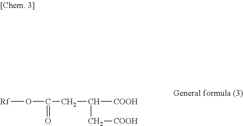
(In the expression, Rf is an unsubstituted or substituted and saturated or unsaturated fluorine-containing hydrocarbon group or hydrocarbon group.)

(In the general formula (4), 1 is an integer selected from the range of 8 to 30, more desirably 12 to 20.)

(In the general formula (5), m and n are integers respectively selected from the following ranges: m=2 to 20 and n=3 to 18, more desirably m=4 to 13 and n=3 to 10.)
(In the general formula (6), n1+n2=n and m1+m2=m hold.)
- CF3(CF2)7(CH2)10COOCH(COOH)CH2COOH
- CF3(CF2)3(CH2)10COOCH(COOH)CH2COOH
- C17H35COOCH(COOH)CH2COOH
- CF3(CF2)7(CH2)2OCOCH2CH(C18H37)COOCH(COOH)CH2COOH
- CF3(CF2)7COOCH(COOH)CH2COOH
- CHF2(CF2)7COOCH(COOH)CH2COOH
- CF3(CF2)7(CH2)2OCOCH2CH(COOH)CH2COOH
- CF3(CF2)7(CH2)6OCOCH2CH(COOH)CH2COOH
- CF3(CF2)7(CH2)11OCOCH2CH(COOH)CH2COOH
- CF3(CF2)3(CH2)6OCOCH2CH(COOH)CH2COOH
- C18H37OCOCH2CH(COOH)CH2COOH
- CF3(CF2)7(CH2)4COOCH(COOH)CH2COOH
- CF3(CF2)3(CH2)4COOCH(COOH)CH2COOH
- CF3(CF2)3(CH2)7COOCH(COOH)CH2COOH
- CF3(CF2)9(CH2)10COOCH(COOH)CH2COOH
- CF3(CF2)7(CH2)12COOCH(COOH)CH2COOH
- CF3(CF2)5(CH2)10COOCH(COOH)CH2COOH
- CF3(CF2)7CH(C9H19)CH2CH═CH(CH2)7COOCH(COOH)CH2COOH
- CF3(CF2)7CH(C6H13)(CH2)7COOCH(COOH)CH2COOH
- CH3(CH2)3(CH2CH2CH(CH2CH2(CF2)9CF3))2(CH2)7COOCH(COOH)CH2COOH.
(Number of Projections Having Height of 7.5 nm or More)
Threshold(7.5) (nm)=Ave surface(nm)+7.5 (nm) (3)
Threshold(5) (nm)=Ave_surface(nm)+5 (nm) (4)
Threshold(10) (nm)=Ave_surface (nm)+10 (nm) (5)
Threshold(15) (nm)=Ave_surface(nm)+15 (nm) (6)
Threshold(20) (nm)=Ave_surface(nm)+20 (nm) (7)
(Evaluation of Recording and Reproducing Properties)
| TABLE 1 | |
| Presence/absence of correlation | |
| Number of projections- | ||
| Height of | recording and reproducing | Number of projections- |
| projections | properties | high- |
| 5 nm or more | absent | absent |
| 7.5 nm or more | absent | present |
| 10 nm or more | absent | absent |
| 15 nm or more | present | absent |
| 20 nm or more | absent | absent |
| TABLE 2 | ||||
| Recording surface | Recording | |||
| Presence/ | and | ||||||
| Type of | absence | Peak | Peak | reproducing | Frictional | ||
| base | of uneven | SRa | (15) | (7.5) | properites | force | |
| substance | layer | [nm] | [number] | [number ] | [dB] | [%] | |
| Example 1 | Film A | Absent | 1.8 | 24 | 670 | 2.9 | 37 |
| Example 2 | Film A | Absent | 1.7 | 14 | 510 | 3.6 | 33 |
| Example 3 | Film A | Absent | 1.7 | 4 | 310 | 4.2 | 37 |
| Example 4 | Film A | Absent | 1.7 | 2 | 320 | 4.7 | 40 |
| Example 5 | Film B | Absent | 1.6 | 27 | 330 | 2.7 | 45 |
| Example 6 | Film B | Absent | 1.5 | 24 | 450 | 2.7 | 43 |
| Example 7 | Film B | Absent | 1.4 | 11 | 320 | 3.7 | 47 |
| Example 8 | Film B | Absent | 1.4 | 8 | 340 | 4.3 | 57 |
| Example 9 | Film B | Absent | 2.8 | 76 | 2540 | 1.4 | 12 |
| Example 10 | Film B | Present | 2.1 | 0 | 670 | 4.5 | 60 |
| Example 11 | Film B | Present | 2.9 | 79 | 2310 | 1.2 | 12 |
| Example 12 | Film B | Absent | 1.6 | 2 | 310 | 3.0 | 35 |
| Comparative | Film B | Absent | 1.5 | 105 | 255 | 0.0 | 100 |
| Example 1 | |||||||
| Comparative | Film B | Absent | 1.4 | 2 | 120 | 4.2 | 700 |
| Example 2 | |||||||
| Comparative | Film B | Absent | 1.4 | 2 | 110 | 4.6 | 380 |
| Example 3 | |||||||
| Comparative | Film B | Absent | 1.4 | 3 | 220 | 4.2 | 550 |
| Example 4 | |||||||
| Comparative | Film B | Absent | 1.5 | 0 | 130 | 5.0 | 117 |
| Example 5 | |||||||
| Comparative | Film B | Present | 2.3 | 150 | 1410 | −1.6 | 13 |
| Example 6 | |||||||
| Comparative | Film B | Present | 3.2 | 99 | 2800 | −1.5 | 11 |
| Example 7 | |||||||
-
- a foundation layer, and
- a seed layer provided between the foundation layer and the base substance.
(11)
(CoxPtyCr100-x-y)100-z-(SiO2)z
(where x, y, and z are values in the range of 69≤x≤72, 12≤y≤16, and 9≤z≤12, respectively).
- 11 base substance
- 12, 12A, 12B, 40 crystal control layer
- 13 magnetic layer
- 14 protective layer
- 15 lubricant layer
- 16 backcoat layer
- 17 uneven layer
- 18, 21, 41 seed layer
- 19 SUL
- 19A APC-SUL
- 19 a, 19 c soft magnetic layer
- 19 b, 42 intermediate layer
- 22 foundation layer
- 31 film formation chamber
- 32 drum
- 33 a, 33 b, 33 c cathodes
- 34 supply reel
- 35 take-up reel
Claims (21)
(CoxPtyCr100-x-y)100-z—(SiO2)z
Applications Claiming Priority (3)
| Application Number | Priority Date | Filing Date | Title |
|---|---|---|---|
| JP2015100859 | 2015-05-18 | ||
| JP2015-100859 | 2015-05-18 | ||
| PCT/JP2016/002337 WO2016185695A1 (en) | 2015-05-18 | 2016-05-12 | Magnetic recording medium |
Publications (2)
| Publication Number | Publication Date |
|---|---|
| US20180137887A1 US20180137887A1 (en) | 2018-05-17 |
| US10580447B2 true US10580447B2 (en) | 2020-03-03 |
Family
ID=57319797
Family Applications (1)
| Application Number | Title | Priority Date | Filing Date |
|---|---|---|---|
| US15/573,374 Active 2036-10-29 US10580447B2 (en) | 2015-05-18 | 2016-05-12 | Magnetic recording medium with controlled surface characteristics |
Country Status (4)
| Country | Link |
|---|---|
| US (1) | US10580447B2 (en) |
| EP (1) | EP3300080B1 (en) |
| JP (1) | JP6597775B2 (en) |
| WO (1) | WO2016185695A1 (en) |
Cited By (2)
| Publication number | Priority date | Publication date | Assignee | Title |
|---|---|---|---|---|
| US11437066B2 (en) * | 2018-03-30 | 2022-09-06 | Sony Corporation | Magnetic recording tape and magnetic recording tape cartridge |
| US11621020B2 (en) * | 2017-04-07 | 2023-04-04 | Sony Corporation | Magnetic recording medium |
Families Citing this family (89)
| Publication number | Priority date | Publication date | Assignee | Title |
|---|---|---|---|---|
| JP6316248B2 (en) | 2015-08-21 | 2018-04-25 | 富士フイルム株式会社 | Magnetic tape and manufacturing method thereof |
| US10540996B2 (en) | 2015-09-30 | 2020-01-21 | Fujifilm Corporation | Magnetic tape having characterized magnetic layer and magnetic tape device |
| DE112016005258T5 (en) * | 2015-11-17 | 2018-08-16 | Sony Corporation | Magnetic recording medium |
| US10403319B2 (en) | 2015-12-16 | 2019-09-03 | Fujifilm Corporation | Magnetic tape having characterized magnetic layer, tape cartridge, and recording and reproducing device |
| JP6552402B2 (en) | 2015-12-16 | 2019-07-31 | 富士フイルム株式会社 | Magnetic tape, magnetic tape cartridge, magnetic recording / reproducing apparatus, and method of manufacturing magnetic tape |
| JP6430927B2 (en) | 2015-12-25 | 2018-11-28 | 富士フイルム株式会社 | Magnetic tape and manufacturing method thereof |
| JP6465823B2 (en) | 2016-02-03 | 2019-02-06 | 富士フイルム株式会社 | Magnetic tape and manufacturing method thereof |
| JP6427127B2 (en) | 2016-02-03 | 2018-11-21 | 富士フイルム株式会社 | Magnetic tape and method of manufacturing the same |
| JP6472764B2 (en) | 2016-02-29 | 2019-02-20 | 富士フイルム株式会社 | Magnetic tape |
| JP6474748B2 (en) | 2016-02-29 | 2019-02-27 | 富士フイルム株式会社 | Magnetic tape |
| JP6467366B2 (en) | 2016-02-29 | 2019-02-13 | 富士フイルム株式会社 | Magnetic tape |
| JP6556096B2 (en) | 2016-06-10 | 2019-08-07 | 富士フイルム株式会社 | Magnetic tape and magnetic tape device |
| JP6534637B2 (en) | 2016-06-13 | 2019-06-26 | 富士フイルム株式会社 | Magnetic tape and magnetic tape device |
| JP6534969B2 (en) | 2016-06-22 | 2019-06-26 | 富士フイルム株式会社 | Magnetic tape |
| JP6556100B2 (en) | 2016-06-22 | 2019-08-07 | 富士フイルム株式会社 | Magnetic tape |
| JP6549529B2 (en) | 2016-06-23 | 2019-07-24 | 富士フイルム株式会社 | Magnetic tape and magnetic tape device |
| JP6717684B2 (en) | 2016-06-23 | 2020-07-01 | 富士フイルム株式会社 | Magnetic tape and magnetic tape device |
| JP6496277B2 (en) | 2016-06-23 | 2019-04-03 | 富士フイルム株式会社 | Magnetic tape |
| JP6498154B2 (en) | 2016-06-23 | 2019-04-10 | 富士フイルム株式会社 | Magnetic tape and magnetic tape device |
| JP6556102B2 (en) | 2016-06-23 | 2019-08-07 | 富士フイルム株式会社 | Magnetic tape and magnetic tape device |
| JP6549528B2 (en) | 2016-06-23 | 2019-07-24 | 富士フイルム株式会社 | Magnetic tape and magnetic tape device |
| JP6507126B2 (en) | 2016-06-23 | 2019-04-24 | 富士フイルム株式会社 | Magnetic tape and magnetic tape device |
| JP6556101B2 (en) | 2016-06-23 | 2019-08-07 | 富士フイルム株式会社 | Magnetic tape and magnetic tape device |
| JP6529933B2 (en) | 2016-06-24 | 2019-06-12 | 富士フイルム株式会社 | Magnetic tape |
| JP6556107B2 (en) | 2016-08-31 | 2019-08-07 | 富士フイルム株式会社 | Magnetic tape |
| JP6552467B2 (en) | 2016-08-31 | 2019-07-31 | 富士フイルム株式会社 | Magnetic tape |
| JP6585570B2 (en) | 2016-09-16 | 2019-10-02 | 富士フイルム株式会社 | Magnetic recording medium and method for manufacturing the same |
| JP2018106778A (en) | 2016-12-27 | 2018-07-05 | 富士フイルム株式会社 | Magnetic tape device and magnetic reproducing method |
| JP6684203B2 (en) | 2016-12-27 | 2020-04-22 | 富士フイルム株式会社 | Magnetic tape device and magnetic reproducing method |
| JP6588002B2 (en) | 2016-12-27 | 2019-10-09 | 富士フイルム株式会社 | Magnetic tape device and magnetic reproducing method |
| JP6701072B2 (en) | 2016-12-27 | 2020-05-27 | 富士フイルム株式会社 | Magnetic tape device and head tracking servo method |
| JP6689222B2 (en) | 2017-02-20 | 2020-04-28 | 富士フイルム株式会社 | Magnetic tape |
| JP6649297B2 (en) | 2017-02-20 | 2020-02-19 | 富士フイルム株式会社 | Magnetic tape device and magnetic reproducing method |
| JP6684237B2 (en) | 2017-02-20 | 2020-04-22 | 富士フイルム株式会社 | Magnetic tape device and head tracking servo method |
| JP6684235B2 (en) * | 2017-02-20 | 2020-04-22 | 富士フイルム株式会社 | Magnetic tape device and head tracking servo method |
| JP6684238B2 (en) | 2017-02-20 | 2020-04-22 | 富士フイルム株式会社 | Magnetic tape |
| JP6684234B2 (en) * | 2017-02-20 | 2020-04-22 | 富士フイルム株式会社 | Magnetic tape device and magnetic reproducing method |
| JP6684236B2 (en) * | 2017-02-20 | 2020-04-22 | 富士フイルム株式会社 | Magnetic tape device and magnetic reproducing method |
| JP6637456B2 (en) | 2017-02-20 | 2020-01-29 | 富士フイルム株式会社 | Magnetic tape |
| JP6649298B2 (en) | 2017-02-20 | 2020-02-19 | 富士フイルム株式会社 | Magnetic tape device and head tracking servo method |
| JP6602805B2 (en) | 2017-02-20 | 2019-11-06 | 富士フイルム株式会社 | Magnetic tape |
| JP6685248B2 (en) | 2017-02-20 | 2020-04-22 | 富士フイルム株式会社 | Magnetic tape |
| JP6689223B2 (en) | 2017-02-20 | 2020-04-28 | 富士フイルム株式会社 | Magnetic tape |
| JP6602806B2 (en) | 2017-02-20 | 2019-11-06 | 富士フイルム株式会社 | Magnetic tape |
| JP6684239B2 (en) | 2017-02-20 | 2020-04-22 | 富士フイルム株式会社 | Magnetic tape |
| JP6626032B2 (en) | 2017-03-29 | 2019-12-25 | 富士フイルム株式会社 | Magnetic tape device and magnetic reproducing method |
| JP6649312B2 (en) | 2017-03-29 | 2020-02-19 | 富士フイルム株式会社 | Magnetic tape device and magnetic reproducing method |
| JP6660336B2 (en) | 2017-03-29 | 2020-03-11 | 富士フイルム株式会社 | Magnetic tape device and head tracking servo method |
| JP6626031B2 (en) | 2017-03-29 | 2019-12-25 | 富士フイルム株式会社 | Magnetic tape device and magnetic reproducing method |
| JP6615814B2 (en) | 2017-03-29 | 2019-12-04 | 富士フイルム株式会社 | Magnetic tape device and head tracking servo method |
| JP6649314B2 (en) | 2017-03-29 | 2020-02-19 | 富士フイルム株式会社 | Magnetic tape device and head tracking servo method |
| JP6632561B2 (en) | 2017-03-29 | 2020-01-22 | 富士フイルム株式会社 | Magnetic tape device and magnetic reproducing method |
| JP6694844B2 (en) | 2017-03-29 | 2020-05-20 | 富士フイルム株式会社 | Magnetic tape device, magnetic reproducing method and head tracking servo method |
| JP6615815B2 (en) | 2017-03-29 | 2019-12-04 | 富士フイルム株式会社 | Magnetic tape device and head tracking servo method |
| JP6632562B2 (en) | 2017-03-29 | 2020-01-22 | 富士フイルム株式会社 | Magnetic tape |
| JP6649313B2 (en) | 2017-03-29 | 2020-02-19 | 富士フイルム株式会社 | Magnetic tape device and magnetic reproducing method |
| JP6691512B2 (en) | 2017-06-23 | 2020-04-28 | 富士フイルム株式会社 | Magnetic recording medium |
| JP6723198B2 (en) | 2017-06-23 | 2020-07-15 | 富士フイルム株式会社 | Magnetic tape and magnetic tape device |
| JP6714548B2 (en) | 2017-07-19 | 2020-06-24 | 富士フイルム株式会社 | Magnetic tape and magnetic tape device |
| US10854227B2 (en) | 2017-07-19 | 2020-12-01 | Fujifilm Corporation | Magnetic recording medium having characterized magnetic layer |
| JP6707060B2 (en) | 2017-07-19 | 2020-06-10 | 富士フイルム株式会社 | Magnetic tape |
| JP6723203B2 (en) | 2017-07-19 | 2020-07-15 | 富士フイルム株式会社 | Magnetic tape |
| US10839849B2 (en) | 2017-07-19 | 2020-11-17 | Fujifilm Corporation | Magnetic recording medium having characterized magnetic layer |
| JP6678135B2 (en) | 2017-07-19 | 2020-04-08 | 富士フイルム株式会社 | Magnetic recording media |
| JP6707061B2 (en) | 2017-07-19 | 2020-06-10 | 富士フイルム株式会社 | Magnetic recording medium |
| JP6717787B2 (en) | 2017-07-19 | 2020-07-08 | 富士フイルム株式会社 | Magnetic tape and magnetic tape device |
| JP6717786B2 (en) | 2017-07-19 | 2020-07-08 | 富士フイルム株式会社 | Magnetic tape and magnetic tape device |
| US10854230B2 (en) | 2017-07-19 | 2020-12-01 | Fujifilm Corporation | Magnetic tape having characterized magnetic layer |
| JP6723202B2 (en) | 2017-07-19 | 2020-07-15 | 富士フイルム株式会社 | Magnetic tape |
| JP6717785B2 (en) | 2017-07-19 | 2020-07-08 | 富士フイルム株式会社 | Magnetic recording medium |
| WO2019065200A1 (en) | 2017-09-29 | 2019-04-04 | 富士フイルム株式会社 | Magnetic tape and magnetic recording/reproducing apparatus |
| US10854233B2 (en) | 2017-09-29 | 2020-12-01 | Fujifilm Corporation | Magnetic recording medium having characterized magnetic layer and magnetic recording and reproducing device |
| US10854231B2 (en) | 2017-09-29 | 2020-12-01 | Fujifilm Corporation | Magnetic recording medium having characterized magnetic layer and magnetic recording and reproducing device |
| US10854234B2 (en) | 2017-09-29 | 2020-12-01 | Fujifilm Corporation | Magnetic recording medium having characterized magnetic layer and magnetic recording and reproducing device |
| US10515657B2 (en) | 2017-09-29 | 2019-12-24 | Fujifilm Corporation | Magnetic tape having characterized magnetic layer and magnetic recording and reproducing device |
| CN111164685B (en) | 2017-09-29 | 2021-07-23 | 富士胶片株式会社 | Magnetic tape and magnetic recording/reproducing apparatus |
| US10978105B2 (en) | 2017-09-29 | 2021-04-13 | Fujifilm Corporation | Magnetic recording medium having characterized magnetic layer and magnetic recording and reproducing device |
| US11361793B2 (en) | 2018-03-23 | 2022-06-14 | Fujifilm Corporation | Magnetic tape having characterized magnetic layer and magnetic recording and reproducing device |
| US11361792B2 (en) | 2018-03-23 | 2022-06-14 | Fujifilm Corporation | Magnetic tape having characterized magnetic layer and magnetic recording and reproducing device |
| US11514943B2 (en) | 2018-03-23 | 2022-11-29 | Fujifilm Corporation | Magnetic tape and magnetic tape device |
| US11514944B2 (en) | 2018-03-23 | 2022-11-29 | Fujifilm Corporation | Magnetic tape and magnetic tape device |
| JP6830931B2 (en) | 2018-07-27 | 2021-02-17 | 富士フイルム株式会社 | Magnetic tapes, magnetic tape cartridges and magnetic tape devices |
| JP6784738B2 (en) | 2018-10-22 | 2020-11-11 | 富士フイルム株式会社 | Magnetic tapes, magnetic tape cartridges and magnetic tape devices |
| JP6830945B2 (en) | 2018-12-28 | 2021-02-17 | 富士フイルム株式会社 | Magnetic tapes, magnetic tape cartridges and magnetic tape devices |
| JP7042737B2 (en) | 2018-12-28 | 2022-03-28 | 富士フイルム株式会社 | Magnetic tape, magnetic tape cartridge and magnetic tape device |
| JP7003073B2 (en) | 2019-01-31 | 2022-01-20 | 富士フイルム株式会社 | Magnetic tapes, magnetic tape cartridges and magnetic tape devices |
| JP6590102B1 (en) * | 2019-04-26 | 2019-10-16 | ソニー株式会社 | Magnetic recording cartridge |
| JP6778804B1 (en) | 2019-09-17 | 2020-11-04 | 富士フイルム株式会社 | Magnetic recording medium and magnetic recording / playback device |
| US11854585B2 (en) * | 2020-01-21 | 2023-12-26 | Sony Group Corporation | Magnetic recording medium and cartridge |
Citations (13)
| Publication number | Priority date | Publication date | Assignee | Title |
|---|---|---|---|---|
| US6251496B1 (en) * | 1997-12-16 | 2001-06-26 | Matsushita Electric Industrial Co., Ltd. | Magnetic recording medium method and apparatus for producing the same |
| US6372367B1 (en) * | 1998-05-12 | 2002-04-16 | Hitachi, Ltd. | Magnetic recording medium, method for producing the same and magnetic recording apparatus using the same |
| US6395412B1 (en) * | 1999-05-24 | 2002-05-28 | Hitachi, Ltd. | Magnetic recording media, manufacturing method for thereof and apparatus for using the media |
| US6468628B2 (en) * | 2000-01-18 | 2002-10-22 | Toray Industries, Inc. | Magnetic recording medium |
| US6652953B2 (en) * | 1998-07-22 | 2003-11-25 | Fuji Photo Film Co., Ltd. | Magnetic recording medium |
| JP2005196885A (en) | 2004-01-08 | 2005-07-21 | Sony Corp | Magnetic recording medium |
| JP2005293787A (en) | 2004-04-05 | 2005-10-20 | Fuji Photo Film Co Ltd | Magnetic recording medium |
| US7026064B1 (en) * | 2000-03-07 | 2006-04-11 | Toray Industries, Inc. | Polyester film and method for producing the same |
| US20060088735A1 (en) * | 2004-10-27 | 2006-04-27 | Hitachi Global Storage Technologies Netherlands B.V. | Method for manufacturing magnetic disk using cleaning tape |
| US20070042227A1 (en) * | 2003-09-25 | 2007-02-22 | Takeshi Iwasaki | Perpendicular magnetic recording medium and magnetic recording/reproducing apparatus |
| JP2007250059A (en) | 2006-03-15 | 2007-09-27 | Fuji Electric Device Technology Co Ltd | Magnetic recording medium and manufacturing method thereof |
| US20080020243A1 (en) * | 2006-06-30 | 2008-01-24 | Fujifilm Corporation | Carbonic acid ester, production process therefor, and magnetic recording medium |
| US20130314815A1 (en) * | 2012-05-23 | 2013-11-28 | Wd Media, Inc. | Underlayers for heat assisted magnetic recording (hamr) media |
Family Cites Families (7)
| Publication number | Priority date | Publication date | Assignee | Title |
|---|---|---|---|---|
| DE69411476T2 (en) * | 1993-09-06 | 1999-02-25 | Matsushita Electric Ind Co Ltd | Magnetic record carrier |
| JP2002216340A (en) * | 2000-06-22 | 2002-08-02 | Sony Corp | Magnetic recording medium |
| SG108872A1 (en) * | 2001-10-24 | 2005-02-28 | Toda Kogyo Corp | Perpendicular magnetic recording medium |
| SG118182A1 (en) * | 2002-03-19 | 2006-01-27 | Fuji Electric Co Ltd | Method for producing a magnetic recording medium and a magnetic recording medium produced by the method |
| JP2003317232A (en) * | 2002-04-19 | 2003-11-07 | Fuji Photo Film Co Ltd | Magnetic recording medium |
| JP4540288B2 (en) * | 2002-06-17 | 2010-09-08 | 富士電機デバイステクノロジー株式会社 | Perpendicular magnetic recording medium and manufacturing method thereof |
| JP6307879B2 (en) * | 2013-05-17 | 2018-04-11 | ソニー株式会社 | Magnetic recording medium and method for manufacturing the same |
-
2016
- 2016-05-12 US US15/573,374 patent/US10580447B2/en active Active
- 2016-05-12 JP JP2017518752A patent/JP6597775B2/en active Active
- 2016-05-12 EP EP16796091.3A patent/EP3300080B1/en active Active
- 2016-05-12 WO PCT/JP2016/002337 patent/WO2016185695A1/en active Application Filing
Patent Citations (13)
| Publication number | Priority date | Publication date | Assignee | Title |
|---|---|---|---|---|
| US6251496B1 (en) * | 1997-12-16 | 2001-06-26 | Matsushita Electric Industrial Co., Ltd. | Magnetic recording medium method and apparatus for producing the same |
| US6372367B1 (en) * | 1998-05-12 | 2002-04-16 | Hitachi, Ltd. | Magnetic recording medium, method for producing the same and magnetic recording apparatus using the same |
| US6652953B2 (en) * | 1998-07-22 | 2003-11-25 | Fuji Photo Film Co., Ltd. | Magnetic recording medium |
| US6395412B1 (en) * | 1999-05-24 | 2002-05-28 | Hitachi, Ltd. | Magnetic recording media, manufacturing method for thereof and apparatus for using the media |
| US6468628B2 (en) * | 2000-01-18 | 2002-10-22 | Toray Industries, Inc. | Magnetic recording medium |
| US7026064B1 (en) * | 2000-03-07 | 2006-04-11 | Toray Industries, Inc. | Polyester film and method for producing the same |
| US20070042227A1 (en) * | 2003-09-25 | 2007-02-22 | Takeshi Iwasaki | Perpendicular magnetic recording medium and magnetic recording/reproducing apparatus |
| JP2005196885A (en) | 2004-01-08 | 2005-07-21 | Sony Corp | Magnetic recording medium |
| JP2005293787A (en) | 2004-04-05 | 2005-10-20 | Fuji Photo Film Co Ltd | Magnetic recording medium |
| US20060088735A1 (en) * | 2004-10-27 | 2006-04-27 | Hitachi Global Storage Technologies Netherlands B.V. | Method for manufacturing magnetic disk using cleaning tape |
| JP2007250059A (en) | 2006-03-15 | 2007-09-27 | Fuji Electric Device Technology Co Ltd | Magnetic recording medium and manufacturing method thereof |
| US20080020243A1 (en) * | 2006-06-30 | 2008-01-24 | Fujifilm Corporation | Carbonic acid ester, production process therefor, and magnetic recording medium |
| US20130314815A1 (en) * | 2012-05-23 | 2013-11-28 | Wd Media, Inc. | Underlayers for heat assisted magnetic recording (hamr) media |
Non-Patent Citations (2)
| Title |
|---|
| International Search Report (with English translation) dated Aug. 2, 2016 in corresponding international application No. 002337 (5 pages). |
| Written Opinion dated Aug. 2, 2016 in corresponding international application No. PCT/JP2016/002337 (6 pages). |
Cited By (2)
| Publication number | Priority date | Publication date | Assignee | Title |
|---|---|---|---|---|
| US11621020B2 (en) * | 2017-04-07 | 2023-04-04 | Sony Corporation | Magnetic recording medium |
| US11437066B2 (en) * | 2018-03-30 | 2022-09-06 | Sony Corporation | Magnetic recording tape and magnetic recording tape cartridge |
Also Published As
| Publication number | Publication date |
|---|---|
| WO2016185695A1 (en) | 2016-11-24 |
| EP3300080A4 (en) | 2018-10-03 |
| JPWO2016185695A1 (en) | 2018-03-08 |
| EP3300080B1 (en) | 2020-02-05 |
| JP6597775B2 (en) | 2019-10-30 |
| US20180137887A1 (en) | 2018-05-17 |
| EP3300080A1 (en) | 2018-03-28 |
Similar Documents
| Publication | Publication Date | Title |
|---|---|---|
| US10580447B2 (en) | Magnetic recording medium with controlled surface characteristics | |
| JP6590102B1 (en) | Magnetic recording cartridge | |
| JP6753548B1 (en) | Magnetic recording medium and cartridge | |
| JP6590103B1 (en) | Magnetic recording medium | |
| JP6610823B1 (en) | Magnetic recording medium | |
| US11315594B2 (en) | Magnetic recording medium having controlled dimensional variation | |
| JP6610822B1 (en) | Magnetic recording medium | |
| US20200342901A1 (en) | Magnetic recording medium | |
| JP6662488B1 (en) | Magnetic recording cartridge | |
| JP6733798B1 (en) | Magnetic recording medium | |
| JP6662487B1 (en) | Magnetic recording media | |
| JP6677340B1 (en) | Magnetic recording media | |
| JP6677339B1 (en) | Magnetic recording media | |
| JP2020166925A (en) | Magnetic recording medium | |
| JP2020166919A (en) | Magnetic recording medium |
Legal Events
| Date | Code | Title | Description |
|---|---|---|---|
| FEPP | Fee payment procedure |
Free format text: ENTITY STATUS SET TO UNDISCOUNTED (ORIGINAL EVENT CODE: BIG.); ENTITY STATUS OF PATENT OWNER: LARGE ENTITY |
|
| STPP | Information on status: patent application and granting procedure in general |
Free format text: DOCKETED NEW CASE - READY FOR EXAMINATION |
|
| STPP | Information on status: patent application and granting procedure in general |
Free format text: NON FINAL ACTION MAILED |
|
| STPP | Information on status: patent application and granting procedure in general |
Free format text: RESPONSE TO NON-FINAL OFFICE ACTION ENTERED AND FORWARDED TO EXAMINER |
|
| STPP | Information on status: patent application and granting procedure in general |
Free format text: NOTICE OF ALLOWANCE MAILED -- APPLICATION RECEIVED IN OFFICE OF PUBLICATIONS |
|
| AS | Assignment |
Owner name: SONY CORPORATION, JAPAN Free format text: ASSIGNMENT OF ASSIGNORS INTEREST;ASSIGNORS:SEKIGUCHI, NOBORU;OZAKI, TOMOE;ENDO, TETSUO;AND OTHERS;SIGNING DATES FROM 20170919 TO 20170920;REEL/FRAME:050870/0618 |
|
| STPP | Information on status: patent application and granting procedure in general |
Free format text: PUBLICATIONS -- ISSUE FEE PAYMENT VERIFIED |
|
| STCF | Information on status: patent grant |
Free format text: PATENTED CASE |
|
| MAFP | Maintenance fee payment |
Free format text: PAYMENT OF MAINTENANCE FEE, 4TH YEAR, LARGE ENTITY (ORIGINAL EVENT CODE: M1551); ENTITY STATUS OF PATENT OWNER: LARGE ENTITY Year of fee payment: 4 |