JP6083389B2 - Magnetic recording medium - Google Patents
Magnetic recording medium Download PDFInfo
- Publication number
- JP6083389B2 JP6083389B2 JP2014001233A JP2014001233A JP6083389B2 JP 6083389 B2 JP6083389 B2 JP 6083389B2 JP 2014001233 A JP2014001233 A JP 2014001233A JP 2014001233 A JP2014001233 A JP 2014001233A JP 6083389 B2 JP6083389 B2 JP 6083389B2
- Authority
- JP
- Japan
- Prior art keywords
- layer
- psd
- magnetic recording
- recording medium
- medium according
- Prior art date
- Legal status (The legal status is an assumption and is not a legal conclusion. Google has not performed a legal analysis and makes no representation as to the accuracy of the status listed.)
- Active
Links
- 230000005291 magnetic effect Effects 0.000 title claims description 258
- 239000000758 substrate Substances 0.000 claims description 51
- 238000004544 sputter deposition Methods 0.000 claims description 34
- 229910052804 chromium Inorganic materials 0.000 claims description 32
- 229910052719 titanium Inorganic materials 0.000 claims description 25
- 229910052760 oxygen Inorganic materials 0.000 claims description 16
- 229910004298 SiO 2 Inorganic materials 0.000 claims description 12
- 238000009751 slip forming Methods 0.000 claims description 11
- 238000005096 rolling process Methods 0.000 claims description 10
- 239000000203 mixture Substances 0.000 claims description 9
- 229910052697 platinum Inorganic materials 0.000 claims description 6
- 239000002245 particle Substances 0.000 claims description 4
- 239000002952 polymeric resin Substances 0.000 claims description 3
- 229920003002 synthetic resin Polymers 0.000 claims description 2
- 239000010410 layer Substances 0.000 description 311
- 239000010408 film Substances 0.000 description 68
- 238000000034 method Methods 0.000 description 43
- 239000000463 material Substances 0.000 description 26
- 238000005516 engineering process Methods 0.000 description 23
- 229910045601 alloy Inorganic materials 0.000 description 20
- 239000000956 alloy Substances 0.000 description 20
- 239000013078 crystal Substances 0.000 description 20
- 239000007789 gas Substances 0.000 description 20
- 230000015572 biosynthetic process Effects 0.000 description 19
- 230000000052 comparative effect Effects 0.000 description 19
- 239000011241 protective layer Substances 0.000 description 16
- 239000002356 single layer Substances 0.000 description 14
- 230000008569 process Effects 0.000 description 13
- 230000000694 effects Effects 0.000 description 12
- 238000001755 magnetron sputter deposition Methods 0.000 description 12
- 229910044991 metal oxide Inorganic materials 0.000 description 11
- 230000005415 magnetization Effects 0.000 description 10
- 238000005259 measurement Methods 0.000 description 9
- 150000004706 metal oxides Chemical class 0.000 description 9
- 239000000314 lubricant Substances 0.000 description 8
- 239000001301 oxygen Substances 0.000 description 8
- 229920006254 polymer film Polymers 0.000 description 8
- QVGXLLKOCUKJST-UHFFFAOYSA-N atomic oxygen Chemical compound [O] QVGXLLKOCUKJST-UHFFFAOYSA-N 0.000 description 7
- 238000005137 deposition process Methods 0.000 description 7
- 238000011156 evaluation Methods 0.000 description 7
- 230000004048 modification Effects 0.000 description 7
- 238000012986 modification Methods 0.000 description 7
- 229910010169 TiCr Inorganic materials 0.000 description 6
- 238000000151 deposition Methods 0.000 description 6
- 230000008021 deposition Effects 0.000 description 6
- 239000000696 magnetic material Substances 0.000 description 6
- 238000004519 manufacturing process Methods 0.000 description 6
- 239000002184 metal Substances 0.000 description 6
- 229910052751 metal Inorganic materials 0.000 description 6
- 229910010413 TiO 2 Inorganic materials 0.000 description 5
- 239000013074 reference sample Substances 0.000 description 5
- 238000001228 spectrum Methods 0.000 description 5
- OKTJSMMVPCPJKN-UHFFFAOYSA-N Carbon Chemical compound [C] OKTJSMMVPCPJKN-UHFFFAOYSA-N 0.000 description 4
- 239000000654 additive Substances 0.000 description 4
- 230000000996 additive effect Effects 0.000 description 4
- 230000005294 ferromagnetic effect Effects 0.000 description 4
- 150000004767 nitrides Chemical class 0.000 description 4
- 229910052710 silicon Inorganic materials 0.000 description 4
- 238000004804 winding Methods 0.000 description 4
- 229910000929 Ru alloy Inorganic materials 0.000 description 3
- 230000009471 action Effects 0.000 description 3
- 229910052782 aluminium Inorganic materials 0.000 description 3
- 229910052799 carbon Inorganic materials 0.000 description 3
- 239000003575 carbonaceous material Substances 0.000 description 3
- 230000007423 decrease Effects 0.000 description 3
- 239000012535 impurity Substances 0.000 description 3
- 230000002093 peripheral effect Effects 0.000 description 3
- 230000003595 spectral effect Effects 0.000 description 3
- 238000003860 storage Methods 0.000 description 3
- 229910052715 tantalum Inorganic materials 0.000 description 3
- 239000010409 thin film Substances 0.000 description 3
- 238000012935 Averaging Methods 0.000 description 2
- 239000004215 Carbon black (E152) Substances 0.000 description 2
- 229910052684 Cerium Inorganic materials 0.000 description 2
- CPLXHLVBOLITMK-UHFFFAOYSA-N Magnesium oxide Chemical compound [Mg]=O CPLXHLVBOLITMK-UHFFFAOYSA-N 0.000 description 2
- VYPSYNLAJGMNEJ-UHFFFAOYSA-N Silicium dioxide Chemical compound O=[Si]=O VYPSYNLAJGMNEJ-UHFFFAOYSA-N 0.000 description 2
- 230000008859 change Effects 0.000 description 2
- 238000005229 chemical vapour deposition Methods 0.000 description 2
- NEHMKBQYUWJMIP-UHFFFAOYSA-N chloromethane Chemical compound ClC NEHMKBQYUWJMIP-UHFFFAOYSA-N 0.000 description 2
- 230000008878 coupling Effects 0.000 description 2
- 238000010168 coupling process Methods 0.000 description 2
- 238000005859 coupling reaction Methods 0.000 description 2
- 238000010586 diagram Methods 0.000 description 2
- 238000005530 etching Methods 0.000 description 2
- 238000001914 filtration Methods 0.000 description 2
- 229910052735 hafnium Inorganic materials 0.000 description 2
- 229930195733 hydrocarbon Natural products 0.000 description 2
- 150000002430 hydrocarbons Chemical class 0.000 description 2
- 238000010884 ion-beam technique Methods 0.000 description 2
- 239000007769 metal material Substances 0.000 description 2
- 229910052750 molybdenum Inorganic materials 0.000 description 2
- 229910052759 nickel Inorganic materials 0.000 description 2
- 238000005240 physical vapour deposition Methods 0.000 description 2
- 239000002861 polymer material Substances 0.000 description 2
- 230000009467 reduction Effects 0.000 description 2
- 239000000523 sample Substances 0.000 description 2
- 238000000682 scanning probe acoustic microscopy Methods 0.000 description 2
- 230000003746 surface roughness Effects 0.000 description 2
- 229910052727 yttrium Inorganic materials 0.000 description 2
- 229910052726 zirconium Inorganic materials 0.000 description 2
- 229910018072 Al 2 O 3 Inorganic materials 0.000 description 1
- 229910019586 CoZrTa Inorganic materials 0.000 description 1
- 239000004952 Polyamide Substances 0.000 description 1
- 239000004642 Polyimide Substances 0.000 description 1
- ATJFFYVFTNAWJD-UHFFFAOYSA-N Tin Chemical compound [Sn] ATJFFYVFTNAWJD-UHFFFAOYSA-N 0.000 description 1
- 229920002678 cellulose Polymers 0.000 description 1
- 239000001913 cellulose Substances 0.000 description 1
- IVMYJDGYRUAWML-UHFFFAOYSA-N cobalt(II) oxide Inorganic materials [Co]=O IVMYJDGYRUAWML-UHFFFAOYSA-N 0.000 description 1
- 238000001816 cooling Methods 0.000 description 1
- 229910052802 copper Inorganic materials 0.000 description 1
- 238000013500 data storage Methods 0.000 description 1
- 238000011161 development Methods 0.000 description 1
- 229910003460 diamond Inorganic materials 0.000 description 1
- 239000010432 diamond Substances 0.000 description 1
- 238000003618 dip coating Methods 0.000 description 1
- 238000002003 electron diffraction Methods 0.000 description 1
- 230000005496 eutectics Effects 0.000 description 1
- 229920005570 flexible polymer Polymers 0.000 description 1
- 230000004907 flux Effects 0.000 description 1
- 229910002804 graphite Inorganic materials 0.000 description 1
- 239000010439 graphite Substances 0.000 description 1
- 238000007756 gravure coating Methods 0.000 description 1
- 125000001475 halogen functional group Chemical group 0.000 description 1
- 230000003993 interaction Effects 0.000 description 1
- 229910000765 intermetallic Inorganic materials 0.000 description 1
- 230000007774 longterm Effects 0.000 description 1
- 230000005381 magnetic domain Effects 0.000 description 1
- 230000007246 mechanism Effects 0.000 description 1
- 229910052758 niobium Inorganic materials 0.000 description 1
- 230000006911 nucleation Effects 0.000 description 1
- 238000010899 nucleation Methods 0.000 description 1
- 150000002926 oxygen Chemical class 0.000 description 1
- 229920002647 polyamide Polymers 0.000 description 1
- 239000004417 polycarbonate Substances 0.000 description 1
- 229920000515 polycarbonate Polymers 0.000 description 1
- 229920000728 polyester Polymers 0.000 description 1
- 229920001721 polyimide Polymers 0.000 description 1
- 229920000098 polyolefin Polymers 0.000 description 1
- 229920001296 polysiloxane Polymers 0.000 description 1
- 230000002035 prolonged effect Effects 0.000 description 1
- 230000001737 promoting effect Effects 0.000 description 1
- 230000001681 protective effect Effects 0.000 description 1
- 229920005989 resin Polymers 0.000 description 1
- 239000011347 resin Substances 0.000 description 1
- 229910052702 rhenium Inorganic materials 0.000 description 1
- 229910052703 rhodium Inorganic materials 0.000 description 1
- 238000010079 rubber tapping Methods 0.000 description 1
- 229910052707 ruthenium Inorganic materials 0.000 description 1
- 238000005070 sampling Methods 0.000 description 1
- 239000000377 silicon dioxide Substances 0.000 description 1
- 235000012239 silicon dioxide Nutrition 0.000 description 1
- 239000006104 solid solution Substances 0.000 description 1
- 238000001179 sorption measurement Methods 0.000 description 1
- 230000001629 suppression Effects 0.000 description 1
- 239000002344 surface layer Substances 0.000 description 1
- 230000009466 transformation Effects 0.000 description 1
- 229910052721 tungsten Inorganic materials 0.000 description 1
- 229910052720 vanadium Inorganic materials 0.000 description 1
- 125000000391 vinyl group Chemical group [H]C([*])=C([H])[H] 0.000 description 1
- 229920002554 vinyl polymer Polymers 0.000 description 1
Images


Classifications
-
- G—PHYSICS
- G11—INFORMATION STORAGE
- G11B—INFORMATION STORAGE BASED ON RELATIVE MOVEMENT BETWEEN RECORD CARRIER AND TRANSDUCER
- G11B5/00—Recording by magnetisation or demagnetisation of a record carrier; Reproducing by magnetic means; Record carriers therefor
- G11B5/62—Record carriers characterised by the selection of the material
- G11B5/73—Base layers, i.e. all non-magnetic layers lying under a lowermost magnetic recording layer, e.g. including any non-magnetic layer in between a first magnetic recording layer and either an underlying substrate or a soft magnetic underlayer
- G11B5/7368—Non-polymeric layer under the lowermost magnetic recording layer
- G11B5/7369—Two or more non-magnetic underlayers, e.g. seed layers or barrier layers
-
- G—PHYSICS
- G11—INFORMATION STORAGE
- G11B—INFORMATION STORAGE BASED ON RELATIVE MOVEMENT BETWEEN RECORD CARRIER AND TRANSDUCER
- G11B5/00—Recording by magnetisation or demagnetisation of a record carrier; Reproducing by magnetic means; Record carriers therefor
- G11B5/62—Record carriers characterised by the selection of the material
- G11B5/64—Record carriers characterised by the selection of the material comprising only the magnetic material without bonding agent
- G11B5/65—Record carriers characterised by the selection of the material comprising only the magnetic material without bonding agent characterised by its composition
- G11B5/658—Record carriers characterised by the selection of the material comprising only the magnetic material without bonding agent characterised by its composition containing oxygen, e.g. molecular oxygen or magnetic oxide
-
- G—PHYSICS
- G11—INFORMATION STORAGE
- G11B—INFORMATION STORAGE BASED ON RELATIVE MOVEMENT BETWEEN RECORD CARRIER AND TRANSDUCER
- G11B5/00—Recording by magnetisation or demagnetisation of a record carrier; Reproducing by magnetic means; Record carriers therefor
- G11B5/62—Record carriers characterised by the selection of the material
- G11B5/64—Record carriers characterised by the selection of the material comprising only the magnetic material without bonding agent
- G11B5/66—Record carriers characterised by the selection of the material comprising only the magnetic material without bonding agent the record carriers consisting of several layers
- G11B5/667—Record carriers characterised by the selection of the material comprising only the magnetic material without bonding agent the record carriers consisting of several layers including a soft magnetic layer
-
- G—PHYSICS
- G11—INFORMATION STORAGE
- G11B—INFORMATION STORAGE BASED ON RELATIVE MOVEMENT BETWEEN RECORD CARRIER AND TRANSDUCER
- G11B5/00—Recording by magnetisation or demagnetisation of a record carrier; Reproducing by magnetic means; Record carriers therefor
- G11B5/62—Record carriers characterised by the selection of the material
- G11B5/64—Record carriers characterised by the selection of the material comprising only the magnetic material without bonding agent
- G11B5/66—Record carriers characterised by the selection of the material comprising only the magnetic material without bonding agent the record carriers consisting of several layers
- G11B5/676—Record carriers characterised by the selection of the material comprising only the magnetic material without bonding agent the record carriers consisting of several layers having magnetic layers separated by a nonmagnetic layer, e.g. antiferromagnetic layer, Cu layer or coupling layer
-
- G—PHYSICS
- G11—INFORMATION STORAGE
- G11B—INFORMATION STORAGE BASED ON RELATIVE MOVEMENT BETWEEN RECORD CARRIER AND TRANSDUCER
- G11B5/00—Recording by magnetisation or demagnetisation of a record carrier; Reproducing by magnetic means; Record carriers therefor
- G11B5/62—Record carriers characterised by the selection of the material
- G11B5/73—Base layers, i.e. all non-magnetic layers lying under a lowermost magnetic recording layer, e.g. including any non-magnetic layer in between a first magnetic recording layer and either an underlying substrate or a soft magnetic underlayer
- G11B5/736—Non-magnetic layer under a soft magnetic layer, e.g. between a substrate and a soft magnetic underlayer [SUL] or a keeper layer
-
- G—PHYSICS
- G11—INFORMATION STORAGE
- G11B—INFORMATION STORAGE BASED ON RELATIVE MOVEMENT BETWEEN RECORD CARRIER AND TRANSDUCER
- G11B5/00—Recording by magnetisation or demagnetisation of a record carrier; Reproducing by magnetic means; Record carriers therefor
- G11B5/62—Record carriers characterised by the selection of the material
- G11B5/73—Base layers, i.e. all non-magnetic layers lying under a lowermost magnetic recording layer, e.g. including any non-magnetic layer in between a first magnetic recording layer and either an underlying substrate or a soft magnetic underlayer
- G11B5/739—Magnetic recording media substrates
- G11B5/73923—Organic polymer substrates
Description
本技術は、磁気記録媒体に関する。詳しくは、長手方向および短手方向を持つ表面を有する磁気記録媒体に関する。 The present technology relates to a magnetic recording medium. Specifically, the present invention relates to a magnetic recording medium having a surface having a longitudinal direction and a short direction.
近年、IT(情報技術)社会の発展、図書館および公文書館などの電子化、ならびにビジネス文書の長期保管により、データストレージ用テープメディアの高記録密度化の要求が高まっている。 In recent years, with the development of IT (information technology) society, the digitization of libraries and archives, and the long-term storage of business documents, the demand for higher recording density of tape media for data storage has increased.
高記録密度の磁気テープとしては、スパッタ法などの方法により複数の薄膜を非磁性支持体上に成膜した磁気記録媒体が提案されている。例えば特許文献1では、非磁性支持体上に、少なくとも、アモルファス層、シード層、下地層、磁性層、及び保護層が順次形成された磁気記録媒体が開示されている。
As a high recording density magnetic tape, a magnetic recording medium in which a plurality of thin films are formed on a nonmagnetic support by a method such as sputtering has been proposed. For example,
高記録密度の磁気テープでは、良好な記録再生特性を得るために、磁気テープ表面を平滑化することが望まれる。しかし、磁気テープ表面を平滑化すると、摩擦が増大するため、走行性が悪化し、信頼性が低下する傾向がある。すなわち、記録再生特性と信頼性とを両立することは困難である。 In a high recording density magnetic tape, it is desired to smooth the surface of the magnetic tape in order to obtain good recording / reproducing characteristics. However, when the surface of the magnetic tape is smoothed, the friction increases, so that the running property is deteriorated and the reliability tends to be lowered. That is, it is difficult to achieve both recording / reproduction characteristics and reliability.
したがって、本技術の目的は、記録再生特性と信頼性とを両立できる磁気記録媒体を提供することにある。 Accordingly, an object of the present technology is to provide a magnetic recording medium that can achieve both recording / reproduction characteristics and reliability.
上述の課題を解決するために、本技術は、
長手方向および短手方向を持つ表面を有し、
表面における算術平均粗さRaと、比率PSDMD,short/PSDTD,shortと、比率PSDMD,long/PSDTD,longとが、以下の関係式を満たす磁気記録媒体である。
Ra≦3.0nm
PSDMD,short/PSDTD,short≦0.65
1.3≦PSDMD,long/PSDTD,long≦2.3
(但し、PSDMD,short:表面の長手方向における0.15μm以上0.4μm以下の範囲内のPSD値の平均値、PSDTD,short:表面の短手方向における0.15μm以上0.4μm以下の範囲内のPSD値の平均値、PSDMD,long:表面の長手方向における0.4μm以上5.0μm以下の範囲内のPSD値の平均値、PSDTD,long:表面の短手方向における0.4μm以上5.0μm以下の範囲内のPSD値の平均値である。)
In order to solve the above problems, the present technology
Having a surface with a longitudinal direction and a transverse direction;
The arithmetic average roughness Ra on the surface, the ratio PSD MD, short / PSD TD, short, and the ratio PSD MD, long / PSD TD, long are magnetic recording media satisfying the following relational expression.
Ra ≦ 3.0nm
PSD MD, short / PSD TD, short ≦ 0.65
1.3 ≦ PSD MD, long / PSD TD, long ≦ 2.3
(However, PSD MD, short : average value of PSD values in the range of 0.15 μm to 0.4 μm in the longitudinal direction of the surface, PSD TD, short : 0.15 μm to 0.4 μm in the lateral direction of the surface Mean value of PSD values within the range, PSD MD, long : mean value of PSD values within the range of 0.4 μm or more and 5.0 μm or less in the longitudinal direction of the surface, PSD TD, long : 0 in the transverse direction of the surface The average value of PSD values within the range of 4 μm or more and 5.0 μm or less.)
以上説明したように、本技術によれば、記録再生特性と信頼性とを両立できる。 As described above, according to the present technology, it is possible to achieve both recording / reproduction characteristics and reliability.
本技術では、基体と下地層との間に、アモルファス状態を有し、TiおよびCrを含む合金を含んでいるシード層が設けられていることが好ましい。これにより、基体表面に吸着したO2ガスやH2Oなどが下地層に対して及ぼす影響を抑制できるとともに、基体表面に平滑性を向上できる。 In the present technology, it is preferable that a seed layer having an amorphous state and containing an alloy containing Ti and Cr is provided between the base and the underlayer. Thus, the like O 2 gas or H 2 O adsorbed can be suppressed the influence against the underlying layer on the substrate surface, thereby improving the smoothness of the substrate surface.
本技術において、シード層、下地層および記録層の各層は、単層構造および多層構造のいずれであってもよい。磁気記録媒体の磁気特性および/または記録再生特性をさらに向上する観点からすると、多層構造を採用することが好ましい。製造効率を考慮すると、多層構造のうちでも2層構造を採用することが好ましい。 In the present technology, each layer of the seed layer, the underlayer, and the recording layer may have either a single layer structure or a multilayer structure. From the viewpoint of further improving the magnetic characteristics and / or recording / reproducing characteristics of the magnetic recording medium, it is preferable to employ a multilayer structure. In consideration of manufacturing efficiency, it is preferable to adopt a two-layer structure among the multilayer structures.
本技術では、磁気記録媒体がシード層と下地層との間に設けられた軟磁性層をさらに備えることが好ましい。軟磁性層の構造としては、単層構造および多層構造のいずれを用いてもよいが、記録再生特性の向上の観点からすると、多層構造を用いることが好ましい。多層構造を有する軟磁性層としては、第1の軟磁性層と中間層と第2の軟磁性層とを備え、中間層が第1の軟磁性層と第2の軟磁性層との間に設けられているものが好ましい。磁気記録媒体が軟磁性層をさらに備える場合、軟磁性層と下地層との間に別のシード層をさらに備えることが好ましい。 In the present technology, it is preferable that the magnetic recording medium further includes a soft magnetic layer provided between the seed layer and the underlayer. As the structure of the soft magnetic layer, either a single layer structure or a multilayer structure may be used. From the viewpoint of improving recording / reproducing characteristics, it is preferable to use a multilayer structure. The soft magnetic layer having a multilayer structure includes a first soft magnetic layer, an intermediate layer, and a second soft magnetic layer, and the intermediate layer is between the first soft magnetic layer and the second soft magnetic layer. What is provided is preferable. When the magnetic recording medium further includes a soft magnetic layer, it is preferable to further include another seed layer between the soft magnetic layer and the underlayer.
本技術では、シード層、下地層および記録層のうちの少なくとも2層が、Roll to Roll法により連続成膜されていることが好ましく、それら3層すべてが、同法により連続成膜されていることがより好ましい。磁気記録媒体が軟磁性層をさらに備える場合、シード層、軟磁性層、下地層および記録層のうちの少なくとも2層が、Roll to Roll法により連続成膜されていることが好ましく、それら4層すべてが、同法により連続成膜されていることがより好ましい。 In the present technology, it is preferable that at least two layers of the seed layer, the base layer, and the recording layer are continuously formed by the Roll to Roll method, and all of these three layers are continuously formed by the same method. It is more preferable. When the magnetic recording medium further includes a soft magnetic layer, it is preferable that at least two of the seed layer, the soft magnetic layer, the underlayer, and the recording layer are continuously formed by the Roll to Roll method. More preferably, all are continuously formed by the same method.
本技術の実施形態について以下の順序で説明する。
1 第1の実施形態(単層構造のシード層を備える垂直磁気記録媒体の例)
1.1 概要
1.2 垂直磁気記録媒体の構成
1.3 スパッタ装置の構成
1.4 垂直磁気記録媒体の製造方法
1.5 効果
2 第2の実施形態(2層構造のシード層を備える垂直磁気記録媒体の例)
2.1 垂直磁気記録媒体の構成
2.2 効果
3.第3の実施形態(2層構造の下地層を備える垂直磁気記録媒体の例)
3.1 垂直磁気記録媒体の構成
3.2 効果
3.3 変形例
4.第4の実施形態(単層構造の軟磁性裏打ち層をさらに備える垂直磁気記録媒体の例)
4.1 垂直磁気記録媒体の構成
4.2 効果
4.3 変形例
5.第5の実施形態(多層構造の軟磁性裏打ち層をさらに備える垂直磁気記録媒体の例)
5.1 垂直磁気記録媒体の構成
5.2 効果
5.3 変形例
Embodiments of the present technology will be described in the following order.
1 First embodiment (an example of a perpendicular magnetic recording medium including a seed layer having a single-layer structure)
1.1 Outline 1.2 Configuration of Perpendicular Magnetic Recording Medium 1.3 Configuration of Sputtering Device 1.4 Manufacturing Method of Perpendicular Magnetic Recording Medium 1.5 Effect 2 Second Embodiment (Vertical with a Two-Layer Seed Layer) Example of magnetic recording medium)
2.1 Configuration of perpendicular magnetic recording medium 2.2
3.1 Configuration of perpendicular magnetic recording medium 3.2 Effects 3.3 Modifications Fourth Embodiment (Example of perpendicular magnetic recording medium further comprising a soft magnetic underlayer having a single layer structure)
4.1 Configuration of perpendicular magnetic recording medium 4.2 Effect 4.3 Modification 5 Fifth Embodiment (Example of perpendicular magnetic recording medium further provided with a soft magnetic underlayer having a multilayer structure)
5.1 Configuration of perpendicular magnetic recording medium 5.2 Effect 5.3 Modification
<1.第1の実施形態>
[1.1 概要]
本発明者らは、記録再生特性と信頼性(耐久性)とを両立すべく鋭意検討を行った。まず、磁気記録媒体の表面における算術平均粗さRaについて検討した結果、算術平均粗さRaがRa≦3.0nmを満たさないと、良好な記録再生特性が得られなくなることを見出すに至った。
<1. First Embodiment>
[1.1 Overview]
The present inventors diligently studied to achieve both recording / reproduction characteristics and reliability (durability). First, as a result of examining the arithmetic average roughness Ra on the surface of the magnetic recording medium, it has been found that good recording / reproducing characteristics cannot be obtained unless the arithmetic average roughness Ra satisfies Ra ≦ 3.0 nm.
次に、Ra≦3.0nmを満たすことを前提として、磁気記録媒体の表面プロファイルを高速フーリエ変換(Fast Fourier Transform:FFT)することによって得られるパワースペクトル密度(Power Spectrum Density:PSD)に着目し、記録再生特性と信頼性との両立を試みた。磁気記録媒体は走行方向の特性が特に重要であるので、全ての方向において同等の表面性を達成する必要性はなく、長手方向(MD方向)、短手方向(TD方向)それぞれの方向において表面性が異なっていてもよいと考えられる。そこで、本発明者らは、媒体表面のMD方向におけるPSD(以下「PSDMD1」という。)、媒体表面のTD方向におけるPSD(以下「PSDTD1」という。)に着目し検討を行った。なお、本明細書中では、磁気記録媒体の長手方向をMD(Machine Direction)方向と称し、磁気記録媒体の幅方向をTD(Transverse Direction)方向と称することがある。 Next, on the premise of satisfying Ra ≦ 3.0 nm, attention is paid to the power spectrum density (PSD) obtained by performing the fast Fourier transform (FFT) on the surface profile of the magnetic recording medium. Attempts were made to achieve both recording / reproduction characteristics and reliability. Since characteristics in the running direction are particularly important for magnetic recording media, there is no need to achieve the same surface properties in all directions, and the surface in each of the longitudinal direction (MD direction) and the short direction (TD direction). It is thought that sex may be different. Therefore, the present inventors have studied paying attention to PSD in the MD direction of the medium surface (hereinafter referred to as “PSD MD1 ”) and PSD in the TD direction of the medium surface (hereinafter referred to as “PSD TD1 ”). In this specification, the longitudinal direction of the magnetic recording medium may be referred to as MD (Machine Direction) direction, and the width direction of the magnetic recording medium may be referred to as TD (Transverse Direction) direction.
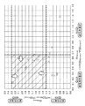
まず、短波長域のPSDMD1とPSDTD1とのバランスに着目し、次のような検討を行った。すなわち、媒体表面のMD方向における短波長域のPSD値の平均値PSDMD,shortと、媒体表面のTD方向における短波長域のPSD値の平均値PSDTD,shortとのバランス、すなわち比率PSDMD,short/PSDTD,shortに着目し鋭意検討を行った。その結果、この比率PSDMD,short/PSDTD,shortの調整のみでは、記録再生特性と信頼性とを両立することは困難であることを見出すに至った。具体的には以下のことを見出すに至った(図9参照)。0.65<PSDMD,short/PSDTD,shortであると、表面粗度の磁気記録媒体の走行方向成分が強く、記録再生特性が悪化するのに対して、信頼性は良好である。一方、PSDMD,short/PSDTD,short≦0.65であると、記録再生特性は向上するのに対して、信頼性は悪化する。 First, paying attention to the balance between PSD MD1 and PSD TD1 in the short wavelength region, the following examination was performed. That is, the balance between the average value PSD MD, short of the PSD value in the short wavelength region in the MD direction of the medium surface and the average value PSD TD, short of the PSD value in the short wavelength region in the TD direction of the medium surface, that is, the ratio PSD MD , short / PSD TD As a result, it has been found that it is difficult to achieve both recording / reproduction characteristics and reliability only by adjusting the ratio PSD MD, short / PSD TD, short . Specifically, the following has been found (see FIG. 9). When 0.65 <PSD MD, short / PSD TD, short , the running direction component of the surface roughness magnetic recording medium is strong and the recording / reproduction characteristics deteriorate, but the reliability is good. On the other hand, when PSD MD, short / PSD TD, short ≦ 0.65, the recording / reproduction characteristics are improved, but the reliability is deteriorated.
そこで、良好な記録再生特性が得られるPSDMD,short/PSDTD,short≦0.65の範囲において、信頼性を確保するために、記録再生特性への寄与が少なく、摩擦には効果的な長波長域のPSDMD1とPSDTD1とのバランスに着目し、次のような検討を行った。すなわち、媒体表面のMD方向における長波長域のPSD値の平均値PSDMD,longと、媒体表面のTD方向における長波長域のPSD値の平均値PSDTD,longとのバランス、すなわち比率PSDMD,long/PSDTD,longに着目し鋭意検討を行った。その結果、PSDMD,short/PSDTD,short≦0.65の範囲において、1.3≦PSDMD,long/PSDTD,long≦2.3とすることで、表面粗度の磁気記録媒体の走行方向成分を強くし、摩擦を下げるとともに、記録再生特性への影響を抑えることができ、これにより、記録再生特性と信頼性とを両立できることを見出すに至った(図9参照)。
以上により、発明者らは、本実施形態に係る磁気記録媒体を完成するに至った。
Therefore, in order to ensure reliability in the range of PSD MD, short / PSD TD, short ≦ 0.65 where good recording / reproduction characteristics can be obtained, the contribution to the recording / reproduction characteristics is small and effective for friction. Paying attention to the balance between PSD MD1 and PSD TD1 in the long wavelength region, the following examination was performed. That is, the balance between the average value PSD MD, long of the PSD value in the long wavelength region in the MD direction of the medium surface and the average value PSD TD, long of the PSD value in the long wavelength region in the TD direction of the medium surface, that is, the ratio PSD MD , long / PSD TD, Long attention was paid to the study. As a result, in the range of PSD MD, short / PSD TD, short ≦ 0.65, 1.3 ≦ PSD MD, long / PSD TD, long ≦ 2.3, the surface roughness of the magnetic recording medium It has been found that it is possible to increase the running direction component, reduce friction, and suppress the influence on the recording / reproducing characteristics, thereby achieving both the recording / reproducing characteristics and reliability (see FIG. 9).
As described above, the inventors have completed the magnetic recording medium according to this embodiment.
[1.2 磁気記録媒体の構成]
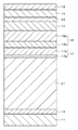
図1は、本技術の第1の実施形態に係る磁気記録媒体の構成の一例を模式的に示す断面図である。磁気記録媒体は、いわゆる単層垂直磁気記録媒体であり、基体11と、基体11の表面に設けられた積層膜とを備える。積層膜は、基体11の表面に設けられたシード層12と、シード層12の表面に設けられた下地層13と、下地層13の表面に設けられた磁気記録層14と、磁気記録層14の表面に設けられた保護層15と、保護層15の表面に設けられたトップコート層16とを備える。積層膜は、スパッタリング法により成膜されていることが好ましい。なお、本明細書では、軟磁性裏打ち層を持たない記録媒体を「単層垂直磁気記録媒体」と称し、軟磁性裏打ち層を有する記録媒体を「二層垂直磁気記録媒体」と称する。
[1.2 Configuration of magnetic recording medium]
FIG. 1 is a cross-sectional view schematically showing an example of the configuration of the magnetic recording medium according to the first embodiment of the present technology. The magnetic recording medium is a so-called single-layer perpendicular magnetic recording medium, and includes a
この磁気記録媒体は、今後ますます需要が高まることが期待されるデータアーカイブ用ストレージメディアとして用いて好適なものである。この磁気記録媒体は、例えば、現在のストレージ用塗布型磁気テープの10倍以上の面記録密度、すなわち50Gb/in2の面記録密度を実現することが可能である。このような面記録密度を有する磁気記録媒体を用いて、一般のリニア記録方式のデータカートリッジを構成した場合には、データカートリッジ1巻当たり50TB以上の大容量記録が可能になる。この磁気記録媒体は、リング型の記録ヘッドと巨大磁気抵抗効果(Giant Magnetoresistive:GMR)型の再生ヘッドを用いる記録再生装置に用いて好適なものである。 This magnetic recording medium is suitable for use as a data archiving storage medium that is expected to increase in demand in the future. This magnetic recording medium can realize, for example, a surface recording density of 10 times or more, that is, a surface recording density of 50 Gb / in 2 , compared with a current coated magnetic tape for storage. When a general linear recording type data cartridge is configured using a magnetic recording medium having such a surface recording density, a large capacity recording of 50 TB or more per data cartridge can be performed. This magnetic recording medium is suitable for use in a recording / reproducing apparatus using a ring type recording head and a giant magnetoresistive (GMR) type reproducing head.
(媒体表面)
磁気記録媒体は、長手方向(MD方向)および短手方向(TD方向)を持つ表面を有している。媒体表面における算術平均粗さRaと、比率PSDMD,short/PSDTD,short(=RPSD,short)と、比率PSDMD,long/PSDTD,long(=RPSD,long)とが、以下の関係式を満たしている。
Ra≦3.0nm
PSDMD,short/PSDTD,short≦0.65
1.3≦PSDMD,long/PSDTD,long≦2.3
(但し、PSDMD,short:媒体表面のMD方向における0.15μm以上0.4μm以下の範囲内のPSD値の平均値、PSDTD,short:媒体表面のTD方向における0.15μm以上0.4μm以下の範囲内のPSD値の平均値、PSDMD,long:媒体表面のMD方向における0.4μm以上5.0μm以下の範囲内のPSD値の平均値、PSDTD,long:媒体表面のTD方向における0.4μm以上5.0μm以下の範囲内のPSD値の平均値である。)
(Medium surface)
The magnetic recording medium has a surface having a longitudinal direction (MD direction) and a short direction (TD direction). The arithmetic average roughness Ra on the medium surface, the ratio PSD MD, short / PSD TD, short (= R PSD, short ), and the ratio PSD MD, long / PSD TD, long (= R PSD, long ) are as follows: Is satisfied.
Ra ≦ 3.0nm
PSD MD, short / PSD TD, short ≦ 0.65
1.3 ≦ PSD MD, long / PSD TD, long ≦ 2.3
(However, PSD MD, short : average value of PSD values in the range of 0.15 μm to 0.4 μm in the MD direction of the medium surface, PSD TD, short : 0.15 μm to 0.4 μm in the TD direction of the medium surface. Average value of PSD values in the following range, PSD MD, long : Average value of PSD values in the range of 0.4 μm to 5.0 μm in the MD direction of the medium surface, PSD TD, long : TD direction of the medium surface The average value of PSD values within the range of 0.4 μm to 5.0 μm in FIG.
上記関係式を満たすことで、記録再生特性と信頼性とを両立できる。具体的には、3.0nm<Raであると、記録再生特性が低下する。0.65<PSDMD,short/PSDTD,shortであると、記録再生特性が低下する。PSDMD,long/PSDTD,long<1.3であると、耐久性が低下する。2.3<PSDMD,long/PSDTD,longであると、記録再生特性が低下する。 By satisfying the above relational expression, it is possible to achieve both recording / reproduction characteristics and reliability. Specifically, when 3.0 nm <Ra, the recording / reproducing characteristics are deteriorated. If 0.65 <PSD MD, short / PSD TD, short , the recording / reproduction characteristics deteriorate. If PSD MD, long / PSD TD, long <1.3, the durability is lowered. If 2.3 <PSD MD, long / PSD TD, long , the recording / reproduction characteristics deteriorate.
(基体)
支持体となる基体11は、例えば、長尺状のフィルムであり、長手方向(MD方向)および短手方向(TD方向)を持つ表面を有している。基体11は、例えば、微細凹凸を持った凹凸面を有している。この場合、積層膜の表面は、基体11の凹凸面に倣った凹凸面であることが好ましい。上記関係式を満たす媒体表面の形成が容易であるからである。基体11としては、可撓性を有する非磁性基体を用いることが好ましい。非磁性基体の材料としては、例えば、通常の磁気記録媒体に用いられる可撓性の高分子樹脂材料を用いることができる。このような高分子材料の具体例としては、ポリエステル類、ポリオレフィン類、セルロース誘導体、ビニル系樹脂、ポリイミド類、ポリアミド類またはポリカーボネートなどが挙げられる。
(Substrate)
The base 11 serving as a support is, for example, a long film, and has a surface having a longitudinal direction (MD direction) and a short direction (TD direction). The
(シード層)
シード層12は、基体11と下地層13との間に設けられている。シード層12は、TiおよびCrを含む合金を含み、この合金はアモルファス状態を有していることが好ましい。具体的には、シード層12は、TiおよびCrを含む合金を含み、アモルファス状態を有していることが好ましい。また、この合金には、O(酸素)がさらに含まれていてもよい。この酸素は、例えば、スパッタリング法などの成膜法でシード層12を成膜する際に、シード層12内に微量に含まれる不純物酸素である。ここで、「シード層」とは、下地層13に類似した結晶構造を有し、結晶成長を目的として設けられる中間層ではなく、当該シード層12の平坦性およびアモルファス状態によって下地層13の垂直配向性を向上する中間層のことを意味する。「合金」とは、TiおよびCrを含む固溶体、共晶体、および金属間化合物などの少なくとも一種を意味する。「アモルファス状態」とは、電子線回折法により、ハローが観測され、結晶構造を特定できないことを意味する。
(Seed layer)
The
TiおよびCrを含む合金を含み、アモルファス状態を有するシード層12には、基体11に吸着したO2ガスやH2Oの影響を抑制するとともに、基体11の表面の凹凸を緩和して基体11の表面に金属性の平滑面を形成する作用がある。この作用により、下地層13の垂直配向性が向上する。なお、シード層12の状態を結晶状態にすると、結晶成長に伴うカラム形状が明瞭となり、基体11の表面の凹凸が強調され、下地層13の結晶配向が悪化する。
The
シード層12に含まれるTi、CrおよびO(酸素)の総量に対するOの割合は、好ましくは15原子%(atomic%:at%)以下、より好ましくは10原子%以下である。酸素の割合が15原子%を超えると、TiO2結晶が生成することにより、シード層12の表面に形成される下地層13の結晶核形成に影響を与えるようになり、下地層13の配向性が大きく低下する。
The ratio of O to the total amount of Ti, Cr, and O (oxygen) contained in the
シード層12に含まれるTiおよびCrの総量に対するTiの割合は、好ましくは30原子%以上100原子%以下、より好ましくは50原子%以上100原子%以下の範囲内である。Tiの比率が30%未満であると、Crの体心立方格子(Body-Centered Cubic lattice:bcc)構造の(100)面が配向するようになり、シード層12の表面に形成される下地層13の配向性が低下する。
The ratio of Ti to the total amount of Ti and Cr contained in the
なお、上記元素の割合は次のようにして求めることができる。磁気記録媒体のトップコート層16側からイオンビームによるエッチングを行い、エッチングされたシード層12の最表面についてオージェ電子分光法による解析を実施し、膜厚に対する平均の原子数比率をその元素の比率とする。具体的には、Ti、CrおよびOの3元素について解析を行い、その百分率比率による元素量を同定する。
In addition, the ratio of the said element can be calculated | required as follows. Etching with an ion beam is performed from the
シード層12に含まれる合金が、TiおよびCr以外の元素を添加元素としてさらに含んでいてもよい。この添加元素としては、例えば、Nb、Ni、Mo、AlおよびWなどからなる群より選ばれる1種以上の元素が挙げられる。
The alloy contained in the
(下地層)
下地層13は、磁気記録層14と同様の結晶構造を有していることが好ましい。磁気記録層14がCo系合金を含んでいる場合には、下地層13は、Co系合金と同様の六方細密充填(hcp)構造を有する材料を含み、その構造のc軸が膜面に対して垂直方向(すなわち膜厚方向)に配向していることが好ましい。磁気記録層14の配向性を高め、かつ、下地層13と磁気記録層14との格子定数のマッチングを比較的良好にできるからである。六方細密充填(hcp)構造を有する材料としては、Ruを含む材料を用いることが好ましく、具体的にはRu単体またはRu合金が好ましい。Ru合金としては、例えば、Ru−SiO2、Ru−TiO2またはRu−ZrO2などのRu合金酸化物が挙げられる。
(Underlayer)
The
(磁気記録層)
磁気記録層14は、記録密度を向上する観点から、Co系合金を含むグラニュラ磁性層であることが好ましい。このグラニュラ磁性層は、Co系合金を含む強磁性結晶粒子と、この強磁性結晶粒子を取り巻く非磁性粒界(非磁性体)とから構成されている。より具体的には、このグラニュラ磁性層は、Co系合金を含むカラム(柱状結晶)と、このカラムを取り囲み、それぞれのカラムを磁気的に分離する非磁性粒界(例えばSiO2などの酸化物)とから構成されている。この構造では、それぞれのカラムが磁気的に分離した構造を有する磁気記録層14を構成することができる。
(Magnetic recording layer)
The
Co系合金は、六方細密充填(hcp)構造を有し、そのc軸が膜面に対して垂直方向(膜厚方向)に配向している。Co系合金としては、少なくともCo、CrおよびPtを含有するCoCrPt系合金を用いることが好ましい。CoCrPt系合金は、特に限定されるものではなく、CoCrPt合金がさらに添加元素を含んでいてもよい。添加元素としては、例えば、NiおよびTaなどからなる群より選ばれる1種以上の元素が挙げられる。 The Co-based alloy has a hexagonal close-packed (hcp) structure, and the c-axis is oriented in the direction perpendicular to the film surface (film thickness direction). As the Co-based alloy, it is preferable to use a CoCrPt-based alloy containing at least Co, Cr, and Pt. The CoCrPt-based alloy is not particularly limited, and the CoCrPt alloy may further contain an additive element. Examples of the additive element include one or more elements selected from the group consisting of Ni and Ta.
強磁性結晶粒子を取り巻く非磁性粒界は、非磁性金属材料を含んでいる。ここで、金属には半金属を含むものとする。非磁性金属材料としては、例えば、金属酸化物および金属窒化物のうちの少なくとも一方を用いることができ、グラニュラ構造をより安定に維持する観点からすると、金属酸化物を用いることが好ましい。金属酸化物としては、Si、Cr、Co、Al、Ti、Ta、Zr、Ce、YおよびHfなどからなる群より選ばれる少なくとも1種以上の元素を含む金属酸化物が挙げられ、少なくともSi酸化物(すなわちSiO2)を含んでいる金属酸化物が好ましい。その具体例としては、SiO2、Cr2O3、CoO、Al2O3、TiO2、Ta2O5、ZrO2またはHfO2などが挙げられる。金属窒化物としては、Si、Cr、Co、Al、Ti、Ta、Zr、Ce、YおよびHfなどからなる群より選ばれる少なくとも1種以上の元素を含む金属窒化物が挙げられる。その具体例としては、SiN、TiNまたはAlNなどが挙げられる。グラニュラ構造をより安定に維持するためには、非磁性粒界が金属窒化物および金属酸化物のうち金属酸化物を含んでいることが好ましい。
The nonmagnetic grain boundary surrounding the ferromagnetic crystal grain contains a nonmagnetic metal material. Here, the metal includes a semi-metal. As the nonmagnetic metal material, for example, at least one of a metal oxide and a metal nitride can be used. From the viewpoint of maintaining a more stable granular structure, it is preferable to use a metal oxide. Examples of the metal oxide include a metal oxide containing at least one element selected from the group consisting of Si, Cr, Co, Al, Ti, Ta, Zr, Ce, Y, and Hf. Metal oxides containing the product (ie SiO 2 ) are preferred. Specific examples, SiO 2, Cr 2 O 3 , CoO, Al 2
SNR(Signal-Noise Ratio)の更なる向上を実現する観点からすると、強磁性結晶粒子に含まれるCoCrPt系合金と、非磁性粒界に含まれるSi酸化物とが、以下の式に示す平均組成を有していることが好ましい。反磁界の影響を抑え、かつ、十分な再生出力を確保できる飽和磁化量Msを実現でき、これにより、高いSNRを確保できるからである。
(CoxPtyCr100-x-y)100-z−(SiO2)z
(但し、式中において、x、y、zはそれぞれ、69≦X≦72、12≦y≦16、9≦Z≦12の範囲内の値である。)
From the viewpoint of further improving the SNR (Signal-Noise Ratio), the CoCrPt-based alloy contained in the ferromagnetic crystal grains and the Si oxide contained in the nonmagnetic grain boundaries are represented by the following average composition: It is preferable to have. This is because the saturation magnetization amount Ms that can suppress the influence of the demagnetizing field and secure a sufficient reproduction output can be realized, thereby ensuring a high SNR.
(Co x Pt y Cr 100- xy) 100-z - (SiO 2) z
(However, in the formula, x, y, and z are values within the ranges of 69 ≦ X ≦ 72, 12 ≦ y ≦ 16, and 9 ≦ Z ≦ 12, respectively.)
なお、上記組成は次のようにして求めることができる。磁気記録媒体のトップコート層16側からイオンビームによるエッチングを行い、エッチングされた磁気記録層12の最表面についてオージェ電子分光法による解析を実施し、膜厚に対する平均の原子数比率をその元素の比率とする。具体的には、Co、Pt、Cr、SiおよびOの5元素について解析を行い、その百分率比率による元素量を同定する。
The composition can be obtained as follows. Etching with an ion beam is performed from the
本実施形態に係る磁気記録媒体は、軟磁性材料を含む裏打ち層(軟磁性裏打ち層)を有さない単層磁気記録媒体であるが、この種の磁気記録媒体では、磁気記録層14に起因する垂直方向への反磁界の影響が大きいと、垂直方向への十分な記録が困難となる傾向がある。反磁界は、磁気記録層14の飽和磁化量Msに比例して大きくなるので、反磁界を抑えるためには飽和磁化量Msを小さくすることが望ましい。しかしながら、飽和磁化量Msが小さくなると、残留磁化量Mrが小さくなり、再生出力が低下する。したがって、磁気記録層14に含まれる材料は、反磁界の影響の抑制(すなわち飽和磁化量Msの低減)と、十分な再生出力を確保できる残留磁化量Mrとを両立する観点から選択することが好ましい。上記式の平均組成においては、これらの特性を両立し、高いSNRを確保できる。
The magnetic recording medium according to this embodiment is a single-layer magnetic recording medium that does not have a backing layer (soft magnetic backing layer) containing a soft magnetic material. In this type of magnetic recording medium, the
シード層12、下地層13および磁気記録層14のうち少なくとも隣接する2層は、Roll to Roll法により連続成膜されていることが好ましく、それらの3層すべてがRoll to Roll法により連続成膜されていることがより好ましい。磁気特性および記録再生特性を更に向上できるからである。
Of the
(保護層)
保護層15は、例えば、炭素材料または二酸化ケイ素(SiO2)を含み、保護層15の膜強度の観点からすると、炭素材料を含んでいることが好ましい。炭素材料としては、例えば、グラファイト、ダイヤモンド状炭素(Diamond-Like Carbon:DLC)またはダイヤモンドなどが挙げられる。
(Protective layer)
The
(トップコート層)
トップコート層16は、例えば潤滑剤を含んでいる。潤滑剤としては、例えば、シリコーン系潤滑剤、炭化水素系潤滑剤またはフッ素化炭化水素系潤滑剤などを用いることができる。
(Topcoat layer)
The
[1.3 スパッタ装置の構成]
図2は、本技術の第1の実施形態に係る磁気記録媒体の製造に用いられるスパッタ装置の構成の一例を示す概略図である。このスパッタ装置は、シード層12、下地層13および磁気記録層14の成膜に用いられる連続巻取式スパッタ装置であり、図2に示すように、成膜室21と、金属キャン(回転体)であるドラム22と、カソード23a〜23cと、供給リール24と、巻き取りリール25と、複数のガイドロール27、28とを備える。スパッタ装置は、例えばDC(直流)マグネトロンスパッタリング方式の装置であるが、スパッタリング方式はこの方式に限定されるものではない。
[1.3 Configuration of sputtering equipment]
FIG. 2 is a schematic diagram illustrating an example of a configuration of a sputtering apparatus used for manufacturing the magnetic recording medium according to the first embodiment of the present technology. This sputtering apparatus is a continuous winding type sputtering apparatus used for film formation of the
成膜室21は、排気口26を介して図示しない真空ポンプに接続され、この真空ポンプにより成膜室21内の雰囲気が所定の真空度に設定される。成膜室21の内部には、回転可能な構成を有するドラム22、供給リール24および巻き取りリール25が配置されている。成膜室21の内部には、供給リール24とドラム22との間における基体11の搬送をガイドするための複数のガイドロール27が設けられていると共に、ドラム22と巻き取りロール25との間における基体11の搬送をガイドするための複数のガイドロール28が設けられている。スパッタ時には、供給リール24から巻き出された基体11が、ガイドロール27、ドラム22およびガイドロール28を介して巻き取りリール25に巻き取られる。ドラム22は円柱状の形状を有し、細長い矩形状の基体11はドラム22の円柱面状の周面に沿わせて搬送される。ドラム22には、図示しない冷却機構が設けられており、スパッタ時には、例えば−20℃程度に冷却される。成膜室21の内部には、ドラム22の周面に対向して複数のカソード23a〜23cが配置されている。これらのカソード23a〜23cにはそれぞれターゲットがセットされている。具体的には、カソード23a、23b、23cにはそれぞれ、シート層12、下地層13、磁気記録層14を成膜するためのターゲットがセットされている。これらのカソード23a〜23cにより複数の種類の膜、すなわちシート層12、下地層13および磁気記録層14が同時に成膜される。
The
スパッタ時の成膜室21の雰囲気は、例えば、1×10⁻⁵Pa〜5×10⁻⁵Pa程度に設定される。シート層12、下地層13および磁気記録層14の膜厚および特性(例えば磁気特性)は、基体11を巻き取るテープライン速度、スパッタ時に導入するArガスの圧力(スパッタガス圧)、および投入電力などを調整することにより制御可能である。テープライン速度は、1m/min〜10m/min程度の範囲内であることが好ましい。スパッタガス圧は、0.1Pa〜5Pa程度の範囲内であることが好ましい。投入電力量は、30mW/mm2〜150mW/mm2程度の範囲内であることが好ましい。
Atmosphere of the
高分子材料を含む、厚みの薄い基体11の表面に、シート層12、下地層13および磁気記録層14を連続成膜する場合には、以下の(1)〜(4)の成膜条件のすべてを満たしていることが好ましい。
(1)ドラム22の温度が、好ましくは10℃以下、より好ましくは−20℃以下である。ここで、ドラム22の温度は、測温抵抗体、リニア抵抗、サーミスタなどを利用した回転体用の温度センサーをドラム22上にセットして測定したものである。
(2)ドラム22の周面のうち基体11が接触する領域の角度範囲θは、好ましくは220°以上360°未満、より好ましくは270°以上360°未満である。ここで、角度範囲は、図2に示すように、円柱状のドラム22の中心軸に対するドラム22の周面の円周方向の角度範囲を意味する。
(3)基体11の幅1mm長さ当たりの張力が、好ましくは4g/mm以上、より好ましくは4g/mm以上20g/mm以下である。ここで、張力は、基準とするガイドロール27、28の両側にかかる荷重をストレインゲージトランスデューサー(張力センサー)により計測したものである。
(4)シート層12、下地層13および磁気記録層14のダイナミックレートのうち最大のものが、好ましくは70nm・m/min以下である。ここで、ダイナミックレートとは、成膜膜厚と送り速度の積である。
When the
(1) The temperature of the
(2) The angle range θ of the region of the peripheral surface of the
(3) The tension per 1 mm width of the
(4) The maximum dynamic rate of the
上記(1)〜(4)の成膜条件を満たすことで、スパッタ時のプラズマからの輻射熱による基体11のダメージを抑制することができる。より具体的には、基体11の一部が変形したり、より深刻なケースでは成膜中に基体11に切断が発生したりすることなどを抑制することができる。また、上記(3)の成膜条件において張力の上限値を20g/mm以下とした場合には、磁気テープを巻き取った後のテンションで基体11上に積層した膜にクラックが発生することを抑制できる。
By satisfying the film forming conditions (1) to (4) above, damage to the
上述の構成を有するスパッタ装置では、シード層12、下地層13および磁気記録層14をRoll to Roll法により連続成膜または不連続成膜することができ、磁気特性および記録再生特性の更なる向上の観点からすると、連続成膜することが好ましい。連続成膜を採用する場合、シード層12、下地層13および磁気記録層14のうち少なくとも隣接する2層を、Roll to Roll法により連続成膜することが好ましく、それらの3層すべてをRoll to Roll法により連続成膜することがより好ましい。
In the sputtering apparatus having the above-described configuration, the
ここで、連続成膜とは、連接する下層(シード層12または下地層13)と上層(下地層13または磁気記録層14)とが成膜される間に、下層の表面状態に変化を招くことがない、より具体的には下層の表面に何らかの力が加えられることがない成膜のことを意味する。連続成膜プロセスの具体例としては、供給リール24から基体11を巻き出し、ドラム22を介して巻き取りリール25に巻き取る1回の工程で、走行する基体11の表面にシード層12、下地層13および磁気記録層14を順次成膜するプロセスが挙げられる。
Here, the continuous film formation means that the surface state of the lower layer is changed while the lower layer (the
一方、不連続成膜とは、連接する下層(シード層12または下地層13)と上層(下地層13または磁気記録層14)とが成膜される間に、下層の表面状態に変化を招いてしまう、より具体的には下層の表面に何らかの力が加えられてしまう成膜のことを意味する。不連続成膜プロセスの具体例としては、以下のプロセスが挙げられる。すなわち、供給リール24から基体11を巻き出し、ドラム22上で下層を基体11の表面に成膜し、巻き取りリール25に巻き取る。その後、再度巻き取りリール25から基体11を巻き出し、ドラム22上で上層を基体11の表面に成膜し、供給リール24に巻き取る。このプロセスでは、巻き取りリール25に基体11を巻き取るとき、および巻き取りリール25から基体11を巻き出すとき、下層の表面が複数のガイドロール28に接触するとともに、巻き取りリール25に基体11を巻き取ったときに下層の表面がその上に巻き取られる基体11の裏面に接触する。このため、下層の表面状態に変化を招くことになる。
On the other hand, the discontinuous film formation refers to a change in the surface state of the lower layer while the lower layer (
[1.4 磁気記録媒体の製造方法]
本技術の第1の実施形態に係る磁気記録媒体は、例えば、以下のようにして製造することができる。
[1.4 Magnetic Recording Medium Manufacturing Method]
The magnetic recording medium according to the first embodiment of the present technology can be manufactured, for example, as follows.
まず、図2に示したスパッタ装置を用いて、シード層12、下地層13および磁気記録層14を基体11の上に形成する。具体的には以下のようにして成膜する。まず、成膜室21を所定の圧力になるまで真空引きする。その後、成膜室21内にArガスなどのプロセスガスを導入しながら、カソード23a〜23cにセットされたターゲットをスパッタして、走行する基体11の表面にシード層12、下地層13および磁気記録層14を順次成膜する。
First, the
供給リール24から基体11を巻き出し、ドラム22を介して巻き取りリール25に巻き取る1回の工程で、走行する基体11の表面にシード層12、下地層13および磁気記録層14のうちの少なくとも隣接する2層を成膜することが好ましく、3層すべてを連続成膜することがより好ましい。なお、供給リール24から基体11を巻き出し、ドラム22を介して巻き取りリール25に巻き取る1回の工程で、隣接する2層(シード層12、下地層13)を成膜した場合には、再度巻き取りリール25から基体11を巻き出し、供給リール24に巻き取る更なる工程で、ドラム22上で残りの1層(磁気記録層14)が成膜される。
The
次に、磁気記録層14の表面に保護層15を形成する。保護層15の形成方法としては、例えば化学気相成長(Chemical Vapor Deposition:CVD)法または物理蒸着(physical vapor deposition:PVD)法を用いることができる。
Next, the
次に、例えば潤滑剤を保護層15の表面に塗布し、トップコート層16を形成する。潤滑剤の塗布方法はとしては、例えば、グラビアコーティング、ディップコーティングなどの各種塗布方法を用いることができる。
以上により、図1に示した磁気記録媒体が得られる。
Next, for example, a lubricant is applied to the surface of the
Thus, the magnetic recording medium shown in FIG. 1 is obtained.
[1.5 効果]
第1の実施形態に係る磁気記録媒体では、媒体表面における算術平均粗さRaと、比率PSDMD,short/PSDTD,shortと、比率PSDMD,long/PSDTD,longとが、以下の関係式を満たしている。これにより、記録再生特性と信頼性とを両立できる。
Ra≦3.0nm
PSDMD,short/PSDTD,short≦0.65
1.3≦PSDMD,long/PSDTD,long≦2.3
[1.5 Effect]
In the magnetic recording medium according to the first embodiment, the arithmetic average roughness Ra on the medium surface, the ratio PSD MD, short / PSD TD, short, and the ratio PSD MD, long / PSD TD, long have the following relationship: The expression is satisfied. This makes it possible to achieve both recording / reproduction characteristics and reliability.
Ra ≦ 3.0nm
PSD MD, short / PSD TD, short ≦ 0.65
1.3 ≦ PSD MD, long / PSD TD, long ≦ 2.3
第1の実施形態に係る磁気記録媒体は、以下の(1)および(2)の構成および作用を有していることが好ましい。
(1)基体11と下地層13との間に、アモルファス状態を有し、TiおよびCrを含む合金を含んでいるシード層12が設けられている。これにより、基体11に吸着したO2ガスやH2Oなどが下地層13に対して及ぼす影響を抑制するとともに、基体11の表面に金属性の平滑面を形成できる。
(2)シード層12に含まれるTiおよびCrの総量に対するTiの割合を、30原子%以上100原子%以下としている。これにより、Crの体心立方格子(bcc)構造の(100)面の配向を抑制できる。
上記(1)および(2)の構成および作用を有することで、下地層13および磁気記録層14の配向性を改善し、優れた磁気特性を達成することができる。したがって、高出力化および低ノイズ化といった媒体性能の向上を実現できる。
The magnetic recording medium according to the first embodiment preferably has the following configurations (1) and (2).
(1) A
(2) The ratio of Ti to the total amount of Ti and Cr contained in the
By having the configurations and operations (1) and (2) above, the orientation of the
また、第1の実施形態に係る磁気記録媒体では、シード層12が不純物酸素を含んでいる場合には、以下の(3)の構成および作用をさらに有していることが好ましい。
(3)シード層12に含まれるTi、CrおよびOの総量に対するOの割合を、15原子%以下としていることが好ましい。これにより、TiO2結晶が生成することを抑制し、シード層12の表面に形成される下地層13の結晶核形成に対する影響を抑制できる。
上記(3)の構成および作用をさらに有することで、シード層12が不純物酸素を含んでいる場合であっても、下地層13および磁気記録層14の配向性を改善し、優れた磁気特性を達成することができる。
Moreover, in the magnetic recording medium according to the first embodiment, when the
(3) The ratio of O to the total amount of Ti, Cr and O contained in the
By further having the configuration and action of (3) above, even if the
<2 第2の実施形態>
[2.1 磁気記録媒体の構成]
図3は、本技術の第2の実施形態に係る磁気記録媒体の構成の一例を模式的に示す断面図である。この第2の実施形態に係る磁気記録媒体は、図3に示すように、2層構造のシード層17を備える点において、第1の実施形態に係る磁気記録媒体とは異なっている。なお、第2の実施形態において第1の実施形態と同様の箇所には同一の符号を付して説明を省略する。
<2 Second Embodiment>
[2.1 Configuration of magnetic recording medium]
FIG. 3 is a cross-sectional view schematically showing an example of the configuration of the magnetic recording medium according to the second embodiment of the present technology. As shown in FIG. 3, the magnetic recording medium according to the second embodiment is different from the magnetic recording medium according to the first embodiment in that a
シード層17は、第1のシード層(上側シード層)17aおよび第2のシード層(下側シード層)17bを備える。第1のシード層17aが下地層13の側に設けられ、第2のシード層17bが基体11の側に設けられる。第2のシード層17bは、第1の実施形態におけるシード層12と同様のものを用いることができる。第1のシード層17aは、例えば第2のシード層17bとは異なる組成の材料を含んでいる。この材料の具体例としては、NiWまたはTaなどが挙げられる。なお、第1のシード層17aは、シード層ではなく、第2のシード層17bと下地層13との間に設けられた中間層と見なすことも可能である。
The
[2.2 効果]
磁気記録媒体が2層構造のシード層17を備えることで、下地層13および磁気記録層14の配向性をさらに改善し、磁気特性をさらに向上させることが可能となる。
[2.2 Effects]
When the magnetic recording medium includes the
<3 第3の実施形態>
[3.1 磁気記録媒体の構成]
図4は、本技術の第3の実施形態に係る磁気記録媒体の構成の一例を模式的に示す断面図である。この第3の実施形態に係る磁気記録媒体は、図4に示すように、2層構造の下地層18を備える点において、第2の実施形態に係る磁気記録媒体とは異なっている。なお、第3の実施形態において第2の実施形態と同様の箇所には同一の符号を付して説明を省略する。
<3 Third Embodiment>
[3.1 Configuration of magnetic recording medium]
FIG. 4 is a cross-sectional view schematically showing an example of the configuration of a magnetic recording medium according to the third embodiment of the present technology. As shown in FIG. 4, the magnetic recording medium according to the third embodiment is different from the magnetic recording medium according to the second embodiment in that a
下地層18は、第1の下地層(上側下地層)18aおよび第2の下地層(下側下地層)18bを備える。第1の下地層18aが磁気記録層14の側に設けられ、第2の下地層18bがシード層17の側に設けられる。
The
第1の下地層18a、第2の下地層18bの材料としては、ともに、例えば、上述の第1の実施形態における下地層13と同様のものを用いることができる。しかしながら、第1の下地層18a、第2の下地層18bそれぞれにおいて目的とする効果が異なっており、それ故にそれぞれのスパッタ条件は異なるものとなる。すなわち、第1の下地層18aについてはその上層となる磁気記録層のグラニュラ構造を促進する膜構造とすることが重要であり、第2の下地層18bについては結晶配向性の高い膜構造とすることが重要となる。
As materials for the
[3.2 効果]
磁気記録媒体が2層構造の下地層18を備えることで、磁気記録層14の配向性およびグラニュラ構造性をさらに改善し、磁気特性をさらに向上させることが可能となる。
[3.2 Effects]
Since the magnetic recording medium includes the
[3.3 変形例]
第3の実施形態に係る磁気記録媒体において、2層構造のシード層17に代えて単層構造のシード層を備えるようにしてもよい。単層構造のシード層としては、第1の実施形態におけるシード層12を用いることができる。
[3.3 Modification]
In the magnetic recording medium according to the third embodiment, a seed layer having a single layer structure may be provided instead of the
<4 第4の実施形態>
[4.1 磁気記録媒体の構成]
図5は、本技術の第4の実施形態に係る磁気記録媒体の構成の一例を模式的に示す断面図である。この第4の実施形態に係る磁気記録媒体は、いわゆる二層垂直磁気記録媒体であり、図5に示すように、基体11とシード層17との間に、シード層19および軟磁性裏打ち層(Soft magnetic underlayer、以下「SUL」という。)31を備える点において、第3の実施形態に係る磁気記録媒体とは異なっている。シード層19は基体11の側に設けられ、SUL31はシード層17の側に設けられる。この第4の実施形態に係る磁気記録媒体は、単磁極型(Single Pole Type:SPT)の記録ヘッドとトンネル磁気抵抗効果(Tunnel Magnetoresistive:TMR)型の再生ヘッドを用いる記録再生装置に用いて好適なものである。なお、第4の実施形態において第3の実施形態と同様の箇所には同一の符号を付して説明を省略する。
<4th Embodiment>
[4.1 Structure of magnetic recording medium]
FIG. 5 is a cross-sectional view schematically showing an example of the configuration of a magnetic recording medium according to the fourth embodiment of the present technology. The magnetic recording medium according to the fourth embodiment is a so-called double-layer perpendicular magnetic recording medium. As shown in FIG. 5, a
シード層19としては、第1の実施形態におけるシード層12と同様のものを用いることができる。
As the
SUL31の膜厚は、好ましくは40nm以上、より好ましくは40nm以上140nm以下である。40nm未満であると、記録再生特性が低下する傾向がある。一方、140nmを超えると、SUL膜の結晶粒の粗大化による下地層18の結晶配向性の低下が顕著となるとともに、SUL31の成膜時間が長くなり、生産性の低下を招く虞がある。SUL31は、アモルファス状態の軟磁性材料を含んでいる。軟磁性材料としては、例えば、Co系材料またはFe系材料などを用いることができる。Co系材料としては、例えば、CoZrNb、CoZrTa、CoZrTaNbなどが挙げられる。Fe系材料としては、例えば、FeCoB、FeCoZr、FeCoTaなどが挙げられる。
The film thickness of SUL31 is preferably 40 nm or more, more preferably 40 nm or more and 140 nm or less. If the thickness is less than 40 nm, the recording / reproducing characteristics tend to deteriorate. On the other hand, when the thickness exceeds 140 nm, the crystal orientation of the
SUL31はアモルファス状態を有するため、SUL31上に形成される層のエピタキシャル成長を促す役割を担わないが、SUL31の上に形成される下地層18の結晶配向を乱さないことが求められる。そのためには、軟磁性材料がカラムを形成しない微細な構造を有していることが必要となるが、基体11からの水分などのデガスの影響が大きい場合、軟磁性材料が粗大化し、SUL31上に形成される下地層18の結晶配向を乱してしまう。それらの影響を抑えるために、シード層19を基体11の表面に設けることが重要となる。特に、水分や酸素などの気体の吸着の多い、高分子材料のフィルムを基体11として用いる場合、それらの影響を抑えるためにシード層19を設けることが重要となる。
Since the
記録層14と保護層15との間にCAP層(スタック層)32をさらに備えることが好ましい。グラニュラ構造を有する磁気記録層14と、CAP層32とからなる積層構造は、一般にCoupled Granular Continuous(CGC)と呼ばれている。CAP層32の膜厚は、4nm以上12nm以下であることが好ましい。CAP層32の膜厚を4nm以上12nm以下の範囲内に選択することで、より良好な記録再生特性を得ることができる。CoCrPt系材料を含んでいる。CoCrPt系材料としては、例えば、CoCrPt、CoCrPtB、これら材料に金属酸化物をさらに添加した材料(CoCrPt−金属酸化物、CoCrPtB−金属酸化物)などが挙げられる。添加する金属酸化物としては、例えば、Si、Ti、Mg、TaおよびCrなどからなる群より選ばれる少なくとも1種を用いることができる。その具体例としては、SiO2、TiO2、MgO、Ta2O5、Cr2O3、それらの2種以上の混合体などが挙げられる。
Preferably, a CAP layer (stack layer) 32 is further provided between the
第4の実施形態に係る磁気記録媒体では、シード層19、SUL31、第1、第2のシード層17a、17b、第1、第2の下地層18a、18bおよび磁気記録層14のすべてがRoll to Roll法により連続成膜されていることが好ましい。磁気特性および記録再生特性を更に向上できるからである。
In the magnetic recording medium according to the fourth embodiment, all of the
[4.2 効果]
第4の実施形態に係る磁気記録媒体では、垂直磁性層である磁気記録層14の下にSUL31を設けることで、磁気記録層14の表層に発生する磁極の発生を減磁界を抑えるとともに、ヘッド磁束をSUL31中に誘導することにより、鋭いヘッド磁界の発生を助ける役割を果たす。また、基体11とSUL31との間にシード層19を設けているので、SUL31に含まれる軟磁性材料の粗大化を抑制することができる。すなわち、下地層18における結晶配向の乱れを抑制することができる。したがって、第1の実施形態よりも高い面記録密度を有する磁気記録媒体において、良好な記録再生特性を実現することができる。
[4.2 Effects]
In the magnetic recording medium according to the fourth embodiment, by providing the
グラニュラ構造を有する磁気記録層14上にCAP層32を設けた構造を採用した場合には、これらの磁気記録層14とCAP層32との間で交換相互作用による磁気的結合を発生させ、その効果により、Hc近傍でのM−Hループの傾きを急峻とすることで、記録を容易とすることができる。通常、磁気記録層14のみでM−Hループの傾きを急峻とした場合、ノイズの増大が観察されるが、この構造の場合には、ノイズを発生する記録の構造は低ノイズ構造を維持できるため、低ノイズでかつ記録が容易となる構造を実現できる。
When the structure in which the
[4.3 変形例]
第4の実施形態に係る磁気記録媒体において、2層構造のシード層17に代えて単層構造のシード層を備えるようにしてもよい。単層構造のシード層としては、第1の実施形態におけるシード層12を用いることができる。また、2層構造の下地層18に代えて単層構造の下地層を備えるようにしてもよい。単層構造の下地層としては、第1の実施形態における下地層13を用いることができる。
[4.3 Modification]
In the magnetic recording medium according to the fourth embodiment, a seed layer having a single layer structure may be provided instead of the
<5 第5の実施形態>
[5.1 磁気記録媒体の構成]
図6は、本技術の第5の実施形態に係る磁気記録媒体の構成の一例を模式的に示す断面図である。この第5の実施形態に係る磁気記録媒体は、図6に示すように、Antiparallel Coupled SUL(以下「APC−SUL」という。)33を備える点において、第4の実施形態に係る磁気記録媒体とは異なっている。なお、第5の実施形態において第4の実施形態と同様の箇所には同一の符号を付して説明を省略する。
<5 Fifth Embodiment>
[5.1 Structure of magnetic recording medium]
FIG. 6 is a cross-sectional view schematically showing an example of the configuration of a magnetic recording medium according to the fifth embodiment of the present technology. As shown in FIG. 6, the magnetic recording medium according to the fifth embodiment includes an antiparallel coupled SUL (hereinafter referred to as “APC-SUL”) 33, and the magnetic recording medium according to the fourth embodiment. Is different. Note that in the fifth embodiment, the same portions as those in the fourth embodiment are denoted by the same reference numerals, and description thereof is omitted.
APC−SUL33は、薄い中間層33bを介して2つの軟磁性層33a、33cを積層し、中間層33bを介した交換結合を利用して積極的に磁化を反平行に結合させた構造を有している。軟磁性層33a、33cの膜厚は略同一であることが好ましい。軟磁性層33a、33cのトータルの膜厚は、好ましくは40nm以上、より好ましくは40nm以上70nm以下である。40nm未満であると、記録再生特性が低下する傾向がある。一方、70nmを超えると、APC−SUL33の成膜時間が長くなり、生産性の低下を招く虞がある。軟磁性層33a、33cの材料は同一の材料であることが好ましく、その材料としては第4の実施形態におけるSUL31と同様の材料を用いることができる。中間層33bの膜厚は、例えば0.8nm以上1.4nm以下、好ましくは0.9nm以上1.3nm以下、より好ましくは1.1nm程度である。中間層33bの膜厚を0.9nm以上1.3nm以下の範囲内に選択することで、より良好な記録再生特性を得ることができる。中間層33bの材料としては、V,Cr,Mo,Cu,Ru,Rh,及びReが考えられ、特に、Ruを含んでいることが好ましい。
The APC-SUL 33 has a structure in which two soft
[5.2 効果]
第5の実施形態に係る磁気記録媒体では、APC−SUL33を用いているので、上層部である軟磁性層33aと下層部である軟磁性層33cとが反平行に交換結合し、残留磁化状態で上下層トータルの磁化量はゼロなる。これにより、APC−SUL33中の磁区が動いた場合に発生する、スパイク状のノイズの発生を抑えることができる。したがって、記録再生特性を更に向上することができる。
[5.2 Effects]
In the magnetic recording medium according to the fifth embodiment, since the APC-SUL 33 is used, the soft
[5.3 変形例]
第5の実施形態に係る磁気記録媒体において、第4の実施形態の変形例に係る磁気記録媒体と同様に、単層構造のシード層および/または下地層を備えるようにしてもよい。
[5.3 Modification]
The magnetic recording medium according to the fifth embodiment may be provided with a seed layer and / or an underlayer having a single layer structure, similarly to the magnetic recording medium according to the modification of the fourth embodiment.
以下、実施例により本技術を具体的に説明するが、本技術はこれらの実施例のみに限定されるものではない。 Hereinafter, the present technology will be specifically described by way of examples. However, the present technology is not limited only to these examples.
(実施例1〜7)
まず、高分子フィルムとして、算術平均粗さRaおよび比率RPSD,short(=PSDMD,short/PSDTD,short)、RPSD,long(=PSDMD,long/PSDTD,long)が以下の関係式を満たす微細凹凸を表面に有するものを準備した。
Ra≦3.0nm
RPSD,short≦0.65
1.3≦RPSD,long≦2.3
(Examples 1-7)
First, as a polymer film, arithmetic average roughness Ra and ratio R PSD, short (= PSD MD, short / PSD TD, short ), R PSD, long (= PSD MD, long / PSD TD, long ) are as follows: The thing which has the fine unevenness | corrugation on the surface which satisfy | fills a relational expression was prepared.
Ra ≦ 3.0nm
R PSD, short ≦ 0.65
1.3 ≦ R PSD, long ≦ 2.3
次に、準備した高分子フィルムの表面に、その表面の微細な凹凸の形状に倣うように複数の薄膜を積層した。これにより、高分子フィルムの表面の微細な凹凸の形状が、積層膜の表面でほぼ維持された。以下に、各薄膜の成膜工程に示す。 Next, a plurality of thin films were laminated on the surface of the prepared polymer film so as to follow the shape of fine irregularities on the surface. Thereby, the fine uneven | corrugated shape of the surface of a polymer film was substantially maintained on the surface of the laminated film. Below, it shows to the film-forming process of each thin film.
(第1のTiCrシード層の成膜工程)
まず、以下の成膜条件にて、非磁性基体としての高分子フィルム上に第1のTiCrシード層を5nm成膜した。
スパッタリング方式:DCマグネトロンスパッタリング方式
ターゲット:Ti50Cr50ターゲット
到達真空度:5×10⁻⁵Pa
ガス種:Ar
ガス圧:0.5Pa
(First TiCr seed layer deposition step)
First, a 5 nm first TiCr seed layer was formed on a polymer film as a nonmagnetic substrate under the following film formation conditions.
Sputtering method: DC magnetron sputtering method Target: Ti 50 Cr 50 target Ultimate vacuum: 5 × 10 −5 Pa
Gas type: Ar
Gas pressure: 0.5Pa
(第1の軟磁性層の成膜工程)
まず、以下の成膜条件にて、TiCrシード層上に第1の軟磁性層としてCoZrNb層を20nm成膜した。
スパッタリング方式:DCマグネトロンスパッタリング方式
ターゲット:CoZrNbターゲット
ガス種:Ar
ガス圧:0.1Pa
(First soft magnetic layer deposition step)
First, a CoZrNb layer having a thickness of 20 nm was formed as a first soft magnetic layer on a TiCr seed layer under the following film formation conditions.
Sputtering method: DC magnetron sputtering method Target: CoZrNb target Gas type: Ar
Gas pressure: 0.1 Pa
(Ru中間層の成膜工程)
次に、以下の成膜条件にて、CoZrNb層上にRu中間層を、表2に示すように0.8nm〜1.1nmの範囲で成膜した。
スパッタリング方式:DCマグネトロンスパッタリング方式
ターゲット:Ruターゲット
ガス種:Ar
ガス圧:0.3Pa
(Ru intermediate layer deposition process)
Next, a Ru intermediate layer was formed on the CoZrNb layer in the range of 0.8 nm to 1.1 nm as shown in Table 2 under the following film formation conditions.
Sputtering method: DC magnetron sputtering method Target: Ru target Gas type: Ar
Gas pressure: 0.3Pa
(第2の軟磁性層の成膜工程)
次に、以下の成膜条件にて、Ru中間層上に第2の軟磁性層としてCoZrNb層を20nm成膜した。
スパッタリング方式:DCマグネトロンスパッタリング方式
ターゲット:CoZrNbターゲット
ガス種:Ar
ガス圧:0.1Pa
(Deposition process of second soft magnetic layer)
Next, a CoZrNb layer having a thickness of 20 nm was formed as a second soft magnetic layer on the Ru intermediate layer under the following film formation conditions.
Sputtering method: DC magnetron sputtering method Target: CoZrNb target Gas type: Ar
Gas pressure: 0.1 Pa
(第2のTiCrシード層の成膜工程)
次に、以下の成膜条件にて、CoZrNb層上に第2のTiCrシード層を2.5nm成膜した。
スパッタリング方式:DCマグネトロンスパッタリング方式
ターゲット:Ti50Cr50ターゲット
到達真空度:5×10⁻⁵Pa
ガス種:Ar
ガス圧:0.5Pa
(Second TiCr seed layer deposition step)
Next, a second TiCr seed layer was deposited to 2.5 nm on the CoZrNb layer under the following deposition conditions.
Sputtering method: DC magnetron sputtering method Target: Ti 50 Cr 50 target Ultimate vacuum: 5 × 10 −5 Pa
Gas type: Ar
Gas pressure: 0.5Pa
(NiWシード層の成膜工程)
次に、以下の成膜条件にて、第2のTiCrシード層上にNiWシード層を10nm成膜した。
スパッタリング方式:DCマグネトロンスパッタリング方式
ターゲット:NiWターゲット
到達真空度:5×10⁻⁵Pa
ガス種:Ar
ガス圧:0.5Pa
(NiW seed layer deposition process)
Next, a 10 nm NiW seed layer was formed on the second TiCr seed layer under the following film forming conditions.
Sputtering method: DC magnetron sputtering method Target: NiW target Ultimate vacuum: 5 × 10 −5 Pa
Gas type: Ar
Gas pressure: 0.5Pa
(第1のRu下地層の成膜工程)
次に、以下の成膜条件にて、NiWシード層上に第1のRu下地層を10nm成膜した。
スパッタリング方式:DCマグネトロンスパッタリング方式
ターゲット:Ruターゲット
ガス種:Ar
ガス圧:0.5Pa
(First Ru underlayer film forming step)
Next, a 10 nm first Ru underlayer was deposited on the NiW seed layer under the following deposition conditions.
Sputtering method: DC magnetron sputtering method Target: Ru target Gas type: Ar
Gas pressure: 0.5Pa
(第2のRu下地層の成膜工程)
次に、以下の成膜条件にて、第1のRu下地層上に第2のRu下地層を20nm成膜した。
スパッタリング方式:DCマグネトロンスパッタリング方式
ターゲット:Ruターゲット
ガス種:Ar
ガス圧:1.5Pa
(Second Ru underlayer forming process)
Next, a second Ru underlayer was formed to a thickness of 20 nm on the first Ru underlayer under the following film formation conditions.
Sputtering method: DC magnetron sputtering method Target: Ru target Gas type: Ar
Gas pressure: 1.5Pa
(磁気記録層の成膜工程)
次に、以下の成膜条件にて、第2のRu下地層上に(CoCrPt)−(SiO2)磁気記録層を20nm成膜した。
スパッタリング方式:DCマグネトロンスパッタリング方式
ターゲット:(Co70Cr15Pt10)90−(SiO2)10ターゲット
ガス種:Ar
ガス圧:1.5Pa
(Deposition process of magnetic recording layer)
Next, a 20 nm thick (CoCrPt)-(SiO 2 ) magnetic recording layer was formed on the second Ru underlayer under the following film forming conditions.
Sputtering method: DC magnetron sputtering method Target: (Co 70 Cr 15 Pt 10 ) 90- (SiO 2 ) 10 target Gas type: Ar
Gas pressure: 1.5Pa
(CAP層の成膜工程)
次に、以下の成膜条件にて、(CoCrPt)−(SiO2)磁気記録層上に、CAP層としてのCoPtCrB層を8nm成膜した。
スパッタリング方式:DCマグネトロンスパッタリング方式
ターゲット:CoPtCrBターゲット
ガス種:Ar
ガス圧:1.5Pa
(CAP layer deposition process)
Next, an 8 nm CoPtCrB layer as a CAP layer was formed on the (CoCrPt)-(SiO 2 ) magnetic recording layer under the following film formation conditions.
Sputtering method: DC magnetron sputtering method Target: CoPtCrB target Gas type: Ar
Gas pressure: 1.5Pa
(保護層の成膜工程)
次に、以下の成膜条件にて、CoPtCrB層上に、カーボンからなる保護層を5nm成膜した。
スパッタリング方式:DCマグネトロンスパッタリング方式
ターゲット:カーボンターゲット
ガス種:Ar
ガス圧:1.0Pa
(Protective layer deposition process)
Next, a 5 nm thick protective layer made of carbon was formed on the CoPtCrB layer under the following film forming conditions.
Sputtering method: DC magnetron sputtering method Target: Carbon target Gas type: Ar
Gas pressure: 1.0Pa
(トップコート層の成膜工程)
次に、潤滑剤を保護層上に塗布し、保護層上にトップコート層を成膜した。
以上により、垂直磁気記録媒体である磁気テープを得た。
(Deposition process of topcoat layer)
Next, a lubricant was applied on the protective layer, and a topcoat layer was formed on the protective layer.
Thus, a magnetic tape as a perpendicular magnetic recording medium was obtained.
(比較例1〜4、8、10)
高分子フィルムとして算術平均粗さRaおよび比率RPSD,short、RPSD,longが以下の関係式を満たす微細凹凸を表面に有するものを準備する以外は実施例1と同様にして、磁気テープを得た。
Ra≦3.0nm
RPSD,short≦0.65
RPSD,long<1.3
(Comparative Examples 1-4, 8, 10)
A magnetic tape was prepared in the same manner as in Example 1 except that a polymer film having an arithmetic average roughness Ra and a ratio R PSD, short , R PSD, long having fine irregularities on the surface satisfying the following relational expression was prepared. Obtained.
Ra ≦ 3.0nm
R PSD, short ≦ 0.65
R PSD, long <1.3
(比較例5〜7)
高分子フィルムとして算術平均粗さRaおよび比率RPSD,short、RPSD,longが以下の関係式を満たす微細凹凸を表面に有するものを準備する以外は実施例1と同様にして、磁気テープを得た。
Ra≦3.0nm
0.65<RPSD,short
RPSD,long<1.3
(Comparative Examples 5-7)
A magnetic tape was prepared in the same manner as in Example 1 except that a polymer film having an arithmetic average roughness Ra and a ratio R PSD, short , R PSD, long having fine irregularities on the surface satisfying the following relational expression was prepared. Obtained.
Ra ≦ 3.0nm
0.65 <R PSD, short
R PSD, long <1.3
(比較例9)
高分子フィルムとして算術平均粗さRaおよび比率RPSD,short、RPSD,longが以下の関係式を満たす微細凹凸を表面に有するものを準備する以外は実施例1と同様にして、磁気テープを得た。
3.0nm<Ra
RPSD,short≦0.65
1.3≦RPSD,long≦2.3
(Comparative Example 9)
A magnetic tape was prepared in the same manner as in Example 1 except that a polymer film having an arithmetic average roughness Ra and a ratio R PSD, short , R PSD, long having fine irregularities on the surface satisfying the following relational expression was prepared. Obtained.
3.0 nm <Ra
R PSD, short ≦ 0.65
1.3 ≦ R PSD, long ≦ 2.3
上述のようにして得られた実施例1〜7、比較例1〜10の磁気テープ表面の比率RPSD,short、RPSD,long、算術平均粗さRaおよび摩擦について、以下のようにして評価した。 The ratios R PSD, short , R PSD, long , arithmetic average roughness Ra and friction of the magnetic tape surfaces of Examples 1 to 7 and Comparative Examples 1 to 10 obtained as described above were evaluated as follows. did.
(比率RPSD,short、RPSD,longの評価)
まず、磁気テープの表面を原子間力顕微鏡(Atomic Force Microscope:AFM)で観察し、2次元(2D)表面プロファイルデータを得た。
測定した。
以下に、測定に用いたAFMを示す。
Digital Instruments社製 Dimension 3100
カンチレバー:NanoWorld社 NCH-10T
以下に、AFMの測定条件について示す。
測定エリア:30μm×30μm
分解能:512×512
AFMのブローブのscan方向:磁気テープのMD方向(長手方向)
測定mode:タッピングモード
scan ratio:1Hz
(Evaluation of ratio R PSD, short and R PSD, long )
First, the surface of the magnetic tape was observed with an atomic force microscope (AFM) to obtain two-dimensional (2D) surface profile data.
It was measured.
The AFM used for the measurement is shown below.
Digital Instruments Dimension 3100
Cantilever: NanoWorld NCH-10T
The measurement conditions for AFM are shown below.
Measurement area: 30μm × 30μm
Resolution: 512 x 512
Scan direction of AFM probe: MD direction (longitudinal direction) of magnetic tape
Measurement mode: tapping mode scan ratio: 1 Hz
次に、得られた2D表面プロファイルデータに対して、下記のフィルタ処理を施した。
Flatten:3次
Planefit:MD方向のみ3次
Next, the following filtering process was performed on the obtained 2D surface profile data.
Flatten: 3rd order Planefit: 3rd order only in MD direction
次に、フィルタ処理後の2D表面プロファイルデータのMD方向に高速フーリエ変換(Fast Fourier Transform:FFT)を512lineそれぞれで施し、512本のパワースペクトル密度(Power Spectrum Density:PSD)を取得した。次に、取得したMD方向の512本のPSDを各波長毎に平均化し、MD方向の1本の平均化されたPSD(以下「PSDMD」または「PSD(k)MD」という。)を得た。次に、TD方向にも同一の処理を施し、TD方向の1本の平均化されたPSD(以下「PSDTD」または「PSD(k)TD」という。)を得た。なお、MD、TD方向におけるPSDの平均化には、以下の式(1)を用いた。上述のようにして得られたPSD(k)MD、PSD(k)TDをそれぞれPSD(λ)MD、PSD(λ)TD(但し、λ=L/k)に変換した結果を図7、図8に示す。 Next, Fast Fourier Transform (FFT) was applied to each of the 512 lines in the MD direction of the filtered 2D surface profile data to obtain 512 power spectrum densities (PSD). Next, the obtained 512 PSDs in the MD direction are averaged for each wavelength to obtain one averaged PSD in the MD direction (hereinafter referred to as “PSD MD ” or “PSD (k) MD ”). It was. Next, the same process was performed in the TD direction to obtain one averaged PSD in the TD direction (hereinafter referred to as “PSD TD ” or “PSD (k) TD ”). The following formula (1) was used for averaging the PSD in the MD and TD directions. The results obtained by converting PSD (k) MD and PSD (k) TD obtained as described above into PSD (λ) MD and PSD (λ) TD (where λ = L / k) are shown in FIGS. It is shown in FIG.

z(n):n番目の点での表面プロファイルデータ(surface profile data at point “n”)(nm)
d:分解能(resolution)(nm) =L/N
L:測定範囲(measurement length for X (or Y) direction)(30μm)
N:ポイント数(sampling point number for X (or Y) direction)(512points)
i:虚数単位(imaginary unit)
e:ネイピア数(Napier’s constant)
Average:平均化操作(averaging operation for Y (or X) direction)
n:変数(0 to N-1)
k:波数(0 to N-1)
なお、X directionはMD direction(長手方向)に対応し、Y directionはTD direction(短手方向)に対応する。
z (n): surface profile data at the nth point (surface profile data at point “n”) (nm)
d: resolution (nm) = L / N
L: Measurement length for X (or Y) direction (30 μm)
N: Sampling point number for X (or Y) direction (512 points)
i: imaginary unit
e: Napier's constant
Average: averaging operation (Y (or X) direction)
n: Variable (0 to N-1)
k: Wave number (0 to N-1)
X direction corresponds to MD direction (longitudinal direction), and Y direction corresponds to TD direction (short direction).
次に、0.15μm以上0.4μm以下の短波長域におけるPSDMDの平均値PSDMD,shortおよびPSDTDの平均値PSDTD,shortを求めた。次に、0.4μm以上5μm以下の長波長域におけるPSDMDの平均値PSDMD,longおよびPSDTDの平均値PSDTD,longを求めた。 Then, an average value was obtained PSD TD, short of average PSD MD, short and PSD TD of PSD MD at 0.4μm or less in the short wavelength range than 0.15 [mu] m. Then, an average value was obtained PSD TD, long the average PSD MD, long and PSD TD of PSD MD at 5μm or less in the long wavelength region than 0.4 .mu.m.
次に、求めた各平均値を以下の式(2)、(3)に代入して、比率RPSD,long、RPSD,shortを求めた。その結果を図9に示す。
比率RPSD,long=PSDMD,long/PSDTD,long (2)
比率RPSD,short=PSDMD,short/PSDTD,short (3)
Next, the obtained average values were substituted into the following formulas (2) and (3) to obtain the ratios R PSD, long and R PSD, short . The result is shown in FIG.
Ratio R PSD, long = PSD MD, long / PSD TD, long (2)
Ratio R PSD, short = PSD MD, short / PSD TD, short (3)
(算術平均粗さRaの評価)
まず、上述の“比率RPSD,short、RPSD,longの評価”と同様にして、フィルタ処理後の2次元表面プロファイルデータを得た。次に、以下の式(4)〜(6)を用いて算術平均粗さRaを求めた。その結果を図10に示す。
(Evaluation of arithmetic average roughness Ra)
First, the filtered two-dimensional surface profile data was obtained in the same manner as in the above-described “evaluation of ratios R PSD, short , R PSD, long ”. Next, arithmetic average roughness Ra was calculated | required using the following formula | equation (4)-(6). The result is shown in FIG.
N:ポイント数(512)
Z(m,n):測定位置(m,n)でのフィルター処理後の2Dプロファイルデータ
H(m,n):測定位置(m,n)での差分
| |:絶対値
m:長手方向の測定点を表す変数(0〜511)
n:幅方向の測定点を表す変数(0〜511)
なお、Z(m,n)、H(m,n)、A、Raの単位は“nm”である。
Z (m, n): 2D profile data after filtering at the measurement position (m, n) H (m, n): Difference at the measurement position (m, n) ||: Absolute value m: Longitudinal direction Variable representing the measurement point (0 to 511)
n: Variable (0 to 511) representing measurement points in the width direction
The unit of Z (m, n), H (m, n), A, and Ra is “nm”.
(記録再生特性の評価)
まず、ループテスター(Microphysics社製)を用いて、磁気テープの再生信号を取得した。以下に、再生信号の取得条件について示す。
head:GMR head
speed:2m/s
signal:単一記録周波数(10MHz)
記録電流:最適記録電流
(Evaluation of recording / reproduction characteristics)
First, a reproduction signal of the magnetic tape was obtained using a loop tester (manufactured by Microphysics). Hereinafter, the acquisition conditions of the reproduction signal will be described.
head: GMR head
speed: 2m / s
signal: Single recording frequency (10 MHz)
Recording current: optimum recording current
次に、再生信号をスペクトラムアナライザ(spectrum analyze)によりスパン(SPAN)0〜20MHz(resolution band width = 100kHz, VBW = 30kHz)で取り込んだ。次に、取り込んだスペクトルのピークを信号量Sとすると共に、ピークを除いたfloor noiseを積算して雑音量Nとし、信号量Sと雑音量Nの比S/NをSNR(Signal-to-Noise Ratio)として求めた。次に、求めたSNRを、リファレンスメディアとしての比較例5のSNRを基準とした相対値(dB)に変換した。その結果を表1に示す。 Next, the reproduced signal was captured with a spectrum analyzer (spectrum analyze) at a span (SPAN) of 0 to 20 MHz (resolution band width = 100 kHz, VBW = 30 kHz). Next, the peak of the acquired spectrum is set as a signal amount S, and floor noise excluding the peak is integrated to obtain a noise amount N, and a ratio S / N between the signal amount S and the noise amount N is SNR (Signal-to- Noise ratio). Next, the obtained SNR was converted into a relative value (dB) based on the SNR of Comparative Example 5 as a reference medium. The results are shown in Table 1.
(摩擦の評価)
まず、30cmの磁気テープ一端をテンションゲージに取り付け、他端に60gfの重りを取り付け、抱き角2度でArTiCバーに装着した。次に、テンションゲージを往復運動することで、磁気テープをArTiCバー上で往復させ、10往復後のテンションゲージの数値(摩擦力)を測定した。次に、リファレンスメディアとしての比較例5の摩擦力FAに対する各サンプルの摩擦力FBの割合RF(=(FB/FA)×100[%])を求めた。その結果を表1に示す。
(Evaluation of friction)
First, one end of a 30 cm magnetic tape was attached to a tension gauge, a weight of 60 gf was attached to the other end, and the ArTiC bar was attached at a holding angle of 2 degrees. Next, by reciprocating the tension gauge, the magnetic tape was reciprocated on the ArTiC bar, and the numerical value (friction force) of the tension gauge after 10 reciprocations was measured. Next, the ratio R F (= (F B / F A ) × 100 [%]) of the friction force F B of each sample with respect to the friction force F A of Comparative Example 5 as a reference medium was obtained. The results are shown in Table 1.
(評価結果)
表1に、実施例1〜7、比較例1〜10の磁気テープの評価結果を示す。
In Table 1, the evaluation result of the magnetic tape of Examples 1-7 and Comparative Examples 1-10 is shown.
表1、図9、図10から以下のことがわかる。
実施例1〜7では、Ra≦3.0nm、PSDMD,short/PSDTD,short≦0.65、1.3≦PSDMD,long/PSDTD,long≦2.3であるため、摩擦力が基準サンプルである比較例5より小さく、かつ、記録再生特性が基準サンプルである比較例5より向上している。
比較例1〜4、8、10では、PSDMD,long/PSDTD,long<1.3であるため、摩擦力が基準サンプルである比較例5より大きくなっている。
比較例6、7では、0.65<PSDMD,short/PSDTD,shortであるため、記録再生特性が基準サンプルである比較例5より悪化している。
比較例9では、3.0nm<Raであるため、記録再生特性が基準サンプルである比較例5より悪化している。
The following can be understood from Table 1, FIG. 9 and FIG.
In Examples 1 to 7, since Ra ≦ 3.0 nm, PSD MD, short / PSD TD, short ≦ 0.65, 1.3 ≦ PSD MD, long / PSD TD, long ≦ 2.3, friction force Is smaller than the comparative example 5 which is the reference sample, and the recording / reproducing characteristics are improved as compared with the comparative example 5 which is the reference sample.
In Comparative Examples 1-4, 8, and 10, since PSD MD, long / PSD TD, long <1.3, the frictional force is larger than that of Comparative Example 5 that is the reference sample.
In Comparative Examples 6 and 7, since 0.65 <PSD MD, short / PSD TD, short , the recording / reproducing characteristics are worse than those of Comparative Example 5 which is the reference sample.
In Comparative Example 9, since 3.0 nm <Ra, the recording / reproducing characteristics are worse than those of Comparative Example 5 which is the reference sample.
以上、本技術の実施形態について具体的に説明したが、本技術は、上述の実施形態に限定されるものではなく、本技術の技術的思想に基づく各種の変形が可能である。 As mentioned above, although embodiment of this technique was described concretely, this technique is not limited to the above-mentioned embodiment, Various deformation | transformation based on the technical idea of this technique is possible.
例えば、上述の実施形態において挙げた構成、方法、工程、形状、材料および数値などはあくまでも例に過ぎず、必要に応じてこれと異なる構成、方法、工程、形状、材料および数値などを用いてもよい。 For example, the configurations, methods, processes, shapes, materials, numerical values, and the like given in the above-described embodiments are merely examples, and different configurations, methods, processes, shapes, materials, numerical values, and the like are used as necessary. Also good.
また、上述の実施形態の構成、方法、工程、形状、材料および数値などは、本技術の主旨を逸脱しない限り、互いに組み合わせることが可能である。 The configurations, methods, processes, shapes, materials, numerical values, and the like of the above-described embodiments can be combined with each other without departing from the gist of the present technology.
また、上述の実施形態では、基体の凹凸表面に倣うように積層膜を成膜することで、磁気記録媒体の表面における算術均粗さRaと、比率PSDMD,short/PSDTD,shortと、比率PSDMD,long/PSDTD,longとが所定の関係式を満たすようにする例について示した。しかしながら、本技術はこの例に限定されるものではなく、これ以外の方法により算術均粗さRaと、比率PSDMD,short/PSDTD,shortと、比率PSDMD,long/PSDTD,longとが所定の関係式を満たすようにしてもよい。 Further, in the above-described embodiment, by forming a laminated film so as to follow the uneven surface of the substrate, the arithmetic average roughness Ra on the surface of the magnetic recording medium and the ratio PSD MD, short / PSD TD, short , An example is shown in which the ratio PSD MD, long / PSD TD, long satisfies a predetermined relational expression. However, the present technology is not limited to this example, and the arithmetic average roughness Ra, the ratio PSD MD, short / PSD TD, short, and the ratio PSD MD, long / PSD TD, long are obtained by other methods. May satisfy a predetermined relational expression.
また、本技術は以下の構成を採用することもできる。
(1)
長手方向および短手方向を持つ表面を有し、
上記表面における算術平均粗さRaと、比率PSDMD,short/PSDTD,shortと、比率PSDMD,long/PSDTD,longとが、以下の関係式を満たす磁気記録媒体。
Ra≦3.0nm
PSDMD,short/PSDTD,short≦0.65
1.3≦PSDMD,long/PSDTD,long≦2.3
(但し、PSDMD,short:上記表面の長手方向における0.15μm以上0.4μm以下の範囲内のPSD値の平均値、PSDTD,short:上記表面の短手方向における0.15μm以上0.4μm以下の範囲内のPSD値の平均値、PSDMD,long:上記表面の長手方向における0.4μm以上5.0μm以下の範囲内のPSD値の平均値、PSDTD,long:上記表面の短手方向における0.4μm以上5.0μm以下の範囲内のPSD値の平均値である。)
(2)
高分子樹脂を含む基体と、
上記基体上に積層された、上記表面を有する積層膜と
を含んでいる(1)に記載の磁気記録媒体。
(3)
上記基体は、凹凸面を有し、
上記積層膜の表面は、上記基体の凹凸面に倣った凹凸面である(2)に記載の磁気記録媒体。
(4)
上記積層膜は、スパッタリング法により成膜されている(2)または(3)に記載の磁気記録媒体。
(5)
上記積層膜は、シード層と、下地層と、記録層とを備え、
上記シード層は、上記基体と上記下地層との間に設けられている(2)から(4)のいずれかに記載の磁気記録媒体。
(6)
上記シード層は、アモルファス状態を有している(5)に記載の磁気記録媒体。
(7)
上記シード層は、TiおよびCrを含み、
上記シード層に含まれるTiおよびCrの総量に対するTiの割合は、30原子%以上100原子%以下である(5)または(6)に記載の磁気記録媒体。
(8)
上記シード層は、Ti、CrおよびOを含み、
上記シード層に含まれるTiおよびCrの総量に対するTiの割合は、30原子%以上100原子%以下であり、
上記シード層に含まれるTi、CrおよびOの総量に対するOの割合は、15原子%以下である(5)または(6)に記載の磁気記録媒体。
(9)
上記シード層により上記基体の表面の凹凸が緩和されている(5)から(8)のいずれかに記載の磁気記録媒体。
(10)
上記下地層は、Ruを含んでいる(5)から(9)のいずれかに記載の磁気記録媒体。
(11)
上記下地層は、第1の下地層と第2の下地層とを備え、
上記第1の下地層が上記記録層の側に設けられ、Ruを含んでいる(5)から(9)のいずれかに記載の磁気記録媒体。
(12)
上記記録層は、Co、PtおよびCrを含む粒子が酸化物で分離されたグラニュラ構造を有する(5)から(11)のいずれかに記載の磁気記録媒体。
(13)
上記記録層は、以下の式に示す平均組成を有している(5)から(12)のいずれかに記載の磁気記録媒体。
(CoxPtyCr100-x-y)100-z−(SiO2)z
(但し、式(1)中において、x、y、zはそれぞれ、69≦x≦72、12≦y≦16、9≦z≦12の範囲内の値である。)
(14)
上記シード層と上記下地層との間に設けられた別のシード層をさらに備える(5)から(13)のいずれかに記載の磁気記録媒体。
(15)
上記シード層と上記下地層との間に設けられた軟磁性層をさらに備える(5)から(14)のいずれかに記載の磁気記録媒体。
(16)
上記軟磁性層は、第1の軟磁性層と、中間層と、第2の軟磁性層とを備え、
上記中間層は、上記第1の軟磁性層と上記第2の軟磁性層との間に設けられている(15)に記載の磁気記録媒体。
(17)
上記軟磁性層と上記下地層との間に別のシード層をさらに備える(15)または(16)のいずれかに記載の磁気記録媒体。
(18)
上記記録層上に設けられた、Co、CrおよびPtを含む層をさらに備える(5)から(17)のいずれかに記載の磁気記録媒体。
(19)
上記シード層、上記下地層および上記記録層は、Roll to Roll法により連続成膜されている(5)から(18)のいずれかに記載の磁気記録媒体。
The present technology can also employ the following configurations.
(1)
Having a surface with a longitudinal direction and a transverse direction;
A magnetic recording medium in which the arithmetic average roughness Ra on the surface, the ratio PSD MD, short / PSD TD, short, and the ratio PSD MD, long / PSD TD, long satisfy the following relational expression.
Ra ≦ 3.0nm
PSD MD, short / PSD TD, short ≦ 0.65
1.3 ≦ PSD MD, long / PSD TD, long ≦ 2.3
(However, PSD MD, short is an average value of PSD values in the range of 0.15 μm to 0.4 μm in the longitudinal direction of the surface, PSD TD, short is 0.15 μm to 0.1 mm in the short direction of the surface. Average value of PSD values within a range of 4 μm or less, PSD MD, long : Average value of PSD values within a range of 0.4 μm or more and 5.0 μm or less in the longitudinal direction of the surface, PSD TD, long : Shortness of the surface (It is an average value of PSD values in the range of 0.4 μm to 5.0 μm in the hand direction.)
(2)
A substrate comprising a polymer resin;
The magnetic recording medium according to (1), comprising: a laminated film having the surface laminated on the substrate.
(3)
The base has an uneven surface,
The magnetic recording medium according to (2), wherein the surface of the laminated film is an uneven surface that follows the uneven surface of the substrate.
(4)
The magnetic recording medium according to (2) or (3), wherein the laminated film is formed by a sputtering method.
(5)
The laminated film includes a seed layer, an underlayer, and a recording layer,
The magnetic recording medium according to any one of (2) to (4), wherein the seed layer is provided between the base and the base layer.
(6)
The magnetic recording medium according to (5), wherein the seed layer has an amorphous state.
(7)
The seed layer includes Ti and Cr,
The magnetic recording medium according to (5) or (6), wherein a ratio of Ti to a total amount of Ti and Cr contained in the seed layer is 30 atomic percent or more and 100 atomic percent or less.
(8)
The seed layer includes Ti, Cr and O,
The ratio of Ti to the total amount of Ti and Cr contained in the seed layer is 30 atomic percent or more and 100 atomic percent or less,
The magnetic recording medium according to (5) or (6), wherein the ratio of O to the total amount of Ti, Cr, and O contained in the seed layer is 15 atomic% or less.
(9)
The magnetic recording medium according to any one of (5) to (8), wherein unevenness on the surface of the substrate is relaxed by the seed layer.
(10)
The magnetic recording medium according to any one of (5) to (9), wherein the underlayer includes Ru.
(11)
The underlayer includes a first underlayer and a second underlayer,
The magnetic recording medium according to any one of (5) to (9), wherein the first underlayer is provided on the recording layer side and includes Ru.
(12)
The magnetic recording medium according to any one of (5) to (11), wherein the recording layer has a granular structure in which particles containing Co, Pt, and Cr are separated by an oxide.
(13)
The magnetic recording medium according to any one of (5) to (12), wherein the recording layer has an average composition represented by the following formula.
(Co x Pt y Cr 100- xy) 100-z - (SiO 2) z
(However, in the formula (1), x, y, and z are values within the ranges of 69 ≦ x ≦ 72, 12 ≦ y ≦ 16, and 9 ≦ z ≦ 12, respectively.)
(14)
The magnetic recording medium according to any one of (5) to (13), further including another seed layer provided between the seed layer and the base layer.
(15)
The magnetic recording medium according to any one of (5) to (14), further including a soft magnetic layer provided between the seed layer and the underlayer.
(16)
The soft magnetic layer includes a first soft magnetic layer, an intermediate layer, and a second soft magnetic layer,
The magnetic recording medium according to (15), wherein the intermediate layer is provided between the first soft magnetic layer and the second soft magnetic layer.
(17)
The magnetic recording medium according to any one of (15) and (16), further comprising another seed layer between the soft magnetic layer and the underlayer.
(18)
The magnetic recording medium according to any one of (5) to (17), further comprising a layer containing Co, Cr, and Pt provided on the recording layer.
(19)
The magnetic recording medium according to any one of (5) to (18), wherein the seed layer, the underlayer, and the recording layer are continuously formed by a Roll to Roll method.
11 基体
12、17 シード層
13、18 下地層
14 磁気記録層
15 保護膜
16 トップコート層
21 成膜室
22 ドラム
23a、23b、23c カソード
24 供給リール
25 巻き取りリール
31 SUL
32 CAP層
33 APC−SUL
33a、33c 軟磁性層
33b 中間層
DESCRIPTION OF
32 CAP layer 33 APC-SUL
33a, 33c Soft magnetic layer 33b Intermediate layer
Claims (19)
上記表面における算術平均粗さRaと、比率PSDMD,short/PSDTD,shortと、比率PSDMD,long/PSDTD,longとが、以下の関係式を満たす磁気記録媒体。
Ra≦3.0nm
PSDMD,short/PSDTD,short≦0.65
1.3≦PSDMD,long/PSDTD,long≦2.3
(但し、PSDMD,short:上記表面の長手方向における0.15μm以上0.4μm以下の範囲内のPSD値の平均値、PSDTD,short:上記表面の短手方向における0.15μm以上0.4μm以下の範囲内のPSD値の平均値、PSDMD,long:上記表面の長手方向における0.4μm以上5.0μm以下の範囲内のPSD値の平均値、PSDTD,long:上記表面の短手方向における0.4μm以上5.0μm以下の範囲内のPSD値の平均値である。) Having a surface with a longitudinal direction and a transverse direction;
A magnetic recording medium in which the arithmetic average roughness Ra on the surface, the ratio PSD MD, short / PSD TD, short, and the ratio PSD MD, long / PSD TD, long satisfy the following relational expression.
Ra ≦ 3.0nm
PSD MD, short / PSD TD, short ≦ 0.65
1.3 ≦ PSD MD, long / PSD TD, long ≦ 2.3
(However, PSD MD, short is an average value of PSD values in the range of 0.15 μm to 0.4 μm in the longitudinal direction of the surface, PSD TD, short is 0.15 μm to 0.1 mm in the short direction of the surface. Average value of PSD values within a range of 4 μm or less, PSD MD, long : Average value of PSD values within a range of 0.4 μm or more and 5.0 μm or less in the longitudinal direction of the surface, PSD TD, long : Shortness of the surface (It is an average value of PSD values in the range of 0.4 μm to 5.0 μm in the hand direction.)
上記基体上に積層された、上記表面を有する積層膜と
を備える請求項1に記載の磁気記録媒体。 A long substrate containing a polymer resin;
The magnetic recording medium according to claim 1, further comprising: a laminated film having the surface laminated on the substrate.
上記積層膜の表面は、上記基体の凹凸面に倣った凹凸面である請求項2に記載の磁気記録媒体。 The base has an uneven surface,
The magnetic recording medium according to claim 2, wherein the surface of the laminated film is an uneven surface that follows the uneven surface of the substrate.
上記シード層は、上記基体と上記下地層との間に設けられている請求項2から4のいずれかに記載の磁気記録媒体。 The laminated film includes a seed layer, an underlayer, and a recording layer,
The magnetic recording medium according to claim 2, wherein the seed layer is provided between the base and the base layer.
上記シード層に含まれるTiおよびCrの総量に対するTiの割合は、30原子%以上100原子%以下である請求項5または6に記載の磁気記録媒体。 The seed layer includes Ti and Cr,
The magnetic recording medium according to claim 5 or 6 , wherein a ratio of Ti to a total amount of Ti and Cr contained in the seed layer is 30 atomic percent or more and 100 atomic percent or less.
上記シード層に含まれるTiおよびCrの総量に対するTiの割合は、30原子%以上100原子%以下であり、
上記シード層に含まれるTi、CrおよびOの総量に対するOの割合は、15原子%以下である請求項5または6に記載の磁気記録媒体。 The seed layer includes Ti, Cr and O,
The ratio of Ti to the total amount of Ti and Cr contained in the seed layer is 30 atomic percent or more and 100 atomic percent or less,
The proportion of O to the total amount of Ti, Cr and O contained in the seed layer, a magnetic recording medium according to claim 5 or 6 is 15 or less atomic%.
上記第1の下地層が上記記録層の側に設けられ、Ruを含んでいる請求項5から9のいずれかに記載の磁気記録媒体。 The underlayer includes a first underlayer and a second underlayer,
The magnetic recording medium according to claim 5, wherein the first underlayer is provided on the recording layer side and contains Ru.
(CoxPtyCr100-x-y)100-z−(SiO2)z
(但し、式中において、x、y、zはそれぞれ、69≦x≦72、12≦y≦16、9≦z≦12の範囲内の値である。) The recording layer is a magnetic recording medium according to any one of claims 5 to 12 having an average composition as shown in formula.
(Co x Pt y Cr 100- xy) 100-z - (SiO 2) z
(However, in the formula, x, y, and z are values within the ranges of 69 ≦ x ≦ 72, 12 ≦ y ≦ 16, and 9 ≦ z ≦ 12, respectively.)
上記中間層は、上記第1の軟磁性層と上記第2の軟磁性層との間に設けられている請求項15に記載の磁気記録媒体。 The soft magnetic layer includes a first soft magnetic layer, an intermediate layer, and a second soft magnetic layer,
The magnetic recording medium according to claim 15, wherein the intermediate layer is provided between the first soft magnetic layer and the second soft magnetic layer.
Priority Applications (3)
| Application Number | Priority Date | Filing Date | Title |
|---|---|---|---|
| JP2014001233A JP6083389B2 (en) | 2014-01-07 | 2014-01-07 | Magnetic recording medium |
| US14/568,423 US9542967B2 (en) | 2014-01-07 | 2014-12-12 | Magnetic recording medium |
| CN201410806556.XA CN104766613B (en) | 2014-01-07 | 2014-12-19 | Magnetic recording media |
Applications Claiming Priority (1)
| Application Number | Priority Date | Filing Date | Title |
|---|---|---|---|
| JP2014001233A JP6083389B2 (en) | 2014-01-07 | 2014-01-07 | Magnetic recording medium |
Publications (3)
| Publication Number | Publication Date |
|---|---|
| JP2015130214A JP2015130214A (en) | 2015-07-16 |
| JP2015130214A5 JP2015130214A5 (en) | 2016-03-10 |
| JP6083389B2 true JP6083389B2 (en) | 2017-02-22 |
Family
ID=53495700
Family Applications (1)
| Application Number | Title | Priority Date | Filing Date |
|---|---|---|---|
| JP2014001233A Active JP6083389B2 (en) | 2014-01-07 | 2014-01-07 | Magnetic recording medium |
Country Status (3)
| Country | Link |
|---|---|
| US (1) | US9542967B2 (en) |
| JP (1) | JP6083389B2 (en) |
| CN (1) | CN104766613B (en) |
Families Citing this family (98)
| Publication number | Priority date | Publication date | Assignee | Title |
|---|---|---|---|---|
| JP6303733B2 (en) | 2014-03-31 | 2018-04-04 | ソニー株式会社 | Magnetic recording medium, method for manufacturing the same, and film forming apparatus |
| JP6316248B2 (en) | 2015-08-21 | 2018-04-25 | 富士フイルム株式会社 | Magnetic tape and manufacturing method thereof |
| US10540996B2 (en) | 2015-09-30 | 2020-01-21 | Fujifilm Corporation | Magnetic tape having characterized magnetic layer and magnetic tape device |
| JP6552402B2 (en) | 2015-12-16 | 2019-07-31 | 富士フイルム株式会社 | Magnetic tape, magnetic tape cartridge, magnetic recording / reproducing apparatus, and method of manufacturing magnetic tape |
| US10403319B2 (en) | 2015-12-16 | 2019-09-03 | Fujifilm Corporation | Magnetic tape having characterized magnetic layer, tape cartridge, and recording and reproducing device |
| JP6430927B2 (en) | 2015-12-25 | 2018-11-28 | 富士フイルム株式会社 | Magnetic tape and manufacturing method thereof |
| JP6427127B2 (en) | 2016-02-03 | 2018-11-21 | 富士フイルム株式会社 | Magnetic tape and method of manufacturing the same |
| JP6465823B2 (en) | 2016-02-03 | 2019-02-06 | 富士フイルム株式会社 | Magnetic tape and manufacturing method thereof |
| JP6467366B2 (en) | 2016-02-29 | 2019-02-13 | 富士フイルム株式会社 | Magnetic tape |
| JP6472764B2 (en) | 2016-02-29 | 2019-02-20 | 富士フイルム株式会社 | Magnetic tape |
| JP6474748B2 (en) | 2016-02-29 | 2019-02-27 | 富士フイルム株式会社 | Magnetic tape |
| JP6926617B2 (en) * | 2016-04-18 | 2021-08-25 | 東レ株式会社 | Biaxially oriented laminated polyester film and magnetic recording medium |
| JP6556096B2 (en) | 2016-06-10 | 2019-08-07 | 富士フイルム株式会社 | Magnetic tape and magnetic tape device |
| JP6534637B2 (en) | 2016-06-13 | 2019-06-26 | 富士フイルム株式会社 | Magnetic tape and magnetic tape device |
| JP6534969B2 (en) | 2016-06-22 | 2019-06-26 | 富士フイルム株式会社 | Magnetic tape |
| JP6556100B2 (en) | 2016-06-22 | 2019-08-07 | 富士フイルム株式会社 | Magnetic tape |
| JP6549529B2 (en) | 2016-06-23 | 2019-07-24 | 富士フイルム株式会社 | Magnetic tape and magnetic tape device |
| JP6498154B2 (en) | 2016-06-23 | 2019-04-10 | 富士フイルム株式会社 | Magnetic tape and magnetic tape device |
| JP6549528B2 (en) | 2016-06-23 | 2019-07-24 | 富士フイルム株式会社 | Magnetic tape and magnetic tape device |
| JP6507126B2 (en) | 2016-06-23 | 2019-04-24 | 富士フイルム株式会社 | Magnetic tape and magnetic tape device |
| JP6496277B2 (en) | 2016-06-23 | 2019-04-03 | 富士フイルム株式会社 | Magnetic tape |
| JP6556101B2 (en) | 2016-06-23 | 2019-08-07 | 富士フイルム株式会社 | Magnetic tape and magnetic tape device |
| JP6556102B2 (en) | 2016-06-23 | 2019-08-07 | 富士フイルム株式会社 | Magnetic tape and magnetic tape device |
| JP6717684B2 (en) | 2016-06-23 | 2020-07-01 | 富士フイルム株式会社 | Magnetic tape and magnetic tape device |
| JP6529933B2 (en) | 2016-06-24 | 2019-06-12 | 富士フイルム株式会社 | Magnetic tape |
| JP6556107B2 (en) | 2016-08-31 | 2019-08-07 | 富士フイルム株式会社 | Magnetic tape |
| JP6552467B2 (en) | 2016-08-31 | 2019-07-31 | 富士フイルム株式会社 | Magnetic tape |
| JP6585570B2 (en) | 2016-09-16 | 2019-10-02 | 富士フイルム株式会社 | Magnetic recording medium and method for manufacturing the same |
| JP2018106778A (en) | 2016-12-27 | 2018-07-05 | 富士フイルム株式会社 | Magnetic tape device and magnetic reproducing method |
| JP6684204B2 (en) * | 2016-12-27 | 2020-04-22 | 富士フイルム株式会社 | Magnetic tape device and head tracking servo method |
| JP6684203B2 (en) | 2016-12-27 | 2020-04-22 | 富士フイルム株式会社 | Magnetic tape device and magnetic reproducing method |
| JP6701072B2 (en) | 2016-12-27 | 2020-05-27 | 富士フイルム株式会社 | Magnetic tape device and head tracking servo method |
| JP6588002B2 (en) | 2016-12-27 | 2019-10-09 | 富士フイルム株式会社 | Magnetic tape device and magnetic reproducing method |
| JP6649297B2 (en) | 2017-02-20 | 2020-02-19 | 富士フイルム株式会社 | Magnetic tape device and magnetic reproducing method |
| JP6684234B2 (en) | 2017-02-20 | 2020-04-22 | 富士フイルム株式会社 | Magnetic tape device and magnetic reproducing method |
| JP6684238B2 (en) | 2017-02-20 | 2020-04-22 | 富士フイルム株式会社 | Magnetic tape |
| JP6602806B2 (en) | 2017-02-20 | 2019-11-06 | 富士フイルム株式会社 | Magnetic tape |
| JP6685248B2 (en) | 2017-02-20 | 2020-04-22 | 富士フイルム株式会社 | Magnetic tape |
| JP6649298B2 (en) | 2017-02-20 | 2020-02-19 | 富士フイルム株式会社 | Magnetic tape device and head tracking servo method |
| JP6684235B2 (en) | 2017-02-20 | 2020-04-22 | 富士フイルム株式会社 | Magnetic tape device and head tracking servo method |
| JP6684239B2 (en) | 2017-02-20 | 2020-04-22 | 富士フイルム株式会社 | Magnetic tape |
| JP6689223B2 (en) | 2017-02-20 | 2020-04-28 | 富士フイルム株式会社 | Magnetic tape |
| JP6689222B2 (en) | 2017-02-20 | 2020-04-28 | 富士フイルム株式会社 | Magnetic tape |
| JP6684236B2 (en) | 2017-02-20 | 2020-04-22 | 富士フイルム株式会社 | Magnetic tape device and magnetic reproducing method |
| JP6602805B2 (en) | 2017-02-20 | 2019-11-06 | 富士フイルム株式会社 | Magnetic tape |
| JP6637456B2 (en) | 2017-02-20 | 2020-01-29 | 富士フイルム株式会社 | Magnetic tape |
| JP6684237B2 (en) | 2017-02-20 | 2020-04-22 | 富士フイルム株式会社 | Magnetic tape device and head tracking servo method |
| JP6866703B2 (en) * | 2017-03-14 | 2021-04-28 | 東レ株式会社 | Biaxially oriented polyester film and magnetic recording medium |
| JP6649313B2 (en) | 2017-03-29 | 2020-02-19 | 富士フイルム株式会社 | Magnetic tape device and magnetic reproducing method |
| JP6694844B2 (en) | 2017-03-29 | 2020-05-20 | 富士フイルム株式会社 | Magnetic tape device, magnetic reproducing method and head tracking servo method |
| JP6615814B2 (en) | 2017-03-29 | 2019-12-04 | 富士フイルム株式会社 | Magnetic tape device and head tracking servo method |
| JP6615815B2 (en) | 2017-03-29 | 2019-12-04 | 富士フイルム株式会社 | Magnetic tape device and head tracking servo method |
| JP6649312B2 (en) | 2017-03-29 | 2020-02-19 | 富士フイルム株式会社 | Magnetic tape device and magnetic reproducing method |
| JP6626031B2 (en) | 2017-03-29 | 2019-12-25 | 富士フイルム株式会社 | Magnetic tape device and magnetic reproducing method |
| JP6626032B2 (en) | 2017-03-29 | 2019-12-25 | 富士フイルム株式会社 | Magnetic tape device and magnetic reproducing method |
| JP6649314B2 (en) | 2017-03-29 | 2020-02-19 | 富士フイルム株式会社 | Magnetic tape device and head tracking servo method |
| JP6660336B2 (en) | 2017-03-29 | 2020-03-11 | 富士フイルム株式会社 | Magnetic tape device and head tracking servo method |
| JP6632561B2 (en) | 2017-03-29 | 2020-01-22 | 富士フイルム株式会社 | Magnetic tape device and magnetic reproducing method |
| JP6632562B2 (en) | 2017-03-29 | 2020-01-22 | 富士フイルム株式会社 | Magnetic tape |
| US11621020B2 (en) | 2017-04-07 | 2023-04-04 | Sony Corporation | Magnetic recording medium |
| JP6691512B2 (en) | 2017-06-23 | 2020-04-28 | 富士フイルム株式会社 | Magnetic recording medium |
| JP6723198B2 (en) | 2017-06-23 | 2020-07-15 | 富士フイルム株式会社 | Magnetic tape and magnetic tape device |
| JP6678135B2 (en) | 2017-07-19 | 2020-04-08 | 富士フイルム株式会社 | Magnetic recording media |
| US10839849B2 (en) | 2017-07-19 | 2020-11-17 | Fujifilm Corporation | Magnetic recording medium having characterized magnetic layer |
| JP6714548B2 (en) | 2017-07-19 | 2020-06-24 | 富士フイルム株式会社 | Magnetic tape and magnetic tape device |
| JP6717787B2 (en) | 2017-07-19 | 2020-07-08 | 富士フイルム株式会社 | Magnetic tape and magnetic tape device |
| JP6723203B2 (en) | 2017-07-19 | 2020-07-15 | 富士フイルム株式会社 | Magnetic tape |
| JP6723202B2 (en) | 2017-07-19 | 2020-07-15 | 富士フイルム株式会社 | Magnetic tape |
| US10854230B2 (en) | 2017-07-19 | 2020-12-01 | Fujifilm Corporation | Magnetic tape having characterized magnetic layer |
| US10854227B2 (en) | 2017-07-19 | 2020-12-01 | Fujifilm Corporation | Magnetic recording medium having characterized magnetic layer |
| JP6717786B2 (en) | 2017-07-19 | 2020-07-08 | 富士フイルム株式会社 | Magnetic tape and magnetic tape device |
| JP6707061B2 (en) | 2017-07-19 | 2020-06-10 | 富士フイルム株式会社 | Magnetic recording medium |
| JP6717785B2 (en) | 2017-07-19 | 2020-07-08 | 富士フイルム株式会社 | Magnetic recording medium |
| JP6707060B2 (en) | 2017-07-19 | 2020-06-10 | 富士フイルム株式会社 | Magnetic tape |
| JP6884220B2 (en) | 2017-09-29 | 2021-06-09 | 富士フイルム株式会社 | Magnetic tape and magnetic recording / playback device |
| US10978105B2 (en) | 2017-09-29 | 2021-04-13 | Fujifilm Corporation | Magnetic recording medium having characterized magnetic layer and magnetic recording and reproducing device |
| US10515657B2 (en) | 2017-09-29 | 2019-12-24 | Fujifilm Corporation | Magnetic tape having characterized magnetic layer and magnetic recording and reproducing device |
| WO2019065199A1 (en) | 2017-09-29 | 2019-04-04 | 富士フイルム株式会社 | Magnetic tape and magnetic recording/reproducing apparatus |
| US10854234B2 (en) | 2017-09-29 | 2020-12-01 | Fujifilm Corporation | Magnetic recording medium having characterized magnetic layer and magnetic recording and reproducing device |
| US10854231B2 (en) | 2017-09-29 | 2020-12-01 | Fujifilm Corporation | Magnetic recording medium having characterized magnetic layer and magnetic recording and reproducing device |
| US10854233B2 (en) | 2017-09-29 | 2020-12-01 | Fujifilm Corporation | Magnetic recording medium having characterized magnetic layer and magnetic recording and reproducing device |
| US11361792B2 (en) | 2018-03-23 | 2022-06-14 | Fujifilm Corporation | Magnetic tape having characterized magnetic layer and magnetic recording and reproducing device |
| US11514943B2 (en) | 2018-03-23 | 2022-11-29 | Fujifilm Corporation | Magnetic tape and magnetic tape device |
| US11514944B2 (en) | 2018-03-23 | 2022-11-29 | Fujifilm Corporation | Magnetic tape and magnetic tape device |
| US11361793B2 (en) | 2018-03-23 | 2022-06-14 | Fujifilm Corporation | Magnetic tape having characterized magnetic layer and magnetic recording and reproducing device |
| DE112019001706T5 (en) * | 2018-03-30 | 2021-01-21 | Sony Corporation | MAGNETIC RECORDING TAPE AND CASSETTE OF A MAGNETIC RECORDING TAPE |
| JP6830931B2 (en) | 2018-07-27 | 2021-02-17 | 富士フイルム株式会社 | Magnetic tapes, magnetic tape cartridges and magnetic tape devices |
| JP6784738B2 (en) | 2018-10-22 | 2020-11-11 | 富士フイルム株式会社 | Magnetic tapes, magnetic tape cartridges and magnetic tape devices |
| JP6830945B2 (en) | 2018-12-28 | 2021-02-17 | 富士フイルム株式会社 | Magnetic tapes, magnetic tape cartridges and magnetic tape devices |
| JP7042737B2 (en) | 2018-12-28 | 2022-03-28 | 富士フイルム株式会社 | Magnetic tape, magnetic tape cartridge and magnetic tape device |
| JP7091264B2 (en) * | 2019-01-31 | 2022-06-27 | 富士フイルム株式会社 | Magnetic tapes, magnetic tape cartridges and magnetic tape devices |
| JP7003073B2 (en) | 2019-01-31 | 2022-01-20 | 富士フイルム株式会社 | Magnetic tapes, magnetic tape cartridges and magnetic tape devices |
| JP7166042B2 (en) * | 2019-02-27 | 2022-11-07 | 富士フイルム株式会社 | Magnetic recording medium and magnetic recording/reproducing device |
| JP6985315B2 (en) | 2019-02-28 | 2021-12-22 | 富士フイルム株式会社 | Magnetic tape, magnetic tape cartridge and magnetic recording / playback device |
| JP6778804B1 (en) | 2019-09-17 | 2020-11-04 | 富士フイルム株式会社 | Magnetic recording medium and magnetic recording / playback device |
| JP6813069B1 (en) * | 2019-10-01 | 2021-01-13 | ソニー株式会社 | Magnetic recording medium, magnetic recording / playback device and magnetic recording medium cartridge |
| WO2021149680A1 (en) * | 2020-01-21 | 2021-07-29 | ソニーグループ株式会社 | Magnetic recording medium and cartridge |
| WO2023188674A1 (en) * | 2022-03-30 | 2023-10-05 | ソニーグループ株式会社 | Magnetic recording medium and cartridge |
Family Cites Families (12)
| Publication number | Priority date | Publication date | Assignee | Title |
|---|---|---|---|---|
| JP3467108B2 (en) * | 1995-02-10 | 2003-11-17 | 富士写真フイルム株式会社 | Magnetic recording media |
| JP2001256633A (en) * | 2000-03-10 | 2001-09-21 | Fuji Photo Film Co Ltd | Magnetic recording medium |
| JP3920008B2 (en) * | 2000-06-06 | 2007-05-30 | 帝人株式会社 | Laminated biaxially oriented polyester film |
| JP2003338023A (en) * | 2002-05-17 | 2003-11-28 | Fuji Photo Film Co Ltd | Magnetic recording medium |
| JP2005196885A (en) | 2004-01-08 | 2005-07-21 | Sony Corp | Magnetic recording medium |
| US20060019128A1 (en) * | 2004-07-22 | 2006-01-26 | Tdk Corporation | Magnetic recording medium and method for evaluating magnetic recording medium |
| JP2006318535A (en) * | 2005-05-10 | 2006-11-24 | Fuji Photo Film Co Ltd | Magnetic recording medium |
| JP2007257679A (en) * | 2006-03-20 | 2007-10-04 | Fujitsu Ltd | Magnetic recording medium, its manufacturing method, and magnetic storage device |
| US8236434B2 (en) * | 2006-03-31 | 2012-08-07 | Fujifilm Corporation | Magnetic recording medium, magnetic signal reproduction system and magnetic signal reproduction method |
| JP2008276833A (en) * | 2007-04-26 | 2008-11-13 | Hitachi Global Storage Technologies Netherlands Bv | Perpendicular magnetic recording medium and its manufacturing method |
| JP2008293552A (en) * | 2007-05-22 | 2008-12-04 | Fujitsu Ltd | Substrate, magnetic recording medium, its manufacturing method, and magnetic storage device |
| JP2009059431A (en) * | 2007-08-31 | 2009-03-19 | Showa Denko Kk | Magnetic recording medium and magnetic recording and reproducing apparatus |
-
2014
- 2014-01-07 JP JP2014001233A patent/JP6083389B2/en active Active
- 2014-12-12 US US14/568,423 patent/US9542967B2/en active Active
- 2014-12-19 CN CN201410806556.XA patent/CN104766613B/en active Active
Also Published As
| Publication number | Publication date |
|---|---|
| US9542967B2 (en) | 2017-01-10 |
| CN104766613A (en) | 2015-07-08 |
| CN104766613B (en) | 2019-03-19 |
| JP2015130214A (en) | 2015-07-16 |
| US20150194174A1 (en) | 2015-07-09 |
Similar Documents
| Publication | Publication Date | Title |
|---|---|---|
| JP6083389B2 (en) | Magnetic recording medium | |
| JP6307879B2 (en) | Magnetic recording medium and method for manufacturing the same | |
| JP6597775B2 (en) | Magnetic recording medium | |
| JP4893854B2 (en) | Method for manufacturing perpendicular magnetic recording medium | |
| JPWO2017122247A1 (en) | Magnetic recording medium | |
| JP6825573B2 (en) | Magnetic recording medium | |
| JPWO2016079971A1 (en) | Magnetic recording medium | |
| JP6205871B2 (en) | Magnetic recording medium | |
| JP6186859B2 (en) | Magnetic recording medium | |
| US9299378B2 (en) | Magnetic recording medium having a recording layer with a diffraction peak of magnetic atoms | |
| JP7074129B2 (en) | Magnetic recording medium | |
| US11232813B2 (en) | Film-forming apparatus and method for manufacturing magnetic recording medium | |
| WO2019187731A1 (en) | Magnetic recording tape and magnetic recording tape cartridge | |
| JPH11283228A (en) | Magnetic recording medium | |
| JP2006059397A (en) | Magnetic recording medium |
Legal Events
| Date | Code | Title | Description |
|---|---|---|---|
| A521 | Request for written amendment filed |
Free format text: JAPANESE INTERMEDIATE CODE: A523 Effective date: 20160121 |
|
| A621 | Written request for application examination |
Free format text: JAPANESE INTERMEDIATE CODE: A621 Effective date: 20160121 |
|
| A977 | Report on retrieval |
Free format text: JAPANESE INTERMEDIATE CODE: A971007 Effective date: 20161114 |
|
| TRDD | Decision of grant or rejection written | ||
| A01 | Written decision to grant a patent or to grant a registration (utility model) |
Free format text: JAPANESE INTERMEDIATE CODE: A01 Effective date: 20161227 |
|
| A61 | First payment of annual fees (during grant procedure) |
Free format text: JAPANESE INTERMEDIATE CODE: A61 Effective date: 20170109 |
|
| R151 | Written notification of patent or utility model registration |
Ref document number: 6083389 Country of ref document: JP Free format text: JAPANESE INTERMEDIATE CODE: R151 |
|
| R250 | Receipt of annual fees |
Free format text: JAPANESE INTERMEDIATE CODE: R250 |