JP2009151851A - Magnetic tape, magnetic tape apparatus, servo pattern recording apparatus, magnetic tape producing method, and recording method - Google Patents
Magnetic tape, magnetic tape apparatus, servo pattern recording apparatus, magnetic tape producing method, and recording method Download PDFInfo
- Publication number
- JP2009151851A JP2009151851A JP2007327102A JP2007327102A JP2009151851A JP 2009151851 A JP2009151851 A JP 2009151851A JP 2007327102 A JP2007327102 A JP 2007327102A JP 2007327102 A JP2007327102 A JP 2007327102A JP 2009151851 A JP2009151851 A JP 2009151851A
- Authority
- JP
- Japan
- Prior art keywords
- magnetic tape
- servo pattern
- recording
- information
- head
- Prior art date
- Legal status (The legal status is an assumption and is not a legal conclusion. Google has not performed a legal analysis and makes no representation as to the accuracy of the status listed.)
- Pending
Links
Images


Classifications
-
- G—PHYSICS
- G11—INFORMATION STORAGE
- G11B—INFORMATION STORAGE BASED ON RELATIVE MOVEMENT BETWEEN RECORD CARRIER AND TRANSDUCER
- G11B5/00—Recording by magnetisation or demagnetisation of a record carrier; Reproducing by magnetic means; Record carriers therefor
- G11B5/48—Disposition or mounting of heads or head supports relative to record carriers ; arrangements of heads, e.g. for scanning the record carrier to increase the relative speed
- G11B5/58—Disposition or mounting of heads or head supports relative to record carriers ; arrangements of heads, e.g. for scanning the record carrier to increase the relative speed with provision for moving the head for the purpose of maintaining alignment of the head relative to the record carrier during transducing operation, e.g. to compensate for surface irregularities of the latter or for track following
- G11B5/584—Disposition or mounting of heads or head supports relative to record carriers ; arrangements of heads, e.g. for scanning the record carrier to increase the relative speed with provision for moving the head for the purpose of maintaining alignment of the head relative to the record carrier during transducing operation, e.g. to compensate for surface irregularities of the latter or for track following for track following on tapes
Abstract
Description
本発明は、磁気テープ、磁気テープのサーボパターン記録装置、リニア型などの磁気テープ装置、磁気テープの製造方法及び記録方法に関する。
に関する。
The present invention relates to a magnetic tape, a servo pattern recording device for a magnetic tape, a magnetic tape device such as a linear type, a method for manufacturing a magnetic tape, and a recording method.
About.
従来、トラック追従サーボ制御の例は、長手方向データトラック群の間に予め記録された平行な長手方向サーボ・トラックを設け、その結果、1つまたは複数のサーボ・ヘッドがサーボ・トラックを読取ることができ、付随するトラック追従サーボが、ヘッドまたはテープのテープ幅方向の位置を調節して、サーボ・トラックに対して所望のテープ幅方向位置にサーボ・ヘッドを維持し、それによって、データ・ヘッドがデータトラックに対して中心に位置決めされるようにしている。 Traditionally, track following servo control examples provide pre-recorded parallel longitudinal servo tracks between longitudinal data tracks, so that one or more servo heads read the servo tracks. And an accompanying track following servo adjusts the position of the head or tape in the tape width direction to maintain the servo head in the desired tape width position relative to the servo track, thereby enabling the data head Is centered with respect to the data track.
トラック追従サーボ・システムについては、例えば特許文献1に記載されている。この特許文献1には、タイミング・ベース・サーボ・システムに関して記載されている。タイミング・ベース・サーボ・システムは、例えば、LTO(リニア・テープ・オープン)フォーマットとともに用いられ、その一例には、米国IBM社のLTO Ultrim(登録商標)磁気テープ・ドライブ及びそれに関連するテープ・カートリッジが含まれる。
A track following servo system is described in
リニア・サーボ・トラックは、例えば、あらかじめ記録された磁気遷移からなる感知可能な遷移パターンを含む。これらの遷移は、リニア・サーボ・トラックの上をテープ幅方向に延びる2つの異なるアジマス角配向の遷移の繰返し循環周期シーケンスからなるタイミング・ベース・サーボ・パターンを形成する。例えば、このパターンは、リニア・サーボ・トラックの方向に対して第1方向に傾斜した、すなわち第1方向のアジマス角配向を有する遷移と、反対方向に傾斜した、すなわち反対方向のアジマス角配向を有する遷移が交互に並ぶものを含み得る。このため、媒体がサーボ読取りヘッドに対して直線方向に移動すると、タイミング・ベース・サーボ・トラックに対するサーボ読取りヘッドのテープ幅方向位置は、異なるアジマス角配向を有する2つの遷移間の時間を、平行なアジマス角配向を有する2つの遷移間の時間と比較した尺度に基づいて感知される。このサーボ読取りヘッドによって読取られる遷移の相対的なタイミングは、ヘッドのテープ幅方向位置に応じて線形に変化する。そのため、複数の平行なデータトラックを、サーボ・トラックを横切る、異なるテープ幅方向位置と位置合せすることができる(例えば、特許文献1参照。)。
リニア型磁気テープ装置の面記録密度を高めるには、線密度を高めることは既に検討しつくしているので、トラック密度を上げることが最も効果的である。しかしながら、トラック密度を上げる際には次のような問題があることが知られている。即ち、トラッキング情報をいかにして感度を高く検出するか、一般的に用いられる2バンプ型のヘッドに対して、磁気テープの走行の傾きにどう対処するか、磁気テープの変形(幅方向、長手方向)にどう対応するか、ヘッドチャンネルスペーシングをどう小さくするかなどである。 In order to increase the surface recording density of the linear magnetic tape device, increasing the linear density has already been studied, so increasing the track density is the most effective. However, it is known that there are the following problems when increasing the track density. That is, how to detect tracking information with high sensitivity, how to cope with the inclination of the running of the magnetic tape with respect to a commonly used 2-bump type head, deformation of the magnetic tape (width direction, longitudinal direction) Direction) and how to reduce head channel spacing.
一般には、磁気テープを幅方向に複数(例えば4)に分割して、それぞれに磁気テープの幅方向にデータバンドとサーボバンドとを設ける。磁気テープ出荷時には、サーボバンドにトラッキングのためのサーボパターンが予め記録されている。データバンドにデータを書き込むとき、或いはデータを読取るときには、サーボパターンを再生して相対的なヘッドの位置情報(磁気テープの幅方向にその時々に特定な位置の情報)を検出し、記録ヘッドまたは再生ヘッドを常に正しい位置に維持している(トラッキングを取っている)。このため、ヘッドにはサーボパターンを再生するための追加チャンネルが、データチャンネルの外側に用意されている。 In general, a magnetic tape is divided into a plurality (eg, 4) in the width direction, and a data band and a servo band are provided in the width direction of the magnetic tape. When the magnetic tape is shipped, a servo pattern for tracking is recorded in advance in the servo band. When writing data to or reading data from the data band, the servo pattern is reproduced to detect the relative head position information (information at a specific position in the width direction of the magnetic tape from time to time) The playhead is always in the correct position (tracking). For this reason, an additional channel for reproducing the servo pattern is prepared in the head outside the data channel.
2バンプ型のヘッドを使用したリニア型の磁気テープ装置では、データ記録時には、上流のバンプの記録ヘッドで記録し、直後に下流のバンプの再生ヘッドで再生することにより、データが正しく記録されているかを確認している(これを「リードアフターライト」または「リードホワイルライト」と言う)。なお、以下においては、再生ヘッド(再生チャンネル)は、特に指定がない限り、上流(記録側)/下流(再生側)何れかのバンプにあるものを指す。 In a linear type magnetic tape apparatus using a two-bump type head, when data is recorded, data is recorded correctly by recording with the upstream bump recording head and then immediately reproducing with the downstream bump reproducing head. (This is called “lead after light” or “lead whistle light”). In the following description, the reproduction head (reproduction channel) indicates a bump on either the upstream (recording side) / downstream (reproduction side) bump unless otherwise specified.
2バンプ型のヘッドは、記録ヘッドの上に再生ヘッドが(或いはその逆)ピギーバックされているヘッドブロック2つを逆向きに合わせて、1つのヘッドとしているもので、第一のバンプに記録/再生ヘッド、第二のバンプに再生/記録(或いはこれらと逆の順序に)ヘッドを配置し、第一のバンプの記録ヘッドは第二のバンプの再生ヘッドと、また第一のバンプの再生ヘッドは第二のバンプの記録ヘッドとトラックの位置合わせをしてある。 A two-bump head is a head that has two head blocks that are piggybacked on the playback head (or vice versa) on the recording head. / Playback head, playback / recording (or reverse order) on the second bump, the first bump recording head is the second bump playback head, and the first bump playback The head is aligned with the recording head of the second bump and the track.
こうして記録ギャップと再生ギャップとを1ミリメートル前後離すことにより、記録ヘッドから再生ヘッドへのクロストークを軽減している。 In this way, the cross talk from the recording head to the reproducing head is reduced by separating the recording gap and the reproducing gap from about 1 mm.
また、記録時には、記録ヘッドと同じバンプにある再生ヘッドは、データチャンネルの外側にあるサーボ用チャンネルと言えども、記録ヘッドからのクロストークによりサーボ信号の再生には使用できない。従って、磁気テープの走行方向に離れた再生ヘッドのサーボチャンネルで、サーボ信号を検出して、記録ヘッドの位置の制御をすることになる。この状態で磁気テープの走行が傾くと、記録ヘッドの位置は、その分正しい位置から外れることになり、トラック密度を制約することになる。通常の方法では、磁気テープの走行の傾きの影響を軽減するには、第1のバンプのギャップラインと第2のバンプのギャップラインとの間の距離を近づけることになるが、クロストークの制約などがあり難しい。 Further, at the time of recording, a reproducing head that is on the same bump as the recording head cannot be used for reproducing servo signals due to crosstalk from the recording head, even though it is a servo channel outside the data channel. Therefore, the servo signal is detected in the servo channel of the reproducing head separated in the traveling direction of the magnetic tape, and the position of the recording head is controlled. If the running of the magnetic tape is tilted in this state, the position of the recording head deviates from the correct position accordingly, and the track density is restricted. In a normal method, in order to reduce the influence of the traveling inclination of the magnetic tape, the distance between the gap line of the first bump and the gap line of the second bump is made closer. It is difficult because there are.
即ち、トラッキング動作は常に再生ギャップを基準のトラックセンターに位置合わせしようとする。従って、テープがヘッドの前面を走行する方向(傾き)がダイナミックに変化(テープが蛇行)したときには、記録ギャップの位置は傾き角の正接と両ギャップ間の(長手方向の)距離に応じた量だけトラックずれ(トラックミスレジストレーション)を起こしてしまう。すなわち、記録トラックの位置がオフセットしたために、記録済みの隣接トラックの一部を上書きし、そのトラック幅を狭めることによりトラッキングマージンを削ることになる。なお、再生時には、データ再生とサーボ信号再生のヘッドが同一ギャップライン上にあるので、この問題(再生ギャップのトラックミスレジストレーション)は発生しない。厳密には、テープ走行が傾くと実効的にヘッドのトラック間距離が変化(減少)することによりトラックミスレジストレーションが起こるが、その効果は(1−傾き角の余弦)×データバンド幅/2、且つ再生ヘッドトラック<記録ヘッドトラック幅であり、影響は小さい。一方、記録時に記録側のバンプにある再生ギャップを用いてサーボ信号を検出できるかと言うと、記録ヘッドからのクロストークが邪魔をして難しい。 That is, the tracking operation always tries to align the reproduction gap with the reference track center. Therefore, when the direction (inclination) in which the tape runs in front of the head changes dynamically (tape meandering), the position of the recording gap is an amount corresponding to the tangent of the inclination angle and the distance between the gaps (in the longitudinal direction). Only track deviation (track misregistration) will occur. That is, because the position of the recording track is offset, a part of the recorded adjacent track is overwritten, and the tracking margin is reduced by narrowing the track width. At the time of reproduction, since the data reproduction and servo signal reproduction heads are on the same gap line, this problem (reproduction gap track misregistration) does not occur. Strictly speaking, when the tape travel is tilted, the track misregistration occurs due to the effective change (decrease) in the distance between the tracks of the head. The effect is (1−cosine of the tilt angle) × data bandwidth / 2. In addition, since the reproducing head track <the recording head track width, the influence is small. On the other hand, if it is possible to detect a servo signal by using a reproduction gap in a bump on the recording side during recording, crosstalk from the recording head is difficult because it interferes.
以上のような事情に鑑み、本発明の目的は、正確にデータを記録、再生することが可能な磁気テープ、該磁気テープのサーボパターン記録装置、該磁気テープの変形(幅と長手方向の伸縮)情報や磁気テープの傾き情報を検出することを可能とする磁気テープ装置、該磁気テープの製造方法及び該記録方法を提供することにある。 In view of the circumstances as described above, an object of the present invention is to provide a magnetic tape capable of accurately recording and reproducing data, a servo pattern recording device for the magnetic tape, and deformation of the magnetic tape (stretching in the width and longitudinal directions). ) To provide a magnetic tape device capable of detecting information and tilt information of the magnetic tape, a method for manufacturing the magnetic tape, and a recording method.
上記目的を達成するため、本発明に係る磁気テープは、データバンドを有する磁気テープにおいて、前記データバンドの全幅にわたって、且つ前記磁気テープの長手方向には間隔をあけて配置されたサーボパターンと、前記サーボパターン間に配置されたデータと、前記サーボパターンと前記データとの間に配置されたガードスペースとを具備する。 In order to achieve the above object, a magnetic tape according to the present invention, in a magnetic tape having a data band, and a servo pattern arranged across the entire width of the data band and in the longitudinal direction of the magnetic tape, Data disposed between the servo patterns and a guard space disposed between the servo pattern and the data.
すなわち、本発明は、2バンプ型ヘッドを用いた際に見られた磁気テープ走行の傾きの影響を軽減する磁気テープとしてエンベッデド型のサーボパターンを有する磁気テープを提供するものである。 That is, the present invention provides a magnetic tape having an embedded servo pattern as a magnetic tape that reduces the influence of the inclination of the magnetic tape running that is observed when a two-bump type head is used.
本発明では、データバンドの全幅にわたって、且つ前記磁気テープの長手方向には間隔をあけて配置されたサーボパターン間にデータが配置されている。すなわち、磁気テープの幅方向に一般には複数設けられるデータバンド上に、サーボパターン、ガードスペース、データ、ガードスペース、サーボパターン、ガードスペース、データ、・・・のように配置する。 In the present invention, data is arranged between servo patterns arranged at intervals in the entire width of the data band and in the longitudinal direction of the magnetic tape. In other words, servo patterns, guard spaces, data, guard spaces, servo patterns, guard spaces, data,... Are arranged on a plurality of data bands generally provided in the width direction of the magnetic tape.
このようにデータを記録するには、サーボパターンは予め記録されているものとして、記録開始時に先ず記録ヘッドと同じバンプにある再生チャンネルで、サーボパターンを通常複数個再生し(この間記録電流は流さない)ヘッドの位置を制御した後に、記録動作に入る。即ち、記録ヘッドに記録電流を流してデータを記録し、次にある時間経過後に(次のサーボパターンの直前で)記録電流を止める。再び同じバンプの再生ヘッドで次のサーボパターンを再生し、ヘッド位置情報を検出し、直後に再び記録に戻る。以下、この記録と再生とヘッド位置制御とを記録終了まで繰り返す。記録中には下流にあるバンプの再生ヘッドを用いてリードアフターライト(またはリードホワイルライトと言う)を行う。即ち、記録時に記録ヘッドと異なるバンプにある再生ヘッドを用いて記録ヘッドの位置決めをする場合には、磁気テープの走行が傾くことにより記録トラックの位置がずれて隣接トラックの領域に侵入すると言う問題(記録済み隣接トラックを上書きする、または後から記録の隣接トラックにより上書きされる可能性がある)が生じるのに対して、本発明では、同じバンプにある記録ヘッドと再生ヘッドとを時分割で交互にデータの記録と記録ヘッドの位置検出とに使用することにより、記録ヘッドにより近い(背中合わせになっている)再生ヘッドでサーボパターンを再生して、前記のテープが傾いて走行する際に生じる問題を回避して、データを正確な位置に記録することを可能にしている。また、記録時に、記録ヘッドから再生ヘッドへのクロストークの問題を解決することが出来る。 In order to record data in this way, it is assumed that the servo pattern has been recorded in advance, and at the start of recording, usually a plurality of servo patterns are reproduced on the reproduction channel on the same bump as the recording head. No) After the head position is controlled, the recording operation is started. That is, a recording current is supplied to the recording head to record data, and then the recording current is stopped after a certain time has elapsed (immediately before the next servo pattern). The next servo pattern is reproduced again by the reproducing head having the same bump, the head position information is detected, and immediately after that, the recording is resumed. Thereafter, the recording, reproduction and head position control are repeated until the recording is completed. During recording, read after-write (or read-foil write) is performed using a bump reproducing head located downstream. That is, when the recording head is positioned by using a reproducing head on a bump different from the recording head at the time of recording, the position of the recording track shifts and enters into the area of the adjacent track due to tilting of the running of the magnetic tape. In contrast, in the present invention, the recording head and the reproducing head on the same bump are divided in a time-sharing manner. By alternately using it for recording data and detecting the position of the recording head, the servo pattern is reproduced by a reproducing head closer to the recording head (back to back), and this occurs when the tape runs at an angle. It avoids problems and allows data to be recorded in the correct location. Further, the problem of crosstalk from the recording head to the reproducing head can be solved during recording.
再生時にはデータ再生に用いる再生ヘッド(どのバンプにある再生ヘッドを用いるかはヘッドブロックの設計にもよる)でサーボパターンも再生してヘッドの位置を制御する。 At the time of reproduction, the servo pattern is also reproduced by a reproducing head used for data reproduction (whether the reproducing head on which bump is used depends on the design of the head block) to control the position of the head.
データバンドとは、磁気テープを幅方向に分割して形成される磁気テープ全長にわたった領域である。データバンドは「データサブバンド×データの記録/再生を並列して行うヘッドのチャンネルの数」で構成される。データの記録/再生は、通常1つのデータバンドを終了してから次のデータバンドに移る。 The data band is an area extending over the entire length of the magnetic tape formed by dividing the magnetic tape in the width direction. The data band is composed of “data subband × number of head channels for performing data recording / reproduction in parallel”. In recording / reproducing data, normally, one data band is ended and then the next data band is started.
データサブバンドは、幅が2バンプ型ヘッドのチャンネルスペーシングで、磁気テープ全長にわたった領域である。並列記録/再生する多チャンネルヘッドの対応する1チャンネルが、1パス毎に磁気テープ幅方向に位置を変えて、規定回数の往復(1往復=2パス)で走査を完了する領域である。 The data subband is an area extending over the entire length of the magnetic tape with channel spacing of a two-bump type head. One channel corresponding to the multi-channel head for parallel recording / reproducing is an area in which scanning is completed by a predetermined number of reciprocations (1 reciprocation = 2 passes) by changing the position in the magnetic tape width direction for each pass.
ヘッドチャンネルスペーシングは、データの記録/再生を並列に行う多チャンネルヘッドの、隣り合うチャンネルそれぞれの中心線の間の距離である。必ずしも全てのチャンネルが単一のギャップライン上になくてもよい(2次元的にギャップが配置されていてもよい、或いは、複数のヘッドブロックに亘って隣接チャンネルがあってもよい)。 Head channel spacing is the distance between the center lines of adjacent channels of a multi-channel head that performs data recording / reproduction in parallel. Not all channels need to be on a single gap line (the gaps may be arranged two-dimensionally or there may be adjacent channels across multiple head blocks).
サーボパターンは、データバンドの全幅にまたがり(不連続でもよい)、幅方向に複数のセグメントから構成される。サーボパターンは、2バンプ型ヘッドを磁気テープ幅方向に位置制御する(トラッキングをとる)、或いは、磁気テープを速度制御/位相制御するのに用いる磁化遷移(反転)の組み合わせである。サーボパターンは、磁気テープの長手方向には間隔を空けて配置される。サーボパターンは、磁気テープの出荷時には予め磁気テープに記録されていて、個々の磁気テープ装置では書き換えない。セグメントの境界はアジマス角の変化点を結んだ仮想の線(磁気テープ長手方向の線)である。 The servo pattern spans the entire width of the data band (may be discontinuous) and is composed of a plurality of segments in the width direction. The servo pattern is a combination of magnetization transitions (reversal) used for position control (tracking) of the 2-bump type head in the width direction of the magnetic tape or speed control / phase control of the magnetic tape. The servo patterns are arranged at intervals in the longitudinal direction of the magnetic tape. The servo pattern is recorded in advance on the magnetic tape when the magnetic tape is shipped, and is not rewritten by individual magnetic tape devices. The segment boundaries are virtual lines (lines in the longitudinal direction of the magnetic tape) connecting the azimuth angle change points.
ガードスペースは、サーボパターンとデータバースト(データ)とを分離する領域(ギャップ)である。データ記録時に発生する、データバーストの磁気テープの長手方向の位置が変動するのを吸収する役目を負っている。フォーマット上必ず必要である。 The guard space is an area (gap) that separates the servo pattern and the data burst (data). It plays the role of absorbing fluctuations in the longitudinal position of the magnetic tape of the data burst that occur during data recording. Necessary for formatting.
前記サーボパターンを、その磁化遷移の境界の形状と同じ形状の記録ギャップを持つサーボパターン記録ヘッドで磁気テープ上に先ず記録し、次いで該記録したサーボパターンの一部を後続の全幅消去ヘッドでデータ記録部分を形成するように消去することで形成してもよい。磁化遷移は反転を含む。境界は磁気テープの記録面内にあり、磁化遷移(反転)は、記録電流の変化に基づいている。 The servo pattern is first recorded on the magnetic tape by a servo pattern recording head having a recording gap of the same shape as the boundary shape of the magnetization transition, and then a part of the recorded servo pattern is recorded by a subsequent full width erasing head. You may form by erasing so that a recording part may be formed. The magnetization transition includes inversion. The boundary is in the recording surface of the magnetic tape, and the magnetization transition (reversal) is based on the change in recording current.
これにより、走行方向の長さの短いサーボパターンを形成することができる。 As a result, a servo pattern having a short length in the traveling direction can be formed.
前記データバンド上で、前記サーボパターンを前記データバンドの幅方向に、少なくとも2つのセグメントから構成されるようになし、隣り合うセグメントを異なるアジマス角で記録するようになすことが好ましい。(セグメントの数>=アジマス角の数)
これにより、磁気ヘッドの位置決め情報(トラッキングの情報)磁気テープの速度情報に加えて、磁気テープの変形(幅と長手方向の伸縮)情報やテープの傾き情報を磁気テープ装置により検出することができる。
It is preferable that the servo pattern is formed of at least two segments in the width direction of the data band on the data band, and adjacent segments are recorded with different azimuth angles. (Number of segments> = number of azimuth angles)
Thereby, in addition to magnetic head positioning information (tracking information) magnetic tape speed information, magnetic tape deformation (width and longitudinal expansion / contraction) information and tape tilt information can be detected by the magnetic tape device. .
前記サーボパターンのそれぞれのセグメントに与えるアジマス角に、絶対値の等しい正と負、及び0度の3通りの中から少なくとも2つを用いてもよい。 As the azimuth angle given to each segment of the servo pattern, at least two of the positive, negative, and 0 degrees having the same absolute value may be used.
これにより、磁気ヘッドの位置決め情報(トラッキングの情報)磁気テープの速度情報に加えて、磁気テープの変形(幅と長手方向の伸縮)情報やテープの傾き情報を磁気テープ装置により検出することができる。 Thereby, in addition to magnetic head positioning information (tracking information) magnetic tape speed information, magnetic tape deformation (width and longitudinal expansion / contraction) information and tape tilt information can be detected by the magnetic tape device. .
前記サーボパターンを当該磁気テープの長手方向に等間隔に配置することが好ましい。 The servo patterns are preferably arranged at equal intervals in the longitudinal direction of the magnetic tape.
これにより、磁気テープにより周期的にサーボ情報を提供することができる。同時に、テープ速度制御を容易にする。 Thereby, servo information can be periodically provided by the magnetic tape. At the same time, it facilitates tape speed control.
前記データバンドの幅方向に、少なくとも2つのセグメントから構成されるようになしたサーボパターンの各セグメントの幅を、それぞれ前記データが記録されるデータトラックのトラックピッチの略整数倍にしてもよい。 The width of each segment of the servo pattern constituted by at least two segments in the width direction of the data band may be set to be approximately an integral multiple of the track pitch of the data track on which the data is recorded.
これにより、データバンドの幅方向にサーボパターンが複数のデータトラックに亘る。 As a result, the servo pattern extends over a plurality of data tracks in the width direction of the data band.
前記磁気テープの幅方向に前記データバンドが複数ある場合に、隣り合うデータバンドの間でそれぞれのサーボパターンの長手方向の位置を同一になすようにし、サーボパターンを形成する磁化遷移のアジマス角を隣り合うデータバンドの仮想の境界線を挟んだセグメント間で、符号の異なるアジマス角となしてもよい。磁化遷移とは反転を含み、アジマス角をデータバンドの仮想の境界線を挟んだセグメント間で共に0度としてもよい。 When there are a plurality of the data bands in the width direction of the magnetic tape, the longitudinal positions of the servo patterns are made to be the same between adjacent data bands, and the azimuth angle of the magnetization transition that forms the servo pattern is set. An azimuth angle with a different sign may be used between segments sandwiching a virtual boundary line between adjacent data bands. The magnetization transition includes reversal, and the azimuth angle may be set to 0 degree between the segments across the virtual boundary line of the data band.
或いは、前記磁気テープの幅方向に前記データバンドが複数ある場合に、隣り合うデータバンドの間でそれぞれのサーボパターンの長手方向の位置を略同一になすようにし、サーボパターンを形成する磁化遷移のアジマス角を隣り合うデータバンドの仮想の境界線を挟んだセグメント間で、同じ符号のアジマス角となしてもよい。磁化遷移は反転を含み、アジマス角をデータバンドの仮想の境界線を挟んだセグメント間で共に0度としてもよい。 Alternatively, when there are a plurality of the data bands in the width direction of the magnetic tape, the positions of the servo patterns in the longitudinal direction are made substantially the same between the adjacent data bands, and the transition of magnetization forming the servo pattern is performed. The azimuth angle may be the same as the azimuth angle between the segments across the virtual boundary line between adjacent data bands. The magnetization transition includes reversal, and the azimuth angle may be set to 0 degree between the segments across the virtual boundary line of the data band.
これらにより、磁気ヘッドの位置決め情報、磁気テープの変形情報および/または磁気テープの傾き情報を磁気テープ装置により検出することが出来る。後者はヘッド位置決め情報のダイナミックレンジを広げるのにも有効である。 Thus, the magnetic head positioning information, the magnetic tape deformation information and / or the magnetic tape tilt information can be detected by the magnetic tape device. The latter is also effective for expanding the dynamic range of head positioning information.
前記サーボパターンを、その磁化遷移の境界の形状と同じ形状の記録ギャップを持つサーボパターン全幅記録ヘッドで磁気テープ全幅を記録するに当たり、サーボパターン1つ当たりの記録電流の変化(反転を含む)の回数を全て奇数回或いは全て偶数回となすようにしてもよい。磁化遷移は反転を含む。境界は磁気テープの記録面内にあり、磁化遷移(反転)は、記録電流の変化に基づいている。 When recording the full width of the magnetic tape with the servo pattern full width recording head having a recording gap of the same shape as the boundary shape of the magnetization transition of the servo pattern, the change of the recording current per servo pattern (including reversal) The number of times may be all odd or all even. The magnetization transition includes inversion. The boundary is in the recording surface of the magnetic tape, and the magnetization transition (reversal) is based on the change in recording current.
これにより、サーボパターンに挟まれたデータ記録領域(データバーストを記録する領域)の初期の磁化の状態(方向)を、サーボパターンの前後で逆にまたは同じにすることを選択できる。即ち、磁気テープ上に形成される多数のデータ記録領域の初期の(磁気テープ装置により最初にデータを記録する前の)磁化の状態(方向)を交互に逆にまたは全て同じに出来る。 Thereby, it is possible to select that the initial magnetization state (direction) of the data recording area (data burst recording area) sandwiched between the servo patterns is reversed or the same before and after the servo pattern. That is, the initial magnetization states (directions) of a large number of data recording areas formed on the magnetic tape (before the first data recording by the magnetic tape device) can be reversed or all the same.
前記サーボパターンを、その磁化遷移の境界の形状と同じ形状の記録ギャップを持つサーボパターン全幅記録ヘッドで磁気テープ全幅を記録するに当たり、記録電流の変化のタイミングを変調してバイナリデータまたはユニークな同期信号を表現するようにしてもよい。磁化遷移は反転を含む。境界は磁気テープの記録面内にあり、磁化遷移(反転)は、記録電流の変化に基づいている。 When recording the full width of the magnetic tape with a servo pattern full width recording head having a recording gap of the same shape as the boundary shape of the magnetization transition of the servo pattern, binary data or unique synchronization is modulated by modulating the timing of change of the recording current. A signal may be expressed. The magnetization transition includes inversion. The boundary is in the recording surface of the magnetic tape, and the magnetization transition (reversal) is based on the change in recording current.
これにより、記録電流の変化(反転を含む)のタイミングを変調してバイナリデータまたはユニークな同期信号を表現することができる。 As a result, binary data or a unique synchronization signal can be expressed by modulating the timing of change (including inversion) of the recording current.
前記サーボパターンを、その磁化遷移の境界の形状と同じ形状の記録ギャップを持つサーボパターン記録ヘッドで磁気テープ上に先ず記録し、次いで該記録したサーボパターンの一部を後続の全幅消去ヘッドでデータ記録部分を形成するように消去するに当たり、記録電流の変調と後続の全幅消去ヘッドの動作タイミングを制御して、サーボパターン中にバイナリデータを表現するようになした、或いは、ユニークな同期信号を表現するようにしてもよい。磁化遷移は反転を含む。境界は磁気テープの記録面内にある。 The servo pattern is first recorded on the magnetic tape by a servo pattern recording head having a recording gap of the same shape as the boundary shape of the magnetization transition, and then a part of the recorded servo pattern is recorded by a subsequent full width erasing head. When erasing to form a recording portion, the modulation of the recording current and the operation timing of the subsequent full-width erasing head are controlled so that binary data is expressed in the servo pattern, or a unique synchronizing signal is generated. You may make it express. The magnetization transition includes inversion. The boundary is in the recording surface of the magnetic tape.
これにより、記録電流の変調と後続の全幅消去ヘッドの動作タイミングを制御して、サーボパターン中にバイナリデータまたはユニークな同期信号を表現することができる。 As a result, the modulation of the recording current and the operation timing of the subsequent full-width erasing head can be controlled to express binary data or a unique synchronization signal in the servo pattern.
前記サーボパターンを、1ビットのデータに対応させるようになした、或いは、ユニークな同期信号に対応させるようにしてもよい。 The servo pattern may correspond to 1-bit data, or may correspond to a unique sync signal.
これにより、サーボパターンにより1ビットのデータ、或いは、ユニークな同期信号を提供することができる。 Thereby, 1-bit data or a unique synchronization signal can be provided by the servo pattern.
前記アドレス情報をサーボパターンに挿入する際に、アドレス情報が挿入されているサーボパターンに対して、ユニークな同期信号が挿入されているサーボパターンを先行させることにより、アドレス情報のフレーム同期を確実に出来る。 When inserting the address information into the servo pattern, the servo pattern in which the unique synchronization signal is inserted precedes the servo pattern in which the address information is inserted, thereby ensuring frame synchronization of the address information. I can do it.
前記サーボパターンにアドレス情報を挿入する際に、該サーボパターン記録装置が扱える最長の磁気テープよりも充分に長いモジュロのアドレス発生器を用いると共に、前記サーボパターン記録装置に生の磁気テープを装填する毎に、前記アドレス発生器のアドレスをリセットするようになしたサーボパターン記録装置を用いて製造されてもよい。生の磁気テープとは未記録磁気テープを含む。 When address information is inserted into the servo pattern, a modulo address generator that is sufficiently longer than the longest magnetic tape that can be handled by the servo pattern recording device is used, and a raw magnetic tape is loaded into the servo pattern recording device. It may be manufactured by using a servo pattern recording device adapted to reset the address of the address generator every time. Raw magnetic tape includes unrecorded magnetic tape.
これにより、磁気テープにアドレス情報を記録することができる。 Thereby, address information can be recorded on the magnetic tape.
本発明に係る磁気テープ装置は、データバンドを有する磁気テープにおいて、前記データバンドの全幅にわたって、且つ前記磁気テープの長手方向には間隔をあけて配置されたサーボパターンとを具備する磁気テープに、前記サーボパターン間で、前記サーボパターンとの間にガードスペースを介してデータを記録する記録ヘッドと、前記磁気テープに記録されたデータを再生する再生ヘッドとを具備する。 A magnetic tape device according to the present invention is a magnetic tape having a data band, the servo tape having a servo pattern disposed across the entire width of the data band and in the longitudinal direction of the magnetic tape. A recording head for recording data between the servo patterns through a guard space between the servo patterns and a reproducing head for reproducing the data recorded on the magnetic tape are provided.
本発明では、磁気テープの幅方向に一般には複数設けられるデータバンド上に、サーボパターン、ガードスペース、データ、ガードスペース、サーボパターン、ガードスペース、データ、・・・のように配置されている。 In the present invention, servo patterns, guard spaces, data, guard spaces, servo patterns, guard spaces, data,... Are arranged on a plurality of data bands generally provided in the width direction of the magnetic tape.
このようにデータを記録するには、サーボパターンは予め記録されているものとして、記録開始時に先ず記録ヘッドと同じバンプにある再生チャンネルで、サーボパターンを通常複数個再生し(この間記録電流は流さない)ヘッドの位置を制御した後に、記録動作に入る。即ち、記録ヘッドに記録電流を流してデータを記録し、次にある時間経過後に(次のサーボパターンの直前で)記録電流を止める。再び同じバンプの再生ヘッドで次のサーボパターンを再生し、ヘッド位置情報を検出し、直後に再び記録に戻る。以下、この記録と再生とヘッド位置制御とを記録終了まで繰り返す。記録中には下流にあるバンプの再生ヘッドを用いてリードアフターライト(またはリードホワイルライトと言う)を行う。即ち、記録時に記録ヘッドと異なるバンプにある再生ヘッドを用いて記録ヘッドの位置決めをする場合には、磁気テープの走行が傾くことにより記録トラックの位置がずれて隣接トラックの領域に侵入すると言う問題(記録済み隣接トラックを上書きする、または後から記録の隣接トラックにより上書きされる可能性がある)が生じるのに対して、本発明では、同じバンプにある記録ヘッドと再生ヘッドとを時分割で交互にデータの記録と記録ヘッドの位置検出とに使用することにより、記録ヘッドにより近い(背中合わせになっている)再生ヘッドでサーボパターンを再生して、前記のテープが傾いて走行する際に生じる問題を回避して、データを正確な位置に記録することを可能にしている。また、記録時に、記録ヘッドから再生ヘッドへのクロストークの問題を解決することが出来る。 In order to record data in this way, it is assumed that the servo pattern has been recorded in advance, and at the start of recording, usually a plurality of servo patterns are reproduced on the reproduction channel on the same bump as the recording head. No) After the head position is controlled, the recording operation is started. That is, a recording current is supplied to the recording head to record data, and then the recording current is stopped after a certain time has elapsed (immediately before the next servo pattern). The next servo pattern is reproduced again by the reproducing head having the same bump, the head position information is detected, and immediately after that, the recording is resumed. Thereafter, the recording, reproduction and head position control are repeated until the recording is completed. During recording, read after-write (or read-foil write) is performed using a bump reproducing head located downstream. That is, when the recording head is positioned by using a reproducing head on a bump different from the recording head at the time of recording, the position of the recording track shifts and enters into the area of the adjacent track due to tilting of the running of the magnetic tape. In contrast, in the present invention, the recording head and the reproducing head on the same bump are divided in a time-sharing manner. By alternately using it for recording data and detecting the position of the recording head, the servo pattern is reproduced by a reproducing head closer to the recording head (back to back), and this occurs when the tape runs at an angle. It avoids problems and allows data to be recorded in the correct location. Further, the problem of crosstalk from the recording head to the reproducing head can be solved during recording.
再生時にはデータ再生に用いる再生ヘッド(どのバンプにある再生ヘッドを用いるかはヘッドブロックの設計にもよる)でサーボパターンも再生してヘッドの位置を制御する。 At the time of reproduction, the servo pattern is also reproduced by a reproducing head used for data reproduction (whether the reproducing head on which bump is used depends on the design of the head block) to control the position of the head.
これにより、磁気ヘッドの位置決め情報(トラッキングの情報)磁気テープの速度情報に加えて、磁気テープの変形(幅と長手方向の伸縮)情報やテープの傾き情報を磁気テープ装置により検出することが出来る。 Thus, in addition to magnetic head positioning information (tracking information) magnetic tape speed information, magnetic tape deformation (width and longitudinal expansion / contraction) information and tape tilt information can be detected by the magnetic tape device. .
前記サーボパターンの再生に、前記再生ヘッドのデータ用チャンネルの少なくとも2チャンネルを使用し、各チャンネルからの再生サーボ信号間の相関関係と、磁気テープ速度情報と、再生ヘッドのチャンネル情報とから、前記記録ヘッドまたは前記再生ヘッドの位置決め情報、前記磁気テープの変形情報、及び/または、磁気テープの傾き情報を検出するようにしてもよい。 For reproduction of the servo pattern, at least two channels of data channels of the reproduction head are used. From the correlation between reproduction servo signals from each channel, magnetic tape speed information, and reproduction head channel information, Positioning information of the recording head or the reproducing head, deformation information of the magnetic tape, and / or tilt information of the magnetic tape may be detected.
これにより、記録ヘッドまたは再生ヘッドの位置決め情報、磁気テープの変形情報、及び/または、磁気テープの傾き情報を検出することができる。 Thereby, the positioning information of the recording head or the reproducing head, the deformation information of the magnetic tape, and / or the tilt information of the magnetic tape can be detected.
前記サーボパターンの再生に、前記再生ヘッドのデータ用チャンネル及びサーボ用補助チャンネルの中から少なくとも2チャンネルを使用し、各チャンネルからの再生サーボ信号間の相関関係と、磁気テープ速度情報と、再生ヘッドのチャンネル情報とから、前記記録ヘッドまたは前記再生ヘッド位置決め情報、磁気テープの変形情報、及び/または、磁気テープの傾き情報を検出するようにしてもよい。 For reproduction of the servo pattern, at least two channels are used among the data channel and servo auxiliary channel of the reproduction head, the correlation between reproduction servo signals from each channel, magnetic tape speed information, and reproduction head The recording head or reproducing head positioning information, magnetic tape deformation information, and / or magnetic tape tilt information may be detected from the channel information.
これにより、記録ヘッドまたは再生ヘッドのヘッド位置決め情報、磁気テープの変形情報、及び/または、磁気テープの傾き情報を検出することができる。同時に、ヘッド位置決め情報検出のダイナミックレンジを広げるのにも有効である。 Thereby, the head positioning information of the recording head or the reproducing head, the deformation information of the magnetic tape, and / or the tilt information of the magnetic tape can be detected. At the same time, it is effective for expanding the dynamic range of head positioning information detection.
前記サーボパターンの異なるアジマス角のセグメントを、それぞれに対応する再生チャンネルで再生し、それぞれの出力信号の間の経過時間または該磁気テープ装置内の時計で計測した時刻差に、磁気テープ速度情報と、対応する再生チャンネルの組み合わせ毎に予め決められた基準値とを組み合わせて、前記記録ヘッドまたは前記再生ヘッドのトラック幅方向の位置決め情報を得るようにしてもよい。 Segments of different azimuth angles of the servo pattern are reproduced on the corresponding reproduction channels, and the elapsed time between the respective output signals or the time difference measured by the clock in the magnetic tape device, the magnetic tape speed information and Further, positioning information in the track width direction of the recording head or the reproducing head may be obtained by combining a reference value determined in advance for each combination of the corresponding reproducing channels.
これにより、記録ヘッドまたは再生ヘッドのトラック幅方向の位置決め情報を得ることができる。 Thereby, positioning information in the track width direction of the recording head or the reproducing head can be obtained.
前記サーボパターンの正のアジマス角のセグメントと負のアジマス角のセグメントを、それぞれに対応する再生チャンネルで再生してもよい。 A segment having a positive azimuth angle and a segment having a negative azimuth angle of the servo pattern may be reproduced by corresponding reproduction channels.
これにより、サーボパターンの正のアジマス角のセグメントと負のアジマス角のセグメントの情報をそれぞれ対応する再生チャンネルで再生することができる。 As a result, the information on the positive azimuth angle segment and the negative azimuth angle segment of the servo pattern can be reproduced on the corresponding reproduction channels.
前記サーボパターンの、正負の第一のアジマス角の組み合わせから得られた位置に関する第一の情報と、前記第一のアジマス角より大きな正負の第二のアジマス角の組み合わせから得られた位置に関する第二の情報とを組み合わせて、位置決め情報を得るようにしてもよい。第一の情報とは、例えば位置に関する低感度、広ダイナミックレンジの情報であり、第二の情報とは、例えば位置に関する高感度、狭ダイナミックレンジの情報である。 First information regarding a position obtained from a combination of positive and negative first azimuth angles of the servo pattern and a position obtained from a combination of second azimuth angles having a positive and negative value larger than the first azimuth angle. The positioning information may be obtained by combining the second information. The first information is, for example, low sensitivity and wide dynamic range information regarding the position, and the second information is, for example, high sensitivity and narrow dynamic range information regarding the position.
これにより、低感度の情報を用いてヘッド位置の粗調整を行い、次いで高感度の情報を用いて精密なヘッド位置合わせ(トラッキング)を可能とする。即ち、高感度と広ダイナミックレンジと言う相反する条件を満たすことが出来る。 Thereby, rough adjustment of the head position is performed using low-sensitivity information, and then precise head positioning (tracking) is enabled using high-sensitivity information. That is, the contradictory conditions of high sensitivity and wide dynamic range can be satisfied.
前記サーボパターンのアジマス角が0度ではないセグメントを、対応する2つの再生チャンネルで再生し、再生信号間の経過時間または該磁気テープ装置内の時計で計測した時刻差である第一の値と、これとは逆のアジマス角のセグメントを対応する第2の2つの再生チャンネルで再生して得られる第二の値と、磁気テープ速度情報と、再生ヘッドのチャンネル情報とを組み合わせて、磁気テープの変形情報、及び/または、磁気テープの傾き情報を検出するようにしてもよい。 A segment in which the azimuth angle of the servo pattern is not 0 degree is reproduced by two corresponding reproduction channels, and a first value which is an elapsed time between reproduction signals or a time difference measured by a clock in the magnetic tape device By combining the second value obtained by reproducing the segment having the azimuth angle opposite to this with the corresponding second two reproduction channels, the magnetic tape speed information, and the reproduction head channel information, the magnetic tape The deformation information and / or the tilt information of the magnetic tape may be detected.
これにより、磁気テープの変形情報、及び/または、磁気テープの傾き情報を検出することができる。 Thereby, deformation information of the magnetic tape and / or tilt information of the magnetic tape can be detected.
前記サーボパターンのアジマス角が0度のセグメントを、対応する2つの再生チャンネルで再生し、再生信号間の経過時間または装置内の時計で計測した時刻差と、磁気テープ速度情報と、再生ヘッドのチャンネル情報とを組み合わせて、磁気テープの傾き情報を検出するようにしてもよい。 A segment having an azimuth angle of 0 degrees of the servo pattern is reproduced on the corresponding two reproduction channels, the elapsed time between reproduction signals or the time difference measured with the clock in the apparatus, the magnetic tape speed information, the reproduction head The tilt information of the magnetic tape may be detected in combination with the channel information.
これにより、磁気テープの傾き情報を検出することができる。 Thereby, the inclination information of the magnetic tape can be detected.
前記サーボパターンの、0度ではない等しいアジマス角の第一の2つのセグメントを、第一の再生チャンネルペアでそれぞれ再生し、再生信号間の経過時間または該磁気テープ装置内の時計で計測した時刻差を得ると共に、これとは逆の等しいアジマス角の第二の2つのセグメントを、第二の再生チャンネルペアで再生して再生信号間の経過時間または時刻差を得、テープ速度情報と、再生ヘッドのチャンネル情報とを組み合わせて、磁気テープの変形情報と傾き情報との混合した情報を検出すると共に、アジマス角が0度のセグメントを第三の再生チャンネルペアで再生して検出される磁気テープの傾き情報を用いて、磁気テープ変形情報を得るようにしてもよい。 The first two segments of the servo pattern having equal azimuth angles other than 0 degrees are reproduced by the first reproduction channel pair, and the elapsed time between the reproduction signals or the time measured by the clock in the magnetic tape device The second two segments with the same azimuth angle, which are the opposite, are reproduced on the second reproduction channel pair to obtain the elapsed time or time difference between the reproduction signals, and the tape speed information and the reproduction are obtained. Magnetic tape detected by combining the head channel information and detecting the mixed information of the deformation information and the tilt information of the magnetic tape and reproducing the segment having the azimuth angle of 0 degree by the third reproduction channel pair Magnetic tape deformation information may be obtained using the tilt information.
これにより、磁気テープの傾き情報を用いて、磁気テープ変形情報を得ることができる。 Thereby, magnetic tape deformation information can be obtained using the tilt information of the magnetic tape.
前記出力信号間の経過時間または計測時刻差を、バースト位相比較器により位相差として検出するようにしてもよい。 The elapsed time or the measurement time difference between the output signals may be detected as a phase difference by a burst phase comparator.
これにより、バースト位相比較器により位相差(即ち、前記の時間情報)を検出することができる。 Thereby, the phase difference (that is, the time information) can be detected by the burst phase comparator.
前記記録ヘッドまたは前記再生ヘッドのトラック幅方向の位置決め情報を、前記磁気テープの変形情報、及び/または、前記傾き情報を用いて補正するようにしてもよい。 The positioning information in the track width direction of the recording head or the reproducing head may be corrected using the deformation information and / or the tilt information of the magnetic tape.
これにより、トラック幅方向でより正確な位置に記録ヘッド、及び/または、再生ヘッドを位置決めすることができる。 Thereby, the recording head and / or the reproducing head can be positioned at a more accurate position in the track width direction.
前記磁気テープの傾き情報に従って前記記録ヘッドまたは前記再生ヘッドの傾き角を制御するようにしてもよい。傾き角はアジマス角を含む。 The tilt angle of the recording head or the reproducing head may be controlled according to the tilt information of the magnetic tape. The tilt angle includes the azimuth angle.
これにより、より正確な位置に記録ヘッド、及び/または、再生ヘッドを位置決めすることができる。 Thereby, the recording head and / or the reproducing head can be positioned at a more accurate position.
前記磁気テープ速度情報を、設定されている速度情報(目標値)とした、及び/または、前記磁気テープ速度情報を、再生するサーボパターンの周期を計測して得るようにしてもよい。設定されている速度情報とは、速度の目標値の情報を含む。 The magnetic tape speed information may be set as speed information (target value) that has been set, and / or the magnetic tape speed information may be obtained by measuring the period of a servo pattern to be reproduced. The set speed information includes information on the target value of speed.
これにより、磁気テープ速度を得ることができる。 Thereby, the magnetic tape speed can be obtained.
前記サーボパターン中にアジマス角0度のセグメントがある場合に、このセグメントを再生するチャンネルの出力のサーボパターンの周期を計測して速度情報を得るようにしてもよい。 When there is a segment having an azimuth angle of 0 degrees in the servo pattern, the speed information may be obtained by measuring the period of the servo pattern output from the channel for reproducing the segment.
これにより、正確な速度情報を得ることができる。 Thereby, accurate speed information can be obtained.
前記サーボパターン中にアジマス角0度のセグメントがない場合に、アジマス角が正のセグメントに対応する再生チャンネルの出力のサーボパターンの周期と、負のセグメントに対応する再生チャンネルの出力のサーボパターンの周期とを計測し、それぞれのアジマス角の絶対値を考慮した演算を行って速度情報としてもよい。 If there is no segment with an azimuth angle of 0 degrees in the servo pattern, the period of the servo pattern output from the playback channel corresponding to the positive segment of the azimuth angle and the servo pattern output from the playback channel corresponding to the negative segment It is good also as speed information by measuring a period and performing the calculation which considered the absolute value of each azimuth angle.
α1, α2をサーボパターンの(既知の)アジマス角として、(n−1)番目のサーボパターンからn番目のサーボパターンまでテープが走行する間に、Δdだけテープが上がった(相対的にヘッドが下がった)とすると、
Δd1(〜dn−dn−1),dn−1,dn:n−1, nにおけるヘッドの位置(計算値)
T1=T01+Δd1tan(−α1+Δγ1), T1:n−1からnまでの時間(実測値)
T01=T1+Δd1tan(α1−Δγ1),T01:T1から求めた周期
Δγ1=arctan(Δd1/T01)<<α1
従って
T01=T1+Δd1tanα1
同様にして
T02=T2−Δd2tanα2
T0=(T01+T02)/2, T0:推定周期
T0=((T1+T2)/2)+Δd1tanα1−Δd2tanα2
正負のアジマス角のサーボパターンは、テープ上の長手方向に略同じ位置にあるから
Δd1=Δd2=Δd
よって
T0=((T1+T2)/2)+Δd(tanα1−tanα2)
尚、テープの変形を考慮する場合には上記α1,α2を(α1−β),(α2−β)とすればよい(例えば図18参照)。
α1 and α2 are the (known) azimuth angles of the servo pattern, and the tape is raised by Δd while the tape is running from the (n−1) th servo pattern to the nth servo pattern (relative to the head). Down)
Δd1 (˜dn−dn−1), dn−1, dn: n−1, position of head at n (calculated value)
T1 = T01 + Δd1tan (−α1 + Δγ1), T1: Time from n−1 to n (actual measurement value)
T01 = T1 + Δd1tan (α1−Δγ1), T01: period obtained from T1 Δγ1 = arctan (Δd1 / T01) << α1
Therefore, T01 = T1 + Δd1tanα1
Similarly, T02 = T2-Δd2tan α2
T0 = (T01 + T02) / 2, T0: estimation period T0 = ((T1 + T2) / 2) + Δd1 tan α1−Δd2 tan α2
Since the servo patterns with positive and negative azimuth angles are substantially at the same position in the longitudinal direction on the tape, Δd1 = Δd2 = Δd
Therefore, T0 = ((T1 + T2) / 2) + Δd (tan α1-tan α2)
When considering the deformation of the tape, α1 and α2 may be (α1−β) and (α2−β) (see, for example, FIG. 18).
これにより、サーボパターン中にアジマス角0度のセグメントがない場合にも速度情報を得ることができる。 Thus, speed information can be obtained even when there is no segment having an azimuth angle of 0 degrees in the servo pattern.
前記サーボパターン中のアジマス角0度のセグメントを、磁気テープ走行の上流のバンプの再生ヘッドと下流のバンプの再生ヘッドとでそれぞれ順次再生して、その経過時間或いは計測時間差と、両再生ヘッドのギャップ間距離を使って磁気テープ速度情報を得るようにしてもよい。 A segment having an azimuth angle of 0 degrees in the servo pattern is sequentially reproduced by the reproducing head for the upstream bump and the reproducing head for the downstream bump of the magnetic tape running, and the elapsed time or the measurement time difference between the two reproducing heads. Magnetic tape speed information may be obtained using the gap distance.
これにより、磁気テープ走行の上流の再生ヘッドと下流の再生ヘッドとを用いて、磁気テープ速度情報を得ることができる。 Thus, the magnetic tape speed information can be obtained using the upstream reproducing head and the downstream reproducing head of the magnetic tape running.
前記サーボパターンの正、負のアジマス角のセグメントそれぞれを、前記上流の再生ヘッドと前記下流の再生ヘッドで順次再生して、それぞれの経過時間或いは計測時間差と上流下流再生ヘッドそれぞれのギャップ間距離から第一及び第二の速度情報を得た後、使用した再生ヘッドのチャンネル情報とアジマス角の情報を考慮した演算を行って速度情報とするようにしてもよい。 Each of the positive and negative azimuth angle segments of the servo pattern is sequentially reproduced by the upstream reproducing head and the downstream reproducing head, and the difference between the elapsed time or the measurement time and the gap distance between the upstream and downstream reproducing heads. After obtaining the first speed information and the second speed information, calculation may be performed in consideration of channel information of the used reproducing head and azimuth angle information to obtain speed information.
これにより、正、負のアジマス角のセグメントそれぞれを、上流の再生ヘッドと下流の再生ヘッドとで順次再生して、速度情報を得ることができる。 Thus, each of the positive and negative azimuth angle segments can be sequentially reproduced by the upstream reproducing head and the downstream reproducing head to obtain speed information.
前記磁気テープを位相ロックする場合に、前記サーボパターン中にアジマス角0度のセグメントがある場合には、該セグメントを再生するチャンネルの出力サーボパターンの周期を、必要なだけ分周して基準信号と位相比較するようにしてもよい。 When the magnetic tape is phase-locked, if there is a segment with an azimuth angle of 0 degrees in the servo pattern, the period of the output servo pattern of the channel that reproduces the segment is divided as necessary to obtain a reference signal And phase comparison.
周知のように、位相検出器は最も簡単なかけ算型の場合は+/−90度、もっと精巧な形式の場合でも+/−180度外装検出の限界で、この範囲を超えると次のトランジションとの位相比較の結果を出力する。即ち、基準信号とVFO(可変周波数発信機)の周波数に差があると、両者のトランジションの1:1の位相比較が出来ずに、検出器の出力は両周波数の差の周波数成分が支配的になる。位相ループを形成したときの問題は、VFOの応答性が良く、前記の周波数成分に素早く応答して同期に入れるかどうかである。テープ走行系のようの機械系を伴ったVFOは応答が遅い。一方、位相比較の周波数を低くする(分周する)と、前記の+/−90度或いは+/−180度に相当する時間の窓の絶対値が大きくなる。その結果、ある点で同期に入り易くなる。しかし、位相同期系というのはサンプリング系でもあるので、サンプリングの観点からは位相比較の周波数は高い方が望ましい。従って、同期引き込みと同期後の精度との兼ね合いで分周の程度を決めることになる。 As is well known, the phase detector is +/− 90 degrees for the simplest multiplication type and +/− 180 degrees for the more elaborate type, and the limit of exterior detection, beyond which the next transition and The result of phase comparison is output. That is, if there is a difference in the frequency of the reference signal and VFO (variable frequency transmitter), a 1: 1 phase comparison between the two transitions cannot be performed, and the frequency component of the difference between the two frequencies is dominant in the output of the detector. become. The problem when the phase loop is formed is whether or not the VFO has good responsiveness and responds quickly to the above-described frequency component to be synchronized. A VFO with a mechanical system such as a tape running system is slow to respond. On the other hand, if the phase comparison frequency is lowered (divided), the absolute value of the time window corresponding to +/− 90 degrees or +/− 180 degrees is increased. As a result, it becomes easier to enter synchronization at a certain point. However, since the phase synchronization system is also a sampling system, it is desirable that the frequency of phase comparison is high from the viewpoint of sampling. Therefore, the degree of frequency division is determined in consideration of the synchronization pull-in and the accuracy after synchronization.
これにより、サーボパターン中にアジマス角0度のセグメントがある場合に、磁気テープを位相ロックすることができる。 This makes it possible to phase-lock the magnetic tape when there is a segment with an azimuth angle of 0 degrees in the servo pattern.
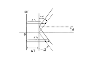
前記磁気テープを位相ロックする場合に、前記サーボパターン中にアジマス角0度のセグメントがない場合には、アジマス角が正のセグメントに対応する再生チャンネルの出力サーボパターンの周期を、所定の分周比で必要なだけ分周して第一の基準信号と位相比較するようになし、負のセグメントに対応する再生チャンネルの出力サーボパターンの周期を、同じ分周比で分周して第二の基準信号と位相比較するようになし、それぞれの位相比較器の出力をアジマス角の絶対値を考慮した演算を行って、位相ロックするようにしてもよい。第二の基準信号は第一の基準信号と実質的に同じ(周波数)場合もあり得る。一方、正のアジマス角のチャンネルの出力と負のアジマス角のチャンネルの出力が大きく異なる場合には、第1の基準信号と第2の基準信号とを同一周波数で位相の異なる信号とする。
α1, α2をサーボパターンの(既知の)アジマス角として、テープがΔTだけ走行する間に、dだけテープが上がった(相対的にヘッドが下がった)とすると、
ΔT− アジマス角α1のセグメントとREF(基準)との間の距離(又は周期)
ΔT+ アジマス角α2のセグメントとREF(基準)との間の距離(又は周期)
ΔT=(ΔT− + ΔT+)/2 + d(tanα1−tanα2)
尚、テープの変形を考慮する場合には上記α1を(α1−γ),(α1−β−γ)とし、上記α2を(α2+γ),(α2−β+γ)とすればよい(例えば図19参照)。
When the magnetic tape is phase-locked, if there is no segment with an azimuth angle of 0 degrees in the servo pattern, the period of the output servo pattern of the reproduction channel corresponding to the segment with a positive azimuth angle is divided by a predetermined frequency. Divide as many times as necessary by the ratio and compare the phase with the first reference signal, and divide the period of the output servo pattern of the playback channel corresponding to the negative segment by the same division ratio to the second The phase may be compared with the reference signal, and the output of each phase comparator may be phase-locked by performing an operation considering the absolute value of the azimuth angle. The second reference signal may be substantially the same (frequency) as the first reference signal. On the other hand, when the output of the channel of the positive azimuth angle and the output of the channel of the negative azimuth angle are greatly different, the first reference signal and the second reference signal are signals having the same frequency and different phases.
Assuming that α1 and α2 are the (known) azimuth angles of the servo pattern, and the tape has moved up by d (relatively lowering the head) while the tape traveled by ΔT,
[Delta] T - the distance between the segment and the REF of the azimuth angle [alpha] 1 (reference) (or period)
Distance (or period) between the segment of ΔT + azimuth angle α2 and REF (reference)
ΔT = (ΔT − + ΔT + ) / 2 + d (tan α1−tan α2)
When considering the deformation of the tape, α1 is set to (α1-γ), (α1-β-γ), and α2 is set to (α2 + γ), (α2-β + γ) (see, for example, FIG. 19). ).
これにより、サーボパターン中にアジマス角0度のセグメントがない場合に、磁気テープを位相ロックすることができる。 This makes it possible to lock the phase of the magnetic tape when there is no segment with an azimuth angle of 0 degrees in the servo pattern.
前記データ記録時に、上流の前記記録ヘッドにピギーバックされている再生ヘッドを使用して、前記サーボパターンを再生するようにしてもよい。 At the time of the data recording, the servo pattern may be reproduced using a reproducing head piggybacked on the upstream recording head.
これにより、上流のバンプの記録ヘッドによりデータを記録し、上流のバンプの再生ヘッドによりサーボパターンを再生することができる。 Thus, data can be recorded by the upstream bump recording head, and the servo pattern can be reproduced by the upstream bump reproducing head.
前記データ再生時に、下流の前記再生ヘッドを使用して、前記サーボパターンを再生するようにしてもよい。 At the time of data reproduction, the servo pattern may be reproduced using the downstream reproduction head.
これにより、データ再生時に、下流の再生ヘッドを使用して、サーボパターンを再生することができる。 As a result, the servo pattern can be reproduced using the downstream reproducing head during data reproduction.
前記データ記録時に、下流の前記再生ヘッドを使用して、前記サーボパターンを再生するようにしてもよい。この際、検出されたテープの傾きおよび記録ギャップと再生ギャップの長手方向の距離に応じて、ヘッドの位置決めをオフセットする。 At the time of the data recording, the servo pattern may be reproduced using the reproduction head downstream. At this time, the head positioning is offset according to the detected tape inclination and the distance between the recording gap and the reproduction gap in the longitudinal direction.
これにより、データ記録時に、下流の再生ヘッドを使用して、サーボパターンを再生することができる。 Thereby, the servo pattern can be reproduced by using the downstream reproducing head at the time of data recording.
前記データ再生時に、上流の前記記録ヘッドにピギーバックされている再生ヘッドを使用して、前記サーボパターンを再生するようにしてもよい。この際、検出されたテープの傾きおよび記録ギャップと再生ギャップの長手方向の距離に応じて、ヘッドの位置決めをオフセットする。 During the data reproduction, the servo pattern may be reproduced using a reproducing head piggybacked on the upstream recording head. At this time, the head positioning is offset according to the detected tape inclination and the distance between the recording gap and the reproduction gap in the longitudinal direction.
これにより、データ再生時に、上流の記録ヘッドにピギーバックされている再生ヘッドを使用して、サーボパターンを再生することができる。 Thereby, at the time of data reproduction, the servo pattern can be reproduced by using the reproducing head piggybacked on the upstream recording head.
前記記録ヘッド及び前記再生ヘッドの、記録及び/または再生ギャップの個々の位置の、基準の位置からの偏差の情報を該磁気テープ装置内に格納し、その情報を用いて前記記録ヘッド及び前記再生ヘッドの位置情報、磁気テープの変形情報、磁気テープの傾き情報、磁気テープ速度情報、及び/または、磁気テープの位相情報を補正する。 Information on the deviation of the recording and / or reproducing gap individual positions of the recording head and the reproducing head from a reference position is stored in the magnetic tape device, and the recording head and the reproducing are used using the information. Head position information, magnetic tape deformation information, magnetic tape tilt information, magnetic tape speed information, and / or magnetic tape phase information are corrected.
これにより、記録ヘッド及び再生ヘッドの位置情報、磁気テープの変形情報、磁気テープの傾き情報、磁気テープ速度情報、及び/または、磁気テープの位相情報を補正することができる。 Thereby, position information of the recording head and the reproducing head, deformation information of the magnetic tape, tilt information of the magnetic tape, magnetic tape speed information, and / or phase information of the magnetic tape can be corrected.
前記サーボパターンに挟まれたデータ領域の構成要素である各パス毎の領域の所定の位置に、前記データバンドおよび/またはパスの識別情報を挿入するようにしてもよい。 The data band and / or path identification information may be inserted at a predetermined position in the area for each path, which is a component of the data area sandwiched between the servo patterns.
これにより、磁気テープ装置により、データ領域の所定の位置で、データバンド及び/またはパスの識別情報を識別することができる。 As a result, the identification information of the data band and / or the path can be identified at a predetermined position in the data area by the magnetic tape device.
各パス毎に、前記サーボパターンに挟まれたデータ領域と、隣接して先行または後続するサーボパターンと、付随するガードスペースとを単位にして、その整数倍を物理ブロックとして取り扱うようにしてもよい。 For each pass, an integer multiple of the data area sandwiched between the servo patterns, the adjacent preceding or succeeding servo pattern, and the accompanying guard space may be handled as physical blocks. .
データバーストとは、データバンド上でサーボパターンとサーボパターンに挟まれた領域にある、1パスの部分データを含む。それぞれの領域には、規定のパス数(2×往復回数)のデータバーストが磁気テープ幅方向に多重化(1パス毎にトラック位置をかえて多重化)される。 The data burst includes one-pass partial data in a region sandwiched between servo patterns on the data band. In each area, data bursts of a prescribed number of passes (2 × number of reciprocations) are multiplexed in the magnetic tape width direction (multiplexed by changing track positions for each pass).
これにより、データ管理が容易となる。 This facilitates data management.
各パス毎に、前記サーボパターンに挟まれたデータ領域と、隣接して先行または後続するサーボパターンと、付随するガードスペースとを単位に、1個または複数個を用いてテープマークとなすようにしてもよい。テープマークはファイルマークを含む。テープマーク(ファイルマーク)はデータの終わりを表す。 For each pass, one or a plurality of data areas sandwiched between the servo patterns, adjacent preceding or succeeding servo patterns, and accompanying guard spaces are used as tape marks. May be. The tape mark includes a file mark. The tape mark (file mark) represents the end of data.
これにより、磁気テープを取り扱い易くなる。 This facilitates handling of the magnetic tape.
本発明に係るサーボパターン記録装置は、磁気テープに記録するサーボパターンの磁化遷移の境界の形状と同じ形状の記録ギャップを有し前記サーボパターンを前記磁気テープの全幅に亘って記録する記録ヘッドと、前記記録ヘッドで前記磁気テープ全幅を記録するに当たり、前記サーボパターン1つ当たりの記録電流の変化の回数を全て奇数回或いは全て偶数回に制御する制御手段とを具備する。磁化遷移は反転を含む。境界は磁気テープの記録面内にあり、磁化遷移(反転)は、記録電流の変化に基づいている。 A servo pattern recording apparatus according to the present invention comprises a recording head having a recording gap having the same shape as the boundary of magnetization transition of a servo pattern recorded on a magnetic tape, and recording the servo pattern over the entire width of the magnetic tape; And a control means for controlling the number of changes in the recording current per servo pattern to all odd numbers or all even numbers when recording the full width of the magnetic tape by the recording head. The magnetization transition includes inversion. The boundary is in the recording surface of the magnetic tape, and the magnetization transition (reversal) is based on the change in recording current.
本発明では、制御手段により記録電流の変化(反転を含む)の回数を全て奇数回或いは全て偶数回にして、サーボパターン全幅記録ヘッドにより、サーボパターンを磁気テープの全幅に記録することができる。 In the present invention, the servo pattern can be recorded on the full width of the magnetic tape by the servo pattern full-width recording head with the number of changes (including reversal) of the recording current all odd or even by the control means.
本発明に係るサーボパターン記録装置は、磁気テープに記録するサーボパターンの磁化遷移の境界の形状と同じ形状の記録ギャップを有し前記サーボパターンを前記磁気テープの全幅に亘って記録する磁気ヘッドと、前記記録ヘッドで前記磁気テープ上に先ず記録し、次いでデータ記録領域を形成するように後続の全幅消去ヘッドで該サーボパターンの一部を消去することで、該サーボパターンを形成する。 A servo pattern recording apparatus according to the present invention includes a magnetic head having a recording gap having the same shape as the boundary of magnetization transition of a servo pattern recorded on a magnetic tape, and recording the servo pattern over the entire width of the magnetic tape. First, recording is performed on the magnetic tape by the recording head, and then the servo pattern is formed by erasing a part of the servo pattern by the subsequent full-width erasing head so as to form a data recording area.
これにより、磁気テープの走行方向の幅(長さ)の狭いサーボパターン、または磁気テープの走行方向の長さの短いサーボパターンを形成することができる。 As a result, a servo pattern having a narrow width (length) in the running direction of the magnetic tape or a servo pattern having a short length in the running direction of the magnetic tape can be formed.
前記サーボパターンを、前記記録ヘッドで磁気テープ全幅を記録するに当たり、記録電流の変化のタイミングを変調してバイナリデータまたはユニークな同期信号を表現するようにしてもよい。磁化遷移(反転)は、記録電流の変化に基づいている。 When recording the full width of the magnetic tape with the recording head, the servo pattern may be expressed as binary data or a unique synchronization signal by modulating the change timing of the recording current. The magnetization transition (inversion) is based on a change in recording current.
これにより、記録電流の変化(反転を含む)のタイミングを変調してバイナリデータまたはユニークな同期信号を表現することができる。 As a result, binary data or a unique synchronization signal can be expressed by modulating the timing of change (including inversion) of the recording current.
前記サーボパターンを、前記記録ヘッドでテープ上に先ず記録し、次いで後続の全幅消去ヘッドでデータ記録部分を形成するように該記録されたサーボパターンの一部を消去するに当たり、記録電流の変調と後続の全幅消去ヘッドの動作タイミングを制御して、サーボパターン中にバイナリデータを表現する、或いは、ユニークな同期信号を表現するようにしてもよい。 When the servo pattern is first recorded on the tape by the recording head and then a part of the recorded servo pattern is erased so as to form a data recording portion by the subsequent full width erasing head, The operation timing of the subsequent full width erasing head may be controlled to express binary data in the servo pattern or to express a unique synchronization signal.
これにより、記録電流の変調と後続の全幅消去ヘッドの動作タイミングを制御して、サーボパターン中にバイナリデータまたはユニークな同期信号を表現することができる。 As a result, the modulation of the recording current and the operation timing of the subsequent full-width erasing head can be controlled to express binary data or a unique synchronization signal in the servo pattern.
前記サーボパターンを、1ビットのデータに対応させる、或いは、1ビットのデータまたはユニークな同期信号に対応させるようにしてもよい。 The servo pattern may correspond to 1-bit data, or may correspond to 1-bit data or a unique synchronization signal.
これにより、サーボパターンにより1ビットのデータ、或いは、1ビットのデータまたはユニークな同期信号を提供することができる。 Accordingly, 1-bit data, 1-bit data, or a unique synchronization signal can be provided by the servo pattern.
前記サーボパターンにアドレス情報を挿入する際に、該サーボパターン記録装置が扱える最長の磁気テープよりも充分に長いモジュロのアドレス発生器を用いると共に、該サーボパターン記録装置に生の磁気テープを装填する毎に、アドレス発生器のアドレスをリセットする。また、前記アドレス情報をサーボパターンに挿入する際に、アドレス情報が挿入されているサーボパターンに対して、ユニークな同期信号が挿入されているサーボパターンを先行させることにより、アドレス情報のフレーム同期を確実に出来る。 When address information is inserted into the servo pattern, a modulo address generator that is sufficiently longer than the longest magnetic tape that can be handled by the servo pattern recording device is used, and a raw magnetic tape is loaded into the servo pattern recording device. Each time the address generator address is reset. In addition, when inserting the address information into the servo pattern, the servo pattern in which the unique synchronization signal is inserted is preceded by the servo pattern in which the address information is inserted, thereby synchronizing the frame of the address information. I can do it for sure.
これにより、サーボパターンにアドレス情報を記録することができる。 Thereby, address information can be recorded on the servo pattern.
サーボパターン記録装置は、未記録の磁気テープを定速走行させるテープ走行装置と、テープに接触している記録ヘッドと、記録ヘッドに電流を供給する電子回路とで構成されている。サーボパターンの記録動作は、磁気テープを定速走行させながら記録電流を変化させる(一般にはトランジション以外の点でも電流は流れている)だけである。 The servo pattern recording device includes a tape traveling device that travels an unrecorded magnetic tape at a constant speed, a recording head that is in contact with the tape, and an electronic circuit that supplies current to the recording head. The servo pattern recording operation is merely changing the recording current while the magnetic tape is running at a constant speed (generally, the current flows at a point other than the transition).
本発明に係る記録方法は、データバンドを有する磁気テープにデータを記録する方法において、前記データバンドの全幅にわたって、且つ前記磁気テープの長手方向には間隔をあけて配置されたサーボパターンからサーボ信号を取得し、前記取得したサーボ信号に基づいて、前記サーボパターン間にガードスペースを介してデータを記録する。 The recording method according to the present invention is a method for recording data on a magnetic tape having a data band, wherein servo signals are generated from servo patterns arranged at intervals in the entire width of the data band and in the longitudinal direction of the magnetic tape. And recording data via the guard space between the servo patterns based on the acquired servo signal.
前記サーボパターンを、その磁化遷移の境界の形状と同じ形状の記録ギャップを持つサーボパターン記録ヘッドで、トランジションの数をサーボパターン1つ当たり、全て奇数回または偶数回となるようにテープ上に記録することによって、データ記録領域を形成してもよい。 The servo pattern is recorded on the tape with the servo pattern recording head having the same recording gap as the shape of the boundary of the magnetization transition so that the number of transitions is odd or even number per servo pattern. By doing so, a data recording area may be formed.
前記サーボパターンを、その磁化遷移の境界の形状と同じ形状の記録ギャップを持つサーボパターン記録ヘッドで磁気テープ上に先ず記録し、次いで該記録したサーボパターンの一部を下流にある全幅消去ヘッドで消去することによって、データ記録領域を形成してもよい。 The servo pattern is first recorded on the magnetic tape by a servo pattern recording head having a recording gap of the same shape as the boundary shape of the magnetization transition, and then a part of the recorded servo pattern is recorded by a full width erasing head downstream. The data recording area may be formed by erasing.
前記データバンド上で、前記サーボパターンを前記データバンドの幅方向に、少なくとも2つのセグメントから構成されるようになすと共に隣り合うセグメントを異なるアジマス角で記録するようになして、データ記録領域を形成してもよい。 On the data band, the servo pattern is composed of at least two segments in the width direction of the data band, and adjacent segments are recorded at different azimuth angles to form a data recording area. May be.
以上のように、本発明によれば、正確にデータを記録、再生することが可能な磁気テープ、該磁気テープのサーボパターン記録装置、及び該磁気テープの変形(幅と長手方向の伸縮)情報や磁気テープの傾き情報を検出することを可能とする磁気テープ装置、該磁気テープの製造方法及び記録方法を提供することができる。 As described above, according to the present invention, a magnetic tape capable of accurately recording and reproducing data, a servo pattern recording device for the magnetic tape, and deformation (width and longitudinal expansion / contraction) information of the magnetic tape. And a magnetic tape device capable of detecting tilt information of the magnetic tape, a method for manufacturing the magnetic tape, and a recording method can be provided.
以下、本発明の実施の形態を図面に基づき説明する。
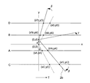
図1は本発明の一実施形態に係る磁気テープを示す平面図、図2(A)〜(D)は図1に示す磁気テープ1のサーボパターン2の例を示す平面図、図3は磁気テープ装置のヘッド位置、磁気テープ1の変形及び磁気テープ1の傾きの情報の検出の原理説明図である。
図1に示すように、磁気テープ1は、複数(例えば4個)のデータバンドb0、b1、b2及びb3と、データバンドb0、b1、b2及びb3の全幅に亘って、且つ磁気テープ1の長手方向には間隔をあけて配置されたサーボパターン2と、サーボパターン2とサーボパターン2との間に配置されデータバースト3と、サーボパターン2とデータバースト3との間に配置されたガードスペース4とを備えている。例えばサーボパターン2とデータバースト3とガードスペースとの整数倍を物理ブロックとして取り扱うようにしている。
Hereinafter, embodiments of the present invention will be described with reference to the drawings.
FIG. 1 is a plan view showing a magnetic tape according to an embodiment of the present invention, FIGS. 2A to 2D are plan views showing examples of
As shown in FIG. 1, the
データバンドb0、b1、b2及びb3は、磁気テープ1を幅方向に分割して形成された磁気テープ1全長に亘った領域である。データバンドb0、b1、b2及びb3は、それぞれ「データサブバンド×データの記録/再生を並列して行う磁気テープ装置のヘッドのチャンネルの数」で構成される。データの記録/再生は、通常1つのデータバンドを終了してから次のデータバンドに移る。
The data bands b0, b1, b2, and b3 are regions extending over the entire length of the
データサブバンドは、幅がヘッドHのチャンネルスペーシングで、磁気テープ1全長にわたった領域である。並列記録/再生する多チャンネルヘッドの対応する1チャンネルが、1パス毎に磁気テープ1の幅方向に位置を変えて、規定回数の往復(1往復=2パス)で走査を完了する領域である。
The data subband is an area extending over the entire length of the
ヘッドチャンネルスペーシングは、データの記録/再生を並列に行う多チャンネルのヘッドHの、隣り合うチャンネルそれぞれの中心線の間の距離である。必ずしも全てのチャンネルが単一のギャップライン上になくてもよい(2次元的にギャップが配置されていてもよい、或いは、ヘッドを構成する複数のヘッドブロックHB1、HB2、HB3・・・のそれぞれにチャンネルがあってもよい)。 The head channel spacing is a distance between the center lines of adjacent channels of a multi-channel head H that performs data recording / reproduction in parallel. Not all channels need to be on a single gap line (two-dimensional gaps may be arranged, or each of a plurality of head blocks HB1, HB2, HB3... Constituting the head. May have channels).
サーボパターン2は、データバンドb0、b1、b2及びb3の全幅に亘って(不連続でもよい)、且つ磁気テープ1の長手方向には間隔をあけて配置されている。なお、データバンドb0のサーボパターン2と、データバンドb1のサーボパターン2とが、磁気テープ1の長手方向でずれて(オフセットされて)配置されていてもよい。データバンドb0〜b3の番号の付け方はこれに限られない。
The
サーボパターン2は、ヘッドHを磁気テープ1の幅方向に位置制御する(トラッキングをとる)、或いは、磁気テープ1を速度制御/位相制御するのに用いる磁化反転の組み合わせである。サーボパターン2は、磁気テープ1の出荷時には予め記録されていて、個々の磁気テープ装置では書き換えない。サーボパターン2は、磁気テープ1の長手方向に例えば等間隔に配置されている。
The
データバースト3は、データバンドb0、b1、b2及びb3上でサーボパターン2とサーボパターン2に挟まれた領域にある規定のパス数(2×往復回数)の部分データを含んでいる。データバースト3のそれぞれの領域には、規定のパス数(2×往復回数)の部分データが磁気テープ1の幅方向に多重化(1パス毎にトラック位置をかえて多重化)される。
The data burst 3 includes partial data of a specified number of passes (2 × number of reciprocations) in the area sandwiched between the
ガードスペース4は、サーボパターン2とデータバースト3とを分離する領域(ギャップ)である。データ記録時に発生する、データバースト3の磁気テープの長手方向の位置が変動するのを吸収する役目を負っている。フォーマット上必ず必要である。
The guard space 4 is a region (gap) that separates the
図2(A)、図2(B)及び図2(C)に示すサーボパターン2a、2b及び2cは、いずれもデータバンドb0の幅方向に2個のセグメントで構成されている。例えばサーボパターン2aは、磁気テープ1の走行方向に直交する方向に対して所定の正負のアジマス角で形成された二つのセグメントs1、s2で形成されている。図2(A)に示すように、例えばサーボパターン2aを形成する各セグメントs1、s2のアジマス角は、データバンドb0とデータバンドb2との間の仮想の境界線Gを挟んで符号が異なっている。図2(B)に示すように、例えばサーボパターン2bを形成する各セグメントのアジマス角は、データバンドb0とデータバンドb2との間の仮想の境界線Gを挟んで符号が同じになっている。サーボパターン2aの各セグメントs1、s2の幅は、それぞれデータが記録されるデータトラックのトラックピッチの略整数倍になっている。
The
図2(C)では、サーボパターン2cを所定の長さで一旦記録し、その後、後続の消去ヘッドで部分的にサーボパターン2cの一部2c´を消去し、データ領域を形成した例を示している。
FIG. 2C shows an example in which a
図2(D)では、サーボパターン2dは、6個のセグメントから構成されている。サーボパターン2dの各セグメントの(記録)アジマス角は、絶対値の等しい正と負、及び0度の3通りに設定されている。
In FIG. 2D, the
これらの例では、サーボパターン2a、2b、2c及び2dが、磁気テープ1の幅方向に連続的に配置されているが、例えば隣合うデータバンドb0と、データバンドb2との境界等で不連続となっていてもよい。
In these examples, the
図3に示すように、サーボパターン2bが等しい正と負のアジマス角αのセグメントで構成されているときに、後述する磁気テープ装置のヘッドHのトラック幅方向(Y方向)の位置情報(ずれ量 d)、磁気テープ1の変形の情報(角度β)、及び磁気テープ1の傾き情報(角度γ)を検出する原理を説明する。ヘッドHのチャンネルA、B、C及びDが同じギャップラインGL上にあるとして、サーボパターン2bの磁化反転に反応して磁気テープ装置のヘッドHが信号を出力する時点を考える。
As shown in FIG. 3, when the
2バンプ型のヘッドHは、記録ヘッドH1の上に再生ヘッドH2が(或いはその逆)ピギーバックされているヘッドブロックHB1、HB2を2つを逆向きに合わせて、1つのヘッドHとしているもので、ヘッドブロックHB1(を構成する第一のバンプ(上流側のバンプ))に記録/再生ヘッドH1、H2、ヘッドブロックHB2(を構成する第二のバンプ(下流側のバンプ))に再生/記録(或いはこれらと逆の順序に)ヘッドH2,H1を配置し、第一のバンプの記録ヘッドH1は第二のバンプの再生ヘッドH2と、また第一のバンプの再生ヘッドH2は第二のバンプの記録ヘッドH1とトラックの位置を合わせてある。 The two-bump type head H is a single head H in which the head blocks HB1 and HB2 in which the reproducing head H2 is piggybacked on the recording head H1 (or vice versa) are aligned in the opposite direction. The recording / reproducing heads H1, H2 and the head block HB2 (second bump (downstream bump) constituting) are reproduced / reproduced on the head block HB1 (first bump (upstream bump)). The recording heads H2 and H1 are arranged (or in the reverse order), the first bump recording head H1 is the second bump reproducing head H2, and the first bump reproducing head H2 is the second bump reproducing head H2. The bump recording head H1 is aligned with the track position.
図3に示すように、LTM(走行中の磁気テープ1の幅方向の運動)により磁気テープ1が長さdだけ上がった(相対的にヘッドHが下がった)場合は、チャンネルA、Cの出力は同じ値だけ位相が進む(出力時点が早くなる)、また、チャンネルB、Dの出力は同じ値だけ位相が遅れる(出力時点が遅くなる)。
As shown in FIG. 3, when the
LTMとは、ラテラルテープモーションの略であり、磁気テープ1の走行時に発生する磁気テープ1の幅方向の運動である。狭ピッチのトラック(従って、狭トラック)のトラッキングを阻害する要因になる。サーボパターン2bを再生してヘッドHと磁気テープ1の相対位置を検出し、LTMを追尾することにより、ヘッドHをできるだけ正しいトラックの位置に置くようにする制御(トラッキングサーボ)している。
LTM is an abbreviation for lateral tape motion, and is a movement in the width direction of the
磁気テープ1が変形して(磁気テープ1の幅が広がり(正、負のセグメントのなす角が角度2β大きくなり)、長さが縮んだ例)場合は、チャンネルA、B、C及びD全ての出力の位相が遅れるが、遅れ量はチャンネルA、Bは小さく、チャンネルC、Dは大きい。
When the
磁気テープ1がY方向に対して角度γ傾いて走行した場合は、チャンネルA、Cの出力の位相は進み、チャンネルB、Dのそれは後れる。チャンネルA、B、C及びDの位相変化の方向はLTMの場合と同じであるが、その変化量はチャンネルA、Bは小さく、チャンネルC、Dは大きい。これらを図3に矢印の向きと長さで表す。このように、LTM、磁気テープ1の変形、及び、磁気テープ1の走行の傾きの影響は全て異なっている。しかし、これらが混合した場合も、次に示すように完全に分離可能である。
When the
図4は磁気テープ装置のヘッド位置、磁気テープ1の変形及び磁気テープ1の傾きの情報の検出の原理説明図である。
サーボパターン2bを有する磁気テープ1に、LTM(走行中の磁気テープ1の幅方向の運動)によるシフトd(位置決め情報)、変形によるアジマス角変化が±β(変形情報)、傾きγ(傾き情報)が複合して発生した場合を示す。シフトdはヘッドH(または磁気テープ1)の位置決め情報となる。図4に示すように、チャンネルA、B、C及びDと、正規の状態にある点線で示すサーボパターン2bとの交点を(xA,yA)、(xB,yB)、(xC,yC)、D(xD,yD)とし、シフト、変形、傾きの影響を受けた実線で示すサーボパターン2bとの交点を(x´A,yA)、(x´B,yB)、(x´C,yC)、(x´D,yD)とする。また、正規の状態にあるサーボパターン2bの頂点の座標を(0,0)、頂角を(π−2α)、すなわちアジマス角±α、シフト量をdとする。未知数(d、γ、β)のうち例えばdは以下のように求められる。
FIG. 4 is a diagram for explaining the principle of detection of information on the head position of the magnetic tape device, the deformation of the
On the

ところで、
x´A−x´B = V×t´AB = V(t´B−t´A)
x´C−x´A = V×t´CA = V(t´A−t´C)
x´D−x´B = V×t´DB = V(t´B−t´D)
ここに、
V:磁気テープ速度
t´AB,t´CA,t´DB :検出出力間の経過時間
t´A,t´B,t´C,t´D :チャンネルA〜Dの出力検出時刻
yA,yB,yC,yD :チャンネル(ヘッドH)A〜Dの磁気テープ幅方向の位置(既知 再生チャンネルの組み合わせ毎に予め決められた基準値:チャンネル情報(座標情報))
ここで、各チャンネルA〜Dのy軸方向の位置yA、yB、yC、yDとアジマス角αは既知であること、また、例えば点(x´A,yA)と(x´B,yB)とのx軸方向の距離は、対応するチャンネルA、Bの出力間の経過時間或いは時刻差(何れも測定値):t´B−t´Aに磁気テープ速度Vを乗じたものである。
by the way,
x′A−x′B = V × t′AB = V (t′B−t′A)
x′C−x′A = V × t′CA = V (t′A−t′C)
x′D−x′B = V × t′DB = V (t′B−t′D)
here,
V: Magnetic tape speed t'AB, t'CA, t'DB: Elapsed time between detection outputs t'A, t'B, t'C, t'D: Output detection times of channels A to D yA, yB , YC, yD: positions of channels (heads H) A to D in the magnetic tape width direction (reference values predetermined for each combination of known reproduction channels: channel information (coordinate information))
Here, the positions yA, yB, yC, yD and the azimuth angle α in the y-axis direction of each channel A to D are known, and for example, the points (x′A, yA) and (x′B, yB) The distance in the x-axis direction is the elapsed time or time difference between the outputs of the corresponding channels A and B (both measured values): t′B−t′A multiplied by the magnetic tape speed V.
すなわち、既知の値と計測値とから、K1、K2が求まり、その結果、dが求まる。 That is, K1 and K2 are obtained from the known value and the measured value, and as a result, d is obtained.
なお、この場合は、dを求める式の分母、分子が共にVの係数倍という形になり、Vに関係なくyとtとからdを求めることができる。β、γも求めることができる。 In this case, both the denominator and numerator of the equation for obtaining d are in the form of a coefficient multiple of V, and d can be obtained from y and t regardless of V. β and γ can also be obtained.
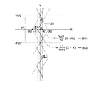
次に、サーボパターン2eを有する磁気テープ1に、LTMによるシフトd、変形によるアジマス角変化が±β、傾きγが複合して発生した場合を示す。図5に示すサーボパターン2eは、等しい正負のアジマス角±αのセグメントとアジマス角0度の2つのセグメントとで構成されている。このときに、ヘッドHのトラック幅方向の位置情報(シフトd)、及び、磁気テープ1の傾き情報(角度γ)を検出する原理を説明する(β=0とする)。
Next, a case will be described in which the
図5はヘッド位置、磁気テープ変形及び磁気テープ傾きの情報の検出の原理説明図である。
図5に示すように、ヘッドHのチャンネルA、B、C及びDが同じギャップラインGL上にあるとして、サーボパターン2eの磁化反転に反応して磁気ヘッド装置のヘッドHが信号を出力する時点を考える。
FIG. 5 is a diagram for explaining the principle of detection of information on head position, magnetic tape deformation and magnetic tape tilt.
As shown in FIG. 5, when the channels A, B, C, and D of the head H are on the same gap line GL, the head H of the magnetic head device outputs a signal in response to the magnetization reversal of the
図5に示すように、LTMによりサーボパターン2eを有する磁気テープ1が上がり(相対的にヘッドHが下がり シフトd)かつ磁気テープが(角度γ)傾いて走行した場合を示す。この場合には、チャンネルA、Cの出力は位相が進む(出力時点が早くなる)、また、チャンネルB、Dの出力は位相が遅れる(出力時点が遅くなる)。
As shown in FIG. 5, the case where the
以下に示すように、シフトd、傾き角度γを求めることができる。 As shown below, the shift d and the inclination angle γ can be obtained.
磁気テープ1が(角度γ)傾いて走行した場合(β=0と見なす)は、チャンネルC、Dの出力の位相差から直接傾きの角度γがtanγ=V(t´C−t´D)/(yD−yC)より求められる。
When the
更にチャンネルC、Dの位相差を無視すれば(要するにチャンネルA、Bの位相差のみからヘッドHの位置情報であるシフトdを求めると)、磁気テープ1の傾きも無視したこと(γ=0と見なすこと)になる。
Further, if the phase difference between the channels C and D is ignored (in short, the shift d, which is the positional information of the head H is obtained from only the phase difference between the channels A and B), the inclination of the
次に、サーボパターン2dを有する磁気テープに、LTMによるシフトd、変形によるアジマス角変化が±β、傾き角度γが複合して発生する場合を示す。サーボパターン2dが等しい正負のアジマス角のセグメント、アジマス角0度の2つのセグメント、及び、別の等しい正負のアジマス角のセグメントで構成されているときに、ヘッドHのトラック幅方向の位置情報(シフトd)、磁気テープ1の幅の情報(角度β)、及び、磁気テープ1の傾き情報(角度γ)を検出する原理を説明する。
Next, a case where a shift d due to LTM, a change in azimuth angle due to deformation, ± β, and a tilt angle γ occur in combination on the magnetic tape having the
図6及び図7はサーボパターン2dの構造、ヘッド位置、磁気テープ変形及び磁気テープ傾きの情報の検出の原理説明図である。
6 and 7 are explanatory views of the principle of detection of information on the structure of the
これらの図に示すように、磁気テープ装置のヘッドHのチャンネルA、B、C、D、E及びFが同じギャップライン上にあり、チャンネルA、B、C、D、E及びFのy軸方向の位置YA、YB、YC、YD、YE、YF及びアジマス角αは既知であるとして、サーボパターンの磁化反転に反応してヘッドHが信号を出力する時点を考える。 As shown in these figures, the channels A, B, C, D, E, and F of the head H of the magnetic tape device are on the same gap line, and the y-axis of the channels A, B, C, D, E, and F Assuming that the directional positions YA, YB, YC, YD, YE, YF and the azimuth angle α are known, consider the point in time when the head H outputs a signal in response to the magnetization reversal of the servo pattern.
次に磁気テープのシフトを計算するための計算式を説明する。 Next, a calculation formula for calculating the shift of the magnetic tape will be described.
図6に示す式(8−1)、式(8−2)は次に示すように変形することができる。 Equations (8-1) and (8-2) shown in FIG. 6 can be modified as follows.
図7に示すように、図6よりも原点を−X方向にX´シフトする(すなわち、XNEW=X+X´)。 As shown in FIG. 7, the origin is shifted by X ′ in the −X direction as compared with FIG. 6 (that is, XNEW = X + X ′).
Y0:データバンドピッチ
α:アジマス角(Y0tanα=2X0)
X1:サーボパターンを決めるシフト量、とする。
Y0: Data band pitch α: Azimuth angle (Y0tan α = 2X0)
X1: A shift amount for determining a servo pattern.
このとき、図7に示すサーボパターンの各部は、次に示すように式(11−1)、式(11−2)、式(11−3)及び式(11−4)で示される。 At this time, each part of the servo pattern shown in FIG. 7 is represented by Expression (11-1), Expression (11-2), Expression (11-3), and Expression (11-4) as shown below.
角度β(磁気テープが幅方向の広がるときの変化角度)を考慮して、アジマス角αをα−βに置き換えると、次に示す式(11−1´)、式(11−2´)、式(11−3´)及び式(11−4´)が得られる。 Considering the angle β (change angle when the magnetic tape spreads in the width direction), when the azimuth angle α is replaced with α-β, the following equations (11-1 ′), (11-2 ′), Expressions (11-3 ′) and (11-4 ′) are obtained.
角度γ(磁気テープ走行時の傾きの角度)を考慮すると、次に示す式(12−1)、式(12−2)が得られる。 Considering the angle γ (the angle of inclination during running of the magnetic tape), the following equations (12-1) and (12-2) are obtained.
また、点(X(ツーダッシュ),0)が(X(スリーダッシュ),Y(スリーダッシュ))に移動し、式(12−1)、式(12−2)は、それぞれ式(12−3)、式(12−4)となる。但し、X(ツーダッシュ)=2X0−X1、2X0=Y0tanαである。 In addition, the point (X (two dash), 0) moves to (X (three dash), Y (three dash)), and the expressions (12-1) and (12-2) are converted into the expressions (12- 3) and Equation (12-4). However, X (two dash) = 2X0−X1, 2X0 = Y0tanα.
式(12−1)〜式(12−4)を基にシフトdを考慮すると、次に示す式(13−1)、式(13−2)、式(13−3)及び式(13−4)が得られる。 Considering the shift d based on the formulas (12-1) to (12-4), the following formulas (13-1), (13-2), (13-3), and (13- 4) is obtained.
ここで、ヘッドHのチャンネルA,B,C,DのY方向の位置をYA,YB,YC,YDとすると、次に示す式(13−1´)、式(13−2´)、式(13−3´)及び式(13−4´)が得られる。これらの式から、次に示す式(13−5´)及び式(13−6´)が得られる。 Here, assuming that the positions in the Y direction of the channels A, B, C, and D of the head H are YA, YB, YC, and YD, the following expressions (13-1 ′), (13-2 ′), and (13-3 ′) and Equation (13-4 ′) are obtained. From these equations, the following equations (13-5 ′) and (13-6 ′) are obtained.
これらの式から次に示すシフトdを求める式(13−7)が得られる。 From these equations, the following equation (13-7) for obtaining the shift d is obtained.
ここで、YA、YBは既知、XA−XBは計測値(チャンネルA,B出力の時間差)から求められる。従って、K1及びK2が式(13−5´)及び式(13−6´)から求められれば、式(13−7)を用いてシフトdを求めることができる。 Here, YA and YB are known, and XA−XB is obtained from the measured value (the time difference between the channel A and B outputs). Therefore, if K1 and K2 are obtained from the equations (13-5 ′) and (13-6 ′), the shift d can be obtained using the equation (13-7).
このようにチャンネルA、B、C及びDの出力の経過時間或いは時刻差からシフトdを求めると式(13−7)を得るが、傾き角γが未知である。そこでチャンネルE、Fの出力の時間差から傾き角γを求めればシフトdが得られる。なお、この過程で用いるX軸方向の長さX1(サーボパターンのフォーマットの一部)は、サーボパターン計測時の磁気テープ速度を用いて、磁気テープの長手方向の変形を含めて補正をする必要がある。磁気テープの長手方向の変形は磁気テープ速度偏差に帰着する。 Thus, when the shift d is obtained from the elapsed time or the time difference of the outputs of the channels A, B, C, and D, the equation (13-7) is obtained, but the inclination angle γ is unknown. Therefore, the shift d is obtained by obtaining the inclination angle γ from the time difference between the outputs of the channels E and F. The length X1 in the X-axis direction (part of the servo pattern format) used in this process needs to be corrected including the deformation in the longitudinal direction of the magnetic tape using the magnetic tape speed at the time of servo pattern measurement. There is. The longitudinal deformation of the magnetic tape results in a magnetic tape speed deviation.
ところで、
X(スリーダッシュ)=X(ツーダッシュ)cosγ
Y(スリーダッシュ)=X(ツーダッシュ)sinγ
X(ツーダッシュ)=Y0・tanα−X1
一方、
tanγ=(XE−XF)/(YF−YE)
γ=tan−1[(XE−XF)/(YF−YE)] (13−8)
ここで、YF,YEは、既知であり、XE−XFは計測値から得られる。これらを式(13−5´)、式(13−6´)に代入すれば、次の式(14−1)、式(14−2)に示すように、K1、K2が全て既知の値、或いは計測値から求められた値によって、表現された。
by the way,
X (three dash) = X (two dash) cosγ
Y (three dash) = X (two dash) sinγ
X (two dash) = Y0 · tan α−X1
on the other hand,
tan γ = (XE−XF) / (YF−YE)
γ = tan −1 [(XE−XF) / (YF−YE)] (13-8)
Here, YF and YE are known, and XE-XF is obtained from the measured values. If these are substituted into the formula (13-5 ′) and the formula (13-6 ′), as shown in the following formula (14-1) and formula (14-2), all of K1 and K2 are known values. Alternatively, it is expressed by a value obtained from a measured value.
従って、式(14−1)、式(14−2)を式(13−7)に代入してシフトdを求めることができる。例えば式(13−5´)などを用いて角度βも求めることができる。 Therefore, the shift d can be obtained by substituting the equations (14-1) and (14-2) into the equation (13-7). For example, the angle β can also be obtained using the equation (13-5 ′).
磁気テープ速度の検出
磁気テープ装置により、基本的にはサーボパターンの周期を計測する。図6,9に示すサーボパターン2dように、サーボパターン中にアジマス角0度のセグメントがある場合は、単純にこのセグメントの例えば第一のトランジション(遷移)から磁気テープの長手方向次のサーボパターンの中の第一のトランジション(遷移)の周期を計測すればよい。
Magnetic tape speed detection The magnetic tape device basically measures the servo pattern cycle. When there is a segment with an azimuth angle of 0 degrees in the servo pattern as shown in FIGS. 6 and 9, for example, the first servo pattern in the longitudinal direction of the magnetic tape from the first transition of this segment is simply used. What is necessary is just to measure the period of the 1st transition (transition) in.
一方、図4に示すサーボパターン2bように、サーボパターン中にアジマス角0度のセグメントがない場合は、アジマス角が正のセグメントと負のセグメメント(例えばチャンネルAとBと)の、例えば第一のトランジション(遷移)間の周期をそれぞれ計測してその平均から磁気テープ速度を求めればLTMの変動(シフトdの変動)の影響を軽減できる。なお、データバンドの中央を挟んで上下にあるセグメントの周期をそれぞれ計測しその平均を取る方法はアジマス角0度のセグメントの場合にも使用可能で、この場合は磁気テープの傾きの影響を軽減できる。
On the other hand, when there is no segment having an azimuth angle of 0 degrees in the servo pattern as in the
このように本実施形態によれば、磁気テープ1の幅方向に複数設けられるデータバンドb0〜b3上に、サーボパターン2、ガードスペース4、データバースト3、ガードスペース4、サーボパターン2、ガードスペース4、データバースト3、・・・のように配置されている。
As described above, according to the present embodiment, the
データバースト3にデータを記録するには、サーボパターン2は予め記録されているものとして、記録開始時に先ず上流側の記録ヘッドH1と同じバンプにある再生ヘッドH2で、サーボパターン2を通常複数個再生し(この間記録電流は流さない)ヘッドHの位置を制御した後に、上流側の記録ヘッドH1に記録電流を流してデータを記録し、次にある時間経過後(次のサーボパターンの直前で)に記録電流を止める。再び同じバンプの再生ヘッドH2で次のサーボパターン2を再生し、ヘッド位置情報を検出し、直後に再びデータバースト記録に入る。以下、この記録と再生とヘッド位置制御とを記録終了まで繰り返す。記録中には下流にあるバンプの再生ヘッドH2を用いてリードアフターライト(またはリードホワイルライトと言う)を行う。
In order to record data in the data burst 3, it is assumed that the
すなわち、上流と下流との(異なるバンプの)記録ヘッドH1と再生ヘッドH2とを用いる場合に磁気テープ1の走行方向が傾くことにより記録データトラックの位置がずれる問題が生じるのに対して、本発明では、同じ上流側のバンプの記録ヘッドH1と再生ヘッドH2とを時分割で交互に使用することにより、記録ヘッドH1により近い再生ヘッドH2によりサーボパターン2を再生し正確なサーボ情報に基づきヘッドHの位置をより正確に制御し、ヘッドHを最適な位置へ誘導し、正確な位置にデータを記録することができる。また、記録時に、記録ヘッドH1から再生ヘッドH2へのクロストークの問題を解決することができる。
That is, when the upstream and downstream (different bumps) recording heads H1 and reproducing heads H2 are used, there is a problem that the recording data track position is shifted due to the inclination of the traveling direction of the
図8は、従来の磁気テープ装置のヘッド及び従来の磁気テープの部分平面図である。
つまり、従来では、図8に示したように、2バンプ型のヘッドH´は、記録ヘッドH1の上に再生ヘッドH2が(或いはその逆)ピギーバックされているヘッドブロックHB1´、HB2´を2つを逆向きに合わせて、1つのヘッドH´としているもので、ヘッドブロックHB1´(を構成する第一のバンプ(上流側のバンプ))に記録/再生ヘッドH1、H2、ヘッドブロックHB2´(を構成する第二のバンプ(下流側のバンプ))に再生/記録(或いはこれらと逆の順序に)ヘッドH2,H1を配置し、第一のバンプの記録ヘッドH1は第二のバンプの再生ヘッドH2と、また第一のバンプの再生ヘッドH2は第二のバンプの記録ヘッドH1とトラックの位置を合わせてある。再生ギャップ上には、サーボ用のギャップが形成されている。
FIG. 8 is a partial plan view of a conventional magnetic tape apparatus head and a conventional magnetic tape.
That is, conventionally, as shown in FIG. 8, the two-bump type head H ′ includes head blocks HB1 ′ and HB2 ′ in which the reproducing head H2 is piggybacked on the recording head H1 (or vice versa). The two heads H ′ are aligned in the opposite direction, and the head block HB1 ′ (the first bump (upstream bump) constituting the recording head) is formed on the recording / reproducing heads H1, H2, and the head block HB2. ′ (The second bump constituting the (downstream bump)) heads H2 and H1 are arranged for reproduction / recording (or in the reverse order), and the first bump recording head H1 is the second bump. The reproducing head H2 of the first bump and the reproducing head H2 of the first bump are aligned with the recording head H1 of the second bump. A servo gap is formed on the reproduction gap.
こうして例えば記録ギャップ(上流側)と再生ギャップ(下流側)とを1ミリメートル前後離すことにより、記録ヘッドH1から再生ヘッドH2へのクロストークを軽減している。 Thus, for example, by separating the recording gap (upstream side) and the reproducing gap (downstream side) by about 1 millimeter, crosstalk from the recording head H1 to the reproducing head H2 is reduced.
図8に示すように、従来では、磁気テープ1Aを幅方向に複数(例えば4)に分割して、それぞれに磁気テープ1Aの幅方向にデータバンド3Aとサーボバンド2Aとを設ける。記録時には、記録ヘッドH1と同じバンプにある再生ヘッドH2は、データチャンネルの外側にあるサーボ用チャンネルSと言えども、記録ヘッドH1からのクロストークによりサーボ信号の再生には使用できない。従って、磁気テープ1Aの走行方向下流にある隣のバンプの再生ヘッドH2のサーボチャンネルで、サーボ信号を検出して、記録ヘッドの位置の制御をすることになる。この状態で磁気テープ1Aの走行が傾くと、記録ヘッドH1の位置は、その分正しい位置から外れることになり、トラック密度を制約することになる。通常の方法では、磁気テープ1Aの走行の傾きの影響を軽減するには、ヘッドブロックHB1´のギャップラインとヘッドブロックHB2´のギャップラインとの間の距離を近づけることになるが、クロストークの制約などがあり難しい。
As shown in FIG. 8, conventionally, the
即ち、トラッキング動作は常に再生ギャップを基準のトラックセンターに位置合わせしようとする。従って、図9に示すように磁気テープがヘッドの前面を走行する方向(傾き)がダイナミックに変化(テープが蛇行)したときには、記録ギャップの位置は傾き角の正接と両ギャップ間の(長手方向の)距離に応じた量だけトラックずれ(トラックミスレジストレーション)を起こしてしまう。すなわち、記録トラックの位置がオフセットしたために、記録済みの隣接トラックの一部を上書きし、そのトラック幅を狭めることによりトラッキングマージンを削ることになる。 That is, the tracking operation always tries to align the reproduction gap with the reference track center. Therefore, as shown in FIG. 9, when the direction (inclination) in which the magnetic tape runs in front of the head changes dynamically (tape meandering), the position of the recording gap is between the tangent of the inclination angle and the gap (longitudinal direction). Track deviation (track misregistration) by an amount corresponding to the distance. That is, because the position of the recording track is offset, a part of the recorded adjacent track is overwritten, and the tracking margin is reduced by narrowing the track width.
これに対して、本実施形態では、図3に示すように、同じ上流側のバンプの記録ヘッドH1と再生ヘッドH2とを時分割で交互に使用することにより、記録ヘッドH1により近い再生ヘッドH2によりサーボパターン2を再生し正確なサーボ情報に基づきヘッドHの位置をより正確に制御し、ヘッドHを最適な位置へ誘導し、正確な位置にデータを記録することができる。また、記録時に、記録ヘッドH1から再生ヘッドH2へのクロストークの問題を解決することができる。
In contrast, in the present embodiment, as shown in FIG. 3, the recording head H1 and the reproducing head H2 of the same upstream bump are alternately used in a time division manner, thereby reproducing the reproducing head H2 closer to the recording head H1. Thus, the
再生時にはデータ再生に用いる再生ヘッドH2(通常は下流側バンプ)でサーボパターン2も再生してヘッドHの位置を制御する。
During reproduction, the
サーボパターン2bを有する磁気テープ1に、LTM(走行中の磁気テープ1の幅方向の運動)によるシフトd、変形によるアジマス角変化が±β、傾き角度γが複合して発生した場合に、図5に示すように、既知の値と計測値とから、K1、K2が求まり、その結果、シフトd、角度β及び傾き角度γを求めることができる。(記録ヘッドH1または再生ヘッドH2のトラック幅方向の位置決め情報(シフトd)を、磁気テープ1の変形情報(角度β)、及び/または、傾き情報(角度γ)を用いて補正する(求める)ことができる。)その結果、ヘッドHの位置を調整することで、データの正確な記録、再生を行うことができる。
When the
サーボパターン2eを有する磁気テープ1に、LTMによるシフトd、傾き角度γが複合して発生した場合には、チャンネルC、Dの出力の位相差から直接傾きの角度γが求まり、[数2]に示す式からシフトdを求めることができる。その結果、ヘッドHの位置を調整することで、データの正確な記録、再生を行うことができる。
When the
サーボパターン2dを有する磁気テープに、LTMによるシフトd、変形によるアジマス角変化が±β、傾き角度γが複合して発生する場合に、式(13−7)からシフトdが求まり、式(13−8)からγを求めることができる。その結果、ヘッドHの位置を調整することで、データの正確な記録、再生を行うことができる。
When the shift d due to LTM, the azimuth angle change due to deformation occurs ± β, and the tilt angle γ in combination with the magnetic tape having the
マルチチャンネルヘッドHを備えたリニア型磁気テープ装置により、サーボパターン2を有する磁気テープ1を記録、再生することで、通常の磁気テープ1の幅方向の位置情報に加え、磁気テープ1の変形やヘッドHの傾きに起因する偏差にも対応した位置決め情報の検出することができ、トラック密度(TPI)を飛躍的に高めることができる。
By recording and reproducing the
これまではトラックピッチが限りなく狭いとしていたが、以下では磁気テープの一実施例を示す。
図10は一実施例のサーボパターンとデータバンドとの位置関係及びヘッドチャンネル位置とパスとの関係を示す図である。
In the past, the track pitch was supposed to be as narrow as possible, but an example of a magnetic tape will be shown below.
FIG. 10 is a diagram illustrating the positional relationship between the servo pattern and the data band and the relationship between the head channel position and the path according to one embodiment.
図10に示すように、データバンドの幅方向のピッチであるデータバンドピッチが640マイクロメートル、16トラック並列記録/再生、1つのデータバンドを16パス(8往復)で完結するもの(トラックピッチは2.5マイクロメートル)、また、LTMは±15マイクロメートル以下、更に、ヘッドはサーボを考慮して17チャンネル(チャンネル17(CH17):サーボ用補助チャンネル)としておくが、これに限ったものではない。 As shown in FIG. 10, the data band pitch that is the pitch in the width direction of the data band is 640 micrometers, 16 track parallel recording / reproduction, and one data band is completed in 16 passes (8 reciprocations) (track pitch is 2.5 micrometers), LTM is ± 15 micrometers or less, and the head is set to 17 channels (channel 17 (CH17): auxiliary servo channel) in consideration of servo, but it is not limited to this. Absent.
サーボパターンを挿入する頻度は、サンプリングの立場からは高いほうがよいのは当然であるが、冗長度の観点と、ヘッドの位置情報、磁気テープ幅情報、及び、磁気テープの傾き情報の検出感度と、更には想定されるLTMとを考慮して、頻度とサーボパターンの最適な組み合わせを探す必要がある。 The frequency of inserting the servo pattern is naturally better from the standpoint of sampling, but the viewpoint of redundancy and the detection sensitivity of head position information, magnetic tape width information, and magnetic tape tilt information In addition, it is necessary to search for an optimal combination of frequency and servo pattern in consideration of the assumed LTM.
以下、サーボパターンはこれまでに挙げた中で最も複雑且つ長手方向の専有長が短い(冗長度が低くなる)図7に示す例を用いて説明するが、他のパターンの場合も同様である。 Hereinafter, the servo pattern will be described with reference to the example shown in FIG. 7 which is the most complicated and has the shortest exclusive length in the longitudinal direction (redundancy is low), but the same applies to other patterns. .
サーボパターンは、正負のアジマス角のセグメントの幅をそれぞれ80マイクロメートル、アジマス角0度のセグメントの幅をそれぞれ200マイクロメートルとする。なお、通常サーボパターンは複数の磁化反転で構成されるが、ここではその中の1つの磁化反転を記してある。サーボパターンとデータバンドのテープ幅方向の位置はパス1の時18.75(トラック上端で20)マイクロメートル、オフセットさせる。通常、奇数のパスはBOTからEOTに、偶数のパスはEOTからBOTにテープは走行する。各チャンネルは、全16パス(8往復)でデータサブバンドを構成する。奇数の8パスと偶数の8パスは別々のトラックグループを形成し、行き帰りのパスによるトラックが隣り合うことをできるだけ避ける。この例では、隣のチャンネルのパス16とパス1のトラック、パス15とパス2のトラック、及びパス16と隣のチャンネルのパス1のトラックが該当する。データバースト3の所定の位置に、データに加えて、データバンド及びパスの識別情報を挿入してもよい。なお、ガードバンドを設ける場合にはこれらの(テープ走行方向が逆向きになる)トラック間に入れる。(なお、一般にガードバンドは、データバンドとデータバンドを、或いは、トラックとトラックを分離する領域である。データバンドは、フォーマット上は必ずしも必要ではない。)各パスにおけるヘッドチャンネルと図7のチャンネルの対応は、A:CH10、B:CH8、C:CH17、D:CH1、E:CH14、F: CH4となる。CH1からCH1はデータチャンネルでCH17はサーボ用の補助チャンネルである。オフセットをとったことにより式(13−7)におけるdの値は、Nをパスナンバーとして:
d=dN+LTM
dN=−18.75+{2.5×(N−1)/2}
N=1,3,5,...,15(BOT→EOT)
dN={2.5×(N−1)/2}
N=2,4,6,...,16(EOT → BOT)
となる。
In the servo pattern, the positive and negative azimuth angle segments each have a width of 80 micrometers, and the width of the segment having an azimuth angle of 0 degrees is 200 micrometers. Note that the normal servo pattern is composed of a plurality of magnetization reversals, but one magnetization reversal is shown here. The positions of the servo pattern and the data band in the tape width direction are offset by 18.75 micrometers (20 at the upper end of the track) in
d = dN + LTM
dN = −18.75 + {2.5 × (N−1) / 2}
N = 1, 3, 5,..., 15 (BOT → EOT)
dN = {2.5 × (N−1) / 2}
N = 2, 4, 6, ..., 16 (EOT → BOT)
It becomes.
また、YA,YBはトラックセンターで:
YA=−40
YB=+40
(単位:マイクロメートル)である(CH9のトラックセンターを基準にして)。
YA and YB are track centers:
YA = -40
YB = + 40
(Unit: micrometer) (based on CH9 track center).
同様に、
YC=−320
YD=+320
YE=−200
YF=+200
(単位:マイクロメートル)である。
Similarly,
YC = −320
YD = + 320
YE = -200
YF = + 200
(Unit: micrometer).
オフセットをとることより、何れのパスにおいても、想定されている±15マイクロメートルのLTMに対して、ヘッドがそれぞれのセグメントを外れることはない。また、Nの奇数、偶数とデータバンドナンバーの組み合わせとでサーボパターンの向き(磁気テープ走行方向に対して)が逆になる。 By taking the offset, the head does not deviate from the respective segment for any expected path of ± 15 micrometer LTM. Further, the servo pattern direction (relative to the magnetic tape running direction) is reversed depending on the combination of odd and even numbers of N and the data band number.
さて、データサブバンドの幅(ヘッドのチャンネルスペーシング)が決まっている場合に、アジマス角及び磁化反転の間隔と数を決めるには、次のことを考慮する。LTMの検出感度、例えば1マイクロメートルのLTMを何マイクロメートルの長手方向の位置の変化(時間として検出)に変換したいか。想定される最大のLTMのときにも、アジマス角故に隣の同極性の磁化反転により誤検出されることはないか。必要最小限の数の磁化反転とデータバーストの長さで決まる冗長度及びサンプリング周期は必要十分か(周波数に換算して、必要とされるサーボ帯域の10倍程度)。LTMの検出感度を上げるためにアジマス角を大きくすることと、他の条件は相反しているので妥協点を探ることになる。 Now, in order to determine the azimuth angle and the interval and the number of magnetization reversals when the data subband width (head channel spacing) is determined, the following is considered. LTM detection sensitivity, for example, how many micrometers of LTM you want to convert to a change in longitudinal position (detected as time). Even in the case of the maximum expected LTM, because of the azimuth angle, isn't it erroneously detected by the adjacent magnetization reversal of the same polarity? Are the redundancy and sampling period determined by the minimum number of magnetization reversals and the length of the data burst necessary and sufficient (converted to frequency, about 10 times the required servo bandwidth)? In order to increase the detection sensitivity of LTM, increasing the azimuth angle and other conditions are contradictory, so a compromise point will be searched.
この一例として正負のアジマス角を約±14度(tanα=0.25)とする。この結果、図7のX1は70マイクロメートルとなる。また隣り合うサーボパターンの間隔を1ミリメートルとする。従って、磁気テープ速度を10メートル/秒とすればLTMをサンプリングする周波数は10KHzとなる。また、1マイクロメートルLTMは正負のアジマス角のおかげで長手方向に0.5マイクロメートルの長さに変換される。これは磁気テープ速度10メートル/秒においては50ナノ秒(5E−8秒)の時間に相当する。クロック1GHzのカウンターで計時すれば0.1マイクロメートル程度のLTMが検出可能となる(約5カウントの差となる)。トラックピッチ2.5マイクロメートルに対して十分な分解能である。因みに、この時磁気テープの傾き及び磁気テープの変形の検出感度は5カウントの差(長手方向に約5ナノメートルの変化/変形に相当)を目安にすると、傾き(角度γ)約7E−3度及び変形(角度β)約8.5E−3度となる。なお、アナログ回路の助けを借りれば、より低い周波数のクロックを用いつつ、サブナノ秒の分解能で時間を計測できることも知られている。 As an example of this, the positive and negative azimuth angles are about ± 14 degrees (tan α = 0.25). As a result, X1 in FIG. 7 is 70 micrometers. The interval between adjacent servo patterns is 1 mm. Therefore, if the magnetic tape speed is 10 meters / second, the frequency at which LTM is sampled is 10 KHz. Also, 1 micrometer LTM is converted to a length of 0.5 micrometers in the longitudinal direction thanks to positive and negative azimuth angles. This corresponds to a time of 50 nanoseconds (5E-8 seconds) at a magnetic tape speed of 10 meters / second. If the time is measured with a 1 GHz clock counter, an LTM of about 0.1 micrometers can be detected (a difference of about 5 counts). The resolution is sufficient for a track pitch of 2.5 micrometers. Incidentally, at this time, when the inclination of the magnetic tape and the detection sensitivity of the deformation of the magnetic tape are set to a difference of 5 counts (corresponding to a change / deformation of about 5 nanometers in the longitudinal direction), the inclination (angle γ) is about 7E-3. Degree and deformation (angle β) is about 8.5E-3 degrees. It is also known that with the help of an analog circuit, time can be measured with sub-nanosecond resolution while using a lower frequency clock.
この時のデータバースト3の長さは、サーボパターン(トランジション)の間隔を10マイクロメートルで4トランジションとし、サーボパターンの前後のガードスペース4をそれぞれ80マイクロメートル程度とすると、全部で約800マイクロメートルの長さとなる。すなわち、磁気テープ1の長手方向の利用効率は約80パーセントとなる。
The length of the data burst 3 at this time is about 800 μm in total, assuming that the interval of the servo pattern (transition) is 4 transitions at 10 μm and the guard space 4 before and after the servo pattern is about 80 μm. It becomes the length. That is, the utilization efficiency in the longitudinal direction of the
なお、4トランジションのサーボパターンは、第2のトランジションを第1のトランジションに近づけたり、第3のトランジションを第1のトランジションから遠ざけたり位置(位相)変調することにより(同極性のトランジション、第1と第3または第2と第4、の距離を20マイクロメートルより近づけないように変調している)、フレーム同期のためのユニークなパターンと1ビットのデータを表現することができる(多値で変調すれば複数ビットのデータも表現することが可能となる)。すなわち、サーボパターン2を、その磁化遷移の境界の形状と同じ形状の後述する記録ギャップ309(図17参照)を持つ記録ヘッド308(サーボパターン全幅記録ヘッド)で磁気テープ1全幅を記録するに当たり、記録電流の変化のタイミングを変調して異なるサーボパターンを形成し、バイナリデータ、ユニークな同期信号を表現しうる。更に、複数のサーボパターンを用いて、ユニークな同期信号と複数のデータビットからなるデータフレームを構成することができる。図2(C)に示すサーボパターン2cを形成するときに、記録電流の変化のタイミングを変調して複数のサーボパターンを形成し、バイナリデータ、ユニークな同期信号を得るようにしてもよい。
The servo pattern of 4 transitions is obtained by making the second transition closer to the first transition, or moving the third transition away from the first transition, or by position (phase) modulation (transition having the same polarity, first transition). And the third or second and fourth distances are modulated so as not to be closer than 20 micrometers), a unique pattern for frame synchronization and 1-bit data can be expressed (multi-valued) If modulated, it is possible to express multi-bit data). That is, when recording the
以上を基に磁気テープ装置のトラッキングサーボ構成の一例を示す。
図11は磁気テープ装置のトラッキングサーボ機構のブロック図である。
磁気テープ装置の信号処理系、リールモーター制御系及びサーボパターンのデータ復調系は公知の手法を用いることができる。
An example of the tracking servo configuration of the magnetic tape device is shown based on the above.
FIG. 11 is a block diagram of the tracking servo mechanism of the magnetic tape device.
Known methods can be used for the signal processing system, reel motor control system, and servo pattern data demodulation system of the magnetic tape device.
トラッキングサーボ機構100は、ヘッドスタック101、AMP/SEL(プリアンプ/セレクター)102、ピーク検出/時間計測(距離換算)器103、データバーストゲート104、フライホィール105、トラッキング(LTM)検出器106、D/A(ディジタル/アナログ変換)器107、微動アクチュエーター108、粗動アクチュエーター109を備えている。
The tracking
AMP/SEL(プリアンプ/セレクター)102のSELはR/W(リード/ライト)に応じて対応するバンプからの出力を選択する。 The SEL of the AMP / SEL (preamplifier / selector) 102 selects the output from the corresponding bump according to R / W (read / write).
ピーク検出/時間計測(距離換算)器103は、データバンドセレクトのLSB(テープ走行方向)とパスナンバーNのLSBの情報に従って、チャンネルA,B,C,D,E及びFに対応するチャンネルのピーク検出と時間計測を行い、速度情報を用いて長手方向の距離に換算する。
The peak detection / time measurement (distance conversion)
データバーストゲート104はフライホィール105の出力を受けて、各データチャンネル(CH1,CH2,...,CH16)に対して時間軸上でサーボパターンをマスクする。なお、図示しないが、記録側にもサーボパターンを保護するために、同じくフライホィール105の出力を受けて、記録電流をゲートする機能ブロックが挿入されている。
The data burst
フライホィール105はキャプチャーモードとロックモードで時定数の異なる公知のPLL(位相同期系)である。
The
トラッキング(LTM)検出器106はピーク検出/時間計測(距離換算)器103の出力を受けてシフトdを計算し、パスナンバーの情報を用いてトラッキングエラー(LTM)を求める。サーボループは、この値をゼロに近づけるように働く。ピーク検出/時間計測(距離換算)器103の他の出力は、磁気テープ速度を検出(パルス列の周期を速度情報に変換)してリールモーターの制御に用いられるが、公知の技術であるのでここでは立ち入らない。
The tracking (LTM)
微動アクチュエーター108及び粗動アクチュエーター109は、例えばスプリングで保持さているヘッドHをムービングコイルで駆動するステージ及びパスナンバーの情報とデータバンド指定の情報とに基づいてステージを駆動するパルスモーターとスクリュー等である。なお、これらはストロークの長いリニアモーターで構成することもできる。微動アクチュエーター108及び粗動アクチュエーター109は、公知の技術である。
The
次に本発明のピーク検出/時間計測(距離換算)器103とトラッキング(LTM)検出器106の構成の一例を示す(他のブロックは公知の技術で実現できる)。
Next, an example of the configuration of the peak detection / time measurement (distance conversion)
図12はトラッキングサーボ機構のピーク検出/時間計測(距離換算)器103の詳細を示すブロック図である。ここでは時間の計測に内蔵時計を用いた例を示す。
ピーク検出/時間計測(距離換算)器103は、ピーク検出器131、時刻サンプラー132、距離検出器133、内蔵時計134、パルス成形器135を備えている。
FIG. 12 is a block diagram showing details of the peak detection / time measurement (distance conversion)
The peak detection / time measurement (distance conversion)
ピーク検出器131は、ローパスフィルター、狭義のピーク検出器(正負のピークを別々に検出)、及びセレクターで構成され、正負の検出ピークの何れかを選択して出力する。ローパスフィルターの役割はデータバースト及びノイズを減衰させて、サーボパターンの誤検出を防ぐことにある。
The
時刻サンプラー132は、内蔵時計134の出力をピーク検出器131の出力でサンプリングして時刻を得る。
The
距離検出器133は、時刻サンプラー132の出力間の差を取り、磁気テープ速度を乗じて距離に変換し、さらにパスナンバー情報(すなわちテープ走行方向情報)とデータバンド情報に従って、その符号を反転させる。
The
内蔵時計134はカウンターで、サーボパターンの同極性トランジション間の時間の2倍より長い周期があればよい(2つの時刻入力の大小関係からトランジション間の正負の時間が必要)。この例では、クロック1GHzの13ビットのカウンターが適当である。何故ならば、このカウンターの出力の周期は8マイクロ秒強であるのに対して、同極性のトランジションの間隔20マイクロメートルは、磁気テープ速度10メートル/秒の時2マイクロ秒に相当している。 The built-in clock 134 is a counter and only needs to have a cycle longer than twice the time between the same-polarity transitions of the servo pattern (a positive / negative time between transitions is necessary due to the magnitude relationship between the two time inputs). In this example, a 13-bit counter with a clock of 1 GHz is appropriate. This is because the output period of this counter is just over 8 microseconds, whereas the 20-micrometer interval between the same polarity transitions corresponds to 2 microseconds at a magnetic tape speed of 10 meters / second. .
パルス成形器135の一例にはパルス幅Tがトランジションの間隔よりも長いリトリガーモノマルチバイブレーター(この例では間隔2マイクロ秒、すなわち2<T<<100)が挙げられる。
An example of the
図13はトラッキングサーボ機構のトラッキング(LTM)検出器106の詳細を示すブロック図である。
FIG. 13 is a block diagram showing details of the tracking (LTM)
トラッキング(LTM)検出器106は、cosγ,sinγ演算器61、K1演算器62、K2演算器62´、d演算器63、LTM演算器64及びdN演算器65を備えている。
The tracking (LTM)
cosγ,sinγ演算器61は、先ず距離検出器133からの±(XE-XF)と既知のYF,YEからγを求め(γの値は小さいからリニアの近似でよい)、次いでcosγ,sinγを求める(こちらは他の定数との関係から級数展開して第2項までの近似が適当)。
The cos γ,
K1演算器62、K2演算器62´は、それぞれ距離検出器133からの±(XA-XD),±(XB-XC)とcosγ,sinγ演算器61からのcosγ,sinγとを受け、既知のY0(データバンドピッチ),tanα(=0.25),X1(=70),YA, YD, YB, YCを用いてK1,K2を計算(四則演算)する。
The
d演算器63は、距離検出器133からの±(XA-XB)とK1演算器62、K2演算器62´からのK1,K2とを受け、既知のYA,YBと合わせて式(13−7)に従ってシフトdを計算(四則演算)する。
The
LTM演算器64は、d演算器63の出力dとdN演算器65の出力dNの差をとってLTMを求める。
The
dN演算器65は、パスナンバーNをdNに変換する(テーブルルックアップが簡単)。なお、この例ではパスナンバーN(N=1,2,...,16)のLSB(最下位ビット)がテープ走行方向を表している。
The
図14は、別のトラッキング(LTM)検出器106´の詳細を示すブロック図である。
トラッキング(LTM)検出器106´は、LTM演算器64、dN演算器65に加えて、γ演算器61´及びd演算器63´を備えている。
FIG. 14 is a block diagram illustrating details of another tracking (LTM)
The tracking (LTM)
γ演算器61´は、γの近似(リニア近似)を演算する。
The
γ演算器61´及びd演算器63´を用いた近似解を求める計算の一例を説明する。d演算器は式(22-1)の演算を行いdを得る。
An example of calculation for obtaining an approximate solution using the
磁気テープ速度を変えた場合、例えば5メートル/秒にした場合、周波数は1/2倍に、時間は2倍になる。この際、ローパスフィルターのカットオフ周波数も1/2にすることが望ましい。一方、時間の計測は、クロック周波数を1/2にしてカウント数を維持する。或いは、クロック周波数を維持してカウント数を2倍にする等も考えられる。他の速度にした場合も、速度に比例してローパスフィルターのカットオフ周波数と時間計測方法とを変更すればよいのは言うまでもない。 If the magnetic tape speed is changed, for example, 5 meters / second, the frequency is halved and the time is doubled. At this time, it is desirable that the cutoff frequency of the low-pass filter is also halved. On the other hand, in the time measurement, the clock frequency is halved and the count number is maintained. Alternatively, it is conceivable to maintain the clock frequency and double the number of counts. Needless to say, even when other speeds are used, the cut-off frequency of the low-pass filter and the time measurement method may be changed in proportion to the speed.
図10に示されている例に従って、サーボパターンの記録方法を説明する。
磁気テープ上の長さを、信号発生器の時間軸に変換するに当たって、テープ速度は10メートル/秒とする。他の速度の場合には時間の値を速度に逆比例させれば良い(5メートル/秒ならば全て2倍)。
A servo pattern recording method will be described with reference to the example shown in FIG.
In converting the length on the magnetic tape into the time axis of the signal generator, the tape speed is 10 meters / second. For other speeds, the time value may be inversely proportional to the speed (5 meters / second is all doubled).
図15Aは磁気テープ上の磁化パターンを示し、図15Bは同磁化パターンを記録する電流波形を示す。図15Cは4トランジションで構成されるサーボパターンを変調して、1ビットのアドレスまたはデータ、或いはユニークなシンク(同期)パターン1または2を表す一例を示す。
FIG. 15A shows a magnetization pattern on the magnetic tape, and FIG. 15B shows a current waveform for recording the magnetization pattern. FIG. 15C shows an example in which a servo pattern composed of 4 transitions is modulated to represent a 1-bit address or data, or a unique sync (synchronization)
図16Aおよび図16Bは磁気テープ上のイメージで、一例として20ビットのアドレスと128ビットの管理データ(128ビットはデータ+エラー制御ビットとしても良い)を挿入する場合のフレーム構成の両極端な例を示す。 FIGS. 16A and 16B are images on a magnetic tape. As an example, both extreme examples of the frame configuration when a 20-bit address and 128-bit management data (128 bits may be data + error control bits) are inserted. Show.
図16Aは1アドレスに対して128ビットのデータで1フレームを構成するのに対して、図16Bは1アドレスに対してデータ1ビットでサブフレームを構成し、128サブフレームで1フレームを構成する。 In FIG. 16A, one frame is composed of 128 bits of data for one address, whereas in FIG. 16B, one frame is composed of 1 bit of data for one address, and one frame is composed of 128 subframes. .
前者は1フレームの長さが0.15メートルと短くなるもののアドレスも0.15メートルが単位になってしまう。 In the former, the length of one frame is as short as 0.15 meters, but the address is also 0.15 meters.
一方、後者は1フレームの長さは2.8メートル強となるもののアドレスの単位は22ミリメートルと最短になる。
アドレスおよび管理データの性質から後者の方が望ましい。
何れの場合もシンクパターン0はフレーム同期として、シンクパターン1はサブフレームのセパレータとして活用されている。
On the other hand, in the latter, the length of one frame is a little over 2.8 meters, but the address unit is the shortest, 22 millimeters.
The latter is preferred because of the nature of the address and management data.
In any case,
以下、記録装置の実現方法では図16Bの場合を例にする。
尚、20ビットのアドレスは上述した段落0116で示した条件、サーボパターン記録装置が扱える最長のテープより充分長いモジュロのアドレス発生、を満足している。
Hereinafter, the case of FIG. 16B is taken as an example in the method of realizing the recording apparatus.
The 20-bit address satisfies the conditions shown in the paragraph 0116 described above and generation of a modulo address sufficiently longer than the longest tape that can be handled by the servo pattern recording apparatus.
即ち、サーボパターン記録装置が扱える最長のテープ長を例えば5000メートルとすると、アドレスの単位長が22ミリメートルの時、
(5000/0.022)=約227273<262144=2の18乗
よって、18ビットあれば良い。
また、アドレスの単位長が0.15メートルの場合は16ビットで充分である。
That is, when the longest tape length that can be handled by the servo pattern recording apparatus is 5000 meters, for example, when the unit length of the address is 22 millimeters,
(5000 / 0.022) = about 227273 <262144 = 2 to the 18th power Therefore, 18 bits are sufficient.
If the unit length of the address is 0.15 meters, 16 bits are sufficient.
図17は、図16Bに示すフレーム構成の、サーボパターン記録装置300の一構成例である。
2MHzのクロックCk(周期0.5マイクロ秒)は、1/200分周器301により1/200に分周されてサーボパターンの周期(100マイクロ秒)を形成し、次に1/22分周器302により1/22に分周されてサブフレーム周期(2.2ミリ秒)を形成すると共に20ビットのアドレス発生器303を歩進する。
FIG. 17 is a configuration example of the servo
The 2 MHz clock Ck (cycle 0.5 microsecond) is divided by 1/200 by a 1/200
更に1/128分周器304により1/128に分周されてフレーム周期(281.6ミリ秒)を形成する。
Further, it is divided by 1/128 by a 1/128
アドレス発生器303はコントローラ305を介して、サーボパターン記録装置300に長尺の磁気テープ1が装填される毎に、リセットされる。
The
これにより長尺テープ1の中のアドレスが単調増加になる(従って一部を切り出されてカートリッジに巻き込まれたテープのアドレスも単調増加になる)ことが保証される。
This guarantees that the address in the
パターン発生器306は前記のクロック、サーボパターン周期、サブフレーム周期、フレーム周期、20ビットアドレスデータと、これらに加えてコントローラ305を介しての128ビットの管理データを入力として、図15Bのサーボパターンが図15Cの様に変調された信号を発生する。
The
パターン発生器306の出力は増幅器307を介して記録ヘッド308に供給される。尚、実施例としては4トランジションのサーボパターン1つが、1ビットのデータまたはユニークなシンクパターンを表し、アドレスと1ビットのデータでサブフレームを構成し、複数のサブフレームでフレームを構成する方法を説明したが、他の場合も、例えば、トランジションの数が多い場合、多値変調の場合、アドレスと複数データビットでサブフレームを構成する場合等、同様の考察で実現可能である。
The output of the
記録ヘッド308は、フェライトリングを備えており、サーボパターン2を磁気テープ1の全幅に亘って記録することが可能なサーボパターン全幅記録ヘッドである。記録ヘッド308は、サーボパターン2の磁化遷移の境界の形状と同じ形状の記録ギャップ309を備えている。
The
コントローラ305は、記録ヘッド308で磁気テープ1全幅を記録するに当たり、記録電流の変化の回数を全て(のサーボパターン2毎に)奇数回或いは全て偶数回に制御する。
When recording the entire width of the
サーボパターン記録装置200が図示しない全幅消去ヘッドを備えるようにしてもよい。全幅消去ヘッドは、図2(C)に示すサーボパターン2cの一部2c´を消去し、データ領域を形成するために用いられる。
The servo pattern recording apparatus 200 may include a full width erasing head (not shown). The full width erasing head is used for erasing a
サーボパターン2を、記録ヘッド308で磁気テープ1全幅を記録するに当たり、記録電流の変化のタイミングを変調してバイナリデータまたはユニークな同期信号を表現することができる。
When the
サーボパターン2を、記録ヘッド308で磁気テープ1上に先ず記録し、次いで後続の全幅消去ヘッドでデータ記録部分を形成するように、記録されたサーボパターンの一部を消去するに当たり、記録電流の変調と後続の全幅消去ヘッドの動作タイミングを制御して、サーボパターン2中にバイナリデータを表現する、或いは、ユニークな同期信号を表現することができる。
The servo current 2 is first recorded on the
サーボパターン2を、1ビットのデータに対応させる、或いは、1ビットのデータまたはユニークな同期信号に対応させることができる。
The
以上の説明では、データバンドの境界及びデータサブバンドの中央と境界にガードバンドを設けていないが、これらの線を挟んだ両側のトラックを逆向きの磁気テープ走行で記録/再生するようになして、ガードバンドを設置する場合、或いはここで示した例以外のパラメーター(データバンドピッチ、トラックピッチ、サーボパターン等など)の組み合わせの場合にも本発明が有効なのは言うまでもない。 In the above description, no guard band is provided at the boundary of the data band and at the center and boundary of the data subband. However, the tracks on both sides sandwiching these lines are not recorded / reproduced by running the magnetic tape in the reverse direction. Needless to say, the present invention is effective when a guard band is installed or when a combination of parameters (data band pitch, track pitch, servo pattern, etc.) other than the example shown here is used.
なお、磁気テープ1の幅方向にデータバンドb0が1つでもよい。また、データバンドb0とデータバンドb1との間のガードバンドは、その幅が0(ゼロ)でもよい。
One
例えば図2に示すサーボパターン2aを、その磁化遷移の境界の形状と同じ形状の図17に示す記録ギャップ307を持つ記録ヘッド308(サーボパターン全幅記録ヘッド)で磁気テープ1全幅を記録するに当たり、記録電流の変化の回数を全て奇数回或いは全て偶数回としている。
For example, when the
上記実施形態では、記録ヘッドH1及び再生ヘッドH2の、記録及び/または再生ギャップの個々の位置の、基準の位置からの偏差の情報を磁気テープ装置内に格納し、その情報を用いて記録ヘッドH1及び再生ヘッドH2の位置情報、磁気テープ1の変形情報、磁気テープ1の傾き情報、磁気テープ速度情報、及び/または、磁気テープ1の位相情報を補正している。
In the above embodiment, information on deviations from the reference position of the individual positions of the recording and / or reproducing gap of the recording head H1 and the reproducing head H2 is stored in the magnetic tape device, and the information is used to record the recording head. The position information of the H1 and the reproducing head H2, the deformation information of the
距離検出器133は、時刻サンプラー132の出力間の差を取っているが、この出力間の経過時間または計測時刻差を、バースト位相比較器により位相差として検出するようにしてもよい。
The
サーボパターン2中に図2(A)、図2(B)に示すように、(記録)アジマス角0度のセグメントがない場合に、アジマス角が正のセグメントに対応する再生チャンネルの出力のサーボパターンの周期と、負のセグメントに対応する再生チャンネルの出力のサーボパターンの周期とを計測し、それぞれのアジマス角の絶対値を考慮した演算を施して速度情報とするようにしてもよい。
As shown in FIGS. 2 (A) and 2 (B) in
また、サーボパターン2の正、負のアジマス角のセグメントそれぞれを、上流の再生ヘッドH2と下流の再生ヘッドH2で順次再生して、それぞれの経過時間或いは計測時間差と上流下流再生ヘッドH2それぞれのギャップ間距離から第一及び第二の速度情報を得た後、テープ傾き角とアジマス角の情報を考慮して、これらを演算して速度情報とするようにしてもよい。
Further, each of the positive and negative azimuth angle segments of the
磁気テープ装置が、例えば磁気テープ1の傾き情報(角度γ)に従ってヘッドHの傾き角を制御する制御機構を備えるようにしてもよい。このようにすれば、リードアフターライト(リードホワイルライト)時に再生ヘッドをトラック上に正しく位置決めできる。逆に、記録時に下流側バンプの再生ヘッドを用いて記録ヘッドの位置決めも可能となる。
The magnetic tape device may be provided with a control mechanism that controls the tilt angle of the head H in accordance with, for example, tilt information (angle γ) of the
磁気テープ1を図示しない周波数逓倍器などにより位相ロックする場合に、サーボパターン2中にアジマス角0度のセグメントがある場合には、セグメントを再生するチャンネルの出力サーボパターンの周期(周波数)を、必要なだけ図示しない分周器により分周して基準信号と位相比較する。
When the phase of the
磁気テープ1を位相ロックする場合に、サーボパターン2中にアジマス角0度のセグメントがない場合には、アジマス角が正のセグメントに対応する再生チャンネルの出力サーボパターンの周期(周波数)を、所定の分周比で必要なだけ分周して第一の基準信号と位相比較するようになし、負のセグメントに対応する再生チャンネルの出力サーボパターンの周期(周波数)を、同じ分周比で分周して第二の基準信号と位相比較するようになし、それぞれの位相比較器の出力をアジマス角の絶対値を考慮した演算をして、位相ロックするようにしてもよい。
When the
1個または複数個のデータバースト3を用いてテープマークとなすようにしてもよい。テープマーク(ファイルマーク)によりデータの終わりを表すことができる。 A tape mark may be formed using one or a plurality of data bursts 3. The end of data can be represented by a tape mark (file mark).
b0〜b3 データバンド
s1、s2 セグメント
G 境界線
H ヘッド
H1 記録ヘッド
H2 再生ヘッド
CH17 サーボ用補助チャンネル
α アジマス角
β 角度
γ (傾き)角度
1 磁気テープ
2 サーボパターン
3 データバースト(データ)
4 ガードスペース
300 サーボパターン記録装置
305 コントローラ
308 記録ヘッド
309 記録ギャップ
b0 to b3 Data band s1, s2 Segment G Boundary line H Head H1 Recording head H2 Playback head CH17 Auxiliary channel for servo α Azimuth angle β Angle γ (Inclination)
4
Claims (93)
前記データバンドの全幅にわたって、且つ前記磁気テープの長手方向には間隔をあけて配置されたサーボパターンと、
前記サーボパターン間に配置されたデータと、
前記サーボパターンと前記データとの間に配置されたガードスペースと
を具備する磁気テープ。 A magnetic tape having a data band,
Servo patterns arranged across the entire width of the data band and at intervals in the longitudinal direction of the magnetic tape;
Data arranged between the servo patterns;
A magnetic tape comprising: a guard space disposed between the servo pattern and the data.
前記サーボパターンを当該磁気テープの長手方向に等間隔に配置した磁気テープ。 The magnetic tape according to claim 1,
A magnetic tape in which the servo patterns are arranged at equal intervals in the longitudinal direction of the magnetic tape.
前記データバンド上で、前記サーボパターンを前記データバンドの幅方向に、少なくとも2つのセグメントから構成されるようになし、隣り合うセグメントを異なるアジマス角で記録するようになした磁気テープ。 The magnetic tape according to claim 1,
A magnetic tape in which the servo pattern is composed of at least two segments in the width direction of the data band on the data band, and adjacent segments are recorded at different azimuth angles.
前記サーボパターンのそれぞれのセグメントに与えるアジマス角に、絶対値の等しい正と負、および0度の3通りの中から少なくとも2つを用いた磁気テープ。 The magnetic tape according to claim 3,
A magnetic tape using at least two of positive, negative, and 0 degrees having the same absolute value for the azimuth angle given to each segment of the servo pattern.
前記データバンドの幅方向に、少なくとも2つのセグメントから構成されるようになしたサーボパターンの各セグメントの幅を、それぞれ前記データが記録されるデータトラックのトラックピッチの略整数倍になした磁気テープ。 The magnetic tape according to claim 3,
A magnetic tape in which the width of each segment of the servo pattern formed of at least two segments in the width direction of the data band is approximately an integral multiple of the track pitch of the data track on which the data is recorded. .
前記磁気テープの幅方向に前記データバンドが複数ある場合に、隣り合うデータバンドの間でそれぞれのサーボパターンの長手方向の位置を同一になすようにし、サーボパターンを形成する磁化遷移のアジマス角を隣り合うデータバンドの仮想の境界線を挟んだセグメント間で、符号の異なるアジマス角となした磁気テープ。 The magnetic tape according to claim 3,
When there are a plurality of the data bands in the width direction of the magnetic tape, the longitudinal positions of the servo patterns are made to be the same between adjacent data bands, and the azimuth angle of the magnetization transition that forms the servo pattern is set. Magnetic tape that has different azimuth angles between segments across the virtual boundary of adjacent data bands.
前記磁気テープの幅方向に前記データバンドが複数ある場合に、隣り合うデータバンドの間でそれぞれのサーボパターンの長手方向の位置を略同一になすようにし、サーボパターンを形成する磁化遷移のアジマス角を隣り合うデータバンドの仮想の境界線を挟んだセグメント間で、同じ符号のアジマス角となした磁気テープ。 The magnetic tape according to claim 3,
When there are a plurality of data bands in the width direction of the magnetic tape, the positions of the servo patterns in the longitudinal direction are made substantially the same between adjacent data bands, and the azimuth angle of the magnetization transition that forms the servo pattern Is a magnetic tape with azimuth angles of the same sign between segments across the virtual boundary of adjacent data bands.
前記サーボパターンを、その磁化遷移の境界の形状と同じ形状の記録ギャップを持つサーボパターン全幅記録ヘッドで磁気テープ全幅を記録するに当たり、記録電流の変化の回数を全て奇数回或いは全て偶数回となした磁気テープ。 The magnetic tape according to claim 3,
When recording the full width of the magnetic tape with the servo pattern full width recording head having the same recording gap as the shape of the boundary of the magnetization transition, the number of changes in the recording current is all odd times or all even times. Magnetic tape.
前記サーボパターンを、その磁化遷移の境界の形状と同じ形状の記録ギャップを持つサーボパターン記録ヘッドで磁気テープ上に先ず記録し、次いで該記録したサーボパターンの一部を後続の全幅消去ヘッドでデータ記録部分を形成するように消去することで形成した磁気テープ。 The magnetic tape according to claim 3,
The servo pattern is first recorded on the magnetic tape by a servo pattern recording head having a recording gap of the same shape as the boundary shape of the magnetization transition, and then a part of the recorded servo pattern is recorded by a subsequent full width erasing head. Magnetic tape formed by erasing to form a recording part.
前記サーボパターンを、その磁化遷移の境界の形状と同じ形状の記録ギャップを持つサーボパターン全幅記録ヘッドで磁気テープ全幅を記録するに当たり、記録電流の変化のタイミングを変調してバイナリデータまたはユニークな同期信号を表現するようになした磁気テープ。 The magnetic tape according to claim 8,
When recording the full width of the magnetic tape with a servo pattern full width recording head having a recording gap of the same shape as the boundary shape of the magnetization transition of the servo pattern, binary data or unique synchronization is modulated by modulating the timing of change of the recording current. Magnetic tape that expresses signals.
前記サーボパターンを、その磁化遷移の境界の形状と同じ形状の記録ギャップを持つサーボパターン記録ヘッドで磁気テープ上に先ず記録し、次いで該記録したサーボパターンの一部を後続の全幅消去ヘッドでデータ記録部分を形成するように消去するに当たり、記録電流の変調と後続の全幅消去ヘッドの動作タイミングを制御して、サーボパターン中にバイナリデータを表現するようになした、或いは、ユニークな同期信号を表現するようになした磁気テープ。 The magnetic tape according to claim 9,
The servo pattern is first recorded on the magnetic tape by a servo pattern recording head having a recording gap of the same shape as the boundary shape of the magnetization transition, and then a part of the recorded servo pattern is recorded by a subsequent full width erasing head. When erasing to form a recording portion, the modulation of the recording current and the operation timing of the subsequent full-width erasing head are controlled so that binary data is expressed in the servo pattern, or a unique synchronizing signal is generated. Magnetic tape that has come to express.
前記サーボパターンを、1ビットのデータに対応させるようになした、或いは、ユニークな同期信号に対応させるようになした磁気テープ。 The magnetic tape according to claim 10,
A magnetic tape in which the servo pattern is made to correspond to 1-bit data or a unique synchronizing signal.
前記サーボパターンを、1ビットのデータに対応させるようになした、或いは、ユニークな同期信号に対応させるようになした磁気テープ。 The magnetic tape according to claim 11,
A magnetic tape in which the servo pattern is made to correspond to 1-bit data or a unique synchronizing signal.
前記サーボパターンにアドレス情報を挿入する際に、該サーボパターン記録装置が扱える最長の磁気テープよりも充分に長いモジュロのアドレス発生器を用いると共に、前記サーボパターン記録装置に生の磁気テープを装填する毎に、前記アドレス発生器のアドレスをリセットするようになしたサーボパターン記録装置を用いて製造された磁気テープ。 The magnetic tape according to claim 10,
When address information is inserted into the servo pattern, a modulo address generator that is sufficiently longer than the longest magnetic tape that can be handled by the servo pattern recording device is used, and a raw magnetic tape is loaded into the servo pattern recording device. A magnetic tape manufactured using a servo pattern recording apparatus adapted to reset the address of the address generator every time.
前記サーボパターンにアドレス情報を挿入する際に、該サーボパターン記録装置が扱える最長の磁気テープよりも充分に長いモジュロのアドレス発生器を用いると共に、前記サーボパターン記録装置に生の磁気テープを装填する毎に、前記アドレス発生器のアドレスをリセットするようになしたサーボパターン記録装置を用いて製造された磁気テープ。 The magnetic tape according to claim 11,
When address information is inserted into the servo pattern, a modulo address generator that is sufficiently longer than the longest magnetic tape that can be handled by the servo pattern recording device is used, and a raw magnetic tape is loaded into the servo pattern recording device. A magnetic tape manufactured using a servo pattern recording apparatus adapted to reset the address of the address generator every time.
前記磁気テープに記録されたデータを再生する再生ヘッドと
を具備する磁気テープ装置。 A recording head for recording data through a guard space between the servo patterns on a magnetic tape having servo patterns arranged across the entire width of the data band of the magnetic tape and spaced in the longitudinal direction of the magnetic tape;
A magnetic tape device comprising: a reproducing head for reproducing data recorded on the magnetic tape.
前記サーボパターンの再生に、前記再生ヘッドのデータ用チャンネルの少なくとも2チャンネルを使用し、各チャンネルからの再生サーボ信号間の相関関係と、磁気テープ速度情報と、再生ヘッドのチャンネル情報とから、前記記録ヘッドまたは前記再生ヘッドの位置決め情報、前記磁気テープの変形情報、および/または、磁気テープの傾き情報を検出する磁気テープ装置。 The magnetic tape device according to claim 16, wherein
For reproduction of the servo pattern, at least two channels of data channels of the reproduction head are used. From the correlation between reproduction servo signals from each channel, magnetic tape speed information, and reproduction head channel information, A magnetic tape device that detects positioning information of the recording head or the reproducing head, deformation information of the magnetic tape, and / or tilt information of the magnetic tape.
前記サーボパターンの再生に、前記再生ヘッドのデータ用チャンネルおよびサーボ用補助チャンネルの中から少なくとも2チャンネルを使用し、各チャンネルからの再生サーボ信号間の相関関係と、磁気テープ速度情報と、再生ヘッドのチャンネル情報とから、前記記録ヘッドまたは前記再生ヘッド位置決め情報、磁気テープの変形情報、および/または
、磁気テープの傾き情報を検出する磁気テープ装置。 The magnetic tape device according to claim 16, wherein
For reproducing the servo pattern, at least two channels are used from among the data channel and servo auxiliary channel of the reproducing head, the correlation between reproduced servo signals from each channel, magnetic tape speed information, and reproducing head The magnetic tape apparatus detects the recording head or reproducing head positioning information, the magnetic tape deformation information, and / or the magnetic tape tilt information from the channel information.
前記サーボパターンの異なるアジマス角のセグメントを、それぞれに対応する再生チャンネルで再生し、それぞれの出力信号の間の経過時間または該磁気テープ装置内の時計で計測した時刻差に、磁気テープ速度情報と、対応する再生チャンネルの組み合わせ毎に予め決められた基準値とを組み合わせて、前記記録ヘッドまたは前記再生ヘッドのトラック幅方向の位置決め情報を得る磁気テープ装置。 The magnetic tape device according to claim 17,
Segments of different azimuth angles of the servo pattern are reproduced on the corresponding reproduction channels, and the elapsed time between the respective output signals or the time difference measured by the clock in the magnetic tape device, the magnetic tape speed information and A magnetic tape device that obtains positioning information in the track width direction of the recording head or the reproducing head by combining with a reference value predetermined for each combination of corresponding reproducing channels.
前記サーボパターンの異なるアジマス角のセグメントを、それぞれに対応する再生チャンネルで再生し、それぞれの出力信号の間の経過時間または該磁気テープ装置内の時計で計測した時刻差に、磁気テープ速度情報と、対応する再生チャンネルの組み合わせ毎に予め決められた基準値とを組み合わせて、前記記録ヘッドまたは前記再生ヘッドのトラック幅方向の位置決め情報を得る磁気テープ装置。 The magnetic tape device according to claim 18,
Segments of different azimuth angles of the servo pattern are reproduced on the corresponding reproduction channels, and the elapsed time between the respective output signals or the time difference measured by the clock in the magnetic tape device, the magnetic tape speed information and A magnetic tape device that obtains positioning information in the track width direction of the recording head or the reproducing head by combining with a reference value predetermined for each combination of corresponding reproducing channels.
前記サーボパターンの正のアジマス角のセグメントと負のアジマス角のセグメントとを、それぞれに対応する再生チャンネルで再生する磁気テープ装置。 The magnetic tape device according to claim 19,
A magnetic tape device that reproduces a segment having a positive azimuth angle and a segment having a negative azimuth angle of the servo pattern by a corresponding reproduction channel.
前記サーボパターンの正のアジマス角のセグメントと負のアジマス角のセグメントとを、それぞれに対応する再生チャンネルで再生する磁気テープ装置。 The magnetic tape device according to claim 20, wherein
A magnetic tape device that reproduces a segment having a positive azimuth angle and a segment having a negative azimuth angle of the servo pattern by a corresponding reproduction channel.
前記サーボパターンの、正負の第一のアジマス角の組み合わせから得られた位置に関する第一の情報と、前記第一のアジマス角より大きな正負の第二のアジマス角の組み合わせから得られた位置に関する第二の情報とを組み合わせて、位置決め情報を得る磁気テープ装置。 The magnetic tape device according to claim 21, wherein
First information regarding a position obtained from a combination of positive and negative first azimuth angles of the servo pattern and a position obtained from a combination of second azimuth angles having a positive and negative value larger than the first azimuth angle. A magnetic tape device that obtains positioning information by combining the two types of information.
前記サーボパターンの、正負の第一のアジマス角の組み合わせから得られた位置に関する第一の情報と、前記第一のアジマス角より大きな正負の第二のアジマス角の組み合わせから得られた位置に関する第二の情報とを組み合わせて、位置決め情報を得る磁気テープ装置。 The magnetic tape device according to claim 22,
First information regarding a position obtained from a combination of positive and negative first azimuth angles of the servo pattern and a position obtained from a combination of second azimuth angles having a positive and negative value larger than the first azimuth angle. A magnetic tape device that obtains positioning information by combining the two types of information.
前記サーボパターンのアジマス角が0度ではないセグメントを、対応する2つの再生チャンネルで再生し、再生信号間の経過時間または該磁気テープ装置内の時計で計測した時刻差である第一の値と、これとは逆のアジマス角のセグメントを対応する第二の2つの再生チャンネルで再生して得られる第二の値と、磁気テープ速度情報と、再生ヘッドのチャンネル情報とを組み合わせて、磁気テープの変形情報、および/または、磁気テープの傾き情報を検出する磁気テープ装置。 The magnetic tape device according to claim 17,
A segment in which the azimuth angle of the servo pattern is not 0 degree is reproduced by two corresponding reproduction channels, and a first value which is an elapsed time between reproduction signals or a time difference measured by a clock in the magnetic tape device The magnetic tape is a combination of the second value obtained by reproducing the segment of the azimuth angle opposite to this with the corresponding second two reproducing channels, the magnetic tape speed information, and the reproducing head channel information. Magnetic tape device for detecting deformation information and / or tilt information of magnetic tape.
前記サーボパターンのアジマス角が0度ではないセグメントを、対応する2つの再生チャンネルで再生し、再生信号間の経過時間または該磁気テープ装置内の時計で計測した時刻差である第一の値と、これとは逆のアジマス角のセグメントを対応する第二の2つの再生チャンネルで再生して得られる第二の値と、磁気テープ速度情報と、再生ヘッドのチャンネル情報とを組み合わせて、磁気テープの変形情報、および/または、磁気テープの傾き情報を検出する磁気テープ装置。 The magnetic tape device according to claim 18,
A segment in which the azimuth angle of the servo pattern is not 0 degree is reproduced by two corresponding reproduction channels, and a first value which is an elapsed time between reproduction signals or a time difference measured by a clock in the magnetic tape device The magnetic tape is a combination of the second value obtained by reproducing the segment of the azimuth angle opposite to this with the corresponding second two reproducing channels, the magnetic tape speed information, and the reproducing head channel information. Magnetic tape device for detecting deformation information and / or tilt information of magnetic tape.
前記サーボパターンのアジマス角が0度のセグメントを、対応する2つの再生チャンネルで再生し、再生信号間の経過時間または装置内の時計で計測した時刻差と、磁気テープ速度情報と、再生ヘッドのチャンネル情報とを組み合わせて、磁気テープの傾き情報を検出する磁気テープ装置。 The magnetic tape device according to claim 17,
A segment having an azimuth angle of 0 degrees of the servo pattern is reproduced on the corresponding two reproduction channels, the elapsed time between reproduction signals or the time difference measured with the clock in the apparatus, the magnetic tape speed information, the reproduction head A magnetic tape device that detects tilt information of a magnetic tape in combination with channel information.
前記サーボパターンのアジマス角が0度のセグメントを、対応する2つの再生チャンネルで再生し、再生信号間の経過時間または装置内の時計で計測した時刻差と、磁気テープ速度情報と、再生ヘッドのチャンネル情報とを組み合わせて、磁気テープの傾き情報を検出する磁気テープ装置。 The magnetic tape device according to claim 18,
A segment having an azimuth angle of 0 degrees of the servo pattern is reproduced on the corresponding two reproduction channels, the elapsed time between reproduction signals or the time difference measured with the clock in the apparatus, the magnetic tape speed information, the reproduction head A magnetic tape device that detects tilt information of a magnetic tape in combination with channel information.
前記サーボパターンの、0度ではない等しいアジマス角の第一の2つのセグメントを、第一の再生チャンネルペアでそれぞれ再生し、再生信号間の経過時間または該磁気テープ装置内の時計で計測した時刻差を得ると共に、これとは逆の等しいアジマス角の第二の2つのセグメントを、第二の再生チャンネルペアで再生して再生信号間の経過時間または時刻差を得、テープ速度情報と、再生ヘッドのチャンネル情報とを組み合わせて、磁気テープの変形情報と傾き情報との混合した情報を検出すると共に、アジマス角が0度のセグメントを第三の再生チャンネルペアで再生して検出される磁気テープの傾き情報を用いて、磁気テープ変形情報を得る磁気テープ装置。 The magnetic tape device according to claim 17,
The first two segments of the servo pattern having equal azimuth angles other than 0 degrees are reproduced by the first reproduction channel pair, and the elapsed time between the reproduction signals or the time measured by the clock in the magnetic tape device The second two segments with the same azimuth angle, which are the opposite, are reproduced on the second reproduction channel pair to obtain the elapsed time or time difference between the reproduction signals, and the tape speed information and the reproduction are obtained. Magnetic tape detected by combining the head channel information and detecting the mixed information of the deformation information and the tilt information of the magnetic tape and reproducing the segment having the azimuth angle of 0 degree by the third reproduction channel pair A magnetic tape device that obtains magnetic tape deformation information by using the tilt information.
前記サーボパターンの、0度ではない等しいアジマス角の第一の2つのセグメントを、第一の再生チャンネルペアでそれぞれ再生し、再生信号間の経過時間または該磁気テープ装置内の時計で計測した時刻差を得ると共に、これとは逆の等しいアジマス角の第二の2つのセグメントを、第二の再生チャンネルペアで再生して再生信号間の経過時間または時刻差を得、テープ速度情報と、再生ヘッドのチャンネル情報とを組み合わせて、磁気テープの変形情報と傾き情報との混合した情報を検出すると共に、アジマス角が0度のセグメントを第三の再生チャンネルペアで再生して検出される磁気テープの傾き情報を用いて、磁気テープ変形情報を得る磁気テープ装置。 The magnetic tape device according to claim 18,
The first two segments of the servo pattern having equal azimuth angles other than 0 degrees are reproduced by the first reproduction channel pair, and the elapsed time between the reproduction signals or the time measured by the clock in the magnetic tape device The second two segments with the same azimuth angle, which are the opposite, are reproduced on the second reproduction channel pair to obtain the elapsed time or time difference between the reproduction signals, and the tape speed information and the reproduction are obtained. Magnetic tape detected by combining the head channel information and detecting the mixed information of the deformation information and the tilt information of the magnetic tape and reproducing the segment having the azimuth angle of 0 degree by the third reproduction channel pair A magnetic tape device that obtains magnetic tape deformation information by using the tilt information.
前記出力信号間の経過時間または計測時刻差を、バースト位相比較器により位相差として検出する磁気テープ装置。 The magnetic tape device according to claim 19,
A magnetic tape device that detects an elapsed time or a measurement time difference between the output signals as a phase difference by a burst phase comparator.
前記出力信号間の経過時間または計測時刻差を、バースト位相比較器により位相差として検出する磁気テープ装置。 The magnetic tape device according to claim 20, wherein
A magnetic tape device that detects an elapsed time or a measurement time difference between the output signals as a phase difference by a burst phase comparator.
前記出力信号間の経過時間または計測時刻差を、バースト位相比較器により位相差として検出する磁気テープ装置。 The magnetic tape device according to claim 25, wherein
A magnetic tape device that detects an elapsed time or a measurement time difference between the output signals as a phase difference by a burst phase comparator.
前記出力信号間の経過時間または計測時刻差を、バースト位相比較器により位相差として検出する磁気テープ装置。 27. The magnetic tape device according to claim 26, wherein
A magnetic tape device that detects an elapsed time or a measurement time difference between the output signals as a phase difference by a burst phase comparator.
前記出力信号間の経過時間または計測時刻差を、バースト位相比較器により位相差として検出する磁気テープ装置。 The magnetic tape device according to claim 27, wherein
A magnetic tape device that detects an elapsed time or a measurement time difference between the output signals as a phase difference by a burst phase comparator.
前記出力信号間の経過時間または計測時刻差を、バースト位相比較器により位相差として検出する磁気テープ装置。 The magnetic tape device according to claim 28, wherein
A magnetic tape device that detects an elapsed time or a measurement time difference between the output signals as a phase difference by a burst phase comparator.
前記出力信号間の経過時間または計測時刻差を、バースト位相比較器により位相差として検出する磁気テープ装置。 A magnetic tape device according to claim 29, wherein
A magnetic tape device that detects an elapsed time or a measurement time difference between the output signals as a phase difference by a burst phase comparator.
前記出力信号間の経過時間または計測時刻差を、バースト位相比較器により位相差として検出する磁気テープ装置。 The magnetic tape device according to claim 30, wherein
A magnetic tape device that detects an elapsed time or a measurement time difference between the output signals as a phase difference by a burst phase comparator.
前記記録ヘッドまたは前記再生ヘッドのトラック幅方向の位置決め情報を、前記磁気テープの変形情報、および/または、前記傾き情報を用いて補正する磁気テープ装置。 The magnetic tape device according to claim 25, wherein
A magnetic tape device that corrects positioning information of the recording head or the reproducing head in the track width direction using deformation information of the magnetic tape and / or tilt information.
前記記録ヘッドまたは前記再生ヘッドのトラック幅方向の位置決め情報を、前記磁気テープの変形情報、および/または、前記傾き情報を用いて補正する磁気テープ装置。 27. The magnetic tape device according to claim 26, wherein
A magnetic tape device that corrects positioning information of the recording head or the reproducing head in the track width direction using deformation information of the magnetic tape and / or tilt information.
前記記録ヘッドまたは前記再生ヘッドのトラック幅方向の位置決め情報を、前記磁気テープの変形情報、および/または、前記傾き情報を用いて補正する磁気テープ装置。 The magnetic tape device according to claim 27, wherein
A magnetic tape device that corrects positioning information of the recording head or the reproducing head in the track width direction using deformation information of the magnetic tape and / or tilt information.
前記記録ヘッドまたは前記再生ヘッドのトラック幅方向の位置決め情報を、前記磁気テープの変形情報、および/または、前記傾き情報を用いて補正する磁気テープ装置。 The magnetic tape device according to claim 28, wherein
A magnetic tape device that corrects positioning information of the recording head or the reproducing head in the track width direction using deformation information of the magnetic tape and / or tilt information.
前記記録ヘッドまたは前記再生ヘッドのトラック幅方向の位置決め情報を、前記磁気テープの変形情報、および/または、前記傾き情報を用いて補正する磁気テープ装置。 A magnetic tape device according to claim 29, wherein
A magnetic tape device that corrects positioning information of the recording head or the reproducing head in the track width direction using deformation information of the magnetic tape and / or tilt information.
前記記録ヘッドまたは前記再生ヘッドのトラック幅方向の位置決め情報を、前記磁気テープの変形情報、および/または、前記傾き情報を用いて補正する磁気テープ装置。 The magnetic tape device according to claim 30, wherein
A magnetic tape device that corrects positioning information of the recording head or the reproducing head in the track width direction using deformation information of the magnetic tape and / or tilt information.
前記磁気テープの傾き情報に従って前記記録ヘッドまたは前記再生ヘッドの傾き角を制御する磁気テープ装置。 The magnetic tape device according to claim 25, wherein
A magnetic tape device for controlling an inclination angle of the recording head or the reproducing head in accordance with inclination information of the magnetic tape.
前記磁気テープの傾き情報に従って前記記録ヘッドまたは前記再生ヘッドの傾き角を制御する磁気テープ装置。 27. The magnetic tape device according to claim 26, wherein
A magnetic tape device for controlling an inclination angle of the recording head or the reproducing head in accordance with inclination information of the magnetic tape.
前記磁気テープの傾き情報に従って前記記録ヘッドまたは前記再生ヘッドの傾き角を制御する磁気テープ装置。 The magnetic tape device according to claim 27, wherein
A magnetic tape device for controlling an inclination angle of the recording head or the reproducing head in accordance with inclination information of the magnetic tape.
前記磁気テープの傾き情報に従って前記記録ヘッドまたは前記再生ヘッドの傾き角を制御する磁気テープ装置。 The magnetic tape device according to claim 28, wherein
A magnetic tape device for controlling an inclination angle of the recording head or the reproducing head in accordance with inclination information of the magnetic tape.
前記磁気テープの傾き情報に従って前記記録ヘッドまたは前記再生ヘッドの傾き角を制御する磁気テープ装置。 A magnetic tape device according to claim 29, wherein
A magnetic tape device for controlling an inclination angle of the recording head or the reproducing head in accordance with inclination information of the magnetic tape.
前記磁気テープの傾き情報に従って前記記録ヘッドまたは前記再生ヘッドの傾き角を制御する磁気テープ装置。 The magnetic tape device according to claim 30, wherein
A magnetic tape device for controlling an inclination angle of the recording head or the reproducing head in accordance with inclination information of the magnetic tape.
前記磁気テープ速度情報を、設定されている速度情報とした、および/または、前記磁気テープ速度情報を、再生するサーボパターンの周期を計測して得るようにした磁気テープ装置。 The magnetic tape device according to claim 17,
A magnetic tape apparatus in which the magnetic tape speed information is set as speed information that has been set and / or the magnetic tape speed information is obtained by measuring a period of a servo pattern to be reproduced.
前記磁気テープ速度情報を、設定されている速度情報とした、および/または、前記磁気テープ速度情報を、再生するサーボパターンの周期を計測して得るようにした磁気テープ装置。 The magnetic tape device according to claim 18,
A magnetic tape apparatus in which the magnetic tape speed information is set as speed information that has been set and / or the magnetic tape speed information is obtained by measuring a period of a servo pattern to be reproduced.
前記サーボパターン中にアジマス角0度のセグメントがある場合に、このセグメントを再生するチャンネルの出力のサーボパターンの周期を計測して速度情報を得る磁気テープ装置。 The magnetic tape device according to claim 51, wherein
A magnetic tape device that obtains speed information by measuring a period of a servo pattern of an output of a channel for reproducing a segment when a segment having an azimuth angle of 0 degrees is included in the servo pattern.
前記サーボパターン中にアジマス角0度のセグメントがある場合に、このセグメントを再生するチャンネルの出力のサーボパターンの周期を計測して速度情報を得る磁気テープ装置。 53. The magnetic tape device according to claim 52, wherein
A magnetic tape device that obtains speed information by measuring a period of a servo pattern of an output of a channel for reproducing a segment when a segment having an azimuth angle of 0 degrees is included in the servo pattern.
前記サーボパターン中にアジマス角0度のセグメントがない場合に、アジマス角が正のセグメントに対応する再生チャンネルの出力のサーボパターンの周期と、負のセグメントに対応する再生チャンネルの出力のサーボパターンの周期とを計測し、それぞれのアジマス角の絶対値を考慮した演算を行って速度情報とする磁気テープ装置。 The magnetic tape device according to claim 51, wherein
If there is no segment with an azimuth angle of 0 degrees in the servo pattern, the period of the servo pattern output from the playback channel corresponding to the positive segment of the azimuth angle and the servo pattern output from the playback channel corresponding to the negative segment A magnetic tape device that measures the period and uses the absolute value of each azimuth angle to calculate the speed information.
前記サーボパターン中にアジマス角0度のセグメントがない場合に、アジマス角が正のセグメントに対応する再生チャンネルの出力のサーボパターンの周期と、負のセグメントに対応する再生チャンネルの出力のサーボパターンの周期とを計測し、それぞれのアジマス角の絶対値を考慮した演算を行って速度情報とする磁気テープ装置。 53. The magnetic tape device according to claim 52, wherein
If there is no segment with an azimuth angle of 0 degrees in the servo pattern, the period of the servo pattern output from the playback channel corresponding to the positive segment of the azimuth angle and the servo pattern output from the playback channel corresponding to the negative segment A magnetic tape device that measures the period and uses the absolute value of each azimuth angle to calculate the speed information.
前記サーボパターン中のアジマス角0度のセグメントを、磁気テープ走行の上流のバンプの再生ヘッドと下流のバンプの再生ヘッドとでそれぞれ順次再生して、その経過時間或いは計測時間差と、両再生ヘッドのギャップ間距離を使って磁気テープ速度情報を得る磁気テープ装置。 The magnetic tape device according to claim 51, wherein
A segment having an azimuth angle of 0 degrees in the servo pattern is sequentially reproduced by the reproducing head for the upstream bump and the reproducing head for the downstream bump of the magnetic tape running, and the elapsed time or the measurement time difference between the two reproducing heads. Magnetic tape unit that obtains magnetic tape speed information using the distance between gaps.
前記サーボパターン中のアジマス角0度のセグメントを、磁気テープ走行の上流のバンプの再生ヘッドと下流のバンプの再生ヘッドとでそれぞれ順次再生して、その経過時間或いは計測時間差と、両再生ヘッドのギャップ間距離を使って磁気テープ速度情報を得る磁気テープ装置。 53. The magnetic tape device according to claim 52, wherein
A segment having an azimuth angle of 0 degrees in the servo pattern is sequentially reproduced by the reproducing head for the upstream bump and the reproducing head for the downstream bump of the magnetic tape running, and the elapsed time or the measurement time difference between the two reproducing heads. Magnetic tape unit that obtains magnetic tape speed information using the distance between gaps.
前記サーボパターンの正、負のアジマス角のセグメントそれぞれを、前記上流の再生ヘッドと前記下流の再生ヘッドで順次再生して、それぞれの経過時間或いは計測時間差と上流下流再生ヘッドそれぞれのギャップ間距離から第一および第二の速度情報を得た後、使用した再生ヘッドのチャンネル情報とアジマス角の情報を考慮した演算を行って速度情報とする磁気テープ装置。 The magnetic tape device according to claim 51, wherein
Each of the positive and negative azimuth angle segments of the servo pattern is sequentially reproduced by the upstream reproducing head and the downstream reproducing head, and the difference between the elapsed time or the measurement time and the gap distance between the upstream and downstream reproducing heads. A magnetic tape device that obtains first and second speed information, and then calculates the speed information by performing calculation in consideration of channel information and azimuth angle information of the used reproducing head.
前記サーボパターンの正、負のアジマス角のセグメントそれぞれを、前記上流の再生ヘッドと前記下流の再生ヘッドで順次再生して、それぞれの経過時間或いは計測時間差と上流下流再生ヘッドそれぞれのギャップ間距離から第一および第二の速度情報を得た後、使用した再生ヘッドのチャンネル情報とアジマス角の情報を考慮した演算を行って速度情報とする磁気テープ装置。 53. The magnetic tape device according to claim 52, wherein
Each of the positive and negative azimuth angle segments of the servo pattern is sequentially reproduced by the upstream reproducing head and the downstream reproducing head, and the difference between the elapsed time or the measurement time and the gap distance between the upstream and downstream reproducing heads. A magnetic tape device that obtains first and second speed information, and then calculates the speed information by performing calculation in consideration of channel information and azimuth angle information of the used reproducing head.
前記磁気テープを位相ロックする場合に、前記サーボパターン中にアジマス角0度のセグメントがある場合には、該セグメントを再生するチャンネルの出力サーボパターンの周期を、必要なだけ分周して基準信号と位相比較する磁気テープ装置。 The magnetic tape device according to claim 16, wherein
When the magnetic tape is phase-locked, if there is a segment with an azimuth angle of 0 degrees in the servo pattern, the period of the output servo pattern of the channel that reproduces the segment is divided as necessary to obtain a reference signal Magnetic tape unit for phase comparison.
前記磁気テープを位相ロックする場合に、前記サーボパターン中にアジマス角0度のセグメントがない場合には、アジマス角が正のセグメントに対応する再生チャンネルの出力サーボパターンの周期を、所定の分周比で必要なだけ分周して第一の基準信号と位相比較するようになし、負のセグメントに対応する再生チャンネルの出力サーボパターンの周期を、同じ分周比で分周して第二の基準信号と位相比較するようになし、それぞれの位相比較器の出力をアジマス角の絶対値を考慮した演算を行って、位相ロックする磁気テープ装置。 The magnetic tape device according to claim 16, wherein
When the magnetic tape is phase-locked, if there is no segment with an azimuth angle of 0 degrees in the servo pattern, the period of the output servo pattern of the reproduction channel corresponding to the segment with a positive azimuth angle is divided by a predetermined frequency. Divide as many times as necessary by the ratio and compare the phase with the first reference signal, and divide the period of the output servo pattern of the playback channel corresponding to the negative segment by the same division ratio to the second A magnetic tape device that performs phase comparison with a reference signal and performs an operation in consideration of the absolute value of the azimuth angle for the output of each phase comparator.
前記磁気データ記録時に、上流の前記記録ヘッドにピギーバックされている再生ヘッドを使用して、前記サーボパターンを再生する磁気テープ装置。 The magnetic tape device according to claim 16, wherein
A magnetic tape device that reproduces the servo pattern using a reproducing head piggybacked on the upstream recording head during the magnetic data recording.
前記データ再生時に、下流の前記再生ヘッドを使用して、前記サーボパターンを再生する磁気テープ装置。 The magnetic tape device according to claim 16, wherein
A magnetic tape device for reproducing the servo pattern by using the reproducing head downstream at the time of reproducing the data.
前記データ記録時に、下流の前記再生ヘッドを使用して、前記サーボパターンを再生する磁気テープ装置。 The magnetic tape device according to claim 45, wherein
A magnetic tape device that reproduces the servo pattern using the reproducing head downstream at the time of data recording.
前記データ記録時に、下流の前記再生ヘッドを使用して、前記サーボパターンを再生する磁気テープ装置。 The magnetic tape device according to claim 46, wherein
A magnetic tape device that reproduces the servo pattern using the reproducing head downstream at the time of data recording.
前記データ記録時に、下流の前記再生ヘッドを使用して、前記サーボパターンを再生する磁気テープ装置。 The magnetic tape device according to claim 47, wherein
A magnetic tape device that reproduces the servo pattern using the reproducing head downstream at the time of data recording.
前記データ記録時に、下流の前記再生ヘッドを使用して、前記サーボパターンを再生する磁気テープ装置。 49. A magnetic tape device according to claim 48, comprising:
A magnetic tape device that reproduces the servo pattern using the reproducing head downstream at the time of data recording.
前記データ記録時に、下流の前記再生ヘッドを使用して、前記サーボパターンを再生する磁気テープ装置。 The magnetic tape device according to claim 49, wherein
A magnetic tape device that reproduces the servo pattern using the reproducing head downstream at the time of data recording.
前記データ記録時に、下流の前記再生ヘッドを使用して、前記サーボパターンを再生する磁気テープ装置。 51. The magnetic tape device according to claim 50, wherein
A magnetic tape device that reproduces the servo pattern using the reproducing head downstream at the time of data recording.
前記データ再生時に、上流の前記記録ヘッドにピギーバックされている再生ヘッドを使用して、前記サーボパターンを再生する磁気テープ装置。 The magnetic tape device according to claim 45, wherein
A magnetic tape device that reproduces the servo pattern using a reproducing head piggybacked on the upstream recording head during the data reproduction.
前記データ再生時に、上流の前記記録ヘッドにピギーバックされている再生ヘッドを使用して、前記サーボパターンを再生する磁気テープ装置。 The magnetic tape device according to claim 46, wherein
A magnetic tape device that reproduces the servo pattern using a reproducing head piggybacked on the upstream recording head during the data reproduction.
前記データ再生時に、上流の前記記録ヘッドにピギーバックされている再生ヘッドを使用して、前記サーボパターンを再生する磁気テープ装置。 The magnetic tape device according to claim 47, wherein
A magnetic tape device that reproduces the servo pattern using a reproducing head piggybacked on the upstream recording head during the data reproduction.
前記データ再生時に、上流の前記記録ヘッドにピギーバックされている再生ヘッドを使用して、前記サーボパターンを再生する磁気テープ装置。 49. A magnetic tape device according to claim 48, comprising:
A magnetic tape device that reproduces the servo pattern using a reproducing head piggybacked on the upstream recording head during the data reproduction.
前記データ再生時に、上流の前記記録ヘッドにピギーバックされている再生ヘッドを使用して、前記サーボパターンを再生する磁気テープ装置。 The magnetic tape device according to claim 49, wherein
A magnetic tape device that reproduces the servo pattern using a reproducing head piggybacked on the upstream recording head during the data reproduction.
前記データ再生時に、上流の前記記録ヘッドにピギーバックされている再生ヘッドを使用して、前記サーボパターンを再生する磁気テープ装置。 51. The magnetic tape device according to claim 50, wherein
A magnetic tape device that reproduces the servo pattern using a reproducing head piggybacked on the upstream recording head during the data reproduction.
前記記録ヘッド及び前記再生ヘッドの、記録および/または再生ギャップの個々の位置の、基準の位置からの偏差の情報を該磁気テープ装置内に格納し、その情報を用いて前記記録ヘッド及び前記再生ヘッドの位置情報、磁気テープの変形情報、磁気テープの傾き情報、磁気テープ速度情報、および/または、磁気テープの位相情報を補正する磁気テープ装置。 The magnetic tape device according to claim 17,
Information on the deviation of the recording and / or reproducing gap from the reference position of the recording head and the reproducing head from the reference position is stored in the magnetic tape device, and the recording head and the reproducing are used using the information. A magnetic tape device that corrects head position information, magnetic tape deformation information, magnetic tape tilt information, magnetic tape speed information, and / or magnetic tape phase information.
前記記録ヘッド及び前記再生ヘッドの、記録および/または再生ギャップの個々の位置の、基準の位置からの偏差の情報を該磁気テープ装置内に格納し、その情報を用いて前記記録ヘッド及び前記再生ヘッドの位置情報、磁気テープの変形情報、磁気テープの傾き情報、磁気テープ速度情報、および/または、磁気テープの位相情報を補正する磁気テープ装置。 The magnetic tape device according to claim 18,
Information on the deviation of the recording and / or reproducing gap from the reference position of the recording head and the reproducing head from the reference position is stored in the magnetic tape device, and the recording head and the reproducing are used using the information. A magnetic tape device that corrects head position information, magnetic tape deformation information, magnetic tape tilt information, magnetic tape speed information, and / or magnetic tape phase information.
前記サーボパターンに挟まれたデータ領域の構成要素である各パス毎の領域の所定の位置に、前記データバンドおよび/またはパスの識別情報を挿入する磁気テープ装置。 The magnetic tape device according to claim 16, wherein
A magnetic tape device that inserts the data band and / or path identification information at a predetermined position in an area for each path, which is a component of a data area sandwiched between the servo patterns.
各パス毎に、前記サーボパターンに挟まれたデータ領域と、隣接して先行または後続するサーボパターンと、付随するガードスペースとを単位にして、その整数倍を物理ブロックとして取り扱う磁気テープ装置。 The magnetic tape device according to claim 16, wherein
A magnetic tape device that treats an integral multiple as a physical block for each pass in units of a data area sandwiched between the servo patterns, an adjacent preceding or succeeding servo pattern, and an accompanying guard space.
各パス毎に、前記サーボパターンに挟まれたデータ領域と、隣接して先行または後続するサーボパターンと、付随するガードスペースとを単位に、1個または複数個を用いてテープマークとなす磁気テープ装置。 The magnetic tape device according to claim 16, wherein
For each pass, a magnetic tape that forms a tape mark using one or a plurality of data areas sandwiched between the servo patterns, adjacent preceding or following servo patterns, and accompanying guard spaces. apparatus.
前記記録ヘッドで前記磁気テープ全幅を記録するに当たり、前記サーボパターン1つ当たりの記録電流の変化の回数を全て奇数回或いは全て偶数回に制御する制御手段と
を具備するサーボパターン記録装置。 A recording head having a recording gap of the same shape as the shape of the boundary of magnetization transition of the servo pattern recorded on the magnetic tape and recording the servo pattern over the entire width of the magnetic tape;
A servo pattern recording apparatus comprising: control means for controlling the number of changes in recording current per servo pattern to all odd times or all even times when recording the full width of the magnetic tape with the recording head.
前記記録ヘッドで前記磁気テープ上に先ず記録し、次いでデータ記録領域を形成するように後続の全幅消去ヘッドで該サーボパターンの一部を消去することで、該サーボパターンを形成するサーボパターン記録装置。 A magnetic head having a recording gap of the same shape as the shape of the boundary of magnetization transition of the servo pattern recorded on the magnetic tape, and recording the servo pattern over the entire width of the magnetic tape;
Servo pattern recording apparatus for forming the servo pattern by first recording on the magnetic tape by the recording head and then erasing a part of the servo pattern by a subsequent full width erasing head so as to form a data recording area .
前記サーボパターンを、前記記録ヘッドで磁気テープ全幅を記録するに当たり、記録電流の変化のタイミングを変調してバイナリデータまたはユニークな同期信号を表現するサーボパターン記録装置。 The servo pattern recording apparatus according to claim 82, wherein
A servo pattern recording apparatus that expresses binary data or a unique synchronization signal by modulating a change timing of a recording current when recording the full width of the magnetic tape with the recording head.
前記サーボパターンを、前記記録ヘッドでテープ上に先ず記録し、次いで後続の全幅消去ヘッドでデータ記録部分を形成するように該記録されたサーボパターンの一部を消去するに当たり、記録電流の変調と後続の全幅消去ヘッドの動作タイミングを制御して、サーボパターン中にバイナリデータを表現する、或いは、ユニークな同期信号を表現するサーボパターン記録装置。 The servo pattern recording apparatus according to claim 83, wherein
When the servo pattern is first recorded on the tape by the recording head and then a part of the recorded servo pattern is erased so as to form a data recording portion by the subsequent full width erasing head, A servo pattern recording apparatus that controls the operation timing of the subsequent full-width erasing head to express binary data in a servo pattern or a unique synchronization signal.
前記サーボパターンを、1ビットのデータに対応させる、或いは、1ビットのデータま たはユニークな同期信号に対応させるサーボパターン記録装置。 The servo pattern recording apparatus according to claim 84, wherein
A servo pattern recording device that associates the servo pattern with 1-bit data or with 1-bit data or a unique synchronization signal.
前記サーボパターンを、1ビットのデータに対応させる、或いは、1ビットのデータま たはユニークな同期信号に対応させるサーボパターン記録装置。 The servo pattern recording apparatus according to claim 85, wherein
A servo pattern recording device that associates the servo pattern with 1-bit data or with 1-bit data or a unique synchronization signal.
前記サーボパターンにアドレス情報を記録する際に、該サーボパターン記録装置が扱える最長の磁気テープよりも充分に長いモジュロのアドレス発生器を用いると共に、該サーボパターン記録装置に生の磁気テープを装填する毎に、アドレス発生器のアドレスをリセットするサーボパターン記録装置。 The servo pattern recording apparatus according to claim 84, wherein
When address information is recorded on the servo pattern, a modulo address generator that is sufficiently longer than the longest magnetic tape that can be handled by the servo pattern recording device is used, and a raw magnetic tape is loaded into the servo pattern recording device. A servo pattern recording device that resets the address generator address each time.
前記サーボパターンにアドレス情報を記録する際に、該サーボパターン記録装置が扱える最長の磁気テープよりも充分に長いモジュロのアドレス発生器を用いると共に、該サーボパターン記録装置に生の磁気テープを装填する毎に、アドレス発生器のアドレスをリセットするサーボパターン記録装置。 The servo pattern recording apparatus according to claim 85, wherein
When address information is recorded on the servo pattern, a modulo address generator that is sufficiently longer than the longest magnetic tape that can be handled by the servo pattern recording device is used, and a raw magnetic tape is loaded into the servo pattern recording device. A servo pattern recording device that resets the address generator address each time.
前記データバンドの全幅にわたって、且つ前記磁気テープの長手方向には間隔をあけて配置されたサーボパターンからサーボ信号を取得し、
前記取得したサーボ信号に基づいて、前記サーボパターン間にガードスペースを介してデータを記録する記録方法。 In a method of recording data on a magnetic tape having a data band,
Servo signals are obtained from servo patterns arranged across the entire width of the data band and at intervals in the longitudinal direction of the magnetic tape;
A recording method for recording data via a guard space between the servo patterns based on the acquired servo signal.
前記サーボパターンを、その磁化遷移の境界の形状と同じ形状の記録ギャップを持つサーボパターン記録ヘッドで、トランジションの数をサーボパターン1つ当たり、全て奇数回または偶数回となるようにテープ上に記録することによって、データ記録領域を形成した記録方法。 A method for recording data on a magnetic tape according to claim 90, comprising:
The servo pattern is recorded on the tape with the servo pattern recording head having the same recording gap as the shape of the boundary of the magnetization transition so that the number of transitions is odd or even number per servo pattern. A recording method in which a data recording area is formed.
前記サーボパターンを、その磁化遷移の境界の形状と同じ形状の記録ギャップを持つサーボパターン記録ヘッドで磁気テープ上に先ず記録し、次いで該記録したサーボパターンの一部を下流にある全幅消去ヘッドで消去することによって、データ記録領域を形成した記録方法。 A method for recording data on a magnetic tape according to claim 90, comprising:
The servo pattern is first recorded on the magnetic tape by a servo pattern recording head having a recording gap of the same shape as the boundary shape of the magnetization transition, and then a part of the recorded servo pattern is recorded by a full width erasing head downstream. A recording method in which a data recording area is formed by erasing.
前記データバンド上で、前記サーボパターンを前記データバンドの幅方向に、少なくとも2つのセグメントから構成されるようになすと共に隣り合うセグメントを異なるアジマス角で記録するようになして、データ記録領域を形成した記録方法。 A method for recording data on a magnetic tape according to claim 90, comprising:
On the data band, the servo pattern is composed of at least two segments in the width direction of the data band, and adjacent segments are recorded at different azimuth angles to form a data recording area. Recording method.
Priority Applications (2)
| Application Number | Priority Date | Filing Date | Title |
|---|---|---|---|
| JP2007327102A JP2009151851A (en) | 2007-12-19 | 2007-12-19 | Magnetic tape, magnetic tape apparatus, servo pattern recording apparatus, magnetic tape producing method, and recording method |
| US12/337,103 US8089716B2 (en) | 2007-12-19 | 2008-12-17 | Magnetic tape, magnetic tape apparatus, servo pattern recording apparatus, magnetic tape producing method, and magnetic tape recording method |
Applications Claiming Priority (1)
| Application Number | Priority Date | Filing Date | Title |
|---|---|---|---|
| JP2007327102A JP2009151851A (en) | 2007-12-19 | 2007-12-19 | Magnetic tape, magnetic tape apparatus, servo pattern recording apparatus, magnetic tape producing method, and recording method |
Related Child Applications (1)
| Application Number | Title | Priority Date | Filing Date |
|---|---|---|---|
| JP2010073691A Division JP4930617B2 (en) | 2010-03-26 | 2010-03-26 | Magnetic tape unit |
Publications (2)
| Publication Number | Publication Date |
|---|---|
| JP2009151851A true JP2009151851A (en) | 2009-07-09 |
| JP2009151851A5 JP2009151851A5 (en) | 2009-08-20 |
Family
ID=40788309
Family Applications (1)
| Application Number | Title | Priority Date | Filing Date |
|---|---|---|---|
| JP2007327102A Pending JP2009151851A (en) | 2007-12-19 | 2007-12-19 | Magnetic tape, magnetic tape apparatus, servo pattern recording apparatus, magnetic tape producing method, and recording method |
Country Status (2)
| Country | Link |
|---|---|
| US (1) | US8089716B2 (en) |
| JP (1) | JP2009151851A (en) |
Cited By (2)
| Publication number | Priority date | Publication date | Assignee | Title |
|---|---|---|---|---|
| US8982492B2 (en) | 2013-05-03 | 2015-03-17 | International Business Machines Corporation | Adjusting tension in a tape media to counter tape dimensional stability (TDS) errors in a tape media |
| US11676630B1 (en) | 2022-02-15 | 2023-06-13 | Western Digital Technologies, Inc. | Servo writer head design for the rotated servo pattern |
Families Citing this family (104)
| Publication number | Priority date | Publication date | Assignee | Title |
|---|---|---|---|---|
| US8054575B2 (en) * | 2009-01-12 | 2011-11-08 | Hewlett-Packard Development Company, L.P. | Position signal processor |
| US8059361B2 (en) * | 2009-01-12 | 2011-11-15 | Hewlett-Packard Development Company, L.P. | Position signal processor |
| US7898763B2 (en) * | 2009-01-13 | 2011-03-01 | International Business Machines Corporation | Servo pattern architecture to uncouple position error determination from linear position information |
| US7961421B1 (en) * | 2010-03-02 | 2011-06-14 | International Business Machines Corporation | Servo band identification and initial skew estimation in drives having flangeless rollers and systems thereof |
| US7957088B1 (en) * | 2010-03-02 | 2011-06-07 | International Business Machines Corporation | Track compensation and skew compensation for drives having flangeless rollers and systems thereof |
| WO2013046067A1 (en) * | 2011-09-29 | 2013-04-04 | International Business Machines Corporation | Servo control |
| GB201311965D0 (en) | 2013-07-04 | 2013-08-21 | Ibm | Device and method for controlling the position of a head relative to a tape within a tape transport system |
| US9019653B2 (en) | 2013-08-12 | 2015-04-28 | International Business Machines Corporation | High density timing based servo format for use with tilted transducer arrays |
| US8902537B1 (en) | 2013-08-12 | 2014-12-02 | International Business Machines Corporation | High density timing based servo format |
| US9047899B1 (en) | 2014-05-15 | 2015-06-02 | International Business Machines Corporation | Servo pattern of a tape storage medium |
| US9058828B1 (en) | 2014-05-15 | 2015-06-16 | International Business Machines Corporation | Servo pattern of a tape storage medium |
| US8947821B1 (en) | 2014-07-17 | 2015-02-03 | International Business Machines Corporation | Detecting a servo pattern using a data channel in a magnetic tape drive |
| JP6316248B2 (en) | 2015-08-21 | 2018-04-25 | 富士フイルム株式会社 | Magnetic tape and manufacturing method thereof |
| US10540996B2 (en) | 2015-09-30 | 2020-01-21 | Fujifilm Corporation | Magnetic tape having characterized magnetic layer and magnetic tape device |
| JP6552402B2 (en) | 2015-12-16 | 2019-07-31 | 富士フイルム株式会社 | Magnetic tape, magnetic tape cartridge, magnetic recording / reproducing apparatus, and method of manufacturing magnetic tape |
| US10403319B2 (en) | 2015-12-16 | 2019-09-03 | Fujifilm Corporation | Magnetic tape having characterized magnetic layer, tape cartridge, and recording and reproducing device |
| JP6430927B2 (en) | 2015-12-25 | 2018-11-28 | 富士フイルム株式会社 | Magnetic tape and manufacturing method thereof |
| JP6521855B2 (en) * | 2015-12-25 | 2019-05-29 | 富士フイルム株式会社 | Magnetic tape and magnetic tape device |
| JP6465823B2 (en) | 2016-02-03 | 2019-02-06 | 富士フイルム株式会社 | Magnetic tape and manufacturing method thereof |
| JP6427127B2 (en) | 2016-02-03 | 2018-11-21 | 富士フイルム株式会社 | Magnetic tape and method of manufacturing the same |
| JP6474748B2 (en) | 2016-02-29 | 2019-02-27 | 富士フイルム株式会社 | Magnetic tape |
| JP6472764B2 (en) | 2016-02-29 | 2019-02-20 | 富士フイルム株式会社 | Magnetic tape |
| JP6467366B2 (en) | 2016-02-29 | 2019-02-13 | 富士フイルム株式会社 | Magnetic tape |
| JP6556096B2 (en) | 2016-06-10 | 2019-08-07 | 富士フイルム株式会社 | Magnetic tape and magnetic tape device |
| JP6534637B2 (en) | 2016-06-13 | 2019-06-26 | 富士フイルム株式会社 | Magnetic tape and magnetic tape device |
| JP6556100B2 (en) | 2016-06-22 | 2019-08-07 | 富士フイルム株式会社 | Magnetic tape |
| JP6534969B2 (en) | 2016-06-22 | 2019-06-26 | 富士フイルム株式会社 | Magnetic tape |
| JP6498154B2 (en) | 2016-06-23 | 2019-04-10 | 富士フイルム株式会社 | Magnetic tape and magnetic tape device |
| JP6549528B2 (en) | 2016-06-23 | 2019-07-24 | 富士フイルム株式会社 | Magnetic tape and magnetic tape device |
| JP6717684B2 (en) | 2016-06-23 | 2020-07-01 | 富士フイルム株式会社 | Magnetic tape and magnetic tape device |
| JP6556102B2 (en) | 2016-06-23 | 2019-08-07 | 富士フイルム株式会社 | Magnetic tape and magnetic tape device |
| JP6556101B2 (en) | 2016-06-23 | 2019-08-07 | 富士フイルム株式会社 | Magnetic tape and magnetic tape device |
| JP6549529B2 (en) | 2016-06-23 | 2019-07-24 | 富士フイルム株式会社 | Magnetic tape and magnetic tape device |
| JP6507126B2 (en) | 2016-06-23 | 2019-04-24 | 富士フイルム株式会社 | Magnetic tape and magnetic tape device |
| JP6496277B2 (en) | 2016-06-23 | 2019-04-03 | 富士フイルム株式会社 | Magnetic tape |
| JP6529933B2 (en) | 2016-06-24 | 2019-06-12 | 富士フイルム株式会社 | Magnetic tape |
| JP6552467B2 (en) | 2016-08-31 | 2019-07-31 | 富士フイルム株式会社 | Magnetic tape |
| JP6556107B2 (en) | 2016-08-31 | 2019-08-07 | 富士フイルム株式会社 | Magnetic tape |
| JP6585570B2 (en) | 2016-09-16 | 2019-10-02 | 富士フイルム株式会社 | Magnetic recording medium and method for manufacturing the same |
| JP6588002B2 (en) | 2016-12-27 | 2019-10-09 | 富士フイルム株式会社 | Magnetic tape device and magnetic reproducing method |
| JP6684203B2 (en) | 2016-12-27 | 2020-04-22 | 富士フイルム株式会社 | Magnetic tape device and magnetic reproducing method |
| JP6701072B2 (en) | 2016-12-27 | 2020-05-27 | 富士フイルム株式会社 | Magnetic tape device and head tracking servo method |
| JP2018106778A (en) | 2016-12-27 | 2018-07-05 | 富士フイルム株式会社 | Magnetic tape device and magnetic reproducing method |
| JP6649298B2 (en) | 2017-02-20 | 2020-02-19 | 富士フイルム株式会社 | Magnetic tape device and head tracking servo method |
| JP6685248B2 (en) | 2017-02-20 | 2020-04-22 | 富士フイルム株式会社 | Magnetic tape |
| JP6689222B2 (en) | 2017-02-20 | 2020-04-28 | 富士フイルム株式会社 | Magnetic tape |
| JP6602806B2 (en) | 2017-02-20 | 2019-11-06 | 富士フイルム株式会社 | Magnetic tape |
| JP6684234B2 (en) | 2017-02-20 | 2020-04-22 | 富士フイルム株式会社 | Magnetic tape device and magnetic reproducing method |
| JP6684236B2 (en) | 2017-02-20 | 2020-04-22 | 富士フイルム株式会社 | Magnetic tape device and magnetic reproducing method |
| JP6684237B2 (en) | 2017-02-20 | 2020-04-22 | 富士フイルム株式会社 | Magnetic tape device and head tracking servo method |
| JP6649297B2 (en) | 2017-02-20 | 2020-02-19 | 富士フイルム株式会社 | Magnetic tape device and magnetic reproducing method |
| JP6602805B2 (en) | 2017-02-20 | 2019-11-06 | 富士フイルム株式会社 | Magnetic tape |
| JP6637456B2 (en) | 2017-02-20 | 2020-01-29 | 富士フイルム株式会社 | Magnetic tape |
| JP6684239B2 (en) | 2017-02-20 | 2020-04-22 | 富士フイルム株式会社 | Magnetic tape |
| JP6689223B2 (en) | 2017-02-20 | 2020-04-28 | 富士フイルム株式会社 | Magnetic tape |
| JP6684238B2 (en) | 2017-02-20 | 2020-04-22 | 富士フイルム株式会社 | Magnetic tape |
| JP6684235B2 (en) | 2017-02-20 | 2020-04-22 | 富士フイルム株式会社 | Magnetic tape device and head tracking servo method |
| JP6632561B2 (en) | 2017-03-29 | 2020-01-22 | 富士フイルム株式会社 | Magnetic tape device and magnetic reproducing method |
| JP6649313B2 (en) | 2017-03-29 | 2020-02-19 | 富士フイルム株式会社 | Magnetic tape device and magnetic reproducing method |
| JP6649312B2 (en) | 2017-03-29 | 2020-02-19 | 富士フイルム株式会社 | Magnetic tape device and magnetic reproducing method |
| JP6626032B2 (en) | 2017-03-29 | 2019-12-25 | 富士フイルム株式会社 | Magnetic tape device and magnetic reproducing method |
| JP6615814B2 (en) | 2017-03-29 | 2019-12-04 | 富士フイルム株式会社 | Magnetic tape device and head tracking servo method |
| JP6660336B2 (en) | 2017-03-29 | 2020-03-11 | 富士フイルム株式会社 | Magnetic tape device and head tracking servo method |
| JP6626031B2 (en) | 2017-03-29 | 2019-12-25 | 富士フイルム株式会社 | Magnetic tape device and magnetic reproducing method |
| JP6632562B2 (en) | 2017-03-29 | 2020-01-22 | 富士フイルム株式会社 | Magnetic tape |
| JP6649314B2 (en) | 2017-03-29 | 2020-02-19 | 富士フイルム株式会社 | Magnetic tape device and head tracking servo method |
| JP6694844B2 (en) | 2017-03-29 | 2020-05-20 | 富士フイルム株式会社 | Magnetic tape device, magnetic reproducing method and head tracking servo method |
| JP6615815B2 (en) | 2017-03-29 | 2019-12-04 | 富士フイルム株式会社 | Magnetic tape device and head tracking servo method |
| JP6723198B2 (en) | 2017-06-23 | 2020-07-15 | 富士フイルム株式会社 | Magnetic tape and magnetic tape device |
| JP6691512B2 (en) | 2017-06-23 | 2020-04-28 | 富士フイルム株式会社 | Magnetic recording medium |
| JP6707060B2 (en) | 2017-07-19 | 2020-06-10 | 富士フイルム株式会社 | Magnetic tape |
| US10839849B2 (en) | 2017-07-19 | 2020-11-17 | Fujifilm Corporation | Magnetic recording medium having characterized magnetic layer |
| US10854227B2 (en) | 2017-07-19 | 2020-12-01 | Fujifilm Corporation | Magnetic recording medium having characterized magnetic layer |
| JP6723202B2 (en) | 2017-07-19 | 2020-07-15 | 富士フイルム株式会社 | Magnetic tape |
| JP6714548B2 (en) | 2017-07-19 | 2020-06-24 | 富士フイルム株式会社 | Magnetic tape and magnetic tape device |
| JP6717787B2 (en) | 2017-07-19 | 2020-07-08 | 富士フイルム株式会社 | Magnetic tape and magnetic tape device |
| JP6707061B2 (en) | 2017-07-19 | 2020-06-10 | 富士フイルム株式会社 | Magnetic recording medium |
| JP6717786B2 (en) | 2017-07-19 | 2020-07-08 | 富士フイルム株式会社 | Magnetic tape and magnetic tape device |
| US10854230B2 (en) | 2017-07-19 | 2020-12-01 | Fujifilm Corporation | Magnetic tape having characterized magnetic layer |
| JP6723203B2 (en) | 2017-07-19 | 2020-07-15 | 富士フイルム株式会社 | Magnetic tape |
| JP6678135B2 (en) | 2017-07-19 | 2020-04-08 | 富士フイルム株式会社 | Magnetic recording media |
| JP6717785B2 (en) | 2017-07-19 | 2020-07-08 | 富士フイルム株式会社 | Magnetic recording medium |
| US10978105B2 (en) | 2017-09-29 | 2021-04-13 | Fujifilm Corporation | Magnetic recording medium having characterized magnetic layer and magnetic recording and reproducing device |
| US10854234B2 (en) | 2017-09-29 | 2020-12-01 | Fujifilm Corporation | Magnetic recording medium having characterized magnetic layer and magnetic recording and reproducing device |
| US10854231B2 (en) | 2017-09-29 | 2020-12-01 | Fujifilm Corporation | Magnetic recording medium having characterized magnetic layer and magnetic recording and reproducing device |
| US10854233B2 (en) | 2017-09-29 | 2020-12-01 | Fujifilm Corporation | Magnetic recording medium having characterized magnetic layer and magnetic recording and reproducing device |
| US10515657B2 (en) | 2017-09-29 | 2019-12-24 | Fujifilm Corporation | Magnetic tape having characterized magnetic layer and magnetic recording and reproducing device |
| JP6884874B2 (en) | 2017-09-29 | 2021-06-09 | 富士フイルム株式会社 | Magnetic tape and magnetic recording / playback device |
| JP6884220B2 (en) | 2017-09-29 | 2021-06-09 | 富士フイルム株式会社 | Magnetic tape and magnetic recording / playback device |
| US11361793B2 (en) | 2018-03-23 | 2022-06-14 | Fujifilm Corporation | Magnetic tape having characterized magnetic layer and magnetic recording and reproducing device |
| US11514943B2 (en) | 2018-03-23 | 2022-11-29 | Fujifilm Corporation | Magnetic tape and magnetic tape device |
| US11514944B2 (en) | 2018-03-23 | 2022-11-29 | Fujifilm Corporation | Magnetic tape and magnetic tape device |
| US11361792B2 (en) | 2018-03-23 | 2022-06-14 | Fujifilm Corporation | Magnetic tape having characterized magnetic layer and magnetic recording and reproducing device |
| US10297280B1 (en) | 2018-07-24 | 2019-05-21 | International Business Machines Corporation | Compensation for nonlinearity in servo patterns |
| US10366716B1 (en) | 2018-07-24 | 2019-07-30 | International Business Machines Corporation | Characterization of nonlinearity in servo patterns |
| JP6830931B2 (en) | 2018-07-27 | 2021-02-17 | 富士フイルム株式会社 | Magnetic tapes, magnetic tape cartridges and magnetic tape devices |
| JP6784738B2 (en) | 2018-10-22 | 2020-11-11 | 富士フイルム株式会社 | Magnetic tapes, magnetic tape cartridges and magnetic tape devices |
| JP7042737B2 (en) | 2018-12-28 | 2022-03-28 | 富士フイルム株式会社 | Magnetic tape, magnetic tape cartridge and magnetic tape device |
| JP6830945B2 (en) | 2018-12-28 | 2021-02-17 | 富士フイルム株式会社 | Magnetic tapes, magnetic tape cartridges and magnetic tape devices |
| JP7003073B2 (en) | 2019-01-31 | 2022-01-20 | 富士フイルム株式会社 | Magnetic tapes, magnetic tape cartridges and magnetic tape devices |
| JP6778804B1 (en) | 2019-09-17 | 2020-11-04 | 富士フイルム株式会社 | Magnetic recording medium and magnetic recording / playback device |
| US11302348B2 (en) | 2020-05-20 | 2022-04-12 | International Business Machines Corporation | Split band multichannel magnetic recording head having scaled reader widths |
| US11145323B1 (en) | 2020-11-30 | 2021-10-12 | International Business Machines Corporation | Accurate skew determination for magnetic tapes experiencing the effects of tape dimensional instability |
| US11783857B2 (en) | 2020-12-08 | 2023-10-10 | International Business Machines Corporation | Data storage system and magnetic tape recording media with features for correcting the combined effects of tape skew and tape dimensional stability |
Citations (3)
| Publication number | Priority date | Publication date | Assignee | Title |
|---|---|---|---|---|
| JPH09161250A (en) * | 1995-12-11 | 1997-06-20 | Mitsubishi Chem Corp | Information recording medium, information recording and reproducing method thereof |
| JPH1116137A (en) * | 1997-05-09 | 1999-01-22 | Hewlett Packard Co <Hp> | Servo system which tracks magnetic track having identification pulse width |
| JP2009110621A (en) * | 2007-10-31 | 2009-05-21 | Hitachi Maxell Ltd | Magnetic tape |
Family Cites Families (14)
| Publication number | Priority date | Publication date | Assignee | Title |
|---|---|---|---|---|
| US5055951A (en) | 1989-03-10 | 1991-10-08 | Irwin Magnetic Systems, Inc. | Method and apparatus for servo-positioning movable transducer heads |
| US5689384A (en) | 1994-06-30 | 1997-11-18 | International Business Machines Corporation | Timing based servo system for magnetic tape systems |
| US5602703A (en) | 1994-12-27 | 1997-02-11 | Seagate Technology, Inc. | Recording head for recording track-centering servo signals on a multi-track recording medium |
| US5959812A (en) | 1997-07-25 | 1999-09-28 | Imation Corp. | Fringe field compensation system for multi-track servo recording head |
| US6275350B1 (en) | 1998-04-03 | 2001-08-14 | Hewlett-Packard Company | Magnetic head and method for compensating for magnetic tape dimensional instability |
| US6222698B1 (en) | 1998-05-22 | 2001-04-24 | Hewlett-Packard Company | Magnetic tape dimensional instability compensation by varying recording head azimuth angle |
| US6141174A (en) | 1998-08-14 | 2000-10-31 | Quantum Corporation | Method of reading recorded information from a magnetic tape that compensates for track pitch changes |
| US7106544B2 (en) * | 2003-05-09 | 2006-09-12 | Advanced Research Corporation | Servo systems, servo heads, servo patterns for data storage especially for reading, writing, and recording in magnetic recording tape |
| JP4066376B2 (en) | 2004-05-17 | 2008-03-26 | 日立マクセル株式会社 | Magnetic tape recording / reproducing method |
| US20070070870A1 (en) * | 2005-09-28 | 2007-03-29 | Imation Corp. | Servo pattern having reduced noise due to speed variations in linear data storage media |
| US7760465B2 (en) * | 2005-10-25 | 2010-07-20 | International Business Machines Corporation | Magnetic head having selectively defined reader gap thicknesses |
| US7675710B2 (en) * | 2006-06-07 | 2010-03-09 | Sun Microsystems, Inc. | Tape drive with read/write head having legacy read elements and with special-purpose read channels |
| US7365929B2 (en) * | 2006-07-30 | 2008-04-29 | International Business Machines Corporation | Synchronous servo channel for tape drive systems |
| US7764460B2 (en) * | 2008-09-17 | 2010-07-27 | International Business Machines Corporation | Adjusting read heads based on misregistration calculated from servo patterns |
-
2007
- 2007-12-19 JP JP2007327102A patent/JP2009151851A/en active Pending
-
2008
- 2008-12-17 US US12/337,103 patent/US8089716B2/en active Active
Patent Citations (3)
| Publication number | Priority date | Publication date | Assignee | Title |
|---|---|---|---|---|
| JPH09161250A (en) * | 1995-12-11 | 1997-06-20 | Mitsubishi Chem Corp | Information recording medium, information recording and reproducing method thereof |
| JPH1116137A (en) * | 1997-05-09 | 1999-01-22 | Hewlett Packard Co <Hp> | Servo system which tracks magnetic track having identification pulse width |
| JP2009110621A (en) * | 2007-10-31 | 2009-05-21 | Hitachi Maxell Ltd | Magnetic tape |
Cited By (3)
| Publication number | Priority date | Publication date | Assignee | Title |
|---|---|---|---|---|
| US8982492B2 (en) | 2013-05-03 | 2015-03-17 | International Business Machines Corporation | Adjusting tension in a tape media to counter tape dimensional stability (TDS) errors in a tape media |
| US9153280B2 (en) | 2013-05-03 | 2015-10-06 | GlobalFoundries, Inc. | Adjusting tension in a tape media to counter tape dimensional stability (TDS) errors in a tape media |
| US11676630B1 (en) | 2022-02-15 | 2023-06-13 | Western Digital Technologies, Inc. | Servo writer head design for the rotated servo pattern |
Also Published As
| Publication number | Publication date |
|---|---|
| US8089716B2 (en) | 2012-01-03 |
| US20090161249A1 (en) | 2009-06-25 |
Similar Documents
| Publication | Publication Date | Title |
|---|---|---|
| JP2009151851A (en) | Magnetic tape, magnetic tape apparatus, servo pattern recording apparatus, magnetic tape producing method, and recording method | |
| US7428118B2 (en) | LTM compensation methods and systems for magnetic servo writing | |
| US7522371B2 (en) | Servo track having periodic frames of tone field and embedded synchronization marks | |
| US7639446B2 (en) | Disk drive device and servo write method | |
| AU638905B2 (en) | Servo tracking for helical scan recorder | |
| CN100446087C (en) | Magnetic disk apparatus, method for determining data track pitch, and self-servo write method | |
| US8169729B2 (en) | Magnetic recording/reproducing using a patterned medium | |
| JPH11296831A (en) | Tape linear velocity measuring not dependent on side position of tape head for linear tape system | |
| GB2280302A (en) | A servo-writer for a disk drive using a clock disk | |
| US7751143B2 (en) | Head position control method, head position control device, and magnetic recording evaluation apparatus | |
| JP4930617B2 (en) | Magnetic tape unit | |
| KR100975328B1 (en) | Clock generating apparatus, magnetic disk apparatus, and write synchronization method | |
| US5325246A (en) | Automatic tracking method for helical scan magnetic tape recorder using reproduced timing signal to sample two out-of-phase reference signals | |
| JPH0760542B2 (en) | Method and apparatus for determining read head position | |
| US20080062553A1 (en) | Disk recording medium and information recording apparatus | |
| JP2005100611A (en) | Magnetic disk unit, method for determining data track pitch, and self-servo write method | |
| US8238052B2 (en) | Method and apparatus for measuring phase shift in a disk drive having bit-patterned media | |
| JP2004259395A (en) | Magnetic recording/reproducing device | |
| US8300343B2 (en) | Magnetic bit-patterned disk and disk drive | |
| JP2004039073A (en) | Reference signal generating device in magnetic recording device | |
| JPS6387660A (en) | Digital signal reproducing device | |
| JPH0991904A (en) | Data-recording medium and data-recording/reproducing method thereof | |
| JP2002157721A (en) | Magnetic recording and reproducing device | |
| JPH10222828A (en) | Magnetic recording/reproducing device | |
| JPS618761A (en) | Tracking error detector |
Legal Events
| Date | Code | Title | Description |
|---|---|---|---|
| A521 | Written amendment |
Free format text: JAPANESE INTERMEDIATE CODE: A523 Effective date: 20090520 |
|
| A621 | Written request for application examination |
Free format text: JAPANESE INTERMEDIATE CODE: A621 Effective date: 20090520 |
|
| A977 | Report on retrieval |
Free format text: JAPANESE INTERMEDIATE CODE: A971007 Effective date: 20091007 |
|
| A131 | Notification of reasons for refusal |
Free format text: JAPANESE INTERMEDIATE CODE: A131 Effective date: 20091020 |
|
| A521 | Written amendment |
Free format text: JAPANESE INTERMEDIATE CODE: A523 Effective date: 20091217 |
|
| A131 | Notification of reasons for refusal |
Free format text: JAPANESE INTERMEDIATE CODE: A131 Effective date: 20100126 |
|
| A521 | Written amendment |
Free format text: JAPANESE INTERMEDIATE CODE: A523 Effective date: 20100326 |
|
| A02 | Decision of refusal |
Free format text: JAPANESE INTERMEDIATE CODE: A02 Effective date: 20100413 |