JP6972665B2 - 発光装置、プロジェクター、および発光装置の製造方法 - Google Patents
発光装置、プロジェクター、および発光装置の製造方法 Download PDFInfo
- Publication number
- JP6972665B2 JP6972665B2 JP2017108346A JP2017108346A JP6972665B2 JP 6972665 B2 JP6972665 B2 JP 6972665B2 JP 2017108346 A JP2017108346 A JP 2017108346A JP 2017108346 A JP2017108346 A JP 2017108346A JP 6972665 B2 JP6972665 B2 JP 6972665B2
- Authority
- JP
- Japan
- Prior art keywords
- light emitting
- substrate
- emitting device
- electrode
- semiconductor layer
- Prior art date
- Legal status (The legal status is an assumption and is not a legal conclusion. Google has not performed a legal analysis and makes no representation as to the accuracy of the status listed.)
- Active
Links
- 238000004519 manufacturing process Methods 0.000 title claims description 89
- 239000000758 substrate Substances 0.000 claims description 278
- 239000004065 semiconductor Substances 0.000 claims description 110
- 238000000034 method Methods 0.000 claims description 58
- 238000005304 joining Methods 0.000 claims description 52
- 230000000149 penetrating effect Effects 0.000 claims 1
- 238000007789 sealing Methods 0.000 description 47
- 230000004048 modification Effects 0.000 description 21
- 238000012986 modification Methods 0.000 description 21
- 230000000694 effects Effects 0.000 description 17
- 239000004973 liquid crystal related substance Substances 0.000 description 14
- 239000007789 gas Substances 0.000 description 12
- 230000015572 biosynthetic process Effects 0.000 description 11
- 239000000470 constituent Substances 0.000 description 10
- 239000011521 glass Substances 0.000 description 9
- 239000011261 inert gas Substances 0.000 description 9
- 239000002086 nanomaterial Substances 0.000 description 8
- 239000000919 ceramic Substances 0.000 description 6
- 230000007547 defect Effects 0.000 description 5
- 239000000463 material Substances 0.000 description 5
- 229910000679 solder Inorganic materials 0.000 description 5
- BQCADISMDOOEFD-UHFFFAOYSA-N Silver Chemical compound [Ag] BQCADISMDOOEFD-UHFFFAOYSA-N 0.000 description 4
- 230000009471 action Effects 0.000 description 4
- 238000011109 contamination Methods 0.000 description 4
- 238000010304 firing Methods 0.000 description 4
- 230000017525 heat dissipation Effects 0.000 description 4
- 229910052751 metal Inorganic materials 0.000 description 4
- 239000002184 metal Substances 0.000 description 4
- 229910052710 silicon Inorganic materials 0.000 description 4
- 239000010703 silicon Substances 0.000 description 4
- 229910052709 silver Inorganic materials 0.000 description 4
- 239000004332 silver Substances 0.000 description 4
- 238000001451 molecular beam epitaxy Methods 0.000 description 3
- 239000002904 solvent Substances 0.000 description 3
- 239000004642 Polyimide Substances 0.000 description 2
- 229910052581 Si3N4 Inorganic materials 0.000 description 2
- 229910010413 TiO 2 Inorganic materials 0.000 description 2
- 239000013078 crystal Substances 0.000 description 2
- 238000010586 diagram Methods 0.000 description 2
- 230000007613 environmental effect Effects 0.000 description 2
- 238000005530 etching Methods 0.000 description 2
- 230000008018 melting Effects 0.000 description 2
- 238000002844 melting Methods 0.000 description 2
- 230000003287 optical effect Effects 0.000 description 2
- 239000002245 particle Substances 0.000 description 2
- 238000000059 patterning Methods 0.000 description 2
- 238000000206 photolithography Methods 0.000 description 2
- 229920001721 polyimide Polymers 0.000 description 2
- 230000006798 recombination Effects 0.000 description 2
- 238000005215 recombination Methods 0.000 description 2
- 229910052594 sapphire Inorganic materials 0.000 description 2
- 239000010980 sapphire Substances 0.000 description 2
- HQVNEWCFYHHQES-UHFFFAOYSA-N silicon nitride Chemical compound N12[Si]34N5[Si]62N3[Si]51N64 HQVNEWCFYHHQES-UHFFFAOYSA-N 0.000 description 2
- 229910052814 silicon oxide Inorganic materials 0.000 description 2
- 238000004544 sputter deposition Methods 0.000 description 2
- 238000007740 vapor deposition Methods 0.000 description 2
- 229910016525 CuMo Inorganic materials 0.000 description 1
- 229910004298 SiO 2 Inorganic materials 0.000 description 1
- VYPSYNLAJGMNEJ-UHFFFAOYSA-N Silicium dioxide Chemical compound O=[Si]=O VYPSYNLAJGMNEJ-UHFFFAOYSA-N 0.000 description 1
- GWEVSGVZZGPLCZ-UHFFFAOYSA-N Titan oxide Chemical compound O=[Ti]=O GWEVSGVZZGPLCZ-UHFFFAOYSA-N 0.000 description 1
- RTAQQCXQSZGOHL-UHFFFAOYSA-N Titanium Chemical compound [Ti] RTAQQCXQSZGOHL-UHFFFAOYSA-N 0.000 description 1
- 238000003491 array Methods 0.000 description 1
- 229910010293 ceramic material Inorganic materials 0.000 description 1
- 230000008859 change Effects 0.000 description 1
- 238000005229 chemical vapour deposition Methods 0.000 description 1
- 238000004891 communication Methods 0.000 description 1
- 238000005520 cutting process Methods 0.000 description 1
- 230000006378 damage Effects 0.000 description 1
- 238000000151 deposition Methods 0.000 description 1
- 230000008021 deposition Effects 0.000 description 1
- 238000010292 electrical insulation Methods 0.000 description 1
- 230000004927 fusion Effects 0.000 description 1
- 238000000227 grinding Methods 0.000 description 1
- 229910000449 hafnium oxide Inorganic materials 0.000 description 1
- WIHZLLGSGQNAGK-UHFFFAOYSA-N hafnium(4+);oxygen(2-) Chemical compound [O-2].[O-2].[Hf+4] WIHZLLGSGQNAGK-UHFFFAOYSA-N 0.000 description 1
- 239000012535 impurity Substances 0.000 description 1
- 239000011810 insulating material Substances 0.000 description 1
- 238000009413 insulation Methods 0.000 description 1
- 238000010030 laminating Methods 0.000 description 1
- 239000002923 metal particle Substances 0.000 description 1
- 239000002105 nanoparticle Substances 0.000 description 1
- 239000002061 nanopillar Substances 0.000 description 1
- 239000002073 nanorod Substances 0.000 description 1
- 239000002070 nanowire Substances 0.000 description 1
- TWNQGVIAIRXVLR-UHFFFAOYSA-N oxo(oxoalumanyloxy)alumane Chemical compound O=[Al]O[Al]=O TWNQGVIAIRXVLR-UHFFFAOYSA-N 0.000 description 1
- RVTZCBVAJQQJTK-UHFFFAOYSA-N oxygen(2-);zirconium(4+) Chemical compound [O-2].[O-2].[Zr+4] RVTZCBVAJQQJTK-UHFFFAOYSA-N 0.000 description 1
- 230000029553 photosynthesis Effects 0.000 description 1
- 238000010672 photosynthesis Methods 0.000 description 1
- 230000008569 process Effects 0.000 description 1
- 239000011347 resin Substances 0.000 description 1
- 229920005989 resin Polymers 0.000 description 1
- 238000004528 spin coating Methods 0.000 description 1
- 229910052719 titanium Inorganic materials 0.000 description 1
- 239000010936 titanium Substances 0.000 description 1
- OGIDPMRJRNCKJF-UHFFFAOYSA-N titanium oxide Inorganic materials [Ti]=O OGIDPMRJRNCKJF-UHFFFAOYSA-N 0.000 description 1
- 239000011800 void material Substances 0.000 description 1
- 229910001928 zirconium oxide Inorganic materials 0.000 description 1
Images
Classifications
-
- H—ELECTRICITY
- H01—ELECTRIC ELEMENTS
- H01L—SEMICONDUCTOR DEVICES NOT COVERED BY CLASS H10
- H01L33/00—Semiconductor devices having potential barriers specially adapted for light emission; Processes or apparatus specially adapted for the manufacture or treatment thereof or of parts thereof; Details thereof
- H01L33/02—Semiconductor devices having potential barriers specially adapted for light emission; Processes or apparatus specially adapted for the manufacture or treatment thereof or of parts thereof; Details thereof characterised by the semiconductor bodies
- H01L33/20—Semiconductor devices having potential barriers specially adapted for light emission; Processes or apparatus specially adapted for the manufacture or treatment thereof or of parts thereof; Details thereof characterised by the semiconductor bodies with a particular shape, e.g. curved or truncated substrate
- H01L33/24—Semiconductor devices having potential barriers specially adapted for light emission; Processes or apparatus specially adapted for the manufacture or treatment thereof or of parts thereof; Details thereof characterised by the semiconductor bodies with a particular shape, e.g. curved or truncated substrate of the light emitting region, e.g. non-planar junction
-
- H—ELECTRICITY
- H01—ELECTRIC ELEMENTS
- H01L—SEMICONDUCTOR DEVICES NOT COVERED BY CLASS H10
- H01L33/00—Semiconductor devices having potential barriers specially adapted for light emission; Processes or apparatus specially adapted for the manufacture or treatment thereof or of parts thereof; Details thereof
- H01L33/48—Semiconductor devices having potential barriers specially adapted for light emission; Processes or apparatus specially adapted for the manufacture or treatment thereof or of parts thereof; Details thereof characterised by the semiconductor body packages
- H01L33/62—Arrangements for conducting electric current to or from the semiconductor body, e.g. lead-frames, wire-bonds or solder balls
-
- H—ELECTRICITY
- H01—ELECTRIC ELEMENTS
- H01L—SEMICONDUCTOR DEVICES NOT COVERED BY CLASS H10
- H01L33/00—Semiconductor devices having potential barriers specially adapted for light emission; Processes or apparatus specially adapted for the manufacture or treatment thereof or of parts thereof; Details thereof
- H01L33/005—Processes
- H01L33/0095—Post-treatment of devices, e.g. annealing, recrystallisation or short-circuit elimination
-
- H—ELECTRICITY
- H01—ELECTRIC ELEMENTS
- H01L—SEMICONDUCTOR DEVICES NOT COVERED BY CLASS H10
- H01L33/00—Semiconductor devices having potential barriers specially adapted for light emission; Processes or apparatus specially adapted for the manufacture or treatment thereof or of parts thereof; Details thereof
- H01L33/02—Semiconductor devices having potential barriers specially adapted for light emission; Processes or apparatus specially adapted for the manufacture or treatment thereof or of parts thereof; Details thereof characterised by the semiconductor bodies
- H01L33/08—Semiconductor devices having potential barriers specially adapted for light emission; Processes or apparatus specially adapted for the manufacture or treatment thereof or of parts thereof; Details thereof characterised by the semiconductor bodies with a plurality of light emitting regions, e.g. laterally discontinuous light emitting layer or photoluminescent region integrated within the semiconductor body
-
- H—ELECTRICITY
- H01—ELECTRIC ELEMENTS
- H01L—SEMICONDUCTOR DEVICES NOT COVERED BY CLASS H10
- H01L33/00—Semiconductor devices having potential barriers specially adapted for light emission; Processes or apparatus specially adapted for the manufacture or treatment thereof or of parts thereof; Details thereof
- H01L33/36—Semiconductor devices having potential barriers specially adapted for light emission; Processes or apparatus specially adapted for the manufacture or treatment thereof or of parts thereof; Details thereof characterised by the electrodes
- H01L33/38—Semiconductor devices having potential barriers specially adapted for light emission; Processes or apparatus specially adapted for the manufacture or treatment thereof or of parts thereof; Details thereof characterised by the electrodes with a particular shape
-
- H—ELECTRICITY
- H01—ELECTRIC ELEMENTS
- H01L—SEMICONDUCTOR DEVICES NOT COVERED BY CLASS H10
- H01L33/00—Semiconductor devices having potential barriers specially adapted for light emission; Processes or apparatus specially adapted for the manufacture or treatment thereof or of parts thereof; Details thereof
- H01L33/48—Semiconductor devices having potential barriers specially adapted for light emission; Processes or apparatus specially adapted for the manufacture or treatment thereof or of parts thereof; Details thereof characterised by the semiconductor body packages
- H01L33/64—Heat extraction or cooling elements
- H01L33/647—Heat extraction or cooling elements the elements conducting electric current to or from the semiconductor body
-
- H—ELECTRICITY
- H01—ELECTRIC ELEMENTS
- H01L—SEMICONDUCTOR DEVICES NOT COVERED BY CLASS H10
- H01L2933/00—Details relating to devices covered by the group H01L33/00 but not provided for in its subgroups
- H01L2933/0008—Processes
- H01L2933/0033—Processes relating to semiconductor body packages
Landscapes
- Engineering & Computer Science (AREA)
- Microelectronics & Electronic Packaging (AREA)
- Manufacturing & Machinery (AREA)
- Computer Hardware Design (AREA)
- Power Engineering (AREA)
- Led Device Packages (AREA)
- Semiconductor Lasers (AREA)
- Projection Apparatus (AREA)
- Led Devices (AREA)
Description
積層体が設けられている第1基体を含む発光素子と、
前記発光素子が設けられている第2基体と、
前記第1基体と前記第2基体との間に設けられている第1部材と、
を含み、
前記積層体は、発光部を含み、
前記発光部は、
第1半導体層と、
前記第1半導体層と導電型の異なる第2半導体層と、
前記第1半導体層と前記第2半導体層との間に設けられ、電流が注入されることで光を発することが可能な発光層と、
を有し、
前記第1部材は、一端が前記第1基体に接続され、他端が前記第2基体に接続され、
前記積層体は、前記第1基体と反対側において、前記第2基体に接続されている。
前記第1部材は、前記積層体の周囲を囲って設けられていてもよい。
前記積層体は、前記第1部材、前記第1基体、および前記第2基体によって気密に封止されていてもよい。
前記第1部材は導電性を有し、前記第1半導体層に電気的に接続されていてもよい。
前記第1基体と前記第2基体との間に設けられている第2部材を含み、
前記第2部材は、一端が前記第1基体に接続され、他端が前記第2基体に接続されていてもよい。
前記第2部材は、前記第1部材および前記積層体の周囲を囲っていてもよい。
前記第2基体には、前記第2基体を貫通する貫通電極が設けられていてもよい。
前記第2半導体層は、前記貫通電極に電気的に接続されていてもよい。
前記積層体は、複数の柱状部を有し、
前記発光部は、前記複数の柱状部で構成されていてもよい。
前記第1部材は、接合部材を介して前記第2基体に接続されていてもよい。
第1基体に、発光部を含む積層体を形成する工程と、
前記第1基体に、第1部材を形成する工程と、
前記第1基体に形成された前記積層体および前記第1部材を、第2基体に接続する工程と、
を含み、
前記発光部は、
第1半導体層と、
前記第1半導体層と導電型の異なる第2半導体層と、
前記第1半導体層と前記第2半導体層との間に設けられ、電流が注入されることで光を発することが可能な発光層と、
を有している。
1.1. 発光装置
まず、第1実施形態に係る発光装置について図面を参照しながら説明する。図1は、第1実施形態に係る発光装置100を模式的に示す断面図である。図2は、第1実施形態に係る発光装置100を模式的に示す平面図である。なお、図1は、図2のI−I線断面図である。
体20は、発光部2を含む。発光部2は、第1半導体層22と、発光層24と、第2半導体層26と、を有している。
2基体50とは、第1電極30を第2基体50に設けられた第1配線60に接合部材70で接合することにより、接続されている。
気的に接続されている。
とができる。また、第1電極30が第2基体50に接続されていることにより、発光素子1の放熱性を高めることができる。
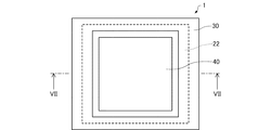
次に、第1実施形態に係る発光装置100の製造方法について、図面を参照しながら説明する。図3は、第1実施形態に係る発光装置100の製造方法の一例を示すフローチャートである。図4〜図8は、第1実施形態に係る発光装置100の製造工程を模式的に示す図である。なお、図5は、図6のV−V線断面図であり、図7は、図8のVII−VII線断面図である。
第1基体10の主面11に、発光部2を含む積層体20を形成する。
図7および図8に示すように、第1基体10上(領域12)および第1半導体層22上(領域23)に第1電極30を形成し、積層体20上(第2半導体層26上)に第2電極40を形成する。
図1および図2に示すように、第1基体10に形成された積層体20(第2電極40)および第1電極30を第2基体50に接続して、発光素子1を第2基体50に実装する。
成した後、第1電極30が接合部材70に接し、第2電極40が接合部材72に接するように発光素子1を第2基体50上に配置した状態で、加熱する。これにより、第1電極30と第1配線60とが接続(接合)され、第2電極40と第2配線62とが接続(接合)される。この接合を不活性ガス雰囲気中で行うことにより、積層体20を収容する空間を不活性ガス雰囲気にすることができる。
1.3.1. 発光装置
次に、第1実施形態の変形例に係る発光装置について、図面を参照しながら説明する。図9は、第1実施形態の変形例に係る発光装置110を模式的に示す断面図である。なお、第1実施形態の変形例に係る発光装置110の平面形状は、図2に示す発光装置100の平面形状と同様であり、図示を省略する。
間に設けられている。バッファー層21は、例えば、アンドープのGaN層である。
折率は、例えば、半導体層22,26および発光層24の屈折率よりも低い。
次に、第1実施形態の変形例に係る発光装置110の製造方法について説明する。図10〜図12は、第1実施形態の変形例に係る発光装置110の製造工程を模式的に示す断面図である。
まず、第1基体10の主面11に、発光部2を含む積層体20を形成する。
形成される。
次に、図12に示すように、第1基体10上(領域12)および第1半導体層22上(領域23)に第1電極30を形成し、積層体20上(第2半導体層26上)に第2電極40を形成する。本工程は、上述した発光装置100の製造方法における第1電極30および第2電極40を形成する工程(S12)と同様に行われる。以上の工程により、発光素子1を形成することができる。
次に、図9に示すように、発光素子1を第2基体50に実装する。本工程は、上述した発光装置100の製造方法における実装工程(S14)と同様に行われる。
2.1. 発光装置
次に、第2実施形態に係る発光装置について、図面を参照しながら説明する。図13は、第2実施形態に係る発光装置200を模式的に示す断面図である。なお、第2実施形態に係る発光装置200の平面形状は、図2に示す発光装置100の平面形状と同様であり、図示を省略する。
。
次に、本実施形態に係る発光装置200の製造方法について説明する。図14〜図16は、第2実施形態に係る発光装置200の製造工程を模式的に示す断面図である。
まず、第1基体10の主面11に、発光部2を含む積層体20を形成する。本工程は、上述した発光装置100の製造方法における積層体20を形成する工程(S10)と同様に行われる。
次に、図14に示すように、第1基体10上(領域12)および第1半導体層22上(領域23)に第1電極30を形成し、積層体20上(第2半導体層26上)に第2電極40を形成する。
次に、第1基体10に形成された積層体20(第2電極40)および第1電極30を第2基体50に接続して、発光素子1を第2基体50に実装する。
ースト72bとが接合部材72を形成する。この接合を不活性ガス雰囲気中で行うことにより、積層体20を収容する空間を不活性ガス雰囲気にすることができる。
2.3.1. 発光装置
次に、第2実施形態の変形例に係る発光装置について、図面を参照しながら説明する。図17は、第2実施形態の変形例に係る発光装置210を模式的に示す断面図である。なお、第2実施形態の変形例に係る発光装置210の平面形状は、図2に示す発光装置100の平面形状と同様であり、図示を省略する。
次に、本変形例に係る発光装置210の製造方法について説明する。発光装置210の製造方法は、図3に示す発光装置100の製造方法と同様に、積層体20を形成する工程(S10)と、第1電極30および第2電極40を形成する工程(S12)と、実装工程(S14)と、を含む。
様の作用効果を奏することができる。
3.1. 発光装置
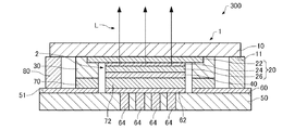
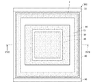
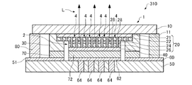
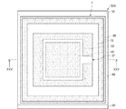
次に、第3実施形態に係る発光装置について、図面を参照しながら説明する。図18は、第3実施形態に係る発光装置300を模式的に示す断面図である。図19は、第3実施形態に係る発光装置300を模式的に示す平面図である。なお、図18は、図19のXVIII−XVIII線断面図である。
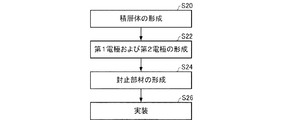
次に、第3実施形態に係る発光装置300の製造方法について、図面を参照しながら説明する。図20は、第3実施形態に係る発光装置300の製造方法の一例を示すフローチャートである。図21は、第3実施形態に係る発光装置300の製造工程を模式的に示す断面図である。
まず、第1基体10の主面11に、発光部2を含む積層体20を形成する。本工程は、上述した発光装置100の製造方法における積層体20を形成する工程(S10)と同様に行われる。
次に、第1基体10上(領域12)および第1半導体層22上(領域23)に第1電極30を形成し、積層体20上(第2半導体層26上)に第2電極40を形成する。本工程は、上述した発光装置100の製造方法における第1電極30および第2電極40を形成する工程(S12)と同様に行われる。以上の工程により、発光素子1を形成することができる(図7参照)。
次に、図21に示すように、第2基体50の主面51に封止部材80を形成する。具体的には、第2基体50の主面51にガラスフリットを塗布し、当該ガラスフリットを焼成することで、封止部材80を形成する。このように、事前にガラスフリットを焼成することにより、ガラスフリット内の溶媒を飛ばして、封止部材80で封止される空間への溶媒の残留を防ぐことができる。なお、第2基体50には、あらかじめ第1配線60、第2配線62、および貫通電極64を形成しておく。
次に、図18および図19に示すように、発光素子1を第2基体50に実装する。
れた積層体20が第2基体50に押しつけられるため、積層体20に圧力が加わる。このとき、第1基体10には、積層体20に加えて第1電極30が形成され、第2基体50には封止部材80が形成されている。そのため、実装時に加えられる力が、積層体20と、第1電極30と、封止部材80と、に分散され、積層体20(発光部2)に加わる圧力を低減できる。
次に、第3実施形態の変形例に係る発光装置について、図面を参照しながら説明する。図22は、第3実施形態の変形例に係る発光装置310を模式的に示す断面図である。なお、第3実施形態の変形例に係る発光装置310の平面形状は、図19に示す発光装置300の平面形状と同様であり、図示を省略する。
さらに、発光装置310では、上述した発光装置110と同様に、優れた発光特性を有することができる。
4.1. 発光装置
次に、第4実施形態に係る発光装置について、図面を参照しながら説明する。図23は、第4実施形態に係る発光装置400を模式的に示す断面図である。なお、第4実施形態に係る発光装置400の平面形状は、図19に示す発光装置300の平面形状と同様であり、図示を省略する。
次に、第4実施形態に係る発光装置400の製造方法について説明する。第4実施形態に係る発光装置400の製造方法は、上述した第2実施形態に係る発光装置200の製造方法および第3実施形態に係る発光装置300の製造方法を組み合わせることで製造することができる。
次に、第4実施形態の変形例に係る発光装置について、図面を参照しながら説明する。図24は、第4実施形態の変形例に係る発光装置410を模式的に示す断面図である。なお、第4実施形態の変形例に係る発光装置410の平面形状は、図19に示す発光装置300の平面形状と同様であり、図示を省略する。
5.1. 発光装置
次に、第5実施形態に係る発光装置について図面を参照しながら説明する。図25は、第5実施形態に係る発光装置500を模式的に示す断面図である。図26は、第5実施形態に係る発光装置500を模式的に示す平面図である。なお、図25は、図26のXXV−XXV線断面図である。
次に、第5実施形態に係る発光装置500の製造方法について説明する。第5実施形態に係る発光装置500の製造方法は、第1電極30にスリット部32を設ける点、スリット部32を通してガスの排気を行う点が、上述した第4実施形態に係る発光装置400の製造方法と異なる。以下、この相違点について説明する。
電性ペースト)で接合する。このとき、導電性ペーストの焼成により接合部材70,72からガスが発生する。次に、スリット部32を通して、第1電極30の内側の空間からガスを排気し、不活性ガスに置換する。次に、封止部材80にレーザーを照射して、封止部材80の一端を第1基体10に融着させ、封止部材80の他端を第2基体50に融着させる。これにより、積層体20および第1電極30を気密に封止することができる。
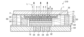
次に、第5実施形態の変形例に係る発光装置について、図面を参照しながら説明する。図27は、第5実施形態の変形例に係る発光装置510を模式的に示す断面図である。なお、第5実施形態の変形例に係る発光装置510の平面形状は、図26に示す発光装置500の平面形状と同様であり、図示を省略する。
次に、第6実施形態に係るプロジェクターについて、図面を参照しながら説明する。図28は、第6実施形態に係るプロジェクター900を模式的に示す図である。
の光をスクリーン上で走査させることにより、表示面に所望の大きさの画像を表示させる画像形成装置である走査手段を有するような走査型の画像表示装置(プロジェクター)の光源装置にも適用することが可能である。
なお、本発明は上述した実施形態に限定されず、本発明の要旨の範囲内で種々の変形実施が可能である。
イトバルブ、904G…液晶ライトバルブ、904B…液晶ライトバルブ、906…クロスダイクロイックプリズム、908…投射レンズ、910…スクリーン
Claims (13)
- 積層体が設けられている第1基体を含む発光素子と、
前記発光素子が設けられている第2基体と、
を含み、
前記積層体は、複数の柱状部を有し、前記第1基体と反対側において前記第2基体に接続され、
前記複数の柱状部は、複数の第1柱状部と、複数の第2柱状部と、を含み、
複数の前記第1柱状部の各々は、
第1半導体層と、
前記第1半導体層と導電型の異なる第2半導体層と、
前記第1半導体層と前記第2半導体層との間に設けられ、電流が注入されることで光を発することが可能な発光層と、
を有し、
前記第1基体と前記第2基体との間に第1部材が設けられ、
前記第1部材は、一端が前記第1基体に接続され、他端が前記第2基体に接続され、
前記積層体は、発光部を含み、
前記発光部は、複数の前記第1柱状部で構成され、
前記第1基体と前記第1部材との間に前記第2柱状部が設けられ、
前記第2柱状部の高さは、前記第1柱状部の高さよりも小さく、
前記第1部材は導電性を有し、前記第1半導体層に電気的に接続されている、発光装置。 - 積層体が設けられている第1基体を含む発光素子と、
前記発光素子が設けられている第2基体と、
を含み、
前記積層体は、複数の柱状部を有し、前記第1基体と反対側において前記第2基体に接続され、
前記複数の柱状部は、複数の第1柱状部と、複数の第2柱状部と、を含み、
複数の前記第1柱状部の各々は、
第1半導体層と、
前記第1半導体層と導電型の異なる第2半導体層と、
前記第1半導体層と前記第2半導体層との間に設けられ、電流が注入されることで光を発することが可能な発光層と、
を有し、
前記第1基体と前記第2基体との間に第1部材が設けられ、
前記第1部材は、一端が前記第1基体に接続され、他端が前記第2基体に接続され、
前記積層体は、発光部を含み、
前記発光部は、複数の前記第1柱状部で構成され、
前記第1基体と前記第1部材との間に前記第2柱状部が設けられ、
前記第2柱状部の高さは、前記第1柱状部の高さよりも小さく、
前記第1基体と前記第2基体との間に設けられている第2部材を含み、
前記第2部材は、一端が前記第1基体に接続され、他端が前記第2基体に接続されている、発光装置。 - 請求項1または2において、
前記第1部材は、前記積層体の周囲を囲って設けられている、発光装置。 - 請求項3において、
前記積層体は、前記第1部材、前記第1基体、および前記第2基体によって気密に封止されている、発光装置。 - 請求項2において、
前記第1部材は導電性を有し、前記第1半導体層に電気的に接続されている、発光装置。 - 請求項2において、
前記第2部材は、前記第1部材および前記積層体の周囲を囲っている、発光装置。 - 請求項2または6において、
前記第2部材は絶縁性であり、前記第1半導体層、前記第2半導体層、および前記発光層に電気的に接続されていない、発光装置。 - 請求項1ないし7のいずれか1項において、
前記第2基体には、前記第2基体を貫通する貫通電極が設けられている、発光装置。 - 請求項8において、
前記第2半導体層は、前記貫通電極に電気的に接続されている、発光装置。 - 請求項1ないし9のいずれか1項において、
前記第1部材は、接合部材を介して前記第2基体に接続されている、発光装置。 - 請求項1ないし10のいずれか1項に記載の発光装置を含む、プロジェクター。
- 第1基体に、発光部を含む積層体を形成する工程と、
前記第1基体に、第1部材を形成する工程と、
前記第1基体に形成された前記積層体および前記第1部材を、第2基体に接続する工程と、
を含み、
前記積層体は、複数の柱状部を有し、前記第1基体と反対側において前記第2基体に接続され、
前記複数の柱状部は、複数の第1柱状部と、複数の第2柱状部と、を含み、
複数の前記第1柱状部の各々は、
第1半導体層と、
前記第1半導体層と導電型の異なる第2半導体層と、
前記第1半導体層と前記第2半導体層との間に設けられ、電流が注入されることで光を発することが可能な発光層と、
を有し、
前記第1基体と前記第2基体との間に前記第1部材が設けられ、
前記第1部材は、一端が前記第1基体に接続され、他端が前記第2基体に接続され、
前記発光部は、複数の前記第1柱状部で構成され、
前記第1基体と前記第1部材との間に前記第2柱状部が設けられ、
前記第2柱状部の高さは、前記第1柱状部の高さよりも小さく、
前記第1部材は導電性を有し、前記第1半導体層に電気的に接続されている、発光装置の製造方法。 - 第1基体に、発光部を含む積層体を形成する工程と、
前記第1基体に、第1部材を形成する工程と、
前記第1基体に形成された前記積層体および前記第1部材を、第2基体に接続する工程と、
前記第1基体と前記第2基体との間に設けられ、一端が前記第1基体に接続され、他端が前記第2基体に接続されている第2部材を設ける工程と、
を含み、
前記積層体は、複数の柱状部を有し、前記第1基体と反対側において前記第2基体に接続され、
前記複数の柱状部は、複数の第1柱状部と、複数の第2柱状部と、を含み、
複数の前記第1柱状部の各々は、
第1半導体層と、
前記第1半導体層と導電型の異なる第2半導体層と、
前記第1半導体層と前記第2半導体層との間に設けられ、電流が注入されることで光を発することが可能な発光層と、
を有し、
前記第1基体と前記第2基体との間に前記第1部材が設けられ、
前記第1部材は、一端が前記第1基体に接続され、他端が前記第2基体に接続され、
前記発光部は、複数の前記第1柱状部で構成され、
前記第1基体と前記第1部材との間に前記第2柱状部が設けられ、
前記第2柱状部の高さは、前記第1柱状部の高さよりも小さい、発光装置の製造方法。
Priority Applications (4)
| Application Number | Priority Date | Filing Date | Title |
|---|---|---|---|
| JP2017108346A JP6972665B2 (ja) | 2017-05-31 | 2017-05-31 | 発光装置、プロジェクター、および発光装置の製造方法 |
| CN201880034936.2A CN110678991B (zh) | 2017-05-31 | 2018-05-23 | 发光装置、投影仪以及发光装置的制造方法 |
| US16/618,088 US11239390B2 (en) | 2017-05-31 | 2018-05-23 | Light emitting apparatus, projector, method for manufacturing light emitting apparatus |
| PCT/JP2018/019841 WO2018221351A1 (ja) | 2017-05-31 | 2018-05-23 | 発光装置、プロジェクター、および発光装置の製造方法 |
Applications Claiming Priority (1)
| Application Number | Priority Date | Filing Date | Title |
|---|---|---|---|
| JP2017108346A JP6972665B2 (ja) | 2017-05-31 | 2017-05-31 | 発光装置、プロジェクター、および発光装置の製造方法 |
Publications (3)
| Publication Number | Publication Date |
|---|---|
| JP2018206860A JP2018206860A (ja) | 2018-12-27 |
| JP2018206860A5 JP2018206860A5 (ja) | 2020-07-02 |
| JP6972665B2 true JP6972665B2 (ja) | 2021-11-24 |
Family
ID=64455337
Family Applications (1)
| Application Number | Title | Priority Date | Filing Date |
|---|---|---|---|
| JP2017108346A Active JP6972665B2 (ja) | 2017-05-31 | 2017-05-31 | 発光装置、プロジェクター、および発光装置の製造方法 |
Country Status (4)
| Country | Link |
|---|---|
| US (1) | US11239390B2 (ja) |
| JP (1) | JP6972665B2 (ja) |
| CN (1) | CN110678991B (ja) |
| WO (1) | WO2018221351A1 (ja) |
Cited By (1)
| Publication number | Priority date | Publication date | Assignee | Title |
|---|---|---|---|---|
| JP2018206861A (ja) * | 2017-05-31 | 2018-12-27 | セイコーエプソン株式会社 | 発光装置、プロジェクター、および発光装置の製造方法 |
Families Citing this family (3)
| Publication number | Priority date | Publication date | Assignee | Title |
|---|---|---|---|---|
| JP6954562B2 (ja) * | 2017-09-15 | 2021-10-27 | セイコーエプソン株式会社 | 発光装置およびその製造方法、ならびにプロジェクター |
| JP2021150373A (ja) * | 2020-03-17 | 2021-09-27 | セイコーエプソン株式会社 | 発光装置、プロジェクター、およびディスプレイ |
| JP2024108649A (ja) * | 2023-01-31 | 2024-08-13 | ウシオ電機株式会社 | 光源装置 |
Family Cites Families (22)
| Publication number | Priority date | Publication date | Assignee | Title |
|---|---|---|---|---|
| JP2000261088A (ja) | 1999-03-05 | 2000-09-22 | Hitachi Ltd | 発光素子 |
| US7022550B2 (en) * | 2004-04-07 | 2006-04-04 | Gelcore Llc | Methods for forming aluminum-containing p-contacts for group III-nitride light emitting diodes |
| KR100624419B1 (ko) * | 2004-04-07 | 2006-09-19 | 삼성전자주식회사 | 나노와이어 발광소자 및 그 제조방법 |
| JP2008047850A (ja) | 2006-07-19 | 2008-02-28 | Mitsubishi Cable Ind Ltd | 窒化物半導体発光ダイオード素子 |
| JP2007235122A (ja) * | 2006-02-02 | 2007-09-13 | Matsushita Electric Ind Co Ltd | 半導体発光装置及びその製造方法 |
| US7786491B2 (en) | 2006-02-02 | 2010-08-31 | Panasonic Corporation | Semiconductor light-emitting device comprising a plurality of semiconductor layers |
| JP5029079B2 (ja) | 2007-03-15 | 2012-09-19 | 富士ゼロックス株式会社 | 半導体素子および光学装置 |
| JP4984170B2 (ja) * | 2008-04-01 | 2012-07-25 | 日本電信電話株式会社 | 光半導体素子の実装構造 |
| US20100038670A1 (en) * | 2008-08-18 | 2010-02-18 | Luminus Devices, Inc. | Illumination assembly including chip-scale packaged light-emitting device |
| KR101567121B1 (ko) * | 2008-09-01 | 2015-11-06 | 가꼬호징 조찌가꾸잉 | 반도체 광소자 어레이 및 그의 제조방법 |
| US20100117070A1 (en) * | 2008-09-18 | 2010-05-13 | Lumenz Llc | Textured semiconductor light-emitting devices |
| JP2010153561A (ja) * | 2008-12-25 | 2010-07-08 | Nichia Corp | 発光装置 |
| CN101859824A (zh) * | 2009-04-07 | 2010-10-13 | 山东璨圆光电科技有限公司 | 双回路电极设计的发光二极管芯片 |
| JP5679117B2 (ja) * | 2011-03-09 | 2015-03-04 | セイコーエプソン株式会社 | 発光装置、照射装置、およびプロジェクター |
| JP2013042079A (ja) | 2011-08-19 | 2013-02-28 | Sharp Corp | 半導体発光装置 |
| JPWO2013161208A1 (ja) * | 2012-04-27 | 2015-12-21 | パナソニックIpマネジメント株式会社 | 発光素子 |
| JP2015056652A (ja) * | 2013-09-13 | 2015-03-23 | 株式会社東芝 | 窒化物半導体発光装置 |
| KR20150035111A (ko) * | 2013-09-27 | 2015-04-06 | 서울바이오시스 주식회사 | 주변 발광부를 구비하는 발광다이오드 칩 |
| US10304998B2 (en) * | 2013-09-27 | 2019-05-28 | Seoul Viosys Co., Ltd. | Light emitting diode chip and light emitting device having the same |
| US10910350B2 (en) * | 2014-05-24 | 2021-02-02 | Hiphoton Co., Ltd. | Structure of a semiconductor array |
| CN204144306U (zh) * | 2014-09-16 | 2015-02-04 | 惠州比亚迪实业有限公司 | Led芯片 |
| EA201890167A1 (ru) * | 2015-07-13 | 2018-07-31 | Крайонано Ас | Светодиоды и фотодетекторы, сформированные из нанопроводников/нанопирамид |
-
2017
- 2017-05-31 JP JP2017108346A patent/JP6972665B2/ja active Active
-
2018
- 2018-05-23 WO PCT/JP2018/019841 patent/WO2018221351A1/ja active Application Filing
- 2018-05-23 CN CN201880034936.2A patent/CN110678991B/zh active Active
- 2018-05-23 US US16/618,088 patent/US11239390B2/en active Active
Cited By (2)
| Publication number | Priority date | Publication date | Assignee | Title |
|---|---|---|---|---|
| JP2018206861A (ja) * | 2017-05-31 | 2018-12-27 | セイコーエプソン株式会社 | 発光装置、プロジェクター、および発光装置の製造方法 |
| JP7147132B2 (ja) | 2017-05-31 | 2022-10-05 | セイコーエプソン株式会社 | 発光装置、プロジェクター、および発光装置の製造方法 |
Also Published As
| Publication number | Publication date |
|---|---|
| CN110678991B (zh) | 2022-12-23 |
| CN110678991A (zh) | 2020-01-10 |
| US20200152833A1 (en) | 2020-05-14 |
| JP2018206860A (ja) | 2018-12-27 |
| WO2018221351A1 (ja) | 2018-12-06 |
| US11239390B2 (en) | 2022-02-01 |
Similar Documents
| Publication | Publication Date | Title |
|---|---|---|
| JP6972665B2 (ja) | 発光装置、プロジェクター、および発光装置の製造方法 | |
| JP6935657B2 (ja) | 発光装置およびプロジェクター | |
| JP7056628B2 (ja) | 発光装置およびプロジェクター | |
| JP7008295B2 (ja) | 発光装置およびプロジェクター | |
| CN110679046B (zh) | 发光装置、投影仪以及发光装置的制造方法 | |
| JP2021007136A (ja) | 発光装置およびプロジェクター | |
| JP7017761B2 (ja) | 発光装置、プロジェクター、およびディスプレイ | |
| JP2017138566A (ja) | 光源装置、光源装置の製造方法およびプロジェクター | |
| US8955987B2 (en) | Light emitting device, super-luminescent diode, and projector | |
| JP2013239614A (ja) | 発光装置の製造方法 | |
| JP2020161621A (ja) | 発光装置およびプロジェクター | |
| JP2017139444A (ja) | 光源装置、光源装置の製造方法およびプロジェクター | |
| JP2022011468A (ja) | 発光装置およびプロジェクター | |
| WO2019026692A1 (ja) | 発光装置およびプロジェクター | |
| JP7188690B2 (ja) | プロジェクター | |
| JP2011061075A (ja) | プロジェクター | |
| JP2021100048A (ja) | 発光装置、および、プロジェクター | |
| JP2017041479A (ja) | 接合体、電子装置、プロジェクターおよび接合体の製造方法 | |
| JP2021057443A (ja) | 発光装置、および、プロジェクター | |
| US11803115B2 (en) | Light-emitting device and projector | |
| JP7230901B2 (ja) | 発光装置およびプロジェクター | |
| US20230139048A1 (en) | Light-emitting device and projector | |
| JP2022079897A (ja) | 発光装置、プロジェクター、及び、発光装置の製造方法。 | |
| JP2022011467A (ja) | 発光装置、プロジェクター、および発光装置の製造方法 |
Legal Events
| Date | Code | Title | Description |
|---|---|---|---|
| A521 | Request for written amendment filed |
Free format text: JAPANESE INTERMEDIATE CODE: A523 Effective date: 20200513 |
|
| A621 | Written request for application examination |
Free format text: JAPANESE INTERMEDIATE CODE: A621 Effective date: 20200513 |
|
| A131 | Notification of reasons for refusal |
Free format text: JAPANESE INTERMEDIATE CODE: A131 Effective date: 20210316 |
|
| A521 | Request for written amendment filed |
Free format text: JAPANESE INTERMEDIATE CODE: A523 Effective date: 20210511 |
|
| A131 | Notification of reasons for refusal |
Free format text: JAPANESE INTERMEDIATE CODE: A131 Effective date: 20210629 |
|
| A521 | Request for written amendment filed |
Free format text: JAPANESE INTERMEDIATE CODE: A523 Effective date: 20210824 |
|
| TRDD | Decision of grant or rejection written | ||
| A01 | Written decision to grant a patent or to grant a registration (utility model) |
Free format text: JAPANESE INTERMEDIATE CODE: A01 Effective date: 20211005 |
|
| A61 | First payment of annual fees (during grant procedure) |
Free format text: JAPANESE INTERMEDIATE CODE: A61 Effective date: 20211018 |
|
| R150 | Certificate of patent or registration of utility model |
Ref document number: 6972665 Country of ref document: JP Free format text: JAPANESE INTERMEDIATE CODE: R150 |


