JP6879690B2 - Resin composition for heat dissipation, its cured product, and how to use them - Google Patents
Resin composition for heat dissipation, its cured product, and how to use them Download PDFInfo
- Publication number
- JP6879690B2 JP6879690B2 JP2016154987A JP2016154987A JP6879690B2 JP 6879690 B2 JP6879690 B2 JP 6879690B2 JP 2016154987 A JP2016154987 A JP 2016154987A JP 2016154987 A JP2016154987 A JP 2016154987A JP 6879690 B2 JP6879690 B2 JP 6879690B2
- Authority
- JP
- Japan
- Prior art keywords
- heat
- resin composition
- dissipating
- semiconductor element
- dissipating resin
- Prior art date
- Legal status (The legal status is an assumption and is not a legal conclusion. Google has not performed a legal analysis and makes no representation as to the accuracy of the status listed.)
- Active
Links
Images


Classifications
-
- C—CHEMISTRY; METALLURGY
- C08—ORGANIC MACROMOLECULAR COMPOUNDS; THEIR PREPARATION OR CHEMICAL WORKING-UP; COMPOSITIONS BASED THEREON
- C08L—COMPOSITIONS OF MACROMOLECULAR COMPOUNDS
- C08L63/00—Compositions of epoxy resins; Compositions of derivatives of epoxy resins
-
- C—CHEMISTRY; METALLURGY
- C08—ORGANIC MACROMOLECULAR COMPOUNDS; THEIR PREPARATION OR CHEMICAL WORKING-UP; COMPOSITIONS BASED THEREON
- C08L—COMPOSITIONS OF MACROMOLECULAR COMPOUNDS
- C08L63/00—Compositions of epoxy resins; Compositions of derivatives of epoxy resins
- C08L63/04—Epoxynovolacs
-
- C—CHEMISTRY; METALLURGY
- C08—ORGANIC MACROMOLECULAR COMPOUNDS; THEIR PREPARATION OR CHEMICAL WORKING-UP; COMPOSITIONS BASED THEREON
- C08G—MACROMOLECULAR COMPOUNDS OBTAINED OTHERWISE THAN BY REACTIONS ONLY INVOLVING UNSATURATED CARBON-TO-CARBON BONDS
- C08G59/00—Polycondensates containing more than one epoxy group per molecule; Macromolecules obtained by polymerising compounds containing more than one epoxy group per molecule using curing agents or catalysts which react with the epoxy groups
- C08G59/18—Macromolecules obtained by polymerising compounds containing more than one epoxy group per molecule using curing agents or catalysts which react with the epoxy groups ; e.g. general methods of curing
-
- C—CHEMISTRY; METALLURGY
- C08—ORGANIC MACROMOLECULAR COMPOUNDS; THEIR PREPARATION OR CHEMICAL WORKING-UP; COMPOSITIONS BASED THEREON
- C08K—Use of inorganic or non-macromolecular organic substances as compounding ingredients
- C08K5/00—Use of organic ingredients
- C08K5/0008—Organic ingredients according to more than one of the "one dot" groups of C08K5/01 - C08K5/59
- C08K5/0025—Crosslinking or vulcanising agents; including accelerators
-
- C—CHEMISTRY; METALLURGY
- C08—ORGANIC MACROMOLECULAR COMPOUNDS; THEIR PREPARATION OR CHEMICAL WORKING-UP; COMPOSITIONS BASED THEREON
- C08L—COMPOSITIONS OF MACROMOLECULAR COMPOUNDS
- C08L33/00—Compositions of homopolymers or copolymers of compounds having one or more unsaturated aliphatic radicals, each having only one carbon-to-carbon double bond, and only one being terminated by only one carboxyl radical, or of salts, anhydrides, esters, amides, imides or nitriles thereof; Compositions of derivatives of such polymers
- C08L33/04—Homopolymers or copolymers of esters
- C08L33/06—Homopolymers or copolymers of esters of esters containing only carbon, hydrogen and oxygen, which oxygen atoms are present only as part of the carboxyl radical
- C08L33/062—Copolymers with monomers not covered by C08L33/06
- C08L33/064—Copolymers with monomers not covered by C08L33/06 containing anhydride, COOH or COOM groups, with M being metal or onium-cation
-
- C—CHEMISTRY; METALLURGY
- C08—ORGANIC MACROMOLECULAR COMPOUNDS; THEIR PREPARATION OR CHEMICAL WORKING-UP; COMPOSITIONS BASED THEREON
- C08L—COMPOSITIONS OF MACROMOLECULAR COMPOUNDS
- C08L33/00—Compositions of homopolymers or copolymers of compounds having one or more unsaturated aliphatic radicals, each having only one carbon-to-carbon double bond, and only one being terminated by only one carboxyl radical, or of salts, anhydrides, esters, amides, imides or nitriles thereof; Compositions of derivatives of such polymers
- C08L33/04—Homopolymers or copolymers of esters
- C08L33/06—Homopolymers or copolymers of esters of esters containing only carbon, hydrogen and oxygen, which oxygen atoms are present only as part of the carboxyl radical
- C08L33/08—Homopolymers or copolymers of acrylic acid esters
-
- H—ELECTRICITY
- H01—ELECTRIC ELEMENTS
- H01L—SEMICONDUCTOR DEVICES NOT COVERED BY CLASS H10
- H01L21/00—Processes or apparatus adapted for the manufacture or treatment of semiconductor or solid state devices or of parts thereof
- H01L21/02—Manufacture or treatment of semiconductor devices or of parts thereof
- H01L21/04—Manufacture or treatment of semiconductor devices or of parts thereof the devices having at least one potential-jump barrier or surface barrier, e.g. PN junction, depletion layer or carrier concentration layer
- H01L21/50—Assembly of semiconductor devices using processes or apparatus not provided for in a single one of the subgroups H01L21/06 - H01L21/326, e.g. sealing of a cap to a base of a container
- H01L21/56—Encapsulations, e.g. encapsulation layers, coatings
- H01L21/563—Encapsulation of active face of flip-chip device, e.g. underfilling or underencapsulation of flip-chip, encapsulation preform on chip or mounting substrate
-
- H—ELECTRICITY
- H01—ELECTRIC ELEMENTS
- H01L—SEMICONDUCTOR DEVICES NOT COVERED BY CLASS H10
- H01L23/00—Details of semiconductor or other solid state devices
- H01L23/28—Encapsulations, e.g. encapsulating layers, coatings, e.g. for protection
- H01L23/29—Encapsulations, e.g. encapsulating layers, coatings, e.g. for protection characterised by the material, e.g. carbon
- H01L23/293—Organic, e.g. plastic
- H01L23/295—Organic, e.g. plastic containing a filler
-
- H—ELECTRICITY
- H01—ELECTRIC ELEMENTS
- H01L—SEMICONDUCTOR DEVICES NOT COVERED BY CLASS H10
- H01L23/00—Details of semiconductor or other solid state devices
- H01L23/28—Encapsulations, e.g. encapsulating layers, coatings, e.g. for protection
- H01L23/31—Encapsulations, e.g. encapsulating layers, coatings, e.g. for protection characterised by the arrangement or shape
- H01L23/3107—Encapsulations, e.g. encapsulating layers, coatings, e.g. for protection characterised by the arrangement or shape the device being completely enclosed
- H01L23/3121—Encapsulations, e.g. encapsulating layers, coatings, e.g. for protection characterised by the arrangement or shape the device being completely enclosed a substrate forming part of the encapsulation
-
- H—ELECTRICITY
- H01—ELECTRIC ELEMENTS
- H01L—SEMICONDUCTOR DEVICES NOT COVERED BY CLASS H10
- H01L23/00—Details of semiconductor or other solid state devices
- H01L23/34—Arrangements for cooling, heating, ventilating or temperature compensation ; Temperature sensing arrangements
- H01L23/36—Selection of materials, or shaping, to facilitate cooling or heating, e.g. heatsinks
- H01L23/373—Cooling facilitated by selection of materials for the device or materials for thermal expansion adaptation, e.g. carbon
- H01L23/3737—Organic materials with or without a thermoconductive filler
-
- H—ELECTRICITY
- H01—ELECTRIC ELEMENTS
- H01L—SEMICONDUCTOR DEVICES NOT COVERED BY CLASS H10
- H01L24/00—Arrangements for connecting or disconnecting semiconductor or solid-state bodies; Methods or apparatus related thereto
- H01L24/01—Means for bonding being attached to, or being formed on, the surface to be connected, e.g. chip-to-package, die-attach, "first-level" interconnects; Manufacturing methods related thereto
- H01L24/26—Layer connectors, e.g. plate connectors, solder or adhesive layers; Manufacturing methods related thereto
- H01L24/28—Structure, shape, material or disposition of the layer connectors prior to the connecting process
- H01L24/29—Structure, shape, material or disposition of the layer connectors prior to the connecting process of an individual layer connector
-
- H—ELECTRICITY
- H01—ELECTRIC ELEMENTS
- H01L—SEMICONDUCTOR DEVICES NOT COVERED BY CLASS H10
- H01L24/00—Arrangements for connecting or disconnecting semiconductor or solid-state bodies; Methods or apparatus related thereto
- H01L24/80—Methods for connecting semiconductor or other solid state bodies using means for bonding being attached to, or being formed on, the surface to be connected
- H01L24/83—Methods for connecting semiconductor or other solid state bodies using means for bonding being attached to, or being formed on, the surface to be connected using a layer connector
-
- H—ELECTRICITY
- H01—ELECTRIC ELEMENTS
- H01L—SEMICONDUCTOR DEVICES NOT COVERED BY CLASS H10
- H01L24/00—Arrangements for connecting or disconnecting semiconductor or solid-state bodies; Methods or apparatus related thereto
- H01L24/98—Methods for disconnecting semiconductor or solid-state bodies
-
- C—CHEMISTRY; METALLURGY
- C08—ORGANIC MACROMOLECULAR COMPOUNDS; THEIR PREPARATION OR CHEMICAL WORKING-UP; COMPOSITIONS BASED THEREON
- C08L—COMPOSITIONS OF MACROMOLECULAR COMPOUNDS
- C08L2203/00—Applications
- C08L2203/20—Applications use in electrical or conductive gadgets
- C08L2203/206—Applications use in electrical or conductive gadgets use in coating or encapsulating of electronic parts
-
- C—CHEMISTRY; METALLURGY
- C08—ORGANIC MACROMOLECULAR COMPOUNDS; THEIR PREPARATION OR CHEMICAL WORKING-UP; COMPOSITIONS BASED THEREON
- C08L—COMPOSITIONS OF MACROMOLECULAR COMPOUNDS
- C08L2205/00—Polymer mixtures characterised by other features
- C08L2205/03—Polymer mixtures characterised by other features containing three or more polymers in a blend
-
- C—CHEMISTRY; METALLURGY
- C08—ORGANIC MACROMOLECULAR COMPOUNDS; THEIR PREPARATION OR CHEMICAL WORKING-UP; COMPOSITIONS BASED THEREON
- C08L—COMPOSITIONS OF MACROMOLECULAR COMPOUNDS
- C08L2205/00—Polymer mixtures characterised by other features
- C08L2205/05—Polymer mixtures characterised by other features containing polymer components which can react with one another
-
- C—CHEMISTRY; METALLURGY
- C08—ORGANIC MACROMOLECULAR COMPOUNDS; THEIR PREPARATION OR CHEMICAL WORKING-UP; COMPOSITIONS BASED THEREON
- C08L—COMPOSITIONS OF MACROMOLECULAR COMPOUNDS
- C08L2312/00—Crosslinking
- C08L2312/06—Crosslinking by radiation
-
- H—ELECTRICITY
- H01—ELECTRIC ELEMENTS
- H01L—SEMICONDUCTOR DEVICES NOT COVERED BY CLASS H10
- H01L2224/00—Indexing scheme for arrangements for connecting or disconnecting semiconductor or solid-state bodies and methods related thereto as covered by H01L24/00
- H01L2224/01—Means for bonding being attached to, or being formed on, the surface to be connected, e.g. chip-to-package, die-attach, "first-level" interconnects; Manufacturing methods related thereto
- H01L2224/10—Bump connectors; Manufacturing methods related thereto
- H01L2224/12—Structure, shape, material or disposition of the bump connectors prior to the connecting process
- H01L2224/13—Structure, shape, material or disposition of the bump connectors prior to the connecting process of an individual bump connector
- H01L2224/13001—Core members of the bump connector
- H01L2224/13099—Material
- H01L2224/131—Material with a principal constituent of the material being a metal or a metalloid, e.g. boron [B], silicon [Si], germanium [Ge], arsenic [As], antimony [Sb], tellurium [Te] and polonium [Po], and alloys thereof
- H01L2224/13101—Material with a principal constituent of the material being a metal or a metalloid, e.g. boron [B], silicon [Si], germanium [Ge], arsenic [As], antimony [Sb], tellurium [Te] and polonium [Po], and alloys thereof the principal constituent melting at a temperature of less than 400°C
-
- H—ELECTRICITY
- H01—ELECTRIC ELEMENTS
- H01L—SEMICONDUCTOR DEVICES NOT COVERED BY CLASS H10
- H01L2224/00—Indexing scheme for arrangements for connecting or disconnecting semiconductor or solid-state bodies and methods related thereto as covered by H01L24/00
- H01L2224/01—Means for bonding being attached to, or being formed on, the surface to be connected, e.g. chip-to-package, die-attach, "first-level" interconnects; Manufacturing methods related thereto
- H01L2224/10—Bump connectors; Manufacturing methods related thereto
- H01L2224/12—Structure, shape, material or disposition of the bump connectors prior to the connecting process
- H01L2224/13—Structure, shape, material or disposition of the bump connectors prior to the connecting process of an individual bump connector
- H01L2224/13001—Core members of the bump connector
- H01L2224/13099—Material
- H01L2224/13198—Material with a principal constituent of the material being a combination of two or more materials in the form of a matrix with a filler, i.e. being a hybrid material, e.g. segmented structures, foams
- H01L2224/13298—Fillers
-
- H—ELECTRICITY
- H01—ELECTRIC ELEMENTS
- H01L—SEMICONDUCTOR DEVICES NOT COVERED BY CLASS H10
- H01L2224/00—Indexing scheme for arrangements for connecting or disconnecting semiconductor or solid-state bodies and methods related thereto as covered by H01L24/00
- H01L2224/01—Means for bonding being attached to, or being formed on, the surface to be connected, e.g. chip-to-package, die-attach, "first-level" interconnects; Manufacturing methods related thereto
- H01L2224/10—Bump connectors; Manufacturing methods related thereto
- H01L2224/15—Structure, shape, material or disposition of the bump connectors after the connecting process
- H01L2224/16—Structure, shape, material or disposition of the bump connectors after the connecting process of an individual bump connector
- H01L2224/161—Disposition
- H01L2224/16151—Disposition the bump connector connecting between a semiconductor or solid-state body and an item not being a semiconductor or solid-state body, e.g. chip-to-substrate, chip-to-passive
- H01L2224/16221—Disposition the bump connector connecting between a semiconductor or solid-state body and an item not being a semiconductor or solid-state body, e.g. chip-to-substrate, chip-to-passive the body and the item being stacked
- H01L2224/16225—Disposition the bump connector connecting between a semiconductor or solid-state body and an item not being a semiconductor or solid-state body, e.g. chip-to-substrate, chip-to-passive the body and the item being stacked the item being non-metallic, e.g. insulating substrate with or without metallisation
-
- H—ELECTRICITY
- H01—ELECTRIC ELEMENTS
- H01L—SEMICONDUCTOR DEVICES NOT COVERED BY CLASS H10
- H01L2224/00—Indexing scheme for arrangements for connecting or disconnecting semiconductor or solid-state bodies and methods related thereto as covered by H01L24/00
- H01L2224/01—Means for bonding being attached to, or being formed on, the surface to be connected, e.g. chip-to-package, die-attach, "first-level" interconnects; Manufacturing methods related thereto
- H01L2224/26—Layer connectors, e.g. plate connectors, solder or adhesive layers; Manufacturing methods related thereto
- H01L2224/31—Structure, shape, material or disposition of the layer connectors after the connecting process
- H01L2224/32—Structure, shape, material or disposition of the layer connectors after the connecting process of an individual layer connector
- H01L2224/321—Disposition
- H01L2224/32151—Disposition the layer connector connecting between a semiconductor or solid-state body and an item not being a semiconductor or solid-state body, e.g. chip-to-substrate, chip-to-passive
- H01L2224/32221—Disposition the layer connector connecting between a semiconductor or solid-state body and an item not being a semiconductor or solid-state body, e.g. chip-to-substrate, chip-to-passive the body and the item being stacked
- H01L2224/32225—Disposition the layer connector connecting between a semiconductor or solid-state body and an item not being a semiconductor or solid-state body, e.g. chip-to-substrate, chip-to-passive the body and the item being stacked the item being non-metallic, e.g. insulating substrate with or without metallisation
-
- H—ELECTRICITY
- H01—ELECTRIC ELEMENTS
- H01L—SEMICONDUCTOR DEVICES NOT COVERED BY CLASS H10
- H01L2224/00—Indexing scheme for arrangements for connecting or disconnecting semiconductor or solid-state bodies and methods related thereto as covered by H01L24/00
- H01L2224/01—Means for bonding being attached to, or being formed on, the surface to be connected, e.g. chip-to-package, die-attach, "first-level" interconnects; Manufacturing methods related thereto
- H01L2224/26—Layer connectors, e.g. plate connectors, solder or adhesive layers; Manufacturing methods related thereto
- H01L2224/31—Structure, shape, material or disposition of the layer connectors after the connecting process
- H01L2224/33—Structure, shape, material or disposition of the layer connectors after the connecting process of a plurality of layer connectors
- H01L2224/331—Disposition
- H01L2224/3318—Disposition being disposed on at least two different sides of the body, e.g. dual array
- H01L2224/33181—On opposite sides of the body
-
- H—ELECTRICITY
- H01—ELECTRIC ELEMENTS
- H01L—SEMICONDUCTOR DEVICES NOT COVERED BY CLASS H10
- H01L2224/00—Indexing scheme for arrangements for connecting or disconnecting semiconductor or solid-state bodies and methods related thereto as covered by H01L24/00
- H01L2224/73—Means for bonding being of different types provided for in two or more of groups H01L2224/10, H01L2224/18, H01L2224/26, H01L2224/34, H01L2224/42, H01L2224/50, H01L2224/63, H01L2224/71
- H01L2224/732—Location after the connecting process
- H01L2224/73201—Location after the connecting process on the same surface
- H01L2224/73203—Bump and layer connectors
- H01L2224/73204—Bump and layer connectors the bump connector being embedded into the layer connector
-
- H—ELECTRICITY
- H01—ELECTRIC ELEMENTS
- H01L—SEMICONDUCTOR DEVICES NOT COVERED BY CLASS H10
- H01L2224/00—Indexing scheme for arrangements for connecting or disconnecting semiconductor or solid-state bodies and methods related thereto as covered by H01L24/00
- H01L2224/73—Means for bonding being of different types provided for in two or more of groups H01L2224/10, H01L2224/18, H01L2224/26, H01L2224/34, H01L2224/42, H01L2224/50, H01L2224/63, H01L2224/71
- H01L2224/732—Location after the connecting process
- H01L2224/73251—Location after the connecting process on different surfaces
- H01L2224/73253—Bump and layer connectors
-
- H—ELECTRICITY
- H01—ELECTRIC ELEMENTS
- H01L—SEMICONDUCTOR DEVICES NOT COVERED BY CLASS H10
- H01L2224/00—Indexing scheme for arrangements for connecting or disconnecting semiconductor or solid-state bodies and methods related thereto as covered by H01L24/00
- H01L2224/74—Apparatus for manufacturing arrangements for connecting or disconnecting semiconductor or solid-state bodies and for methods related thereto
- H01L2224/75—Apparatus for connecting with bump connectors or layer connectors
- H01L2224/757—Means for aligning
- H01L2224/75743—Suction holding means
- H01L2224/75745—Suction holding means in the upper part of the bonding apparatus, e.g. in the bonding head
-
- H—ELECTRICITY
- H01—ELECTRIC ELEMENTS
- H01L—SEMICONDUCTOR DEVICES NOT COVERED BY CLASS H10
- H01L2224/00—Indexing scheme for arrangements for connecting or disconnecting semiconductor or solid-state bodies and methods related thereto as covered by H01L24/00
- H01L2224/80—Methods for connecting semiconductor or other solid state bodies using means for bonding being attached to, or being formed on, the surface to be connected
- H01L2224/81—Methods for connecting semiconductor or other solid state bodies using means for bonding being attached to, or being formed on, the surface to be connected using a bump connector
- H01L2224/812—Applying energy for connecting
- H01L2224/81201—Compression bonding
- H01L2224/81203—Thermocompression bonding, e.g. diffusion bonding, pressure joining, thermocompression welding or solid-state welding
-
- H—ELECTRICITY
- H01—ELECTRIC ELEMENTS
- H01L—SEMICONDUCTOR DEVICES NOT COVERED BY CLASS H10
- H01L2224/00—Indexing scheme for arrangements for connecting or disconnecting semiconductor or solid-state bodies and methods related thereto as covered by H01L24/00
- H01L2224/80—Methods for connecting semiconductor or other solid state bodies using means for bonding being attached to, or being formed on, the surface to be connected
- H01L2224/81—Methods for connecting semiconductor or other solid state bodies using means for bonding being attached to, or being formed on, the surface to be connected using a bump connector
- H01L2224/818—Bonding techniques
- H01L2224/81801—Soldering or alloying
-
- H—ELECTRICITY
- H01—ELECTRIC ELEMENTS
- H01L—SEMICONDUCTOR DEVICES NOT COVERED BY CLASS H10
- H01L2224/00—Indexing scheme for arrangements for connecting or disconnecting semiconductor or solid-state bodies and methods related thereto as covered by H01L24/00
- H01L2224/80—Methods for connecting semiconductor or other solid state bodies using means for bonding being attached to, or being formed on, the surface to be connected
- H01L2224/81—Methods for connecting semiconductor or other solid state bodies using means for bonding being attached to, or being formed on, the surface to be connected using a bump connector
- H01L2224/818—Bonding techniques
- H01L2224/8185—Bonding techniques using a polymer adhesive, e.g. an adhesive based on silicone, epoxy, polyimide, polyester
-
- H—ELECTRICITY
- H01—ELECTRIC ELEMENTS
- H01L—SEMICONDUCTOR DEVICES NOT COVERED BY CLASS H10
- H01L2224/00—Indexing scheme for arrangements for connecting or disconnecting semiconductor or solid-state bodies and methods related thereto as covered by H01L24/00
- H01L2224/80—Methods for connecting semiconductor or other solid state bodies using means for bonding being attached to, or being formed on, the surface to be connected
- H01L2224/83—Methods for connecting semiconductor or other solid state bodies using means for bonding being attached to, or being formed on, the surface to be connected using a layer connector
- H01L2224/8319—Arrangement of the layer connectors prior to mounting
- H01L2224/83192—Arrangement of the layer connectors prior to mounting wherein the layer connectors are disposed only on another item or body to be connected to the semiconductor or solid-state body
-
- H—ELECTRICITY
- H01—ELECTRIC ELEMENTS
- H01L—SEMICONDUCTOR DEVICES NOT COVERED BY CLASS H10
- H01L2224/00—Indexing scheme for arrangements for connecting or disconnecting semiconductor or solid-state bodies and methods related thereto as covered by H01L24/00
- H01L2224/80—Methods for connecting semiconductor or other solid state bodies using means for bonding being attached to, or being formed on, the surface to be connected
- H01L2224/83—Methods for connecting semiconductor or other solid state bodies using means for bonding being attached to, or being formed on, the surface to be connected using a layer connector
- H01L2224/832—Applying energy for connecting
- H01L2224/83201—Compression bonding
- H01L2224/83203—Thermocompression bonding, e.g. diffusion bonding, pressure joining, thermocompression welding or solid-state welding
-
- H—ELECTRICITY
- H01—ELECTRIC ELEMENTS
- H01L—SEMICONDUCTOR DEVICES NOT COVERED BY CLASS H10
- H01L2224/00—Indexing scheme for arrangements for connecting or disconnecting semiconductor or solid-state bodies and methods related thereto as covered by H01L24/00
- H01L2224/80—Methods for connecting semiconductor or other solid state bodies using means for bonding being attached to, or being formed on, the surface to be connected
- H01L2224/83—Methods for connecting semiconductor or other solid state bodies using means for bonding being attached to, or being formed on, the surface to be connected using a layer connector
- H01L2224/832—Applying energy for connecting
- H01L2224/8322—Applying energy for connecting with energy being in the form of electromagnetic radiation
-
- H—ELECTRICITY
- H01—ELECTRIC ELEMENTS
- H01L—SEMICONDUCTOR DEVICES NOT COVERED BY CLASS H10
- H01L2224/00—Indexing scheme for arrangements for connecting or disconnecting semiconductor or solid-state bodies and methods related thereto as covered by H01L24/00
- H01L2224/80—Methods for connecting semiconductor or other solid state bodies using means for bonding being attached to, or being formed on, the surface to be connected
- H01L2224/83—Methods for connecting semiconductor or other solid state bodies using means for bonding being attached to, or being formed on, the surface to be connected using a layer connector
- H01L2224/838—Bonding techniques
- H01L2224/8385—Bonding techniques using a polymer adhesive, e.g. an adhesive based on silicone, epoxy, polyimide, polyester
- H01L2224/83855—Hardening the adhesive by curing, i.e. thermosetting
- H01L2224/83862—Heat curing
-
- H—ELECTRICITY
- H01—ELECTRIC ELEMENTS
- H01L—SEMICONDUCTOR DEVICES NOT COVERED BY CLASS H10
- H01L2224/00—Indexing scheme for arrangements for connecting or disconnecting semiconductor or solid-state bodies and methods related thereto as covered by H01L24/00
- H01L2224/91—Methods for connecting semiconductor or solid state bodies including different methods provided for in two or more of groups H01L2224/80 - H01L2224/90
- H01L2224/92—Specific sequence of method steps
- H01L2224/922—Connecting different surfaces of the semiconductor or solid-state body with connectors of different types
- H01L2224/9222—Sequential connecting processes
- H01L2224/92222—Sequential connecting processes the first connecting process involving a bump connector
- H01L2224/92225—Sequential connecting processes the first connecting process involving a bump connector the second connecting process involving a layer connector
-
- H—ELECTRICITY
- H01—ELECTRIC ELEMENTS
- H01L—SEMICONDUCTOR DEVICES NOT COVERED BY CLASS H10
- H01L23/00—Details of semiconductor or other solid state devices
- H01L23/34—Arrangements for cooling, heating, ventilating or temperature compensation ; Temperature sensing arrangements
- H01L23/42—Fillings or auxiliary members in containers or encapsulations selected or arranged to facilitate heating or cooling
-
- H—ELECTRICITY
- H01—ELECTRIC ELEMENTS
- H01L—SEMICONDUCTOR DEVICES NOT COVERED BY CLASS H10
- H01L24/00—Arrangements for connecting or disconnecting semiconductor or solid-state bodies; Methods or apparatus related thereto
- H01L24/01—Means for bonding being attached to, or being formed on, the surface to be connected, e.g. chip-to-package, die-attach, "first-level" interconnects; Manufacturing methods related thereto
- H01L24/10—Bump connectors ; Manufacturing methods related thereto
- H01L24/12—Structure, shape, material or disposition of the bump connectors prior to the connecting process
- H01L24/13—Structure, shape, material or disposition of the bump connectors prior to the connecting process of an individual bump connector
-
- H—ELECTRICITY
- H01—ELECTRIC ELEMENTS
- H01L—SEMICONDUCTOR DEVICES NOT COVERED BY CLASS H10
- H01L24/00—Arrangements for connecting or disconnecting semiconductor or solid-state bodies; Methods or apparatus related thereto
- H01L24/01—Means for bonding being attached to, or being formed on, the surface to be connected, e.g. chip-to-package, die-attach, "first-level" interconnects; Manufacturing methods related thereto
- H01L24/26—Layer connectors, e.g. plate connectors, solder or adhesive layers; Manufacturing methods related thereto
- H01L24/31—Structure, shape, material or disposition of the layer connectors after the connecting process
- H01L24/33—Structure, shape, material or disposition of the layer connectors after the connecting process of a plurality of layer connectors
-
- H—ELECTRICITY
- H01—ELECTRIC ELEMENTS
- H01L—SEMICONDUCTOR DEVICES NOT COVERED BY CLASS H10
- H01L24/00—Arrangements for connecting or disconnecting semiconductor or solid-state bodies; Methods or apparatus related thereto
- H01L24/73—Means for bonding being of different types provided for in two or more of groups H01L24/10, H01L24/18, H01L24/26, H01L24/34, H01L24/42, H01L24/50, H01L24/63, H01L24/71
-
- H—ELECTRICITY
- H01—ELECTRIC ELEMENTS
- H01L—SEMICONDUCTOR DEVICES NOT COVERED BY CLASS H10
- H01L24/00—Arrangements for connecting or disconnecting semiconductor or solid-state bodies; Methods or apparatus related thereto
- H01L24/74—Apparatus for manufacturing arrangements for connecting or disconnecting semiconductor or solid-state bodies
- H01L24/741—Apparatus for manufacturing means for bonding, e.g. connectors
- H01L24/743—Apparatus for manufacturing layer connectors
-
- H—ELECTRICITY
- H01—ELECTRIC ELEMENTS
- H01L—SEMICONDUCTOR DEVICES NOT COVERED BY CLASS H10
- H01L24/00—Arrangements for connecting or disconnecting semiconductor or solid-state bodies; Methods or apparatus related thereto
- H01L24/80—Methods for connecting semiconductor or other solid state bodies using means for bonding being attached to, or being formed on, the surface to be connected
- H01L24/81—Methods for connecting semiconductor or other solid state bodies using means for bonding being attached to, or being formed on, the surface to be connected using a bump connector
-
- H—ELECTRICITY
- H01—ELECTRIC ELEMENTS
- H01L—SEMICONDUCTOR DEVICES NOT COVERED BY CLASS H10
- H01L24/00—Arrangements for connecting or disconnecting semiconductor or solid-state bodies; Methods or apparatus related thereto
- H01L24/91—Methods for connecting semiconductor or solid state bodies including different methods provided for in two or more of groups H01L24/80 - H01L24/90
- H01L24/92—Specific sequence of method steps
-
- H—ELECTRICITY
- H01—ELECTRIC ELEMENTS
- H01L—SEMICONDUCTOR DEVICES NOT COVERED BY CLASS H10
- H01L2924/00—Indexing scheme for arrangements or methods for connecting or disconnecting semiconductor or solid-state bodies as covered by H01L24/00
- H01L2924/15—Details of package parts other than the semiconductor or other solid state devices to be connected
- H01L2924/161—Cap
- H01L2924/1615—Shape
- H01L2924/16195—Flat cap [not enclosing an internal cavity]
-
- H—ELECTRICITY
- H01—ELECTRIC ELEMENTS
- H01L—SEMICONDUCTOR DEVICES NOT COVERED BY CLASS H10
- H01L2924/00—Indexing scheme for arrangements or methods for connecting or disconnecting semiconductor or solid-state bodies as covered by H01L24/00
- H01L2924/15—Details of package parts other than the semiconductor or other solid state devices to be connected
- H01L2924/181—Encapsulation
-
- H—ELECTRICITY
- H01—ELECTRIC ELEMENTS
- H01L—SEMICONDUCTOR DEVICES NOT COVERED BY CLASS H10
- H01L2924/00—Indexing scheme for arrangements or methods for connecting or disconnecting semiconductor or solid-state bodies as covered by H01L24/00
- H01L2924/19—Details of hybrid assemblies other than the semiconductor or other solid state devices to be connected
- H01L2924/191—Disposition
- H01L2924/19101—Disposition of discrete passive components
- H01L2924/19105—Disposition of discrete passive components in a side-by-side arrangement on a common die mounting substrate
-
- H—ELECTRICITY
- H01—ELECTRIC ELEMENTS
- H01L—SEMICONDUCTOR DEVICES NOT COVERED BY CLASS H10
- H01L2924/00—Indexing scheme for arrangements or methods for connecting or disconnecting semiconductor or solid-state bodies as covered by H01L24/00
- H01L2924/30—Technical effects
- H01L2924/301—Electrical effects
- H01L2924/3025—Electromagnetic shielding
Description
本開示は放熱用樹脂組成物及びその硬化物に関する。 The present disclosure relates to a heat-dissipating resin composition and a cured product thereof.
半導体素子等の発熱性部品は使用時の発熱に伴い、性能の低下、破損等の不具合を生じる場合がある。このような不具合を解消するために、従来より、発熱性部品から発生した熱を基材やヒートシンクなどに伝達させて外部へ取り除くことが可能な放熱材料が提案されている。 Heat-generating components such as semiconductor elements may cause problems such as deterioration in performance and damage due to heat generation during use. In order to solve such a problem, conventionally, a heat radiating material capable of transferring heat generated from a heat-generating component to a base material, a heat sink, or the like and removing it to the outside has been proposed.
特許文献1(特開2000−109373号公報)には、(A)平均粒径が0.5〜10μmであると共に、100μm以上の粒径の粒子を含有しない窒化アルミニウム粉末50〜95重量%、及び(B)25℃における粘度が50〜500,000csの液状シリコーン5〜50重量%を配合してなる、放熱用シリコーングリース組成物が記載されている。 Patent Document 1 (Japanese Unexamined Patent Publication No. 2000-109373) describes (A) 50 to 95% by weight of aluminum nitride powder having an average particle size of 0.5 to 10 μm and containing no particles having a particle size of 100 μm or more. (B) A silicone grease composition for heat dissipation is described, which comprises 5 to 50% by weight of a liquid silicone having a viscosity at 25 ° C. of 50 to 500,000 cs.
特許文献2(特開平06−080947号公報)には、(A)エポキシ樹脂、(B)(1)ビスフェノール系のポリアルキレンオキサイド付加物、(2)ノボラック系フェノールのポリアルキレンオキサイド付加物、(3)ビスフェノール系のポリアルキレンオキサイド付加物のグリシジルエーテル、(4)ノボラック系フェノールのポリアルキレンオキサイド付加物のグリシジルエーテルのいずれか一種又は二種以上の混合物、(C)ジアミノジフェニルスルフォン、(D)(a)イミダゾール化合物、(b)三フッ化ホウ素アミン錯体化合物、(c)ジシアンジアミドのいずれか一種又は二種以上の混合物、(E)固形分の60〜80重量%の無機系充填剤を必須成分として含有してなる、高放熱性配線板の絶縁接着層として使用し得る、エポキシ樹脂組成物が記載されている。 In Patent Document 2 (Japanese Unexamined Patent Publication No. 06-080947), (A) epoxy resin, (B) (1) bisphenol-based polyalkylene oxide adduct, (2) novolak-based phenol polyalkylene oxide adduct, ( 3) glycidyl ether of bisphenol-based polyalkylene oxide adduct, (4) glycidyl ether of polyalkylene oxide adduct of novolak-based phenol, any one or a mixture of two or more, (C) diaminodiphenyl sulfone, (D) Essential is (a) an imidazole compound, (b) a boron trifluoride amine complex compound, (c) a mixture of any one or more of dicyandiamides, and (E) an inorganic filler having a solid content of 60 to 80% by weight. Described is an epoxy resin composition that is contained as a component and can be used as an insulating adhesive layer of a highly heat-dissipating wiring board.
半導体部品の放熱材料として広く使用されている放熱用シリコーングリースは、低分子量のシリコーン化合物を含有する液状シリコーンを含む。この低分子量のシリコーン化合物は周囲に拡散する現象(オイルブリード)を生じさせる場合があり、はんだ付けなどの工程を阻害するおそれがある。具体的には、基板や半導体の電極上にシリコーンの膜が形成されると、電極のはんだ濡れ性が悪くなるおそれがある。このためシリコーングリースは、はんだ付けなどが完了した後で半導体に塗布するのが一般的である。また、電子機器では、シリコーンによるリレーやコネクターの接点不良や、ハードディスクのクラッシュなどが報告されており、シリコーングリースの使用が制限される場合が多い。また、一般的に、シリコーングリースは熱伝導性を向上させようとするとその粘度も上昇する。このため、高熱伝導性のシリコーングリースをディスペンサーで塗布するのが難しく、手作業による塗布を伴うことが多い。この方法では狭い範囲に限定して塗布するのが難しいという問題もあった。 The heat-dissipating silicone grease widely used as a heat-dissipating material for semiconductor parts includes liquid silicone containing a low molecular weight silicone compound. This low molecular weight silicone compound may cause a phenomenon (oil bleeding) of diffusing to the surroundings, which may hinder processes such as soldering. Specifically, if a silicone film is formed on the electrodes of a substrate or a semiconductor, the solder wettability of the electrodes may deteriorate. For this reason, silicone grease is generally applied to a semiconductor after soldering or the like is completed. Further, in electronic devices, it has been reported that the contact failure of relays and connectors due to silicone and the crash of hard disks are reported, and the use of silicone grease is often restricted. In general, silicone grease also increases in viscosity when trying to improve thermal conductivity. For this reason, it is difficult to apply the highly thermally conductive silicone grease with a dispenser, and it is often accompanied by manual application. There is also a problem that it is difficult to apply this method only in a narrow area.
熱伝導性の無機フィラー及びエポキシ樹脂などを含む熱伝導材料も知られている。近年、高額な半導体部品や基板等を再利用するため、リワーク性を呈する熱伝導材料も望まれている。しかしながら、エポキシ樹脂などを含む熱伝導材料を硬化した場合、ゴム弾性及び高凝集力を呈する硬化物となるため、たとえ加熱したとしても、半導体部品や基板などから脱着するのは難しく、これらを破壊するおそれがあった。 Thermally conductive materials containing thermally conductive inorganic fillers and epoxy resins are also known. In recent years, in order to reuse expensive semiconductor parts and substrates, a heat conductive material exhibiting reworkability has also been desired. However, when a heat conductive material containing an epoxy resin or the like is cured, it becomes a cured product exhibiting rubber elasticity and high cohesive force. Therefore, even if it is heated, it is difficult to desorb it from semiconductor parts or substrates, and it is destroyed. There was a risk of
本開示は、発熱量の大きい半導体素子等の発熱性部品から発生する熱を、基材、ヒートシンク、シールド缶の蓋、筐体等の物体に効果的に伝達し得ると共に、リレーやコネクターの接点不良等の不具合を低減させる、放熱用樹脂組成物及びその硬化物を提供する。 In the present disclosure, heat generated from heat-generating components such as semiconductor elements that generate a large amount of heat can be effectively transferred to objects such as a base material, a heat sink, a lid of a shield can, and a housing, and contacts of relays and connectors. Provided are a heat-dissipating resin composition and a cured product thereof that reduce defects such as defects.
本開示の一実施態様によれば、(A)成分:エポキシ樹脂、(B)成分:エポキシ樹脂用硬化剤、(C)成分:重量平均分子量約10000以下の(メタ)アクリルオリゴマー、及び(D)成分:熱伝導性粒子を含む、放熱用樹脂組成物が提供される。 According to one embodiment of the present disclosure, (A) component: epoxy resin, (B) component: epoxy resin curing agent, (C) component: (meth) acrylic oligomer having a weight average molecular weight of about 10,000 or less, and (D). ) Ingredients: A heat-dissipating resin composition containing thermally conductive particles is provided.
本開示の別の実施態様によれば、この放熱用樹脂組成物を硬化した放熱用硬化物が提供される。 According to another embodiment of the present disclosure, there is provided a heat-dissipating cured product obtained by curing the heat-dissipating resin composition.
本開示によれば、発熱量の大きい半導体素子等の発熱性部品から発生する熱を、基材、ヒートシンク、シールド缶の蓋、筐体等の物体に効果的に伝達し得ると共に、リレーやコネクターの接点不良等の不具合を低減させる、放熱用樹脂組成物及びその硬化物が提供される。 According to the present disclosure, heat generated from a heat-generating component such as a semiconductor element having a large calorific value can be effectively transferred to an object such as a base material, a heat sink, a lid of a shield can, a housing, and a relay or a connector. Provided are a heat-dissipating resin composition and a cured product thereof, which reduce defects such as contact defects.
本開示によれば、リワーク性を呈する、放熱用樹脂組成物の硬化物が提供される。 According to the present disclosure, a cured product of a heat-dissipating resin composition exhibiting reworkability is provided.
本開示によれば、ディスペンサーによる塗布が可能な放熱用樹脂組成物が提供される。 According to the present disclosure, there is provided a heat-dissipating resin composition that can be applied by a dispenser.
上述の記載は、本発明の全ての実施態様及び本発明に関する全ての利点を開示したものとみなしてはならない。 The above description should not be deemed to disclose all embodiments of the invention and all advantages relating to the invention.
第1の実施形態における放熱用樹脂組成物は、(A)成分:エポキシ樹脂、(B)成分:エポキシ樹脂用硬化剤、(C)成分:重量平均分子量約10000以下の(メタ)アクリルオリゴマー、及び(D)成分:熱伝導性粒子を含む。この放熱用樹脂組成物は、ヒートシンク等の物体に効果的に熱を伝達し得ると共に、シリコーンを含まないため、リレーやコネクターの接点不良等の不具合を低減させることができる。 The heat-dissipating resin composition according to the first embodiment includes (A) component: epoxy resin, (B) component: epoxy resin curing agent, and (C) component: (meth) acrylic oligomer having a weight average molecular weight of about 10,000 or less. And (D) component: contains thermally conductive particles. This heat-dissipating resin composition can effectively transfer heat to an object such as a heat sink and does not contain silicone, so that problems such as contact failure of relays and connectors can be reduced.
第1の実施形態における放熱用樹脂組成物において、(C)成分は、(C−1)成分:カルボキシル基を有さない重量平均分子量約10000以下の(メタ)アクリルオリゴマー及び/又は(C−2)成分:カルボキシル基を有する重量平均分子量約10000以下の(メタ)アクリルオリゴマーであってもよい。(C−1)成分は、疎水性、絶縁性を向上させることができ、(C−2)成分は、塩基性を呈する熱伝導性粒子の分散性、及び該粒子を含む放熱用樹脂組成物の流動性を向上させることができる。 In the heat-dissipating resin composition according to the first embodiment, the component (C) is a component (C-1): a (meth) acrylic oligomer having no carboxyl group and having a weight average molecular weight of about 10,000 or less and / or (C-). 2) Component: A (meth) acrylic oligomer having a carboxyl group and having a weight average molecular weight of about 10,000 or less may be used. The component (C-1) can improve the hydrophobicity and the insulating property, and the component (C-2) has the dispersibility of the heat conductive particles exhibiting basicity and the heat-dissipating resin composition containing the particles. The fluidity of the
第1の実施形態における放熱用樹脂組成物において、(A)〜(C)成分の重量分率を、WA、WB及びWCとした場合、下記式(1)を満足させてもよい。(A)〜(C)成分の割合がこの範囲であると、硬化前の流動状態、及び硬化後の塑性変形性、リワーク性等に優れる。

第1の実施形態における放熱用樹脂組成物において、(C−1)及び(C−2)成分の重量分率をWC−1及びWC−2とした場合、下記式(2)を満足させてもよい。(C−1)及び(C−2)成分の割合がこの範囲であると、塩基性を呈する熱伝導性粒子の分散性、及び該粒子を含む放熱用樹脂組成物の流動性をより向上させることができる。
第1の実施形態における放熱用樹脂組成物において、(D)成分の重量分率をWDとした場合、下記式(3)を満足させてもよい。(D)成分の割合がこの範囲であると、放熱性をより向上させることができる。
第1の実施形態における放熱用樹脂組成物を硬化させることによって、放熱用硬化物を得ることができる。この硬化物は塑性変形を呈するため、例えば、該硬化物上に配置された半導体部品の押圧に追従して変形し、その形状を保持し得る。したがって、従来のゴム弾性体であるエポキシ硬化物などに比し、半導体部品等に対して付加されていた変形に伴う応力を大幅に軽減することができる。また、従来のエポキシ硬化物に比べて凝集力が低いので、半導体部品及び基材を容易に脱着することができる。 By curing the heat-dissipating resin composition according to the first embodiment, a heat-dissipating cured product can be obtained. Since this cured product exhibits plastic deformation, for example, it can be deformed following the pressing of a semiconductor component arranged on the cured product and retain its shape. Therefore, as compared with the conventional epoxy cured product which is a rubber elastic body, the stress due to the deformation applied to the semiconductor component or the like can be significantly reduced. Further, since the cohesive force is lower than that of the conventional epoxy cured product, the semiconductor component and the base material can be easily attached and detached.
第1の実施形態における放熱用樹脂組成物又はその硬化物を用いる、半導体素子の実装方法は、放熱用樹脂組成物又はその硬化物である放熱用硬化物を、電極を備える基材に適用する工程(1)と、適用した放熱用樹脂組成物又は放熱用硬化物上に電極を備える半導体素子を配置し、必要に応じ、加熱及び/又は加圧する工程(2)であって、基材及び半導体素子の電極が導電部材を介して接合される、工程(2)と、工程(1)において放熱用樹脂組成物を使用する場合に、放熱用樹脂組成物を加熱又は電離放射線により硬化する工程(3)と、任意に、基材及び半導体素子を取り外してリワークする工程(4)と、を備え、硬化する工程(3)が、工程(1)〜工程(2)の何れかで行われる。 In the method of mounting a semiconductor element using the heat-dissipating resin composition or the cured product thereof in the first embodiment, the heat-dissipating resin composition or the cured product thereof is applied to a base material provided with electrodes. The step (1) and the step (2) of arranging the semiconductor element provided with the electrode on the applied heat-dissipating resin composition or heat-dissipating cured product and heating and / or pressurizing as necessary, wherein the base material and the heat-dissipating material A step (2) in which the electrodes of the semiconductor element are joined via a conductive member, and a step of curing the heat-dissipating resin composition by heating or ionizing radiation when the heat-dissipating resin composition is used in the step (1). The step (3) of comprising (3) and optionally removing the base material and the semiconductor element and reworking (4) and curing is performed in any one of the steps (1) and (2). ..
第1の実施形態における放熱用樹脂組成物又はその硬化物を用いる、半導体素子及びヒートシンクの実装方法は、電極を備える第1表面を有する基材と、電極を備える第1面及び該第1面と反対側の第2面とを有する半導体素子とを、各第1表面が対向するように、アンダーフィル材料及び/又は導電部材を介して配置する工程(1)と、半導体素子の第2面に、放熱用樹脂組成物又はその硬化物である放熱用硬化物を適用する工程(2)と、加熱及び/又は加圧して半導体素子及び基材を接合する工程(3)であって、該工程(3)が、工程(1)又は工程(2)に続いて行われる、工程(3)と、適用した放熱用樹脂組成物又は放熱用硬化物上にヒートシンクを配置し、必要に応じ、加熱及び/又は加圧する工程(4)と、工程(2)において放熱用樹脂組成物を使用する場合に、放熱用樹脂組成物を加熱又は電離放射線により硬化する工程(5)と、任意に、ヒートシンク及び半導体素子を取り外してリワークする工程(6)と、を備え、硬化する工程(5)が、工程(2)〜工程(4)の何れかで行われる。 A method of mounting a semiconductor element and a heat sink using the heat-dissipating resin composition or a cured product thereof according to the first embodiment is a method of mounting a base material having a first surface having an electrode, a first surface having an electrode, and the first surface thereof. A step (1) of arranging a semiconductor element having a second surface opposite to the surface of the semiconductor element via an underfill material and / or a conductive member so that the first surfaces face each other, and a second surface of the semiconductor element. In the step (2) of applying the heat-dissipating resin composition or the cured product of the heat-dissipating resin composition, and the step (3) of joining the semiconductor element and the base material by heating and / or pressurizing the heat-dissipating resin composition. A heat sink is placed on the step (3) and the applied heat-dissipating resin composition or heat-dissipating cured product in which the step (3) is carried out following the step (1) or the step (2), and if necessary. A step (4) of heating and / or pressurizing, and a step (5) of curing the heat-dissipating resin composition by heating or ionizing radiation when the heat-dissipating resin composition is used in the step (2), optionally. The step (6) of removing and reworking the heat sink and the semiconductor element, and the step (5) of curing are performed in any of the steps (2) to (4).
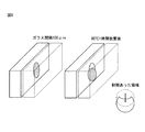
第1の実施形態における放熱用樹脂組成物又はその硬化物を用いる、シールド缶内への半導体素子の実装方法は、シールド缶及び電極を備える第1表面を有する基材と、電極を備える第1面及び該第1面と反対側の第2面とを有し、シールド缶内に配置される半導体素子とを、各第1表面が対向するように、アンダーフィル材料及び/又は導電部材を介して配置する工程(1)と、半導体素子の第2面に、放熱用樹脂組成物又はその硬化物である放熱用硬化物を適用する工程(2)と、加熱及び/又は加圧して半導体素子及び基材を接合する工程(3)であって、該工程(3)が、工程(1)又は工程(2)に続いて行われる、工程(3)と、適用した放熱用樹脂組成物又は放熱用硬化物上にシールド缶の蓋を配置し、必要に応じ、加熱及び/又は加圧する工程(4)と、工程(2)において放熱用樹脂組成物を使用する場合に、放熱用樹脂組成物を加熱又は電離放射線により硬化する工程(5)と、任意に、シールド缶の蓋及び半導体素子を取り外してリワークする工程(6)と、を備え、硬化する工程(5)が、工程(2)〜工程(4)の何れかで行われる。 A method of mounting a semiconductor element in a shielded can using the heat-dissipating resin composition or a cured product thereof according to the first embodiment is a method of mounting a semiconductor element in a shielded can, which comprises a base material having a first surface including a shielded can and an electrode, and a first electrode. A semiconductor element having a surface and a second surface opposite to the first surface and arranged in the shield can is interposed via an underfill material and / or a conductive member so that the first surfaces face each other. And the step (1) of applying the heat-dissipating resin composition or the cured product for heat dissipation to the second surface of the semiconductor element, and the step (2) of heating and / or pressurizing the semiconductor element. And the step (3) of joining the base materials, wherein the step (3) is performed following the step (1) or the step (2), the step (3) and the applied heat dissipation resin composition or When a shield can lid is placed on the heat-dissipating cured product and the heat-dissipating resin composition is used in the steps (4) and (2) of heating and / or pressurizing as necessary, the heat-dissipating resin composition. A step (5) of curing an object by heating or ionizing radiation and a step (6) of optionally removing the lid of a shield can and a semiconductor element and reworking the object are provided, and the step (5) of curing is a step (2). ) To step (4).
第1の実施形態における放熱用樹脂組成物又はその硬化物を用いる、筐体内への半導体素子の実装方法は、電極を備える第1表面を有する基材と、電極を備える第1面及び該第1面と反対側の第2面とを有する半導体素子とを、各第1表面が対向するように、アンダーフィル材料及び/又は導電部材を介して、必要に応じ、加熱及び/又は加圧して接合する工程(1)と、半導体素子の第2面に、放熱用樹脂組成物又はその硬化物である放熱用硬化物を適用する工程(2)と、適用した放熱用樹脂組成物又は放熱用硬化物上に筐体を配置し、必要に応じ、加熱及び/又は加圧して、放熱用樹脂組成物又は放熱用硬化物を半導体素子の前記第2面以上の面積に広げる工程(3)と、工程(2)において放熱用樹脂組成物を使用する場合に、放熱用樹脂組成物を加熱又は電離放射線により硬化する工程(4)と、任意に、筐体及び半導体素子を取り外してリワークする工程(5)と、を備え、硬化する工程(4)が、工程(2)〜工程(3)の何れかで行われる。 A method of mounting a semiconductor element in a housing using the heat-dissipating resin composition or a cured product thereof according to the first embodiment is a method of mounting a substrate having a first surface having electrodes, a first surface having electrodes, and the first surface thereof. A semiconductor device having a first surface and a second surface on the opposite side is heated and / or pressurized as necessary through an underfill material and / or a conductive member so that the first surfaces face each other. The step of joining (1), the step of applying the heat-dissipating resin composition or the cured product of the heat-dissipating resin composition to the second surface of the semiconductor element (2), and the applied heat-dissipating resin composition or heat-dissipating material. The step (3) of arranging the housing on the cured product and heating and / or pressurizing it as necessary to spread the heat-dissipating resin composition or the heat-dissipating cured product over the area of the second surface or more of the semiconductor element. When the heat-dissipating resin composition is used in the step (2), the heat-dissipating resin composition is cured by heating or ionizing radiation (4), and optionally, the housing and the semiconductor element are removed and reworked. The step (4) of comprising (5) and curing is performed in any one of steps (2) to (3).
これらの実装方法は、第1の実施形態における放熱用樹脂組成物又はその硬化物を用いているため、発熱量の大きい半導体素子等の部品から発生する熱を、基材、ヒートシンク、シールド缶の蓋、筐体等の物体に効果的に伝達して放熱し得ると共に、リレーやコネクターの接点不良等の不具合を低減させ、必要に応じてリワークすることができる。放熱用樹脂組成物の硬化物はゴム弾性を有さず塑性変形性を奏するため、変形に伴って生じる反作用の応力が弾性材料に比べて圧倒的に少ない。したがって、半導体部品、基材、ヒートシンク、シールド缶の蓋、筐体等に不要な応力を付加することがないため、製品性能の低下、外観不良等の問題を改善することができる。 Since these mounting methods use the heat-dissipating resin composition or a cured product thereof according to the first embodiment, heat generated from components such as semiconductor elements having a large calorific value is transferred to the base material, heat sink, and shield can. It can effectively transmit heat to objects such as lids and housings, reduce problems such as contact defects of relays and connectors, and rework as necessary. Since the cured product of the heat-dissipating resin composition does not have rubber elasticity and exhibits plastic deformability, the reaction stress generated by the deformation is overwhelmingly smaller than that of the elastic material. Therefore, since unnecessary stress is not applied to the semiconductor parts, the base material, the heat sink, the lid of the shield can, the housing, and the like, problems such as deterioration of product performance and poor appearance can be improved.
これらの実装方法は、第1の実施形態における放熱用樹脂組成物を基材等に適用する場合にディスペンサーを使用することができる。硬化前の放熱用樹脂組成物はディスペンサーを使用できる程度の高流動性の状態である。ディスペンサーの使用は、コンピューター制御及び局所部位への適用などが可能であるため、例えば、基板や半導体上の所望の位置にのみ放熱用樹脂組成物を塗布することができ、生産効率を大幅に向上させることができる。 In these mounting methods, a dispenser can be used when the heat-dissipating resin composition according to the first embodiment is applied to a base material or the like. The heat-dissipating resin composition before curing is in a state of high fluidity so that a dispenser can be used. Since the use of the dispenser can be controlled by a computer and applied to a local part, for example, the heat-dissipating resin composition can be applied only to a desired position on a substrate or a semiconductor, and the production efficiency is greatly improved. Can be made to.
以下、本発明の代表的な実施態様を例示する目的でより詳細に説明するが、本発明はこれらの実施態様に限定されない。 Hereinafter, the present invention will be described in more detail for the purpose of exemplifying typical embodiments of the present invention, but the present invention is not limited to these embodiments.
本開示において「オリゴマー」とは、少なくとも2個以上のモノマーが結合した重量平均分子量が約1万以下の重合体を意味する。 In the present disclosure, the "oligomer" means a polymer having at least two or more monomers bonded to each other and having a weight average molecular weight of about 10,000 or less.
本開示において「(メタ)アクリル」とはアクリル又はメタクリルを意味し、「(メタ)アクリレート」とはアクリレート又はメタクリレートを意味する。 In the present disclosure, "(meth) acrylic" means acrylic or methacrylic, and "(meth) acrylate" means acrylate or methacrylate.
本開示の一実施態様の放熱用樹脂組成物は、(A)成分:エポキシ樹脂、(B)成分:エポキシ樹脂用硬化剤、(C)成分:重量平均分子量約10000以下の(メタ)アクリルオリゴマー、及び(D)成分:熱伝導性粒子を含む。 The heat-dissipating resin composition according to one embodiment of the present disclosure includes (A) component: epoxy resin, (B) component: epoxy resin curing agent, and (C) component: (meth) acrylic oligomer having a weight average molecular weight of about 10,000 or less. , And (D) component: contains thermally conductive particles.
(A)成分のエポキシ樹脂としては、本技術分野で知られている任意のエポキシ樹脂を含んでいてよいが、熱伝導性粒子のバインダーとして機能するためには、常温で液状であることが望ましい。そのようなエポキシ樹脂は、硬化前25℃での粘度が、約0.1Pa・s以上、約0.5Pa・s以上、又は約1Pa・s以上、約200Pa・s以下、約150Pa・s以下、又は約100Pa・s以下であることが好ましい。エポキシ樹脂の粘度は、例えば、Brookfield回転粘度計を用いて測定することができる。 The epoxy resin of the component (A) may contain any epoxy resin known in the present technology, but in order to function as a binder for thermally conductive particles, it is desirable that the epoxy resin is liquid at room temperature. .. Such epoxy resins have viscosities at 25 ° C. before curing of about 0.1 Pa · s or more, about 0.5 Pa · s or more, or about 1 Pa · s or more, about 200 Pa · s or less, about 150 Pa · s or less. , Or about 100 Pa · s or less. The viscosity of the epoxy resin can be measured, for example, using a Brookfield rotational viscometer.
このような常温で液状のエポキシ樹脂として、重量平均分子量約200〜約500の、エピクロルヒドリンとビスフェノールA、F、AD等とから誘導されるビスフェノール型エポキシ樹脂;エピクロルヒドリンとフェノールノボラック又はクレゾールノボラックとから誘導されるエポキシノボラック樹脂;ナフタレン環を含んだ骨格を有するナフタレン型エポキシ樹脂;グリシジルアミン、グリシジルエーテル等のグリシジル基を、ビフェニル、ジシクロペンタジエン等の1分子内に2個以上有する、様々なエポキシ化合物;脂環エポキシ基を1分子内に2個以上有する脂環式エポキシ化合物、及びこれらの2種以上の混合物を使用してもよい。具体的には、例えば、エピコート(登録商標)EP828(ビスフェノールA型、エポキシ当量:190g/eq、ジャパンエポキシレジン社製)、YD128(ビスフェノールA型、エポキシ当量:184〜194g/eq、東都化成社製)、FDF−170(ビスフェノールF型、エポキシ当量:170g/eq、新日鉄住金化学社製)、エピコート(登録商標)EP807(ビスフェノールF型、ジャパンエポキシレジン社製)、EXA7015(水添ビスフェノールA型、DIC社製)、EP4088(ジシクロペンタジエン型、旭電化社製)、HP4032(ナフタレン型、DIC社製)、PLACCEL(登録商標) G402(ラクトン変性エポキシ、エポキシ当量:1050〜1450g/eq、ダイセル化学工業社製)、セロキサイド(登録商標)2021(脂環式、ダイセル化学工業社製)等を挙げることができる。本開示の放熱用樹脂組成物は、上記のようなエポキシ樹脂を1種類又は2種類以上混合して含んでいてもよい。 As such a liquid epoxy resin at room temperature, a bisphenol type epoxy resin derived from epichlorohydrin and bisphenol A, F, AD, etc. having a weight average molecular weight of about 200 to about 500; derived from epichlorohydrin and phenol novolac or cresol novolac. Epoxy novolak resin; Naphthalene-type epoxy resin having a skeleton containing a naphthalene ring; various epoxy compounds having two or more glycidyl groups such as glycidylamine and glycidyl ether in one molecule such as biphenyl and dicyclopentadiene. An alicyclic epoxy compound having two or more alicyclic epoxy groups in one molecule, and a mixture of two or more thereof may be used. Specifically, for example, Epicoat (registered trademark) EP828 (bisphenol A type, epoxy equivalent: 190 g / eq, manufactured by Japan Epoxy Resin Co., Ltd.), YD128 (bisphenol A type, epoxy equivalent: 184 to 194 g / eq, Toto Kasei Co., Ltd.) , FDF-170 (bisphenol F type, epoxy equivalent: 170 g / eq, manufactured by Nippon Steel & Sumitomo Metal Corporation), Epicoat (registered trademark) EP807 (bisphenol F type, manufactured by Japan Epoxy Resin), EXA7015 (hydrogenated bisphenol A type) , DIC), EP4088 (dicyclopentadiene type, Asahi Denka), HP4032 (naphthalen type, DIC), PLACCEL (registered trademark) G402 (lactone-modified epoxy, epoxy equivalent: 1050-1450 g / eq, Daisel (Chemical Industry Co., Ltd.), Epoxyside (registered trademark) 2021 (Alicyclic type, manufactured by Daicel Chemical Industry Co., Ltd.) and the like can be mentioned. The heat-dissipating resin composition of the present disclosure may contain one type or a mixture of two or more types of the above-mentioned epoxy resins.
(B)成分のエポキシ樹脂用硬化剤としては、重付加型硬化剤、触媒型硬化剤、縮合型硬化剤などが挙げられる。これらの硬化剤は、エポキシ樹脂の種類、硬化物の特性に応じて、1種類又は2種類以上組み合わせて使用することができる。 Examples of the curing agent for the epoxy resin of the component (B) include a polyaddition type curing agent, a catalytic type curing agent, and a condensation type curing agent. These curing agents can be used alone or in combination of two or more, depending on the type of epoxy resin and the characteristics of the cured product.
重付加型硬化剤として、例えばジエチレントリアミン(DETA)、トリエチレンテトラミン(TETA)、メタキシレリレンジアミン(MXDA)などの脂肪族ポリアミン、ジアミノジフェニルメタン(DDM)、m−フェニレンジアミン(MPDA)、ジアミノジフェニルスルホン(DDS)などの芳香族ポリアミン、ジシアンジアミド(DICY)、有機酸ジヒドラジドなどのポリアミン化合物;ヘキサヒドロ無水フタル酸(HHPA)、メチルテトラヒドロ無水フタル酸(MTHPA)などの脂環式酸無水物、無水トリメリット酸(TMA)、無水ピロメリット酸(PMDA)、ベンゾフェノンテトラカルボン酸(BTDA)などの芳香族酸無水物などを含む酸無水物;ノボラック型フェノール樹脂、フェノールポリマーなどのポリフェノール化合物;ポリスルフィド、チオエステル、チオエーテルなどのポリメルカプタン化合物;イソシアネートプレポリマー、ブロック化イソシアネートなどのイソシアネート化合物;カルボン酸含有ポリエステル樹脂などの有機酸類などが挙げられる。 Examples of the heavy addition type curing agent include aliphatic polyamines such as diethylenetriamine (DETA), triethylenetetramine (TETA), and metaxylerylene diamine (MXDA), diaminodiphenylmethane (DDM), m-phenylenediamine (MPDA), and diaminodiphenyl. Aromatic polyamines such as sulfone (DDS), polyamine compounds such as dicyandiamide (DICY) and organic acid dihydrazide; alicyclic acid anhydrides such as hexahydrophthalic anhydride (HHPA) and methyltetrahydrophthalic anhydride (MTHPA), trianhydrides. Acid anhydrides containing aromatic acid anhydrides such as merit acid (TMA), pyromellitic anhydride (PMDA), benzophenone tetracarboxylic acid (BTDA); polyphenol compounds such as novolak type phenol resin and phenol polymer; polysulfide, thioester , Polymercaptan compounds such as thioether; isocyanate compounds such as isocyanate prepolymer and blocked isocyanate; organic acids such as carboxylic acid-containing polyester resin and the like.
触媒型硬化剤として、例えば、ベンジルジメチルアミン(BDMA)、2,4,6−トリスジメチルアミノメチルフェノール(DMP−30)などの3級アミン化合物、2−メチルイミダゾール、2−エチル−4−メチルイミダゾール(EMI24)などのイミダゾール化合物、BF3錯体などのルイス酸などが挙げられる。 As catalytic curing agents, for example, tertiary amine compounds such as benzyldimethylamine (BDMA), 2,4,6-trisdimethylaminomethylphenol (DMP-30), 2-methylimidazole, 2-ethyl-4-methyl. Examples thereof include imidazole compounds such as imidazole (EMI24) and Lewis acids such as BF3 complex.
縮合型硬化剤として、例えば、レゾール型フェノール樹脂などのフェノール樹脂、メチロール基含有尿素樹脂のような尿素樹脂、メチロール基含有メラミン樹脂のようなメラミン樹脂等が挙げられる。 Examples of the condensation type curing agent include a phenol resin such as a resol type phenol resin, a urea resin such as a methylol group-containing urea resin, and a melamine resin such as a methylol group-containing melamine resin.
これらの硬化剤は、放熱用樹脂組成物の硬化性、硬化物の塑性変形性、リワーク性、放熱性などを考慮して、エポキシ樹脂成分100質量部に対して約0.1質量部以上、約1質量部以上、または約2質量部以上、約150質量部以下、約100質量部以下、約50質量部以下、約20質量部以下、約15質量部以下、または約10質量部以下の量で使用することができる。 Considering the curability of the heat-dissipating resin composition, the plastic deformability of the cured product, the reworkability, the heat-dissipating property, etc., these curing agents are about 0.1 part by mass or more with respect to 100 parts by mass of the epoxy resin component. About 1 part by mass or more, or about 2 parts by mass or more, about 150 parts by mass or less, about 100 parts by mass or less, about 50 parts by mass or less, about 20 parts by mass or less, about 15 parts by mass or less, or about 10 parts by mass or less. Can be used in quantity.
(B)成分のエポキシ樹脂用硬化剤は、潜在性硬化剤を使用することができる。潜在性硬化剤とは、常温では硬化性を発現せずに、放熱用樹脂組成物に含まれるエポキシ樹脂の硬化を進行させないが、加熱すると硬化性を発揮してエポキシ樹脂を所望の水準まで硬化させることが可能な硬化剤である。 As the curing agent for the epoxy resin of the component (B), a latent curing agent can be used. The latent curing agent does not exhibit curability at room temperature and does not proceed with curing of the epoxy resin contained in the heat-dissipating resin composition, but exhibits curability when heated and cures the epoxy resin to a desired level. It is a curing agent that can be made to grow.
使用可能な潜在性硬化剤として、イミダゾール、ヒドラジド等のヒドラジン類、三フッ化ホウ素−アミン錯体、アミンイミド、ポリアミン、第3級アミン、アルキル尿素等のアミン化合物、ジシアンジアミド、及びこれらの変性物、並びにこれら2種以上の混合物が挙げられる。 Possible latent curing agents include hydrazines such as imidazole and hydrazide, amine compounds such as boron trifluoride-amine complex, amineimide, polyamine, tertiary amine and alkylurea, dicyandiamide, and modifications thereof. Examples thereof include a mixture of two or more of these.
上述した潜在性硬化剤の中でも、イミダゾール潜在性硬化剤が好ましい。イミダゾール潜在性硬化剤としては、例えば、イミダゾール化合物とエポキシ樹脂との付加物を含んでもよく、そのようなイミダゾール化合物として、イミダゾール、2−メチルイミダゾール、2−エチルイミダゾール、2−プロピルイミダゾール、2−ドデシルイミダゾール、2−フェニルイミダゾール、2−フェニル−4−メチルイミダゾール、4−メチルイミダゾールが挙げられる。 Among the above-mentioned latent curing agents, the imidazole latent curing agent is preferable. The imidazole latent curing agent may include, for example, an adduct of an imidazole compound and an epoxy resin, and such imidazole compounds include imidazole, 2-methylimidazole, 2-ethylimidazole, 2-propylimidazole, 2-. Examples thereof include dodecylimidazole, 2-phenylimidazole, 2-phenyl-4-methylimidazole and 4-methylimidazole.
さらに、貯蔵安定性と短時間硬化性という相反する特性を両方とも高めるために、上述した潜在性硬化剤を核とし、ポリウレタン系、ポリエステル系等の高分子物質や、Ni、Cu等の金属薄膜等で被覆したカプセル化硬化剤を、本発明の潜在性硬化剤として使用してもよく、そのようなカプセル化硬化剤の中でも、カプセル化イミダゾールを使用することが好ましい。 Further, in order to enhance both the contradictory properties of storage stability and short-time curing property, the above-mentioned latent curing agent is used as a core, and polymer substances such as polyurethane and polyester and metal thin films such as Ni and Cu are used. An encapsulating curing agent coated with or the like may be used as the latent curing agent of the present invention, and among such encapsulating curing agents, it is preferable to use encapsulated imidazole.
このようなカプセル化イミダゾールとして、イミダゾール化合物を尿素やイソシアネート化合物でアダクトし、さらにその表面をイソシアネート化合物でブロックすることによりカプセル化したイミダゾール系潜在性硬化剤や、イミダゾール化合物をエポキシ化合物でアダクトし、さらにその表面をイソシアネート化合物でブロックすることによりカプセル化したイミダゾール系潜在性硬化剤を挙げることができる。具体的には、例えば、ノバキュア(登録商標)シリーズの、HX3941HP、HXA3042HP、HXA3922HP、HXA3792、HX3748、HX3721、HX3722、HX3088、HX3741、HX3742、HX3613等を挙げることができる。なお、ノバキュア(登録商標)はカプセル化イミダゾールと熱硬化性エポキシ樹脂とをある比率にて混合した製品である。 As such an encapsulated imidazole, an imidazole compound is adducted with urea or an isocyanate compound, and an imidazole-based latent curing agent encapsulated by blocking the surface with the isocyanate compound, or an imidazole compound is adducted with an epoxy compound. Further, an imidazole-based latent curing agent encapsulated by blocking the surface with an isocyanate compound can be mentioned. Specifically, for example, HX3941HP, HXA3042HP, HXA3922HP, HXA3792, HX3748, HX3721, HX3722, HX3088, HX3741, HX3742, HX3613 and the like of the Novacure (registered trademark) series can be mentioned. Novacure (registered trademark) is a product in which encapsulated imidazole and thermosetting epoxy resin are mixed in a certain ratio.
また、本発明に使用可能なアミン系潜在性硬化剤として、本技術分野で知られているアミン系潜在性硬化剤を含んでもよく、ポリアミン(例えば、H−4070S、H−3731S等、ACR社製)、第3級アミン(例えば、H3849S、ACR社製)、アルキル尿素(例えばH−3366S、ACR社製)等が挙げられる。 Further, as the amine-based latent curing agent that can be used in the present invention, an amine-based latent curing agent known in the present technology may be contained, and polyamines (for example, H-4070S, H-3731S, etc., ACR) may be included. ), Tertiary amines (eg, H3849S, manufactured by ACR), alkylureas (eg, H-3366S, manufactured by ACR) and the like.
潜在性硬化剤は、エポキシ樹脂成分100質量部に対して約1質量部以上、約10質量部以上、または約15質量部以上、約50質量部以下、約40質量部以下、または約30質量部以下の量で使用することができる。ここで、エポキシ樹脂と潜在性硬化剤との混合物の市販品を使用した場合、潜在性硬化剤の含有量とは、混合物中のエポキシ樹脂成分と他のエポキシ樹脂成分との合計質量を基準にした、混合物中に含まれる潜在性硬化剤成分の割合を指す。潜在性硬化剤の反応開始温度(又は活性温度とも呼ぶ)が高いほど放熱用樹脂組成物の貯蔵安定性が高くなり、反応開始温度が低いほど短時間で硬化させることができる。短時間硬化性と貯蔵安定性を可能な限り高い水準で両立させるために、潜在性硬化剤の反応開始温度は、約50℃以上、又は約100℃以上、約200℃以下、又は約180℃以下であることが好ましい。ここで、潜在性硬化剤の反応開始温度(活性温度)とは、DSC(示差走査熱量計)を用い、エポキシ樹脂と潜在性硬化剤との混合物を試料として室温から10℃/分で昇温させた時に得られるDSC曲線において、発熱量がピークの1/2となる低温側の温度での接線がベースラインと交わる点の温度と定義される。 The latent curing agent is about 1 part by mass or more, about 10 parts by mass or more, or about 15 parts by mass or more, about 50 parts by mass or less, about 40 parts by mass or less, or about 30 parts by mass with respect to 100 parts by mass of the epoxy resin component. It can be used in less than a part. Here, when a commercially available mixture of the epoxy resin and the latent curing agent is used, the content of the latent curing agent is based on the total mass of the epoxy resin component and the other epoxy resin components in the mixture. Refers to the ratio of the latent curing agent component contained in the mixture. The higher the reaction start temperature (also referred to as the activity temperature) of the latent curing agent, the higher the storage stability of the heat-dissipating resin composition, and the lower the reaction start temperature, the shorter the curing time. In order to achieve both short-time curing and storage stability at the highest possible level, the reaction initiation temperature of the latent curing agent is about 50 ° C. or higher, or about 100 ° C. or higher, about 200 ° C. or lower, or about 180 ° C. The following is preferable. Here, the reaction start temperature (active temperature) of the latent curing agent is raised at 10 ° C./min from room temperature using a DSC (differential scanning calorimetry) as a sample of a mixture of the epoxy resin and the latent curing agent. In the DSC curve obtained when the sample is used, it is defined as the temperature at which the tangent line at the temperature on the low temperature side where the calorific value is 1/2 of the peak intersects the baseline.
エポキシ樹脂を含む組成物は、硬化剤を用いるのに代えて又は硬化剤と共に、重合開始剤を含むことができ、電離放射線で光硬化させてもよい。電離放射線の種類については、特に制限はなく、X線、電子線、紫外線、可視光、赤外線などが挙げられるが、紫外線が広く用いられる。重合開始剤としてはカチオン重合性の開始剤が用いられる。光カチオン重合開始剤としては、特に限定されず、公知のものを使用することができ、たとえば、UCC社製「サイラキューアー(登録商標)UVI−6990、6974」、旭電化社製「アデカオプトマー(登録商標)SP−150、152、170、172」、ローディア社製「Photoinitiator 2074」、チバ・スペシャリティー社製「イルガキュアー(登録商標)250」、みどり化学社製「DTS−102」などが挙げられる。重合開始剤は、1種又は2種以上を組み合わせて使用できる。重合開始剤の使用量は、エポキシ樹脂に対して、約0.01質量%以上、又は約0.1質量%以上、10質量%以下、又は約5質量%以下とすることができる。 The composition containing the epoxy resin may contain a polymerization initiator instead of using a curing agent or together with the curing agent, and may be photocured by ionizing radiation. The type of ionizing radiation is not particularly limited, and examples thereof include X-rays, electron beams, ultraviolet rays, visible light, and infrared rays, but ultraviolet rays are widely used. As the polymerization initiator, a cationically polymerizable initiator is used. The photocationic polymerization initiator is not particularly limited, and known ones can be used. For example, "Cyracure (registered trademark) UVI-6990, 6974" manufactured by UCC and "Adekaopt" manufactured by Asahi Denka Co., Ltd. Ma (registered trademark) SP-150, 152, 170, 172 ”, Rhodia's“ Photoinitiator 2074 ”, Ciba Specialty's“ Irga Cure (registered trademark) 250 ”, Midori Kagaku's“ DTS-102 ”, etc. Can be mentioned. The polymerization initiator may be used alone or in combination of two or more. The amount of the polymerization initiator used can be about 0.01% by mass or more, or about 0.1% by mass or more, 10% by mass or less, or about 5% by mass or less with respect to the epoxy resin.
(C)成分の重量平均分子量10000以下の(メタ)アクリルオリゴマーは、(メタ)アクリロイル基を有する化合物を重合することによって得ることができる。(メタ)アクリロイル基を有する化合物としては、例えば(メタ)アクリレート系モノマーが挙げられる。具体的には、(メタ)アクリル酸アルキルエステルとして、(メタ)アクリル酸メチル、(メタ)アクリル酸エチル、(メタ)アクリル酸プロピル、(メタ)アクリル酸イソプロピル、(メタ)アクリル酸ブチル、(メタ)アクリル酸ペンチル、(メタ)アクリル酸ヘキシル、(メタ)アクリル酸2−エチルヘキシル、(メタ)アクリル酸オクチル、(メタ)アクリル酸ノニル、(メタ)アクリル酸ラウリル、(メタ)アクリル酸メトキシエチル、(メタ)アクリル酸メトキシブチル、(メタ)アクリル酸エトキシブチル、ポリエチレングリコール(メタ)アクリレート、メトキシポリエチレングリコール(メタ)アクリレート、フェノキシポリエチレングリコール(メタ)アクリレート、ポリエチレングリコールジ(メタ)アクリレート、エチレンオキサイド/テトラヒドロフラン共重合体の(メタ)アクリレート、エチレンオキサイド/プロピレンオキサイド共重合体の(メタ)アクリレート、ポリエチレングリコールモノアリルエーテル等が挙げられる。重合後の(メタ)アクリルオリゴマーのガラス転移温度(Tg)は、室温以下であることが好ましい。 The (meth) acrylic oligomer having a weight average molecular weight of 10,000 or less of the component (C) can be obtained by polymerizing a compound having a (meth) acryloyl group. Examples of the compound having a (meth) acryloyl group include (meth) acrylate-based monomers. Specifically, as the (meth) acrylic acid alkyl ester, methyl (meth) acrylate, ethyl (meth) acrylate, propyl (meth) acrylate, isopropyl (meth) acrylate, butyl (meth) acrylate, ( Pentyl acrylate, hexyl (meth) acrylate, 2-ethylhexyl (meth) acrylate, octyl (meth) acrylate, nonyl (meth) acrylate, lauryl (meth) acrylate, methoxyethyl (meth) acrylate , (Meta) methoxybutyl acrylate, (meth) ethoxybutyl acrylate, polyethylene glycol (meth) acrylate, methoxypolyethylene glycol (meth) acrylate, phenoxypolyethylene glycol (meth) acrylate, polyethylene glycol di (meth) acrylate, ethylene oxide (Meta) acrylate of / tetrahydrofuran copolymer, (meth) acrylate of ethylene oxide / propylene oxide copolymer, polyethylene glycol monoallyl ether and the like can be mentioned. The glass transition temperature (Tg) of the (meth) acrylic oligomer after polymerization is preferably room temperature or lower.
(C)成分の(メタ)アクリルオリゴマーは、カルボキシル基を含有してもよく、カルボキシル基を含有する(メタ)アクリルオリゴマーを(C−2)成分といい、カルボキシル基を有さない(メタ)アクリルオリゴマーを(C−1)成分という場合がある。カルボキシル基を有するモノマーとしては、例えば、(メタ)アクリル酸、カルボキシエチル(メタ)アクリレート、カルボキシペンチル(メタ)アクリレート等が挙げられる。これらのモノマーを1種又は2種以上、先の(メタ)アクリロイル基を有する化合物と共重合して(C−2)成分を得ることができる。(C−1)成分は、放熱用樹脂組成物及びその硬化物の疎水性、絶縁性を向上させることができ、(C−2)成分は、塩基性を呈する熱伝導性粒子の分散性、及び該粒子を含む放熱用樹脂組成物の流動性を向上させることができる。 The (meth) acrylic oligomer of the component (C) may contain a carboxyl group, and the (meth) acrylic oligomer containing a carboxyl group is called the (C-2) component and does not have a carboxyl group (meth). The acrylic oligomer may be referred to as the (C-1) component. Examples of the monomer having a carboxyl group include (meth) acrylic acid, carboxyethyl (meth) acrylate, and carboxypentyl (meth) acrylate. The component (C-2) can be obtained by copolymerizing one or more of these monomers with the above-mentioned compound having a (meth) acryloyl group. The component (C-1) can improve the hydrophobicity and insulating properties of the heat-dissipating resin composition and its cured product, and the component (C-2) can improve the dispersibility of the heat conductive particles exhibiting basicity. And the fluidity of the heat-dissipating resin composition containing the particles can be improved.
重合方法としては、特に限定されず、塊状(バルク)重合、溶液重合、乳化重合、懸濁重合など公知の方法を用いることができる。重合の方法によっては、開始剤、連鎖移動剤、乳化剤、懸濁剤など各種助剤を用いることができる。このうち、残留の不純物が少ないこと、オリゴマー領域の重量平均分子量の制御が容易なことから、塊状(バルク)重合、溶液重合が好ましい。 The polymerization method is not particularly limited, and known methods such as bulk polymerization, solution polymerization, emulsion polymerization, and suspension polymerization can be used. Depending on the polymerization method, various auxiliaries such as initiators, chain transfer agents, emulsifiers and suspending agents can be used. Of these, bulk polymerization and solution polymerization are preferable because there are few residual impurities and the weight average molecular weight of the oligomer region can be easily controlled.
(C)成分の(メタ)アクリルオリゴマーの重量平均分子量は、例えば、ポリスチレンを標準物質としたゲル浸透圧クロマトグラフィーにより求めることができる。(メタ)アクリルオリゴマーの重量平均分子量は約10000以下であれば、放熱用の材料として幅広く使用することができる。ディスペンサーへの適応性、塑性変形性、凝集性等を考慮した場合、重量平均分子量は、約100以上、約500以上、又は約1000以上、約10000以下、約8000以下、又は約5000以下が好ましい。 The weight average molecular weight of the (meth) acrylic oligomer of the component (C) can be determined, for example, by gel osmotic chromatography using polystyrene as a standard substance. When the weight average molecular weight of the (meth) acrylic oligomer is about 10,000 or less, it can be widely used as a material for heat dissipation. Considering adaptability to the dispenser, plastic deformability, cohesiveness, etc., the weight average molecular weight is preferably about 100 or more, about 500 or more, or about 1000 or more, about 10000 or less, about 8000 or less, or about 5000 or less. ..
ある実施態様では、放熱用樹脂組成物は、(A)〜(C)成分の重量分率(質量%)を、WA、WB及びWCとした場合、下記式(1)を満足させてもよい。(A)〜(C)成分の割合がこの範囲であると、硬化前の流動状態、ディスペンサーへの適応性、硬化後の塑性変形性、リワーク性等に優れる。
ある実施態様では、放熱用樹脂組成物は、(C−1)及び(C−2)成分の重量分率(質量%)をWC−1及びWC−2とした場合、下記式(2)を満足させてもよい。アルミナ等の無機粒子は一般的に塩基性を呈する。(C−2)成分のカルボキシル基を含有する(メタ)アクリルオリゴマーは塩基性を呈する無機粒子表面に結合するため、粒子の分散性が向上し、放熱用樹脂組成物全体の流動性も向上する。(C−2)成分の重量分率(WC−2)が0%の場合、放熱用樹脂組成物は粘度が上昇して固体化したり、エポキシ樹脂と(C−1)成分の相分離を生じさせる場合もある。したがって、(C−1)及び(C−2)成分の割合が下記式(2)を満足することが好ましい。
(C−2)成分であるカルボキシル基を含有する(メタ)アクリルオリゴマーの酸価は、約5mg KOH/g以上、約10mg KOH/g以上、又は約50mg KOH/g以上、約300mg KOH/g以下、約200mg KOH/g以下、又は約150mg KOH/g以下であってもよい。 The acid value of the (meth) acrylic oligomer containing a carboxyl group, which is a component of (C-2), is about 5 mg KOH / g or more, about 10 mg KOH / g or more, or about 50 mg KOH / g or more, about 300 mg KOH / g. Hereinafter, it may be about 200 mg KOH / g or less, or about 150 mg KOH / g or less.
放熱用樹脂組成物の(D)成分の熱伝導性粒子としては、絶縁性であっても導電性であってもよい。絶縁性の熱伝導性粒子としては、窒化ホウ素、窒化アルミニウム、窒化珪素等の窒素化合物や、酸化アルミニウム(アルミナ)、酸化マグネシウム、酸化亜鉛、酸化ケイ素、酸化ベリリウム、酸化チタン、酸化銅、亜酸化銅等の金属酸化物、水酸化マグネシウム、水酸化アルミニウム等の金属水酸化物、マグネサイト(炭酸マグネシウム)、炭化珪素、ダイアモンド等の炭素化合物、シリカ、タルク、マイカ、カオリン、ベントナイト、パイロフェライト等のセラミック類、ホウ化チタン、チタン酸カルシウム等が使用できる。 The thermally conductive particles of the component (D) of the heat-dissipating resin composition may be insulating or conductive. Insulating thermally conductive particles include nitrogen compounds such as boron nitride, aluminum nitride, and silicon nitride, aluminum oxide (alumina), magnesium oxide, zinc oxide, silicon oxide, berylium oxide, titanium oxide, copper oxide, and suboxide. Metal oxides such as copper, metal hydroxides such as magnesium hydroxide and aluminum hydroxide, carbon compounds such as magnesite (magnesium carbonate), silicon carbide and diamond, silica, talc, mica, kaolin, bentonite, pyroferrite and the like. Ceramics, titanium booxide, calcium titanate, etc. can be used.
これらの中でも、熱伝導性等の観点から、酸化アルミニウム(アルミナ)、水酸化アルミニウム、酸化亜鉛、窒化ホウ素、窒化アルミニウムが好ましい。なお、窒化ホウ素は、c−BN(立方晶構造)、w−BN(ウルツ鉱構造)、h−BN(六方晶構造)、r−BN(菱面体晶構造)、t−BN(乱層構造)等の何れの構造であってもよい。窒化ホウ素の形状には、球状のものと鱗片状のものがあるが、いずれも用いることができる。 Among these, aluminum oxide (alumina), aluminum hydroxide, zinc oxide, boron nitride, and aluminum nitride are preferable from the viewpoint of thermal conductivity and the like. Boron nitride contains c-BN (cubic structure), w-BN (Ultzite structure), h-BN (hexagonal structure), r-BN (diamond crystal structure), and t-BN (random layer structure). ) Etc. may be any structure. Boron nitride has a spherical shape and a scaly shape, and any of them can be used.
導電性の熱伝導性粒子としては、黒鉛、カーボンブラック、グラファイト、炭素繊維(ピッチ系、PAN系)、カーボンナノチューブ(CNT)、カーボンナノファイバー(CNF)等の炭素化合物や、銀、銅、鉄、ニッケル、アルミニウム、チタン等の金属又はこれらを含む金属合金、ステンレス(SUS)、異種元素がドープされた酸化亜鉛等の導電性金属酸化物、フェライト類等の金属系化合物が使用できる。導電性の熱伝導性粒子をシリカ等の絶縁性材料で被覆して絶縁性とし、これを熱伝導性粒子として使用することもできる。 The conductive heat conductive particles include carbon compounds such as graphite, carbon black, graphite, carbon fibers (pitch type, PAN type), carbon nanotubes (CNT), and carbon nanofibers (CNF), and silver, copper, and iron. , Metals such as nickel, aluminum and titanium or metal alloys containing these, stainless steel (SUS), conductive metal oxides such as zinc oxide doped with different elements, and metal compounds such as ferrites can be used. It is also possible to coat the conductive thermally conductive particles with an insulating material such as silica to make them insulating, and use these as the thermally conductive particles.
これらの熱伝導性粒子は、1種又は2種以上を組み合わせて使用できる。熱伝導性粒子の形状については、種々の形状のものを使用でき、例えば、繊維状、板状、鱗片状、棒状、粒状、ロッド状、チューブ状、曲板状、針状、曲板状、針状等が挙げられる。これらの熱伝導性粒子は、シランカップリング処理、チタネートカップリング処理、エポキシ処理、ウレタン処理、酸化処理等の表面処理が施されていてもよい。 These thermally conductive particles can be used alone or in combination of two or more. As the shape of the thermally conductive particles, various shapes can be used, for example, fibrous, plate-like, scaly, rod-like, granular, rod-like, tube-like, curved plate-like, needle-like, curved plate-like, and so on. Needle-shaped and the like can be mentioned. These thermally conductive particles may be subjected to surface treatment such as silane coupling treatment, titanate coupling treatment, epoxy treatment, urethane treatment, and oxidation treatment.
(D)成分である熱伝導性粒子の重量分率(質量%)をWDとした場合、下記式(3)を満足させてもよい。放熱性樹脂組成物の硬化前の流動性、放熱性等を考慮した場合、(D)成分の割合がこの範囲であることが好ましい。
熱伝導性粒子の平均粒子径は、0.1μm以上、0.2μm以上、又は0.3μm以上、100μm以下、70μm以下、又は50μmであってもよい。熱伝導性粒子は平均粒子径が異なる少なくとも2つの粒子を併用することができる。このような構成にすると、大きな粒子径の間に小さな粒子径の熱伝導性粒子が埋まり最密充填のような状態で充填されるため、熱伝導性が向上する。熱伝導性粒子の平均粒径、粒度分布は、電子顕微鏡、レーザー回折光散乱装置などにより測定することができる。また、例えば、平均粒子径が異なる2つの粒子を併用した場合、これらの粒子を含む放熱用樹脂組成物における粒度分布には2つのピークが観測される。したがって、放熱用樹脂組成物における粒度分布のピークの数を確認することで、平均粒子径の異なる粒子が放熱用樹脂組成物中にいくつ含まれているかを確認することができる。 The average particle size of the thermally conductive particles may be 0.1 μm or more, 0.2 μm or more, or 0.3 μm or more, 100 μm or less, 70 μm or less, or 50 μm. As the thermally conductive particles, at least two particles having different average particle diameters can be used in combination. With such a configuration, the thermally conductive particles having a small particle size are buried between the large particle diameters and are packed in a state such as closest packing, so that the thermal conductivity is improved. The average particle size and particle size distribution of the thermally conductive particles can be measured by an electron microscope, a laser diffracted light scattering device, or the like. Further, for example, when two particles having different average particle diameters are used in combination, two peaks are observed in the particle size distribution in the heat-dissipating resin composition containing these particles. Therefore, by confirming the number of peaks of the particle size distribution in the heat-dissipating resin composition, it is possible to confirm how many particles having different average particle diameters are contained in the heat-dissipating resin composition.
放熱用樹脂組成物は、難燃剤、顔料、染料、充填剤、補強材、レベリング剤、消泡剤、分散剤、硬化促進剤、反応性希釈剤、溶剤などの添加剤をさらに含んでもよい。これらの添加剤の配合量は、本発明の効果を損なわない範囲において適宜決定することができる。 The heat-dissipating resin composition may further contain additives such as flame retardants, pigments, dyes, fillers, reinforcing materials, leveling agents, defoamers, dispersants, curing accelerators, reactive diluents and solvents. The blending amount of these additives can be appropriately determined as long as the effects of the present invention are not impaired.
本開示の放熱用樹脂組成物は、加熱及び/又は電離放射線(X線、電子線、紫外線、可視光、赤外線など)によって硬化させることができる。硬化前の放熱用樹脂組成物は硬化後のものに比べて流動性が高いため、ディスペンサー等の塗布装置を使用することができる。一方、本開示の放熱用樹脂組成物は、(A)及び(B)成分に加えて(C)成分も含むので、硬化後は、硬化前に比べて低流動状態にはなるが、従来のエポキシ樹脂及び硬化剤を含む材料のようにゴム弾性及び高凝集力を呈する硬化物とはならず、塑性変形性及び適度な凝集力を呈する。このため本開示の放熱用樹脂組成物は、硬化後においても自由に硬化物の形状を変形、保持させることができ、必要に応じて除去することもできる。したがって、例えば、図1に示されるような半導体素子と基材との間への放熱用硬化物の形成において、放熱用樹脂組成物の硬化は、(a)〜(c)のいずれの工程で実施されてもよいが、別の製造ラインで放熱用樹脂組成物を硬化させて放熱用硬化物を作製しておき、その放熱用硬化物を半導体素子と基材との間に適用することもできる。必要に応じ、放熱用硬化物を介して貼り合わされた半導体部品や基材を取り外して、再利用(リワーク)することもできる。 The heat-dissipating resin composition of the present disclosure can be cured by heating and / or ionizing radiation (X-ray, electron beam, ultraviolet light, visible light, infrared light, etc.). Since the heat-dissipating resin composition before curing has higher fluidity than that after curing, a coating device such as a dispenser can be used. On the other hand, since the heat-dissipating resin composition of the present disclosure contains the component (C) in addition to the components (A) and (B), the flow state after curing is lower than that before curing, but it is conventional. Unlike a material containing an epoxy resin and a curing agent, it does not become a cured product exhibiting rubber elasticity and high cohesive force, but exhibits plastic deformability and moderate cohesive force. Therefore, the heat-dissipating resin composition of the present disclosure can freely deform and retain the shape of the cured product even after curing, and can be removed if necessary. Therefore, for example, in the formation of the heat-dissipating cured product between the semiconductor element and the base material as shown in FIG. 1, the heat-dissipating resin composition is cured in any of the steps (a) to (c). This may be carried out, but it is also possible to cure the heat-dissipating resin composition on another production line to prepare a heat-dissipating cured product, and apply the heat-dissipating cured product between the semiconductor element and the base material. it can. If necessary, the semiconductor parts and the base material bonded to each other via the heat-dissipating cured product can be removed and reused (reworked).
本開示の放熱用樹脂組成物、及び該組成物を硬化させた放熱用硬化物の放熱性能(熱伝導率)は、約1.0W/mK以上、又は約1.2W/mK以上にすることができる。 The heat dissipation performance (thermal conductivity) of the heat-dissipating resin composition of the present disclosure and the heat-dissipating cured product obtained by curing the composition shall be about 1.0 W / mK or more, or about 1.2 W / mK or more. Can be done.
以下、本発明の代表的な実施態様を例示する目的で、図面を参照しながらより詳細に説明するが、本発明はこれらの実施態様に限定されない。図面の参照番号について、異なる図面において類似する番号が付された要素は、類似又は対応する要素であることを示す。 Hereinafter, the present invention will be described in more detail with reference to the drawings for the purpose of exemplifying typical embodiments of the present invention, but the present invention is not limited to these embodiments. With respect to drawing reference numbers, elements with similar numbers in different drawings indicate similar or corresponding elements.
本開示の放熱用樹脂組成物の使用方法について図1〜4を参照しながら例示的に説明するが、放熱用樹脂組成物の使用方法はこれらに限られない。図1〜4はシリンジ方式のディスペンサーを使用した方法を例示する。 The method of using the heat-dissipating resin composition of the present disclosure will be exemplified with reference to FIGS. 1 to 4, but the method of using the heat-dissipating resin composition is not limited thereto. FIGS. 1 to 4 illustrate a method using a syringe type dispenser.
図1には、工程(a)〜工程(d)を備える、半導体素子の基材への実装方法が例示されている。工程(a)において、放熱用樹脂組成物を含むシリンジ100から、電極130を備える基材120上に放熱用樹脂組成物110を塗布する。ここで、加熱又は電離放射線を適用して放熱用樹脂組成物110を硬化させてもよい。工程(b)において、CMOSセンサー等の半導体素子150と基材120との間に放熱用樹脂組成物110が配置され、半導体素子150の電極(図示せず)と基材120の電極130とが半田や異方導電材等の導電部材140を介して接合されるように、半導体素子150を導電部材140を介して放熱用樹脂組成物110及び基材120上に配置する。工程(c)において、導電部材140に半田を使用する場合には、半田接続時の熱を利用して放熱用樹脂組成物110を加熱硬化させることができる。あるいは、半田接続時の熱を利用せずに、加熱又は電離放射線を別途適用して放熱用樹脂組成物110を硬化させてもよい。導電部材140に異方導電材を使用する場合には、加熱又は電離放射線を別途適用して放熱用樹脂組成物110を硬化させることができる。ここで工程(c)において、必要に応じ、加圧を適用してもよい。任意に、工程(d)において、加熱して半田を融解し、真空チャック等の引き上げ手段160を用いて半導体素子150を引き上げることで半導体素子150と基材120とを取り外して、これらの部材を再利用(リワーク)することができる。
FIG. 1 illustrates a method of mounting a semiconductor element on a substrate, which comprises steps (a) to (d). In the step (a), the heat radiating
図2には、工程(a)〜工程(d)を備える、半導体素子及びヒートシンクの実装方法が例示されている。工程(a)において、電極(図示せず)を備える第1表面を有する基材220と、電極(図示せず)を備える第1面及び該第1面と反対側の第2面とを有する半導体素子250とを、両部材の各第1表面が対向するように、アンダーフィル材料245及び/又は半田ボールや異方導電材等の導電部材235を介して配置し、続いて、放熱用樹脂組成物を含むシリンジ200から、半導体素子250の第2面上に放熱用樹脂組成物210を塗布する。ここで、加熱又は電離放射線を適用して放熱用樹脂組成物210を硬化させてもよい。工程(b)において、アンダーフィル材料245、導電部材235として半田ボールを使用する場合には、アンダーフィル材料の硬化、半田接続時の熱を利用して放熱用樹脂組成物210を加熱硬化させることができる。あるいは、アンダーフィル材料の硬化、半田接続時の熱を利用せずに、加熱又は電離放射線を別途適用して放熱用樹脂組成物210を硬化させてもよい。アンダーフィル材料を使用せず、導電部材として異方導電材を使用する場合には、加熱又は電離放射線を別途適用して放熱用樹脂組成物210を硬化させることができる。ここで工程(b)において、必要に応じ、加圧を適用してもよい。工程(c)において、適用した放熱用樹脂組成物210上にヒートシンク255を配置し、必要に応じ、加熱及び/又は加圧する。ヒートシンク255の配置において、加熱又は電離放射線を適用して放熱用樹脂組成物210を硬化させてもよい。任意に、工程(d)において、ヒートシンク255を引き上げることでヒートシンク255と半導体素子150を含む他の部材とを取り外して、これらの部材を再利用(リワーク)することができる。
FIG. 2 illustrates a method of mounting a semiconductor element and a heat sink, which comprises steps (a) to (d). In step (a), it has a
図3には、工程(a)〜工程(c)を備える、シールド缶内への半導体素子の実装方法が例示されている。工程(a)において、コンデンサ365、シールド缶370及び電極(図示せず)を備える第1表面を有する基材320と、電極(図示せず)を備える第1面及び該第1面と反対側の第2面とを有する半導体素子350とを、両部材の各第1表面が対向するように、アンダーフィル材料345及び/又は半田ボールや異方導電材等の導電部材335を介して配置し、続いて、放熱用樹脂組成物を含むシリンジ300から、半導体素子350の第2面上に放熱用樹脂組成物310を塗布する。ここで、加熱又は電離放射線を適用して放熱用樹脂組成物310を硬化させてもよい。工程(b)において、アンダーフィル材料345、導電部材335として半田ボールを使用する場合には、アンダーフィル材料の硬化、半田接続時の熱を利用して放熱用樹脂組成物310を加熱硬化させることができる。あるいは、アンダーフィル材料の硬化、半田接続時の熱を利用せずに、加熱又は電離放射線を別途適用して放熱用樹脂組成物310を硬化させてもよい。アンダーフィル材料を使用せず、導電部材として異方導電材を使用する場合には、加熱又は電離放射線を別途適用して放熱用樹脂組成物310を硬化させることができる。続いて、放熱用樹脂組成物310上にシールド缶の蓋375を配置し、必要に応じ、加熱及び/又は加圧する。放熱用樹脂組成物310はこのときに、加熱又は電離放射線を適用して硬化させてもよい。任意に、工程(c)において、シールド缶の蓋375を引き上げることでシールド缶の蓋375と半導体素子350を含む他の部材とを取り外して、これらの部材を再利用(リワーク)することができる。
FIG. 3 illustrates a method of mounting a semiconductor element in a shielded can, which comprises steps (a) to (c). In step (a), a
図4には、工程(a)及び工程(b)を備える、筐体内への半導体素子の実装方法が例示されている。工程(a)において、コンデンサ465及び電極(図示せず)を備える第1表面を有する基材420と、電極(図示せず)を備える第1面及び該第1面と反対側の第2面とを有する半導体素子450とを、両部材の各第1表面が対向するように、アンダーフィル材料445及び/又は半田ボールや異方導電材等の導電部材435を介して配置し加熱及び/又は加圧して接合し、続いて、放熱用樹脂組成物を含むシリンジ400から、半導体素子450の第2面上に放熱用樹脂組成物410を多量に塗布する。塗布した放熱用樹脂組成物410に加熱又は電離放射線を適用して硬化させることができる。工程(b)において、放熱用樹脂組成物410上に筐体480を配置し、必要に応じ、加熱及び/又は加圧して、放熱用樹脂組成物410を半導体素子450の第2面以上の面積に広げる。放熱用樹脂組成物410はこのときに、加熱又は電離放射線を適用して硬化させてもよい。図示してはいないが、必要に応じ、筐体480を引き上げるなどして筐体480と半導体素子450を含む他の部材とを取り外して、これらの部材を再利用(リワーク)することができる。この例示態様のように、放熱用樹脂組成物の硬化物が半導体素子を超えて横に広げられた場合には、該硬化物と筐体との接触面積が増大するため、半導体素子等の発熱部品からの熱を筐体の広い面積に分散させることができ、筐体温度の局所的な上昇を緩和することができる。
FIG. 4 illustrates a method of mounting a semiconductor element in a housing, which comprises steps (a) and (b). In step (a), a
以下の実施例において、本開示の具体的な実施態様を例示するが、本発明はこれに限定されるものではない。部及びパーセントは全て、特に明記しない限り質量による。 The following examples exemplify specific embodiments of the present disclosure, but the present invention is not limited thereto. All parts and percentages are by mass unless otherwise stated.
本実施例で使用した原料などを以下の表1に示す。 The raw materials used in this example are shown in Table 1 below.
<評価方法>
本開示の放熱用樹脂組成物及びその硬化物である放熱用硬化物の特性を以下の方法にしたがって評価した。
<Evaluation method>
The characteristics of the heat-dissipating resin composition of the present disclosure and the cured product for heat dissipation, which is a cured product thereof, were evaluated according to the following method.
<硬化後の樹脂流動性>
図5に示すように、アルミ板(60mm×30mm×1mm)上に放熱用樹脂組成物を直径6.0mm、厚さ180μmとなるように塗布し、オーブン内で150℃20分間放置して加熱硬化させた。硬化した放熱用硬化物上にガラス板(18mm×18mm×0.3mm)を置き、その上に4kgの分銅を載せ、80℃のオーブン内で20分間放置した。放置後の放熱用硬化物の直径を測定し、直径が6.1mm未満を不良「×」、6.1mm以上、7.0mm未満を良「△」、7.0mm以上を優良「○」と判定した。
<Resin fluidity after curing>
As shown in FIG. 5, a heat-dissipating resin composition is applied onto an aluminum plate (60 mm × 30 mm × 1 mm) so as to have a diameter of 6.0 mm and a thickness of 180 μm, and left in an oven at 150 ° C. for 20 minutes for heating. It was cured. A glass plate (18 mm × 18 mm × 0.3 mm) was placed on the cured cured product for heat dissipation, a weight of 4 kg was placed on the glass plate (18 mm × 18 mm × 0.3 mm), and the mixture was left in an oven at 80 ° C. for 20 minutes. Measure the diameter of the cured product for heat dissipation after leaving it, and if the diameter is less than 6.1 mm, it is rated as defective "x", if it is 6.1 mm or more and less than 7.0 mm, it is marked as good "△", and if it is 7.0 mm or more, it is marked as excellent "○". Judged.
<硬化後の耐流れ出し性>
図6に示すように、第1のガラス板(76mm×26mm×1mm)の上に放熱用樹脂組成物を塗布し、スペーサーとなる両面テープを備える第2のガラス板を塗布した放熱用樹脂組成物に対して押し付けて、該組成物の直径が15mm、厚さが100μmになるようなサンプルを作製した。放熱用樹脂組成物をオーブン内で150℃20分間放置して加熱硬化させた後、ガラス面を鉛直方向に向けて80℃のオーブン内で1時間放置し、初期に存在していた領域から放熱用硬化物がどれだけ残留しているかを測定した。放熱用硬化物の残留率が70%未満を不良「×」、70%以上85%未満を良「△」、85%以上を優良「○」と判定した。
<Flow resistance after curing>
As shown in FIG. 6, a heat-dissipating resin composition is coated on a first glass plate (76 mm × 26 mm × 1 mm), and a second glass plate provided with a double-sided tape serving as a spacer is coated. A sample was prepared by pressing against an object so that the composition had a diameter of 15 mm and a thickness of 100 μm. The heat-dissipating resin composition was left in the oven at 150 ° C. for 20 minutes to be heat-cured, and then left in the oven at 80 ° C. for 1 hour with the glass surface facing vertically to dissipate heat from the initially existing region. The amount of the cured product remaining was measured. A residual rate of the cured product for heat dissipation of less than 70% was judged as defective "x", 70% or more and less than 85% was judged as good "Δ", and 85% or more was judged as excellent "○".
<初期流動性(ディスペンス性)>
放熱用樹脂組成物をシリンジ(PSY−10E、武蔵エンジアリング社製)に入れ、内径0.4mmの針(23G)を取りつけて、エアーディスペンサー(SuperΣx、武蔵エンジニアリング社製)を使用してエアー圧0.3MPaで加圧した。ディスペンサーで放熱用樹脂組成物を押し出せたものを合格「○」、押し出せなかったものを不合格「×」と判定した。
<Initial fluidity (dispensability)>
Put the heat-dissipating resin composition in a syringe (PSY-10E, manufactured by Musashi Engineering Co., Ltd.), attach a needle (23G) with an inner diameter of 0.4 mm, and use an air dispenser (SuperΣx, manufactured by Musashi Engineering Co., Ltd.) to air pressure. Pressurized at 0.3 MPa. Those that could extrude the heat-dissipating resin composition with the dispenser were judged as "○", and those that could not be extruded were judged as "×".
<熱抵抗測定>
アルミ製ヒートシンク(46.2mm×50mm×21mm、フィン数10枚、フィン厚1.2mm, フィンとフィンの間隔3.8mm,ベース部の厚み2.75mm)に放熱用樹脂組成物を30μmの厚さで塗布し、オーブン内で150℃20分間放置して加熱硬化させ、大電力抵抗測定モジュール(型番:AE−RA1WX16−1R00、秋月電子社製)1Ω(16W)を貼り付け、電圧10V、電流3Aで通電した。ヒートシンクをファンで冷却しながら、ヒートシンクと大電力抵抗モジュールのメタル基板との温度を測定し、定常状態になった際の温度差ΔTを測定した。参考例として、信越シリコーン社製のオイルコンパウンドG−775(3.6W/mK)を用いて同様の測定を行った。
<Measurement of thermal resistance>
A heat-dissipating resin composition having a thickness of 30 μm is applied to an aluminum heat sink (46.2 mm × 50 mm × 21 mm, number of fins 10 sheets, fin thickness 1.2 mm, fin-to-fin spacing 3.8 mm, base thickness 2.75 mm). Apply with a heat sink, leave in an oven at 150 ° C for 20 minutes to cure by heating, attach a high power resistance measurement module (model number: AE-RA1WX16-1R00, manufactured by Akizuki Denshi Co., Ltd.) 1Ω (16W), voltage 10V, current It was energized at 3A. While cooling the heat sink with a fan, the temperature between the heat sink and the metal substrate of the high power resistance module was measured, and the temperature difference ΔT when the state became steady was measured. As a reference example, the same measurement was carried out using an oil compound G-775 (3.6 W / mK) manufactured by Shinetsu Silicone Co., Ltd.
<例1〜9、比較例1>
自転・公転ミキサーのあわとり練太郎(登録商標)ARE−310(シンキー社製)を使用し、表1の原料を表2の組成比で各々混合した。
<Examples 1 to 9, Comparative Example 1>
Using a rotation / revolution mixer, Awatori Rentaro (registered trademark) ARE-310 (manufactured by Shinky Co., Ltd.), the raw materials in Table 1 were mixed at the composition ratios in Table 2.
得られた放熱用樹脂組成物における、硬化後の樹脂流動性及び耐流れ出し性、並びに初期流動性(ディスペンス性)の結果を表3に示し、熱抵抗測定の結果を表4に示す。なお、初期流動性(ディスペンス性)は、ディスペンサーを要する場合に必要な特性であり、必須の特性ではない。 Table 3 shows the results of the resin fluidity and outflow resistance after curing and the initial fluidity (dispensability) of the obtained heat-dissipating resin composition, and Table 4 shows the results of thermal resistance measurement. The initial fluidity (dispensability) is a characteristic required when a dispenser is required, and is not an essential characteristic.
100、200、300、400 シリンジ
110、210、310、410 放熱用樹脂組成物
120、220、320、420 基材
130 電極
140 導電部材
150、250、350、450 半導体素子
160 引き上げ手段
235、335、435 導電部材
245、345、445 アンダーフィル材料
255 ヒートシンク
365、465 コンデンサ
370 シールド缶
375 シールド缶の蓋
480 筐体
本開示の実施態様の一部を以下の[項目1]−[項目12]に記載する。
[項目1]
(A)成分:エポキシ樹脂、(B)成分:エポキシ樹脂用硬化剤、(C)成分:重量平均分子量10000以下の(メタ)アクリルオリゴマー、及び(D)成分:熱伝導性粒子を含む、放熱用樹脂組成物。
[項目2]
(C)成分が、(C−1)成分:カルボキシル基を有さない重量平均分子量10000以下の(メタ)アクリルオリゴマー及び/又は(C−2)成分:カルボキシル基を有する重量平均分子量10000以下の(メタ)アクリルオリゴマーである、項目1記載の放熱用樹脂組成物。
[項目3]
(A)〜(C)成分の重量分率を、W A 、W B 及びW C とした場合、下記式(1)を満足する、項目1又は2記載の放熱用樹脂組成物。
(C−1)及び(C−2)成分の重量分率をW C−1 及びW C−2 とした場合、下記式(2)を満足する、項目2又は3記載の放熱用樹脂組成物。
(D)成分の重量分率をW D とした場合、下記式(3)を満足する、項目1〜4の何れか一項に記載の放熱用樹脂組成物。
項目1〜5の何れか一項に記載の放熱用樹脂組成物を硬化した放熱用硬化物。
[項目7]
塑性変形を呈する、項目6記載の放熱用硬化物。
[項目8]
項目1〜5の何れか一項に記載の放熱用樹脂組成物又は項目6若しくは7記載の放熱用硬化物を、電極を備える基材に適用する工程(1)と、
適用した放熱用樹脂組成物又は放熱用硬化物上に電極を備える半導体素子を配置し、必要に応じ、加熱及び/又は加圧する工程(2)であって、基材及び半導体素子の電極が導電部材を介して接合される、工程(2)と、
前記工程(1)において放熱用樹脂組成物を使用する場合に、該放熱用樹脂組成物を加熱又は電離放射線により硬化する工程(3)と、
任意に、基材及び半導体素子を取り外してリワークする工程(4)と、を備える、半導体素子の実装方法であって、前記硬化する工程(3)が、工程(1)〜工程(2)の何れかで行われる、半導体素子の実装方法。
[項目9]
電極を備える第1表面を有する基材と、電極を備える第1面及び該第1面と反対側の第2面とを有する半導体素子とを、前記各第1表面が対向するように、アンダーフィル材料及び/又は導電部材を介して配置する工程(1)と、
半導体素子の前記第2面に、項目1〜5の何れか一項に記載の放熱用樹脂組成物又は項目6若しくは7記載の放熱用硬化物を適用する工程(2)と、
加熱及び/又は加圧して半導体素子及び基材を接合する工程(3)であって、該工程(3)が、前記工程(1)又は工程(2)に続いて行われる、工程(3)と、
適用した放熱用樹脂組成物又は放熱用硬化物上にヒートシンクを配置し、必要に応じ、加熱及び/又は加圧する工程(4)と、
前記工程(2)において放熱用樹脂組成物を使用する場合に、該放熱用樹脂組成物を加熱又は電離放射線により硬化する工程(5)と、
任意に、ヒートシンク及び半導体素子を取り外してリワークする工程(6)と、を備える、半導体素子及びヒートシンクの実装方法であって、前記硬化する工程(5)が、工程(2)〜工程(4)の何れかで行われる、半導体素子及びヒートシンクの実装方法。
[項目10]
シールド缶及び電極を備える第1表面を有する基材と、電極を備える第1面及び該第1面と反対側の第2面とを有し、前記シールド缶内に配置される半導体素子とを、前記各第1表面が対向するように、アンダーフィル材料及び/又は導電部材を介して配置する工程(1)と、
半導体素子の前記第2面に、項目1〜5の何れか一項に記載の放熱用樹脂組成物又は項目6若しくは7記載の放熱用硬化物を適用する工程(2)と、
加熱及び/又は加圧して半導体素子及び基材を接合する工程(3)であって、該工程(3)が、前記工程(1)又は工程(2)に続いて行われる、工程(3)と、
適用した放熱用樹脂組成物又は放熱用硬化物上にシールド缶の蓋を配置し、必要に応じ、加熱及び/又は加圧する工程(4)と、
前記工程(2)において放熱用樹脂組成物を使用する場合に、該放熱用樹脂組成物を加熱又は電離放射線により硬化する工程(5)と、
任意に、シールド缶の蓋及び半導体素子を取り外してリワークする工程(6)と、を備える、シールド缶内への半導体素子の実装方法であって、前記硬化する工程(5)が、工程(2)〜工程(4)の何れかで行われる、シールド缶内への半導体素子の実装方法。
[項目11]
電極を備える第1表面を有する基材と、電極を備える第1面及び該第1面と反対側の第2面とを有する半導体素子とを、前記各第1表面が対向するように、アンダーフィル材料及び/又は導電部材を介して加熱及び/又は加圧して接合する工程(1)と、
半導体素子の前記第2面に、項目1〜5の何れか一項に記載の放熱用樹脂組成物又は項目6若しくは7記載の放熱用硬化物を適用する工程(2)と、
適用した放熱用樹脂組成物又は放熱用硬化物上に筐体を配置し、必要に応じ、加熱及び/又は加圧して、放熱用樹脂組成物又は放熱用硬化物を半導体素子の前記第2面以上の面積に広げる工程(3)と、
前記工程(2)において放熱用樹脂組成物を使用する場合に、該放熱用樹脂組成物を加熱又は電離放射線により硬化する工程(4)と、
任意に、筐体及び半導体素子を取り外してリワークする工程(5)と、を備える、筐体内への半導体素子の実装方法であって、前記硬化する工程(4)が、工程(2)〜工程(3)の何れかで行われる、筐体内への半導体素子の実装方法。
[項目12]
放熱用樹脂組成物を適用する場合に、ディスペンサーを使用する、項目8〜11の何れか一項に記載の実装方法。
100, 200, 300, 400
A part of the embodiments of the present disclosure will be described in the following [Item 1]-[Item 12].
[Item 1]
(A) component: epoxy resin, (B) component: curing agent for epoxy resin, (C) component: (meth) acrylic oligomer having a weight average molecular weight of 10,000 or less, and (D) component: heat dissipation containing thermally conductive particles Resin composition for.
[Item 2]
The component (C) is a (C-1) component: a (meth) acrylic oligomer having a weight average molecular weight of 10,000 or less without a carboxyl group and / or a component (C-2): a weight average molecular weight of 10,000 or less having a carboxyl group. The heat-dissipating resin composition according to item 1, which is a (meth) acrylic oligomer.
[Item 3]
The weight fraction of (A) ~ (C) component, W A, when a W B and W C, satisfy the following formula (1), item 1 or 2 radiating resin composition.
The heat-dissipating resin composition according to item 2 or 3, which satisfies the following formula (2) when the weight fractions of the components (C-1) and (C-2) are WC -1 and WC -2. ..
(D) If the weight fraction of component a W D, satisfying the following formula (3), radiating the resin composition according to any one of items 1-4.
A heat-dissipating cured product obtained by curing the heat-dissipating resin composition according to any one of items 1 to 5.
[Item 7]
Item 6. The heat-dissipating cured product according to item 6, which exhibits plastic deformation.
[Item 8]
The step (1) of applying the heat-dissipating resin composition according to any one of items 1 to 5 or the heat-dissipating cured product according to item 6 or 7 to a base material provided with electrodes.
In the step (2) of arranging a semiconductor element having an electrode on the applied heat-dissipating resin composition or heat-dissipating cured product and heating and / or pressurizing as necessary, the base material and the electrodes of the semiconductor element are conductive. Step (2), which is joined via members,
When the heat-dissipating resin composition is used in the step (1), the step (3) of curing the heat-dissipating resin composition by heating or ionizing radiation.
A method for mounting a semiconductor element, comprising a step (4) of optionally removing a base material and a semiconductor element and reworking, wherein the curing step (3) is a step (1) to a step (2). A method of mounting a semiconductor element, which is performed by either method.
[Item 9]
A base material having a first surface having an electrode and a semiconductor element having a first surface having an electrode and a second surface opposite to the first surface are undersized so that the first surfaces face each other. The step (1) of arranging through the fill material and / or the conductive member, and
The step (2) of applying the heat-dissipating resin composition according to any one of items 1 to 5 or the heat-dissipating cured product according to item 6 or 7 to the second surface of the semiconductor element.
A step (3) of heating and / or pressurizing to join a semiconductor element and a base material, wherein the step (3) is performed following the step (1) or the step (2). When,
A step (4) of arranging a heat sink on the applied heat-dissipating resin composition or heat-dissipating cured product, and heating and / or pressurizing as necessary.
When the heat-dissipating resin composition is used in the step (2), the step (5) of curing the heat-dissipating resin composition by heating or ionizing radiation.
A method for mounting a semiconductor element and a heat sink, further comprising a step (6) of optionally removing and reworking the heat sink and the semiconductor element, wherein the curing step (5) includes steps (2) to (4). A method for mounting a semiconductor element and a heat sink, which is performed in any of the above.
[Item 10]
A base material having a first surface having a shield can and an electrode, and a semiconductor element having a first surface having an electrode and a second surface opposite to the first surface and arranged in the shield can. The step (1) of arranging the first surfaces with the underfill material and / or the conductive member so as to face each other.
The step (2) of applying the heat-dissipating resin composition according to any one of items 1 to 5 or the heat-dissipating cured product according to item 6 or 7 to the second surface of the semiconductor element.
A step (3) of heating and / or pressurizing to join a semiconductor element and a base material, wherein the step (3) is performed following the step (1) or the step (2). When,
The step (4) of arranging the lid of the shield can on the applied heat-dissipating resin composition or heat-dissipating cured product, and heating and / or pressurizing as necessary.
When the heat-dissipating resin composition is used in the step (2), the step (5) of curing the heat-dissipating resin composition by heating or ionizing radiation.
A method of mounting a semiconductor element in a shield can, further comprising a step (6) of optionally removing and reworking the lid of the shield can and the semiconductor element, wherein the curing step (5) is a step (2). ) To the method for mounting the semiconductor element in the shield can, which is performed in any of the steps (4).
[Item 11]
A base material having a first surface having an electrode and a semiconductor element having a first surface having an electrode and a second surface opposite to the first surface are underlaid so that the first surfaces face each other. The step (1) of heating and / or pressurizing and joining via a fill material and / or a conductive member, and
The step (2) of applying the heat-dissipating resin composition according to any one of items 1 to 5 or the heat-dissipating cured product according to item 6 or 7 to the second surface of the semiconductor element.
The housing is placed on the applied heat-dissipating resin composition or heat-dissipating cured product, and if necessary, heated and / or pressurized to apply the heat-dissipating resin composition or heat-dissipating cured product to the second surface of the semiconductor element. Step (3) to expand to the above area and
When the heat-dissipating resin composition is used in the step (2), the step (4) of curing the heat-dissipating resin composition by heating or ionizing radiation.
A method of mounting a semiconductor element in a housing, further comprising a step (5) of optionally removing and reworking the housing and the semiconductor element, wherein the curing step (4) is a step (2) to a step. A method for mounting a semiconductor element in a housing, which is performed by any of (3).
[Item 12]
The mounting method according to any one of items 8 to 11, wherein a dispenser is used when the heat-dissipating resin composition is applied.
Claims (8)
(A)〜(C)成分の重量分率を、WA、WB及びWCとした場合、下記式(1)を満足し、
前記放熱用樹脂組成物は、前記エポキシ樹脂硬化剤を、前記エポキシ樹脂100質量部に対し、0.1質量部以上、150質量部以下含み、
前記放熱用樹脂組成物を硬化させたときに、塑性変形を呈する、
放熱用樹脂組成物。
(A) ~ a weight fraction of component (C), when the W A, W B and W C, satisfies the following formula (1),
The heat-dissipating resin composition contains the epoxy resin curing agent in an amount of 0.1 part by mass or more and 150 parts by mass or less with respect to 100 parts by mass of the epoxy resin.
When the heat-dissipating resin composition is cured, it exhibits plastic deformation.
Resin composition for heat dissipation.
(C−1)及び(C−2)成分の重量分率をWC−1及びWC−2とした場合、下記式(2)を満足する、請求項1に記載の放熱用樹脂組成物。
The heat-dissipating resin composition according to claim 1, which satisfies the following formula (2) when the weight fractions of the components (C-1) and (C-2) are WC -1 and WC -2. ..
適用した放熱用樹脂組成物又は放熱用硬化物上に電極を備える半導体素子を配置し、必要に応じ、加熱及び/又は加圧する工程(2)であって、基材及び半導体素子の電極が導電部材を介して接合される、工程(2)と、
前記工程(1)において放熱用樹脂組成物を使用する場合に、該放熱用樹脂組成物を加熱又は電離放射線により硬化する工程(3)と、
任意に、基材及び半導体素子を取り外してリワークする工程(4)と、を備える、半導体素子の実装方法であって、前記硬化する工程(3)が、工程(1)〜工程(2)の何れかで行われる、半導体素子の実装方法。 A step (1) of applying the heat-dissipating resin composition according to any one of claims 1 to 3 or the heat-dissipating cured product according to claim 4 to a base material provided with electrodes.
In the step (2) of arranging a semiconductor element having an electrode on the applied heat-dissipating resin composition or heat-dissipating cured product and heating and / or pressurizing as necessary, the base material and the electrodes of the semiconductor element are conductive. Step (2), which is joined via members,
When the heat-dissipating resin composition is used in the step (1), the step (3) of curing the heat-dissipating resin composition by heating or ionizing radiation.
A method for mounting a semiconductor element, comprising a step (4) of optionally removing a base material and a semiconductor element and reworking, wherein the curing step (3) is a step (1) to a step (2). A method of mounting a semiconductor element, which is performed by either method.
半導体素子の前記第2面に、請求項1〜3の何れか一項に記載の放熱用樹脂組成物又は請求項4に記載の放熱用硬化物を適用する工程(2)と、
加熱及び/又は加圧して半導体素子及び基材を接合する工程(3)であって、該工程(3)が、前記工程(1)又は工程(2)に続いて行われる、工程(3)と、
適用した放熱用樹脂組成物又は放熱用硬化物上にヒートシンクを配置し、必要に応じ、加熱及び/又は加圧する工程(4)と、
前記工程(2)において放熱用樹脂組成物を使用する場合に、該放熱用樹脂組成物を加熱又は電離放射線により硬化する工程(5)と、
任意に、ヒートシンク及び半導体素子を取り外してリワークする工程(6)と、を備える、半導体素子及びヒートシンクの実装方法であって、前記硬化する工程(5)が、工程(2)〜工程(4)の何れかで行われる、半導体素子及びヒートシンクの実装方法。 A base material having a first surface having an electrode and a semiconductor element having a first surface having an electrode and a second surface opposite to the first surface are undersized so that the first surfaces face each other. The step (1) of arranging through the fill material and / or the conductive member, and
The step (2) of applying the heat-dissipating resin composition according to any one of claims 1 to 3 or the heat-dissipating cured product according to claim 4 to the second surface of the semiconductor element.
A step (3) of heating and / or pressurizing to join a semiconductor element and a base material, wherein the step (3) is performed following the step (1) or the step (2). When,
A step (4) of arranging a heat sink on the applied heat-dissipating resin composition or heat-dissipating cured product, and heating and / or pressurizing as necessary.
When the heat-dissipating resin composition is used in the step (2), the step (5) of curing the heat-dissipating resin composition by heating or ionizing radiation.
A method for mounting a semiconductor element and a heat sink, further comprising a step (6) of optionally removing and reworking the heat sink and the semiconductor element, wherein the curing step (5) includes steps (2) to (4). A method for mounting a semiconductor element and a heat sink, which is performed in any of the above.
半導体素子の前記第2面に、請求項1〜3の何れか一項に記載の放熱用樹脂組成物又は請求項4に記載の放熱用硬化物を適用する工程(2)と、
加熱及び/又は加圧して半導体素子及び基材を接合する工程(3)であって、該工程(3)が、前記工程(1)又は工程(2)に続いて行われる、工程(3)と、
適用した放熱用樹脂組成物又は放熱用硬化物上にシールド缶の蓋を配置し、必要に応じ、加熱及び/又は加圧する工程(4)と、
前記工程(2)において放熱用樹脂組成物を使用する場合に、該放熱用樹脂組成物を加熱又は電離放射線により硬化する工程(5)と、
任意に、シールド缶の蓋及び半導体素子を取り外してリワークする工程(6)と、を備える、シールド缶内への半導体素子の実装方法であって、前記硬化する工程(5)が、工程(2)〜工程(4)の何れかで行われる、シールド缶内への半導体素子の実装方法。 A base material having a first surface having a shield can and an electrode, and a semiconductor element having a first surface having an electrode and a second surface opposite to the first surface and arranged in the shield can. The step (1) of arranging the first surfaces with the underfill material and / or the conductive member so as to face each other.
The step (2) of applying the heat-dissipating resin composition according to any one of claims 1 to 3 or the heat-dissipating cured product according to claim 4 to the second surface of the semiconductor element.
A step (3) of heating and / or pressurizing to join a semiconductor element and a base material, wherein the step (3) is performed following the step (1) or the step (2). When,
The step (4) of arranging the lid of the shield can on the applied heat-dissipating resin composition or heat-dissipating cured product, and heating and / or pressurizing as necessary.
When the heat-dissipating resin composition is used in the step (2), the step (5) of curing the heat-dissipating resin composition by heating or ionizing radiation.
A method of mounting a semiconductor element in a shield can, further comprising a step (6) of optionally removing and reworking the lid of the shield can and the semiconductor element, wherein the curing step (5) is a step (2). ) To the method for mounting the semiconductor element in the shield can, which is performed in any of the steps (4).
半導体素子の前記第2面に、請求項1〜3の何れか一項に記載の放熱用樹脂組成物又は請求項4に記載の放熱用硬化物を適用する工程(2)と、
適用した放熱用樹脂組成物又は放熱用硬化物上に筐体を配置し、必要に応じ、加熱及び/又は加圧して、放熱用樹脂組成物又は放熱用硬化物を半導体素子の前記第2面以上の面積に広げる工程(3)と、
前記工程(2)において放熱用樹脂組成物を使用する場合に、該放熱用樹脂組成物を加熱又は電離放射線により硬化する工程(4)と、
任意に、筐体及び半導体素子を取り外してリワークする工程(5)と、を備える、筐体内への半導体素子の実装方法であって、前記硬化する工程(4)が、工程(2)〜工程(3)の何れかで行われる、筐体内への半導体素子の実装方法。 A base material having a first surface having an electrode and a semiconductor element having a first surface having an electrode and a second surface opposite to the first surface are underlaid so that the first surfaces face each other. The step (1) of heating and / or pressurizing and joining via a fill material and / or a conductive member, and
The step (2) of applying the heat-dissipating resin composition according to any one of claims 1 to 3 or the heat-dissipating cured product according to claim 4 to the second surface of the semiconductor element.
The housing is placed on the applied heat-dissipating resin composition or heat-dissipating cured product, and if necessary, heated and / or pressurized to apply the heat-dissipating resin composition or heat-dissipating cured product to the second surface of the semiconductor element. Step (3) to expand to the above area and
When the heat-dissipating resin composition is used in the step (2), the step (4) of curing the heat-dissipating resin composition by heating or ionizing radiation.
A method of mounting a semiconductor element in a housing, further comprising a step (5) of optionally removing and reworking the housing and the semiconductor element, wherein the curing step (4) is a step (2) to a step. A method for mounting a semiconductor element in a housing, which is performed by any of (3).
Priority Applications (4)
| Application Number | Priority Date | Filing Date | Title |
|---|---|---|---|
| JP2016154987A JP6879690B2 (en) | 2016-08-05 | 2016-08-05 | Resin composition for heat dissipation, its cured product, and how to use them |
| PCT/US2017/043499 WO2018026556A2 (en) | 2016-08-05 | 2017-07-24 | Heat-dissipating resin composition, cured product thereof, and method of using same |
| CN201780047982.1A CN109563330B (en) | 2016-08-05 | 2017-07-24 | Heat dissipating resin composition, cured product thereof, and method of using the same |
| US16/320,639 US11124646B2 (en) | 2016-08-05 | 2017-07-24 | Heat-dissipating resin composition, cured product thereof, and method of using same |
Applications Claiming Priority (1)
| Application Number | Priority Date | Filing Date | Title |
|---|---|---|---|
| JP2016154987A JP6879690B2 (en) | 2016-08-05 | 2016-08-05 | Resin composition for heat dissipation, its cured product, and how to use them |
Publications (3)
| Publication Number | Publication Date |
|---|---|
| JP2018021163A JP2018021163A (en) | 2018-02-08 |
| JP2018021163A5 JP2018021163A5 (en) | 2019-09-05 |
| JP6879690B2 true JP6879690B2 (en) | 2021-06-02 |
Family
ID=59506390
Family Applications (1)
| Application Number | Title | Priority Date | Filing Date |
|---|---|---|---|
| JP2016154987A Active JP6879690B2 (en) | 2016-08-05 | 2016-08-05 | Resin composition for heat dissipation, its cured product, and how to use them |
Country Status (4)
| Country | Link |
|---|---|
| US (1) | US11124646B2 (en) |
| JP (1) | JP6879690B2 (en) |
| CN (1) | CN109563330B (en) |
| WO (1) | WO2018026556A2 (en) |
Families Citing this family (4)
| Publication number | Priority date | Publication date | Assignee | Title |
|---|---|---|---|---|
| JP7172319B2 (en) * | 2018-09-12 | 2022-11-16 | 富士通株式会社 | Heat dissipation structure, electronic device, and method for manufacturing heat dissipation structure |
| WO2020195661A1 (en) | 2019-03-28 | 2020-10-01 | 三井金属鉱業株式会社 | Resin composition and resin-attached copper foil |
| CN110208977A (en) * | 2019-06-13 | 2019-09-06 | 京东方科技集团股份有限公司 | A kind of preparation method of display device and display device |
| CN111378250B (en) * | 2020-04-10 | 2022-05-03 | 南通大学 | Epoxy resin composite shape-stabilized phase change material and preparation method and application thereof |
Family Cites Families (100)
| Publication number | Priority date | Publication date | Assignee | Title |
|---|---|---|---|---|
| JPH0680947A (en) | 1992-09-02 | 1994-03-22 | Furukawa Electric Co Ltd:The | Epoxy resin composition |
| JP3458196B2 (en) | 1994-03-16 | 2003-10-20 | 東洋アルミニウム株式会社 | High thermal conductive resin composition |
| JP3501905B2 (en) * | 1996-08-20 | 2004-03-02 | 三菱電機株式会社 | Molding resin composition, mold product for high-voltage equipment using the same, and method for producing the same |
| TW398163B (en) | 1996-10-09 | 2000-07-11 | Matsushita Electric Ind Co Ltd | The plate for heat transfer substrate and manufacturing method thereof, the heat-transfer substrate using such plate and manufacturing method thereof |
| US6136758A (en) | 1998-08-17 | 2000-10-24 | Shin-Etsu Chemical Co., Ltd. | Aluminum nitride powder and thermally conductive grease composition using the same |
| JP3948642B2 (en) | 1998-08-21 | 2007-07-25 | 信越化学工業株式会社 | Thermally conductive grease composition and semiconductor device using the same |
| JP2000109373A (en) | 1998-10-02 | 2000-04-18 | Shin Etsu Chem Co Ltd | Silicone grease composition for heat dissipation, and semiconductor device using the same |
| JP2001081418A (en) | 1999-09-10 | 2001-03-27 | Polymatech Co Ltd | Heat conductive adhesive film and its production and electronic part |
| JP2001139833A (en) | 1999-11-16 | 2001-05-22 | Jsr Corp | Composition for highly thermal conductive sheet, highly thermal conductive sheet, preparation method of highly thermal conductive sheet and radiating structure using highly thermal conductive sheet |
| JP2001214075A (en) | 2000-02-04 | 2001-08-07 | Jsr Corp | Composition for highly heat conductive sheet, highly heat conductive sheet, method for producing highly heat conductive sheet and heat release structure using highly heat conductive sheet |
| US20030125418A1 (en) | 2001-10-10 | 2003-07-03 | Show A Denko K.K. | Particulate alumina, method for producing particulate alumina, and composition containing particulate alumina |
| WO2003055803A2 (en) | 2001-12-27 | 2003-07-10 | Showa Denko K.K. | Particulate alumina, method for producing particulate alumina and composition containing particulate alumina |
| US6906396B2 (en) | 2002-01-15 | 2005-06-14 | Micron Technology, Inc. | Magnetic shield for integrated circuit packaging |
| JP4130091B2 (en) | 2002-04-10 | 2008-08-06 | 信越化学工業株式会社 | Silicone grease composition for heat dissipation |
| JP4014454B2 (en) | 2002-06-12 | 2007-11-28 | 電気化学工業株式会社 | Resin composition, method for producing the same, and heat radiating member |
| JP4474607B2 (en) * | 2002-11-12 | 2010-06-09 | アキレス株式会社 | Composition for thermally conductive resin molded body and molded body obtained therefrom |
| JP4027820B2 (en) | 2003-03-06 | 2007-12-26 | シャープ株式会社 | Semiconductor device and manufacturing method thereof |
| CN1946795B (en) * | 2003-11-21 | 2010-06-23 | 洛德公司 | Dual-stage wafer applied underfills |
| JP4219793B2 (en) | 2003-11-25 | 2009-02-04 | 信越化学工業株式会社 | Silicone grease composition for heat dissipation |
| JP2005206761A (en) | 2004-01-26 | 2005-08-04 | Ge Toshiba Silicones Co Ltd | Heat-resistant silicone composition |
| JP4089636B2 (en) | 2004-02-19 | 2008-05-28 | 三菱電機株式会社 | Method for manufacturing thermally conductive resin sheet and method for manufacturing power module |
| JP2005330426A (en) | 2004-05-21 | 2005-12-02 | Shin Etsu Chem Co Ltd | Heat-dissipating silicone grease composition |
| US7560519B2 (en) * | 2004-06-02 | 2009-07-14 | Lord Corporation | Dual-stage wafer applied underfills |
| JP4725708B2 (en) | 2004-10-12 | 2011-07-13 | 信越化学工業株式会社 | Heat dissipation component |
| JP4687887B2 (en) | 2004-10-14 | 2011-05-25 | 信越化学工業株式会社 | Thermally conductive silicone grease composition |
| JP4460433B2 (en) | 2004-12-15 | 2010-05-12 | 信越化学工業株式会社 | Method for producing heat-dissipating silicone grease composition |
| JP4662339B2 (en) * | 2005-02-04 | 2011-03-30 | エプソンイメージングデバイス株式会社 | LCD panel |
| KR20060089564A (en) | 2005-02-05 | 2006-08-09 | 엘지이노텍 주식회사 | Circuit board surface mount structure of shield can and mounting process thereof |
| US7692318B2 (en) * | 2005-03-25 | 2010-04-06 | Shin-Etsu Chemical Co., Ltd. | Liquid epoxy resin composition and semiconductor device |
| JP2006273948A (en) | 2005-03-28 | 2006-10-12 | Mitsui Chemicals Inc | Thermally-conductive resin composition and use of the same |
| JP2006307030A (en) | 2005-04-28 | 2006-11-09 | Fujikura Rubber Ltd | Heat-radiating greasy composition |
| JP5048974B2 (en) * | 2005-06-20 | 2012-10-17 | アキレス株式会社 | Acrylic resin composition and resin sheet having electromagnetic wave absorption and thermal conductivity |
| JP4634891B2 (en) | 2005-08-18 | 2011-02-16 | 信越化学工業株式会社 | Thermally conductive silicone grease composition and cured product thereof |
| JP4942978B2 (en) | 2005-09-30 | 2012-05-30 | モメンティブ・パフォーマンス・マテリアルズ・ジャパン合同会社 | Thermally conductive silicone grease composition and semiconductor device using the same |
| JP4860229B2 (en) | 2005-10-11 | 2012-01-25 | モメンティブ・パフォーマンス・マテリアルズ・ジャパン合同会社 | Thermally conductive grease composition |
| JP4933094B2 (en) | 2005-12-27 | 2012-05-16 | 信越化学工業株式会社 | Thermally conductive silicone grease composition |
| JP4206501B2 (en) | 2006-03-01 | 2009-01-14 | ヤスハラケミカル株式会社 | Thermally conductive hot melt adhesive composition |
| JP4927426B2 (en) | 2006-03-27 | 2012-05-09 | 太陽ホールディングス株式会社 | Curable resin composition and cured product thereof |
| JP2007291344A (en) * | 2006-03-28 | 2007-11-08 | Achilles Corp | Acrylic resin composition and sheet-like molded product using the same |
| TWI419931B (en) | 2006-06-16 | 2013-12-21 | Shinetsu Chemical Co | Heat conductive silicone grease composition |
| JP2008007590A (en) | 2006-06-28 | 2008-01-17 | Mitsui Chemicals Inc | Heat-conductive resin composition and its application |
| EP1878767A1 (en) | 2006-07-12 | 2008-01-16 | Shin-Etsu Chemical Co., Ltd. | Heat conductive silicone grease composition and cured product thereof |
| JP4917380B2 (en) | 2006-07-31 | 2012-04-18 | 信越化学工業株式会社 | Silicone grease composition for heat dissipation and method for producing the same |
| JP4884182B2 (en) | 2006-11-22 | 2012-02-29 | 独立行政法人国立高等専門学校機構 | Thermally conductive composition |
| JP2008255275A (en) | 2007-04-06 | 2008-10-23 | Momentive Performance Materials Japan Kk | Thermoconductive silicone grease composition and semiconductor device using it |
| JP2008274036A (en) | 2007-04-26 | 2008-11-13 | Shin Etsu Chem Co Ltd | Silicone grease composition for heat radiation |
| JP2008274141A (en) | 2007-04-27 | 2008-11-13 | Nok Kluber Kk | Grease composition |
| JP5228385B2 (en) | 2007-07-06 | 2013-07-03 | ダイソー株式会社 | Heat dissipation sheet and manufacturing method thereof |
| JP2009096961A (en) | 2007-10-19 | 2009-05-07 | Shin Etsu Chem Co Ltd | Heat-conductive silicone grease composition excellent in reworkability |
| JP5266719B2 (en) | 2007-10-29 | 2013-08-21 | 住友ベークライト株式会社 | Resin composition and semiconductor device produced using resin composition |
| JP5549061B2 (en) | 2007-12-27 | 2014-07-16 | ダイソー株式会社 | Thermosetting resin composition |
| JP5274007B2 (en) | 2007-12-27 | 2013-08-28 | 三菱電機株式会社 | Thermally conductive resin sheet and power module using the same |
| JP5061939B2 (en) | 2008-02-18 | 2012-10-31 | 住友ベークライト株式会社 | A thermally conductive resin composition, an adhesive layer, and a semiconductor device manufactured using them. |
| JP4656340B2 (en) | 2008-03-03 | 2011-03-23 | 信越化学工業株式会社 | Thermally conductive silicone grease composition |
| JP2009215362A (en) | 2008-03-07 | 2009-09-24 | Momentive Performance Materials Inc | Thermally conductive silicone grease composition and semiconductor device using the same |
| JP5047024B2 (en) | 2008-03-25 | 2012-10-10 | 三菱電機株式会社 | Thermally conductive resin composition, thermally conductive resin sheet, and power module |
| US20090258963A1 (en) * | 2008-04-10 | 2009-10-15 | Freudenberg-Nok General Partnership | Liquid acrylic elastomer |
| EP2281782B1 (en) | 2008-04-30 | 2016-12-07 | Denka Company Limited | Alumina powder, process for production of the same, and resin compositions containing the same |
| US10125237B2 (en) | 2008-05-23 | 2018-11-13 | Hitachi Chemical Company, Ltd. | Heat radiation sheet and heat radiation device |
| JP5507059B2 (en) | 2008-05-27 | 2014-05-28 | 東レ・ダウコーニング株式会社 | Thermally conductive silicone composition and electronic device |
| JP4994305B2 (en) | 2008-06-03 | 2012-08-08 | 横浜ゴム株式会社 | High thermal conductive epoxy resin composition |
| JP5105308B2 (en) | 2008-06-04 | 2012-12-26 | 信越化学工業株式会社 | Thermally conductive silicone composition with accelerated cure rate during low temperature heating |
| JP4993135B2 (en) | 2008-07-08 | 2012-08-08 | 信越化学工業株式会社 | Thermally conductive silicone composition |
| JP2010050239A (en) | 2008-08-21 | 2010-03-04 | Hitachi Ltd | Heat dissipation sheet, laminate for heat dissipation using the same, and semiconductor device |
| JP2010053224A (en) | 2008-08-27 | 2010-03-11 | Kyocera Chemical Corp | Thermally conductive resin sheet, heat conduction plate, thermally conductive printed wiring board and radiating member |
| US8030619B2 (en) | 2008-09-08 | 2011-10-04 | Siemens Medical Solutions Usa, Inc. | Radiation sensor array using conductive nanostructures |
| JP5316254B2 (en) | 2008-10-28 | 2013-10-16 | 日立化成株式会社 | HEAT CONDUCTIVE SHEET, HEAT CONDUCTIVE SHEET MANUFACTURING METHOD, AND HEAT DISCHARGE DEVICE USING HEAT CONDUCTIVE SHEET |
| JP2010171402A (en) * | 2008-12-24 | 2010-08-05 | Nitto Denko Corp | Thermosetting die-bonding film |
| CN104962037A (en) | 2009-02-25 | 2015-10-07 | 松下电器产业株式会社 | Thermoconductive composition, heat dissipating plate, heat dissipating substrate and circuit module using thermoconductive composition, and process for production of thermoconductive composition |
| JP2010229269A (en) | 2009-03-26 | 2010-10-14 | Panasonic Electric Works Co Ltd | Heat-conductive epoxy resin sheet material |
| JP5476826B2 (en) | 2009-07-14 | 2014-04-23 | 堺化学工業株式会社 | Magnesium oxide particles, production method thereof, heat dissipating filler, resin composition, heat dissipating grease and heat dissipating coating composition |
| JP2011021069A (en) | 2009-07-14 | 2011-02-03 | Sakai Chem Ind Co Ltd | Heat-radiating filler composition, resin composition, heat-radiating grease and heat-radiating coating composition |
| JP5476839B2 (en) | 2009-07-31 | 2014-04-23 | 住友ベークライト株式会社 | Resin composition and semiconductor device produced using resin composition |
| JP5373545B2 (en) | 2009-10-20 | 2013-12-18 | 信越化学工業株式会社 | Thermally conductive silicone grease composition for heat dissipation and method of using the same |
| JP5499670B2 (en) | 2009-12-04 | 2014-05-21 | トヨタ自動車株式会社 | Grease composition for heat dissipation |
| JP5171798B2 (en) | 2009-12-07 | 2013-03-27 | 三菱電機株式会社 | Thermosetting resin composition, thermally conductive resin sheet, method for producing the same, and power module |
| TW201131716A (en) * | 2010-01-29 | 2011-09-16 | Nitto Denko Corp | Thermal conductive sheet, light-emitting diode mounting substrate, and thermal conductive adhesive sheet |
| TW201203477A (en) * | 2010-01-29 | 2012-01-16 | Nitto Denko Corp | Power module |
| JP5552883B2 (en) | 2010-04-26 | 2014-07-16 | 堺化学工業株式会社 | Low-conductivity zinc oxide particles, heat-dissipating filler, heat-dissipating resin composition, heat-dissipating grease, heat-dissipating coating composition, and method for producing low-conducting zinc oxide particles |
| JP5516034B2 (en) | 2010-04-30 | 2014-06-11 | 日立化成株式会社 | Highly insulating heat conductive sheet and heat dissipation device using the same |
| JP5392178B2 (en) | 2010-05-13 | 2014-01-22 | 日立化成株式会社 | High thermal conductive composite particles and heat dissipation material using the same |
| JP2012015273A (en) | 2010-06-30 | 2012-01-19 | Hitachi Chem Co Ltd | Thermal conductive sheet, method of manufacturing thermal conductive sheet and heat radiation device using thermal conductive sheet |
| JP5308409B2 (en) | 2010-07-27 | 2013-10-09 | パナソニック株式会社 | Method for producing sheet-shaped epoxy resin composition material for electronic component sealing and electronic component |
| JP2012054511A (en) | 2010-09-03 | 2012-03-15 | Sekisui Chem Co Ltd | Heat conductive sheet, method for manufacturing heat conductive sheet and laminated structure |
| JPWO2012039324A1 (en) * | 2010-09-22 | 2014-02-03 | 日立化成株式会社 | Thermally conductive resin composition, resin sheet, metal foil with resin, cured resin sheet, and heat dissipation member |
| JP5472055B2 (en) | 2010-11-19 | 2014-04-16 | 信越化学工業株式会社 | Thermally conductive silicone grease composition |
| JP5542280B2 (en) | 2010-11-24 | 2014-07-09 | トヨタ自動車株式会社 | Thermal grease composition |
| JP2012136575A (en) | 2010-12-24 | 2012-07-19 | Daicel Corp | Conductive heat radiation film and method of manufacturing the same |
| JP2012144638A (en) | 2011-01-12 | 2012-08-02 | Daicel Corp | Insulation heat radiation film and method for producing the same |
| JP5795168B2 (en) | 2011-02-07 | 2015-10-14 | 明和化成株式会社 | Thermally conductive resin composition and semiconductor package |
| JP2012224711A (en) | 2011-04-18 | 2012-11-15 | Daicel Corp | Insulation heat radiation film and method for producing the same |
| JP2012224758A (en) | 2011-04-20 | 2012-11-15 | Panasonic Corp | Epoxy resin composition and semiconductor device |
| JP5815292B2 (en) | 2011-06-03 | 2015-11-17 | タキロン株式会社 | Thermally conductive soft epoxy resin sheet and heat dissipation structure using the same |
| JP2012052137A (en) | 2011-11-28 | 2012-03-15 | Shin-Etsu Chemical Co Ltd | Heat conductive silicone grease composition |
| JP2015088593A (en) | 2013-10-30 | 2015-05-07 | 日東電工株式会社 | Communication module |
| CN115216150A (en) * | 2014-02-24 | 2022-10-21 | 汉高知识产权控股有限责任公司 | Thermally conductive pre-applied underfill formulations and uses thereof |
| KR101474690B1 (en) * | 2014-04-24 | 2014-12-17 | 주식회사 동부하이텍 | Method of packaging semiconductor devices and apparatus for performing the same |
| KR102286337B1 (en) * | 2014-10-17 | 2021-08-04 | 쓰리엠 이노베이티브 프로퍼티즈 컴파니 | Emi shielding structure and thermal pad, and electronic circuit board assembly including the same |
| JP6119832B2 (en) * | 2015-12-04 | 2017-04-26 | 住友ベークライト株式会社 | Semiconductor device |
| TW201809128A (en) * | 2016-06-16 | 2018-03-16 | 信越化學工業股份有限公司 | Epoxy resin composition |
-
2016
- 2016-08-05 JP JP2016154987A patent/JP6879690B2/en active Active
-
2017
- 2017-07-24 CN CN201780047982.1A patent/CN109563330B/en active Active
- 2017-07-24 US US16/320,639 patent/US11124646B2/en active Active
- 2017-07-24 WO PCT/US2017/043499 patent/WO2018026556A2/en active Application Filing
Also Published As
| Publication number | Publication date |
|---|---|
| CN109563330B (en) | 2021-06-08 |
| JP2018021163A (en) | 2018-02-08 |
| WO2018026556A3 (en) | 2018-03-29 |
| WO2018026556A2 (en) | 2018-02-08 |
| US11124646B2 (en) | 2021-09-21 |
| US20200181393A1 (en) | 2020-06-11 |
| CN109563330A (en) | 2019-04-02 |
Similar Documents
| Publication | Publication Date | Title |
|---|---|---|
| JP6879690B2 (en) | Resin composition for heat dissipation, its cured product, and how to use them | |
| JP4137827B2 (en) | Conductive adhesive film and semiconductor device using the same | |
| JP6675155B2 (en) | Die attach paste for semiconductor and semiconductor device | |
| TWI782928B (en) | Heat conductive paste and electronic device | |
| KR20150140125A (en) | Aluminum powder and graphite composite including a thermally conductive resin composition and dissipative products | |
| KR101703558B1 (en) | Alumina and graphite composite including a thermally conductive resin composition and dissipative products | |
| JP5118956B2 (en) | Adhesive for electronic parts | |
| JP2009167372A (en) | Adhesive for electrical part | |
| JP2009019171A (en) | Die bonding paste | |
| JP4635412B2 (en) | Conductive adhesive film and semiconductor device using the same | |
| JP5258191B2 (en) | Adhesive for semiconductor chip bonding | |
| JP6795409B2 (en) | Curable material, manufacturing method of curable material and laminate | |
| JP6455630B2 (en) | Thermally conductive paste and electronic device | |
| JP7200674B2 (en) | Manufacturing method of heat dissipation structure | |
| JP6473322B2 (en) | Curable resin composition, dispensing die attach material, and semiconductor device | |
| JP6579886B2 (en) | Printed wiring board and semiconductor device | |
| JP2004288560A (en) | Conductive adhesion film and semiconductor device using the same | |
| WO2023189030A1 (en) | Thermosetting resin composition, resin cured product and composite molded body | |
| JP2014107355A (en) | Method for manufacturing semiconductor device | |
| JP2018082163A (en) | Hardening material and laminate | |
| JP2018082167A (en) | Hardening material and laminate | |
| JP2014107354A (en) | Method for manufacturing semiconductor device | |
| WO2023182470A1 (en) | Thermosetting resin composition, thermally conductive resin sheet, heat-dissipating layered product, heat-dissipating circuit board, semiconductor device and power module | |
| JP2019036666A (en) | Semiconductor device | |
| WO2023162928A1 (en) | Resin composition and semiconductor device |
Legal Events
| Date | Code | Title | Description |
|---|---|---|---|
| A521 | Request for written amendment filed |
Free format text: JAPANESE INTERMEDIATE CODE: A523 Effective date: 20190717 |
|
| A621 | Written request for application examination |
Free format text: JAPANESE INTERMEDIATE CODE: A621 Effective date: 20190717 |
|
| A977 | Report on retrieval |
Free format text: JAPANESE INTERMEDIATE CODE: A971007 Effective date: 20200722 |
|
| A131 | Notification of reasons for refusal |
Free format text: JAPANESE INTERMEDIATE CODE: A131 Effective date: 20200804 |
|
| A521 | Request for written amendment filed |
Free format text: JAPANESE INTERMEDIATE CODE: A523 Effective date: 20201029 |
|
| TRDD | Decision of grant or rejection written | ||
| A01 | Written decision to grant a patent or to grant a registration (utility model) |
Free format text: JAPANESE INTERMEDIATE CODE: A01 Effective date: 20210330 |
|
| A61 | First payment of annual fees (during grant procedure) |
Free format text: JAPANESE INTERMEDIATE CODE: A61 Effective date: 20210430 |
|
| R150 | Certificate of patent or registration of utility model |
Ref document number: 6879690 Country of ref document: JP Free format text: JAPANESE INTERMEDIATE CODE: R150 |