JP6589624B2 - モータ - Google Patents
モータ Download PDFInfo
- Publication number
- JP6589624B2 JP6589624B2 JP2015251811A JP2015251811A JP6589624B2 JP 6589624 B2 JP6589624 B2 JP 6589624B2 JP 2015251811 A JP2015251811 A JP 2015251811A JP 2015251811 A JP2015251811 A JP 2015251811A JP 6589624 B2 JP6589624 B2 JP 6589624B2
- Authority
- JP
- Japan
- Prior art keywords
- rotor
- magnetic pole
- magnetic
- magnet
- winding
- Prior art date
- Legal status (The legal status is an assumption and is not a legal conclusion. Google has not performed a legal analysis and makes no representation as to the accuracy of the status listed.)
- Active
Links
Images


Classifications
-
- H—ELECTRICITY
- H02—GENERATION; CONVERSION OR DISTRIBUTION OF ELECTRIC POWER
- H02K—DYNAMO-ELECTRIC MACHINES
- H02K1/00—Details of the magnetic circuit
- H02K1/06—Details of the magnetic circuit characterised by the shape, form or construction
- H02K1/12—Stationary parts of the magnetic circuit
- H02K1/18—Means for mounting or fastening magnetic stationary parts on to, or to, the stator structures
-
- H—ELECTRICITY
- H02—GENERATION; CONVERSION OR DISTRIBUTION OF ELECTRIC POWER
- H02K—DYNAMO-ELECTRIC MACHINES
- H02K1/00—Details of the magnetic circuit
- H02K1/06—Details of the magnetic circuit characterised by the shape, form or construction
- H02K1/22—Rotating parts of the magnetic circuit
-
- H—ELECTRICITY
- H02—GENERATION; CONVERSION OR DISTRIBUTION OF ELECTRIC POWER
- H02K—DYNAMO-ELECTRIC MACHINES
- H02K1/00—Details of the magnetic circuit
- H02K1/06—Details of the magnetic circuit characterised by the shape, form or construction
- H02K1/22—Rotating parts of the magnetic circuit
- H02K1/27—Rotor cores with permanent magnets
- H02K1/2706—Inner rotors
- H02K1/272—Inner rotors the magnetisation axis of the magnets being perpendicular to the rotor axis
- H02K1/274—Inner rotors the magnetisation axis of the magnets being perpendicular to the rotor axis the rotor consisting of two or more circumferentially positioned magnets
- H02K1/2753—Inner rotors the magnetisation axis of the magnets being perpendicular to the rotor axis the rotor consisting of two or more circumferentially positioned magnets the rotor consisting of magnets or groups of magnets arranged with alternating polarity
- H02K1/276—Magnets embedded in the magnetic core, e.g. interior permanent magnets [IPM]
- H02K1/2766—Magnets embedded in the magnetic core, e.g. interior permanent magnets [IPM] having a flux concentration effect
-
- H—ELECTRICITY
- H02—GENERATION; CONVERSION OR DISTRIBUTION OF ELECTRIC POWER
- H02K—DYNAMO-ELECTRIC MACHINES
- H02K1/00—Details of the magnetic circuit
- H02K1/06—Details of the magnetic circuit characterised by the shape, form or construction
- H02K1/22—Rotating parts of the magnetic circuit
- H02K1/27—Rotor cores with permanent magnets
- H02K1/2706—Inner rotors
- H02K1/272—Inner rotors the magnetisation axis of the magnets being perpendicular to the rotor axis
- H02K1/274—Inner rotors the magnetisation axis of the magnets being perpendicular to the rotor axis the rotor consisting of two or more circumferentially positioned magnets
- H02K1/2753—Inner rotors the magnetisation axis of the magnets being perpendicular to the rotor axis the rotor consisting of two or more circumferentially positioned magnets the rotor consisting of magnets or groups of magnets arranged with alternating polarity
- H02K1/278—Surface mounted magnets; Inset magnets
-
- H—ELECTRICITY
- H02—GENERATION; CONVERSION OR DISTRIBUTION OF ELECTRIC POWER
- H02K—DYNAMO-ELECTRIC MACHINES
- H02K21/00—Synchronous motors having permanent magnets; Synchronous generators having permanent magnets
- H02K21/12—Synchronous motors having permanent magnets; Synchronous generators having permanent magnets with stationary armatures and rotating magnets
- H02K21/14—Synchronous motors having permanent magnets; Synchronous generators having permanent magnets with stationary armatures and rotating magnets with magnets rotating within the armatures
- H02K21/16—Synchronous motors having permanent magnets; Synchronous generators having permanent magnets with stationary armatures and rotating magnets with magnets rotating within the armatures having annular armature cores with salient poles
-
- H—ELECTRICITY
- H02—GENERATION; CONVERSION OR DISTRIBUTION OF ELECTRIC POWER
- H02K—DYNAMO-ELECTRIC MACHINES
- H02K21/00—Synchronous motors having permanent magnets; Synchronous generators having permanent magnets
- H02K21/12—Synchronous motors having permanent magnets; Synchronous generators having permanent magnets with stationary armatures and rotating magnets
- H02K21/14—Synchronous motors having permanent magnets; Synchronous generators having permanent magnets with stationary armatures and rotating magnets with magnets rotating within the armatures
-
- H—ELECTRICITY
- H02—GENERATION; CONVERSION OR DISTRIBUTION OF ELECTRIC POWER
- H02K—DYNAMO-ELECTRIC MACHINES
- H02K3/00—Details of windings
- H02K3/04—Windings characterised by the conductor shape, form or construction, e.g. with bar conductors
- H02K3/28—Layout of windings or of connections between windings
Description
この構成によれば、各ロータ部の間に非磁性層が介在されるため、非磁性層によって各ロータ部間での磁束の短絡を抑制でき、その結果、ロータの回転出力に寄与する有効磁束の低下を抑えることができる。
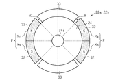
図1(a)に示すように、本実施形態のモータ10は、ブラシレスモータとして構成され、円環状のステータ11の内側にロータ21が配置されて構成されている。
ステータ11は、ステータコア12と、該ステータコア12に巻装された巻線13とを備えている。ステータコア12は、磁性金属にて略円環状に形成され、その周方向の等角度間隔においてそれぞれ径方向内側に延びる12個のティース12aを有している。
図2(a),(b)に示すように、ロータ21は、一対のロータ部(第1ロータ部22a及び第2ロータ部22b)が軸方向に積層されてなる。各ロータ部22a,22bは、互いに同一形状、同一構成をなし、周方向位置が互いにずれるように積層される。
具体的には、ロータ部22aは、永久磁石23をそれぞれ有するN極の磁石磁極MnとS極の磁石磁極Msとを備えている。各磁石磁極Mn,Msの永久磁石23は、磁気配向が径方向を向くように形成されている。より詳しくは、N極の磁石磁極Mnが備える永久磁石23は外周側にN極に現れるように磁化され、S極の磁石磁極Msが備える永久磁石23は外周側にS極に現れるように磁化されている。
図示しない駆動回路からそれぞれ120°の位相差を持つ3相の駆動電流(交流)がU相巻線U1〜U4、V相巻線V1〜V4及びW相巻線W1〜W4にそれぞれ供給されると、各巻線U1〜W4が相毎に同一タイミングで励磁されてステータ11に回転磁界が発生し、その回転磁界に基づいてロータ21が回転する。このとき、3相の駆動電流の供給によってステータ11側に形成される磁極は、各相の巻線U1〜W4毎で同極となる。なお、本実施形態のロータ21の磁極の数(磁石磁極Mn,Msの数)は4つであるが、各相の巻線U1〜W4には、ロータ21の極数(各ロータ部22a,22bの極数)を磁石磁極Mn,Msの数の2倍(本実施形態では8極)とみなして設定された駆動電流が供給される。
ここで、ロータの比較例として、例えばロータ部を1つのみを備えた構成(例えば上記第1ロータ部22aのみを備えた構成)では、磁束の強制力(誘導)のある磁石磁極Mn,Msと、磁束の強制力のない非磁極部26とが、ロータ周方向において混在することから、ロータに径方向に作用するラジアル力が周方向においてアンバランスとなり、そのことが振動の増大を招いてしまう。
(1)ステータ11の巻線13は、供給される3相の駆動電流に応じた、それぞれ4つのU相巻線U1〜U4、V相巻線V1〜V4及びW相巻線W1〜W4からなり、各相の4つの巻線はそれぞれ直列接続されている。つまり、ステータ11の巻線13は、各相において、直列接続された少なくとも2つの巻線(第1の巻線及び第2の巻線)を備える。
・上記実施形態では、各ロータ部22a,22b同士の周方向のずれ角θを90°に設定したが、これに特に限定されるものではなく、該ずれ角θを90°未満に設定してもよい。
・上記実施形態では、第1ロータ部22aと第2ロータ部22bとを軸方向に互いに当接するように積層したが、第1ロータ部22aと第2ロータ部22bとの軸方向間に非磁性層を介在させてもよい。例えば、図4(a),(b)に示す構成では、第1ロータ部22aと第2ロータ部22bとの軸方向間に、例えば樹脂材料よりなる非磁性部材31が非磁性層として介在されている。このような構成によれば、非磁性部材31によって各ロータ部22a,22b間での磁束の短絡を抑制でき、その結果、ロータ21の回転出力に寄与する有効磁束の低下を抑えることができる。
また、各ロータ部22a,22bにおける磁石磁極Mn,Ms及び突部33の配置は、図12に示す例に限定されるものではなく、磁石磁極Mn,Msの周方向反対側に突部33が位置する構成であれば、例えば、図13に示す構成のように変更してもよい。
・上記実施形態では、ロータ21をステータ11の内周側に配置したインナロータ型のモータ10に具体化したが、これに特に限定されるものではなく、ロータをステータの外周側に配置したアウタロータ型のモータに具体化してもよい。
Claims (7)
- ステータの巻線に駆動電流が供給されることで生じる回転磁界を受けてロータが回転するモータであって、
前記巻線は、前記駆動電流によって互いに同一のタイミングで励磁され、かつ、直列接続された第1の巻線と第2の巻線とを備え、
前記ロータは、永久磁石を有する磁石磁極と、前記磁石磁極が前記第1の巻線と対向するロータの回転位置で前記第2の巻線と対向し、該第2の巻線での弱め界磁電流による鎖交磁束の発生を許容する磁束許容部とをそれぞれ備えた複数のロータ部が軸方向に並設されてなり、
前記各ロータ部の前記磁石磁極の数は互いに同数であって、前記各ロータ部の前記磁石磁極の位置が周方向に互いにずれていることを特徴とするモータ。 - 請求項1に記載のモータにおいて、
前記各ロータ部において、周方向に隣接配置されたN極の前記磁石磁極とS極の前記磁石磁極とからなる磁極対が周方向等間隔に複数配置されていることを特徴とするモータ。 - 請求項2に記載のモータにおいて、
軸方向に並設される前記ロータ部の個数をm、前記各ロータ部の前記磁極対の個数をtとして、
前記各ロータ部は、軸方向一端のものから他端のものにかけて周方向一方に360/(m×t)(°)ずつずれていることを特徴とするモータ。 - ステータの巻線に駆動電流が供給されることで生じる回転磁界を受けてロータが回転するモータであって、
前記巻線は、前記駆動電流によって互いに同一のタイミングで励磁され、かつ、直列接続された第1の巻線と第2の巻線とを備え、
前記ロータは、複数のロータ部が軸方向に並設されてなり、
前記各ロータ部の磁極は、永久磁石を有する第1磁極部と、前記第1磁極部が前記第1の巻線と対向するロータの回転位置で前記第2の巻線と対向し、前記ステータ側に与える磁力が前記第1磁極部よりも弱い第2磁極部とを有し、
前記各ロータ部の磁極数は互いに同数であって、該各ロータ部の前記第1磁極部同士の磁極位置及び前記第2磁極部同士の磁極位置がそれぞれ周方向にずれていることを特徴とするモータ。 - 請求項4に記載のモータにおいて、
前記各ロータ部において、周方向に隣接配置されたN極の前記第1磁極部及びS極の前記第1磁極部からなる第1磁極対と、周方向に隣接配置されたN極の前記第2磁極部及びS極の前記第2磁極部からなる第2磁極対とが互いに同数設けられ、かつ、周方向等間隔に交互に配置されていることを特徴とするモータ。 - 請求項5に記載のモータにおいて、
軸方向に並設される前記ロータ部の個数をm、前記各ロータ部の前記第1磁極対の個数をtとして、
前記各ロータ部は、軸方向一端のものから他端のものにかけて周方向一方に360/(m×t)(°)ずつずれていることを特徴とするモータ。 - 請求項1〜6のいずれか1項に記載のモータにおいて、
前記各ロータ部の間に非磁性層が介在されていることを特徴とするモータ。
Priority Applications (5)
| Application Number | Priority Date | Filing Date | Title |
|---|---|---|---|
| JP2015251811A JP6589624B2 (ja) | 2015-12-24 | 2015-12-24 | モータ |
| US15/781,995 US10714992B2 (en) | 2015-12-24 | 2016-12-16 | Motor including plurality of rotor parts |
| PCT/JP2016/087621 WO2017110688A1 (ja) | 2015-12-24 | 2016-12-16 | モータ |
| CN201680069546.XA CN108432091B (zh) | 2015-12-24 | 2016-12-16 | 电动机 |
| DE112016006031.9T DE112016006031T5 (de) | 2015-12-24 | 2016-12-16 | Motor |
Applications Claiming Priority (1)
| Application Number | Priority Date | Filing Date | Title |
|---|---|---|---|
| JP2015251811A JP6589624B2 (ja) | 2015-12-24 | 2015-12-24 | モータ |
Publications (2)
| Publication Number | Publication Date |
|---|---|
| JP2017118691A JP2017118691A (ja) | 2017-06-29 |
| JP6589624B2 true JP6589624B2 (ja) | 2019-10-16 |
Family
ID=59090311
Family Applications (1)
| Application Number | Title | Priority Date | Filing Date |
|---|---|---|---|
| JP2015251811A Active JP6589624B2 (ja) | 2015-12-24 | 2015-12-24 | モータ |
Country Status (5)
| Country | Link |
|---|---|
| US (1) | US10714992B2 (ja) |
| JP (1) | JP6589624B2 (ja) |
| CN (1) | CN108432091B (ja) |
| DE (1) | DE112016006031T5 (ja) |
| WO (1) | WO2017110688A1 (ja) |
Families Citing this family (8)
| Publication number | Priority date | Publication date | Assignee | Title |
|---|---|---|---|---|
| JP6589624B2 (ja) | 2015-12-24 | 2019-10-16 | 株式会社デンソー | モータ |
| CN110462983A (zh) * | 2017-03-31 | 2019-11-15 | 日本电产株式会社 | 转子、马达以及电动助力转向装置 |
| WO2020008979A1 (ja) * | 2018-07-02 | 2020-01-09 | 日本電産株式会社 | ロータおよびモータ |
| CA3134252A1 (en) * | 2019-03-19 | 2020-09-24 | Magna International Inc. | High performance electromagnetic machine and cooling system |
| CN110994839B (zh) * | 2019-12-16 | 2020-11-17 | 珠海格力电器股份有限公司 | 电机转子和交替极电机 |
| JP7335831B2 (ja) | 2020-02-05 | 2023-08-30 | 本田技研工業株式会社 | 回転電機のロータ及び円弧磁石製造方法 |
| JP2021136840A (ja) * | 2020-02-28 | 2021-09-13 | 日本電産株式会社 | モータ |
| CN112910123B (zh) * | 2021-01-28 | 2022-03-25 | 南京航空航天大学 | 转子磁极调制型感应混合励磁无刷电机及发电系统 |
Family Cites Families (23)
| Publication number | Priority date | Publication date | Assignee | Title |
|---|---|---|---|---|
| US4918831A (en) * | 1987-12-28 | 1990-04-24 | General Electric Company | Method of fabricating composite rotor laminations for use in reluctance, homopolar and permanent magnet machines |
| JPH06351206A (ja) * | 1993-04-14 | 1994-12-22 | Meidensha Corp | ハイブリッド励磁形永久磁石同期回転機 |
| WO1997018616A1 (fr) * | 1995-11-16 | 1997-05-22 | Matsushita Electric Industrial Co., Ltd. | Moteur |
| JP3493865B2 (ja) * | 1995-12-27 | 2004-02-03 | アイシン・エィ・ダブリュ株式会社 | モータ |
| JP2000134891A (ja) * | 1998-10-28 | 2000-05-12 | Okuma Corp | 同期電動機およびその制御装置 |
| FR2787646B1 (fr) | 1998-12-18 | 2001-03-09 | Valeo Equip Electr Moteur | Machine electrique tournante a aimants permanents et a reluctance possedant une construction perfectionnee |
| US6486581B2 (en) * | 2000-03-31 | 2002-11-26 | Sanyo Denki Co., Ltd. | Interior permanent magnet synchronous motor |
| JP2002209349A (ja) | 2001-01-11 | 2002-07-26 | Toshiba Corp | 永久磁石式回転電機の回転子 |
| JP2006025572A (ja) * | 2004-07-09 | 2006-01-26 | Asmo Co Ltd | 埋込磁石型モータ |
| JP4635829B2 (ja) * | 2005-11-07 | 2011-02-23 | 三菱電機株式会社 | 永久磁石式電動機 |
| CN102170212B (zh) * | 2006-08-23 | 2012-07-18 | 株式会社东芝 | 永久磁铁式旋转电机 |
| US7652404B2 (en) * | 2007-05-31 | 2010-01-26 | General Electric Company | Synchronous reluctance machine |
| JP5329902B2 (ja) | 2008-10-10 | 2013-10-30 | アスモ株式会社 | 回転電機のロータ構造 |
| JP2011083066A (ja) | 2009-10-02 | 2011-04-21 | Osaka Prefecture Univ | 永久磁石補助形同期リラクタンスモータ |
| US20120001509A1 (en) | 2010-06-30 | 2012-01-05 | Asmo Co., Ltd. | Motor and rotor |
| JP2012034520A (ja) | 2010-07-30 | 2012-02-16 | Asmo Co Ltd | ロータ、及びモータ |
| US9806566B2 (en) | 2012-08-30 | 2017-10-31 | Asmo Co., Ltd. | Brushless motor, stator, stator manufacturing method and brushless motor manufacturing method |
| JP6084039B2 (ja) | 2013-01-10 | 2017-02-22 | アスモ株式会社 | ブラシレスモータ |
| JP2015095999A (ja) | 2013-11-13 | 2015-05-18 | 株式会社ジェイテクト | 回転電機 |
| DE102014208344A1 (de) * | 2014-05-05 | 2015-11-05 | Siemens Aktiengesellschaft | Rotorblechpaket |
| JP6062991B2 (ja) * | 2015-04-01 | 2017-01-18 | アスモ株式会社 | ロータ及びモータ |
| JP6589624B2 (ja) | 2015-12-24 | 2019-10-16 | 株式会社デンソー | モータ |
| KR20180115300A (ko) * | 2016-02-19 | 2018-10-22 | 무그 인코포레이티드 | 전기 모터의 로터 어셈블리 |
-
2015
- 2015-12-24 JP JP2015251811A patent/JP6589624B2/ja active Active
-
2016
- 2016-12-16 DE DE112016006031.9T patent/DE112016006031T5/de active Pending
- 2016-12-16 CN CN201680069546.XA patent/CN108432091B/zh active Active
- 2016-12-16 US US15/781,995 patent/US10714992B2/en active Active
- 2016-12-16 WO PCT/JP2016/087621 patent/WO2017110688A1/ja active Application Filing
Also Published As
| Publication number | Publication date |
|---|---|
| DE112016006031T5 (de) | 2018-09-13 |
| WO2017110688A1 (ja) | 2017-06-29 |
| US10714992B2 (en) | 2020-07-14 |
| CN108432091A (zh) | 2018-08-21 |
| CN108432091B (zh) | 2020-05-08 |
| US20180367000A1 (en) | 2018-12-20 |
| JP2017118691A (ja) | 2017-06-29 |
Similar Documents
| Publication | Publication Date | Title |
|---|---|---|
| JP6589624B2 (ja) | モータ | |
| CN107852051B (zh) | 电动机 | |
| CN107852050B (zh) | 电动机 | |
| JP5491484B2 (ja) | スイッチドリラクタンスモータ | |
| CN112838693B (zh) | 旋转电机 | |
| KR101952040B1 (ko) | 회전 전기 기기 | |
| JP2013074743A (ja) | 回転電機 | |
| TW201112583A (en) | Permanent magnet type synchronous motor | |
| JP7293371B2 (ja) | 回転電機の回転子 | |
| JP2018082600A (ja) | ダブルロータ型の回転電機 | |
| JP6657928B2 (ja) | モータ及びモータの磁束調整方法 | |
| WO2017171037A1 (ja) | ロータ及びロータの設計方法 | |
| WO2017014207A1 (ja) | モータ | |
| JP6711159B2 (ja) | モータ | |
| JP6607029B2 (ja) | モータ | |
| WO2018008475A1 (ja) | モータ | |
| WO2017014211A1 (ja) | モータ | |
| JP6631763B1 (ja) | 回転電機 | |
| JP2017216855A (ja) | 回転電機 | |
| JP6830073B2 (ja) | 回転電機 | |
| JP6481545B2 (ja) | モータ | |
| WO2018135405A1 (ja) | ロータ及びそれを用いたモータ | |
| JP5324025B2 (ja) | 回転電機 | |
| WO2018135409A1 (ja) | ロータ及びそれを用いたモータ | |
| JP6481546B2 (ja) | モータ |
Legal Events
| Date | Code | Title | Description |
|---|---|---|---|
| A711 | Notification of change in applicant |
Free format text: JAPANESE INTERMEDIATE CODE: A712 Effective date: 20180501 |
|
| A621 | Written request for application examination |
Free format text: JAPANESE INTERMEDIATE CODE: A621 Effective date: 20181015 |
|
| TRDD | Decision of grant or rejection written | ||
| A01 | Written decision to grant a patent or to grant a registration (utility model) |
Free format text: JAPANESE INTERMEDIATE CODE: A01 Effective date: 20190820 |
|
| A61 | First payment of annual fees (during grant procedure) |
Free format text: JAPANESE INTERMEDIATE CODE: A61 Effective date: 20190902 |
|
| R151 | Written notification of patent or utility model registration |
Ref document number: 6589624 Country of ref document: JP Free format text: JAPANESE INTERMEDIATE CODE: R151 |
|
| R250 | Receipt of annual fees |
Free format text: JAPANESE INTERMEDIATE CODE: R250 |
|
| R250 | Receipt of annual fees |
Free format text: JAPANESE INTERMEDIATE CODE: R250 |