JP6465415B2 - Exposure apparatus, flat panel display manufacturing method, device manufacturing method, and exposure method - Google Patents

Exposure apparatus, flat panel display manufacturing method, device manufacturing method, and exposure method Download PDF

Info

Publication number
JP6465415B2
JP6465415B2 JP2017011608A JP2017011608A JP6465415B2 JP 6465415 B2 JP6465415 B2 JP 6465415B2 JP 2017011608 A JP2017011608 A JP 2017011608A JP 2017011608 A JP2017011608 A JP 2017011608A JP 6465415 B2 JP6465415 B2 JP 6465415B2
Authority
JP
Japan
Prior art keywords
substrate
support
exposure
axis direction
exposure apparatus
Prior art date
Legal status (The legal status is an assumption and is not a legal conclusion. Google has not performed a legal analysis and makes no representation as to the accuracy of the status listed.)
Active
Application number
JP2017011608A
Other languages
Japanese (ja)
Other versions
JP2017085167A (en
Inventor
青木 保夫
保夫 青木
忠 関
忠 関
雅幸 長島
雅幸 長島
Current Assignee (The listed assignees may be inaccurate. Google has not performed a legal analysis and makes no representation or warranty as to the accuracy of the list.)
Nikon Corp
Original Assignee
Nikon Corp
Priority date (The priority date is an assumption and is not a legal conclusion. Google has not performed a legal analysis and makes no representation as to the accuracy of the date listed.)
Filing date
Publication date
Application filed by Nikon Corp filed Critical Nikon Corp
Publication of JP2017085167A publication Critical patent/JP2017085167A/en
Application granted granted Critical
Publication of JP6465415B2 publication Critical patent/JP6465415B2/en
Active legal-status Critical Current
Anticipated expiration legal-status Critical

Links

Images

Classifications

    • HELECTRICITY
    • H01ELECTRIC ELEMENTS
    • H01LSEMICONDUCTOR DEVICES NOT COVERED BY CLASS H10
    • H01L21/00Processes or apparatus adapted for the manufacture or treatment of semiconductor or solid state devices or of parts thereof
    • H01L21/67Apparatus specially adapted for handling semiconductor or electric solid state devices during manufacture or treatment thereof; Apparatus specially adapted for handling wafers during manufacture or treatment of semiconductor or electric solid state devices or components ; Apparatus not specifically provided for elsewhere
    • H01L21/67005Apparatus not specifically provided for elsewhere
    • H01L21/67011Apparatus for manufacture or treatment
    • H01L21/67155Apparatus for manufacturing or treating in a plurality of work-stations
    • H01L21/67161Apparatus for manufacturing or treating in a plurality of work-stations characterized by the layout of the process chambers
    • H01L21/67173Apparatus for manufacturing or treating in a plurality of work-stations characterized by the layout of the process chambers in-line arrangement
    • GPHYSICS
    • G03PHOTOGRAPHY; CINEMATOGRAPHY; ANALOGOUS TECHNIQUES USING WAVES OTHER THAN OPTICAL WAVES; ELECTROGRAPHY; HOLOGRAPHY
    • G03FPHOTOMECHANICAL PRODUCTION OF TEXTURED OR PATTERNED SURFACES, e.g. FOR PRINTING, FOR PROCESSING OF SEMICONDUCTOR DEVICES; MATERIALS THEREFOR; ORIGINALS THEREFOR; APPARATUS SPECIALLY ADAPTED THEREFOR
    • G03F7/00Photomechanical, e.g. photolithographic, production of textured or patterned surfaces, e.g. printing surfaces; Materials therefor, e.g. comprising photoresists; Apparatus specially adapted therefor
    • G03F7/70Microphotolithographic exposure; Apparatus therefor
    • G03F7/70691Handling of masks or workpieces
    • G03F7/70733Handling masks and workpieces, e.g. exchange of workpiece or mask, transport of workpiece or mask
    • G03F7/7075Handling workpieces outside exposure position, e.g. SMIF box
    • GPHYSICS
    • G03PHOTOGRAPHY; CINEMATOGRAPHY; ANALOGOUS TECHNIQUES USING WAVES OTHER THAN OPTICAL WAVES; ELECTROGRAPHY; HOLOGRAPHY
    • G03FPHOTOMECHANICAL PRODUCTION OF TEXTURED OR PATTERNED SURFACES, e.g. FOR PRINTING, FOR PROCESSING OF SEMICONDUCTOR DEVICES; MATERIALS THEREFOR; ORIGINALS THEREFOR; APPARATUS SPECIALLY ADAPTED THEREFOR
    • G03F7/00Photomechanical, e.g. photolithographic, production of textured or patterned surfaces, e.g. printing surfaces; Materials therefor, e.g. comprising photoresists; Apparatus specially adapted therefor
    • G03F7/70Microphotolithographic exposure; Apparatus therefor
    • G03F7/70691Handling of masks or workpieces
    • G03F7/70791Large workpieces, e.g. glass substrates for flat panel displays or solar panels
    • HELECTRICITY
    • H01ELECTRIC ELEMENTS
    • H01LSEMICONDUCTOR DEVICES NOT COVERED BY CLASS H10
    • H01L21/00Processes or apparatus adapted for the manufacture or treatment of semiconductor or solid state devices or of parts thereof
    • H01L21/67Apparatus specially adapted for handling semiconductor or electric solid state devices during manufacture or treatment thereof; Apparatus specially adapted for handling wafers during manufacture or treatment of semiconductor or electric solid state devices or components ; Apparatus not specifically provided for elsewhere
    • H01L21/677Apparatus specially adapted for handling semiconductor or electric solid state devices during manufacture or treatment thereof; Apparatus specially adapted for handling wafers during manufacture or treatment of semiconductor or electric solid state devices or components ; Apparatus not specifically provided for elsewhere for conveying, e.g. between different workstations
    • H01L21/67703Apparatus specially adapted for handling semiconductor or electric solid state devices during manufacture or treatment thereof; Apparatus specially adapted for handling wafers during manufacture or treatment of semiconductor or electric solid state devices or components ; Apparatus not specifically provided for elsewhere for conveying, e.g. between different workstations between different workstations
    • H01L21/67736Loading to or unloading from a conveyor
    • HELECTRICITY
    • H01ELECTRIC ELEMENTS
    • H01LSEMICONDUCTOR DEVICES NOT COVERED BY CLASS H10
    • H01L21/00Processes or apparatus adapted for the manufacture or treatment of semiconductor or solid state devices or of parts thereof
    • H01L21/67Apparatus specially adapted for handling semiconductor or electric solid state devices during manufacture or treatment thereof; Apparatus specially adapted for handling wafers during manufacture or treatment of semiconductor or electric solid state devices or components ; Apparatus not specifically provided for elsewhere
    • H01L21/677Apparatus specially adapted for handling semiconductor or electric solid state devices during manufacture or treatment thereof; Apparatus specially adapted for handling wafers during manufacture or treatment of semiconductor or electric solid state devices or components ; Apparatus not specifically provided for elsewhere for conveying, e.g. between different workstations
    • H01L21/67739Apparatus specially adapted for handling semiconductor or electric solid state devices during manufacture or treatment thereof; Apparatus specially adapted for handling wafers during manufacture or treatment of semiconductor or electric solid state devices or components ; Apparatus not specifically provided for elsewhere for conveying, e.g. between different workstations into and out of processing chamber
    • H01L21/67748Apparatus specially adapted for handling semiconductor or electric solid state devices during manufacture or treatment thereof; Apparatus specially adapted for handling wafers during manufacture or treatment of semiconductor or electric solid state devices or components ; Apparatus not specifically provided for elsewhere for conveying, e.g. between different workstations into and out of processing chamber horizontal transfer of a single workpiece
    • HELECTRICITY
    • H01ELECTRIC ELEMENTS
    • H01LSEMICONDUCTOR DEVICES NOT COVERED BY CLASS H10
    • H01L21/00Processes or apparatus adapted for the manufacture or treatment of semiconductor or solid state devices or of parts thereof
    • H01L21/67Apparatus specially adapted for handling semiconductor or electric solid state devices during manufacture or treatment thereof; Apparatus specially adapted for handling wafers during manufacture or treatment of semiconductor or electric solid state devices or components ; Apparatus not specifically provided for elsewhere
    • H01L21/677Apparatus specially adapted for handling semiconductor or electric solid state devices during manufacture or treatment thereof; Apparatus specially adapted for handling wafers during manufacture or treatment of semiconductor or electric solid state devices or components ; Apparatus not specifically provided for elsewhere for conveying, e.g. between different workstations
    • H01L21/67739Apparatus specially adapted for handling semiconductor or electric solid state devices during manufacture or treatment thereof; Apparatus specially adapted for handling wafers during manufacture or treatment of semiconductor or electric solid state devices or components ; Apparatus not specifically provided for elsewhere for conveying, e.g. between different workstations into and out of processing chamber
    • H01L21/67751Apparatus specially adapted for handling semiconductor or electric solid state devices during manufacture or treatment thereof; Apparatus specially adapted for handling wafers during manufacture or treatment of semiconductor or electric solid state devices or components ; Apparatus not specifically provided for elsewhere for conveying, e.g. between different workstations into and out of processing chamber vertical transfer of a single workpiece
    • HELECTRICITY
    • H01ELECTRIC ELEMENTS
    • H01LSEMICONDUCTOR DEVICES NOT COVERED BY CLASS H10
    • H01L21/00Processes or apparatus adapted for the manufacture or treatment of semiconductor or solid state devices or of parts thereof
    • H01L21/67Apparatus specially adapted for handling semiconductor or electric solid state devices during manufacture or treatment thereof; Apparatus specially adapted for handling wafers during manufacture or treatment of semiconductor or electric solid state devices or components ; Apparatus not specifically provided for elsewhere
    • H01L21/683Apparatus specially adapted for handling semiconductor or electric solid state devices during manufacture or treatment thereof; Apparatus specially adapted for handling wafers during manufacture or treatment of semiconductor or electric solid state devices or components ; Apparatus not specifically provided for elsewhere for supporting or gripping
    • H01L21/6838Apparatus specially adapted for handling semiconductor or electric solid state devices during manufacture or treatment thereof; Apparatus specially adapted for handling wafers during manufacture or treatment of semiconductor or electric solid state devices or components ; Apparatus not specifically provided for elsewhere for supporting or gripping with gripping and holding devices using a vacuum; Bernoulli devices

Description

本発明は、光装置、フラットパネルディスプレイの製造方法、デバイス製造方法、及び露光方法に係り、更に詳しくは、搬送された物体を順次走査露光する露光装置及び方法、並びに前記露光装置又は前記露光方法を用いたフラットパネルディスプレイの製造方法及びデバイス製造方法に関する。 The present invention, EXPOSURE APPARATUS, manufacturing method, device manufacturing method of the flat panel display, and an exposure method and, more particularly, an exposure apparatus and method for sequentially scanning exposure the conveyed object, and the exposure apparatus or the exposure The present invention relates to a flat panel display manufacturing method and a device manufacturing method using the method.

従来、液晶表示素子、半導体素子(集積回路等)等の電子デバイス(マイクロデバイス)を製造するリソグラフィ工程では、ステップ・アンド・リピート方式の投影露光装置(いわゆるステッパ)、あるいはステップ・アンド・スキャン方式の投影露光装置(いわゆるスキャニング・ステッパ(スキャナとも呼ばれる))などが用いられている。   Conventionally, in a lithography process for manufacturing electronic devices (microdevices) such as liquid crystal display elements and semiconductor elements (integrated circuits, etc.), a step-and-repeat projection exposure apparatus (so-called stepper) or step-and-scan method Projection exposure apparatuses (so-called scanning steppers (also called scanners)) are used.

この種の露光装置としては、基板の撓みを抑制するために、基板を下方から支持する基板支持部材を用いて基板ステージ装置に対して搬入するものが知られている(例えば、特許文献1参照)。   As this type of exposure apparatus, an apparatus that carries in a substrate stage apparatus using a substrate support member that supports the substrate from below in order to suppress the bending of the substrate is known (for example, see Patent Document 1). ).

ここで、近年の基板の大型化に伴い、基板を下方から支持するための上記基板支持部材も大型化している。しかし、基板支持部材は、基板を基板ステージに搬入した後、該基板の搬出時のために基板ステージに保持されるので、基板支持部材の大型化は、基板ステージの運動性能を低下させる可能性がある。   Here, with the recent increase in size of the substrate, the substrate support member for supporting the substrate from below is also increased in size. However, since the substrate support member is held by the substrate stage after the substrate is loaded onto the substrate stage, the increase in the size of the substrate support member may reduce the motion performance of the substrate stage. There is.

露光装置としては、搬入装置及び搬出装置を用いて基板ステージ上のガラス基板を適宜交換することにより、複数のガラス基板に対して連続して露光処理を行うものも知られている(例えば、特許文献2参照)。   As an exposure apparatus, there is also known an apparatus that performs exposure processing on a plurality of glass substrates continuously by appropriately replacing the glass substrate on the substrate stage using a carry-in device and a carry-out device (for example, patents). Reference 2).

ここで、複数のガラス基板に対して連続して露光を行う場合には、全体的なスループットの向上のためにもガラス基板を迅速に搬送することが好ましい。これに対し、近年、ガラス基板は、より大型化且つ薄型化される傾向にあり、その取り扱いには細心の注意が必要になっている。   Here, in the case where exposure is continuously performed on a plurality of glass substrates, it is preferable to rapidly convey the glass substrates in order to improve the overall throughput. On the other hand, in recent years, glass substrates tend to be larger and thinner, and careful handling is required for their handling.

米国特許第6,559,928号明細書US Pat. No. 6,559,928 米国特許出願公開第2011/0141448号明細書US Patent Application Publication No. 2011/0141448

本発明の第1の態様によれば、搬送された物体を順次走査露光する露光装置において、前記走査露光において前記物体を支持する支持面に設けられ、前記支持面に支持された前記物体に対して空気を供給する供給孔を有し、前記空気により前記支持面に対して前記物体を浮上支持可能な支持装置と、複数の前記物体のうち前記支持装置に浮上支持された第1物体を搬出する搬出装置と、前記第1物体が搬出された前記支持面に、前記第1物体とは異なる第2物体を搬入する搬入装置と、を備え、前記搬入装置は、前記第2物体を非接触支持する支持部と、前記第1物体を支持する前記支持装置の上方へ前記第2物体を非接触支持する前記支持部を駆動する駆動系と、前記支持部に支持された前記第2物体を下方から支持した状態で、前記支持部に対して下方へ相対移動させ、前記搬出装置により前記第1物体が搬出された前記支持面へ前記第2物体を搬入する搬入系と、を有し、前記支持と前記搬入系とは、前記第2物体を支持した状態で、前記第物体が搬出された前記支持に対して前記支持面に前記第2物体支持されるように下方へ相対移動する露光装置が、提供される。 According to the first aspect of the present invention, in an exposure apparatus that sequentially scans and exposes a conveyed object, the exposure apparatus is provided on a support surface that supports the object in the scanning exposure, and the object supported on the support surface A supply device for supplying air and supporting the object by floating with respect to the support surface by the air, and carrying out a first object floatingly supported by the support device among the plurality of objects. An unloading device, and an unloading device for unloading the second object different from the first object onto the support surface from which the first object is unloaded, the unloading device contacting the second object in a non-contact manner. a support for supporting, with the support portion driving system for driving the in a non-contact support the upward second object of the support apparatus for supporting the first object, a supported second object to said support portion while it supported from below, the support Is relatively moved downward with respect to, anda loading system for loading the second object to the said support surface first object is carried out by the unloading apparatus, wherein the support portion and the carrying system, wherein in a second state of the object to the support was, in pairs on the supporting surface of the first object is unloaded, the exposure and the second object on the support surface are relatively moved downward to be supported device, provided Is done.

本発明の第の態様によれば、上記第の態様に係る露光装置を用いて前記物体を露光することと、露光された前記物体を現像することと、を含むフラットパネルディスプレイの製造方法が、提供される。 According to a second aspect of the present invention, there is provided a method of manufacturing a flat panel display, comprising: exposing the object using the exposure apparatus according to the first aspect; and developing the exposed object. Is provided.

本発明の第の態様によれば、上記第の態様に係る露光装置を用いて前記物体を露光することと、露光された前記物体を現像することと、を含むデバイス製造方法が、提供される。 According to a third aspect of the present invention, there is provided a device manufacturing method comprising: exposing the object using the exposure apparatus according to the first aspect; and developing the exposed object. Is done.

本発明の第4の態様によれば、支持装置に搬送された物体を順次走査露光する露光方法であって、前記走査露光において前記物体を支持する支持面に設けられ、前記支持面に支持された前記物体に対して空気を供給する供給孔を有し、前記空気により前記支持面に対して前記物体を浮上支持させることと、複数の前記物体のうち、前記浮上支持された第1物体を搬出することと、前記支持面上に前記第1物体とは異なる第2物体を搬入することと、を含み、前記搬入することでは、前記第2物体の上方に配置された支持部を用いて、前記第2物体を非接触支持することと、前記支持部に支持された前記第2物体を、搬入装置を用いて、下方から支持することと、前記第1物体を支持する前記支持装置の上方へ第2物体を支持する前記支持部を駆動することと、前記第1物体が前記支持面上から搬出されると、前記支持部と前記搬入装置を用いて、前記第2物体を前記支持面に対して下方へ相対移動させ、前記支持部と前記搬入装置とで支持された状態から前記支持面上に搬入することと、を含む露光方法が、提供される。 According to a fourth aspect of the present invention, there is provided an exposure method for sequentially scanning and exposing an object conveyed to a support device, the exposure method being provided on a support surface that supports the object in the scanning exposure, and supported by the support surface. A supply hole for supplying air to the object, the object being levitated and supported with respect to the support surface by the air, and the first object that is levitated and supported among the plurality of objects. Carrying out, and carrying in a second object different from the first object onto the support surface, and using the support portion disposed above the second object , Supporting the second object in a non-contact manner, supporting the second object supported by the support portion from below using a loading device, and supporting the first object. The support part for supporting the second object upward; The method comprising moving, when the first object is unloaded from the said support surface, with said loading device and the support portion, is relatively moved downward with the second object with respect to the support surface, the exposure method from the support state with the support portion and the loading device including a method comprising carrying on the support surface is provided.

本発明の第の態様によれば、上記第の態様に係る露光方法を用いて前記物体を露光することと、露光された前記物体を現像することと、を含むフラットパネルディスプレイの製造方法が、提供される。 According to a fifth aspect of the present invention, there is provided a flat panel display manufacturing method comprising: exposing the object using the exposure method according to the fourth aspect; and developing the exposed object. Is provided.

本発明の第の態様によれば、上記第の態様にかかる露光方法を用いて前記物体を露光することと、露光された前記物体を現像することと、を含むデバイス製造方法が、提供される。 According to a sixth aspect of the present invention, there is provided a device manufacturing method comprising: exposing the object using the exposure method according to the fourth aspect; and developing the exposed object. Is done.

第1の実施形態に係る液晶露光装置の構成を概略的に示す図である。It is a figure which shows schematically the structure of the liquid-crystal exposure apparatus which concerns on 1st Embodiment. 図1の液晶露光装置が有する基板ステージ装置、ポート部、及び基板搬入装置の側面図である。FIG. 2 is a side view of a substrate stage device, a port unit, and a substrate carry-in device that the liquid crystal exposure apparatus of FIG. 1 has. 図2の基板ステージ装置が有する基板ホルダの平面図である。It is a top view of the substrate holder which the substrate stage apparatus of FIG. 2 has. 図2のポート部、及び基板搬入装置の平面図である。It is a top view of the port part of FIG. 2, and a board | substrate carrying-in apparatus. 図5(A)及び図5(B)は、基板の交換動作を説明するための図(その1及びその2)である。FIGS. 5A and 5B are views (No. 1 and No. 2) for explaining the substrate replacement operation. 図6(A)及び図6(B)は、基板の交換動作を説明するための図(その3及びその4)である。FIGS. 6A and 6B are views (No. 3 and No. 4) for explaining the substrate replacement operation. 図7(A)及び図7(B)は、基板の交換動作を説明するための図(その5及びその6)である。FIGS. 7A and 7B are views (No. 5 and No. 6) for explaining the substrate replacement operation. 図8(A)及び図8(B)は、基板の交換動作を説明するための図(その7及びその8)である。FIGS. 8A and 8B are views (No. 7 and No. 8) for explaining the substrate replacement operation. 図9(A)及び図9(B)は、基板の交換動作を説明するための図(その9及びその10)である。FIGS. 9A and 9B are views (No. 9 and No. 10) for explaining the substrate replacement operation. 図10(A)及び図10(B)は、基板の交換動作を説明するための図(その11及びその12)である。FIGS. 10A and 10B are views (Nos. 11 and 12) for explaining the substrate replacement operation. 図11(A)〜図11(C)は、基板搬出装置の動作を説明するための図(その1〜その3)である。FIGS. 11A to 11C are views (No. 1 to No. 3) for explaining the operation of the substrate carry-out apparatus. 図12(A)及び図12(B)は、基板搬入装置の動作を説明するための図(その1及びその2)である。12A and 12B are views (No. 1 and No. 2) for explaining the operation of the substrate carry-in apparatus. 図13(A)は、第2の実施形態に係る基板ステージの断面図、図13(B)は、図13(A)の基板ステージが有する基板ホルダの平面図である。FIG. 13A is a cross-sectional view of a substrate stage according to the second embodiment, and FIG. 13B is a plan view of a substrate holder included in the substrate stage of FIG. 図14(A)〜図14(C)は、図13(A)の基板ステージ120が有する基板搬出装置170の動作を説明するための図(その1〜その3)である。14A to 14C are views (No. 1 to No. 3) for explaining the operation of the substrate carry-out device 170 included in the substrate stage 120 of FIG. 13A. 図15(A)及び図15(B)は、第2の実施形態における基板の交換動作を説明するための図(その1及びその2)である。FIGS. 15A and 15B are views (No. 1 and No. 2) for explaining the substrate replacement operation in the second embodiment. 図16(A)及び図16(B)は、第2の実施形態における基板の交換動作を説明するための図(その3及びその4)である。FIGS. 16A and 16B are views (No. 3 and No. 4) for explaining the substrate replacement operation in the second embodiment. 図17(A)及び図17(B)は、第2の実施形態における基板の交換動作を説明するための図(その5及びその6)である。FIGS. 17A and 17B are views (No. 5 and No. 6) for explaining the substrate replacement operation in the second embodiment. 図18(A)及び図18(B)は、第2の実施形態における基板の交換動作を説明するための図(その7及びその8)である。FIGS. 18A and 18B are views (No. 7 and No. 8) for explaining the substrate replacement operation in the second embodiment. 図19(A)及び図19(B)は、第2の実施形態における基板の交換動作を説明するための図(その9及びその10)である。FIGS. 19A and 19B are views (No. 9 and No. 10) for explaining the substrate replacement operation in the second embodiment. 図20(A)及び図20(B)は、第2の実施形態における基板の交換動作を説明するための図(その11及びその12)である。FIGS. 20A and 20B are views (No. 11 and No. 12) for explaining the substrate replacement operation in the second embodiment. 図21(A)及び図21(B)は、第2の実施形態における基板の交換動作を説明するための図(その13及びその14)である。FIGS. 21A and 21B are views (No. 13 and No. 14) for explaining the substrate replacement operation in the second embodiment. 図22(A)及び図22(B)は、第2の実施形態における基板の交換動作を説明するための図(その15及びその16)である。FIGS. 22A and 22B are views (No. 15 and No. 16) for explaining the substrate replacement operation in the second embodiment. 第1の変形例に係る基板搬入装置の平面図である。It is a top view of the board | substrate carrying-in apparatus which concerns on a 1st modification. 第2の変形例に係る基板搬入装置の平面図である。It is a top view of the board | substrate carrying-in apparatus which concerns on a 2nd modification. 第3の変形例に係る基板ホルダの平面図である。It is a top view of the substrate holder concerning the 3rd modification. 図26(A)及び図26(B)は、第4の変形例に係る基板搬入装置の動作を説明するための図(その1及びその2)である。FIGS. 26A and 26B are views (No. 1 and No. 2) for explaining the operation of the substrate carry-in apparatus according to the fourth modification. 図27(A)及び図27(B)は、第4の変形例に係る基板搬入装置の動作を説明するための図(その3及びその4)である。FIGS. 27A and 27B are views (No. 3 and No. 4) for explaining the operation of the substrate carrying-in apparatus according to the fourth modified example. 第3の実施形態に係る液晶露光装置の構成を概略的に示す図である。It is a figure which shows schematically the structure of the liquid-crystal exposure apparatus which concerns on 3rd Embodiment. 図28の液晶露光装置が有する基板ステージ、及びポート部の断面図である。It is sectional drawing of the substrate stage and port part which the liquid-crystal exposure apparatus of FIG. 28 has. 図29のポート部の平面図(その1)である。FIG. 30 is a plan view (part 1) of the port portion of FIG. 29; 図29のポート部の平面図(その2)である。FIG. 30 is a plan view (No. 2) of the port portion of FIG. 29. 基板ガイド装置及び基板搬入装置を示す図である。It is a figure which shows a board | substrate guide apparatus and a board | substrate carrying-in apparatus. 図33(A)及び図33(B)は、基板搬入動作を説明するための図(その1及びその2)である。FIGS. 33A and 33B are views (No. 1 and No. 2) for explaining the substrate carrying-in operation. 図34(A)及び図34(B)は、基板交換動作を説明するための図(その1及びその2)である。FIGS. 34A and 34B are views (No. 1 and No. 2) for explaining the substrate replacement operation. 図35(A)及び図35(B)は、基板交換動作を説明するための図(その3及びその4)である。FIGS. 35A and 35B are views (No. 3 and No. 4) for explaining the substrate replacement operation. 図36(A)及び図36(B)は、基板交換動作を説明するための図(その5及びその6)である。FIGS. 36A and 36B are views (No. 5 and No. 6) for explaining the substrate replacement operation. 図37(A)及び図37(B)は、基板交換動作を説明するための図(その7及びその8)である。FIGS. 37A and 37B are views (No. 7 and No. 8) for explaining the substrate replacement operation. 図38(A)及び図38(B)は、基板交換動作を説明するための図(その9及びその10)である。FIGS. 38A and 38B are views (No. 9 and No. 10) for explaining the substrate replacement operation. 図39(A)及び図39(B)は、基板交換動作を説明するための図(その11及びその12)である。FIG. 39A and FIG. 39B are views (No. 11 and No. 12) for explaining the substrate replacement operation. 第4の実施形態に係る基板搬入装置を示す図である。It is a figure which shows the board | substrate carrying-in apparatus which concerns on 4th Embodiment. 図41(A)〜図41(C)は、第4の実施形態における基板搬入動作を説明するための図(その1〜その3)である。FIGS. 41A to 41C are views (No. 1 to No. 3) for explaining the substrate carry-in operation in the fourth embodiment. 図42(A)及び図42(B)は、第4の実施形態の変形例(その1)を説明するための図である。FIG. 42A and FIG. 42B are diagrams for describing a modification example (No. 1) of the fourth embodiment. 図43(A)及び図43(B)は、第4の実施形態の変形例(その2)を説明するための図である。FIG. 43A and FIG. 43B are diagrams for explaining a modification (No. 2) of the fourth embodiment. 第5の実施形態に係る基板ステージを示す図である。It is a figure which shows the substrate stage which concerns on 5th Embodiment. 第5の実施形態に係る基板ステージの断面図である。It is sectional drawing of the substrate stage which concerns on 5th Embodiment. 第5の実施形態における基板搬入動作を説明するための図である。It is a figure for demonstrating board | substrate carrying-in operation | movement in 5th Embodiment.

《第1の実施形態》
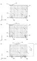
以下、第1の実施形態について、図1〜図12(B)に基づいて説明する。
<< First Embodiment >>
Hereinafter, the first embodiment will be described with reference to FIGS. 1 to 12B.

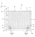
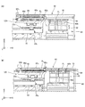
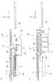
図1には、第1の実施形態に係る液晶露光装置10の構成が概略的に示されている。液晶露光装置10は、例えば液晶表示装置(フラットパネルディスプレイ)などに用いられる矩形(角型)のガラス基板P(図1では基板P及び基板P。以下、適宜まとめて基板Pと称する)を露光対象物とする投影露光装置である。 FIG. 1 schematically shows the configuration of a liquid crystal exposure apparatus 10 according to the first embodiment. The liquid crystal exposure apparatus 10 is a rectangular (square) glass substrate P used in, for example, a liquid crystal display device (flat panel display) (substrate P 1 and substrate P 2 in FIG. 1; hereinafter, collectively referred to as substrate P). Is a projection exposure apparatus that uses as an exposure object.

液晶露光装置10は、照明系IOP、マスクMを保持するマスクステージMST、投影光学系PL、装置本体30、表面(図1で+Z側を向いた面)にレジスト(感応剤)が塗布された基板P(図1では基板P)を保持する基板ステージ装置PST、外部装置(例えば、コータ・デベロッパ装置)との間で基板Pの受け渡しを行うポート部60(図1では不図示。図2参照)、基板ステージ装置PSTに基板P(図1では基板P)を搬入する基板搬入装置80、及びこれらの制御系等を有している。以下、露光時にマスクMと基板Pとが投影光学系PLに対してそれぞれ相対走査される方向をX軸方向とし、水平面内でX軸に直交する方向をY軸方向、X軸及びY軸に直交する方向をZ軸方向とし、X軸、Y軸、及びZ軸回りの回転方向をそれぞれθx、θy、及びθz方向として説明を行う。また、X軸、Y軸、及びZ軸方向に関する位置をそれぞれX位置、Y位置、及びZ位置として説明を行う。 In the liquid crystal exposure apparatus 10, a resist (sensitive agent) is applied to the illumination system IOP, the mask stage MST that holds the mask M, the projection optical system PL, the apparatus main body 30, and the surface (the surface facing the + Z side in FIG. 1). A port unit 60 (not shown in FIG. 1; not shown in FIG. 1) that transfers the substrate P between the substrate stage device PST that holds the substrate P (substrate P 1 in FIG. 1) and an external device (for example, a coater / developer device). (See FIG. 1), a substrate carry-in device 80 for carrying the substrate P (substrate P 2 in FIG. 1) into the substrate stage device PST, and a control system thereof. Hereinafter, the direction in which the mask M and the substrate P are relatively scanned with respect to the projection optical system PL at the time of exposure is defined as the X-axis direction, and the direction orthogonal to the X-axis in the horizontal plane is defined as the Y-axis direction, X-axis, and Y-axis. The description will be made assuming that the orthogonal direction is the Z-axis direction, and the rotation directions around the X-axis, Y-axis, and Z-axis are the θx, θy, and θz directions, respectively. Further, description will be made assuming that the positions in the X-axis, Y-axis, and Z-axis directions are the X position, the Y position, and the Z position, respectively.

照明系IOPは、例えば米国特許第6,552,775号明細書などに開示される照明系と同様に構成されている。すなわち、照明系IOPは、図示しない光源(例えば、水銀ランプ)から射出された光を、それぞれ図示しない反射鏡、ダイクロイックミラー、シャッター、波長選択フィルタ、各種レンズなどを介して、露光用照明光(照明光)ILとしてマスクMに照射する。照明光ILとしては、例えばi線(波長365nm)、g線(波長436nm)、h線(波長405nm)などの光(あるいは、上記i線、g線、h線の合成光)が用いられる。   The illumination system IOP is configured similarly to the illumination system disclosed in, for example, US Pat. No. 6,552,775. That is, the illumination system IOP emits light emitted from a light source (not shown) (for example, a mercury lamp) through exposure mirrors (not shown), dichroic mirrors, shutters, wavelength selection filters, various lenses, and the like. Irradiation light) is applied to the mask M as IL. As the illumination light IL, for example, light such as i-line (wavelength 365 nm), g-line (wavelength 436 nm), h-line (wavelength 405 nm), or the combined light of the i-line, g-line, and h-line is used.

マスクステージMSTには、回路パターンなどがそのパターン面に形成されたマスクMが、例えば真空吸着により吸着保持されている。マスクステージMSTは、装置本体30(ボディ)の一部である鏡筒定盤31上に搭載され、例えばリニアモータを含むマスクステージ駆動系(不図示)により走査方向(X軸方向)に所定の長ストロークで駆動されるとともに、Y軸方向、及びθz方向に適宜微少駆動される。マスクステージMSTのXY平面内の位置情報(θz方向の回転情報を含む)は、不図示のレーザ干渉計を含むマスク干渉計システムにより計測される。   On the mask stage MST, a mask M on which a circuit pattern or the like is formed is held by suction, for example, by vacuum suction. The mask stage MST is mounted on a lens barrel base plate 31 that is a part of the apparatus main body 30 (body), and is predetermined in the scanning direction (X-axis direction) by a mask stage drive system (not shown) including, for example, a linear motor. While being driven by a long stroke, it is slightly driven as appropriate in the Y-axis direction and the θz direction. Position information (including rotation information in the θz direction) of the mask stage MST in the XY plane is measured by a mask interferometer system including a laser interferometer (not shown).

投影光学系PLは、マスクステージMSTの下方に配置され、装置本体30の一部である鏡筒定盤31に支持されている。投影光学系PLは、例えば米国特許第6,552,775号明細書に開示された投影光学系と同様に構成されている。すなわち、投影光学系PLは、マスクMのパターン像の投影領域が千鳥状に配置された複数の投影光学系(マルチレンズ投影光学系)を含み、Y軸方向を長手方向とする長方形状の単一のイメージフィールドを持つ投影光学系と同等に機能する。本実施形態では、複数の投影光学系それぞれとしては、例えば両側テレセントリックな等倍系で正立正像を形成するものが用いられている。   The projection optical system PL is disposed below the mask stage MST and supported by a lens barrel base plate 31 that is a part of the apparatus main body 30. The projection optical system PL is configured similarly to the projection optical system disclosed in, for example, US Pat. No. 6,552,775. In other words, the projection optical system PL includes a plurality of projection optical systems (multi-lens projection optical systems) in which the projection areas of the pattern image of the mask M are arranged in a staggered pattern, and is a rectangular single unit whose longitudinal direction is the Y-axis direction. Functions in the same way as a projection optical system having one image field. In the present embodiment, as each of the plurality of projection optical systems, for example, a bilateral telecentric equal magnification system that forms an erect image is used.

このため、照明系IOPからの照明光ILによってマスクM上の照明領域が照明されると、マスクMを通過した照明光ILにより、投影光学系PLを介してその照明領域内のマスクMの回路パターンの投影像(部分正立像)が、基板P上の照明領域に共役な照明光ILの照射領域(露光領域)に形成される。そして、マスクステージMSTと基板ステージ装置PSTとの同期駆動によって、照明領域(照明光IL)に対してマスクMを走査方向に相対移動させるとともに、露光領域(照明光IL)に対して基板Pを走査方向に相対移動させることで、基板P上の1つのショット領域の走査露光が行われ、そのショット領域にマスクMに形成されたパターンが転写される。すなわち、本実施形態では照明系IOP及び投影光学系PLによって基板P上にマスクMのパターンが生成され、照明光ILによる基板P上の感応層(レジスト層)の露光によって基板P上にそのパターンが形成される。   For this reason, when the illumination area on the mask M is illuminated by the illumination light IL from the illumination system IOP, the illumination light IL that has passed through the mask M causes the circuit of the mask M in the illumination area to pass through the projection optical system PL. A projected image (partial upright image) of the pattern is formed in the irradiation region (exposure region) of the illumination light IL conjugate to the illumination region on the substrate P. Then, by synchronous driving of the mask stage MST and the substrate stage apparatus PST, the mask M is moved relative to the illumination area (illumination light IL) in the scanning direction, and the substrate P is moved relative to the exposure area (illumination light IL). By performing relative movement in the scanning direction, scanning exposure of one shot area on the substrate P is performed, and the pattern formed on the mask M is transferred to the shot area. That is, in this embodiment, the pattern of the mask M is generated on the substrate P by the illumination system IOP and the projection optical system PL, and the pattern is formed on the substrate P by exposure of the sensitive layer (resist layer) on the substrate P by the illumination light IL. Is formed.

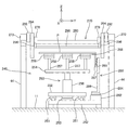
装置本体30は、鏡筒定盤31、一対のサイドコラム32、及び基板ステージ架台33を有している。鏡筒定盤31は、XY平面に平行に配置された板状の部材から成り、上記投影光学系PL、マスクステージMSTなどを支持している。一対のサイドコラム32は、一方が鏡筒定盤31の+Y側の端部近傍を、他方が鏡筒定盤31の−Y側の端部近傍を、それぞれ下方から支持している。基板ステージ架台33は、Y軸方向に延びる部材から成り、クリーンルームの床11上に設置された防振装置34により下方から支持されている。上記一対のサイドコラム32は、一方が基板ステージ架台33の+Y側の端部近傍上に搭載され、他方が基板ステージ架台33の−Y側の端部近傍上にそれぞれ搭載されている。鏡筒定盤31、一対のサイドコラム32、及び基板ステージ架台33は、一体的に連結されている。これにより、装置本体30(及び投影光学系PL、マスクステージMSTなど)が、床11から振動的に分離される。   The apparatus main body 30 includes a lens barrel base plate 31, a pair of side columns 32, and a substrate stage mount 33. The lens barrel surface plate 31 is composed of a plate-like member arranged in parallel with the XY plane, and supports the projection optical system PL, the mask stage MST, and the like. One of the pair of side columns 32 supports the vicinity of the + Y side end of the lens barrel base plate 31 and the other supports the vicinity of the −Y side end of the lens barrel base plate 31 from below. The substrate stage mount 33 is made of a member extending in the Y-axis direction, and is supported from below by a vibration isolator 34 installed on the floor 11 of the clean room. One of the pair of side columns 32 is mounted on the vicinity of the + Y side end of the substrate stage mount 33, and the other is mounted on the vicinity of the −Y side end of the substrate stage mount 33. The lens barrel base plate 31, the pair of side columns 32, and the substrate stage mount 33 are integrally connected. As a result, the apparatus main body 30 (and projection optical system PL, mask stage MST, etc.) is vibrationally separated from the floor 11.

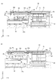
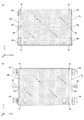
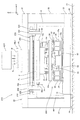
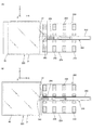
基板ステージ装置PSTは、図2に示されるように、ベースフレーム14、及び基板ステージ20を備えている。なお、図1に示される基板ステージ20は、図2のA−A線断面に相当し、図1に示される基板搬入装置80は、図2のB−B線断面に相当する。   The substrate stage apparatus PST includes a base frame 14 and a substrate stage 20 as shown in FIG. The substrate stage 20 shown in FIG. 1 corresponds to the cross section along line AA in FIG. 2, and the substrate carry-in device 80 shown in FIG. 1 corresponds to the cross section along line BB in FIG.

ベースフレーム14は、Y軸方向に延びる部材から成り、基板ステージ架台33に所定距離隔てて(非接触状態で)床11上に配置されている。ベースフレーム14は、後述する基板ステージ20の一部であるY粗動ステージ23yを下方から支持しており、基板ステージ20がY軸方向に所定の長ストロークで移動する際のガイド部材として機能する。ベースフレーム14は、X軸方向に離間して一対設けられ(図2では一方は不図示)、Y粗動ステージ23yの長手方向の両端部近傍を下方から支持している。なお、基板ステージ架台33がX軸方向に所定間隔で複数設けられる場合には、互いに隣接する基板ステージ架台33の間に、Y粗動ステージ23yの長手方向の中間部を支持する補助的なベースフレームを配置しても良い。ベースフレーム14の上端面(+Z側の端部)には、Yリニアガイド装置の要素であるYリニアガイド16aが固定されている。   The base frame 14 is made of a member extending in the Y-axis direction, and is arranged on the floor 11 at a predetermined distance from the substrate stage mount 33 (in a non-contact state). The base frame 14 supports a Y coarse movement stage 23y, which is a part of a substrate stage 20, which will be described later, from below, and functions as a guide member when the substrate stage 20 moves with a predetermined long stroke in the Y-axis direction. . A pair of base frames 14 are provided apart from each other in the X-axis direction (one is not shown in FIG. 2), and supports the vicinity of both ends in the longitudinal direction of the Y coarse movement stage 23y from below. When a plurality of substrate stage stands 33 are provided at predetermined intervals in the X-axis direction, an auxiliary base that supports an intermediate portion in the longitudinal direction of the Y coarse movement stage 23y between the substrate stage stands 33 adjacent to each other. A frame may be arranged. A Y linear guide 16a, which is an element of the Y linear guide device, is fixed to the upper end surface (+ Z side end) of the base frame 14.

基板ステージ20は、Y粗動ステージ23y、X粗動ステージ23x、微動ステージ21、基板ホルダ40、Yステップ定盤50、重量キャンセル装置54、及び基板搬出装置70を有している。   The substrate stage 20 includes a Y coarse movement stage 23y, an X coarse movement stage 23x, a fine movement stage 21, a substrate holder 40, a Y step surface plate 50, a weight cancellation device 54, and a substrate carry-out device 70.

Y粗動ステージ23yは、基板ステージ架台33の上方に配置され、ベースフレーム14上に搭載されている。Y粗動ステージ23yは、図1に示されるように、一対のXビーム25を有している。Xビーム25は、X軸方向に延びるYZ断面が矩形の部材から成る。一対のXビーム25は、−X側及び+X側(図1では不図示。図2参照)の端部近傍それぞれにおいて、Yキャリッジ26と称される板状の部材により一体的に接続されている。Yキャリッジ26の下面には、上記Yリニアガイド16aと共にYリニアガイド装置16を構成するYスライド部材16bが固定されている。Yスライド部材16bは、対応するYリニアガイド16aに低摩擦でスライド自在に係合しており、Y粗動ステージ23yは、一対のベースフレーム14上を低摩擦でY軸方向に所定のストロークで移動可能となっている。   The Y coarse movement stage 23 y is disposed above the substrate stage mount 33 and is mounted on the base frame 14. The Y coarse movement stage 23y has a pair of X beams 25 as shown in FIG. The X beam 25 is made of a member having a rectangular YZ section extending in the X-axis direction. The pair of X beams 25 are integrally connected by a plate-like member called a Y carriage 26 in the vicinity of the ends on the −X side and the + X side (not shown in FIG. 1; see FIG. 2). . A Y slide member 16b constituting the Y linear guide device 16 is fixed to the lower surface of the Y carriage 26 together with the Y linear guide 16a. The Y slide member 16b is slidably engaged with the corresponding Y linear guide 16a with low friction, and the Y coarse movement stage 23y has a predetermined stroke in the Y axis direction with low friction on the pair of base frames 14. It is movable.

Y粗動ステージ23yは、不図示のYアクチュエータにより、一対のベースフレーム14上でY軸方向に駆動される。Yアクチュエータの種類は、特に限定されないが、例えば送りねじ装置、リニアモータ、ベルト駆動装置などを用いることができる。一対のXビーム25それぞれの上面には、Xリニアガイド装置の要素であるXリニアガイド27aがY軸方向に所定間隔で、例えば2本固定されている。また、各Xビーム25の上面であって、例えば2本のXリニアガイド27a間の領域には、X軸方向に所定間隔で配列された複数の永久磁石を含む磁石ユニット28a(X固定子)が固定されている。   The Y coarse movement stage 23y is driven in the Y-axis direction on the pair of base frames 14 by a Y actuator (not shown). Although the kind of Y actuator is not specifically limited, For example, a feed screw device, a linear motor, a belt drive device, etc. can be used. For example, two X linear guides 27a, which are elements of the X linear guide device, are fixed on the upper surfaces of the pair of X beams 25 at predetermined intervals in the Y-axis direction. Further, a magnet unit 28a (X stator) including a plurality of permanent magnets arranged at predetermined intervals in the X-axis direction in the upper surface of each X beam 25, for example, in a region between two X linear guides 27a. Is fixed.

X粗動ステージ23xは、平面視矩形の板状部材から成り、その中央部に開口部(不図示)が形成されている。X粗動ステージ23xの下面には、上記各Xリニアガイド27aと共にXリニアガイド装置27を構成するXスライド部材27bがスペーサ29を介して固定されている。Xスライド部材27bは、一本のXリニアガイド27aにつき、X軸方向に所定間隔で、例えば4つ設けられている。Xスライド部材27bは、対応するXリニアガイド27aに低摩擦でスライド自在に係合しており、X粗動ステージ23xは、一対のXビーム25上を低摩擦でX軸方向に所定のストロークで移動可能となっている。また、X粗動ステージ23xの下面には、各磁石ユニット28aと共にX粗動ステージ23xをX軸方向に所定のストロークで駆動するためのXリニアモータ28を構成するコイルユニット28b(X可動子)が固定されている。   The X coarse movement stage 23x is made of a plate member having a rectangular shape in plan view, and an opening (not shown) is formed at the center thereof. An X slide member 27 b that constitutes the X linear guide device 27 together with the X linear guides 27 a is fixed to the lower surface of the X coarse movement stage 23 x via a spacer 29. For example, four X slide members 27b are provided at a predetermined interval in the X-axis direction for each X linear guide 27a. The X slide member 27b is slidably engaged with the corresponding X linear guide 27a with low friction, and the X coarse movement stage 23x has a predetermined stroke in the X-axis direction with low friction on the pair of X beams 25. It is movable. Further, on the lower surface of the X coarse movement stage 23x, a coil unit 28b (X mover) constituting an X linear motor 28 for driving the X coarse movement stage 23x with a predetermined stroke in the X axis direction together with each magnet unit 28a. Is fixed.

X粗動ステージ23xは、複数(図1では4つ)のXリニアガイド装置27によりY粗動ステージ23yに対するY軸方向への相対移動が制限されており、Y粗動ステージ23yと一体的にY軸方向に移動する。すなわち、X粗動ステージ23xは、Y粗動ステージ23yと共に、ガントリ式の2軸ステージ装置を構成している。Y粗動ステージ23yのY位置情報、及びX粗動ステージ23xのX位置情報それぞれは、例えば不図示のリニアエンコーダシステムにより求められる。   The X coarse movement stage 23x is restricted in relative movement in the Y-axis direction with respect to the Y coarse movement stage 23y by a plurality of (four in FIG. 1) X linear guide devices 27, and is integrated with the Y coarse movement stage 23y. Move in the Y-axis direction. That is, the X coarse movement stage 23x and the Y coarse movement stage 23y constitute a gantry-type two-axis stage device. The Y position information of the Y coarse movement stage 23y and the X position information of the X coarse movement stage 23x are obtained, for example, by a linear encoder system (not shown).

微動ステージ21は、平面視矩形の箱形部材から成り、その上面に基板ホルダ40が固定されている。微動ステージ21は、X粗動ステージ23xに固定された固定子と、微動ステージ21に固定された可動子とから成る複数のボイスコイルモータを含む微動ステージ駆動系により、X粗動ステージ23x上で3自由度方向(X軸、Y軸、θz方向)に微少駆動される。複数のボイスコイルモータには、X軸方向の推力を発生する複数のXボイスコイルモータ(図1では不図示)、及びY軸方向の推力を発生する複数のYボイスコイルモータ18yが含まれる(ただし図2では、図面の錯綜を避けるため複数のボイスコイルモータは、不図示)。   The fine movement stage 21 is made of a box-shaped member having a rectangular shape in plan view, and the substrate holder 40 is fixed on the upper surface thereof. The fine movement stage 21 is moved on the X coarse movement stage 23x by a fine movement stage drive system including a plurality of voice coil motors including a stator fixed to the X coarse movement stage 23x and a mover fixed to the fine movement stage 21. It is slightly driven in the direction of three degrees of freedom (X axis, Y axis, θz direction). The plurality of voice coil motors include a plurality of X voice coil motors (not shown in FIG. 1) that generate thrust in the X-axis direction, and a plurality of Y voice coil motors 18y that generate thrust in the Y-axis direction ( However, in FIG. 2, a plurality of voice coil motors are not shown in order to avoid confusion in the drawing).

微動ステージ21は、上記複数のボイスコイルモータが発生する推力によりX粗動ステージ23xに誘導されることにより、X粗動ステージ23xと共にX軸方向、及び/又はY軸方向に所定のストロークで移動する。また、微動ステージ21は、複数のボイスコイルモータによりX粗動ステージ23xに対して上記3自由度方向に適宜微少駆動される。また、微動ステージ駆動系は、微動ステージ21をθx、θy、及びZ軸方向の3自由度方向に微少駆動するための複数のZボイスコイルモータ18zを有している。複数のZボイスコイルモータは、例えば微動ステージ21の四隅部に対応する箇所に配置されている。複数のボイスコイルモータを含み、微動ステージ駆動系の構成については、例えば米国特許出願公開第2010/0018950号明細書に開示されている。   The fine movement stage 21 is guided to the X coarse movement stage 23x by the thrust generated by the plurality of voice coil motors, and moves with the X coarse movement stage 23x with a predetermined stroke in the X axis direction and / or the Y axis direction. To do. The fine movement stage 21 is slightly driven in the three degrees of freedom direction with respect to the X coarse movement stage 23x by a plurality of voice coil motors. Further, the fine movement stage drive system has a plurality of Z voice coil motors 18z for finely driving the fine movement stage 21 in the directions of three degrees of freedom in the θx, θy, and Z-axis directions. The plurality of Z voice coil motors are disposed at locations corresponding to the four corners of fine movement stage 21, for example. The configuration of the fine movement stage drive system including a plurality of voice coil motors is disclosed in, for example, US Patent Application Publication No. 2010/0018950.

微動ステージ21のXY平面内の位置情報(θz方向の回転量情報を含む)は、装置本体30に固定された不図示のレーザ干渉計(X干渉計、及びY干渉計)を含む基板干渉計システムにより、微動ステージ21にミラーベース24を介して固定されたXバーミラー22x(図1では不図示。図2参照)、及びYバーミラー22yを用いて求められる。また、微動ステージ21のθx、θy、及びZ軸方向それぞれの位置情報は、微動ステージ21の下面に固定された複数のZセンサ56により、後述する重量キャンセル装置54に固定されたターゲット57を用いて求められる。上記微動ステージ21の位置計測系の構成については、例えば米国特許出願公開第2010/0018950号明細書に開示されている。   Position information in the XY plane of fine movement stage 21 (including rotation amount information in the θz direction) includes a substrate interferometer including a laser interferometer (X interferometer and Y interferometer) not shown fixed to apparatus main body 30. It is obtained by the system using an X bar mirror 22x (not shown in FIG. 1, refer to FIG. 2) fixed to the fine movement stage 21 via a mirror base 24 and a Y bar mirror 22y. Further, the positional information of the fine movement stage 21 in the θx, θy, and Z-axis directions is obtained by using a target 57 fixed to a weight cancellation device 54 described later by a plurality of Z sensors 56 fixed to the lower surface of the fine movement stage 21. Is required. The configuration of the position measurement system of the fine movement stage 21 is disclosed in, for example, US Patent Application Publication No. 2010/0018950.

基板ホルダ40は、図3に示されるように、X軸方向を長手方向とする平面視矩形の板状部材から成り、その上面には、基板Pを真空吸着により吸着保持するための不図示の微少な孔部が複数形成されている。基板ホルダ40は、上記複数の孔部(あるいは別の孔部)から加圧気体(例えば空気)を基板Pの下面に対して噴出することにより、基板Pを浮上させることができるようにもなっている。基板ホルダ40のX軸及びY軸方向それぞれの寸法は、基板PのX軸及びY軸方向それぞれの寸法よりも幾分短く設定され、基板ホルダ40上に基板Pが載置された状態で、基板Pの端部が基板ホルダ40の端部からはみ出すようになっている。これは、基板Pの表面に塗布されたレジスト(感応剤)が基板Pの裏面側に回り込み、基板Pの裏面の外周縁近傍に付着した場合であっても、そのレジストが基板ホルダ40に付着しないようにするためである。   As shown in FIG. 3, the substrate holder 40 is composed of a plate-like member having a rectangular shape in plan view with the X-axis direction as the longitudinal direction, and an upper surface (not shown) for holding the substrate P by vacuum suction is held on its upper surface. A plurality of minute holes are formed. The substrate holder 40 can float the substrate P by ejecting pressurized gas (for example, air) from the plurality of holes (or other holes) to the lower surface of the substrate P. ing. The dimensions of the substrate holder 40 in the X-axis and Y-axis directions are set somewhat shorter than the dimensions of the substrate P in the X-axis and Y-axis directions, respectively, and the substrate P is placed on the substrate holder 40. The end of the substrate P protrudes from the end of the substrate holder 40. This is because even if the resist (sensitive agent) applied to the surface of the substrate P wraps around the back surface side of the substrate P and adheres to the vicinity of the outer peripheral edge of the back surface of the substrate P, the resist adheres to the substrate holder 40. This is to prevent it from happening.

基板ホルダ40の上面における四隅部それぞれには、切り欠き41が形成されている。切り欠き41は、基板ホルダ40の対応する側面に開口している(例えば+X側且つ+Y側の切り欠き41であれば、基板ホルダ40の+X側の側面、及び+Y側の側面に開口している)。また、基板ホルダ40の上面における+X側及び−X側それぞれの端部近傍の中央部には、基板ホルダ40の対応する側面に開口する切り欠き42が形成されている。   Cutouts 41 are formed at the four corners on the upper surface of the substrate holder 40. The notch 41 opens on a corresponding side surface of the substrate holder 40 (for example, if the notch 41 is on the + X side and the + Y side, the notch 41 opens on the side surface on the + X side and the side surface on the + Y side of the substrate holder 40. ) In addition, a notch 42 that opens to a corresponding side surface of the substrate holder 40 is formed in the central portion in the vicinity of the end portions on the + X side and the −X side on the upper surface of the substrate holder 40.

また、基板ホルダ40の上面における−Y側の端部近傍には、基板ホルダ40の−Y側の側面に開口する切り欠き43が、X軸方向に離間して、例えば2つ形成されている。例えば2つの切り欠き43内には、それぞれ基板スライド装置45の一部が収容されている。   Further, in the vicinity of the −Y side end on the upper surface of the substrate holder 40, for example, two notches 43 opened on the −Y side surface of the substrate holder 40 are formed apart from each other in the X-axis direction. . For example, a part of the substrate slide device 45 is accommodated in each of the two cutouts 43.

基板スライド装置45は、図1に示されるように、Yバーミラー22yを微動ステージ21に固定するためのミラーベース24上に搭載されている。基板スライド装置45は、図3に示されるように吸着パッド45aと、吸着パッド45aをY軸及びZ軸方向に駆動するための駆動装置45bとを備えている。吸着パッド45aは、平面視矩形の部材から成り、上記切り欠き43内に収容されている。吸着パッド45aは、不図示のバキューム装置に接続されている。吸着パッド45aは、基板Pが基板ホルダ40に載置された状態で、上面が基板Pの下面に対向し、該上面が基板吸着面として機能する。   As shown in FIG. 1, the substrate slide device 45 is mounted on a mirror base 24 for fixing the Y bar mirror 22 y to the fine movement stage 21. As shown in FIG. 3, the substrate slide device 45 includes a suction pad 45a and a drive device 45b for driving the suction pad 45a in the Y-axis and Z-axis directions. The suction pad 45 a is made of a rectangular member in plan view and is accommodated in the notch 43. The suction pad 45a is connected to a vacuum device (not shown). The suction pad 45a has the upper surface facing the lower surface of the substrate P in a state where the substrate P is placed on the substrate holder 40, and the upper surface functions as a substrate suction surface.

駆動装置45bは、不図示のYアクチュエータ及びZアクチュエータを有し、吸着パッド45aを切り欠き43内でY軸方向に所定(例えば10〜100mm程度)のストロークで駆動すること、及び吸着パッド45aを、基板Pの裏面を吸着可能な位置と、その上面が基板Pの裏面から離間する位置との間でZ軸方向に所定(例えば2mm程度)のストロークで駆動することができる。   The drive device 45b has a Y actuator and a Z actuator (not shown), drives the suction pad 45a in the notch 43 with a predetermined stroke (for example, about 10 to 100 mm) in the Y axis direction, and the suction pad 45a. The driving can be performed with a predetermined stroke (for example, about 2 mm) in the Z-axis direction between a position where the back surface of the substrate P can be adsorbed and a position where the upper surface is separated from the back surface of the substrate P.

図1に戻り、Yステップ定盤50は、X軸方向に延びるYZ断面矩形の部材から成り、一対のXビーム25間に挿入されている。Yステップ定盤50の長手方向の寸法は、微動ステージ21のX軸方向に関する移動ストロークよりも幾分長めに設定されている。Yステップ定盤50の上面は、平面度が非常に高く仕上げられている。Yステップ定盤50は、図2に示されるように、基板ステージ架台33の上面に固定された複数のYリニアガイド35aと、Yステップ定盤50の下面に固定された複数のYスライド部材35bとにより構成される複数のYリニアガイド装置35により、基板ステージ架台33上でY軸方向に所定のストロークで直進案内される。   Returning to FIG. 1, the Y-step surface plate 50 is made of a member having a rectangular YZ section extending in the X-axis direction, and is inserted between the pair of X beams 25. The dimension in the longitudinal direction of the Y step surface plate 50 is set somewhat longer than the movement stroke of the fine movement stage 21 in the X axis direction. The upper surface of the Y-step surface plate 50 is finished with very high flatness. As shown in FIG. 2, the Y step surface plate 50 includes a plurality of Y linear guides 35 a fixed to the upper surface of the substrate stage frame 33 and a plurality of Y slide members 35 b fixed to the lower surface of the Y step surface plate 50. Are linearly guided with a predetermined stroke in the Y-axis direction on the substrate stage gantry 33.

Yステップ定盤50は、X軸方向(長手方向)の両端部近傍において、フレクシャ装置51(図2では−X側のフレクシャ装置51は不図示)と称される装置を介して一対のXビーム25それぞれに機械的に連結されている。これにより、Yステップ定盤50とY粗動ステージ23yとは、一体的にY軸方向に移動する。図1に戻り、フレクシャ装置51は、例えばXY平面に平行に配置された厚さの薄い帯状の鋼板と、その鋼板の両端部に設けられた滑節装置(例えばボールジョイント)とを含み、上記鋼板が滑節装置を介してYステップ定盤50、及びXビーム25間に架設されている。従って、フレクシャ装置51は、Y軸方向の剛性に比べて他の5自由度方向(X、Z、θx、θy、θz方向)の剛性が低く、上記5自由度方向に関してYステップ定盤50とY粗動ステージ23yとが振動的に分離される。   The Y step surface plate 50 has a pair of X beams in the vicinity of both ends in the X-axis direction (longitudinal direction) via a device called a flexure device 51 (the -X side flexure device 51 is not shown in FIG. 2). Each of 25 is mechanically connected. As a result, the Y-step surface plate 50 and the Y coarse movement stage 23y move integrally in the Y-axis direction. Returning to FIG. 1, the flexure device 51 includes, for example, a thin strip-shaped steel plate arranged parallel to the XY plane, and a smoothing device (for example, a ball joint) provided at both ends of the steel plate, A steel plate is installed between the Y-step surface plate 50 and the X beam 25 via a sliding device. Accordingly, the flexure device 51 has lower rigidity in the other five degrees of freedom direction (X, Z, θx, θy, θz directions) compared to the rigidity in the Y-axis direction. The Y coarse movement stage 23y is vibrationally separated.

重量キャンセル装置54は、後述するレベリング装置59と称される装置を介して微動ステージ21を下方から支持している。重量キャンセル装置54は、X粗動ステージ23xに形成された開口部内に挿入されている。本実施形態に係る重量キャンセル装置54は、例えば米国特許出願公開第2010/0018950号明細書に開示される重量キャンセル装置と同様に構成されている。すなわち、重量キャンセル装置54は、不図示の空気ばねなどを有し、その空気ばねが発生する重力方向上向き(+Z方向)の力により、微動ステージ21、基板ホルダ40などを含む系の重量(重量加速度による下向き(−Z方向)の力)を打ち消し、これにより微動ステージ駆動系が有する複数のZボイスコイルモータ18zの負荷を低減する。   The weight canceling device 54 supports the fine movement stage 21 from below via a device called a leveling device 59 described later. The weight cancellation device 54 is inserted into an opening formed in the X coarse movement stage 23x. The weight cancellation device 54 according to the present embodiment is configured in the same manner as the weight cancellation device disclosed in, for example, US Patent Application Publication No. 2010/0018950. That is, the weight canceling device 54 has an air spring (not shown) and the like, and the weight (weight) of the system including the fine movement stage 21, the substrate holder 40, and the like by the upward force in the gravity direction (+ Z direction) generated by the air spring. (A downward force (−Z direction) due to acceleration) is canceled, thereby reducing the load on the plurality of Z voice coil motors 18z included in the fine movement stage drive system.

重量キャンセル装置54は、複数のフレクシャ装置55を介してX粗動ステージ23xに機械的に接続されており、X粗動ステージ23xと一体的にX軸方向、及び/又はY軸方向に移動する。フレクシャ装置55の構成は、前述したYステップ定盤50とXビーム25とを接続するフレクシャ装置51の構成と概ね同じである。レベリング装置59は、球面軸受け装置(あるいは例えば米国特許出願公開第2010/0018950号明細書に開示されるような疑似球面軸受け装置)を含み、微動ステージ21をθx及びθy方向に揺動(チルト)自在に下方から支持している。   The weight cancellation device 54 is mechanically connected to the X coarse movement stage 23x via a plurality of flexure devices 55, and moves in the X axis direction and / or the Y axis direction integrally with the X coarse movement stage 23x. . The configuration of the flexure device 55 is substantially the same as the configuration of the flexure device 51 that connects the Y-step surface plate 50 and the X beam 25 described above. The leveling device 59 includes a spherical bearing device (or a pseudo spherical bearing device as disclosed in, for example, US Patent Application Publication No. 2010/0018950), and swings (tilts) the fine movement stage 21 in the θx and θy directions. Support from below freely.

ここで、重量キャンセル装置54は、その下面に取り付けられた複数のエア浮上装置58を介して、Yステップ定盤50上に非接触状態で搭載されている。重量キャンセル装置54は、X粗動ステージ23xと一体的にX軸方向に移動する際には、Yステップ定盤50上を移動する。これに対し、重量キャンセル装置54は、X粗動ステージ23xと一体的にY軸方向に移動する際には、Y粗動ステージ23y、及びYステップ定盤50と一体的にY軸方向に移動するのでYステップ定盤50上から脱落することがない。   Here, the weight cancellation device 54 is mounted on the Y-step surface plate 50 in a non-contact state via a plurality of air levitation devices 58 attached to the lower surface thereof. The weight cancellation device 54 moves on the Y-step surface plate 50 when moving in the X-axis direction integrally with the X coarse movement stage 23x. On the other hand, when the weight cancellation device 54 moves in the Y-axis direction integrally with the X coarse movement stage 23x, it moves in the Y-axis direction integrally with the Y coarse movement stage 23y and the Y step surface plate 50. As a result, the Y-step surface plate 50 does not fall off.

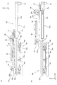
基板搬出装置70は、基板ホルダ40上に載置された基板Pを後述する基板ステージ装置PSTの外部(本実施形態では後述するポート部60(図2参照))に向けて搬出する装置であり、一対のXビーム25のうち、+Y側のXビーム25の外側面(+Y側を向いた面)に取り付けられている。基板搬出装置70は、搬出対象の基板Pの下面を吸着保持する吸着パッド71、吸着パッドを支持する支持部材72、支持部材72(及び吸着パッド71)をX軸方向に直進案内する一対のXリニアガイド装置73、及び支持部材72(及び吸着パッド71)をX軸方向に駆動するためのXリニアモータ74を有している。   The substrate carry-out device 70 is a device that carries the substrate P placed on the substrate holder 40 toward the outside of the substrate stage device PST described later (in the present embodiment, a port unit 60 (see FIG. 2) described later). Of the pair of X beams 25, they are attached to the outer surface of the + Y side X beam 25 (the surface facing the + Y side). The substrate carry-out device 70 is a pair of X that linearly guides the suction pad 71 that sucks and holds the lower surface of the substrate P to be carried out, the support member 72 that supports the suction pad, and the support member 72 (and the suction pad 71) in the X-axis direction. An X linear motor 74 for driving the linear guide device 73 and the support member 72 (and the suction pad 71) in the X-axis direction is provided.

吸着パッド71は、YZ断面L字状の部材から成り、XY平面に平行な部分は、X軸方向を長手方向とする平面視矩形の板状の部材から成る。吸着パッド71は、不図示のバキューム装置に接続されており、上記XY平面に平行な部分の上面が基板吸着面部として機能する。吸着パッド71は、XZ平面に平行な部分の一面が支持部材72の上端部近傍における一面(+Y側を向いた面)に対向している。吸着パッド71は、上記支持部材72の一面に固定されたZリニアガイド75aと、上記XZ平面に平行な部分に固定されたZスライド部材75bとから成るZリニアガイド装置75を介して支持部材72対してZ軸方向に移動可能に取り付けられている。また、吸着パッド71は、支持部材72に取り付けられたZアクチュエータ76により、上面(基板吸着面)が基板ホルダ40の上面よりも+Z側に付き出した位置と基板ホルダ40の上面よりも下がった位置との間でZ軸方向に駆動される。   The suction pad 71 is made of a member having an L-shaped YZ cross section, and the portion parallel to the XY plane is made of a plate-like member having a rectangular shape in plan view with the X-axis direction as the longitudinal direction. The suction pad 71 is connected to a vacuum device (not shown), and the upper surface of a portion parallel to the XY plane functions as a substrate suction surface portion. The suction pad 71 has one surface parallel to the XZ plane facing one surface (surface facing the + Y side) in the vicinity of the upper end portion of the support member 72. The suction pad 71 is supported by a support member 72 via a Z linear guide device 75 including a Z linear guide 75a fixed to one surface of the support member 72 and a Z slide member 75b fixed to a portion parallel to the XZ plane. On the other hand, it is attached to be movable in the Z-axis direction. Further, the suction pad 71 is lowered by the Z actuator 76 attached to the support member 72 so that the upper surface (substrate suction surface) is on the + Z side from the upper surface of the substrate holder 40 and the upper surface of the substrate holder 40. It is driven in the Z-axis direction between the positions.

支持部材72は、Z軸方向に延びるXZ平面に平行な板状の部材から成り、基板Pをポート部60に送り出すために+Z側の端部が−Z側の端部よりも+X側に突き出すように長手方向の中間部が曲げて形成されている。支持部材72の下端部近傍の他面(−Y側を向いた面)は、+Y側のXビーム25の外側面に対向している。これに対し、+Y側のXビーム25の外側面には、Xリニアガイド73aがZ軸方向に所定間隔で、例えば2本(一対)固定されている。また、支持部材72の他面には、上記Xリニアガイド73aにスライド自在に係合するXスライダ73bが複数固定されている。上記Xリニアガイド73aと、Xスライダ73bとにより、支持部材72(及び吸着パッド71)をX軸方向に直進案内するためのXリニアガイド装置73が構成されている。また、上記一対のXリニアガイド73aの間には、X軸方向に所定間隔で配列された複数の永久磁石を含む磁石ユニット74aが固定されている。これに対し、支持部材72の他面には、コイルを含むコイルユニット74bが固定されている。上記磁石ユニット74a(X固定子)と、コイルユニット74b(X可動子)により、支持部材72(及び吸着パッド71)をX軸方向に駆動するためのXリニアモータ74が構成されている。   The support member 72 is formed of a plate-like member parallel to the XZ plane extending in the Z-axis direction, and the + Z side end protrudes to the + X side rather than the −Z side end in order to send the substrate P to the port portion 60. Thus, the middle part in the longitudinal direction is formed by bending. The other surface in the vicinity of the lower end portion of the support member 72 (the surface facing the −Y side) faces the outer surface of the X beam 25 on the + Y side. In contrast, for example, two (a pair) of X linear guides 73a are fixed to the outer surface of the + Y side X beam 25 at a predetermined interval in the Z-axis direction. A plurality of X sliders 73b that are slidably engaged with the X linear guide 73a are fixed to the other surface of the support member 72. The X linear guide 73a and the X slider 73b constitute an X linear guide device 73 for guiding the support member 72 (and the suction pad 71) linearly in the X-axis direction. A magnet unit 74a including a plurality of permanent magnets arranged at a predetermined interval in the X-axis direction is fixed between the pair of X linear guides 73a. On the other hand, a coil unit 74b including a coil is fixed to the other surface of the support member 72. The magnet unit 74a (X stator) and the coil unit 74b (X mover) constitute an X linear motor 74 for driving the support member 72 (and the suction pad 71) in the X-axis direction.

ポート部60は、図2に示されるように、基板ステージ装置PSTの+X側に配置されている。ポート部60は、装置本体30(図2では不図示。図1参照)、及び基板ステージ装置PSTと共に不図示のチャンバ内に収容されている。   As shown in FIG. 2, the port unit 60 is disposed on the + X side of the substrate stage apparatus PST. The port section 60 is housed in a chamber (not shown) together with the apparatus main body 30 (not shown in FIG. 2; see FIG. 1) and the substrate stage apparatus PST.

ポート部60は、露光済みの基板P(図2では基板P)を基板ステージ20から受け取る基板ガイド装置62、及び基板リフト装置68を備えている。基板ガイド装置62は、床11上に設置された架台61上に搭載されている。基板ガイド装置62は、ベース63、及びベース63上に架台64を介して搭載された複数のエア浮上装置65を有している。 The port unit 60 includes a substrate guide device 62 that receives an exposed substrate P (substrate P 1 in FIG. 2) from the substrate stage 20, and a substrate lift device 68. The substrate guide device 62 is mounted on a pedestal 61 installed on the floor 11. The substrate guide device 62 includes a base 63 and a plurality of air levitation devices 65 mounted on the base 63 via a gantry 64.

ベース63は、平面視矩形の板状の部材から成る。ベース63は、架台61の上面に固定されたXリニアガイド66aと、ベース63の下面に固定されたXスライド部材66bとによりそれぞれ構成される複数のXリニアガイド装置66によりX軸方向に直進案内される。また、ベース63は、不図示のXアクチュエータにより架台61に対してX軸方向に所定のストロークで駆動される。後述する基板搬出時を除き、液晶露光装置10の使用時(露光動作時を含む)において、ベース63(基板ガイド装置62)は、図2に示される+X側のストロークエンド(基板ステージ装置PSTから離れた位置)に位置される。   The base 63 is made of a plate-like member having a rectangular shape in plan view. The base 63 is linearly guided in the X-axis direction by a plurality of X linear guide devices 66 each constituted by an X linear guide 66a fixed to the upper surface of the gantry 61 and an X slide member 66b fixed to the lower surface of the base 63. Is done. The base 63 is driven with a predetermined stroke in the X-axis direction with respect to the gantry 61 by an X actuator (not shown). When the liquid crystal exposure apparatus 10 is used (including the exposure operation), except when the substrate is unloaded as described later, the base 63 (substrate guide apparatus 62) moves to the + X side stroke end (from the substrate stage apparatus PST shown in FIG. 2). It is located at a remote location.

複数のエア浮上装置65それぞれは、XY平面に平行な板状部材から成る。エア浮上装置65の上面には、不図示の微少な孔部が複数形成されており、その孔部から加圧気体(例えば、空気)を噴出し、微少な隙間(ギャップ、クリアランス)を介して基板Pを浮上支持することができるようになっている。また、エア浮上装置65の少なくとも一部は、上記複数の孔部(あるいは別の孔部)を用いて基板Pを吸着保持することができるようにもなっている。   Each of the plurality of air levitation devices 65 is composed of a plate-like member parallel to the XY plane. A plurality of minute holes (not shown) are formed on the upper surface of the air levitation device 65, and pressurized gas (for example, air) is ejected from the holes, and through a minute gap (gap, clearance). The substrate P can be levitated and supported. In addition, at least a part of the air levitation device 65 can also hold the substrate P by suction using the plurality of holes (or other holes).

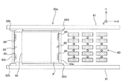
複数のエア浮上装置65は、図4に示されるように、基板Pの下面をほぼ均等に支持できるように、所定間隔で互いに離間して配置されている。本第1の実施形態では、X軸方向に所定間隔で配列された複数(例えば3台)のエア浮上装置65から成るエア浮上装置列が、Y軸方向に所定間隔で複数(例えば5列)配列されている。このように、本第1の実施形態では、基板ガイド装置62は、合計で、例えば15台のエア浮上装置65を用いて基板Pを下方から支持する。なお、エア浮上装置65の配置、及び数については、これに限られず、例えば基板Pの大きさなどに応じて適宜変更可能である。   As shown in FIG. 4, the plurality of air levitation devices 65 are spaced apart from each other at a predetermined interval so that the lower surface of the substrate P can be supported substantially evenly. In the first embodiment, a plurality of (for example, three) air levitation device rows that are arranged at predetermined intervals in the X-axis direction include a plurality of (for example, five) air levitation device rows at predetermined intervals in the Y-axis direction. It is arranged. As described above, in the first embodiment, the substrate guide device 62 supports the substrate P from below using, for example, 15 air levitation devices 65 in total. Note that the arrangement and number of the air levitation devices 65 are not limited to this, and can be changed as appropriate according to the size of the substrate P, for example.

図2に戻り、基板リフト装置68は、上記基板ガイド装置62のベース63上に取り付けられたZアクチュエータ68aと、Zアクチュエータ68aによりZ軸方向に所定のストロークで駆動される複数のリフトピン68bとを備えている。各リフトピン68bは、Z軸方向に延びる棒状の部材から成り、先端部(+Z側の端部)には、基板Pの裏面を保護するためのパッド部材が取り付けられている。複数のリフトピン68bは、図4に示されるように、基板Pの下面をほぼ均等に支持できるように、所定間隔で互いに離間した状態で、上記複数のエア浮上装置65の間に配置されている。本第1の実施形態では、X軸方向に所定間隔で配列された複数(例えば3本)のリフトピン68bから成るリフトピン列が、Y軸方向に所定間隔で複数(例えば4列)配列されている。このように、本第1の実施形態では、基板リフト装置68は、合計で、例えば12台のリフトピン68bを用いて基板Pを下方から支持する。   Returning to FIG. 2, the substrate lift device 68 includes a Z actuator 68a mounted on the base 63 of the substrate guide device 62, and a plurality of lift pins 68b driven by the Z actuator 68a with a predetermined stroke in the Z-axis direction. I have. Each lift pin 68b is made of a rod-shaped member extending in the Z-axis direction, and a pad member for protecting the back surface of the substrate P is attached to the tip portion (the end portion on the + Z side). As shown in FIG. 4, the plurality of lift pins 68 b are arranged between the plurality of air levitation devices 65 in a state of being separated from each other at a predetermined interval so that the lower surface of the substrate P can be supported almost evenly. . In the first embodiment, a plurality (for example, four rows) of lift pin rows each including a plurality of (for example, three) lift pins 68b arranged at predetermined intervals in the X-axis direction are arranged at predetermined intervals in the Y-axis direction. . As described above, in the first embodiment, the substrate lift device 68 supports the substrate P from below by using, for example, 12 lift pins 68b in total.

複数のリフトピン68bは、−Z側の端部が連結部材を介して互いに連結されており、Zアクチュエータ68aにより一体的にZ軸方向に駆動される。Zアクチュエータ68aの種類は、特に限定されないが、例えばエアシリンダなどを用いることができる。なお、基板リフト装置68は、複数のリフトピン68bがひとつのZアクチュエータ68aにより駆動される構成でも良いし、複数のリフトピン68bそれぞれにZアクチュエータが設けられても良い。   The ends of the −Z side of the plurality of lift pins 68b are connected to each other via a connecting member, and are driven integrally in the Z-axis direction by the Z actuator 68a. Although the kind of Z actuator 68a is not specifically limited, For example, an air cylinder etc. can be used. The substrate lift device 68 may be configured such that a plurality of lift pins 68b are driven by a single Z actuator 68a, or each of the plurality of lift pins 68b may be provided with a Z actuator.

基板搬入装置80は、図4に示されるように、一対のX走行ガイド81、一対のX走行ガイド81に対応して設けられた一対の第1Xスライド部材82a、一対のX走行ガイド81に対応して設けられた一対の第2Xスライド部材82b、第1連結バー83a、第2連結バー83b、複数のロードハンド84、複数の支持ピン85、一対のX走行ガイド81に対応して設けられた一対の第3Xスライド部材82c、及び気体吸引装置86を備えている。   As shown in FIG. 4, the substrate carry-in device 80 corresponds to a pair of X travel guides 81, a pair of first X slide members 82 a provided corresponding to the pair of X travel guides 81, and a pair of X travel guides 81. And a pair of second X slide members 82b, a first connection bar 83a, a second connection bar 83b, a plurality of load hands 84, a plurality of support pins 85, and a pair of X travel guides 81. A pair of third X slide members 82c and a gas suction device 86 are provided.

一対のX走行ガイド81は、それぞれX軸方向に延びる部材から成り、Y軸方向に所定間隔(基板PのY軸方向寸法よりも幾分広い間隔)で互いに平行に配置されている。一対のX走行ガイド81のそれぞれは、図2に示されるように、床11上に設定された架台88に複数のZアクチュエータ89を介して搭載されている。Zアクチュエータ89の種類は特に限定されない。   The pair of X traveling guides 81 are each composed of a member extending in the X-axis direction, and are arranged in parallel to each other at a predetermined interval in the Y-axis direction (an interval slightly larger than the dimension in the Y-axis direction of the substrate P). Each of the pair of X traveling guides 81 is mounted on a pedestal 88 set on the floor 11 via a plurality of Z actuators 89, as shown in FIG. The type of the Z actuator 89 is not particularly limited.

架台88は、X軸方向に延びる板状部材から成る天板部88と、床11上で天板部88を下方から支持する一対の脚部88と、一対の脚部88間に架設された補剛部88とを含む。天板部88は、+X側の端部近傍、及び長手方向中央部それぞれが脚部88に下方から支持され、−X側の端部近傍が鏡筒定盤31(図2では不図示。図1参照)に支持部材88を介して吊り下げ支持されている。架台88は、図1に示されるように、一対のX走行ガイド81に対応して一対設けられている。一対の架台88は、図2に示されるように、脚部88の下端部近傍において接続部材88により互いに接続されている(ただし、図2では一方の架台88は不図示)。上記X走行ガイド81は、対応する架台88の天板部88に対して上記Zアクチュエータ89を介して支持されている。なお、X走行ガイド81は、例えば天板部88の全体が上方から吊り下げ支持されても良い。 Cradle 88 includes a top plate portion 88 1 made of a plate-like member extending in the X-axis direction, a pair of leg portions 88 2 that supports the top plate 88 1 from below on the floor 11, a pair of leg portions 88 2 between and a stiffening portion 88 3 which is bridged. Top plate 88 1, + end portion of the X-side, and the longitudinal central portion each is supported from below on the legs 88 2, -X side end near the barrel surface plate 31 (not shown in FIG. 2 . via a supporting member 88 5 is suspended supported see Figure 1). As shown in FIG. 1, the gantry 88 is provided in a pair corresponding to the pair of X traveling guides 81. A pair of frame 88, as shown in FIG. 2, are connected to each other by a connecting member 88 4 in the vicinity of the lower end portion of the leg portion 88 2 (provided that one of the frame 88 in FIG. 2 is not shown). The X running guide 81 is supported through the Z actuator 89 with respect to top plate portion 88 1 of the corresponding frame 88. Incidentally, X running guide 81, for example the whole of the top plate portion 88 1 may be suspended and supported from above.

一対の第1Xスライド部材82aそれぞれは、図4に示されるように、対応するX走行ガイド81に対してX軸方向にスライド可能に係合しており、不図示のXアクチュエータ(例えば送りねじ装置、リニアモータ、ベルト駆動装置、ワイヤ駆動装置など)により、X走行ガイド81に沿って所定のストロークで同期駆動される。一対の第2Xスライド部材82bは、上記一対の第1Xスライド部材82aの−X側に配置されている。一対の第2Xスライド部材82bは、対応するX走行ガイド81に対してX軸方向にスライド可能に係合しており、不図示のXアクチュエータ(例えば送りねじ装置、リニアモータ、ベルト駆動装置など)により、上記第1Xスライド部材82aとは独立して対応するX走行ガイド81に沿って所定のストロークで駆動される。なお、一対の第1Xスライド部材82aをX軸方向に同期駆動できれば、Xアクチュエータが送りねじ装置などである場合に共通のモータにより駆動しても良いし、あるいは一方の第1Xスライド部材82aのみがXアクチュエータにより駆動されても良い(一対の第2Xスライド部材82b、及び後述する第3Xスライド部材82cも同様)。   As shown in FIG. 4, each of the pair of first X slide members 82a is engaged with a corresponding X travel guide 81 so as to be slidable in the X axis direction, and an X actuator (not shown) (for example, a feed screw device). , A linear motor, a belt driving device, a wire driving device, and the like) are synchronously driven along the X travel guide 81 with a predetermined stroke. The pair of second X slide members 82b are disposed on the −X side of the pair of first X slide members 82a. The pair of second X slide members 82b are slidably engaged with the corresponding X travel guide 81 in the X axis direction, and an X actuator (not shown) (for example, a feed screw device, a linear motor, a belt drive device, or the like). Thus, the first X slide member 82a is driven at a predetermined stroke along the corresponding X travel guide 81 independently of the first X slide member 82a. If the pair of first X slide members 82a can be driven synchronously in the X-axis direction, they may be driven by a common motor when the X actuator is a feed screw device or the like, or only one of the first X slide members 82a may be driven. The actuator may be driven by an X actuator (the same applies to a pair of second X slide members 82b and a third X slide member 82c described later).

第1連結バー83aは、Y軸方向に延びる部材から成り、一対の第1Xスライド部材82a間に架設されている。第2連結バー83bは、Y軸方向に延びる部材から成り、一対の第2Xスライド部材82b間に架設されている。基板Pは、基板搬入装置80により基板ステージ20に搬送される際、第1連結バー83aと第2連結バー83bとの間に挿入される。   The first connecting bar 83a is made of a member extending in the Y-axis direction, and is spanned between the pair of first X slide members 82a. The second connection bar 83b is made of a member extending in the Y-axis direction, and is spanned between the pair of second X slide members 82b. When the substrate P is transported to the substrate stage 20 by the substrate carry-in device 80, the substrate P is inserted between the first connection bar 83a and the second connection bar 83b.

本第1の実施形態では、例えば4つのロードハンド84それぞれは、Y軸方向を長手方向とする平面視矩形の板状の部材から成り、基板Pの端部を下方から支持する。例えば4つのロードハンド84のうち、2つは第1連結バー83aにY軸方向に離間して取り付けられ、他の2つは、第2連結バー83bにY軸方向に離間して取り付けられている。例えば4つのロードハンド84それぞれは、不図示のバキューム装置に接続されており、基板Pを吸着保持することができる。   In the first embodiment, for example, each of the four load hands 84 is made of a plate-like member having a rectangular shape in plan view with the Y-axis direction as the longitudinal direction, and supports the end portion of the substrate P from below. For example, of the four load hands 84, two are attached to the first connecting bar 83a with a spacing in the Y-axis direction, and the other two are attached to the second connecting bar 83b with a spacing in the Y-axis direction. Yes. For example, each of the four load hands 84 is connected to a vacuum device (not shown), and can hold the substrate P by suction.

第1の実施形態では、例えば2本の支持ピン85は、X軸方向に延びる円柱状の部材から成り、基板Pの端部を下方から支持する。例えば2本の支持ピン85のうちの一方は、第1連結バー83aの長手方向中央部(例えば2つのロードハンド84の間)に取り付けられ、他方は、第2連結バー83bの長手方向中央部(例えば2つのロードハンド84の間)に取り付けられている。複数のロードハンド84、及び複数の支持ピン85のZ位置は、概ね同じに設定されている。なお、ロードハンド84、及び支持ピン85の配置、及び数については、上記説明したものに限られず、例えば基板Pの大きさなどに応じて適宜変更可能である。また、支持ピン85は、必ずしも設けられていなくても良く、ロードハンド84のみで基板Pを支持しても良い。また、ロードハンド84も、必ずしも設けられていなくても良く、支持ピン85のみで基板Pを支持しても良い。   In the first embodiment, for example, the two support pins 85 are made of a cylindrical member extending in the X-axis direction, and support the end portion of the substrate P from below. For example, one of the two support pins 85 is attached to the longitudinal center of the first connection bar 83a (for example, between the two load hands 84), and the other is the longitudinal center of the second connection bar 83b. (For example, between two road hands 84). The Z positions of the plurality of load hands 84 and the plurality of support pins 85 are set to be substantially the same. Note that the arrangement and the number of the load hands 84 and the support pins 85 are not limited to those described above, and can be appropriately changed according to the size of the substrate P, for example. Further, the support pins 85 are not necessarily provided, and the substrate P may be supported only by the load hand 84. Further, the load hand 84 is not necessarily provided, and the substrate P may be supported only by the support pins 85.

第3Xスライド部材82cは、第1Xスライド部材82aと第2Xスライド部材82bとの間に配置されている。第3Xスライド部材82cは、対応するX走行ガイド81に対してX軸方向にスライド可能に係合しており、不図示のXアクチュエータ(例えば送りねじ装置、リニアモータ、ベルト駆動装置など)により、上記第1Xスライド部材82a、及び第2Xスライド部材82bとは独立して、対応するX走行ガイド81に沿って所定のストロークで駆動される。   The third X slide member 82c is disposed between the first X slide member 82a and the second X slide member 82b. The third X slide member 82c is engaged with the corresponding X travel guide 81 so as to be slidable in the X-axis direction, and by an X actuator (not shown) (for example, a feed screw device, a linear motor, a belt drive device, etc.) The first X slide member 82a and the second X slide member 82b are driven with a predetermined stroke along the corresponding X traveling guide 81 independently of the first X slide member 82a and the second X slide member 82b.

気体吸引装置86は、第1連結バー83aと第2連結バー83bとの間に配置され、一対の第3Xスライド部材82c間に架設されている。気体吸引装置86は、平面視矩形の板状の部材から成り、Y軸方向の寸法が基板PのY軸方向の寸法よりも幾分長く設定され、X軸方向の寸法が基板PのX軸方向の寸法よりも短く(例えば2/3程度に)設定されている。図1及び図2から分かるように、気体吸引装置86の下面のZ位置は、ロードハンド84の上面のZ位置よりも幾分高く設定されており、気体吸引装置86の下面が、X軸方向の両端部が複数のロードハンド84、及び複数の支持ピン85に下方から支持された基板Pの中央部に微少な隙間(ギャップ、クリアランス)を介して対向する。   The gas suction device 86 is disposed between the first connection bar 83a and the second connection bar 83b, and spans between the pair of third X slide members 82c. The gas suction device 86 is composed of a plate-shaped member having a rectangular shape in plan view, and the dimension in the Y-axis direction is set to be slightly longer than the dimension in the Y-axis direction of the substrate P. The dimension in the X-axis direction is set to the X-axis of the substrate P. It is set shorter than the dimension in the direction (for example, about 2/3). As can be seen from FIGS. 1 and 2, the Z position of the lower surface of the gas suction device 86 is set somewhat higher than the Z position of the upper surface of the load hand 84, and the lower surface of the gas suction device 86 is set in the X-axis direction. Both end portions of the substrate face the central portion of the substrate P supported by the plurality of load hands 84 and the plurality of support pins 85 from below via a small gap (gap, clearance).

気体吸引装置86の下面(基板Pの上面に対する対向面)には、不図示の孔部が複数形成されている。気体吸引装置86は、不図示のバキューム装置に接続されており、上記複数の孔部を介して基板Pとの間の気体を吸引することにより、基板Pに対して鉛直方向上向き(+Z方向)の力を作用させる。これにより、基板Pの中央部の自重に起因する撓み量を制御することができる。   A plurality of holes (not shown) are formed on the lower surface of the gas suction device 86 (the surface facing the upper surface of the substrate P). The gas suction device 86 is connected to a vacuum device (not shown), and sucks the gas between the substrate P and the substrate P through the plurality of holes, so that the gas suction device 86 faces upward in the vertical direction (+ Z direction). Apply the power of. Thereby, the bending amount resulting from the dead weight of the center part of the board | substrate P is controllable.

ここで、気体吸引装置86の吸引力(基板Pに作用させる鉛直方向上向きの力)は、基板Pの上面(レジスト層)を保護するために、気体吸引装置86の下面と基板Pの上面とが接触しない程度に設定されている。なお、気体吸引装置86は、基板Pの中央部の撓みを抑制することができれば良く、基板Pが厳密に水平面と平行になるように圧力制御を行う必要はない。また、気体吸引装置86は、上記バキューム装置を用いた気体の吸引動作と併せて、基板Pの上面に気体を噴出することにより、基板Pとの接触を防止しても良い。   Here, the suction force of the gas suction device 86 (the upward force acting on the substrate P) is applied to the lower surface of the gas suction device 86 and the upper surface of the substrate P in order to protect the upper surface (resist layer) of the substrate P. Is set to the extent that does not touch. The gas suction device 86 only needs to be able to suppress the bending of the central portion of the substrate P, and does not need to perform pressure control so that the substrate P is strictly parallel to the horizontal plane. Further, the gas suction device 86 may prevent contact with the substrate P by ejecting gas onto the upper surface of the substrate P in conjunction with the gas suction operation using the vacuum device.

上述のようにして構成された液晶露光装置10(図1参照)では、不図示の主制御装置の管理の下、不図示のマスクローダによって、マスクステージMST上へのマスクMのロードが行われるとともに、基板搬入装置80によって、基板ホルダ40上への基板Pのロードが行なわれる。その後、主制御装置により、不図示のアライメント検出系を用いてアライメント計測が実行され、そのアライメント計測の終了後、基板上に設定された複数のショット領域に逐次ステップ・アンド・スキャン方式の露光動作が行なわれる。なお、この露光動作は従来から行われているステップ・アンド・スキャン方式の露光動作と同様であるので、その詳細な説明は省略するものとする。そして、露光処理が終了した基板が基板搬出装置70により基板ホルダ40上からポート部60に搬出されるとともに、次に露光される別の基板が基板ホルダ40に搬送されることにより、基板ホルダ40上の基板の交換が行われ、複数の基板に対し、露光動作などが連続して行われる。   In the liquid crystal exposure apparatus 10 (see FIG. 1) configured as described above, the mask M is loaded onto the mask stage MST by a mask loader (not shown) under the control of the main controller (not shown). At the same time, the substrate loading device 80 loads the substrate P onto the substrate holder 40. After that, alignment measurement is performed by the main controller using an alignment detection system (not shown), and after the alignment measurement, a step-and-scan exposure operation is sequentially performed on a plurality of shot areas set on the substrate. Is done. Since this exposure operation is the same as a conventional step-and-scan exposure operation, a detailed description thereof will be omitted. Then, the substrate after the exposure processing is carried out from the substrate holder 40 to the port unit 60 by the substrate carry-out device 70, and another substrate to be exposed next is carried to the substrate holder 40, whereby the substrate holder 40. The upper substrate is exchanged, and the exposure operation and the like are continuously performed on the plurality of substrates.

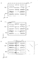
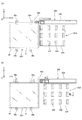
以下、液晶露光装置10における基板ホルダ40上の基板P(便宜上、複数の基板Pを基板P、基板P、基板Pと称する)の交換動作について図5(A)〜図12(B)に基いて説明する。以下の基板交換動作は、不図示の主制御装置の管理の下に行われる。図5(A)において、基板ホルダ40には、露光済みの基板Pが保持され、基板搬入装置80は、基板Pの次に露光処理が行われる予定の別の基板Pが保持されている。 Hereinafter, the exchange operation of the substrate P on the substrate holder 40 in the liquid crystal exposure apparatus 10 (for convenience, a plurality of substrates P will be referred to as substrate P 1 , substrate P 2 , and substrate P 3 ) will be described with reference to FIGS. ). The following board replacement operation is performed under the control of a main controller (not shown). In FIG. 5 (A), the substrate holder 40 is held exposed substrate P 1 is a substrate carry-in device 80 may be another substrate P 2 is held scheduled to next exposure processing of the substrate P 1 is carried out ing.

基板Pに対する露光が終了すると、基板ステージ20は、基板Pの搬出動作のために、基板ホルダ40が図5(A)に示される基板交換位置に位置するようにY粗動ステージ23y及びX粗動ステージ23xが制御される。基板交換位置に位置した状態で、基板ホルダ40の上面のZ位置は、基板ガイド装置62が有する複数のエア浮上装置65の上面のZ位置と概ね一致するように制御される。また、基板ステージ20が有する基板搬出装置70は、図11(A)に示されるように、吸着パッド71が基板ホルダ40の−X側の端部近傍に隣接するように位置決めされる。図5(A)に戻り、基板Pは、基板搬入装置80の複数のロードハンド84に支持された状態で、基板交換位置の上方で予め待機している。また、ポート部60の基板ガイド装置62は、−X側のストロークエンドに位置決めされる。 When the exposure for the substrate P 1 is completed, the substrate stage 20, for the unloading operation the substrate P 1, Y coarse movement stage 23y and as the substrate holder 40 is positioned at the substrate exchange position shown in FIG. 5 (A) The X coarse movement stage 23x is controlled. The Z position on the upper surface of the substrate holder 40 is controlled so as to substantially coincide with the Z positions on the upper surfaces of the plurality of air levitation devices 65 included in the substrate guide device 62 in the state of being located at the substrate replacement position. Further, the substrate carry-out device 70 included in the substrate stage 20 is positioned so that the suction pad 71 is adjacent to the vicinity of the end portion on the −X side of the substrate holder 40 as shown in FIG. Returning to FIG. 5A, the substrate P 2 is waiting in advance above the substrate replacement position while being supported by the plurality of load hands 84 of the substrate carry-in device 80. Further, the board guide device 62 of the port portion 60 is positioned at the stroke end on the −X side.

次いで、図5(B)に示されるように、基板ホルダ40上の基板Pが基板搬出装置70によりポート部60の基板ガイド装置62上に搬出される。基板Pの搬出の際、基板ホルダ40では、図11(A)に示されるように、一対の基板スライド装置45それぞれの吸着パッド45aが+Z方向に駆動され、基板Pの下面を吸着保持する。また、基板ホルダ40の上面からは、加圧気体が噴出され、基板Pが基板ホルダ40上で浮上する。この状態で図11(B)に示されるように、吸着パッド45aが+Y方向に駆動され、基板Pが基板ホルダ40に対して+Y方向に駆動される。これにより、基板Pの+Y側の端部近傍が基板ホルダ40の+Y側の端部から突き出し(はみ出し)、基板搬出装置70の吸着パッド71と上下方向に重なる。次いで、吸着パッド71が+Z方向に駆動され、基板Pの+Y側且つ−X側の隅部が吸着パッド71に吸着保持される。 Next, as shown in FIG. 5B, the substrate P 1 on the substrate holder 40 is unloaded onto the substrate guide device 62 of the port section 60 by the substrate unloading device 70. During unloading of the substrate P 1, the substrate holder 40, as shown in FIG. 11 (A), each of the suction pads 45a pair of substrates sliding device 45 is driven in the + Z direction, the suction holding the lower surface of the substrate P 1 To do. Further, pressurized gas is ejected from the upper surface of the substrate holder 40, and the substrate P 1 floats on the substrate holder 40. As shown in FIG. 11 (B) in this state, the suction pad 45a is driven in the + Y direction, the substrate P 1 is driven in the + Y direction with respect to the substrate holder 40. Thus, near the end portion on the + Y side of the substrate P 1 is (protruding) protrudes from the end portion on the + Y side of the substrate holder 40, overlaps with the suction pads 71 of the substrate carry-out device 70 in the vertical direction. Next, the suction pad 71 is driven in the + Z direction, and the corners on the + Y side and the −X side of the substrate P 1 are sucked and held by the suction pad 71.

この後、図11(C)に示されるように、吸着パッド45aによる基板Pの吸着保持が解除されるとともに、吸着パッド71が+X方向に駆動される。これにより、基板Pが基板ホルダ40の上面に沿って移動し、図5(B)に示されるように、ポート部60の基板ガイド装置62上に搬出される。このため、基板ホルダ40は、基板交換位置に位置決めされる際、Y軸方向に関する中心位置が、ポート部60が有する基板ガイド装置62のY軸方向に関する中心に対して、幾分−Y側にずれるように予め配置される。吸着パッド45aは、基板Pの搬入に備えて、図11(C)に示されるように、−Z方向に駆動された後、−Y方向に駆動される(初期位置に戻される)。 Thereafter, as shown in FIG. 11 (C), together with the suction holding of the substrate P 1 is released by the
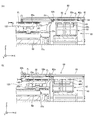
 suction pads 45a, are driven in the suction pad 71 is the + X direction. Accordingly, the substrate P 1 is moved along the upper surface of the substrate holder 40, as shown in FIG. 5 (B), it is carried out onto the substrate guide device 62 for ports 60. Therefore, when the substrate holder 40 is positioned at the substrate replacement position, the center position in the Y-axis direction is somewhat on the −Y side with respect to the center in the Y-axis direction of the substrate guide device 62 included in the port portion 60. Prearranged so as to shift. Suction pads 45a are provided on the loading of the substrate P 2, as shown in FIG. 11 (C), after being driven in the -Z direction, (is returned to the initial position) which is driven in the -Y direction.

基板Pが基板ホルダ40から搬出されると、基板ガイド装置62は、図6(A)に示されるように、複数のエア浮上装置65を用いて基板Pを吸着保持し、その状態で+X方向(基板ステージ20から離れる方向)に駆動される。また、基板ステージ20では、基板搬出装置70の吸着パッド71が−Z方向に駆動される。 When the substrate P 1 is unloaded from the substrate holder 40, substrate guide device 62, as shown in FIG. 6 (A), and sucking and holding the substrate P 1 using a plurality of air floating device 65, in this state It is driven in the + X direction (direction away from the substrate stage 20). In the substrate stage 20, the suction pad 71 of the substrate carry-out device 70 is driven in the −Z direction.

次に、基板搬入装置80を用いて、基板Pが基板ホルダ40上に搬入される。基板搬入装置80では、図6(B)に示されるように、複数のZアクチュエータ89(図6(B)ではX走行ガイド81の紙面奥側に隠れており不図示。図6(A)参照)により、X走行ガイド81が下降駆動される。これにより、X走行ガイド81に支持された複数のロードハンド84、及び気体吸引装置86が−Z方向に移動する。 Next, the substrate P 2 is carried onto the substrate holder 40 using the substrate carry-in device 80. In the substrate carry-in device 80, as shown in FIG. 6 (B), a plurality of Z actuators 89 (in FIG. 6 (B), hidden behind the paper surface of the X travel guide 81 are not shown. See FIG. 6 (A)). ), The X travel guide 81 is driven downward. As a result, the plurality of load hands 84 and the gas suction device 86 supported by the X traveling guide 81 move in the −Z direction.

ここで、基板搬入装置80では、基板交換位置に位置した基板ホルダ40に対して、図12(A)に示されるように、複数のロードハンド84のそれぞれが対応する切り欠き41の上方に、2つ(一対)の支持ピン85のそれぞれが対応する切り欠き42の上方に、それぞれ位置するように(X及びY位置が同じとなるように)、各一対の第1及び第2Xスライド部材82a、82b(図12(A)では不図示。図6(B)参照)が位置決めされている。このため、図6(B)に示されるように、一対のX走行ガイド81が下降駆動されると、図12(A)に示されるように、複数のロードハンド84のそれぞれが対応する切り欠き41内に、一対の支持ピン85のそれぞれが対応する切り欠き42内に、それぞれ挿入されるとともに、複数のロードハンド84、及び一対の支持ピン85に下方から支持された基板Pが基板ホルダ40の上面に載置される。 Here, in the substrate carry-in device 80, with respect to the substrate holder 40 located at the substrate replacement position, as shown in FIG. 12A, each of the plurality of load hands 84 is above the corresponding notch 41, Each pair of first and second X slide members 82a is arranged such that each of the two (a pair of) support pins 85 is positioned above the corresponding notch 42 (the X and Y positions are the same). , 82b (not shown in FIG. 12A, see FIG. 6B). Therefore, as shown in FIG. 6 (B), when the pair of X traveling guides 81 is driven downward, as shown in FIG. 12 (A), each of the plurality of road hands 84 corresponds to the notch. in 41, the notch 42 each of the pair of support pins 85 the corresponding, with respectively inserted, the substrate P 2 is a substrate holder which is supported from below a plurality of load hand 84 and a pair of support pins 85, 40 is placed on the upper surface.

また、基板Pを基板ホルダ40上に載置する際(本実施形態では、基板Pをポート部60の上方から基板交換位置の上方に搬送する際も含む)、基板搬入装置80では、基板Pの中央部(気体吸引装置86による+Z方向の力が作用する部分)がX軸方向に関する両端部(ロードハンド84により支持される部分)よりも幾分下方(−Z方向)に張り出す(垂れ下がる)ように、気体吸引装置86による気体の吸引圧(吸引力)が制御される。このため、基板Pが基板ホルダ40に載置される際、該基板Pは、最初に中央部が基板ホルダ40の上面に当接し、次いで中央部からX軸方向に関する両端部に向かって内側から外側の順に基板ホルダ40に当接する。 Also, when placing the substrate P 2 on the substrate holder 40 (in the present embodiment also includes the time of transporting the substrate P 2 from above the port portion 60 above the substrate exchange position), the substrate carry-in device 80, tension in the central portion of the substrate P 2 both end portions (portions with the gas suction apparatus 86 + Z direction is exerted) is the X-axis directions slightly downward (-Z direction) than (a portion supported by the load hand 84) The suction pressure (suction force) of the gas by the gas suction device 86 is controlled so that the gas is sucked out (hangs down). For this reason, when the substrate P 2 is placed on the substrate holder 40, the central portion of the substrate P 2 first comes into contact with the upper surface of the substrate holder 40, and then from the central portion toward both ends in the X-axis direction. It contacts the substrate holder 40 in order from the inside to the outside.

基板Pが基板ホルダ40に載置されると、複数のロードハンド84による基板Pの吸着保持が解除されるとともに、複数のロードハンド84及び一対の支持ピン85それぞれが基板Pから離間するまで、図6(B)に示されるように、X走行ガイド81が下降駆動される。また、気体吸引装置86による気体の吸引は停止され、基板ホルダ40は、基板Pを吸着保持する。 When the substrate P 2 is placed on the substrate holder 40, spaced with a suction holding the substrate P 2 by the plurality of load hand 84 is released, each of the plurality of load hand 84 and a pair of support pins 85 from the substrate P 2 Until then, the X travel guide 81 is driven downward as shown in FIG. The suction of the gas by the gas suction device 86 is stopped, the substrate holder 40 attracts and holds the substrate P 2.

また、上記基板搬入装置80から基板ステージ20への基板Pの受け渡し動作と並行して、ポート部60では、複数のエア浮上装置65による基板Pの吸着保持が解除されるとともに、複数のリフトピン68bが上昇駆動される(図6(B)参照)。これにより、複数のリフトピン68bの先端部が基板Pの下面に当接し、基板Pが複数のエア浮上装置65から持ち上げられる。 In parallel with the transfer operation of the substrate P 2 from the substrate carry-in device 80 to the substrate stage 20, in the port unit 60, the suction holding of the substrate P 1 by the plurality of air levitation devices 65 is released, and a plurality of operations are performed. The lift pin 68b is driven up (see FIG. 6B). Thus, the tip portions of the plurality of lift pins 68b abut against the lower surface of the substrate P 1, the substrate P 1 is lifted from a plurality of air floating devices 65.

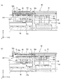
次いで、基板搬入装置80では、図7(A)に示されるように、第1Xスライド部材82aが+X方向に、第2Xスライド部材82bが−X方向にそれぞれ駆動される。これにより、図12(B)に示されるように、各ロードハンド84が対応する切り欠き41内から、各支持ピン85が対応する切り欠き42内から、それぞれ離脱する。図7(A)に戻り、ポート部60では、基板Pと複数のエア浮上装置65との間に、例えば米国特許第7,520,545号明細書などに開示されるような外部搬送ロボットの搬出用ハンド部材19aが挿入される。搬出用ハンド部材19aは、−X側の端部に開口する複数(本実施形態では、複数のリフトピン68bに対応する間隔でY軸方向に所定間隔で、例えば4つ)の切り欠きが形成されたフォーク状の部材から成り、上記切り欠き内にリフトピン68bが挿入される。 Next, in the substrate carry-in device 80, as shown in FIG. 7A, the first X slide member 82a is driven in the + X direction and the second X slide member 82b is driven in the -X direction. As a result, as shown in FIG. 12B, each load hand 84 is detached from the corresponding cutout 41 and each support pin 85 is detached from the corresponding cutout 42. Returning in FIG. 7 (A), the port unit 60, an external transfer robot, as disclosed in, for example, in US Patent No. 7,520,545 between the substrate P 1 and a plurality of air floating devices 65 The unloading hand member 19a is inserted. The carry-out hand member 19a is formed with a plurality of cutouts (in this embodiment, four at a predetermined interval in the Y-axis direction at intervals corresponding to the plurality of lift pins 68b, for example) that open at the −X side end. The lift pin 68b is inserted into the notch.

この後、図7(B)に示されるように、基板搬入装置80の一対のX走行ガイド81が上昇駆動され、これにより複数のロードハンド84、及び一対の支持ピン85(図7(B)では不図示。図12(A)参照)が、基板Pの上面よりも高い(+Z側の)位置に退避する。また、ポート部60では、搬出用ハンド部材19aが+Z方向に駆動された後に+X方向に駆動されることにより、基板Pを複数のリフトピン68bから持ち上げて外部装置(例えばコータデベロッパ装置)に向けて搬送する。 Thereafter, as shown in FIG. 7 (B), the pair of X traveling guides 81 of the substrate carry-in device 80 are driven up, thereby a plurality of load hands 84 and a pair of support pins 85 (FIG. 7 (B)). in not shown. FIG. 12 (a) refer) is retracted to) position higher than the upper surface of the substrate P 2 (+ Z side. Furthermore, the port portion 60, by being driven in the + X direction after unloading hand member 19a is driven in the + Z direction, towards the external device (e.g., a coater developer apparatus) Lift the substrate P 1 from a plurality of lift pins 68b Transport.

基板Pを吸着保持した基板ホルダ40は、図8(A)に示されるように、基板Pに対するアライメント処理、及び露光処理のためにポート部60から離れる方向に駆動される。以下、アライメント処理中、及び露光処理中の基板ステージ20の動作については説明を省略する。また、ポート部60では、複数のエア浮上装置65の上方であって、基板搬入装置80の一対(図8(A)では一方は不図示。図4参照)のX走行ガイド81間に、基板Pの次に露光される予定の基板Pを下方から支持した外部搬送ロボットの搬入用ハンド部材19bが挿入される。搬入用ハンド部材19bは、搬出用ハンド部材19a(図8(A)では不図示。図7(A)参照)と概ね同じ構成を有しており、切り欠き内にリフトピン68bが挿入される。次いで、図8(B)に示されるように、搬入用ハンド部材19bが−Z方向に駆動された後に+X方向に駆動されることにより、基板Pが複数のリフトピン68bに受け渡される。なお、上記外部搬送ロボット(搬出用ハンド部材19a及び搬入用ハンド部材19b)とポート部60(リフトピン68b)との間における基板の受け渡し動作において、搬出用ハンド部材19a及び搬入用ハンド部材19bを上下動させるのに換えて、リフトピン68bを上下動させても良い。 Substrate holder 40 to the substrate P 2 sucked and held, as shown in FIG. 8 (A), the alignment process for the substrate P 2, and is driven in a direction away from the port portion 60 for exposure process. Hereinafter, the description of the operation of the substrate stage 20 during the alignment process and during the exposure process will be omitted. Further, in the port portion 60, the substrate is located above the plurality of air levitation devices 65 and between the pair of X traveling guides 81 of the substrate carry-in device 80 (one is not shown in FIG. 8A, see FIG. 4). carry-hand member 19b of the external transfer robot supporting the substrate P 3 that will be next to the exposure of P 2 from below is inserted. The carry-in hand member 19b has substantially the same structure as the carry-out hand member 19a (not shown in FIG. 8A, see FIG. 7A), and lift pins 68b are inserted into the notches. Then, as shown in FIG. 8 (B), by carrying hand member 19b is driven in the + X direction after being driven in the -Z direction, the substrate P 3 is passed to a plurality of lift pins 68b. In the substrate transfer operation between the external transfer robot (the unloading hand member 19a and the loading hand member 19b) and the port portion 60 (lift pin 68b), the unloading hand member 19a and the loading hand member 19b are moved up and down. Instead of moving, the lift pin 68b may be moved up and down.

次いで、図9(A)に示されるように、基板Pの上面のZ位置が、複数のロードハンド84、及び一対の支持ピン85(図9(A)では不図示。図4参照)の下面のZ位置よりも低くなるように、複数のリフトピン68bが幾分下降駆動される。また、各一対の第1〜第3Xスライド部材82a〜82cそれぞれが+X方向に駆動され、これにより、複数のロードハンド84と気体吸引装置86とがポート部60の上方に移動する。この際、複数のロードハンド84と基板Pとが上下方向に重ならないように、各一対の第1及び第2Xスライド部材82a、82bが位置決めされる。 Then, as shown in FIG. 9 (A), Z position of the upper surface of the substrate P 3 is a plurality of load hand 84, and a pair of support pins 85 (see FIG. 9 (A) not shown. FIG. 4) The plurality of lift pins 68b are driven somewhat downward so as to be lower than the Z position on the lower surface. In addition, each of the pair of first to third X slide members 82 a to 82 c is driven in the + X direction, whereby the plurality of load hands 84 and the gas suction device 86 move above the port portion 60. At this time, as the multiple load hand 84 and the substrate P 3 does not overlap in the vertical direction, each pair of first and 2X slide member 82a, 82b is positioned.

この後、図9(B)に示されるように、複数のリフトピン68bが、基板Pの下面のZ位置が複数のロードハンド84、及び一対の支持ピン85(図9(B)では不図示。図4参照)の上面のZ位置よりも高くなるように(ただし基板Pと気体吸引装置86とが接触しないように)上昇駆動される。この後、一対の第1Xスライド部材82aが−X方向に、一対の第2Xスライド部材82bが+X方向にそれぞれ駆動されることにより、複数のロードハンド84が基板Pの下方に挿入される。この際、複数のリフトピン68bを用いて基板Pを上昇駆動するのに換えて、X走行ガイド81を下降駆動しても良い。 Thereafter, as shown in FIG. 9 (B), a plurality of lift pins 68b is the lower surface of the Z position is a plurality of load hand 84 of the substrate P 3, and a pair of support pins 85 (FIG. 9 (B), the unshown . Figure 4 as to be higher than the Z position of the upper surface of the reference) (provided that the substrate P 3 and the gas suction device 86 does not contact) is driven upward. Thereafter, the pair of the 1X sliding member 82a is the -X direction, by a pair of the 2X sliding member 82b is driven respectively in the + X direction, a plurality of load hand 84 is inserted under the substrate P 3. At this time, instead to increase drives the substrate P 3 using a plurality of lift pins 68b, may be lowered driving the X running guide 81.

次いで、図10(A)に示されるように、複数のリフトピン68bが下降駆動され、これにより基板PのX軸方向に関する両端部が複数のロードハンド84及び一対の支持ピン85(図10(A)では不図示。図4参照)に下方から支持される。また、これと並行して気体吸引装置86が基板Pとの間の気体を吸引し、基板Pの中央部に+Z方向の力を作用させる。これにより、基板Pが水平面(XY平面)に対してほぼ平行となる。 Then, as shown in FIG. 10 (A), a plurality of lift pins 68b are driven downward, thereby the substrate P 3 in the X-axis direction end portions are a plurality of load hand 84 and a pair of support pins 85 about (FIG. 10 ( In A), it is not shown (see FIG. 4) and is supported from below. Further, in parallel with this gas suction apparatus 86 sucks the gas between the substrate P 3, applying a force in the central portion in the + Z direction of the substrate P 3. Accordingly, the substrate P 3 is substantially parallel to the horizontal plane (XY plane).

この後、図10(B)に示されるように、各一対の第1〜第3Xスライド部材82a〜82cそれぞれが−X方向に駆動され、これにより、基板Pが基板交換位置の上方の位置へ水平面に沿って搬送される。上記図8(A)〜図10(B)に示される基板Pの搬送動作(外部からポート部60への搬入動作、及びポート部60から基板交換位置の上方の位置への搬送動作)は、基板Pに対するアライメント処理、及び露光処理と並行して行われる。 Thereafter, as shown in FIG. 10 (B), each of the pair of first through 3X slide member 82a~82c is driven in the -X direction, whereby the position the substrate P 3 is above the substrate exchange position It is conveyed along the horizontal plane. FIG 8 (A) ~ FIG 10 (B) conveying operation of the substrate P 3 shown in (loading operation from the outside to the port portion 60, and the conveying operation of the port portion 60 to a position above the substrate exchange position) , the alignment process for the substrate P 2, and is performed in parallel with the exposure process.

以上説明した第1の実施形態に係る基板搬入装置80は、気体吸引装置86が基板P上面側に配置されているので、基板Pを直接的に基板ホルダ40の基板載置面上に載置することができる。従って、基板ステージ20(特に基板ホルダ40の基板載置面)に基板Pを受け取るための装置及び部材(例えばリフトピン装置)を設ける必要がなく、基板ステージ20の制御性、及び基板ホルダ40に保持された基板Pの平坦性が向上する。また、気体吸引装置86が基板P上面側に配置されているので、ポート部60において、複数のリフトピン68bに下方から支持された基板Pを直接的に受け取ることができる。   In the substrate carry-in device 80 according to the first embodiment described above, since the gas suction device 86 is arranged on the upper surface side of the substrate P, the substrate P is directly placed on the substrate placement surface of the substrate holder 40. can do. Therefore, it is not necessary to provide a device and a member (for example, a lift pin device) for receiving the substrate P on the substrate stage 20 (particularly the substrate mounting surface of the substrate holder 40), and the controllability of the substrate stage 20 and the substrate holder 40 are held. The flatness of the substrate P is improved. Further, since the gas suction device 86 is disposed on the upper surface side of the substrate P, the port portion 60 can directly receive the substrate P supported by the plurality of lift pins 68b from below.

さらに、基板搬入装置80は、基板Pに対して上方から非接触で+Z方向(鉛直方向上向き)の力を作用させることにより、基板Pの撓み量を制御できるので、基板Pの中央部を幾分下方に張り出させた状態で基板ホルダ40上に載置することができる。このため、基板Pは、最初に中央部が基板ホルダ40の上面に当接し、次いで中央部からX軸方向に関する両端部に向けて順に基板ホルダ40に当接し、基板Pと基板ホルダ40との間の空気が基板ホルダ40の中央から+X側、及び−X側の端部に向けて押し出される。従って、基板Pと基板ホルダ40との間に、いわゆる空気溜まりが形成されることが防止される。   Further, the substrate carry-in device 80 can control the amount of bending of the substrate P by applying a force in the + Z direction (vertical direction upward) to the substrate P from the upper side without contact with the substrate P. It can be placed on the substrate holder 40 in a state of projecting downward by a minute. For this reason, the substrate P first comes into contact with the upper surface of the substrate holder 40, and then comes into contact with the substrate holder 40 in order from the center toward both ends in the X-axis direction. The air between them is pushed out from the center of the substrate holder 40 toward + X side and −X side ends. Therefore, a so-called air pocket is prevented from being formed between the substrate P and the substrate holder 40.

また、基板搬入装置80は、基板Pの+X側の端部を下方から支持する一対のロードハンド84と、基板Pの−X側の端部を下方から支持する一対のロードハンド84とのX位置を独立して制御できる(基板Pのサイズに応じて互いの間隔を任意に変更できる)ので、大きさの異なる複数の基板が露光対象となる場合であっても、容易にポート部60から基板ホルダ40に対して基板Pを搬送できる。   The substrate carry-in device 80 includes a pair of load hands 84 that support the + X side ends of the substrate P from below and a pair of load hands 84 that support the −X side ends of the substrate P from below. Since the position can be controlled independently (the interval between the substrates P can be arbitrarily changed according to the size of the substrate P), even when a plurality of substrates having different sizes are to be exposed, it is easily controlled from the port unit 60. The substrate P can be transferred to the substrate holder 40.

《第2の実施形態》
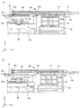
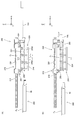
次に第2の実施形態について図13(A)〜図22(B)に基いて説明する。第2の実施形態に係る液晶露光装置の構成は、基板ステージ120の構成が異なる点を除き、上記第1の実施形態と同じであるので、以下、上記第1の実施形態と同様の構成、及び機能を有する要素については、上記第1の実施形態と同じ符号を用いてその説明を省略する。また、図13(A)に示されるように、基板ステージ120の構成は、基板ホルダ140、基板搬出装置170を除き、上記第1の実施形態と同じであるので、以下、相違点についてのみ説明する。
<< Second Embodiment >>
Next, a second embodiment will be described based on FIGS. 13 (A) to 22 (B). Since the configuration of the liquid crystal exposure apparatus according to the second embodiment is the same as that of the first embodiment except that the configuration of the substrate stage 120 is different, the configuration similar to that of the first embodiment will be described below. And about the element which has a function, the description is abbreviate | omitted using the same code | symbol as the said 1st Embodiment. Further, as shown in FIG. 13A, the configuration of the substrate stage 120 is the same as that of the first embodiment except for the substrate holder 140 and the substrate carry-out device 170. Therefore, only the differences will be described below. To do.

基板ホルダ140は、図13(A)及び図13(B)から分かるように、複数の基板リフト装置46を有している。各基板リフト装置46は、図13(A)に示されるように、エア浮上装置46aと、エア浮上装置46aをZ軸方向に駆動するZアクチュエータ46bとを備えている。基板ホルダ140の上面には、図13(B)に示されるように、複数の基板リフト装置46に対応してX軸方向に延びるX溝46cが複数形成されており、複数の基板リフト装置46それぞれは、対応するX溝46c内に収容されている。本第2の実施形態に係る基板ホルダ140は、Y軸方向に所定間隔で配列された、例えば5台の基板リフト装置46から成る基板リフト装置列を、X軸方向に所定間隔で、例えば3列有しており、合計で、例えば15台の基板リフト装置46を有している。なお、基板リフト装置46の数、及び配置は、これに限られず、例えば基板Pの大きさなどに応じて適宜変更が可能である。   As can be seen from FIGS. 13A and 13B, the substrate holder 140 has a plurality of substrate lift devices 46. As shown in FIG. 13A, each substrate lift device 46 includes an air levitation device 46a and a Z actuator 46b that drives the air levitation device 46a in the Z-axis direction. As shown in FIG. 13B, a plurality of X grooves 46 c extending in the X-axis direction corresponding to the plurality of substrate lift devices 46 are formed on the upper surface of the substrate holder 140. Each is accommodated in the corresponding X groove 46c. In the substrate holder 140 according to the second embodiment, a substrate lift device array composed of, for example, five substrate lift devices 46 arranged at a predetermined interval in the Y-axis direction is arranged at a predetermined interval in the X-axis direction, for example, 3 In total, for example, 15 substrate lift devices 46 are provided. The number and arrangement of the substrate lift devices 46 are not limited to this, and can be appropriately changed according to the size of the substrate P, for example.

エア浮上装置46aは、X軸方向に延びる板状の部材から成り、上面に形成された複数の微細な孔部から加圧気体を噴出することにより、基板Pを浮上させることができる。エア浮上装置46aは、上面が基板ホルダ140の上面よりも+Z側に突き出した位置と、基板ホルダ140の上面よりも−Z側に下がった(引っ込んだ)位置との間でZアクチュエータ46bにより駆動される。これにより、基板リフト装置46は、基板Pの下面を基板ホルダ140の上面から離間させることができる。Zアクチュエータの種類は、特に限定されないが、例えばエアシリンダ、カム装置、送りねじ装置などを用いることができる。なお、本第2の実施形態では、基板ホルダ140内にZアクチュエータ46bが内蔵されているが、Zアクチュエータ46bは、これに限られず、例えば微動ステージ21、あるいはX粗動ステージ23xに設けられていても良い。   The air levitation device 46a is made of a plate-like member extending in the X-axis direction, and can levitate the substrate P by ejecting pressurized gas from a plurality of fine holes formed on the upper surface. The air levitation device 46a is driven by the Z actuator 46b between a position where the upper surface protrudes to the + Z side from the upper surface of the substrate holder 140 and a position where the upper surface of the substrate holder 140 is lowered (retracted) to the −Z side. Is done. Accordingly, the substrate lift device 46 can separate the lower surface of the substrate P from the upper surface of the substrate holder 140. Although the kind of Z actuator is not specifically limited, For example, an air cylinder, a cam apparatus, a feed screw apparatus etc. can be used. In the second embodiment, the Z actuator 46b is built in the substrate holder 140. However, the Z actuator 46b is not limited to this, and is provided, for example, on the fine movement stage 21 or the X coarse movement stage 23x. May be.

基板搬出装置170は、吸着パッド71及びZアクチュエータ76が支持部材72の−Y側(基板ホルダ40側)の面部に取り付けられている点が上記第1の実施形態(図1参照)と異なる。これにより、本第2の実施形態における基板搬出装置170は、図13(A)に示されるように、吸着パッド71の−Y側の端部近傍の領域を基板ホルダ140の+Y側の端部近傍の領域と上下方向に重ねて配置させることができる。   The substrate carry-out device 170 is different from the first embodiment (see FIG. 1) in that the suction pad 71 and the Z actuator 76 are attached to the surface portion of the support member 72 on the −Y side (substrate holder 40 side). Accordingly, the substrate carry-out device 170 according to the second embodiment is configured so that the region near the end portion on the −Y side of the suction pad 71 is the end portion on the + Y side of the substrate holder 140 as shown in FIG. It can be arranged so as to overlap with a nearby region in the vertical direction.

吸着パッド71は、図14(A)に示されるように、基板Pに対するアライメント処理中、あるいは露光処理中など、基板ホルダ40がY粗動ステージ23y(図14(A)では不図示。図13(A)参照)上でX軸方向に所定のストロークで駆動される際には、基板ホルダ40の移動可能範囲外に退避して配置される。そして、吸着パッド71は、基板Pを搬出する際には、図14(B)に示されるように、基板リフト装置46(図14(B)では不図示。図13(A)参照)により基板ホルダ140から持ち上げられた基板Pの下面と基板ホルダ140の上面との間に挿入(図13(A)参照)される。   As shown in FIG. 14A, the suction pad 71 has the substrate holder 40 in the Y coarse movement stage 23y (not shown in FIG. 14A), such as during alignment processing or exposure processing with respect to the substrate P. (See (A).) When driven with a predetermined stroke in the X-axis direction above, the substrate holder 40 is retracted outside the movable range. When the suction pad 71 unloads the substrate P, the substrate lift device 46 (not shown in FIG. 14B, see FIG. 13A), as shown in FIG. It is inserted between the lower surface of the substrate P lifted from the holder 140 and the upper surface of the substrate holder 140 (see FIG. 13A).

吸着パッド71は、上記第1の実施形態と同様に、基板Pの+Y側且つ−X側の隅部近傍を吸着保持し、その状態で図14(C)に示されるように、+X方向に駆動されることにより、基板Pをポート部60(図14(C)では不図示。図15(A)参照)に搬出する。この際、複数のエア浮上装置46aから基板Pの下面に対して加圧気体が噴出される。このため、上記第1の実施形態と異なり、基板ホルダ140の上面には、気体噴出用の孔部は形成されていない。また、基板ホルダ140には、図3に示される上記第1の実施形態に係る基板ホルダ40のような切り欠き41〜43が形成されておらず、基板スライド装置45も設けられていない。   As in the first embodiment, the suction pad 71 sucks and holds the vicinity of the corners on the + Y side and the −X side of the substrate P, and in this state, as shown in FIG. By being driven, the substrate P is carried out to the port portion 60 (not shown in FIG. 14C, see FIG. 15A). At this time, pressurized gas is ejected from the plurality of air levitation devices 46 a to the lower surface of the substrate P. For this reason, unlike the first embodiment, no hole for gas ejection is formed on the upper surface of the substrate holder 140. Further, the substrate holder 140 is not formed with the notches 41 to 43 like the substrate holder 40 according to the first embodiment shown in FIG. 3, and the substrate slide device 45 is not provided.

本第2実施形態でも、上記第1の実施形態と同様に、露光動作の終了した基板ステージ120は、図15(A)に示されるように、基板ホルダ140が基板交換位置に位置するように制御される。基板搬入装置80は、図15(B)に示されるように、基板交換位置に位置した基板ホルダ140の上方に基板Pを搬送する。以下、上述の手順で基板ホルダ140上の基板Pがポート部60に搬出される。すなわち、図16(A)に示されるように、複数のエア浮上装置46aにより基板Pが基板ホルダ140から持ち上げられた後、図16(B)に示されるように、吸着パッド71が−X方向に駆動され、基板Pの下面と基板ホルダ140の上面との間に挿入される。次いで、図17(A)に示されるように、複数のエア浮上装置46aが下降駆動され(吸着パッド71を+Z方向に駆動しても良い)、基板Pが吸着パッド71に吸着保持された後、図17(B)に示されるように、吸着パッド71が+X方向に駆動されることにより複数のエア浮上装置46aと複数のエア浮上装置65とにより規定されるガイド面に沿って、基板Pがポート部60に搬出される。従って、基板ホルダ140の上面に気体噴出用の孔部を形成する必要がなく、基板ホルダ140の上面の平面度が向上する。また、図18(A)に示されるように、基板Pを受け取った基板ガイド装置62が基板ステージ120から離れる方向(+X方向)に駆動されるとともに、吸着パッド71が下降駆動される。 Also in the second embodiment, as in the first embodiment, the substrate stage 120 after the exposure operation is positioned so that the substrate holder 140 is positioned at the substrate replacement position as shown in FIG. Be controlled. Substrate carry-in device 80, as shown in FIG. 15 (B), transports the substrate P 2 above the substrate holder 140 positioned at the substrate exchange position. Thereafter, the substrate P 1 on the substrate holder 140 is carried out to the port unit 60 by the above-described procedure. That is, as shown in FIG. 16 (A), after the substrate P 1 by a plurality of air floating device 46a is lifted from the substrate holder 140, as shown in FIG. 16 (B), the suction pad 71 -X And is inserted between the lower surface of the substrate P 1 and the upper surface of the substrate holder 140. Next, as shown in FIG. 17A, the plurality of air levitation devices 46 a are driven downward (the suction pad 71 may be driven in the + Z direction), and the substrate P 1 is sucked and held by the suction pad 71. After that, as shown in FIG. 17B, the suction pad 71 is driven in the + X direction so that the substrate is moved along the guide surface defined by the plurality of air levitation devices 46a and the plurality of air levitation devices 65. P 1 is carried out to the port unit 60. Therefore, it is not necessary to form a hole for gas ejection on the upper surface of the substrate holder 140, and the flatness of the upper surface of the substrate holder 140 is improved. Further, as shown in FIG. 18 (A), a substrate guide device 62 that has received the substrate P 1 along with being driven in the direction (+ X direction) away from the substrate stage 120, the suction pad 71 is driven downward.

ここで、上記第1の実施形態では、図6(B)に示されるように、基板搬入装置80が基板Pを直接基板ホルダ40上に載置したのに対し、本第2の実施形態では、図18(A)に示されるように、複数のエア浮上装置46aが、基板Pを基板搬入装置80から受け取るために基板Pの搬出時よりも更に+Z方向に駆動され、この後、図18(B)に示されるように、基板搬入装置80の一対のX走行ガイド81が下降駆動されることにより、基板Pが複数のエア浮上装置46a上に載置される。この後、図19(B)に示されるように、基板Pを下方から支持する複数のエア浮上装置46aが下降駆動され、これにより、基板Pが基板ホルダ140上に載置される。なお、以下の基板Pを基板ステージ120に受け渡した後の基板搬入装置80の動作、ポート部60における基板Pの搬出用ハンド部材19aへの受け渡し動作、及び搬入用ハンド部材19bからポート部60への基板Pの受け渡し動作(図19(A)〜図22(B)参照)については、上記第1の実施形態と同じなので、説明を省略する。 Here, in the first embodiment, as shown in FIG. 6 (B), while the substrate carry-in device 80 is placed directly on the substrate holder 40 and the substrate P 1, the second embodiment in, as shown in FIG. 18 (a), a plurality of air floating device 46a is driven further in the + Z direction than when unloading the substrate P 1 for receiving the substrate P 2 from the substrate carry-in device 80, after this , as shown in FIG. 18 (B), a pair of X running guide 81 of the substrate carry-in device 80 by being driven downward, the substrate P 2 is placed on the plurality of air floating device 46a. Thereafter, as shown in FIG. 19B, the plurality of air levitation devices 46 a that support the substrate P 2 from below are driven downward, whereby the substrate P 2 is placed on the substrate holder 140. In the following the substrate P 2 the operation of the substrate carry-in device 80 after been delivered to the substrate stage 120, the delivery operation to the unloading hand member 19a of the substrate P 1 at the port portion 60, and a port unit from the carry-hand member 19b the transfer operation of the substrate P 3 to 60 (see FIG. 19 (a) ~ FIG 22 (B)), the same as the above first embodiment, the description thereof is omitted.

なお、上記第1及び第2の実施形態に記載の構成は、適宜変更が可能である。例えば図23に示される基板搬入装置80aのように、第1連結バー83aと気体吸引装置86とを共通の一対のXスライド部材82dに接続し、一体的に駆動しても良い。また、例えば図24に示される基板搬入装置80bのように、複数のロードハンド84を直接一対の第2Xスライド部材82b、一対のXスライド部材82dに取り付け(上記第1の実施形態と同様に、Xスライド部材82aとXスライド部材82c(それぞれ図4参照)とに分け、Xスライド部材82aに取り付けても良い)、基板Pの+Y側、及び−Y側の端部それぞれを下方から支持しても良い。   The configurations described in the first and second embodiments can be changed as appropriate. For example, like the board | substrate carrying-in apparatus 80a shown by FIG. 23, you may connect the 1st connection bar 83a and the gas suction apparatus 86 to a common pair of X slide member 82d, and drive integrally. Further, for example, a plurality of load hands 84 are directly attached to the pair of second X slide members 82b and the pair of X slide members 82d as in the substrate carry-in device 80b shown in FIG. 24 (similar to the first embodiment, X slide member 82a and X slide member 82c (see FIG. 4 respectively) may be attached to X slide member 82a), and + Y side and −Y side ends of substrate P are supported from below. Also good.

また、上記第1の実施形態において、図25に示されるような、基板Pを押圧する押圧ピン47aを有する基板スライド装置47を用いて基板PをY軸方向にスライドさせても良い。この場合、基板Pを吸着保持しないので、基板ホルダ40を挟んで上記基板スライド装置47の反対側にストッパピン48(流れ止め部材)を配置しておくと良い。   In the first embodiment, the substrate P may be slid in the Y-axis direction using a substrate slide device 47 having a pressing pin 47a for pressing the substrate P as shown in FIG. In this case, since the substrate P is not attracted and held, it is preferable to arrange a stopper pin 48 (flow stop member) on the opposite side of the substrate slide device 47 with the substrate holder 40 interposed therebetween.

また、図26(A)に示されるような基板搬入装置90を用いて基板Pを搬入しても良い。基板搬入装置90は、+X側のロードハンド84が取り付けられた第1連結バー83aを駆動するための第1駆動部91aと、−X側のロードハンド84が取り付けられた第2連結バー83bを駆動するための第2駆動部91bとを、Y軸方向に所定間隔でそれぞれ一対(図26(A)〜図27(B)では一方は不図示)有している。第1駆動部91aは、X走行ガイド92a上をモータ99により駆動される第1Xスライド部材93aを有し、第2駆動部91bは、第1Xスライド部材93aに連結棒95を介して連結された第2Xスライド部材93bを有している。第2Xスライド部材93bは、X走行ガイド92bによりX軸方向に直進案内される。X走行ガイド92bは、後述するZ駆動装置96によりZ軸方向に駆動される。連結棒95は、例えば自在継手を介して第1Xスライド部材93a及び第2Xスライド部材93b間に架設されており、第1Xスライド部材93aと第2Xスライド部材93bとのZ軸方向の相対移動が許容されている。   Further, the substrate P may be carried in using a substrate carry-in device 90 as shown in FIG. The substrate carry-in device 90 includes a first drive unit 91a for driving the first connection bar 83a to which the + X side load hand 84 is attached, and a second connection bar 83b to which the −X side load hand 84 is attached. A pair of second drive portions 91b for driving is provided at predetermined intervals in the Y-axis direction (one is not shown in FIGS. 26A to 27B). The first drive unit 91a has a first X slide member 93a driven on the X travel guide 92a by a motor 99, and the second drive unit 91b is connected to the first X slide member 93a via a connecting rod 95. A second X slide member 93b is provided. The second X slide member 93b is guided linearly in the X-axis direction by the X travel guide 92b. The X traveling guide 92b is driven in the Z-axis direction by a Z driving device 96 described later. The connecting rod 95 is installed between the first X slide member 93a and the second X slide member 93b via a universal joint, for example, and relative movement in the Z-axis direction between the first X slide member 93a and the second X slide member 93b is allowed. Has been.

第1Xスライド部材93aは、モータ、送りねじ装置、及びZリニアガイド装置を含み、第1連結バー83aをZ軸方向に駆動するZ駆動装置98を有している。また、第1Xスライド部材93aは、モータ、送りねじ装置、及びXリニアガイド装置を含み、連結棒95を介して第2Xスライド部材93bを第1Xスライド部材93aに対してX軸方向に駆動するX駆動装置97を有している。Z駆動装置96は、ベース96a、ベース96aに搭載された一対のZカム装置96b、一方のZカム装置96bのカムを駆動するためのモータ96c、一対のZカム装置96bそれぞれのカムを互いに連結する連結棒96d、X走行ガイド92bをZ軸方向に直進案内する複数のZリニアガイド装置96eなどを含む。   The first X slide member 93a includes a motor, a feed screw device, and a Z linear guide device, and has a Z drive device 98 that drives the first connecting bar 83a in the Z-axis direction. The first X slide member 93a includes a motor, a feed screw device, and an X linear guide device. The first X slide member 93a drives the second X slide member 93b in the X-axis direction with respect to the first X slide member 93a via a connecting rod 95. A driving device 97 is provided. The Z driving device 96 includes a base 96a, a pair of Z cam devices 96b mounted on the base 96a, a motor 96c for driving a cam of one Z cam device 96b, and a cam of each of the pair of Z cam devices 96b. And a plurality of Z linear guide devices 96e that linearly guide the X travel guide 92b in the Z-axis direction.

気体吸引装置86は、不図示の接続部材を介して第1Xスライド部材93a(あるいは第2Xスライド部材93b)に接続され、第1Xスライド部材93aと一体的にX軸方向に移動する。ただし、気体吸引装置86は、独立の駆動装置により駆動されても良い。   The gas suction device 86 is connected to the first X slide member 93a (or the second X slide member 93b) via a connection member (not shown), and moves in the X-axis direction integrally with the first X slide member 93a. However, the gas suction device 86 may be driven by an independent driving device.

基板搬入装置90では、基板Pをポート部60の上方から基板交換位置に搬送する際、基板Pの+X側の端部のZ位置と−X側の端部のZ位置とがほぼ同じとなるようにX走行ガイド92bのZ位置が位置決めされる。また、基板Pを基板ホルダ40(図26(A)〜図27(B)では不図示。図1参照)に受け渡す際には、図26(B)に示されるように、Z駆動装置96によりX走行ガイド92bが下降駆動されるとともに、第1連結バー83aがZ駆動装置96により下降駆動される。さらに、基板Pが基板ホルダ40に受け渡たされると、図27(A)に示されるように、第1Xスライド部材93aが+X方向に駆動されるとともに、第2Xスライド部材93bが連結棒95を介してX駆動装置97により−X方向に駆動される。これにより、複数のロードハンド84それぞれが基板Pの下方から退避する。次いで、図27(B)に示されるように、Z駆動装置96によりX走行ガイド92bが上昇駆動されるとともに、第1連結バー83aがZ駆動装置98により上昇駆動され、その状態で、Xスライド部材93aが+X方向に駆動される。これにより、Xスライド部材93aに連結棒95を介して牽引されてXスライド部材93bが一体的に+X方向に移動する。基板搬入装置90では、Xスライド部材93aとXスライド部材93bとをひとつのモータ99でX軸方向に駆動できるので効率が良い。   In the substrate carry-in device 90, when the substrate P is transported from above the port portion 60 to the substrate replacement position, the Z position of the + X side end of the substrate P and the Z position of the −X side end are substantially the same. Thus, the Z position of the X travel guide 92b is positioned. When the substrate P is transferred to the substrate holder 40 (not shown in FIGS. 26A to 27B, see FIG. 1), as shown in FIG. As a result, the X travel guide 92 b is driven downward, and the first connecting bar 83 a is driven downward by the Z drive device 96. Further, when the substrate P is transferred to the substrate holder 40, the first X slide member 93a is driven in the + X direction and the second X slide member 93b is connected to the connecting rod 95 as shown in FIG. And is driven in the −X direction by the X driving device 97. As a result, each of the plurality of load hands 84 retracts from below the substrate P. Next, as shown in FIG. 27B, the X driving guide 92b is driven up by the Z driving device 96, and the first connecting bar 83a is driven up by the Z driving device 98. In this state, the X slide The member 93a is driven in the + X direction. As a result, the X slide member 93a is pulled by the connecting rod 95 and the X slide member 93b moves integrally in the + X direction. The substrate carry-in device 90 is efficient because the X slide member 93a and the X slide member 93b can be driven in the X-axis direction by one motor 99.

また、上記第1及び第2の実施形態(並びにその変形例。以下同じ)において、基板Pの中央部のZ位置を制御するための装置は、基板Pに+Z方向の力を作用させることができれば上記気体吸引装置86に限られず、例えばベルヌーイチャックのような気体を吸引しない装置を用いても良い。また、基板Pの2/3程度の面積を有するひとつの気体吸引装置86を用いて基板Pの中央部に+Z方向の力を作用させたが、これに限られず、複数の気体吸引装置(あるいは同様の装置)を用いて基板Pの互いに離れた複数箇所に+Z方向の力を作用させても良い。また、気体吸引装置86を用いて非接触で+Z方向の力を基板Pに作用させたが、搬送対象物の種類によっては、その搬送対象物に接触した状態で+Z方向の力を作用させても良い。また、基板Pを基板ホルダ40、140に受け渡す際、気体吸引装置86による気体の吸引力を制御することにより、基板Pの形状を中央部が端部よりも下方に張り出すように制御したが、これに限られず、気体吸引装置86と複数のロードハンド84とをZ軸方向に相対移動可能に構成することにより、基板Pの形状を制御しても良い。   In the first and second embodiments (and modifications thereof, the same applies hereinafter), the apparatus for controlling the Z position of the central portion of the substrate P can apply a force in the + Z direction to the substrate P. If possible, the device is not limited to the gas suction device 86, and a device that does not suck gas, such as Bernoulli chuck, may be used. Further, the force in the + Z direction is applied to the central portion of the substrate P using one gas suction device 86 having an area of about 2/3 of the substrate P. However, the present invention is not limited to this, and a plurality of gas suction devices (or A force in the + Z direction may be applied to a plurality of locations separated from each other on the substrate P using a similar device. Further, the force in the + Z direction is applied to the substrate P in a non-contact manner using the gas suction device 86, but depending on the type of the transport object, the force in the + Z direction is applied in a state of being in contact with the transport object. Also good. Further, when the substrate P is transferred to the substrate holders 40 and 140, the shape of the substrate P is controlled so that the central portion projects below the end by controlling the gas suction force by the gas suction device 86. However, the present invention is not limited to this, and the shape of the substrate P may be controlled by configuring the gas suction device 86 and the plurality of load hands 84 to be relatively movable in the Z-axis direction.

また、基板Pを基板ステージ20、120から搬出するための装置は、基板ステージ20、120に設けられていなくても良く、例えばポート部60に設けられていても良い。また、ポート部60と外部搬送装置(搬出用ハンド部材19a、搬入用ハンド部材19b)との間における基板Pの受け渡しに複数のリフトピン68bを備える基板リフト装置68が用いられたが、例えば複数のエア浮上装置65を上下動可能に構成し、該複数のエア浮上装置65を用いて基板Pの受け渡し動作を行っても良い。   Further, the apparatus for carrying the substrate P out of the substrate stages 20 and 120 may not be provided in the substrate stages 20 and 120, and may be provided in the port unit 60, for example. Further, the substrate lift device 68 including a plurality of lift pins 68b is used for the transfer of the substrate P between the port unit 60 and the external transfer device (the unloading hand member 19a and the loading hand member 19b). The air levitation device 65 may be configured to be movable up and down, and the substrate P may be transferred using the plurality of air levitation devices 65.

《第3の実施形態》
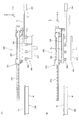
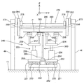
次に第3の実施形態について図28〜図39に基づいて説明する。第3の実施形態に係る液晶露光装置の構成は、ポート部240(図29参照)の構成、及び基板ステージ220の構成が異なる点を除き、上記第1の実施形態と同じであるので、以下、上記第1の実施形態と同様の構成、及び機能を有する要素については、上記第1の実施形態と同じ符号を用いてその説明を省略する。また、図28に示されるように、基板ステージ220の構成は、基板搬出装置70に代えて基板搬出装置270が設けられている点を除き、上記第1の実施形態と同じであるので、以下、相違点についてのみ説明する。
<< Third Embodiment >>
Next, a third embodiment will be described with reference to FIGS. The configuration of the liquid crystal exposure apparatus according to the third embodiment is the same as that of the first embodiment except that the configuration of the port unit 240 (see FIG. 29) and the configuration of the substrate stage 220 are different. Elements having the same configurations and functions as those of the first embodiment are denoted by the same reference numerals as those of the first embodiment, and description thereof is omitted. Further, as shown in FIG. 28, the configuration of the substrate stage 220 is the same as that of the first embodiment except that a substrate carry-out device 270 is provided instead of the substrate carry-out device 70. Only the differences will be described.

ポート部240は、図29に示されるように、基板ステージ220の+X側に配置されており、基板ステージ220とともに不図示のチャンバ内に収容されている。ポート部240は、基板ガイド装置250、及び基板搬入装置260を含む。基板ガイド装置250、及び基板搬入装置260は、床11上に設置された架台242上に搭載されている。   As shown in FIG. 29, the port part 240 is disposed on the + X side of the substrate stage 220 and is housed in a chamber (not shown) together with the substrate stage 220. The port unit 240 includes a substrate guide device 250 and a substrate carry-in device 260. The substrate guide device 250 and the substrate carry-in device 260 are mounted on a gantry 242 installed on the floor 11.

基板ガイド装置250は、液晶露光装置210の外部に設置された外部搬送ロボット298(図29では不図示。図30参照)により液晶露光装置210の内部に搬入された基板P(図29では基板P)が基板搬入装置260により基板ステージ220に搬送される際の中継装置、あるいは基板搬出装置270により搬出された基板ステージ220上の基板P(図29では基板P)が液晶露光装置210の外部に搬出される際の中継装置として機能する。 The substrate guide device 250 is a substrate P (substrate P in FIG. 29) that is carried into the liquid crystal exposure device 210 by an external transfer robot 298 (not shown in FIG. 29; see FIG. 30) installed outside the liquid crystal exposure device 210. 3 ) is transferred to the substrate stage 220 by the substrate carry-in apparatus 260, or the substrate P (the substrate P 1 in FIG. 29) carried out by the substrate carry-out apparatus 270 is transferred to the liquid crystal exposure apparatus 210. Functions as a relay device when being carried outside.

ここで、図30及び図31などに示される外部搬送ロボット298は、例えば米国特許第7,905,699号明細書に開示される外部搬送ロボットと同様に構成されており、アンロードハンド及びロードハンド(図30及び図31では一方は不図示。以下適宜ハンド部材と称する)を有している。アンロードハンド、及びロードハンドそれぞれの構成は、実質的に同じであり、X軸方向に延び、且つY軸方向に離間した複数の薄板状の部材(以下爪部298aと称する)を含み、厚さの薄いフォーク状に形成されている。外部搬送ロボット298は、上記不図示のチャンバの+X側に設置されており、ポート部240に基板Pを搬入(投入)すること、及びポート部240から基板Pを搬出(回収)することができるようになっている。外部搬送ロボット298のアンロードハンド、及びロードハンドそれぞれは、+X側の端部近傍がロボットアーム(不図示)により片持ち支持され、そのロボットアームが適宜制御されることにより、X軸方向に移動する。なお、外部搬送ロボット298としては、基板の搬入(投入)、及び搬出(回収)を一つのフォーク状ハンド部材で行うものを用いても良い。   Here, the external transfer robot 298 shown in FIGS. 30 and 31 is configured in the same manner as the external transfer robot disclosed in, for example, US Pat. No. 7,905,699, and an unload hand and a load It has a hand (one of which is not shown in FIGS. 30 and 31; hereinafter referred to as a hand member as appropriate). Each configuration of the unload hand and the load hand is substantially the same, includes a plurality of thin plate-like members (hereinafter referred to as claw portions 298a) extending in the X-axis direction and spaced in the Y-axis direction. It is formed in a thin fork shape. The external transfer robot 298 is installed on the + X side of the chamber (not shown), and can load (inject) the substrate P into the port unit 240 and can carry out (collect) the substrate P from the port unit 240. It is like that. Each of the unload hand and the load hand of the external transfer robot 298 is cantilevered by a robot arm (not shown) near the end on the + X side, and the robot arm is appropriately controlled to move in the X-axis direction. To do. As the external transfer robot 298, a robot that carries in (in) and out (collects) a substrate with a single fork-shaped hand member may be used.

基板ガイド装置250は、図32に示されるように、Xベース252、Zベース254、Zアクチュエータ256、及び複数のエア浮上装置258などを有している。Xベース252は、XY平面に平行に配置された板状の部材から成る。Xベース252は、架台242の上面に固定されたXリニアガイドとXベース252の下面に固定されたXスライダとから成る複数のXリニアガイド装置251により架台242上でX軸方向に直進案内される。また、Xベース252は、架台242の上面に固定されたX固定子とXベース252の下面に固定されたX可動子とから成るXリニアモータ253により架台242上でX軸方向に駆動される。なお、Xベース252を駆動するアクチュエータの種類は、特に限定されず、例えば送りねじ装置などであっても良い。   As shown in FIG. 32, the substrate guide device 250 includes an X base 252, a Z base 254, a Z actuator 256, a plurality of air levitation devices 258, and the like. The X base 252 is composed of a plate-like member arranged in parallel with the XY plane. The X base 252 is linearly guided in the X-axis direction on the frame 242 by a plurality of X linear guide devices 251 including an X linear guide fixed to the upper surface of the frame 242 and an X slider fixed to the lower surface of the X base 252. The The X base 252 is driven in the X-axis direction on the gantry 242 by an X linear motor 253 composed of an X stator fixed to the upper surface of the gantry 242 and an X mover fixed to the lower surface of the X base 252. . In addition, the kind of actuator which drives the X base 252 is not specifically limited, For example, a feed screw apparatus etc. may be sufficient.

Zベース254は、XY平面に平行に配置された板状の部材から成り、Xベース252上にZアクチュエータ256を介して搭載されている。Zアクチュエータ256は、Zベース254をXベース252上でZ軸方向に駆動する(上下動させる)。Zアクチュエータの種類は、特に限定されないが、Zベース254を、例えば任意の3箇所で停止できることが好ましい。なお、本実施形態では、Zベース254上に搭載された複数のエア浮上装置258をまとめてひとつのZアクチュエータ256により上下動させるが、複数のエア浮上装置258それぞれにZアクチュエータを設けて個別に上下動させても良い。   The Z base 254 is composed of a plate-like member disposed in parallel with the XY plane, and is mounted on the X base 252 via a Z actuator 256. The Z actuator 256 drives the Z base 254 on the X base 252 in the Z-axis direction (moves up and down). The type of the Z actuator is not particularly limited, but it is preferable that the Z base 254 can be stopped at, for example, any three locations. In this embodiment, a plurality of air levitation devices 258 mounted on the Z base 254 are collectively moved up and down by one Z actuator 256, but each of the plurality of air levitation devices 258 is provided with a Z actuator individually. It may be moved up and down.

複数のエア浮上装置258のそれぞれは、Zベース254に支柱257を介して下方から支持されている。本実施形態において、複数のエア浮上装置258は、図31に示されるように、合計で、例えば12台(Y軸方向に所定間隔で配列された3台のエア浮上装置258がX軸方向に所定間隔で4列)設けられているが、基板Pの下面をほぼ均等に支持することが可能であれば(図30及び図32参照)、エア浮上装置258の数及び配列は、例えば基板Pの大きさに応じて適宜変更が可能である。複数のエア浮上装置258のY軸方向に関する間隔は、外部搬送ロボット298のハンド部材(アンロードハンド及びロードハンド)の形状を考慮して決定される。具体的には、外部搬送ロボット298のハンド部材を基板ガイド装置250の上方に位置させた状態で、複数のエア浮上装置258の位置と上記ハンド部材が有する複数の爪部298aのY位置とが重複しないように設定される。   Each of the plurality of air levitation devices 258 is supported from below by the Z base 254 via the support column 257. In this embodiment, as shown in FIG. 31, the plurality of air levitation devices 258 are, for example, 12 units in total (three air levitation devices 258 arranged at predetermined intervals in the Y axis direction in the X axis direction). However, if it is possible to support the lower surface of the substrate P substantially evenly (see FIGS. 30 and 32), the number and arrangement of the air levitation devices 258 may be, for example, the substrate P. Depending on the size, it can be appropriately changed. The intervals of the plurality of air levitation devices 258 in the Y-axis direction are determined in consideration of the shape of the hand member (unload hand and load hand) of the external transfer robot 298. Specifically, with the hand member of the external transfer robot 298 positioned above the substrate guide device 250, the positions of the plurality of air levitation devices 258 and the Y positions of the plurality of claws 298a included in the hand member are as follows. It is set not to overlap.

エア浮上装置258の上面には、複数の孔部が形成されている。エア浮上装置258には、不図示の加圧気体(例えば圧縮空気)供給装置が接続されており、複数のエア浮上装置258上に載置された基板Pの下面に上記複数の孔部から加圧気体を噴出することにより、その基板Pを浮上させることができるようになっている。また、複数のエア浮上装置258の少なくとも一部は、上記複数の孔部(あるいは別の孔部)を用いて基板Pを吸着保持することができるようにもなっている。   A plurality of holes are formed on the upper surface of the air levitation device 258. A pressurized gas (for example, compressed air) supply device (not shown) is connected to the air levitation device 258, and is added to the lower surface of the substrate P placed on the plurality of air levitation devices 258 from the plurality of holes. By ejecting the pressurized gas, the substrate P can be levitated. Further, at least a part of the plurality of air levitation devices 258 can also hold the substrate P by suction using the plurality of holes (or other holes).

基板搬入装置260は、図32に示されるように、基板ガイド装置250に下方から支持された基板Pを基板ステージ220(図32では不図示。図29参照)に搬送する装置であり、架台242上であって、基板ガイド装置250の+Y側に設置されている。基板搬入装置260は、X走行ガイド262、Xスライド部材264、支持部材266、及び吸着パッド268などを有している。なお、図31では、図面の錯綜を避ける観点から基板搬入装置260の図示が省略されている。   As shown in FIG. 32, the substrate carry-in device 260 is a device that transports the substrate P supported by the substrate guide device 250 from below to the substrate stage 220 (not shown in FIG. 32; see FIG. 29). Above, on the + Y side of the substrate guide device 250. The substrate carry-in device 260 includes an X travel guide 262, an X slide member 264, a support member 266, a suction pad 268, and the like. In addition, in FIG. 31, illustration of the board | substrate carrying-in apparatus 260 is abbreviate | omitted from a viewpoint of avoiding complication of drawing.

X走行ガイド262は、X軸方向に延びる部材から成る(図30参照)。Xスライド部材264は、X走行ガイド262に対してX軸方向にスライド可能に係合しており、不図示のXアクチュエータ(例えば送りねじ装置、リニアモータなど)により、X走行ガイド262に沿って所定のストロークで駆動される。支持部材266は、Z軸方向に延びる部材から成り、一端(−Z側の端部)がXスライド部材264に固定されている。支持部材266は、図29に示されるように、長手方向の中間部が曲げて形成されており、他端(+Z側の端部)側が一端側に比べて−X側(基板ステージ220側)に突き出している。   The X travel guide 262 is made of a member extending in the X-axis direction (see FIG. 30). The X slide member 264 is slidably engaged with the X travel guide 262 in the X-axis direction, and along the X travel guide 262 by an X actuator (not shown) (for example, a feed screw device, a linear motor, etc.). It is driven with a predetermined stroke. The support member 266 is made of a member extending in the Z-axis direction, and one end (the end on the −Z side) is fixed to the X slide member 264. As shown in FIG. 29, the support member 266 is formed by bending the middle portion in the longitudinal direction, and the other end (the end portion on the + Z side) side is −X side (substrate stage 220 side) compared to the one end side. Sticks out.

図32に戻り、吸着パッド268は、YZ断面L字状の部材から成り、機械的なZリニアガイド装置269を介して支持部材266の他端(+Z側の端部)部近傍に取り付けられている。吸着パッド268は、支持部材266に取り付けられたZアクチュエータ267(例えばエアシリンダ)により、支持部材266に対してZ軸方向に所定のストロークで駆動される。吸着パッド268は、外部に設置された不図示のバキューム装置に接続されており、上面が基板吸着面部として機能する。   Returning to FIG. 32, the suction pad 268 is made of a member having an L-shaped YZ cross section, and is attached to the vicinity of the other end (+ Z side end) of the support member 266 via a mechanical Z linear guide device 269. Yes. The suction pad 268 is driven with a predetermined stroke in the Z-axis direction with respect to the support member 266 by a Z actuator 267 (for example, an air cylinder) attached to the support member 266. The suction pad 268 is connected to a vacuum device (not shown) installed outside, and the upper surface functions as a substrate suction surface portion.

ここで、基板搬入装置260の動作を図32〜図33(B)を用いて説明する。基板搬入装置260は、図32に示されるように、基板ガイド装置250の複数のエア浮上装置58上に載置された基板Pの下面における+X側かつ+Y側の隅部近傍(図33(A)参照)を吸着パッド268により吸着保持する。そして、図33(A)に示されるように、複数のエア浮上装置258から基板Pの下面に加圧気体が噴出された状態で、吸着パッド268が基板ステージ220側(−X方向)に駆動される。この際、複数のエア浮上装置258の上面のZ位置と基板ホルダ40の上面のZ位置とがほぼ同じに(あるいはエア浮上装置258の方が幾分高く)なるように、複数のエア浮上装置258のZ位置(及び/又は基板ホルダ40のZ位置)が位置決めされる。   Here, the operation of the substrate carry-in device 260 will be described with reference to FIGS. As shown in FIG. 32, the substrate carry-in device 260 is near the corners on the lower surface of the substrate P placed on the plurality of air levitation devices 58 of the substrate guide device 250 on the + X side and the + Y side (FIG. 33A )) Is sucked and held by the suction pad 268. Then, as shown in FIG. 33A, the suction pad 268 is driven to the substrate stage 220 side (−X direction) in a state where the pressurized gas is ejected from the plurality of air levitation devices 258 to the lower surface of the substrate P. Is done. At this time, the plurality of air levitation devices are arranged such that the Z position of the upper surface of the plurality of air levitation devices 258 and the Z position of the upper surface of the substrate holder 40 are substantially the same (or the air levitation device 258 is somewhat higher). The Z position of 258 (and / or the Z position of the substrate holder 40) is positioned.

また、複数のエア浮上装置258を支持するZベース254は、X軸方向に関して最も−X側(基板ステージ220に接近した位置)に位置決めされる。これにより、基板Pが複数のエア浮上装置258の上面と基板ホルダ40の上面(基板載置面)とにより形成されるXY平面にほぼ平行なガイド面に沿ってスライドし、複数のエア浮上装置258上から基板ホルダ40上へと受け渡される。この際、基板ホルダ40の上面からも基板Pの下面に対して加圧気体が噴出される。これにより、基板Pを高速かつ低発塵で基板ガイド装置250上から基板ステージ220上に受け渡すことができる。   In addition, the Z base 254 that supports the plurality of air levitation devices 258 is positioned closest to the −X side (position close to the substrate stage 220) in the X-axis direction. Accordingly, the substrate P slides along a guide surface substantially parallel to the XY plane formed by the upper surfaces of the plurality of air levitation devices 258 and the upper surface (substrate mounting surface) of the substrate holder 40, and the plurality of air levitation devices. It is transferred from 258 to the substrate holder 40. At this time, pressurized gas is also ejected from the upper surface of the substrate holder 40 toward the lower surface of the substrate P. Thereby, the substrate P can be transferred from the substrate guide device 250 onto the substrate stage 220 at high speed and with low dust generation.

また、基板搬入装置260では、吸着パッド268が基板Pの+X側かつ+Y側の隅部近傍を吸着保持することから、図33(A)に示されるように、基板Pが基板ホルダ40上に受け渡される際、基板Pの中心に対して、基板ホルダ40は、その中心が−Y側にずれた位置に位置決めされる。したがって、基板Pは、吸着パッド268に吸着保持される部分を含み、+Y側の端部近傍の領域が基板ホルダ40の+Y側の端部からはみ出して載置される。   Further, in the substrate carry-in device 260, the suction pad 268 sucks and holds the vicinity of the + X side and + Y side corners of the substrate P, so that the substrate P is placed on the substrate holder 40 as shown in FIG. At the time of delivery, the substrate holder 40 is positioned at a position where the center is shifted to the −Y side with respect to the center of the substrate P. Therefore, the substrate P includes a portion that is sucked and held by the suction pad 268, and a region in the vicinity of the + Y side end portion protrudes from the + Y side end portion of the substrate holder 40.

このため、基板ステージ220は、基板ホルダ40上の基板PのY位置を修正するための一対の押圧ピン38a、及び一対の位置決めピン38bを有している。一対の押圧ピン38aは、基板ホルダ40の+Y側にX軸方向に離間して配置され、基板ホルダ40に対してY軸方向に移動可能となっている。一対の位置決めピン38bは、基板ホルダ40を挟んで一対の押圧ピン38aの反対側に配置されている。一対の押圧ピン38a、及び一対の位置決めピン38bは、基板ホルダ40に設けられても良いし、微動ステージ21(図33(A)では不図示。図28参照)、あるいはX粗動ステージ23x(図33(A)では不図示。図28参照)に設けられても良い。また、一対の押圧ピン38a、及び一対の位置決めピン38bの数は、特に限定されない。   For this reason, the substrate stage 220 has a pair of pressing pins 38 a and a pair of positioning pins 38 b for correcting the Y position of the substrate P on the substrate holder 40. The pair of pressing pins 38 a are arranged on the + Y side of the substrate holder 40 so as to be separated from each other in the X axis direction, and are movable in the Y axis direction with respect to the substrate holder 40. The pair of positioning pins 38b is disposed on the opposite side of the pair of pressing pins 38a with the substrate holder 40 interposed therebetween. The pair of pressing pins 38a and the pair of positioning pins 38b may be provided on the substrate holder 40, fine movement stage 21 (not shown in FIG. 33A, see FIG. 28), or X coarse movement stage 23x ( It may be provided in FIG. 33A (not shown in FIG. 28). Further, the number of the pair of pressing pins 38a and the pair of positioning pins 38b is not particularly limited.

基板搬入装置260は、図33(A)に示されるように、基板ホルダ40上に基板Pを搬送すると、吸着パッド268による基板Pの吸着の解除、及び吸着パッド268の−Z方向への駆動を行う。そして、図33(B)に示されるように、吸着パッド268が基板ステージ220から離間する方向(+X方向)に駆動される。また、併せて基板ガイド装置250も、Zベース254を基板ステージ220から離間させる。これにより、基板ステージ220と基板ガイド装置250との間に、例えば作業用のスペースを確保することができる。なお、基板Pと吸着パッド268とを離間させるためには、基板ステージ220の微動ステージ21(図28参照)を+Z方向に駆動しても良く、この場合、基板搬入装置260において、吸着パッド268をZ軸方向に駆動するZアクチュエータ267(図32参照)が不要となる。   As shown in FIG. 33A, when the substrate carry-in device 260 transports the substrate P onto the substrate holder 40, the suction of the substrate P by the suction pad 268 is released, and the suction pad 268 is driven in the −Z direction. I do. Then, as shown in FIG. 33B, the suction pad 268 is driven in a direction away from the substrate stage 220 (+ X direction). In addition, the substrate guide apparatus 250 also separates the Z base 254 from the substrate stage 220. Thereby, for example, a working space can be secured between the substrate stage 220 and the substrate guide device 250. In order to separate the substrate P and the suction pad 268, the fine movement stage 21 (see FIG. 28) of the substrate stage 220 may be driven in the + Z direction. In this case, the suction pad 268 is used in the substrate carry-in device 260. Z actuator 267 (refer to FIG. 32) for driving in the Z-axis direction becomes unnecessary.

また、基板ステージ220では、一対の押圧ピン38aが基板Pの+Y側の端部を押圧し、基板Pの中心と基板ホルダ40の中心とがほぼ一致する位置まで基板Pを−Y方向に所定距離(例えば10〜100mm程度)移動させる。この後、基板ホルダ40は、基板Pを吸着保持する。なお、基板ホルダ40上における基板PのX軸方向の位置決めを行うための押圧ピン、及び位置決めピンを基板ホルダ40の+X側及び−X側にそれぞれ設けても良い。   In the substrate stage 220, the pair of pressing pins 38a presses the + Y side end of the substrate P, and the substrate P is predetermined in the −Y direction until the center of the substrate P substantially coincides with the center of the substrate holder 40. Move the distance (for example, about 10 to 100 mm). Thereafter, the substrate holder 40 holds the substrate P by suction. A pressing pin for positioning the substrate P in the X-axis direction on the substrate holder 40 and a positioning pin may be provided on the + X side and the −X side of the substrate holder 40, respectively.

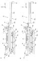
図30に戻り、基板搬出装置270は、一対のX走行ガイド272、懸垂保持装置280、落下防止装置290などを有している。   Returning to FIG. 30, the substrate carry-out device 270 includes a pair of X travel guides 272, a suspension holding device 280, a fall prevention device 290, and the like.

一対のX走行ガイド272は、それぞれX軸方向に延びる部材から成り、Y軸方向に所定間隔(基板PのY軸方向寸法よりも広い間隔)で互いに平行に配置されている。各X走行ガイド272の長手方向寸法は、基板PのX軸方向寸法の2倍よりも長く(例えば2.5倍程度に)設定されている。各X走行ガイド272は、図32に示されるように、床11上に設置された複数の支柱44により下方から支持されている。複数の支柱44は、各X走行ガイド272の長手方向の両端部近傍及び中央部を支持している。なお、図28及び図32から分かるように、複数の支柱44のうち、一対のX走行ガイド272の−X側の端部近傍を支持する一対の支柱44(図28参照)は、基板ステージ220との干渉を避けるため、他の支柱44(図32参照)に比べて、幾分Y軸方向に関して離して配置されている。なお、一対のX走行ガイド272は、例えば吊り下げ支持されていても良い。また、図29では図面の錯綜を避ける観点から支柱44の図示が省略されている。   The pair of X travel guides 272 are each composed of a member extending in the X-axis direction, and are arranged in parallel to each other at a predetermined interval in the Y-axis direction (interval wider than the dimension in the Y-axis direction of the substrate P). The longitudinal dimension of each X traveling guide 272 is set to be longer (for example, about 2.5 times) than twice the dimension of the substrate P in the X-axis direction. As shown in FIG. 32, each X traveling guide 272 is supported from below by a plurality of columns 44 installed on the floor 11. The plurality of columns 44 support the vicinity of the both ends in the longitudinal direction and the center of each X traveling guide 272. As can be seen from FIG. 28 and FIG. 32, of the plurality of columns 44, the pair of columns 44 (see FIG. 28) that supports the vicinity of the ends on the −X side of the pair of X traveling guides 272 is the substrate stage 220. In order to avoid interference with the other columns 44, they are arranged somewhat apart from each other in the Y-axis direction as compared with other columns 44 (see FIG. 32). Note that the pair of X traveling guides 272 may be supported by hanging, for example. Also, in FIG. 29, the support 44 is not shown from the viewpoint of avoiding the complexity of the drawing.

図30に戻り、一対のX走行ガイド272それぞれには、X軸方向に離間した、例えば2つのXスライド部材274が機械的に係合している。すなわち、基板搬出装置270全体でXスライド部材274は、例えば合計4つ設けられている。例えば合計4つのXスライド部材274は、対応するX走行ガイド272に対してX軸方向にスライド可能に係合しており、不図示のXアクチュエータ(例えば送りねじ装置、リニアモータ、ベルト駆動装置など)により、対応するX走行ガイド272に沿って同期駆動される。   Returning to FIG. 30, for example, two X slide members 274 separated in the X-axis direction are mechanically engaged with each of the pair of X traveling guides 272. That is, a total of four X slide members 274 are provided in the entire substrate carry-out device 270, for example. For example, a total of four X slide members 274 are engaged with corresponding X travel guides 272 so as to be slidable in the X-axis direction, and an X actuator (not shown) (for example, a feed screw device, a linear motor, a belt drive device, etc.) ) Is driven synchronously along the corresponding X travel guide 272.

図29に示されるように、一方のX走行ガイド272(図29では+Y側であるが−Y側のX走行ガイド272についても同様。以下同じ)に係合する、例えば2つのXスライド部材274には、それぞれZ走行ガイド276が固定されている。すなわち、図30に示されるように、基板搬出装置270全体でZ走行ガイド276は、例えば合計4つ設けられている。図29に戻り、Z走行ガイド276は、Z軸方向に延びる部材から成り、+Z側の端部近傍がXスライド部材274に接続されている。したがって、Z走行ガイド276の−Z側の端部は、X走行ガイド272よりも下方(−Z側)に突き出している。   As shown in FIG. 29, for example, two X slide members 274 that engage with one X travel guide 272 (in FIG. 29, the same applies to the −Y side X travel guide 272 but the same applies to the −Y side). A Z travel guide 276 is fixed to each of the two. That is, as shown in FIG. 30, a total of four Z travel guides 276 are provided in the entire substrate carry-out device 270, for example. Returning to FIG. 29, the Z travel guide 276 is formed of a member extending in the Z-axis direction, and the vicinity of the + Z side end is connected to the X slide member 274. Therefore, the −Z side end of the Z travel guide 276 protrudes downward (−Z side) from the X travel guide 272.

図30に示されるように、例えば4つのZ走行ガイド276には、それぞれZスライド部材278が機械的に係合している。すなわち、基板搬出装置270全体でZスライド部材278は、例えば合計4つ設けられている。例えば合計4つのZスライド部材278は、対応するZ走行ガイド276に対してZ軸方向にスライド可能に係合しており、不図示のZアクチュエータ(例えば送りねじ装置、リニアモータ、ベルト駆動装置など)により、Z走行ガイド276に沿って同期駆動される。   As shown in FIG. 30, for example, Z slide members 278 are mechanically engaged with four Z travel guides 276, respectively. That is, a total of four Z slide members 278 are provided in the entire substrate carry-out device 270, for example. For example, a total of four Z slide members 278 are engaged with corresponding Z travel guides 276 so as to be slidable in the Z axis direction, and Z actuators (not shown) (for example, a feed screw device, a linear motor, a belt drive device, etc.) ) To drive synchronously along the Z travel guide 276.

また、図29に示されるように、一方のX走行ガイド272には、例えば2つのXスライド部材274の+X側にXスライド部材292が機械的に係合している。すなわち、図30に示されるように、基板搬出装置270全体でXスライド部材292は、例えば合計2つ設けられている。例えば合計2つのXスライド部材292は、対応するX走行ガイド272に対してX軸方向にスライド可能に係合しており、不図示のXアクチュエータ(例えば送りねじ装置、リニアモータ、ベルト駆動装置など)により、対応するX走行ガイド272に沿って同期駆動される。   As shown in FIG. 29, for example, an X slide member 292 is mechanically engaged with one X travel guide 272 on the + X side of two X slide members 274, for example. That is, as shown in FIG. 30, a total of two X slide members 292 are provided in the entire substrate carry-out device 270, for example. For example, a total of two X slide members 292 are slidably engaged with the corresponding X travel guide 272 in the X axis direction, and an X actuator (not shown) (for example, a feed screw device, a linear motor, a belt drive device, etc.) ) Is driven synchronously along the corresponding X travel guide 272.

ここで、例えば2つのXスライド部材292と、上記例えば4つのXスライド部材274とは、X軸方向に関して独立して位置制御を行うことができるようになっている。Xスライド部材274、及びXスライド部材292を駆動するXアクチュエータがリニアモータである場合、Xスライド部材274を駆動するためのXリニアモータのX固定子(例えば磁石ユニット)と、Xスライド部材292を駆動するためのXリニアモータのX固定子とは、共通であっても良い。   Here, for example, the two X slide members 292 and the four X slide members 274, for example, can perform position control independently in the X-axis direction. When the X slide member 274 and the X actuator that drives the X slide member 292 are linear motors, an X stator (for example, a magnet unit) of the X linear motor for driving the X slide member 274 and an X slide member 292 are provided. The X stator of the X linear motor for driving may be common.

2つのXスライド部材292のそれぞれには、図29に示されるように、Z走行ガイド294が固定されている。Z走行ガイド294は、Z軸方向に延びる部材から成り、+Z側の端部近傍がXスライド部材292に接続されている。したがって、Z走行ガイド294の−Z側の端部は、X走行ガイド272よりも下方(−Z側)に突き出している。ここで、Z走行ガイド294の長手方向の寸法は、上記Z走行ガイド276よりも長く設定されている。Z走行ガイド294には、Zスライド部材296が機械的に係合している。すなわち、図30に示されるように、基板搬出装置270全体でZスライド部材296は、例えば合計2つ設けられている。例えば合計2つのZスライド部材296は、対応するZ走行ガイド294に対してZ軸方向にスライド可能に係合しており、不図示のZアクチュエータ(例えば送りねじ装置、リニアモータ、ベルト駆動装置など)により、対応するZ走行ガイド294に沿って同期駆動される。   As shown in FIG. 29, a Z travel guide 294 is fixed to each of the two X slide members 292. The Z travel guide 294 is composed of a member extending in the Z-axis direction, and the vicinity of the + Z side end is connected to the X slide member 292. Therefore, the −Z side end of the Z travel guide 294 protrudes downward (−Z side) from the X travel guide 272. Here, the longitudinal dimension of the Z travel guide 294 is set longer than that of the Z travel guide 276. A Z slide member 296 is mechanically engaged with the Z travel guide 294. That is, as shown in FIG. 30, a total of two Z slide members 296 are provided in the entire substrate carry-out device 270, for example. For example, a total of two Z slide members 296 are engaged with corresponding Z travel guides 294 so as to be slidable in the Z-axis direction, and a Z actuator (not shown) (for example, a feed screw device, a linear motor, a belt drive device, etc.) ) Is driven synchronously along the corresponding Z travel guide 294.

懸垂保持装置280は、図30に示されるように、平面視矩形の高さの低い直方体状の箱型部材から成り、四隅部近傍に上述した例えば4つのZスライド部材278それぞれが接続されている。したがって、例えば4つのXスライド部材274が対応するX走行ガイド272に沿ってX軸方向に同期駆動されることにより、懸垂保持装置280がX軸方向に移動する。また、懸垂保持装置280は、例えば4つのZスライド部材278が対応するZ走行ガイド276に沿ってZ軸方向に同期駆動されることにより、Z軸方向に移動する。なお、懸垂保持装置280をX軸、及びZ軸方向に駆動可能であれば、Z走行ガイド276、Zスライド部材278の配置及び数は、適宜変更が可能であり、懸垂保持装置280の撓みを抑制するために、本実施形態より多く設けられても良い。   As shown in FIG. 30, the suspension holding device 280 is formed of a rectangular parallelepiped box-shaped member having a rectangular shape in plan view, and each of the four Z slide members 278 described above is connected in the vicinity of the four corners. . Therefore, for example, when the four X slide members 274 are synchronously driven in the X axis direction along the corresponding X travel guides 272, the suspension holding device 280 moves in the X axis direction. Further, the suspension holding device 280 moves in the Z-axis direction by, for example, four Z slide members 278 being synchronously driven in the Z-axis direction along the corresponding Z travel guides 276. If the suspension holding device 280 can be driven in the X-axis and Z-axis directions, the arrangement and number of the Z traveling guide 276 and the Z slide member 278 can be changed as appropriate, and the suspension holding device 280 can be bent. In order to suppress, more than this embodiment may be provided.

懸垂保持装置280は、複数の非接触チャック装置282を有している。非接触チャック装置282は、ベルヌーイチャックなどとも称され、その構成は、例えば米国特許第5,067,762号明細書などに開示されている。すなわち、複数の非接触チャック装置282それぞれには、不図示の気体供給装置が接続されており、懸垂保持装置280の下面と基板Pの上面とが所定の隙間(ギャップ、クリアランス)を介して対向した状態で、複数の非接触チャック装置282それぞれは、基板Pの上面に対して加圧気体(例えば空気)を高速で噴出する。そして、懸垂保持装置280の下面と基板Pの上面との間を高速で通過する気体の作用(いわゆるベルヌーイ効果、及びエゼクタ効果)により、基板Pに重量方向上向きの力(吸引力)が作用し、基板Pが懸垂保持装置280に非接触保持(吸引保持)される。ここで、懸垂保持装置280は、基板Pの表面(上面、露光面)に対して気体を噴出するが、本実施形態において、懸垂保持装置280に保持される基板Pは、露光済みであるので、仮に上記加圧気体に塵埃が含まれていたとしても露光不良となるおそれがない。   The suspension holding device 280 has a plurality of non-contact chuck devices 282. The non-contact chuck device 282 is also called a Bernoulli chuck or the like, and its configuration is disclosed in, for example, US Pat. No. 5,067,762. That is, a gas supply device (not shown) is connected to each of the plurality of non-contact chuck devices 282, and the lower surface of the suspension holding device 280 and the upper surface of the substrate P are opposed to each other with a predetermined gap (gap, clearance). In this state, each of the plurality of non-contact chuck devices 282 ejects pressurized gas (for example, air) at high speed onto the upper surface of the substrate P. Then, an upward force (attraction force) in the weight direction acts on the substrate P by the action of gas (so-called Bernoulli effect and ejector effect) that passes between the lower surface of the suspension holding device 280 and the upper surface of the substrate P at high speed. The substrate P is non-contact-held (suction-held) by the suspension holding device 280. Here, the suspension holding device 280 ejects gas to the surface (upper surface, exposure surface) of the substrate P. However, in this embodiment, the substrate P held by the suspension holding device 280 has already been exposed. Even if dust is contained in the pressurized gas, there is no risk of exposure failure.

そして、基板Pを非接触保持した状態で、懸垂保持装置280がX軸方向、あるいはZ軸方向に駆動されることにより、基板Pがその懸垂保持装置280と一体的にX軸方向、あるいはZ軸方向に移動する。これにより、基板ガイド装置250の上方と、所定の基板交換位置に位置した基板ホルダ40(図29参照)の上方との間で基板PをX軸方向に搬送することができるとともに、基板ガイド装置250の上方、及び基板交換位置に位置した基板ホルダ40の上方それぞれの位置で基板Pを上下動させることができる。なお、本実施形態では、基板Pの全体に均等に吸引力を作用させることができるように、例えば25台の非接触チャック装置282がX軸方向、及びY軸方向に所定の間隔で配置されているが、非接触チャック装置282の数、及び配置は、これに限られず、例えば基板Pの大きさなどに応じて適宜変更が可能である。   Then, the suspension holding device 280 is driven in the X-axis direction or the Z-axis direction while holding the substrate P in a non-contact manner, so that the substrate P is integrated with the suspension holding device 280 in the X-axis direction or Z-direction. Move in the axial direction. Accordingly, the substrate P can be transported in the X-axis direction between the upper side of the substrate guide device 250 and the upper side of the substrate holder 40 (see FIG. 29) positioned at a predetermined substrate replacement position. The substrate P can be moved up and down at positions above 250 and above the substrate holder 40 located at the substrate replacement position. In the present embodiment, for example, 25 non-contact chuck devices 282 are arranged at predetermined intervals in the X-axis direction and the Y-axis direction so that the suction force can be applied uniformly to the entire substrate P. However, the number and arrangement of the non-contact chuck devices 282 are not limited to this, and can be appropriately changed according to the size of the substrate P, for example.

ここで、非接触チャック装置282が基板Pの水平面内の位置を拘束しないので、懸垂保持装置280は、基板Pを搬送する際にその基板Pと懸垂保持装置280とがX軸、Y軸、及びθz方向に相対移動しないようにするために、下面における+X側及び−X側の端部近傍それぞれに、図29に示されるように、複数(図29では紙面奥行き方向に重なっている)の押し当てピン281を有している。複数の押し当てピン281それぞれは、X軸方向に所定のストロークで移動可能とされ、基板Pの+X側の端部、あるいは基板Pの−X側の端部に当接することにより、その基板Pと懸垂保持装置280とのX軸方向の相対移動を抑制する。また、懸垂保持装置280には、不図示であるが、基板Pの+Y側の端部、あるいは基板Pの−Y側の端部に当接することにより、上記基板Pと懸垂保持装置280とのY軸方向の相対移動を抑制する押し当てピンも設けられている。なお、複数の押し当てピン281は、X軸方向に移動しない構成でも構わない。   Here, since the non-contact chuck device 282 does not restrain the position of the substrate P in the horizontal plane, the suspension holding device 280 is configured such that when the substrate P is transported, the substrate P and the suspension holding device 280 have the X axis, the Y axis, In order to prevent relative movement in the θz direction, as shown in FIG. 29, a plurality of (in FIG. 29, overlap in the depth direction of the paper surface) are provided near the + X side and −X side end portions on the lower surface. A pressing pin 281 is provided. Each of the plurality of pressing pins 281 is movable with a predetermined stroke in the X-axis direction, and comes into contact with the end of the substrate P on the + X side or the end of the substrate P on the −X side. And the relative movement of the suspension holding device 280 in the X-axis direction are suppressed. Although not shown, the suspension holding device 280 contacts the + Y side end of the substrate P or the −Y side end of the substrate P, so that the substrate P and the suspension holding device 280 are connected to each other. A pressing pin that suppresses relative movement in the Y-axis direction is also provided. The plurality of pressing pins 281 may be configured not to move in the X-axis direction.

落下防止装置290は、懸垂保持装置280による基板Pの搬送動作を支援する装置であり、具体的には、基板搬出装置270が懸垂保持装置280を用いて基板Pを搬送する際に、例えば複数の非接触チャック装置282の一部(あるいは全部)に対する気体の供給が停止するなどして懸垂保持装置280の基板保持機能が低下(あるいは無効化)した場合に、基板Pが床11、あるいは基板ステージ220等(図29参照)の上に落下するのを防止するために設けられている。   The fall prevention device 290 is a device that supports the transport operation of the substrate P by the suspension holding device 280. Specifically, when the substrate carry-out device 270 transports the substrate P using the suspension holding device 280, for example, a plurality of fall prevention devices 290 are provided. When the substrate holding function of the suspension holding device 280 is lowered (or invalidated) due to the gas supply to a part (or all) of the non-contact chuck device 282 being stopped, the substrate P is placed on the floor 11 or the substrate. It is provided to prevent falling on the stage 220 or the like (see FIG. 29).

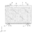
落下防止装置290は、図31に示されるように、一対の本体部290a、該一対の本体部290aを互いに接続する接続部290b、290c、及び一対の本体部290a間に架設された複数の架設部290dを備えている。一対の本体部290aは、それぞれX軸方向に延びる棒状に形成され、Y軸方向に所定の間隔(本実施形態では、基板PのY軸方向寸法よりも幾分広い間隔)で互いに平行に配置されている。本体部290aのX軸方向(長手方向)寸法は、基板PのX軸方向の寸法と同程度に設定されている。   As shown in FIG. 31, the fall prevention device 290 includes a pair of main body portions 290a, connecting portions 290b and 290c that connect the pair of main body portions 290a to each other, and a plurality of bridges laid between the pair of main body portions 290a. 290d is provided. The pair of main body portions 290a are each formed in a rod shape extending in the X-axis direction, and are arranged in parallel with each other at a predetermined interval in the Y-axis direction (in this embodiment, an interval somewhat larger than the dimension in the Y-axis direction of the substrate P). Has been. The X-axis direction (longitudinal direction) dimension of the main body 290a is set to be approximately the same as the dimension of the substrate P in the X-axis direction.

接続部290b、290cは、それぞれY軸方向に延びる部材から成り、接続部290bは、一対の本体部290aの+X側の端部近傍を、接続部290cは、一対の本体部290aの−X側の端部近傍を、それぞれ互いに接続している。架設部290dは、Y軸方向に延びる棒状に形成され、本実施形態では、X軸方向に所定間隔で、例えば7本設けられている。複数の架設部290dは、一対の本体部290a間に所定の張力が与えられた(撓みが抑制された)状態で架設されている。架設部290dとしては、金属材料、あるいはCFRP(Carbon Fiber Reinforced Plastics)により形成された棒材の部材、あるいはワイヤーロープや合成樹脂ロープなどが用いられている。   The connecting portions 290b and 290c are each made of a member extending in the Y-axis direction, the connecting portion 290b is near the end on the + X side of the pair of main body portions 290a, and the connecting portion 290c is the −X side of the pair of main body portions 290a. The vicinity of the end portions of the two are connected to each other. The erection part 290d is formed in a rod shape extending in the Y-axis direction, and in the present embodiment, for example, seven are provided at predetermined intervals in the X-axis direction. The plurality of installation parts 290d are installed in a state where a predetermined tension is applied between the pair of main body parts 290a (bending is suppressed). As the erection portion 290d, a metal material, a bar member formed of CFRP (Carbon Fiber Reinforced Plastics), a wire rope, a synthetic resin rope, or the like is used.

接続部290bは、上述した例えば2つのZスライド部材296間に架設されており、落下防止装置290は、例えば2つのZスライド部材296と一体的にX軸方向、あるいはZ軸方向に移動可能となっている。ここで、図29に示されるように、懸垂保持装置280用のZ走行ガイド276に比べ、落下防止装置290用のZ走行ガイド294の方が長く形成されていることから、落下防止装置290のZ位置は、懸垂保持装置280よりも下方となっている。そして、落下防止装置290と懸垂保持装置280とがX軸方向に相対的に駆動されることにより、落下防止装置290は、図29に示されるような、懸垂保持装置280に対して上下方向に重なる位置(懸垂保持装置280の下方の位置)と、図31に示されるような、X軸方向に関して懸垂保持装置280と上下方向に重ならない位置との間を移動することができるようになっている(図30は、落下防止装置290の−X側の半分程度が懸垂保持装置280の下方に位置した状態を示している)。   The connecting portion 290b is provided between, for example, the two Z slide members 296 described above, and the fall prevention device 290 can be moved integrally with the two Z slide members 296 in the X axis direction or the Z axis direction, for example. It has become. Here, as shown in FIG. 29, the Z travel guide 294 for the fall prevention device 290 is formed longer than the Z travel guide 276 for the suspension holding device 280. The Z position is below the suspension holding device 280. Then, the fall prevention device 290 and the suspension holding device 280 are relatively driven in the X-axis direction, so that the fall prevention device 290 is vertically moved with respect to the suspension holding device 280 as shown in FIG. It is possible to move between an overlapping position (a position below the suspension holding device 280) and a position that does not overlap the suspension holding device 280 with respect to the X-axis direction as shown in FIG. (FIG. 30 shows a state in which about half of the −X side of the fall prevention device 290 is positioned below the suspension holding device 280).

また、例えば7本の架設部290d相互間の間隔、及び最も−X側の架設部290dと接続部290cとの間隔は、基板ガイド装置250が有するエア浮上装置258のX軸方向の寸法よりも長く、かつ図31に示される基板ガイド装置250の上方に落下防止装置290を位置させた状態で、上記複数のエア浮上装置258のX位置と複数の架設部290dのX位置とが重複しないように設定されている。したがって、図31に示される状態で、複数のエア浮上装置258を上下動させると、該複数のエア浮上装置258は、互いに隣接する架設部290dの間、あるいは最も−X側の架設部290dと接続部290cとの間を通過する。なお、複数のエア浮上装置258が互いに隣接する架設部290dの間を通過できれば、複数の架設部290dの数、及び向きは、適宜変更可能であり、例えばX軸方向に延びていても良い。   Further, for example, the distance between the seven erection parts 290d and the distance between the erection part 290d and the connection part 290c on the most −X side are larger than the dimension in the X-axis direction of the air levitation device 258 included in the substrate guide device 250. The X position of the plurality of air levitation devices 258 and the X position of the plurality of installation portions 290d do not overlap with each other when the fall prevention device 290 is positioned above the substrate guide device 250 shown in FIG. Is set to Therefore, when the plurality of air levitation devices 258 are moved up and down in the state shown in FIG. 31, the plurality of air levitation devices 258 are arranged between the erection portions 290d adjacent to each other or the most −X side erection portion 290d. It passes between the connection part 290c. As long as the plurality of air levitation devices 258 can pass between the adjacent erection parts 290d, the number and direction of the erection parts 290d can be changed as appropriate, and may extend in the X-axis direction, for example.

以下、液晶露光装置210における基板ホルダ40上の基板P(便宜上、複数の基板Pを基板P、基板P、基板Pとする)の交換動作について図34(A)〜図39(B)を用いて説明する。以下の基板交換動作は、不図示の主制御装置の管理の下に行われる。なお、図面の簡略化のため、図34(A)〜図39(B)では、基板ステージ220の基板ホルダ40以外の部材、基板ガイド装置250のZアクチュエータ256及びXベース252(それぞれ図32参照)、及び基板搬入装置260(図32参照)の図示がそれぞれ省略されている。 Hereinafter, the exchange operation of the substrate P on the substrate holder 40 in the liquid crystal exposure apparatus 210 (for convenience, a plurality of substrates P will be referred to as substrate P 1 , substrate P 2 , and substrate P 3 ) will be described with reference to FIGS. ). The following board replacement operation is performed under the control of a main controller (not shown). For simplification of the drawings, in FIGS. 34A to 39B, members other than the substrate holder 40 of the substrate stage 220, the Z actuator 256 and the X base 252 of the substrate guide apparatus 250 (see FIG. 32 respectively). ) And the substrate carry-in device 260 (see FIG. 32) are omitted.

図34(A)には、基板ホルダ40に保持された基板Pに対して露光動作が行われている状態が示されている。基板ガイド装置250上には、基板Pの次に露光動作が行われる予定の別の基板Pが載置されている。基板搬出装置270では、基板Pに対して露光動作が行われている最中に、懸垂保持装置280が基板交換位置の上方に位置するように−X方向に駆動される。この際、落下防止装置290は、基板ガイド装置250の上方の位置に待機している。 Figure 34 (A) is, the exposure operation with respect to the substrate P 1 which is held by the substrate holder 40 is shown the state being performed. On the substrate guide device 250, another substrate P 2 are placed that will next exposure operation of the substrate P 1 is carried out. In the substrate carry-out device 270, during the exposure operation on substrate P 1 is being performed, suspending the holding device 280 is driven in the -X direction so as to be positioned above the substrate exchange position. At this time, the fall prevention device 290 stands by at a position above the substrate guide device 250.

基板Pに対する露光動作が終了すると、基板ステージ220では、図34(B)に矢印で示されるように、基板Pが所定の基板交換位置に位置するように基板ホルダ40が位置制御される。さらに、基板搬出装置270では、予め基板交換位置の上方に待機していた懸垂保持装置280が基板ホルダ40に接近する方向(下方)に駆動される。 When the exposure operation for the substrate P 1 is completed, the substrate stage 220, as indicated by the arrows, the substrate holder 40 so that the substrate P 1 is positioned to a predetermined substrate exchange position is the position control in FIG. 34 (B) . Further, in the substrate carry-out device 270, the suspension holding device 280 that has been waiting in advance above the substrate replacement position is driven in a direction (downward) approaching the substrate holder 40.

基板Pが基板交換位置に位置決めされると、図35(A)に矢印で示されるように、懸垂保持装置280は、更に下方に駆動され、基板Pの上面と懸垂保持装置280の下面との距離が所定値(上記非接触チャック装置282(図35(A)では不図示。図30参照)による基板保持機能が発揮される距離)となるように位置決めされる。また、懸垂保持装置280の下面から突き出した押し当てピン281が基板Pに当接するまで駆動される。 When the substrate P 1 is positioned at the substrate replacement position, as shown by an arrow in FIG. 35A, the suspension holding device 280 is further driven downward, and the upper surface of the substrate P 1 and the lower surface of the suspension holding device 280 are moved. Is a predetermined value (a distance at which the substrate holding function is exhibited by the non-contact chuck device 282 (not shown in FIG. 35A, see FIG. 30)). Also, pressing pin 281 that protrudes from the lower surface of the suspension holding device 280 is driven until it abuts against the substrate P 1.

この後、図35(B)に示されるように、懸垂保持装置280から懸垂保持装置280の下面と基板Pの上面と間に気体が高速で噴出され、これにより基板Pが懸垂保持装置280に非接触で懸垂保持される(図35(B)の白矢印は、空気の流れの向きではなく力の向きを示す)。そして、基板ホルダ40による基板Pの吸着保持が解除されるとともに、懸垂保持装置280が上昇駆動されることにより、基板Pの下面が基板ホルダ40の上面から離間する。また、基板ガイド装置250では、複数のエア浮上装置258から基板Pの下面に対して加圧気体が噴出され、これにより基板Pが複数のエア浮上装置258上に浮上する。また、基板ステージ220では、基板Pの搬入に備えて基板ホルダ40の上面から加圧気体が噴出される。 Thereafter, as shown in FIG. 35 (B), the gas between the lower surface and the upper surface of the substrate P 1 of the suspension holding device 280 from the suspension holding device 280 is ejected at high speed, thereby the substrate P 1 is suspended holding device 280 is suspended in a non-contact manner (the white arrow in FIG. 35B indicates the direction of force, not the direction of air flow). Then, the suction and holding of the substrate P 1 by the substrate holder 40 is released, and the suspension holding device 280 is driven upward, so that the lower surface of the substrate P 1 is separated from the upper surface of the substrate holder 40. Further, the substrate guide device 250, pressurized gas from a plurality of air floating device 258 to the lower surface of the substrate P 2 is ejected, thereby the substrate P 2 is floated over a plurality of air floating device 258. In addition, in the substrate stage 220, pressurized gas is ejected from the upper surface of the substrate holder 40 in preparation for loading the substrate P 2 .

基板Pの下面が基板ホルダ40の上面から離間すると、図36(A)に矢印で示されるように、落下防止装置290が−X方向に駆動され、基板Pの下面と基板ホルダ40の上面との間に挿入される。また、基板ホルダ40上には、基板搬入装置260(図36(A)では不図示。図32参照)により、基板Pが搬送される(基板搬入装置260による基板搬入動作は図33(A)及び図33(B)参照)。すなわち、落下防止装置290を基板Pと基板ホルダ40との間に挿入する動作と、基板搬入装置260による基板ホルダ40への基板Pの搬入動作とが並行して行われる。 When the lower surface of the substrate P 1 is separated from the upper surface of the substrate holder 40, the fall prevention device 290 is driven in the −X direction as indicated by an arrow in FIG. 36A, and the lower surface of the substrate P 1 and the substrate holder 40 are It is inserted between the upper surface. In addition, over the substrate holder 40, the substrate carry-in device 260 (see FIG. 36 (A) not shown. Figure 32), the substrate carry operation by (substrate carry-in device 260 in which the substrate P 2 is conveyed FIG 33 (A ) And FIG. 33 (B)). That is, an operation for inserting, and carrying operation of the substrate P 2 to the substrate holder 40 by the substrate carry-in device 260 are performed in parallel between the fall prevention device 290 of the substrate P 1 and the substrate holder 40.

基板ホルダ40への基板Pの搬入後(搬入完了前でも良い)、基板搬出装置270では、図36(B)に示されるように、懸垂保持装置280と落下防止装置290とが一体的に(落下防止装置290が懸垂保持装置280に追従して)+X方向に駆動される。これにより、基板Pが基板ステージ220上から搬出される。この際、上述したように、仮に非接触チャック装置282(図36(B)では不図示。図30参照)に対する気体の供給が停止するなどして懸垂保持装置280の基板保持機能が無効化したとしても、基板Pは、予め基板Pの下方に配置された落下防止装置290上に落下するので床11、あるいは基板ステージ220等(図29参照)の上に落下するのが防止される。また、これと併せて基板ガイド装置250が基板ステージ220から離間する方向(+X方向)に駆動される。 After loading of the substrate P 2 to the substrate holder 40 (or a front loading completed), the substrate carry-out device 270, as shown in FIG. 36 (B), a suspension holding device 280 and the drop prevention device 290 is integrally The fall prevention device 290 is driven in the + X direction (following the suspension holding device 280). As a result, the substrate P 1 is unloaded from the substrate stage 220. At this time, as described above, the substrate holding function of the suspension holding device 280 is invalidated by temporarily stopping the supply of gas to the non-contact chuck device 282 (not shown in FIG. 36B, see FIG. 30). as well, the substrate P 1 is prevented from falling onto the previously because falls onto the anti-fall device 290 disposed below the substrate P 1 bed 11, or the substrate stage 220 and the like (see FIG. 29) . At the same time, the substrate guide device 250 is driven in a direction away from the substrate stage 220 (+ X direction).

基板Pが基板ホルダ40上に載置された基板ステージ220は、基板Pを基板ホルダ40に吸着保持させるとともに、図37(A)に矢印で示されるように、該基板Pに対する露光動作のために基板ホルダ40を基板交換位置から所定の露光動作開始位置(例えばアライメント検出系の下方の位置)に移動させる。なお、図37(B)〜図39(B)には、基板Pを保持した基板ステージ220が便宜上図示されているが、以下説明するポート部240における基板Pと基板Pとの交換動作と基板Pの露光動作とは、並行して行われ、基板ステージ220の実際の位置は異なる。 A substrate stage 220 which the substrate P 2 is placed on the substrate holder 40, the substrate P 2 together is attracted and held by the substrate holder 40, as indicated by the arrows in FIG. 37 (A), exposure of the substrate P 2 For the operation, the substrate holder 40 is moved from the substrate replacement position to a predetermined exposure operation start position (for example, a position below the alignment detection system). Note that the exchange of Although the substrate stage 220 which holds the substrate P 2 is illustrated for convenience, and the substrate P 1 and the substrate P 3 at the port unit 240 to be described below FIG. 37 (B) ~ Figure 39 (B) operation and the exposure operation of the substrate P 2, performed in parallel, the actual position of the substrate stage 220 is different.

また、基板Pが懸垂保持装置280により基板ガイド装置250の上方に搬送されると、図37(A)に矢印で示されるように、基板ガイド装置250の複数のエア浮上装置258が上昇駆動されるとともに、基板搬出装置270の落下防止装置290が下降駆動される。複数のエア浮上装置258は、落下防止装置290の複数の架設部290dの間を通過し、基板Pを下方から支持する。懸垂保持装置280は、基板Pが複数のエア浮上装置258に下方から支持された後、非接触チャック装置282(図37(A)では不図示。図30参照)からの気体の噴出を停止する。これにより、懸垂保持装置280による基板Pの懸垂保持が解除され、この後、懸垂保持装置280は、複数の押し当てピン281それぞれが基板Pから離間する方向に駆動されると共に、上昇駆動される。 Further, when the substrate P 1 is conveyed by the suspension holder 280 above the substrate guide device 250, as indicated by the arrows in FIG. 37 (A), a plurality of air floating devices 258 of the substrate guide device 250 is driven upward At the same time, the fall prevention device 290 of the substrate carry-out device 270 is driven downward. A plurality of air floating device 258 passes between the plurality of bridging portions 290d of the fall prevention device 290 supports the substrate P 1 from below. Suspension holding device 280, after the substrate P 1 is supported from below into a plurality of air floating device 258, stops the ejection of gas from the non-contact chuck device 282 (see FIG. 37 (A) not shown. Figure 30) To do. As a result, the suspension holding of the substrate P by the suspension holding device 280 is released, and thereafter, the suspension holding device 280 is driven in a direction in which each of the plurality of pressing pins 281 is separated from the substrate P 1 and is driven upward. The

次いで、基板Pを液晶露光装置210(図28参照)の外部に搬出するために、図37(B)に矢印で示されるように、外部搬送ロボット298のハンド部材が落下防止装置290の下降駆動により形成された基板Pの下方のスペースに挿入される。この際、上述したように外部搬送ロボット298のハンド部材と複数のエア浮上装置258とは、接触しない。この後、図38(A)に矢印で示されるように、外部搬送ロボット298のハンド部材が上昇駆動されることにより、基板Pが該ハンド部材に下方から支持され(複数の基板ガイド装置250を下降駆動しても良い)、その状態で該ハンド部材が+X方向に(液晶露光装置210外に)駆動されることにより、基板Pが液晶露光装置210外に搬出される。 Then, in order to out the substrate P 1 to the outside of the liquid crystal exposure apparatus 210 (see FIG. 28), as indicated by the arrows in FIG. 37 (B), lowering the hand member of the external transfer robot 298 of the fall prevention device 290 It is inserted in the space below the substrate P 1 formed by the drive. At this time, as described above, the hand member of the external transfer robot 298 and the plurality of air levitation devices 258 are not in contact with each other. Thereafter, as indicated by the arrows in FIG. 38 (A), by the hand member of the external transfer robot 298 is driven upward, the substrate P 1 is supported from below on the hand member (s board guide device 250 the may be driven downward) by the hand member is + (outside the liquid crystal exposure apparatus 210 in the X-direction) is driven in this state, the substrate P 1 is carried out to the outside the liquid crystal exposure device 210.

外部搬送ロボット298のハンド部材が懸垂保持装置280の下方から退避すると、図38(B)に矢印で示されるように、落下防止装置290が上昇駆動されるとともに、基板ガイド装置250の複数のエア浮上装置258が下降駆動される。そして、図39(A)に示されるように、基板Pを支持した外部搬送ロボット298のハンド部材が落下防止装置290と複数のエア浮上装置258との間に形成されたスペースに挿入される。この際、基板Pと複数のエア浮上装置258とが当接しなければ良いので、ハンド部材の下面のZ位置は、複数のエア浮上装置258の上面のZ位置よりも低くても良い。 When the hand member of the external transfer robot 298 is retracted from below the suspension holding device 280, the fall prevention device 290 is lifted as shown by the arrow in FIG. The levitation device 258 is driven downward. Then, is inserted into a space formed between the way, the hand member is anti-drop device 290 and a plurality of air floating device 258 of the external transfer robot 298 supporting the substrate P 3 shown in FIG. 39 (A) . At this time, since the substrate P 3 and a plurality of air floating device 258 may have to contact, Z position of the lower surface of the hand member may be lower than the Z position of the upper surface of the plurality of air floating device 258.

この後、図39(B)に矢印で示されるように、外部搬送ロボット398のハンド部材が下降駆動される。これにより基板Pが複数のエア浮上装置258上に受け渡される。そして、複数のエア浮上装置258に基板Pを受け渡した外部搬送ロボット298のハンド部材が液晶露光装置210(図28参照)の外に駆動される。この後、基板Pに対して露光動作が行われている最中に、懸垂保持装置280が基板交換位置の上方に位置するように−X方向に駆動されることにより、図34(A)に示される状態(ただし、基板Pが基板Pに、基板Pが基板Pにそれぞれ入れ替わっている)に戻る。なお、基板Pが複数のエア浮上装置258上に受け渡された後、複数のエア浮上装置258上に浮上した状態で、該基板Pの基板ガイド装置250に対する位置合わせ(アライメント)を行なっても良い。上記アライメントは、例えば基板Pの端部(エッジ)位置をエッジセンサ、あるいはCCD(Charge Coupled Device)カメラ等で検出しつつ、基板Pの端部の複数個所を押圧することによって行なうと良い。以降、図34(A)〜図39(B)に示される動作が繰り返し行われることにより、複数の基板Pに対して連続して露光動作が行われる。 Thereafter, as indicated by an arrow in FIG. 39B, the hand member of the external transfer robot 398 is driven downward. As a result, the substrate P 3 is transferred onto the plurality of air levitation devices 258. Then, the hand member of the external transfer robot 298 passes the substrate P 3 to a plurality of air floating device 258 is driven out of the liquid crystal exposure apparatus 210 (see FIG. 28). Thereafter, during the exposure operation on the substrate P 2 is being performed, by suspending the holding device 280 is driven in the -X direction so as to be positioned above the substrate exchange position, FIG. 34 (A) state shown in (but, to the substrate P 1 is the substrate P 2, the substrate P 2 are replaced respectively on the substrate P 3) returns to. In addition, after the substrate P 3 is transferred onto the plurality of air levitation devices 258, the substrate P 3 is aligned with the substrate guide device 250 while being floated on the plurality of air levitation devices 258. May be. The alignment may be performed, for example, by pressing a plurality of positions at the end of the substrate P 3 while detecting the end (edge) position of the substrate P 3 with an edge sensor or a CCD (Charge Coupled Device) camera. . Thereafter, the exposure operation is continuously performed on the plurality of substrates P by repeatedly performing the operations shown in FIGS. 34 (A) to 39 (B).

以上説明したように、本実施形態によれば、基板Pを基板ステージ220から搬出する際、基板Pは、複数の非接触チャック装置282を含む懸垂保持装置280により非接触状態で懸垂保持される。そして、基板Pの下方に配置された落下防止装置290が懸垂保持装置280と一体的に(懸垂保持装置280に追従して)移動するので、仮に懸垂保持装置280の基板保持機能が低下(あるいは無効化)したとしても、基板Pは、落下防止装置290に受け止められ、床11、あるいは基板ステージ220等の上に落下することが防止される。フラットパネルディスプレイ装置に用いられる基板Pは、例えば1mm以下である場合もあり、仮に床11、あるいは基板ステージ220等の上に落下すると割れる可能性があるが、本実施形態では、そのおそれがない。   As described above, according to this embodiment, when the substrate P is unloaded from the substrate stage 220, the substrate P is suspended and held in a non-contact state by the suspension holding device 280 including the plurality of non-contact chuck devices 282. . Then, since the fall prevention device 290 arranged below the substrate P moves integrally with the suspension holding device 280 (following the suspension holding device 280), the substrate holding function of the suspension holding device 280 is temporarily reduced (or Even if it is invalidated, the substrate P is received by the fall prevention device 290, and is prevented from falling on the floor 11, the substrate stage 220, or the like. The substrate P used in the flat panel display device may be 1 mm or less, for example, and may break if dropped on the floor 11, the substrate stage 220, or the like, but in this embodiment, there is no fear of that. .

また、落下防止装置290は、懸垂保持装置280から落下する基板Pを支持する(受け止める)ことができれば良いので、特に剛性が要求されない。したがって、厚さを薄く形成することができる。このため、懸垂保持装置280が搬出対象の基板Pを基板ホルダ40から離間させる(持ち上げる)際(図35(B)参照)の上昇量が少なくても良く、基板Pの搬出動作を迅速に行うことができる。   Further, since the fall prevention device 290 is only required to support (receive) the substrate P falling from the suspension holding device 280, rigidity is not particularly required. Accordingly, the thickness can be reduced. Therefore, when the suspension holding device 280 separates (lifts) the substrate P to be carried out from the substrate holder 40 (see FIG. 35B), the amount of increase may be small, and the substrate P is carried out quickly. be able to.

また、懸垂保持装置280と落下防止装置290とがX軸方向(基板Pの搬送方向)に関して相対移動可能となっているので、落下防止装置290を懸垂保持装置280の下方から退避させることにより、懸垂保持装置280が基板Pを容易に上方から懸垂保持することができる。また、落下防止装置290は、基板ガイド装置250が有する複数のエア浮上装置258の通過を許容できるように複数の架設部290d間の間隔が設定されているので、懸垂保持装置280と基板ガイド装置250との間に落下防止装置290を位置させた状態で、基板Pを懸垂保持装置280から基板ガイド装置250に容易に受け渡すことができる(図36(B)、図37(A)参照)。   Further, since the suspension holding device 280 and the fall prevention device 290 can move relative to each other in the X-axis direction (the transport direction of the substrate P), by retracting the fall prevention device 290 from below the suspension holding device 280, The suspension holding device 280 can easily hold the substrate P from above. In addition, since the fall prevention device 290 has a space between the plurality of erection parts 290d so as to allow passage of the plurality of air levitation devices 258 included in the substrate guide device 250, the suspension holding device 280 and the substrate guide device The substrate P can be easily transferred from the suspension holding device 280 to the substrate guide device 250 in a state where the fall prevention device 290 is positioned between the substrate 250 and the substrate guide device 250 (see FIGS. 36B and 37A). .

また、基板搬入装置260は、複数のエア浮上装置258、及び基板ホルダ40それぞれの上面をガイド面として基板Pを水平面にほぼ平行にスライドさせることにより直接的に基板Pを基板ステージ220に搬入し、基板搬出装置270は、懸垂保持装置280を用いて基板ホルダ40上の基板Pを直接的に保持する。このように、基板ステージ220上の基板交換が基板ホルダ40上で直接的に行われるので、例えばリフトピンなどを用いる場合に比べ迅速に基板Pの交換を行うことができる。また、基板搬入装置260を用いた基板Pの搬入経路と、基板搬出装置270を用いた基板Pの搬出経路とが上下方向に重なって設定されているので、省スペースで基板ステージ220上の基板Pの交換を行うことができる。   The substrate carry-in device 260 directly carries the substrate P into the substrate stage 220 by sliding the substrate P substantially parallel to the horizontal plane with the upper surfaces of the plurality of air levitation devices 258 and the substrate holder 40 as guide surfaces. The substrate carry-out device 270 directly holds the substrate P on the substrate holder 40 using the suspension holding device 280. As described above, since the substrate exchange on the substrate stage 220 is performed directly on the substrate holder 40, the substrate P can be replaced more quickly than when, for example, lift pins or the like are used. In addition, since the carry-in route of the substrate P using the substrate carry-in device 260 and the carry-out route of the substrate P using the substrate carry-out device 270 are set to overlap in the vertical direction, the substrate on the substrate stage 220 can be saved in a small space. P can be exchanged.

《第4の実施形態》
次に第4の実施形態について図40〜図43(B)を用いて説明する。本第4の実施形態に係る液晶露光装置の構成は、ポート部340(基板ガイド装置350、及び基板搬入装置360)を除き、上記第3の実施形態に係る液晶露光装置と概ね同じなので、以下、相違点についてのみ説明し、上記第3の実施形態と同じ構成及び機能を有する要素については、上記第3の実施形態と同じ符号を付してその説明を省略する。
<< Fourth Embodiment >>
Next, a fourth embodiment will be described with reference to FIGS. 40 to 43B. The configuration of the liquid crystal exposure apparatus according to the fourth embodiment is substantially the same as that of the liquid crystal exposure apparatus according to the third embodiment except for the port portion 340 (the substrate guide device 350 and the substrate carry-in device 360). Only the differences will be described, and elements having the same configuration and function as those of the third embodiment are denoted by the same reference numerals as those of the third embodiment, and description thereof will be omitted.

図32に示されるように、上記第3の実施形態に係る基板搬入装置260では、複数のエア浮上装置258の外側(上記第3の実施形態では+Y側)に基板搬入装置260が配置されていたのに対し、図40に示されるように、本第4の実施形態では、架台242の中央部に基板搬入装置360が配置され、該基板搬入装置360の両側(+Y側及び−Y側)に複数のエア浮上装置258が配置されていている点が異なる。   As shown in FIG. 32, in the substrate carry-in device 260 according to the third embodiment, the substrate carry-in device 260 is arranged outside the plurality of air levitation devices 258 (in the third embodiment, the + Y side). On the other hand, as shown in FIG. 40, in the fourth embodiment, the substrate carry-in device 360 is arranged at the center of the gantry 242 and both sides (+ Y side and −Y side) of the substrate carry-in device 360 are arranged. The difference is that a plurality of air levitation devices 258 are arranged.

本第4の実施形態において、基板搬入装置360の吸着パッド368は、図41(A)に示されるように、基板Pの+X側の端部近傍であって、Y軸方向に関する中央部近傍を吸着保持する。また、基板ステージ320には、基板ホルダ40上の基板PのX位置を修正するための一対の押圧ピン338aが基板ホルダ40の+X側に、一対の位置決めピン338bが基板ホルダ40の−X側にそれぞれ設けられている。一対の押圧ピン338aは、X軸方向、及びZ軸方向に移動可能となっている。なお、上記第3の実施形態と同様に、基板ホルダ40上で基板PのY位置の修正を行うための位置決めピンなどを設けても良い。   In the fourth embodiment, the suction pad 368 of the substrate carry-in device 360 is located near the + X side end of the substrate P and near the center in the Y-axis direction, as shown in FIG. Hold by adsorption. The substrate stage 320 has a pair of pressing pins 338 a for correcting the X position of the substrate P on the substrate holder 40 on the + X side of the substrate holder 40, and a pair of positioning pins 338 b on the −X side of the substrate holder 40. Are provided respectively. The pair of pressing pins 338a is movable in the X-axis direction and the Z-axis direction. Similar to the third embodiment, a positioning pin for correcting the Y position of the substrate P on the substrate holder 40 may be provided.

また、基板ガイド装置350は、基板搬入装置360の+Y側に配置された複数のエア浮上装置258、及び基板搬入装置360の−Y側に配置された複数のエア浮上装置258それぞれに対応して、例えば2つのZアクチュエータ256を有しており、全てのエア浮上装置258は、同期駆動される。   The substrate guide device 350 corresponds to the plurality of air levitation devices 258 arranged on the + Y side of the substrate carry-in device 360 and the plurality of air levitation devices 258 arranged on the −Y side of the substrate carry-in device 360, respectively. For example, two Z actuators 256 are provided, and all the air levitation devices 258 are driven synchronously.

本第4の実施形態では、図41(A)に示されるように、基板Pを吸着保持した吸着パッド368が−X方向に駆動されることにより、該基板Pが複数のエア浮上装置258、及び基板ホルダ40上を移動する。この際、一対の押圧ピン338aは、基板Pと接触しないようにZ位置が制御される。そして、図41(B)に示されるように、基板Pが基板ホルダ40上に受け渡されると、吸着パッド368による基板Pの吸着保持が解除されるとともに、基板ホルダ40が+Z方向に駆動され、この後、図41(C)に示されるように、吸着パッド368が+X方向に駆動される。また、基板Pは、一対の押圧ピン338aにより基板ホルダ40上の最終的な位置決めがされる。   In the fourth embodiment, as shown in FIG. 41A, the suction pad 368 that sucks and holds the substrate P is driven in the −X direction, so that the substrate P has a plurality of air levitation devices 258, And move on the substrate holder 40. At this time, the Z position of the pair of pressing pins 338a is controlled so as not to contact the substrate P. Then, as shown in FIG. 41B, when the substrate P is delivered onto the substrate holder 40, the suction holding of the substrate P by the suction pad 368 is released and the substrate holder 40 is driven in the + Z direction. Thereafter, as shown in FIG. 41C, the suction pad 368 is driven in the + X direction. The substrate P is finally positioned on the substrate holder 40 by a pair of pressing pins 338a.

本第4の実施形態によれば、吸着パッド368を用いて基板Pを駆動する際、基板Pの重心位置(中心)に対してX軸に平行に推力を作用させることができるので、基板Pにθz方向のモーメントが作用しない。したがって、本第4の実施形態では、吸着パッド368を小型化できる。なお、上記第3の実施形態において、基板Pにはθz方向のモーメントがわずかに作用するが、矩形状の吸着面を有する吸着パッド268に吸着保持されていること、及び基板Pが非接触浮上した状態で移動することから、基板Pが実際に回転することはない。また、本第4の実施形態では、基板PのY軸方向に関する中心と、基板ガイド装置350のY軸方向の中心とが基板搬入時に一致している(搬入後に基板PのY位置合わせを行う必要がない)ので、基板搬入動作の完了後、基板Pの露光動作開始位置への位置決めを迅速に行うことができる。   According to the fourth embodiment, when driving the substrate P using the suction pad 368, a thrust can be applied in parallel to the X axis with respect to the gravity center position (center) of the substrate P. No moment in the θz direction acts on the. Therefore, in the fourth embodiment, the suction pad 368 can be reduced in size. In the third embodiment, a slight moment in the θz direction acts on the substrate P, but it is sucked and held by the suction pad 268 having a rectangular suction surface, and the substrate P is floated in a non-contact manner. Therefore, the substrate P does not actually rotate. In the fourth embodiment, the center of the substrate P in the Y-axis direction and the center of the substrate guide device 350 in the Y-axis direction coincide with each other when the substrate is loaded (Y alignment of the substrate P is performed after loading). Therefore, after the substrate carry-in operation is completed, the substrate P can be quickly positioned at the exposure operation start position.

なお、基板Pの基板ホルダ40に対する搬入方法は、これに限られない。例えば図42(A)及び図42(B)に示されるように、基板Pの大部分が基板ホルダ40上に受け渡された状態で、吸着パッド368による吸着保持を解除し、位置決めピン338bに当接するまで慣性により基板Pを基板ホルダ40上でスライドさせても良い。また、例えば図43(A)及び図43(B)に示されるように、基板ホルダ40の+X側の端部近傍であって、Y軸方向に関する中央部近傍に形成された切り欠き37内に吸着パッド368を挿入しても良い。この場合、基板搬入装置360により基板Pを直接位置決めピン338bに当接させることができる。あるいは、位置決めピン338bを設けなくても吸着パッド368によって基板Pの位置決めを完了させることができる。また、これと同様に、上記第3の実施形態において、例えば基板ホルダ40(図33(A)など参照)の+X側かつ+Y側の角部に吸着パッド268を収容可能な切り欠きが形成されても良い。   In addition, the carrying-in method with respect to the substrate holder 40 of the board | substrate P is not restricted to this. For example, as shown in FIGS. 42A and 42B, with most of the substrate P being transferred onto the substrate holder 40, the suction holding by the suction pad 368 is released, and the positioning pins 338b The substrate P may be slid on the substrate holder 40 by inertia until it abuts. Also, for example, as shown in FIGS. 43A and 43B, in the notch 37 formed near the + X side end of the substrate holder 40 and near the center in the Y-axis direction. A suction pad 368 may be inserted. In this case, the substrate P can be directly brought into contact with the positioning pins 338b by the substrate carry-in device 360. Alternatively, the positioning of the substrate P can be completed by the suction pad 368 without providing the positioning pins 338b. Similarly, in the third embodiment, a notch that can accommodate the suction pad 268 is formed at the corners on the + X side and the + Y side of the substrate holder 40 (see FIG. 33A, for example). May be.

《第5の実施形態》
次に、第5の実施形態について図44〜図46に基いて説明する。本第5の実施形態に係る液晶露光装置の構成は、基板ステージ420を除き、上記第3の実施形態に係る液晶露光装置と概ね同じなので、以下、相違点についてのみ説明し、上記第3の実施形態と同じ構成及び機能を有する要素については、上記第3の実施形態と同じ符号を付してその説明を省略する。
<< Fifth Embodiment >>
Next, a fifth embodiment will be described with reference to FIGS. Since the configuration of the liquid crystal exposure apparatus according to the fifth embodiment is substantially the same as that of the liquid crystal exposure apparatus according to the third embodiment except for the substrate stage 420, only the differences will be described below. Elements having the same configurations and functions as those of the embodiment are denoted by the same reference numerals as those of the third embodiment, and description thereof is omitted.

本第5の実施形態では、図44に示されるように、基板ステージ420に基板搬入装置460が設けられている点が上記第3及び第4の実施形態と異なる。すなわち、本第5の実施形態では、上記第3及び第4の実施形態において、ポート部240,340に設けられていた基板搬入装置260,360が、基板ステージ420に基板搬入装置460として設けられている。基板ステージ420の有する基板ホルダ440は、図45に示されるように、上面に形成されたX溝46cの数(及びX溝46c内に収容されている基板リフト装置46の数)が異なる点を除き、第2実施形態における基板ホルダ140と同様の構成から成る。すなわち、基板ホルダ440の上面には、X軸方向に延びるX溝46cがY軸方向に所定間隔で複数(例えば7本)形成され、X溝46cを規定する底面には、図45に示されるように、複数(例えば3つ)の凹部がX軸方向に所定間隔で形成されており、その凹部内に基板リフト装置46の一部が挿入されている。   As shown in FIG. 44, the fifth embodiment is different from the third and fourth embodiments in that a substrate carry-in device 460 is provided on the substrate stage 420. That is, in the fifth embodiment, the substrate carry-in devices 260 and 360 provided in the port portions 240 and 340 in the third and fourth embodiments are provided in the substrate stage 420 as the substrate carry-in device 460. ing. As shown in FIG. 45, the substrate holder 440 included in the substrate stage 420 is different in the number of X grooves 46c formed on the upper surface (and the number of substrate lift devices 46 accommodated in the X grooves 46c). Except for this, it has the same configuration as the substrate holder 140 in the second embodiment. That is, a plurality of (for example, seven) X grooves 46c extending in the X axis direction are formed on the upper surface of the substrate holder 440 at a predetermined interval in the Y axis direction, and the bottom surface defining the X groove 46c is shown in FIG. As described above, a plurality of (for example, three) recesses are formed at predetermined intervals in the X-axis direction, and a part of the substrate lift device 46 is inserted into the recesses.

基板搬入装置460は、図44に示されるように、一対のXビーム25のうち、+Y側のXビーム25の外側面(+Y側を向いた面)に取り付けられている。基板搬入装置460は、第1実施形態に係る基板搬出装置70とほぼ同じ構成から成り、吸着パッド468、支持部材466、支持部材466をX軸方向に直進案内する一対のXリニアガイド装置467、支持部材466(及び吸着パッド468)をX軸方向に駆動するためのXリニアモータ469を有している。   As shown in FIG. 44, the substrate carry-in device 460 is attached to the outer surface (the surface facing the + Y side) of the + Y side X beam 25 of the pair of X beams 25. The substrate carry-in device 460 has substantially the same configuration as the substrate carry-out device 70 according to the first embodiment, and includes a suction pad 468, a support member 466, and a pair of X linear guide devices 467 that linearly guide the support member 466 in the X-axis direction. An X linear motor 469 for driving the support member 466 (and the suction pad 468) in the X-axis direction is provided.

吸着パッド468は、YZ断面L字状の部材から成り、XY平面に平行な部分は、図46に示されるように、X軸方向を長手方向とする平面視矩形の板状に形成されている。吸着パッド468は、基板ステージ420の外部に設置された不図示のバキューム装置に接続されており、上記XY平面に平行な部分の上面が基板吸着面部として機能する。支持部材466は、図45に示されるように、Z軸方向に延びるXZ平面に平行な板状の部材から成り、その上端部(+Z側の端部)近傍に吸着パッド468が取り付けられている。支持部材466は、Y軸方向の剛性よりもX軸方向の剛性が高い構造になっている。   The suction pad 468 is made of a member having an L-shaped YZ cross section, and a portion parallel to the XY plane is formed in a rectangular plate shape in plan view with the X-axis direction as the longitudinal direction, as shown in FIG. . The suction pad 468 is connected to a vacuum device (not shown) installed outside the substrate stage 420, and the upper surface of a portion parallel to the XY plane functions as a substrate suction surface portion. As shown in FIG. 45, the support member 466 is composed of a plate-like member parallel to the XZ plane extending in the Z-axis direction, and a suction pad 468 is attached in the vicinity of its upper end (+ Z side end). . The support member 466 has a structure in which the rigidity in the X-axis direction is higher than the rigidity in the Y-axis direction.

支持部材466は、Z軸方向に関する中央部よりも幾分+Z側の部分が+X側に向けて曲がって形成されており、その上端部が下端部(−Z側の端部)よりも+X側(すなわちポート部240(図45では不図示。図29参照)側)に突き出している。また、支持部材466及び吸着パッド468と基板ホルダ440との間には、図44に示されるように、支持部材466と基板ホルダ440とが隣接した状態で基板ホルダ440がX粗動ステージ23xに対してY軸方向、及び/又はθz方向に微少駆動された場合であっても互いに接触しない程度の隙間(ギャップ、クリアランス)が設定されている。   The support member 466 is formed such that a portion on the + Z side is bent slightly toward the + X side with respect to the central portion in the Z-axis direction, and an upper end portion thereof is + X side with respect to a lower end portion (−Z side end portion). (That is, protrudes to the port 240 (not shown in FIG. 45, see FIG. 29) side). Further, as shown in FIG. 44, the substrate holder 440 is placed on the X coarse movement stage 23x with the support member 466 and the substrate holder 440 adjacent to each other between the support member 466 and the suction pad 468 and the substrate holder 440. On the other hand, gaps (gap and clearance) are set so as not to contact each other even if they are slightly driven in the Y-axis direction and / or the θz direction.

ここで、吸着パッド468は、支持部材466の−Y側を向いた面から−Y側(基板ホルダ440側)に突き出して配置されており、その−Y側の端部のY位置は基板ホルダ440の+Y側の端部よりも−Y側に位置している。すなわち、基板ステージ420を+Z側から見た場合、吸着パッド468は、基板ホルダ440の上方に位置する(Z軸方向に重なる)。また、吸着パッド468は、その下面のZ位置が基板ホルダ440の上面のZ位置よりも高く位置するように(基板ホルダ440のZ位置が微少範囲で変化するので、例えば基板ホルダ440をZ軸方向に関する中立位置に位置させた状態で基板ホルダ440の上面のZ位置よりも高く位置するように)支持部材466に支持されている。これにより、基板Pが基板ホルダ440の上面から離間した状態で、吸着パッド468を基板Pと基板ホルダ440との間に挿入することができるようになっている。   Here, the suction pad 468 is disposed so as to protrude from the surface facing the −Y side of the support member 466 to the −Y side (substrate holder 440 side), and the Y position of the end portion on the −Y side is the substrate holder. It is located on the −Y side of the end of the 440 on the + Y side. That is, when the substrate stage 420 is viewed from the + Z side, the suction pad 468 is positioned above the substrate holder 440 (overlaps in the Z-axis direction). Further, the suction pad 468 has a lower Z position that is higher than a Z position on the upper surface of the substrate holder 440 (the Z position of the substrate holder 440 changes within a very small range. The support member 466 supports the substrate holder 440 so as to be positioned higher than the Z position on the upper surface of the substrate holder 440 in a state where the substrate holder 440 is positioned in a neutral position with respect to the direction. Thus, the suction pad 468 can be inserted between the substrate P and the substrate holder 440 in a state where the substrate P is separated from the upper surface of the substrate holder 440.

支持部材466の下端部近傍の一面は、+Y側のXビーム25の外側面に対向している。これに対し、+Y側のXビーム25の外側面には、X軸方向に延びるXリニアガイドがZ軸方向に所定間隔で、例えば2本(一対)固定されている。一対のXリニアガイドは、その長さ(X軸方向の寸法)がXビーム25のほぼ半分(あるいは基板PのX軸方向に関する長さと同程度)に設定され、Xビーム25のX軸方向に関する中央部よりも+X側(ポート部240(図44では不図示。図29参照)側)の領域に配置されている。また、支持部材466の一面(Xビーム25に対する対向面)には、不図示の転動体(例えば循環式のボールなど)を含み、Xリニアガイドに対して機械的にスライド自在に係合するXスライダが、一本のXリニアガイドに対して、例えば2つX軸方向所定間隔で固定されている。上記Xリニアガイドと、そのXリニアガイドに対応する、例えば2つのXスライダにより、支持部材466(及び吸着パッド468)をX軸方向に直進案内するためのXリニアガイド装置467が構成されている。   One surface in the vicinity of the lower end portion of the support member 466 faces the outer surface of the X beam 25 on the + Y side. In contrast, for example, two (a pair) X linear guides extending in the X-axis direction are fixed to the outer surface of the X beam 25 on the + Y side at a predetermined interval in the Z-axis direction. The length (dimension in the X-axis direction) of the pair of X linear guides is set to be almost half of the X beam 25 (or about the same length as the X axis direction of the substrate P), and the X beam 25 is related to the X axis direction. It is arranged in a region on the + X side (port portion 240 (not shown in FIG. 44, see FIG. 29) side) from the center portion. Further, one surface of the support member 466 (the surface facing the X beam 25) includes a rolling element (not shown) (for example, a circulating ball), and mechanically slidably engages with the X linear guide. For example, two sliders are fixed at a predetermined interval in the X-axis direction with respect to one X linear guide. An X linear guide device 467 for linearly guiding the support member 466 (and the suction pad 468) in the X-axis direction is configured by the X linear guide and, for example, two X sliders corresponding to the X linear guide. .

また、上記一対のXリニアガイドの間には、X軸方向に所定間隔で配列された複数の永久磁石を含む磁石ユニットが固定されている。これに対し、支持部材466の一面(Xビーム25に対する対向面)には、コイルを含むコイルユニットが磁石ユニットに所定間隔で対向して固定されている。上記磁石ユニット(X固定子)と、その磁石ユニットに対応するコイルユニット(X可動子)により、支持部材466(及び吸着パッド468)をX軸方向に駆動するためのXリニアモータ469が構成されている。なお、支持部材466(及び吸着パッド468)をX軸方向に駆動するためのアクチュエータとしては、これに限られず、例えばボールねじ(送りねじ)装置、ロープ(あるいはベルトなど)を用いた牽引装置など、他の一軸アクチュエータを用いても良い。   A magnet unit including a plurality of permanent magnets arranged at a predetermined interval in the X-axis direction is fixed between the pair of X linear guides. On the other hand, on one surface of the support member 466 (the surface facing the X beam 25), a coil unit including a coil is fixed facing the magnet unit at a predetermined interval. The magnet unit (X stator) and the coil unit (X mover) corresponding to the magnet unit constitute an X linear motor 469 for driving the support member 466 (and the suction pad 468) in the X-axis direction. ing. The actuator for driving the support member 466 (and the suction pad 468) in the X-axis direction is not limited to this, and for example, a ball screw (feed screw) device, a traction device using a rope (or belt, etc.), etc. Other uniaxial actuators may be used.

基板ステージ420では、基板Pの搬入動作を行う際、複数の基板リフト装置46それぞれの上面のZ位置が基板ホルダ440の上面よりも+Z側となるように複数のZアクチュエータ46bが制御される。また、ポート部240(図29参照)では、複数のエア浮上装置258の上面のZ位置が、前記複数の基板リフト装置46それぞれの上面のZ位置と同じか、それよりわずかに高くなるように位置決めされる。そして、基板搬入装置460では、図46に示されるように、吸着パッド468が基板Pの−X側かつ+Y側の端部(角部)近傍における下面を吸着保持し、その状態で支持部材466がXリニアモータ469(図44参照)に駆動されることにより、基板Pが複数のエア浮上装置258(図29参照)上を−X方向に移動して基板ホルダ440上に搬入される。この際、複数のエア浮上装置258、及び基板リフト装置46それぞれからは、基板Pの下面に対して加圧気体が噴出され、基板Pが浮上支持される。これにより、基板Pが低摩擦で基板ホルダ440上に移動する。   In the substrate stage 420, when carrying in the substrate P, the plurality of Z actuators 46b are controlled such that the Z position of the upper surface of each of the plurality of substrate lift devices 46 is on the + Z side with respect to the upper surface of the substrate holder 440. Further, in the port portion 240 (see FIG. 29), the Z position on the upper surface of the plurality of air levitation devices 258 is the same as or slightly higher than the Z position on the upper surface of each of the plurality of substrate lift devices 46. Positioned. Then, in the substrate carry-in device 460, as shown in FIG. 46, the suction pad 468 sucks and holds the lower surface of the substrate P near the −X side and + Y side end (corner portion), and in this state, the support member 466 Is driven by the X linear motor 469 (see FIG. 44), the substrate P moves in the −X direction on the plurality of air levitation devices 258 (see FIG. 29) and is carried onto the substrate holder 440. At this time, from each of the plurality of air levitation devices 258 and the substrate lift device 46, pressurized gas is ejected to the lower surface of the substrate P, and the substrate P is supported to be levitated. As a result, the substrate P moves onto the substrate holder 440 with low friction.

ここで、基板搬入装置460では、図45に示されるように、支持部材466を+X側のストロークエンドに位置させたときの吸着パッド468のX位置が、X粗動ステージ23xを+X側のストロークエンドに位置させたときの基板ホルダ440のX位置よりも+X側となるように、支持部材466の形状(曲がり量)が設定されている。これにより、基板Pに対する露光処理などが行われている間、吸着パッド468を基板ホルダ440の移動可能範囲の外側に退避させておくことができる。また、吸着パッド468をポート部240(図29参照)から離すことで、ポート部240での基板Pの交換を外部搬送ロボット298(図45では不図示。図30参照)により行なう場合にも、該外部搬送ロボット298と吸着パッド468との接触を避けることができる。   Here, in the substrate carry-in device 460, as shown in FIG. 45, the X position of the suction pad 468 when the support member 466 is positioned at the stroke end on the + X side is the stroke of the X coarse movement stage 23x on the + X side. The shape (bending amount) of the support member 466 is set so as to be on the + X side with respect to the X position of the substrate holder 440 when positioned at the end. Accordingly, the suction pad 468 can be retracted outside the movable range of the substrate holder 440 while the exposure processing for the substrate P is performed. Further, when the suction pad 468 is separated from the port part 240 (see FIG. 29), the substrate P can be replaced at the port part 240 by the external transfer robot 298 (not shown in FIG. 45; see FIG. 30). Contact between the external transfer robot 298 and the suction pad 468 can be avoided.

なお、本第5の実施形態では、支持部材466の中間部が曲げて形成されているが、吸着パッド468を基板ホルダ440のX軸方向に関する移動可能範囲の外側に退避させることができれば、支持部材466の形状はこれに限られない。また、基板搬入装置460は、+Y側のXビーム25の+Y側面にXリニアガイド装置467を介して取り付けられたが、これに限られず、+Y側のXビーム25の+Y側にXリニアガイド装置とXアクチュエータなどから成るXリニアアクチュエータユニットをXビーム25とは独立に配置しても良い。   In the fifth embodiment, the intermediate portion of the support member 466 is formed by bending. However, if the suction pad 468 can be retracted outside the movable range in the X-axis direction of the substrate holder 440, the support member 466 is supported. The shape of the member 466 is not limited to this. The substrate carry-in device 460 is attached to the + Y side surface of the + Y side X beam 25 via the X linear guide device 467. However, the present invention is not limited to this, and the X linear guide device is placed on the + Y side of the + Y side X beam 25. And an X linear actuator unit including an X actuator may be arranged independently of the X beam 25.

以上説明したように、本第5の実施形態によれば、基板搬入装置460が基板ステージ420のうち、スキャン動作時には静止状態とされるY粗動ステージ23yに取り付けられているので、基板搬入装置460が基板ステージ420に設けられているにも関わらず、X粗動ステージ23xの位置制御に影響がなく、スキャン動作時に基板PのX位置を高精度で制御できる。   As described above, according to the fifth embodiment, the substrate carry-in device 460 is attached to the Y coarse movement stage 23y that is stationary during the scanning operation in the substrate stage 420. Although the 460 is provided on the substrate stage 420, the position control of the X coarse movement stage 23x is not affected, and the X position of the substrate P can be controlled with high accuracy during the scanning operation.

また、基板ステージ420は、基板搬入装置460を有するY粗動ステージ23y上にX粗動ステージ23x、及び微動ステージ21が搭載される構造(Y粗動ステージ23yが一番下になる構造)なので、基板搬入装置460のメンテナンスも容易である。また、基板搬入装置460は、吸着パッド468(及び支持部材466)をX軸(1軸)方向に移動させるのみなので、構成、及び制御が簡単であり、例えば多関節ロボットアームに比べ低コストである。また、基板搬入装置460は、吸着パッド468を基板PのX軸方向に関する移動可能範囲の外側に退避させることができるので、吸着パッド468と基板P(あるいは基板ホルダ440)との高さ位置(Z位置)が同じであっても、互いに接触することを防止できる。また、基板ホルダ440は、基板載置面から基板Pを浮上させるほどの加圧気体を噴出する必要がないので、基板載置面を基板Pの平面矯正に適した形状(例えば、ピンチャック形状)に構成することができる。   The substrate stage 420 has a structure in which the X coarse movement stage 23x and the fine movement stage 21 are mounted on the Y coarse movement stage 23y having the substrate carry-in device 460 (a structure in which the Y coarse movement stage 23y is at the bottom). The maintenance of the substrate carry-in device 460 is also easy. In addition, since the substrate carry-in device 460 only moves the suction pad 468 (and the support member 466) in the X-axis (one axis) direction, the configuration and control are simple. For example, the cost is lower than that of an articulated robot arm. is there. Further, since the substrate carry-in device 460 can retract the suction pad 468 to the outside of the movable range in the X-axis direction of the substrate P, the height position between the suction pad 468 and the substrate P (or substrate holder 440) ( Even if the Z position is the same, it is possible to prevent contact with each other. In addition, since the substrate holder 440 does not need to eject a pressurized gas that floats the substrate P from the substrate placement surface, the substrate holder 440 has a shape suitable for flattening the substrate P (for example, a pin chuck shape). ) Can be configured.

なお、上記各実施形態の構成は適宜変更が可能である。例えば、上記第3〜第5の実施形態において、搬出対象の基板Pは、複数の非接触チャック装置282(いわゆるベルヌーイチャック)を含む懸垂保持装置280により非接触状態で懸垂保持されたが、これに限られず、基板表面に形成されたパターンに影響を及ぼすことなく基板Pを上方から保持(懸垂保持)することができれば、例えばバキュームチャックなどを用いて基板表面を接触保持しても良い。また、落下防止装置290は、基板Pが搬出される際、その基板Pの下方に所定の隙間(ギャップ、クリアランス)を介して配置されたが、これに限られず落下防止装置290と基板Pとが接触(落下防止装置290が基板Pを下方から支持)していても良い。   In addition, the structure of each said embodiment can be changed suitably. For example, in the third to fifth embodiments, the substrate P to be carried out is suspended and held in a non-contact state by a suspension holding device 280 including a plurality of non-contact chuck devices 282 (so-called Bernoulli chucks). However, the substrate surface may be held in contact using, for example, a vacuum chuck as long as the substrate P can be held (suspended) from above without affecting the pattern formed on the substrate surface. Further, when the substrate P is unloaded, the fall prevention device 290 is disposed below the substrate P via a predetermined gap (gap, clearance). However, the present invention is not limited to this, and the fall prevention device 290 and the substrate P May contact (the fall prevention device 290 supports the substrate P from below).

また、上記第3〜第5の実施形態において基板Pの搬入経路と搬出経路とが上下方向に重なっていたが、これに限られない。例えば、基板Pを基板ホルダ40,440から+X方向に搬入し、別の基板Pを基板ホルダ40,440の−X側から搬入(上記各実施形態では+X側から搬入)しても良い。また、基板Pの搬入経路、及び搬出経路は、X軸に平行な方向でなくても良い。   In the third to fifth embodiments, the carry-in route and the carry-out route of the substrate P overlap in the vertical direction, but the present invention is not limited to this. For example, the substrate P may be loaded from the substrate holders 40 and 440 in the + X direction, and another substrate P may be loaded from the −X side of the substrate holders 40 and 440 (in the above embodiments, from the + X side). Further, the carry-in route and the carry-out route of the substrate P may not be in the direction parallel to the X axis.

また、上記第3〜第5の実施形態においてポート部240,340では、複数のエア浮上装置258が懸垂保持装置280から露光済みの基板Pを受け取る(図37(A)参照)構成であったが、これに限られず、エア浮上装置258とは別の部材、例えばリフトピンのような装置を用いても良い。この場合、落下防止装置290にはリフトピンの通過を許容する開口が形成されていれば良い。また、基板搬出装置270(図30参照)において、落下防止装置290と懸垂保持装置280とは、共通のX走行ガイド272に沿ってX軸方向に移動する構成であったが、これに限られず、落下防止装置290と懸垂保持装置280とは、それぞれ独立の駆動機構により位置制御が行われても良い。   In the third to fifth embodiments, the ports 240 and 340 have a configuration in which the plurality of air levitation devices 258 receive the exposed substrate P from the suspension holding device 280 (see FIG. 37A). However, the present invention is not limited to this, and a member other than the air levitation device 258, for example, a device such as a lift pin may be used. In this case, the fall prevention device 290 only needs to be formed with an opening that allows the lift pins to pass therethrough. Further, in the substrate carry-out device 270 (see FIG. 30), the fall prevention device 290 and the suspension holding device 280 are configured to move in the X-axis direction along the common X travel guide 272, but are not limited thereto. The fall prevention device 290 and the suspension holding device 280 may be subjected to position control by independent drive mechanisms.

また、上記第3〜第5の実施形態において複数の非接触チャック装置282を含む懸垂保持装置280、及び落下防止装置290は、基板Pを基板ステージ220.320,420から搬出するための基板搬出装置270に用いられたが、これに限られず、基板Pを該基板Pの表面に平行な平面内で搬送する基板搬送装置として用途に関わらず用いることができ、例えば基板Pを基板ステージ220,320,420に搬入するための基板搬入装置として使用しても良い。   In the third to fifth embodiments, the suspension holding device 280 including the plurality of non-contact chuck devices 282 and the fall prevention device 290 are used to carry out the substrate for unloading the substrate P from the substrate stages 220.320 and 420. Although used in the apparatus 270, the present invention is not limited to this, and can be used as a substrate transfer apparatus that transfers the substrate P in a plane parallel to the surface of the substrate P regardless of the application. You may use as a board | substrate carrying-in apparatus for carrying in to 320,420.

また、上記第1〜第5の実施形態及び変形例において照明光は、ArFエキシマレーザ光(波長193nm)、KrFエキシマレーザ光(波長248nm)などの紫外光や、F2レーザ光(波長157nm)などの真空紫外光であっても良い。また、照明光としては、例えばDFB半導体レーザ又はファイバーレーザから発振される赤外域、又は可視域の単一波長レーザ光を、例えばエルビウム(又はエルビウムとイッテルビウムの両方)がドープされたファイバーアンプで増幅し、非線形光学結晶を用いて紫外光に波長変換した高調波を用いても良い。また、固体レーザ(波長:355nm、266nm)などを使用しても良い。 In the first to fifth embodiments and modifications, the illumination light is ultraviolet light such as ArF excimer laser light (wavelength 193 nm), KrF excimer laser light (wavelength 248 nm), or F 2 laser light (wavelength 157 nm). Vacuum ultraviolet light such as As the illumination light, for example, a single wavelength laser beam oscillated from a DFB semiconductor laser or a fiber laser is amplified by a fiber amplifier doped with, for example, erbium (or both erbium and ytterbium). In addition, harmonics converted into ultraviolet light using a nonlinear optical crystal may be used. A solid laser (wavelength: 355 nm, 266 nm) or the like may be used.

また、投影光学系PLが、複数本の投影光学ユニットを備えたマルチレンズ方式の投影光学系である場合について説明したが、投影光学ユニットの本数はこれに限らず、1本以上あれば良い。また、マルチレンズ方式の投影光学系に限らず、例えばオフナー型の大型ミラーを用いた投影光学系などであっても良い。また、上記実施形態では投影光学系PLとして、投影倍率が等倍のものを用いる場合について説明したが、これに限らず、投影光学系は縮小系及び拡大系のいずれでも良い。   Further, the case where the projection optical system PL is a multi-lens projection optical system including a plurality of projection optical units has been described. However, the number of projection optical units is not limited to this, and one or more projection optical units may be used. The projection optical system is not limited to a multi-lens type projection optical system, and may be a projection optical system using an Offner type large mirror, for example. In the above-described embodiment, the case where the projection optical system PL has an equal magnification is described. However, the present invention is not limited to this, and the projection optical system may be either a reduction system or an enlargement system.

また、光透過性のマスク基板上に所定の遮光パターン(又は位相パターン・減光パターン)を形成した光透過型マスクが用いられたが、このマスクに代えて、例えば米国特許第6,778,257号明細書に開示されているように、露光すべきパターンの電子データに基づいて、透過パターン又は反射パターン、あるいは発光パターンを形成する電子マスク(可変成形マスク)、例えば、非発光型画像表示素子(空間光変調器とも呼ばれる)の一種であるDMD(Digital Micro-mirror Device)を用いる可変成形マスクを用いても良い。   Further, a light transmissive mask in which a predetermined light shielding pattern (or phase pattern / dimming pattern) is formed on a light transmissive mask substrate is used. Instead of this mask, for example, US Pat. No. 6,778, As disclosed in US Pat. No. 257, an electronic mask (variable molding mask) that forms a transmission pattern, a reflection pattern, or a light emission pattern based on electronic data of a pattern to be exposed, for example, a non-light-emitting image display You may use the variable shaping | molding mask using DMD (Digital Micro-mirror Device) which is 1 type of an element (it is also called a spatial light modulator).

また、物体搬送装置による搬入対象の物体は、露光対象物である基板に限られず、マスクなどのパターン保持体(原版)であっても良い。また、物体搬送装置は、基板の搬入に換えて(あるいは基板搬入に加えて)基板の搬出に用いられても良い。また、物体搬送装置は、露光装置内における物体の搬送に用いられたが、これに限られず、露光装置と外部装置(例えばコータデベロッパ装置)との間における物体(例えば、基板)の搬送に用いられても良い。また、露光装置としては、ステップ・アンド・リピート方式の露光装置、ステップ・アンド・スティッチ方式の露光装置にも適用することができる。搬入対象物が露光装置により露光される基板Pである場合、該基板のサイズ(外径、対角線の長さ、一辺の少なくとも1つを含む)が500mm以上の基板、例えば液晶表示素子などのフラットパネルディスプレイ用の大型基板を露光する露光装置に対して適用することが特に有効である。   Further, the object to be carried in by the object conveying apparatus is not limited to the substrate that is the exposure target, and may be a pattern holder (original) such as a mask. Further, the object transfer device may be used for carrying out the substrate instead of carrying in the substrate (or in addition to carrying in the substrate). Further, the object transport apparatus is used for transporting an object in the exposure apparatus, but is not limited thereto, and is used for transporting an object (for example, a substrate) between the exposure apparatus and an external apparatus (for example, a coater / developer apparatus). May be. The exposure apparatus can also be applied to a step-and-repeat type exposure apparatus and a step-and-stitch type exposure apparatus. When the object to be carried in is a substrate P to be exposed by an exposure apparatus, the substrate size (including at least one of the outer diameter, the diagonal length, and one side) is 500 mm or more, for example, a flat such as a liquid crystal display element It is particularly effective to apply to an exposure apparatus that exposes a large substrate for a panel display.

また、露光装置の用途としては、角型のガラスプレートに液晶表示素子パターンを転写する液晶用の露光装置に限定されることなく、例えば半導体製造用の露光装置、薄膜磁気ヘッド、マイクロマシン及びDNAチップなどを製造するための露光装置にも広く適用できる。また、半導体素子などのマイクロデバイスだけでなく、光露光装置、EUV露光装置、X線露光装置、及び電子線露光装置などで使用されるマスク又はレチクルを製造するために、ガラス基板又はシリコンウエハなどに回路パターンを転写する露光装置にも本発明を適用できる。なお、露光対象となる物体はガラスプレートに限られるものでなく、例えばウエハ、セラミック基板、フィルム部材、あるいはマスクブランクスなど、他の物体でも良い。また、露光対象物がフラットパネルディスプレイ用の基板である場合、その基板の厚さは特に限定されず、例えばフィルム状(可撓性を有するシート状の部材)のものも含まれる。また、物体搬送装置を含む物体処理装置としては、露光装置に限られず、例えば基板検査装置などであっても良い。   Further, the use of the exposure apparatus is not limited to a liquid crystal exposure apparatus that transfers a liquid crystal display element pattern onto a square glass plate. For example, an exposure apparatus for semiconductor manufacturing, a thin film magnetic head, a micromachine, and a DNA chip The present invention can also be widely applied to an exposure apparatus for manufacturing the above. Moreover, in order to manufacture not only microdevices such as semiconductor elements but also masks or reticles used in light exposure apparatuses, EUV exposure apparatuses, X-ray exposure apparatuses, electron beam exposure apparatuses, etc., glass substrates, silicon wafers, etc. The present invention can also be applied to an exposure apparatus that transfers a circuit pattern. The object to be exposed is not limited to the glass plate, and may be another object such as a wafer, a ceramic substrate, a film member, or mask blanks. Moreover, when the exposure target is a substrate for a flat panel display, the thickness of the substrate is not particularly limited, and includes, for example, a film-like (flexible sheet-like member). Further, the object processing apparatus including the object conveying apparatus is not limited to the exposure apparatus, and may be a substrate inspection apparatus, for example.

液晶表示素子(あるいは半導体素子)などの電子デバイスは、デバイスの機能・性能設計を行うステップ、この設計ステップに基づいたマスク(あるいはレチクル)を製作するステップ、ガラス基板(あるいはウエハ)を製作するステップ、上述した各実施形態に係る露光装置、及びその露光方法によりマスク(レチクル)のパターンをガラス基板に転写するリソグラフィステップ、露光されたガラス基板を現像する現像ステップ、レジストが残存している部分以外の部分の露出部材をエッチングにより取り去るエッチングステップ、エッチングが済んで不要となったレジストを取り除くレジスト除去ステップ、デバイス組み立てステップ、検査ステップ等を経て製造される。この場合、リソグラフィステップで、上記各実施形態に係る露光装置を用いて前述の露光方法が実行され、ガラス基板上にデバイスパターンが形成されるので、高集積度のデバイスを生産性良く製造することができる。   For electronic devices such as liquid crystal display elements (or semiconductor elements), the step of designing the function and performance of the device, the step of producing a mask (or reticle) based on this design step, and the step of producing a glass substrate (or wafer) Other than the lithography step in which the mask (reticle) pattern is transferred to the glass substrate by the exposure apparatus according to each of the above-described embodiments and the exposure method, the development step in which the exposed glass substrate is developed, and the portion where the resist remains The exposed member is manufactured through an etching step for removing the exposed member by etching, a resist removing step for removing a resist that has become unnecessary after etching, a device assembly step, an inspection step, and the like. In this case, in the lithography step, the exposure method described above is executed using the exposure apparatus according to each of the above embodiments, and a device pattern is formed on the glass substrate. Therefore, a highly integrated device is manufactured with high productivity. Can do.

以上説明したように、本発明の露光装置及び方法は、物体に所定のパターンを形成するのに適している。また、本発明のフラットパネルディスプレイの製造方法は、フラットパネルディスプレイの製造に適している。また、本発明のデバイス製造方法は、マイクロデバイスの製造に適している。 As described above, the exposure apparatus and method of the present invention are suitable for forming a predetermined pattern on an object. Moreover, the manufacturing method of the flat panel display of this invention is suitable for manufacture of a flat panel display. The device manufacturing method of the present invention is suitable for manufacturing micro devices.

Claims (27)

搬送された物体を順次走査露光する露光装置において、
前記走査露光において前記物体を支持する支持面に設けられ、前記支持面に支持された前記物体に対して空気を供給する供給孔を有し、前記空気により前記支持面に対して前記物体を浮上支持可能な支持装置と、
複数の前記物体のうち前記支持装置に浮上支持された第1物体を搬出する搬出装置と、
前記第1物体が搬出された前記支持面に、前記第1物体とは異なる第2物体を搬入する搬入装置と、を備え、
前記搬入装置は、
前記第2物体を非接触支持する支持部と、
前記第1物体を支持する前記支持装置の上方へ前記第2物体を非接触支持する前記支持部を駆動する駆動系と、
前記支持部に支持された前記第2物体を下方から支持した状態で、前記支持部に対して下方へ相対移動させ、前記搬出装置により前記第1物体が搬出された前記支持面へ前記第2物体を搬入する搬入系と、を有し、
前記支持と前記搬入系とは、前記第2物体を支持した状態で、前記第物体が搬出された前記支持に対して前記支持面に前記第2物体支持されるように下方へ相対移動する露光装置。
In an exposure apparatus that sequentially scans and exposes conveyed objects,
Provided on a support surface that supports the object in the scanning exposure, and has a supply hole for supplying air to the object supported on the support surface, and the air floats on the support surface by the air A support device that can be supported;
A carry-out device for carrying out a first object levitated and supported by the support device among the plurality of the objects;
A loading device for loading a second object different from the first object onto the support surface from which the first object has been unloaded,
The carry-in device is
A support unit for supporting the second object in a non-contact manner;
A drive system for driving the support unit for supporting the second object in a non-contact manner above the support device for supporting the first object;
In a state where the second object supported by the support unit is supported from below, the second object is relatively moved downward with respect to the support unit , and the second object is moved to the support surface from which the first object is unloaded by the unloading device . A loading system for loading an object ,
Wherein the support portion and the carrying system, while supporting the second object, in pairs with the first object is unloaded the support surface, such that the second object is supported on the support surface An exposure apparatus that relatively moves downward .
前記支持部は、前記第2物体の上面に対して、上向きの力を作用させる請求項1に記載の露光装置。   The exposure apparatus according to claim 1, wherein the support portion applies an upward force to the upper surface of the second object. 前記支持部は、前記第2物体との間の空気を吸引する気体吸引装置を含む請求項1又は2に記載の露光装置。   The exposure apparatus according to claim 1, wherein the support unit includes a gas suction device that sucks air between the second object. 前記支持部は、前記第2物体の中央部に対向する請求項1〜3のいずれか一項に記載の露光装置。   The exposure apparatus according to any one of claims 1 to 3, wherein the support portion faces a central portion of the second object. 前記搬入装置は、前記第2物体の端部の少なくとも一部を下方から吸着保持する保持部を更に有する請求項1〜4のいずれか一項に記載の露光装置。   5. The exposure apparatus according to claim 1, wherein the carry-in apparatus further includes a holding unit that holds and holds at least a part of the end of the second object from below. 前記保持部は、前記物体の一端部を保持する第1保持部材と他端部を保持する第2保持部材とを含む請求項5に記載の露光装置。   The exposure apparatus according to claim 5, wherein the holding unit includes a first holding member that holds one end of the object and a second holding member that holds the other end. 前記第1及び第2保持部は、互いに独立に制御可能である請求項6に記載の露光装置。   The exposure apparatus according to claim 6, wherein the first and second holding units can be controlled independently of each other. 前記搬入系は、前記支持部に対向する部分が前記保持部に保持された部分よりも下方に張り出すように制御された前記第2物体を、前記支持部及び前記保持部を下方に駆動することにより前記支持装置へ搬入する請求項5〜7のいずれか一項に記載の露光装置。   The carry-in system drives the support unit and the holding unit downward with the second object controlled so that a portion facing the support unit projects downward from a portion held by the holding unit. The exposure apparatus according to any one of claims 5 to 7, wherein the exposure apparatus is carried into the support apparatus. 前記支持部は、前記物体に作用させる力の大きさを制御し、前記第2物体の形状を制御する請求項8に記載の露光装置。   The exposure apparatus according to claim 8, wherein the support unit controls a magnitude of a force applied to the object and controls a shape of the second object. 前記支持装置は、前記第2物体が前記支持装置に受け渡される際に、前記保持部が挿入される切り欠き部を有する請求項5〜9のいずれか一項に記載の露光装置。   The exposure apparatus according to any one of claims 5 to 9, wherein the support device includes a cutout portion into which the holding portion is inserted when the second object is transferred to the support device. 前記第2物体が搬入された前記支持装置を駆動する駆動部をさらに備え、
前記搬入系は、上下方向に関して所定位置に位置する前記支持装置へ前記第2物体を前記支持装置へ搬入し、
前記駆動部は、前記走査露光において、前記所定位置に位置する前記第2物体を支持した状態で、前記上下方向に交差する所定方向へ前記支持装置を駆動する請求項1〜10のいずれか一項に記載の露光装置。
A drive unit that drives the support device into which the second object is carried;
The carry-in system carries the second object into the support device that is located at a predetermined position in the vertical direction,
The driving unit drives the support device in a predetermined direction that intersects the vertical direction in a state where the second object positioned at the predetermined position is supported in the scanning exposure. The exposure apparatus according to item.
エネルギビームを用いて前記支持装置に支持された前記物体を露光することにより所定のパターンを形成するパターン形成装置を更に備える請求項1〜11のいずれか一項に記載の露光装置。   The exposure apparatus according to any one of claims 1 to 11, further comprising a pattern forming apparatus that forms a predetermined pattern by exposing the object supported by the support apparatus using an energy beam. 前記物体は、フラットパネルディスプレイ装置に用いられる基板である請求項12に記載の露光装置。   The exposure apparatus according to claim 12, wherein the object is a substrate used in a flat panel display device. 前記物体は、少なくとも一辺の長さ又は対角長が500mm以上である請求項13に記載の露光装置。   The exposure apparatus according to claim 13, wherein the object has a length of at least one side or a diagonal length of 500 mm or more. 請求項13に記載の露光装置を用いて前記物体を露光することと、
露光された前記物体を現像することと、を含むフラットパネルディスプレイの製造方法。
Exposing the object using the exposure apparatus of claim 13;
Developing the exposed object. A method of manufacturing a flat panel display.
請求項14に記載の露光装置を用いて前記物体を露光することと、
露光された前記物体を現像することと、を含むデバイス製造方法。
Exposing the object using the exposure apparatus of claim 14;
Developing the exposed object.
支持装置に搬送された物体を順次走査露光する露光方法であって、
前記走査露光において前記物体を支持する支持面に設けられ、前記支持面に支持された前記物体に対して空気を供給する供給孔を有し、前記空気により前記支持面に対して前記物体を浮上支持させることと、
複数の前記物体のうち、前記浮上支持された第1物体を搬出することと、
前記支持面上に前記第1物体とは異なる第2物体を搬入することと、を含み、
前記搬入することでは、
前記第2物体の上方に配置された支持部を用いて、前記第2物体を非接触支持することと、
前記支持部に支持された前記第2物体を、搬入装置を用いて、下方から支持することと、
前記第1物体を支持する前記支持装置の上方へ第2物体を支持する前記支持部を駆動することと、
前記第1物体が前記支持面上から搬出されると、前記支持部と前記搬入装置を用いて、前記第2物体を前記支持面に対して下方へ相対移動させ、前記支持部と前記搬入装置とで支持された状態から前記支持面上に搬入することと、を含む露光方法。
An exposure method for sequentially scanning and exposing an object conveyed to a support device,
Provided on a support surface that supports the object in the scanning exposure, and has a supply hole for supplying air to the object supported on the support surface, and the air floats on the support surface by the air To support,
Out of the plurality of objects, the first object supported to be levitated;
Carrying a second object different from the first object onto the support surface;
In carrying in,
Non-contact support of the second object using a support part disposed above the second object;
Supporting the second object supported by the support part from below using a loading device;
Driving the support unit for supporting the second object above the support device for supporting the first object;
When the first object is unloaded from the said support surface, with said support portion and said loading device, the second object is relatively moved downward with respect to the support surface, the loading and the support portion exposure method from the support state in the device including, the method comprising carrying on the support surface.
前記非接触支持することでは、前記第2物体の上面に対して、上向きの力を作用させる請求項17に記載の露光方法。   The exposure method according to claim 17, wherein in the non-contact support, an upward force is applied to an upper surface of the second object. 前記非接触支持することでは、前記第2物体との間の空気を吸引する請求項17又は18に記載の露光方法。   The exposure method according to claim 17 or 18, wherein the non-contact support sucks air between the second object. 前記搬入することでは、保持部により、前記第2物体の端部の少なくとも一部を下方から吸着保持することと、を更に含む請求項17〜19のいずれか一項に記載の露光方法。   The exposure method according to any one of claims 17 to 19, further comprising: carrying in at least a part of the end of the second object from below by holding. 前記搬入することでは、前記支持部に対向する部分が前記保持部に保持された部分よりも下方に張り出すように制御された前記第2物体を、前記支持部及び前記保持部を下方に駆動することにより前記支持装置へ搬入する請求項20に記載の露光方法。   In the carrying-in, the second object controlled so that the portion facing the support portion projects downward from the portion held by the holding portion drives the support portion and the holding portion downward. The exposure method according to claim 20, wherein the exposure method is carried into the support device. 前記第2物体が搬入された前記支持装置を走査駆動すること、をさらに含み、
前記搬入することでは、上下方向に関して所定位置に位置する前記支持装置へ前記第2物体を前記支持装置へ搬入し、
前記走査駆動することでは、前記走査露光において、前記所定位置に位置する前記第2物体を支持した状態で、前記上下方向に交差する所定方向へ前記支持装置を駆動する請求項17〜21のいずれか一項に記載の露光方法。
Further scanning and driving the support device into which the second object is carried,
In the carrying-in, the second object is carried into the support device to the support device located at a predetermined position in the vertical direction,
22. The scanning drive according to any one of claims 17 to 21, wherein in the scanning exposure, the support device is driven in a predetermined direction intersecting the vertical direction with the second object positioned at the predetermined position being supported. The exposure method according to claim 1.
エネルギビームを用いて前記支持装置に支持された前記物体を露光することにより所定のパターンを形成するパターン形成することを更に含む請求項17〜22のいずれか一項に記載の露光方法。   The exposure method according to any one of claims 17 to 22, further comprising: forming a predetermined pattern by exposing the object supported by the support device using an energy beam. 前記物体は、フラットパネルディスプレイ装置に用いられる基板である請求項23に記載の露光方法。   The exposure method according to claim 23, wherein the object is a substrate used in a flat panel display device. 前記物体は、少なくとも一辺の長さ又は対角長が500mm以上である請求項24に記載の露光方法。   The exposure method according to claim 24, wherein the object has a length of at least one side or a diagonal length of 500 mm or more. 請求項24に記載の露光方法を用いて前記物体を露光することと、
露光された前記物体を現像することと、を含むフラットパネルディスプレイの製造方法。
Exposing the object using the exposure method of claim 24;
Developing the exposed object. A method of manufacturing a flat panel display.
請求項25に記載の露光方法を用いて前記物体を露光することと、
露光された前記物体を現像することと、を含むデバイス製造方法。
Exposing the object using the exposure method of claim 25;
Developing the exposed object.
JP2017011608A 2011-08-30 2017-01-25 Exposure apparatus, flat panel display manufacturing method, device manufacturing method, and exposure method Active JP6465415B2 (en)

Applications Claiming Priority (4)

Application Number Priority Date Filing Date Title
JP2011186971 2011-08-30
JP2012089983 2012-04-11

Related Parent Applications (1)

Application Number Title Priority Date Filing Date
JP2013531101A Division JPWO2013031222A1 (en) 2011-08-30 2012-08-30 Object transport apparatus, object processing apparatus, exposure apparatus, flat panel display manufacturing method, device manufacturing method, object transport method, and object exchange method

Related Child Applications (1)

Application Number Title Priority Date Filing Date
JP2019003318A Division JP2019071467A (en) 2011-08-30 2019-01-11 Object conveying apparatus, object processing apparatus, exposure apparatus, flat panel display manufacturing method, device manufacturing method, object conveying method, and object exchanging method

Publications (2)

Publication Number Publication Date
JP2017085167A JP2017085167A (en) 2017-05-18
JP6465415B2 true JP6465415B2 (en) 2019-02-06

Family

ID=47755750

Family Applications (3)

Application Number Title Priority Date Filing Date
JP2013531101A Pending JPWO2013031222A1 (en) 2011-08-30 2012-08-30 Object transport apparatus, object processing apparatus, exposure apparatus, flat panel display manufacturing method, device manufacturing method, object transport method, and object exchange method
JP2017011608A Active JP6465415B2 (en) 2011-08-30 2017-01-25 Exposure apparatus, flat panel display manufacturing method, device manufacturing method, and exposure method
JP2019003318A Pending JP2019071467A (en) 2011-08-30 2019-01-11 Object conveying apparatus, object processing apparatus, exposure apparatus, flat panel display manufacturing method, device manufacturing method, object conveying method, and object exchanging method

Family Applications Before (1)

Application Number Title Priority Date Filing Date
JP2013531101A Pending JPWO2013031222A1 (en) 2011-08-30 2012-08-30 Object transport apparatus, object processing apparatus, exposure apparatus, flat panel display manufacturing method, device manufacturing method, object transport method, and object exchange method

Family Applications After (1)

Application Number Title Priority Date Filing Date
JP2019003318A Pending JP2019071467A (en) 2011-08-30 2019-01-11 Object conveying apparatus, object processing apparatus, exposure apparatus, flat panel display manufacturing method, device manufacturing method, object conveying method, and object exchanging method

Country Status (3)

Country Link
JP (3) JPWO2013031222A1 (en)
TW (2) TW201818499A (en)
WO (1) WO2013031222A1 (en)

Families Citing this family (11)

* Cited by examiner, † Cited by third party
Publication number Priority date Publication date Assignee Title
JP2016124707A (en) * 2014-12-26 2016-07-11 株式会社リコー Method and apparatus for separating sheet for circuit board
DE102016101842A1 (en) 2016-02-03 2017-08-03 Helmut Fischer GmbH Institut für Elektronik und Messtechnik Vacuum clamping device for clamping workpieces, measuring devices and methods for testing workpieces, in particular wafers
CN109791370B (en) * 2016-09-30 2021-05-18 株式会社尼康 Exposure apparatus, method for manufacturing flat panel display, method for manufacturing device, and exposure method
KR102295115B1 (en) * 2016-09-30 2021-08-27 가부시키가이샤 니콘 A conveyance apparatus, an exposure apparatus, an exposure method, the manufacturing method of a flat panel display, a device manufacturing method, and a conveyance method
WO2018180969A1 (en) * 2017-03-31 2018-10-04 株式会社ニコン Object replacement device, object processing device, production method for flat panel display, device production method, object replacement method, and object processing method
CN111164513B (en) * 2017-09-29 2022-08-16 株式会社尼康 Substrate carrying apparatus, exposure apparatus, substrate carrying method, exposure method, flat panel display, and device manufacturing method
CN111149059B (en) * 2017-09-29 2022-08-26 株式会社尼康 Substrate carrying apparatus, exposure apparatus, substrate carrying method, exposure method, flat panel display, and device manufacturing method
JP7205966B2 (en) * 2018-06-29 2023-01-17 川崎重工業株式会社 Substrate transfer device and its operation method
CN113365741A (en) * 2019-02-25 2021-09-07 东丽工程株式会社 Coating device
JP7288832B2 (en) 2019-10-01 2023-06-08 キヤノントッキ株式会社 rotary drive
CN111736431B (en) * 2020-06-15 2023-03-03 上海集成电路研发中心有限公司 Device for replacing dynamic gas lock

Family Cites Families (17)

* Cited by examiner, † Cited by third party
Publication number Priority date Publication date Assignee Title
JP3881062B2 (en) * 1996-08-14 2007-02-14 大日本スクリーン製造株式会社 Substrate holding mechanism and substrate processing apparatus
JPH115630A (en) * 1997-06-13 1999-01-12 Kokusai Electric Co Ltd Substrate transport device
JP4296587B2 (en) * 1998-02-09 2009-07-15 株式会社ニコン Substrate support apparatus, substrate transfer apparatus and method, substrate holding method, exposure apparatus and manufacturing method thereof
JPH11254374A (en) * 1998-03-10 1999-09-21 Toray Ind Inc Substrate carrying hand, substrate carrying method, and device and method for manufacturing color filter
JP4249869B2 (en) * 1999-12-22 2009-04-08 株式会社オーク製作所 Substrate transfer device
JP2003297901A (en) * 2002-04-05 2003-10-17 Supurauto:Kk Substrate treating system and treating method thereof
JP2004001924A (en) * 2002-05-30 2004-01-08 Nikon Corp Conveying device and exposure device
JP2004259845A (en) * 2003-02-25 2004-09-16 Nikon Corp Parameter adjustment method, object transfer method, aligner, and program
JP4642787B2 (en) * 2006-05-09 2011-03-02 東京エレクトロン株式会社 Substrate transfer device and vertical heat treatment device
JP4801523B2 (en) * 2006-07-21 2011-10-26 本田技研工業株式会社 Plate material gripping device
JP4564022B2 (en) * 2007-01-16 2010-10-20 東京エレクトロン株式会社 Substrate transfer device and vertical heat treatment device
JP4607910B2 (en) * 2007-01-16 2011-01-05 東京エレクトロン株式会社 Substrate transfer device and vertical heat treatment device
JP5046008B2 (en) * 2007-05-15 2012-10-10 圭三 大谷 Non-contact transfer system using vacuum
US20110141448A1 (en) * 2009-11-27 2011-06-16 Nikon Corporation Substrate carrier device, substrate carrying method, substrate supporting member, substrate holding device, exposure apparatus, exposure method and device manufacturing method
JP5915521B2 (en) * 2010-02-17 2016-05-11 株式会社ニコン Conveying apparatus, conveying method, exposure apparatus, and device manufacturing method
JP5884267B2 (en) * 2010-04-01 2016-03-15 株式会社ニコン Object transport apparatus, exposure apparatus, device manufacturing method, flat panel display manufacturing method, and object transport method
JP2011233776A (en) * 2010-04-28 2011-11-17 Nikon Corp Object conveying device, object supporting device, object conveying system, exposure device, device manufacturing method, manufacturing method of flat panel display and object conveying method

Also Published As

Publication number Publication date
JP2017085167A (en) 2017-05-18
WO2013031222A1 (en) 2013-03-07
JPWO2013031222A1 (en) 2015-03-23
TW201818499A (en) 2018-05-16
TWI647779B (en) 2019-01-11
TW201316444A (en) 2013-04-16
JP2019071467A (en) 2019-05-09

Similar Documents

Publication Publication Date Title
JP6465415B2 (en) Exposure apparatus, flat panel display manufacturing method, device manufacturing method, and exposure method
JP6624402B2 (en) Exposure apparatus and exposure method, flat panel display manufacturing method and device manufacturing method
JP6708222B2 (en) Exposure apparatus, flat panel display manufacturing method, and device manufacturing method
US20110141448A1 (en) Substrate carrier device, substrate carrying method, substrate supporting member, substrate holding device, exposure apparatus, exposure method and device manufacturing method
JP6855011B2 (en) Exposure equipment, flat panel display manufacturing method, device manufacturing method, and exposure method
TWI789689B (en) Exposure apparatus, manufacturing method of flat panel display, and device manufacturing method
CN106873313B (en) Substrate replacing method
JP6954439B2 (en) Manufacturing method for transport equipment, exposure equipment, flat panel display, and device manufacturing method
JP2019016801A (en) Object-swapping method, object-swapping system, exposure apparatus, flat-panel display manufacturing method, and device manufacturing method
TWI685911B (en) Object exchange system, object exchange method, and exposure apparatus
JP2013051237A (en) Object processing device, manufacturing method of flat panel display, device manufacturing method, object transport device, and object carry-in method
JP5741927B2 (en) Object carrying-out method, object exchange method, object holding device, object exchange system, exposure apparatus, flat panel display manufacturing method, and device manufacturing method
JP5741926B2 (en) Object exchange system, exposure apparatus, flat panel display production method, device production method, and object exchange method
JP2011100917A (en) Substrate delivery apparatus, exposure apparatus, device manufacturing method, and substrate delivery method
JP6015984B2 (en) Object carrying-out method, object exchange method, object holding device, object exchange system, exposure apparatus, flat panel display manufacturing method, and device manufacturing method
WO2012157231A1 (en) Substrate-replacement device
JP2015146044A (en) Object replacing system, exposure device, manufacturing method of flat panel display, manufacturing method of device, and object replacing method

Legal Events

Date Code Title Description
A521 Request for written amendment filed

Free format text: JAPANESE INTERMEDIATE CODE: A523

Effective date: 20170224

A621 Written request for application examination

Free format text: JAPANESE INTERMEDIATE CODE: A621

Effective date: 20170224

A977 Report on retrieval

Free format text: JAPANESE INTERMEDIATE CODE: A971007

Effective date: 20171213

A131 Notification of reasons for refusal

Free format text: JAPANESE INTERMEDIATE CODE: A131

Effective date: 20171220

A601 Written request for extension of time

Free format text: JAPANESE INTERMEDIATE CODE: A601

Effective date: 20180216

A521 Request for written amendment filed

Free format text: JAPANESE INTERMEDIATE CODE: A523

Effective date: 20180418

A131 Notification of reasons for refusal

Free format text: JAPANESE INTERMEDIATE CODE: A131

Effective date: 20180704

A601 Written request for extension of time

Free format text: JAPANESE INTERMEDIATE CODE: A601

Effective date: 20180831

A521 Request for written amendment filed

Free format text: JAPANESE INTERMEDIATE CODE: A523

Effective date: 20181102

TRDD Decision of grant or rejection written
A01 Written decision to grant a patent or to grant a registration (utility model)

Free format text: JAPANESE INTERMEDIATE CODE: A01

Effective date: 20181214

A61 First payment of annual fees (during grant procedure)

Free format text: JAPANESE INTERMEDIATE CODE: A61

Effective date: 20181227

R150 Certificate of patent or registration of utility model

Ref document number: 6465415

Country of ref document: JP

Free format text: JAPANESE INTERMEDIATE CODE: R150

R250 Receipt of annual fees

Free format text: JAPANESE INTERMEDIATE CODE: R250

R250 Receipt of annual fees

Free format text: JAPANESE INTERMEDIATE CODE: R250

R250 Receipt of annual fees

Free format text: JAPANESE INTERMEDIATE CODE: R250