JP6247115B2 - Spinning reel - Google Patents

Spinning reel Download PDF

Info

Publication number
JP6247115B2
JP6247115B2 JP2014036827A JP2014036827A JP6247115B2 JP 6247115 B2 JP6247115 B2 JP 6247115B2 JP 2014036827 A JP2014036827 A JP 2014036827A JP 2014036827 A JP2014036827 A JP 2014036827A JP 6247115 B2 JP6247115 B2 JP 6247115B2
Authority
JP
Japan
Prior art keywords
rotor
rotation
handle
braking
roller
Prior art date
Legal status (The legal status is an assumption and is not a legal conclusion. Google has not performed a legal analysis and makes no representation as to the accuracy of the status listed.)
Active
Application number
JP2014036827A
Other languages
Japanese (ja)
Other versions
JP2015159757A (en
JP2015159757A5 (en
Inventor
啓 齋藤
啓 齋藤
Current Assignee (The listed assignees may be inaccurate. Google has not performed a legal analysis and makes no representation or warranty as to the accuracy of the list.)
Shimano Inc
Original Assignee
Shimano Inc
Priority date (The priority date is an assumption and is not a legal conclusion. Google has not performed a legal analysis and makes no representation as to the accuracy of the date listed.)
Filing date
Publication date
Application filed by Shimano Inc filed Critical Shimano Inc
Priority to JP2014036827A priority Critical patent/JP6247115B2/en
Priority to KR1020140136578A priority patent/KR102294430B1/en
Priority to TW103138585A priority patent/TWI630867B/en
Priority to CN201410735094.7A priority patent/CN104872089B/en
Publication of JP2015159757A publication Critical patent/JP2015159757A/en
Publication of JP2015159757A5 publication Critical patent/JP2015159757A5/ja
Application granted granted Critical
Publication of JP6247115B2 publication Critical patent/JP6247115B2/en
Active legal-status Critical Current
Anticipated expiration legal-status Critical

Links

Images

Classifications

    • AHUMAN NECESSITIES
    • A01AGRICULTURE; FORESTRY; ANIMAL HUSBANDRY; HUNTING; TRAPPING; FISHING
    • A01KANIMAL HUSBANDRY; CARE OF BIRDS, FISHES, INSECTS; FISHING; REARING OR BREEDING ANIMALS, NOT OTHERWISE PROVIDED FOR; NEW BREEDS OF ANIMALS
    • A01K89/00Reels
    • A01K89/01Reels with pick-up, i.e. with the guiding member rotating and the spool not rotating during normal retrieval of the line
    • A01K89/01121Frame details
    • A01K89/011221Frame details with line or water shields
    • AHUMAN NECESSITIES
    • A01AGRICULTURE; FORESTRY; ANIMAL HUSBANDRY; HUNTING; TRAPPING; FISHING
    • A01KANIMAL HUSBANDRY; CARE OF BIRDS, FISHES, INSECTS; FISHING; REARING OR BREEDING ANIMALS, NOT OTHERWISE PROVIDED FOR; NEW BREEDS OF ANIMALS
    • A01K89/00Reels
    • A01K89/01Reels with pick-up, i.e. with the guiding member rotating and the spool not rotating during normal retrieval of the line
    • A01K89/01121Frame details
    • A01K89/01123Frame disassembly features

Description

本発明は、スピニングリール、特に、釣り糸を前方に繰り出し可能なスピニングリールに関する。   The present invention relates to a spinning reel, and more particularly to a spinning reel capable of feeding a fishing line forward.

スピニングリール、特に、ロータ制動型のスピニングリールは、細い糸で魚とのやり取りをする際の糸ヨレを防止するために用いられる。ロータ制動型のスピニングリールでは、魚によって釣り糸が引っ張られると、スプールではなく、ロータを制動する。ロータには、ピニオンギアを介してハンドルの回転が伝達される。ロータ制動型のスピニングリールでは、ロータが糸繰り出し方向に逆転すると、ハンドルが糸繰り出し方向に回転する。釣りを行っているときにハンドルが逆転するとアンバランスなハンドルの回転によってリールが振動することがある。ロータの逆転によってハンドルが逆転するのを防止する技術が従来から知られている(例えば、特許文献1及び特許文献2参照)。   Spinning reels, in particular, rotor-braking type spinning reels, are used to prevent yarn twisting when communicating with fish with thin yarn. In the rotor braking type spinning reel, when the fishing line is pulled by the fish, the rotor is braked instead of the spool. The rotation of the handle is transmitted to the rotor via the pinion gear. In the rotor braking type spinning reel, when the rotor reverses in the yarn unwinding direction, the handle rotates in the yarn unwinding direction. If the handle reverses during fishing, the reel may vibrate due to unbalanced rotation of the handle. 2. Description of the Related Art Conventionally, a technique for preventing a handle from rotating backward due to the rotation of a rotor is known (see, for example, Patent Document 1 and Patent Document 2).

特許文献1のスピニングリールは、ピニオンギアとロータとを係合及び離脱させる係脱手段を有する。係脱手段は、摩擦によって動力を伝達する。係脱手段は、操作部材によって係脱操作される。   The spinning reel of Patent Document 1 has an engagement / disengagement unit that engages and disengages the pinion gear and the rotor. The engagement / disengagement means transmits power by friction. The engaging / disengaging means is engaged / disengaged by the operation member.

特許文献2のスピニングリールは、駆動軸の逆転を禁止する逆転防止機構と、ロータの糸繰り出し方向の回転時及びハンドルの糸繰り出し方向の逆転時に、駆動ギアと駆動軸との連結を解除する連結解除機構と、を備える。これによって、ロータが糸繰り出し方向に回転すると、ロータの回転がハンドルに伝達されない。また、ハンドルの逆転がロータに伝達されない   The spinning reel of Patent Document 2 is a reverse rotation prevention mechanism that prohibits the reverse rotation of the drive shaft, and a connection that releases the connection between the drive gear and the drive shaft when the rotor rotates in the thread unwinding direction and when the handle rotates in the thread unwinding direction. A release mechanism. Accordingly, when the rotor rotates in the yarn feeding direction, the rotation of the rotor is not transmitted to the handle. Also, the reverse rotation of the handle is not transmitted to the rotor

特許第3585318号公報Japanese Patent No. 3585318 実公昭59−15890号公報Japanese Utility Model Publication No.59-15890

特許文献1に記載された従来のスピニングリールでは、操作部材によって係脱手段を係合状態にしないと、ハンドルの回転をロータに伝達できない。このため、操作部材を係合状態に操作し忘れるとハンドルを糸巻き取り方向に回しても、ロータが糸巻き取り方向に回転しない。また、魚が掛かると、釣り糸が繰り出されてしまう。このため、仕掛けに魚の当たりがあるときに、即座に当りに合わせることができない。   In the conventional spinning reel described in Patent Document 1, the rotation of the handle cannot be transmitted to the rotor unless the engaging / disengaging means is engaged by the operating member. For this reason, if the operation member is forgotten to be engaged, even if the handle is rotated in the yarn winding direction, the rotor does not rotate in the yarn winding direction. Moreover, if a fish is caught, a fishing line will be drawn out. For this reason, when there is a fish hit in the mechanism, it cannot be immediately hit.

特許文献2に記載された従来のスピニングリールでは、ハンドルの糸巻取り方向の回転のみがロータに伝達され、ハンドルによってロータを逆転させることができない。これによって魚を誘うために仕掛けを細かく操作することができない。   In the conventional spinning reel described in Patent Document 2, only the rotation of the handle in the yarn winding direction is transmitted to the rotor, and the rotor cannot be reversed by the handle. This makes it impossible to fine-tune the mechanism to invite fish.

本発明の課題は、ロータが糸繰り出し方向に回転してもハンドルが糸繰り出し方向に回転しないスピニングリールにおいて、操作部材を操作することなく、ハンドルのいずれの方向への回転もロータに常時伝達できるようにすることにある。   An object of the present invention is to always transmit the rotation of the handle in any direction to the rotor without operating the operating member in a spinning reel in which the handle does not rotate in the yarn unwinding direction even if the rotor rotates in the yarn unwinding direction. There is in doing so.

本発明に係るスピニングリールは、釣り糸を前方に繰り出し可能なリールであって、ハンドルと、リール本体と、スプール軸と、糸巻用のスプールと、ロータと、回転伝達機構と、回転制御機構と、を備える。リール本体は、ハンドルが側部に回転自在に装着されるものである。スプール軸は、リール本体に前後移動自在に支持される。スプールは、スプール軸の先端に設けられる。ロータは、スプール軸回りに回転自在に設けられ、スプールに釣り糸を巻き付けるためのものである。回転伝達機構は、ハンドルが一体的に回転可能に連結される駆動軸、駆動軸と一体的に回転可能な駆動ギア、及びスプール軸の外周側に配置され、駆動ギアに噛み合うピニオンギア、を有する。回転制御機構は、ハンドルとロータとの間に配置され、ハンドルがリール本体に対して回転すると、ハンドルからの回転をロータに伝達し、ロータがリール本体に対して回転すると、ロータからの回転をハンドルに伝達せず、かつロータを自由回転可能に制御する。 A spinning reel according to the present invention is a reel capable of feeding a fishing line forward, and includes a handle, a reel body, a spool shaft, a spool for spooling, a rotor, a rotation transmission mechanism, a rotation control mechanism, Is provided. The reel body has a handle rotatably attached to a side portion. The spool shaft is supported by the reel body so as to be movable back and forth. The spool is provided at the tip of the spool shaft. The rotor is provided so as to be rotatable around the spool shaft, and is used for winding a fishing line around the spool. The rotation transmission mechanism includes a drive shaft to which a handle is integrally connected to be rotatable, a drive gear that is rotatable integrally with the drive shaft, and a pinion gear that is disposed on the outer peripheral side of the spool shaft and meshes with the drive gear. . Rotation control mechanism is disposed between the handle and the rotor, the handle rotates with respect to the reel unit, and transmits the rotation from the handle to the rotor, the rotor rotates relative to the reel body, a rotation from the rotor The rotor is controlled so as to be freely rotatable without being transmitted to the handle.

このスピニングリールでは、ハンドルが回転すると、その回転が回転伝達機構及び回転制御機構を介してロータに伝達され、ロータが回転する。一方、魚が仕掛けに掛かるなどによってロータが回転すると、その回転は、回転制御機構によって遮断され、ハンドルには伝達されない。ここでは、回転制御機構を設けてロータからハンドルへの回転を遮断しつつハンドルからの回転をロータに伝達できる。このため、操作部材を操作することなく、いずれの方向でもハンドルの回転をロータに常時伝達できるようになる。   In this spinning reel, when the handle rotates, the rotation is transmitted to the rotor via the rotation transmission mechanism and the rotation control mechanism, and the rotor rotates. On the other hand, when the rotor rotates, such as when a fish is caught, the rotation is blocked by the rotation control mechanism and is not transmitted to the handle. Here, a rotation control mechanism is provided to transmit the rotation from the handle to the rotor while blocking the rotation from the rotor to the handle. For this reason, it becomes possible to always transmit the rotation of the handle to the rotor in any direction without operating the operation member.

回転制御機構は、第1筒部と、第2筒部と、複数のローラと、複数のローラ収容凹部と、切換機構と、を有してもよい。第2筒部は、第1筒部と同心かつ径方向の異なる位置に配置される。複数のローラは、第1筒部と第2筒部との間に周方向に間隔を隔てて配置される。複数のローラ収容凹部は、第1筒部のローラが配置される位置に凹んで設けられ、ローラとの間に隙間が形成される自由回転位置、並びに自由回転位置の両側に設けられローラが食い込む回転伝達位置、を有する。切換機構は、リール本体に回転可能に摩擦係合し、第1筒部がハンドルによって回転すると、ローラを回転伝達位置に移動させ、第2筒部が静止する第1筒部に対して回転するとローラを自由回転位置に維持する。 The rotation control mechanism may include a first cylinder part, a second cylinder part, a plurality of rollers, a plurality of roller accommodating recesses, and a switching mechanism. The second cylinder part is disposed at a position that is concentric with the first cylinder part and is different in the radial direction. The plurality of rollers are arranged at intervals in the circumferential direction between the first cylinder part and the second cylinder part. The plurality of roller receiving recesses are provided at a position where the roller of the first cylindrical portion is disposed, and a free rotation position where a gap is formed between the roller and the roller provided at both sides of the free rotation position. Rotation transmission position. The switching mechanism is frictionally engaged with the reel body so as to rotate, and when the first tube portion is rotated by the handle , the roller is moved to the rotation transmission position, and the second tube portion is rotated with respect to the stationary first tube portion. Maintain the roller in a free rotating position.

この場合には、第2筒部がリール本体に対して回転すると、ローラが自由回転位置に維持され、第2筒部だけが回転し、第2筒部の回転が第1筒部に伝達されない。それに対して、第1筒部がリール本体に対して回転すると、ローラが回転伝達位置に移動し、第1筒部の回転が第2筒部に伝達される。ここでは、第1筒部にハンドルの回転が伝達され、第2筒部にロータの回転が伝達されるように、第1筒部及び第2筒部を配置することによって、操作部材を操作することなく、ハンドルの回転をロータに常時伝達できるようになる。   In this case, when the second tube portion rotates with respect to the reel body, the roller is maintained at the free rotation position, only the second tube portion rotates, and the rotation of the second tube portion is not transmitted to the first tube portion. . On the other hand, when the first tube portion rotates with respect to the reel body, the roller moves to the rotation transmission position, and the rotation of the first tube portion is transmitted to the second tube portion. Here, the operation member is operated by arranging the first cylinder portion and the second cylinder portion so that the rotation of the handle is transmitted to the first cylinder portion and the rotation of the rotor is transmitted to the second cylinder portion. Therefore, the rotation of the handle can be transmitted to the rotor at all times.

第1筒部は、第2筒部の径方向内側に配置されてもよい。この場合には、ピニオンギアに連結される第1筒部が内輪となり、ピニオンギアの外周側に配置されるロータが外輪となる第2筒部に連結される。このため、回転制御機構の構成がコンパクトになる。   The first tube portion may be disposed on the radially inner side of the second tube portion. In this case, the 1st cylinder part connected with a pinion gear becomes an inner ring, and the rotor arrange | positioned at the outer peripheral side of a pinion gear is connected with the 2nd cylinder part used as an outer ring. For this reason, the configuration of the rotation control mechanism becomes compact.

回転制御機構は、ピニオンギアとロータとの間に配置されてもよい。この場合には、回転制御機構がロータに連結されるので、ロータだけが自由回転状態になり、回転伝達機構が自由回転状態にならない。このため、回転伝達機構の自由回転によって生じる空転等の不具合が生じにくくなる。   The rotation control mechanism may be disposed between the pinion gear and the rotor. In this case, since the rotation control mechanism is coupled to the rotor, only the rotor is in a free rotation state, and the rotation transmission mechanism is not in a free rotation state. For this reason, problems such as idling caused by free rotation of the rotation transmission mechanism are less likely to occur.

ピニオンギアは、第1筒部に一体回転可能に連結され、ロータは、第2筒部に一体回転可能に連結されてもよい。この場合には、ピニオンギアの回転のロータへの伝達を直接制御できるのでロータの回転制御を迅速に行なえる。 The pinion gear may be connected to the first cylinder part so as to be integrally rotatable , and the rotor may be connected to the second cylinder part so as to be integrally rotatable . In this case, quickly perform the rotation control of the rotor can be controlled to transfer our to the rotor of the rotation of the pinion gear directly.

切換機構は、ローラを周方向に間隔を隔てて配置するための間隔保持部材と、切換部材と、付勢部材と、を有してもよい。切換部材は、リール本体に回転可能に摩擦係合し、かつ間隔保持部材に係止され、一方の筒部の回転に応じて間隔保持部材を周方向に移動させ、複数のローラを自由回転位置から回転伝達位置に移動させる。付勢部材は、間隔保持部材を介してローラを自由回転位置に向けて付勢する。この場合には、間隔保持部材によって複数のローラを自由回転位置と回転伝達位置とに移動させるので、複数のローラを同時に移動させることでき、自由回転位置から回転伝達位置への切り換えを迅速に行える。 The switching mechanism may include an interval holding member for arranging the rollers at intervals in the circumferential direction, a switching member, and an urging member. The switching member is rotatably frictionally engaged with the reel body and is locked to the interval holding member, and moves the interval holding member in the circumferential direction in accordance with the rotation of one of the cylindrical portions, so that the plurality of rollers are freely rotated. To the rotation transmission position. The urging member urges the roller toward the free rotation position via the spacing member. In this case, since the plurality of rollers are moved to the free rotation position and the rotation transmission position by the spacing member, the plurality of rollers can be moved simultaneously, and the switching from the free rotation position to the rotation transmission position can be performed quickly. Yes.

スピニングリールは、ロータの糸繰り出し方向の回転を制動するための制動操作部材、及び制動操作部材の操作によってロータの糸繰り出し方向の回転を制動可能な制動部、を有し、ロータの糸繰り出し方向の回転を制動するロータ制動機構をさらに備えてもよい。この場合には、ロータが糸繰り出し方向に回転しても、制動操作部材によってロータの糸繰り出し方向の回転を制動できる。このため、釣り糸の無用な繰り出しを防止できる。また、ロータが糸繰り出し方向に回転しても、回転バランスが悪いハンドルが糸繰り出し方向に回転しない。このため、スピニングリールの回転バランスが崩れにくい。 Spinning reel, the brake operating member for braking the rotation of the yarn feeding direction of the rotor, and the braking can brake the rotation of the yarn feeding direction of the rotor by the operation of the brake operating member, have a yarn of a rotor feeding direction A rotor braking mechanism that brakes the rotation of the motor may further be provided. In this case, even if the rotor rotates in the yarn unwinding direction, the rotation of the rotor in the yarn unwinding direction can be braked by the braking operation member. For this reason, unnecessary feeding of the fishing line can be prevented. Further, even if the rotor rotates in the yarn feeding direction, the handle having a poor rotation balance does not rotate in the yarn feeding direction. For this reason, the spinning balance of the spinning reel is not easily lost.

ロータ制動機構は、ロータを所定制動状態と制動解除状態とに切換可能な所定制動部をさらに有してもよい。この場合には、自由回転状態のロータを所定制動できるので、釣り場を移動するときなどに釣り糸の繰り出しを防止できる。   The rotor braking mechanism may further include a predetermined braking unit that can switch the rotor between a predetermined braking state and a braking release state. In this case, the free-rotating rotor can be braked in a predetermined manner, so that the fishing line can be prevented from being fed out when the fishing ground is moved.

本発明によれば、一方の筒部にハンドルの回転が伝達され、他方の筒部にロータの回転が伝達されるように、一方の筒部及び他方の筒部を配置することによって、操作部材を操作することなく、ハンドルの回転をロータに常時伝達できるようになる。   According to the present invention, the operation member is arranged by arranging the one cylinder part and the other cylinder part so that the rotation of the handle is transmitted to one cylinder part and the rotation of the rotor is transmitted to the other cylinder part. The rotation of the handle can be constantly transmitted to the rotor without operating the.

本発明の一実施形態によるスピニングリールの側面断面図。1 is a side cross-sectional view of a spinning reel according to an embodiment of the present invention. 図1の切断線II−IIによって切断した背面断面図。FIG. 2 is a rear sectional view taken along the cutting line II-II in FIG. 1. 係脱部の分解斜視図。The disassembled perspective view of an engaging / disengaging part. ロータ制動装置の断面図。Sectional drawing of a rotor braking device. 回転制御部の分解斜視図。The exploded perspective view of a rotation control part. 図4の切断線VI−VIによって切断した断面図。Sectional drawing cut | disconnected by the cutting | disconnection line VI-VI of FIG. 図4の切断線VII−VIIによって切断した断面図。Sectional drawing cut | disconnected by the cutting line VII-VII of FIG.

<全体構成>
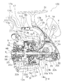
本発明の一実施形態を採用した釣り糸を前方に繰り出すスピニングリール100は、図1に示すように、釣り竿の長手方向に沿う第1軸X回りに釣り糸を巻き取るレバーブレーキ型(ロータ制動型)のリールである。スピニングリール100は、リール本体2と、スプール軸8と、スプール4と、ロータ3と、回転伝達機構5と、回転制御機構7と、ロータ制動機構6と、を備える。リール本体2は、ハンドル1が側部に回転自在に装着されるものである。スプール軸8は、リール本体2に第1軸X方向に前後移動自在に支持される。スプール4は、スプール軸8の先端に設けられる糸巻用のものである。ロータ3は、リール本体2の前部に第1軸X回りに回転自在に設けられ、スプールに釣り糸を巻き付けるためのものである。回転伝達機構5は、ハンドル1の回転をロータ3に伝達するものである。ロータ制動機構6は、ロータの糸繰り出し方向の回転を制動する。回転制御機構7は、ハンドルとロータ3との間に配置され、ハンドル1が回転すると、ハンドル1からの回転をロータ3に伝達し、ロータ3が回転すると、ロータ3からの回転をハンドル1に伝達せず、かつロータ3を自由回転可能に制御する。
<Overall configuration>
As shown in FIG. 1, a spinning reel 100 that feeds a fishing line forward that employs an embodiment of the present invention has a lever brake type (rotor braking type) that winds the fishing line around a first axis X along the longitudinal direction of the fishing rod. It is a reel. The spinning reel 100 includes a reel body 2, a spool shaft 8, a spool 4, a rotor 3, a rotation transmission mechanism 5, a rotation control mechanism 7, and a rotor braking mechanism 6. The reel body 2 has a handle 1 mounted rotatably on the side. The spool shaft 8 is supported by the reel body 2 so as to be movable back and forth in the first axis X direction. The spool 4 is for bobbin winding provided at the tip of the spool shaft 8. The rotor 3 is provided at the front portion of the reel body 2 so as to be rotatable around the first axis X, and is used for winding a fishing line around the spool. The rotation transmission mechanism 5 transmits the rotation of the handle 1 to the rotor 3. The rotor braking mechanism 6 brakes the rotation of the rotor in the yarn feeding direction. The rotation control mechanism 7 is disposed between the handle and the rotor 3. When the handle 1 rotates, the rotation from the handle 1 is transmitted to the rotor 3. When the rotor 3 rotates, the rotation from the rotor 3 is transmitted to the handle 1. The rotor 3 is controlled so as to be freely rotatable without transmission.

<リール本体の構成>
リール本体2は、例えばマグネシウム合金製である。リール本体2は、図1、図2、図3及び図4に示すように、釣り竿に装着される前後に長い竿装着部2cと、竿装着部2cと間隔を隔てて配置されたリールボディ2aと、竿装着部2cとリールボディ2aとを連結する脚部2bとを有する。リールボディ2aは、内部に機構装着空間を有し、脚部2bと一体形成され側部が開口する。リールボディ2aの開口は、蓋部材2d(図2及び図3参照)により塞がれている。また、リール本体2は、リールボディ2aの前部に固定されたアルミニウム合金などの金属製の第1取付部材25と、第1取付部材25に固定された同じくアルミニウム合金製の筒状の第2取付部材26と、をさらに有する。第1取付部材25は、ロータ制動機構6を取り付けるために設けられる。図3に示すように、第1取付部材25は、リールボディ2aの先端部に固定するための固定部25aと、第2取付部材26を取り付けるための筒状部分25bと、を有する。筒状部分25bには第2取付部材26がねじ込まれる雌ねじ部25cが形成される。図5に示すように、第2取付部材26は、回転制御機構7を取り付けるために設けられる。第2取付部材26は、大径の鍔部26aと鍔部26aの後部に設けられる雄ねじ部26bと、雄ねじ部26bと並べて配置される第1外周部26cと、第1外周部26cと鍔部26aを挟んで配置される第2外周部26dと、を有する。
<Structure of reel body>
The reel body 2 is made of, for example, a magnesium alloy. As shown in FIGS. 1, 2, 3, and 4, the reel body 2 includes a long rod mounting portion 2c before and after being mounted on a fishing rod, and a reel body 2a that is spaced from the rod mounting portion 2c. And leg portions 2b that connect the hook mounting portion 2c and the reel body 2a. The reel body 2a has a mechanism mounting space inside, is integrally formed with the leg 2b, and has a side opening. The opening of the reel body 2a is closed by a lid member 2d (see FIGS. 2 and 3). The reel body 2 includes a first mounting member 25 made of metal such as an aluminum alloy fixed to the front portion of the reel body 2a, and a cylindrical second member made of the same aluminum alloy fixed to the first mounting member 25. And an attachment member 26. The first attachment member 25 is provided for attaching the rotor braking mechanism 6. As shown in FIG. 3, the first mounting member 25 has a fixing portion 25 a for fixing to the tip end portion of the reel body 2 a and a cylindrical portion 25 b for mounting the second mounting member 26. An internal thread portion 25c into which the second attachment member 26 is screwed is formed in the cylindrical portion 25b. As shown in FIG. 5, the second attachment member 26 is provided for attaching the rotation control mechanism 7. The second mounting member 26 includes a large-diameter collar part 26a, a male screw part 26b provided at the rear part of the collar part 26a, a first outer peripheral part 26c arranged side by side with the male screw part 26b, a first outer peripheral part 26c, and a collar part. 26a, and a second outer peripheral portion 26d arranged with 26a interposed therebetween.

リールボディ2a及び蓋部材2dの後部は、ガード部材35により覆われる。脚部2bの前面には、後述する制動レバー17を収容するための装着溝2eが形成される。装着溝2eは、断面が概ね三日月形状に形成される。装着溝2eには、例えば、ポリアセタール等の合成樹脂絶縁体製のシート部材18が装着される。   The rear portions of the reel body 2a and the lid member 2d are covered with a guard member 35. A mounting groove 2e for accommodating a later-described braking lever 17 is formed on the front surface of the leg 2b. The mounting groove 2e has a substantially crescent-shaped cross section. In the mounting groove 2e, for example, a sheet member 18 made of a synthetic resin insulator such as polyacetal is mounted.

リールボディ2aの内部には、図1に示すように、回転伝達機構5と、ロータ制動機構6と、回転制御機構7と、オシレーティング機構20とが設けられる。オシレーティング機構20は、ハンドル1の回転に連動してスプール軸8を介してスプール4を前後に往復移動させる機構である。   As shown in FIG. 1, a rotation transmission mechanism 5, a rotor braking mechanism 6, a rotation control mechanism 7, and an oscillating mechanism 20 are provided inside the reel body 2a. The oscillating mechanism 20 is a mechanism for reciprocating the spool 4 back and forth via the spool shaft 8 in conjunction with the rotation of the handle 1.

<ハンドルの構成>
ハンドル1は、図2に示すように、後述する駆動軸10にねじ込み固定されるねじ込み式のものである。ハンドル1は、駆動軸10にねじ込まれるねじ軸37と、ねじ軸37に折り畳み可能に設けられたハンドルアーム38と、ハンドルアーム38の先端にねじ軸37と平行な軸回りに回転自在に装着されたハンドル把手39と、を有する。また、ハンドル1は、ねじ軸37とハンドルアーム38とを連結する連結ピン47と、ねじ軸37の外周側で駆動軸10とハンドルアーム38との間に配置された軸つば部材49と、をさらに有する。ねじ軸37の先端には、左ねじの第1ねじ部37aと、右ねじの第2ねじ部37bと、が形成される。ハンドル1は、図2に示す右位置とその逆側の左位置とのいずれにも取付可能である。ハンドル1が取り付けられた位置と逆側の位置のリール本体2にはキャップ部材69が装着される。
<Composition of handle>
As shown in FIG. 2, the handle 1 is of a screw type that is screwed and fixed to a drive shaft 10 to be described later. The handle 1 is attached to a screw shaft 37 to be screwed into the drive shaft 10, a handle arm 38 that is foldable on the screw shaft 37, and a tip of the handle arm 38 that is rotatable around an axis parallel to the screw shaft 37. Handle handle 39. The handle 1 includes a connecting pin 47 that connects the screw shaft 37 and the handle arm 38, and a shaft collar member 49 that is disposed between the drive shaft 10 and the handle arm 38 on the outer peripheral side of the screw shaft 37. Also have. A left screw first screw portion 37 a and a right screw second screw portion 37 b are formed at the tip of the screw shaft 37. The handle 1 can be attached to either the right position shown in FIG. 2 or the left position on the opposite side. A cap member 69 is attached to the reel body 2 at a position opposite to the position where the handle 1 is attached.

<ロータの構成>
ロータ3は、たとえばマグネシウム合金製であり、リール本体2に回転自在に支持される。ロータ3は、円筒部3aと、円筒部3aの側方に互いに対向して設けられた第1アーム部3b及び第2アーム部3cとを有する。円筒部3aの前壁3dの中央部には貫通孔3fを有するボス部3eが形成される。この貫通孔3fにスプール軸8、回転制御機構7、及び後述するピニオンギア12が貫通する。ボス部3eの外周面には、図4に示すように、環状のばね装着溝3gを有する環状のばね取付部材3hが一体回転可能に装着される。また、図1に示すように、第1アーム部3bの先端と第2アーム部3cの先端部とには、ベールアーム9が揺動自在に設けられる。このベールアーム9により釣り糸がスプール4に案内される。
<Configuration of rotor>
The rotor 3 is made of, for example, a magnesium alloy and is rotatably supported by the reel body 2. The rotor 3 includes a cylindrical part 3a and a first arm part 3b and a second arm part 3c provided on the side of the cylindrical part 3a so as to face each other. A boss 3e having a through hole 3f is formed at the center of the front wall 3d of the cylindrical portion 3a. The spool shaft 8, the rotation control mechanism 7, and a pinion gear 12 described later pass through the through hole 3f. As shown in FIG. 4, an annular spring mounting member 3h having an annular spring mounting groove 3g is mounted on the outer peripheral surface of the boss portion 3e so as to be integrally rotatable. Further, as shown in FIG. 1, bail arms 9 are swingably provided at the tip of the first arm portion 3b and the tip of the second arm portion 3c. The fishing line is guided to the spool 4 by the bail arm 9.

<スプールの構成>
スプール4は、たとえばアルミニウム合金製のものであり、図1に示すように、ロータ3の第1アーム部3bと第2アーム部3cとの間に配置される。スプール4は、スプール軸8の先端にワンタッチ着脱機構48を介して着脱自在かつ回転可能に装着される。スプール4は、スプール本体22と、スプール本体22内に配置されたドラグ機構23と、スプール本体22を回転自在に支持するスプール筒部24と、を有する。スプール本体22は、筒状の糸巻胴部22aと、糸巻胴部22aの後端部に糸巻胴部22aより大径に形成された筒状のスカート部22bと、糸巻胴部22aの前部に前方に傾斜して形成されたフランジ部22cと、を有する。
<Spool configuration>
The spool 4 is made of, for example, an aluminum alloy, and is disposed between the first arm portion 3b and the second arm portion 3c of the rotor 3 as shown in FIG. The spool 4 is detachably and rotatably attached to the tip of the spool shaft 8 via a one-touch attachment / detachment mechanism 48. The spool 4 includes a spool body 22, a drag mechanism 23 disposed in the spool body 22, and a spool cylinder portion 24 that rotatably supports the spool body 22. The spool body 22 has a cylindrical bobbin trunk 22a, a cylindrical skirt 22b formed at the rear end of the bobbin trunk 22a with a larger diameter than the bobbin trunk 22a, and a front part of the bobbin trunk 22a. And a flange portion 22c formed to be inclined forward.

ドラグ機構23は、ドラグつまみ60を有するドラグ調整部58と、ドラグ調整部58により押圧される1又は複数のドラグ座金を有する摩擦部59と、を有する。ドラグ調整部58は、スプール軸8の先端に螺合してドラグ力を調整する。複数のドラグ座金は、スプール筒部24に回転自在又は回転不能に連結される。   The drag mechanism 23 includes a drag adjusting portion 58 having a drag knob 60 and a friction portion 59 having one or more drag washers pressed by the drag adjusting portion 58. The drag adjusting unit 58 is screwed to the tip of the spool shaft 8 to adjust the drag force. The plurality of drag washers are coupled to the spool cylinder 24 so as to be rotatable or non-rotatable.

スプール筒部24は、スプール軸8に回転不能かつ着脱自在に装着される。スプール筒部24は、ワンタッチ着脱機構48によりスプール本体22及びドラグ機構23とともにスプール軸8からワンタッチで着脱可能である。   The spool cylinder portion 24 is attached to the spool shaft 8 in a non-rotatable and detachable manner. The spool cylinder portion 24 can be attached and detached from the spool shaft 8 together with the spool body 22 and the drag mechanism 23 by a one-touch attachment / detachment mechanism 48.

<回転伝達機構の構成>
回転伝達機構5は、図1、図2及び図3に示すように、ハンドル1が一体回転可能に固定される駆動軸10と、駆動軸10ともに回転する駆動ギア11と、駆動ギア11に噛み合うピニオンギア12と、を有する。駆動軸10は、駆動ギア11と一体で筒状に形成される。駆動軸10は、リールボディ2a及び蓋部材2dにそれぞれ軸受15a,15b(図2)により回転自在に支持される。駆動軸10の図2右側端部の内周面には、第2ねじ部37bに螺合する第2雌ねじ部10bが形成され、図2左側端部から第2ねじ部37bの長さ分奥側内周面には、第1ねじ部37aに螺合する第1雌ねじ部10aが形成される。
<Configuration of rotation transmission mechanism>
Rotation transmission mechanism 5, as shown in FIGS. 1, 2 and 3, a drive shaft 10 which the handle 1 is integrally rotatably fixed, together with the driving gear 11 which rotates the drive shaft 10, the drive gear 11 An intermeshing pinion gear 12. The drive shaft 10 is formed in a cylindrical shape integrally with the drive gear 11. The drive shaft 10 is rotatably supported by the reel body 2a and the lid member 2d by bearings 15a and 15b (FIG. 2), respectively. A second female screw portion 10b that is screwed into the second screw portion 37b is formed on the inner peripheral surface of the right end portion in FIG. 2 of the drive shaft 10, and is deeper by the length of the second screw portion 37b from the left end portion in FIG. A first female screw portion 10a that is screwed into the first screw portion 37a is formed on the side inner peripheral surface.

ピニオンギア12は、図1に示すように、筒状に形成されており、ピニオンギア12の前部12aは回転制御機構7を貫通してスプール4側に延びている。ピニオンギア12は、中間部と後部とで軸受14a、14bによりリールボディ2aに回転自在に支持される。図3に示すように、ピニオンギア12の前部12aには、回転制御機構7の後述する第1筒部50を連結するためのナット13がねじ込まれる雄ねじ部12bと、第1筒部50に一体回転可能に係合する平行に形成された一対の面取り部12dを有する非円形部12cとが形成される。ピニオンギア12は、前部12aで第2取付部材26の内周面に装着された軸受14cによって第2取付部材26に回転自在に支持される。ナット13は、大径部13aと、大径部13aと軸方向に並べて配置された小径部13bと、を有する大径部13aは、外周部に、例えば六角形に形成された工具係止部13cと、内周部に円形に形成された軸受収容部13dとを有する。小径部13bは、第1筒部50を軸受14cに向けて押圧するとともに、第1筒部50に嵌合して第1筒部50を芯出しする。ナット13は、軸受収容部13dに装着された軸受36によってスプール軸8に接触する。これにより、ピニオンギア12の内周面とスプール軸8の外周面との間に隙間を形成できる。 As shown in FIG. 1, the pinion gear 12 is formed in a cylindrical shape, and a front portion 12 a of the pinion gear 12 extends through the rotation control mechanism 7 to the spool 4 side. The pinion gear 12 is rotatably supported on the reel body 2a by bearings 14a and 14b at an intermediate portion and a rear portion. As shown in FIG. 3, the front part 12 a of the pinion gear 12 has a male screw part 12 b into which a nut 13 for connecting a first cylinder part 50 to be described later of the rotation control mechanism 7 is screwed, and a first cylinder part 50. A non-circular portion 12c having a pair of chamfered portions 12d formed in parallel to engage with each other is formed. The pinion gear 12 is rotatably supported by the second mounting member 26 by a bearing 14c mounted on the inner peripheral surface of the second mounting member 26 at the front portion 12a. The nut 13 has a large-diameter portion 13a and a small-diameter portion 13b arranged side by side with the large-diameter portion 13a in the axial direction . The large-diameter portion 13a has, for example, a tool locking portion 13c formed in a hexagonal shape on the outer peripheral portion and a bearing accommodating portion 13d formed in a circular shape on the inner peripheral portion. The small diameter portion 13b presses the first tube portion 50 toward the bearing 14c and is fitted to the first tube portion 50 to center the first tube portion 50. The nut 13 comes into contact with the spool shaft 8 by a bearing 36 attached to the bearing housing portion 13d. Thereby, a gap can be formed between the inner peripheral surface of the pinion gear 12 and the outer peripheral surface of the spool shaft 8.

<オシレーティング機構の構成>
オシレーティング機構20は、図1及び図2に示すように、トラバースカム式のものである。オシレーティング機構20は、ピニオンギア12に噛み合う中間ギア20aと、リールボディ2aにスプール軸8と平行な軸回りに回転自在に装着された螺軸20bと、螺軸20bの回転により前後移動するスライダ20cと、を有する。スライダ20cにスプール軸8の後端部が回転不能かつ軸方向移動不能に取り付けられる。
<Configuration of oscillating mechanism>
As shown in FIGS. 1 and 2, the oscillating mechanism 20 is of a traverse cam type. The oscillating mechanism 20 includes an intermediate gear 20a that meshes with the pinion gear 12, a screw shaft 20b that is rotatably mounted on the reel body 2a around an axis parallel to the spool shaft 8, and a slider that moves back and forth by the rotation of the screw shaft 20b. 20c. The rear end portion of the spool shaft 8 is attached to the slider 20c so that it cannot rotate but cannot move in the axial direction.

<回転制御機構の構成>
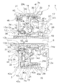
回転制御機構7は、図4に示すように、この実施形態では、ピニオンギア12とロータ3との間に配置されるローラクラッチである。回転制御機構7は、図4、図5及び図6に示すように、ピニオンギア12の前部12aに一体回転可能に連結される第1筒部(内輪)50と、第1筒部50の外周側に配置される第2筒部(外輪)51と、複数のローラ52と、第1筒部50に設けられる複数のローラ収容凹部53(図5及び図6参照)と、切換機構54と、を有する。したがって、回転制御機構7は、外輪である第2筒部51が遊転する外輪遊転型のものである。
<Configuration of rotation control mechanism>
As shown in FIG. 4, the rotation control mechanism 7 is a roller clutch disposed between the pinion gear 12 and the rotor 3 in this embodiment. Rotation control mechanism 7, as shown in FIGS. 4, 5 and 6, the first cylindrical portion which is linked to one body rotating to the front 12a of the pinion gear 12 (the inner ring) 50, the first cylindrical portion 50, the 2nd cylinder part (outer ring) 51 arrange | positioned at the outer peripheral side, the some roller 52, the some roller accommodating recessed part 53 (refer FIG.5 and FIG.6) provided in the 1st cylinder part 50, and a switching mechanism 54. Therefore, the rotation control mechanism 7 is an outer ring idle type in which the second cylinder portion 51 that is an outer ring idles.

<第1筒部の構成>
第1筒部50は、図4に示すように、ナット13によってピニオンギア12の前部12aに一体回転可能に連結される。図5に示すように、第1筒部50は、軸方向に並べて配置された嵌合部50aと非円形孔50bとを有する。嵌合部50aは内周面にナット13の小径部13bが嵌合する。非円形孔50bはピニオンギア12の非円形部12cに一体的に回転可能に係合する。第1筒部50は、外周部に軸方向に並べて配置された大径の鍔部50cと、中径のローラ配置部50dと、小径の当接部50eと、を有する。鍔部50cは、切換機構54の後述する付勢部材57の先端部を装着するための装着溝50f(図参照)が設けられる。装着溝50fは、径方向に沿って形成される。ローラ配置部50dにはローラ収容凹部53が設けられる。当接部50eは、軸受14cの内輪に当接し軸受14cを位置決めする。
<Configuration of first tube portion>
As shown in FIG. 4, the first tube portion 50 is connected to the front portion 12 a of the pinion gear 12 by a nut 13 so as to be integrally rotatable. As shown in FIG. 5, the 1st cylinder part 50 has the fitting part 50a and the non-circular hole 50b which were arrange | positioned along with the axial direction. The small diameter portion 13b of the nut 13 is fitted to the inner peripheral surface of the fitting portion 50a. The non-circular hole 50b engages with the non-circular portion 12c of the pinion gear 12 so as to be integrally rotatable. The first cylinder portion 50 includes a large-diameter flange portion 50c arranged in the axial direction on the outer peripheral portion, a medium-diameter roller arrangement portion 50d, and a small-diameter contact portion 50e. The flange portion 50c is provided with a mounting groove 50f (see FIG. 4 ) for mounting a distal end portion of a biasing member 57 described later of the switching mechanism 54. The mounting groove 50f is formed along the radial direction. A roller receiving recess 53 is provided in the roller placement portion 50d. The contact portion 50e contacts the inner ring of the bearing 14c and positions the bearing 14c.

<第2筒部の構成>
第2筒部51は、第1筒部50の外周側に配置される。第2筒部51は、ローラ52が接触可能な円形の内周部51aを有する。第2筒部51の円形の外周部51bには、ロータ3のボス部3eの貫通孔3fに形成された複数(例えば6個)の係合凹部3i(図6参照)に係合する複数(例えば6個)の係合凸部51cと、第2筒部51をボス部3eに連結するための雄ねじ部51d(図5参照)とが軸方向に並べて配置される。これによって第2筒部51はロータ3のボス部3eに一体回転可能に連結される。係合凹部3i及び係合凸部51cは、周方向に一部が不等間隔となるように配置される。図4に示すように、雄ねじ部51dは、ロータ3の前壁3dから突出して配置される。この前壁3d側から、ナット部材63が雄ねじ部51dにねじ込まれ、第2筒部51がロータ3に一体的に回転可能に連結される。
<Configuration of second tube portion>
The second cylinder portion 51 is disposed on the outer peripheral side of the first cylinder portion 50. The 2nd cylinder part 51 has the circular inner peripheral part 51a with which the roller 52 can contact. A plurality of (for example, six) engagement recesses 3i (see FIG. 6) formed in the through holes 3f of the boss 3e of the rotor 3 are engaged with the circular outer peripheral portion 51b of the second cylindrical portion 51 (see FIG. 6). For example, six engaging convex portions 51c and male screw portions 51d (see FIG. 5) for connecting the second cylindrical portion 51 to the boss portion 3e are arranged side by side in the axial direction. This second cylindrical portion 51 is linked to the rolling one body times the boss 3e of the rotor 3. The engagement recesses 3i and the engagement protrusions 51c are arranged so that parts thereof are unequally spaced in the circumferential direction. As shown in FIG. 4, the male screw portion 51 d is disposed so as to protrude from the front wall 3 d of the rotor 3. From the front wall 3d side, the nut member 63 is screwed into the male screw portion 51d, and the second cylinder portion 51 is connected to the rotor 3 so as to be integrally rotatable.

<ローラの構成>
複数(例えば6個)のローラ52は、図5及び図6に示すように、第1筒部50と第2筒部51との間で周方向に間隔を隔てて配置される。ローラ52は、円柱形状であり、ローラ収容凹部53の中央部から周方向の両側に僅かに移動可能である。
<Roller configuration>
As shown in FIGS. 5 and 6, the plurality of (for example, six) rollers 52 are disposed between the first cylindrical portion 50 and the second cylindrical portion 51 with an interval in the circumferential direction. The roller 52 has a cylindrical shape, and is slightly movable from the central portion of the roller accommodating recess 53 to both sides in the circumferential direction.

<ローラ収容凹部の構成>
複数(例えば6個)のローラ収容凹部53は、ローラ52が配置される位置で第1筒部50の外周部に周方向に間隔を隔てて円弧状に凹んで設けられる。ローラ収容凹部53は、図6の拡大部分に示すように、ローラ52との間に隙間が形成されローラ52が自転可能な自由回転位置53a、及び自由回転位置53aの両側に対称に設けられローラ52が食い込む2つの回転伝達位置53b、を有する。ローラ収容凹部53の周方向の中央部分が自由回転位置53aであり、その両側に回転伝達位置53bが自由回転位置53aを挟んで対称に配置される。自由回転位置53aにおけるローラ収容凹部53と第2筒部51の内周部との径方向の隙間は、ローラ52の直径よりも大きな径方向長さを有する。ローラ収容凹部53の中心部分から両端に向かって径方向の隙間は徐々に小さくなり、その途中でローラ52の直径以下になる。この位置が回転伝達位置53bである。すなわち、第2筒部51とローラ収容凹部53との隙間がローラ52の直径以下になる回転伝達位置53bでローラ52がローラ収容凹部53と第2筒部51との間に食い込む。これによって、第1筒部50の回転が第2筒部51に伝達される。なお、図6の拡大部分には、二点鎖線で回転伝達位置53bにあるローラ52を示す。
<Configuration of roller receiving recess>
A plurality of (for example, six) roller receiving recesses 53 are provided in the outer peripheral portion of the first cylindrical portion 50 at a position where the roller 52 is disposed, and are recessed in an arc shape at intervals in the circumferential direction. As shown in the enlarged portion of FIG. 6, the roller housing recess 53 is formed symmetrically on both sides of the free rotation position 53a and a free rotation position 53a in which a gap is formed between the roller 52 and the roller 52 can rotate. There are two rotation transmission positions 53b into which 52 bites. A central portion in the circumferential direction of the roller receiving recess 53 is a free rotation position 53a, and rotation transmission positions 53b are symmetrically arranged on both sides of the free rotation position 53a. The radial gap between the roller receiving recess 53 and the inner peripheral portion of the second cylindrical portion 51 at the free rotation position 53 a has a radial length larger than the diameter of the roller 52. The radial gap gradually decreases from the central portion of the roller accommodating recess 53 toward both ends, and becomes smaller than the diameter of the roller 52 in the middle. This position is the rotation transmission position 53b. That is, the roller 52 bites between the roller accommodating recess 53 and the second cylindrical portion 51 at the rotation transmission position 53 b where the gap between the second cylindrical portion 51 and the roller accommodating concave portion 53 is equal to or less than the diameter of the roller 52. Thereby, the rotation of the first cylinder part 50 is transmitted to the second cylinder part 51. Note that the enlarged portion of FIG. 6 shows the roller 52 at the rotation transmission position 53b by a two-dot chain line.

<切換機構の構成>
切換機構54は、第1筒部50が第2筒部51に対していずれの方向に回転しても、ローラ52を回転伝達位置53bに移動させ、第1筒部50の回転が停止するとローラ52を自由回転位置53aに戻す。また、第2筒部51が第1筒部50に対して回転したときもローラ52を自由回転位置53aに維持する。切換機構54は、間隔保持部材55と、切換部材56と、付勢部材57と、を有する。間隔保持部材55は、例えば合成樹脂製の筒状の部材であり、第1筒部50の外周面および第2筒部51の内周面に大部分が隙間をあけて配置され、かつ一部が第1筒部50の外周面および第2筒部51の内周面に接触して配置される。
<Configuration of switching mechanism>
The switching mechanism 54 moves the roller 52 to the rotation transmission position 53b regardless of which direction the first tube portion 50 rotates with respect to the second tube portion 51, and when the rotation of the first tube portion 50 stops, the roller 52 is returned to the free rotation position 53a. Further, the roller 52 is maintained at the free rotation position 53a even when the second cylinder portion 51 rotates with respect to the first cylinder portion 50. The switching mechanism 54 includes a spacing member 55, a switching member 56, and an urging member 57. The interval holding member 55 is, for example, a cylindrical member made of synthetic resin, and most of the interval holding member 55 is disposed with a gap between the outer peripheral surface of the first cylindrical portion 50 and the inner peripheral surface of the second cylindrical portion 51. Are arranged in contact with the outer peripheral surface of the first cylindrical portion 50 and the inner peripheral surface of the second cylindrical portion 51.

間隔保持部材55には、図5、図6及び図7に示すように、周方向に等間隔に配置された概ね矩形の複数(例えば6個)のローラ収容孔55aを有する。また、軸方向の一方の端部(例えば後側の端部)には、切換部材56が係止される第1切欠き部55bが形成される。他方の端部(例えば前側の端部)には、付勢部材57が係止される第2切欠き部55cが形成される。ローラ収容孔55aは、ローラ収容凹部53と同じ周方向間隔(例えば60度間隔)に形成される。ローラ収容孔55aとローラ52との間には、周方向及び軸方向に僅かに隙間が形成される。第1切欠き部55bおよび第2切欠き部55cは、ローラ収容孔55aの間で180度位相をずらして配置される。   As shown in FIGS. 5, 6, and 7, the interval holding member 55 includes a plurality of (for example, six) roller receiving holes 55 a that are substantially rectangular and are arranged at equal intervals in the circumferential direction. In addition, a first notch 55b to which the switching member 56 is locked is formed at one end in the axial direction (for example, the rear end). A second notch 55c to which the biasing member 57 is locked is formed at the other end (for example, the front end). The roller accommodation holes 55a are formed at the same circumferential interval (for example, 60 ° interval) as the roller accommodation recesses 53. A slight gap is formed between the roller receiving hole 55a and the roller 52 in the circumferential direction and the axial direction. The first cutout portion 55b and the second cutout portion 55c are arranged with a phase difference of 180 degrees between the roller receiving holes 55a.

切換部材56は、間隔保持部材55に連結され、第1筒部50の回転に応じて間隔保持部材55を周方向に移動させ、ローラ52をローラ収容凹部53の自由回転位置53aから回転伝達位置53bに移動させる。切換部材56は、図5及び図7に示すように、ばね性を有する金属製板材をC字状に湾曲して形成され、第2取付部材26の第2外周部26dに摩擦係合して摺動する摺動部56aと、摺動部56aの一端に折れ曲がって第1筒部50から離反する方向に延びる第1係合部56bと、摺動部56aの他端から折れ曲がって第1筒部50から離反する方向に延びる第2係合部56cと、を有する。摺動部56aの自由直径は、第2外周部26dが外径よりも小さい。このため、切換部材56は、第2外周部26dに摩擦係合する。   The switching member 56 is connected to the interval holding member 55, moves the interval holding member 55 in the circumferential direction in accordance with the rotation of the first tube portion 50, and moves the roller 52 from the free rotation position 53 a of the roller accommodating recess 53 to the rotation transmission position. Move to 53b. As shown in FIGS. 5 and 7, the switching member 56 is formed by bending a metal plate material having a spring property into a C shape, and is frictionally engaged with the second outer peripheral portion 26 d of the second mounting member 26. A sliding portion 56a that slides, a first engagement portion 56b that is bent at one end of the sliding portion 56a and extends away from the first tube portion 50, and a first tube that is bent from the other end of the sliding portion 56a And a second engagement portion 56c extending in a direction away from the portion 50. The free diameter of the sliding part 56a is smaller than the outer diameter of the second outer peripheral part 26d. For this reason, the switching member 56 frictionally engages with the second outer peripheral portion 26d.

付勢部材57は、ばね性を有する金属製の板材をU字状に折り曲げて形成される。付勢部材57は、間隔保持部材55を介して複数のローラ52を自由回転位置53aに向けて付勢する。すなわち、付勢部材57は、ローラ52を回転伝達位置53bから自由回転位置53aに戻すために設けられる。付勢部材57は、折り曲げられた基端部57aが第2切欠き部55cに係合し、2つの先端部57bが第1筒部50の鍔部50cに形成された装着溝50fに係合する。装着溝50fの周方向の幅は、先端部57bの自由幅よりも短い。このため、付勢部材57は、先端部57bが僅かに自由幅よりも短い幅となるように弾性的に縮められた状態で装着溝50fに装着される。これによって、間隔保持部材55を介してローラ52を自由回転位置53aに付勢し、ローラ52を自由回転位置53aにセンタリングする。   The urging member 57 is formed by bending a metal plate having spring properties into a U shape. The urging member 57 urges the plurality of rollers 52 toward the free rotation position 53a via the interval holding member 55. That is, the urging member 57 is provided to return the roller 52 from the rotation transmission position 53b to the free rotation position 53a. In the urging member 57, the bent base end portion 57a is engaged with the second notch portion 55c, and the two distal end portions 57b are engaged with the mounting groove 50f formed in the flange portion 50c of the first tube portion 50. To do. The circumferential width of the mounting groove 50f is shorter than the free width of the tip portion 57b. For this reason, the urging member 57 is mounted in the mounting groove 50f in a state in which the distal end portion 57b is elastically contracted so that the width is slightly shorter than the free width. As a result, the roller 52 is urged to the free rotation position 53a via the spacing member 55, and the roller 52 is centered to the free rotation position 53a.

このような構成の回転制御機構7では、第1筒部50が一方向に回転すると、間隔保持部材55がローラ52を介して第1筒部50に連動して同じ方向に回転する。この間隔保持部材55の回転によって、第1切欠き部55bの周方向の壁部に切換部材56の第1係合部56b又は第2係合部56cが接触する。第1係合部56b又は第2係合部56cが壁部に接触すると、切換部材56は、第2外周部26dに対して摺動部56aが摩擦係合しながら回転する。この摩擦係合によって、間隔保持部材55の回転が切換部材56によって制動され、間隔保持部材55が第1筒部50に対して相対的に僅かに他方向に回転する。この間隔保持部材55の他方向への相対回転によって、間隔保持部材55を介してローラ52が自由回転位置53aから回転伝達位置53bに移動し、ローラ52がローラ収容凹部53に食い込む。これによって、ローラ52を介して第1筒部50の回転が第2筒部51に伝達され、ロータ3が回転する。ピニオンギア12の回転が停止すると、付勢部材57によってローラ52が自由回転位置53aになるように間隔保持部材55が付勢され、ローラ52が自由回転位置53aに戻る。 In the rotation control mechanism 7 having such a configuration, when the first tube portion 50 rotates in one direction, the spacing member 55 rotates in the same direction in conjunction with the first tube portion 50 via the roller 52. By the rotation of the spacing member 55, the first engaging portion 56b or the second engaging portion 56c of the switching member 56 contacts the circumferential wall portion of the first notch portion 55b. When the first engaging portion 56b or the second engaging portion 56c comes into contact with the wall portion, the switching member 56 rotates while the sliding portion 56a is frictionally engaged with the second outer peripheral portion 26d. This frictional engagement, is braked by the rotating switching member 56 of the spacing members 55, the spacing members 55 to rotate relative slightly other direction with respect to the first cylindrical portion 50. By the relative rotation of the gap holding member 55 in the other direction, the roller 52 moves from the free rotation position 53 a to the rotation transmission position 53 b via the gap holding member 55, and the roller 52 bites into the roller housing recess 53. Thereby, the rotation of the first cylinder portion 50 is transmitted to the second cylinder portion 51 via the roller 52, and the rotor 3 rotates. When the rotation of the pinion gear 12 stops, the biasing member 57 roller 52 is energized spacing member 55 so that the free rotation position 53a, the roller 52 returns to the free rotation position 53a.

例えば、ハンドル1の糸巻き取り方向回転によってピニオンギア12が糸巻き取り方向に回転すると、ピニオンギア12の回転が回転制御機構7を介してロータ3に伝達される。これによって、ロータ3がピニオンギア12と同じ方向に回転し、スプール4に巻き付け可能になる。このことは、ピニオンギア12が糸繰り出し方向R2に回転しても、同様に切換部材56の第2係合部56cが間隔保持部材55を糸繰り出し方向R2に押圧してロータを糸繰り出し方向に回転させる。 For example, when the pinion gear 12 rotates in the yarn winding direction by the rotation of the handle 1 in the yarn winding direction , the rotation of the pinion gear 12 is transmitted to the rotor 3 via the rotation control mechanism 7. As a result, the rotor 3 rotates in the same direction as the pinion gear 12 and can be wound around the spool 4. This also rotates in the direction R2 pinion gear 12 is feeding the yarn, likewise yarn feeding direction second engagement portion 56c is the rotor 3 is pressed against the yarn feeding direction R2 of the spacing member 55 of the switching member 56 Rotate to

一方、ロータ3がいずれの方向に回転しても、第2筒部51にはローラ収容凹部53が設けられていないので、第2筒部51が回転するだけで、切換部材56が回転しない、このため、ロータ3がいずれの方向に回転しても、ピニオンギア12が回転せず、ハンドル1が回転しない。   On the other hand, no matter which direction the rotor 3 rotates, since the second cylinder portion 51 is not provided with the roller accommodating recess 53, only the second cylinder portion 51 rotates and the switching member 56 does not rotate. For this reason, no matter which direction the rotor 3 rotates, the pinion gear 12 does not rotate and the handle 1 does not rotate.

ここでは、第1筒部50にハンドル1の回転が伝達され、第2筒部51にロータ3の回転が伝達されるように、第1筒部50及び第2筒部51を配置することによって、操作部材を操作することなく、ハンドル1の回転をロータに常時伝達できるようになる。このため、操作部材の操作忘れによって、ロータ3を糸巻き取り方向に回転させることができない状態が生じなくなり、魚の当たりに対して適切に対応できる。   Here, by arranging the first cylinder part 50 and the second cylinder part 51 so that the rotation of the handle 1 is transmitted to the first cylinder part 50 and the rotation of the rotor 3 is transmitted to the second cylinder part 51. The rotation of the handle 1 can always be transmitted to the rotor without operating the operating member. For this reason, the state in which the rotor 3 cannot be rotated in the yarn winding direction does not occur due to forgetting to operate the operation member, and it is possible to appropriately cope with the fish hit.

<ロータ制動機構の構成>
ロータ制動機構6は、図1、図3、図4及び図5に示すように、制動部16と、制動部16の制動力を調整操作するための制動レバー(制動操作部材の一例)17と、制動レバー17を付勢するコイルばねの形態のばね部材19と、制動レバー17によって所定制動状態と制動解除状態とに切換可能な所定制動部21(図3参照)とを有する。ばね部材19は、制動レバー17を竿装着部2cから離反する方向に付勢する。
<Configuration of rotor braking mechanism>
As shown in FIGS. 1, 3, 4, and 5, the rotor braking mechanism 6 includes a braking unit 16 and a braking lever (an example of a braking operation member) 17 for adjusting the braking force of the braking unit 16. And a spring member 19 in the form of a coil spring for urging the brake lever 17 and a predetermined brake portion 21 (see FIG. 3) that can be switched between a predetermined brake state and a brake release state by the brake lever 17. The spring member 19 biases the brake lever 17 in a direction away from the saddle mounting portion 2c.

<制動部の構成>
制動部16は、図4に示すように、制動レバー17の先端が圧接されて制動される制動面41aを有する制動部本体31と、ロータ3と制動部本体31とをロータ3の回転方向に応じて連結・遮断する爪式の第1ワンウェイクラッチ32とを有する。
<Configuration of braking unit>
As shown in FIG. 4, the braking unit 16 includes a braking unit body 31 having a braking surface 41 a that is braked by pressing the tip of the braking lever 17, the rotor 3, and the braking unit body 31 in the rotational direction of the rotor 3. And a claw-type first one-way clutch 32 that is connected and disconnected accordingly.

制動部本体31は、ロータ3の円筒部3aの内周側にロータ3と同心に配置された筒状部材40と、筒状部材40の内周面に固定された制動円筒41とを有する。   The brake part main body 31 includes a cylindrical member 40 disposed concentrically with the rotor 3 on the inner peripheral side of the cylindrical part 3 a of the rotor 3, and a brake cylinder 41 fixed to the inner peripheral surface of the cylindrical member 40.

筒状部材40は、図4に示すように、円筒部3aの内周側に同芯に配置される外筒部40aと、外筒部40aの内周側に配置された内筒部40bと、外筒部40aと内筒部40bとを連結する円板部40cと、を有する二重筒状部材である。外筒部40aの外周面には、後述する所定制動部21を構成する摩擦リング30が装着される、例えば2条の環状溝40dが軸方向に間隔を隔てて形成される。内筒部40bは、第2取付部材26の外周面に軸受14dにより回転自在に支持される。第2取付部材26とピニオンギア12との間に軸受14cが配置される。軸受14cは、ピニオンギア12を支持するとともに、第2取付部材26を抜け止めする機能も果たす。軸受14cと軸受14aとの間には、筒状の軸受カラー62が配置される。これにより、軸受14cの後部が位置決めされる。軸受14cの前部は、第1筒部50の当接部50eに接触して位置決めされる。   As shown in FIG. 4, the cylindrical member 40 includes an outer cylindrical portion 40 a disposed concentrically on the inner peripheral side of the cylindrical portion 3 a, and an inner cylindrical portion 40 b disposed on the inner peripheral side of the outer cylindrical portion 40 a And a disc portion 40c that connects the outer cylinder portion 40a and the inner cylinder portion 40b. On the outer peripheral surface of the outer cylinder portion 40a, for example, two annular grooves 40d are formed at intervals in the axial direction, on which a friction ring 30 constituting a predetermined braking portion 21 described later is mounted. The inner cylinder portion 40b is rotatably supported on the outer peripheral surface of the second mounting member 26 by a bearing 14d. A bearing 14 c is disposed between the second mounting member 26 and the pinion gear 12. The bearing 14c supports the pinion gear 12 and also functions to prevent the second mounting member 26 from coming off. A cylindrical bearing collar 62 is disposed between the bearing 14c and the bearing 14a. Thereby, the rear part of the bearing 14c is positioned. The front portion of the bearing 14 c is positioned in contact with the contact portion 50 e of the first tube portion 50.

制動円筒41は、外筒部40aの内周面から内筒部40bを経て軸受14dの外輪の後面に向かって延びている。したがって、軸受14dの外輪は、筒状部材40と制動円筒41とにより挟まれている。制動円筒41は、外筒部40aに沿った内周面が制動面41aとなっている。制動円筒41は、金属製の有底筒状部材であり、円板部40cにねじ止め固定される。この制動円筒41の制動面41aに制動レバー17の先端が当接して筒状部材40を制動する。   The brake cylinder 41 extends from the inner peripheral surface of the outer cylinder portion 40a to the rear surface of the outer ring of the bearing 14d via the inner cylinder portion 40b. Therefore, the outer ring of the bearing 14d is sandwiched between the tubular member 40 and the brake cylinder 41. As for the brake cylinder 41, the inner peripheral surface along the outer cylinder part 40a becomes the brake surface 41a. The brake cylinder 41 is a bottomed cylindrical member made of metal, and is fixed to the disk portion 40c with screws. The tip of the brake lever 17 comes into contact with the brake surface 41a of the brake cylinder 41 to brake the cylindrical member 40.

第1ワンウェイクラッチ32は爪式のものであり、ロータ3が糸繰り出し方向に回転したときにのみロータ3と制動部本体31の筒状部材40とを連結し、ロータ3に連動して筒状部材40を糸繰り出し方向に回転させる。したがって、ロータ3が糸巻取方向に回転したときには、ロータ3と筒状部材40とは遮断され、ロータ3から筒状部材40に回転が伝達されない。第1ワンウェイクラッチ32は、図4及び図5に示すように、ロータ3の円筒部3aの前壁3dに固定されたリング状のラチェットホイール42と、筒状部材40の円板部40cに揺動自在に装着され先端がラチェットホイール42に接触可能なラチェット爪43と、ラチェット爪43を先端がラチェットホイール42に接触する方向に付勢するばね部材44と、ラチェットホイール42と前壁3dとの間に配置された防振部材45とを有する。   The first one-way clutch 32 is of a claw type, and connects the rotor 3 and the tubular member 40 of the braking section main body 31 only when the rotor 3 rotates in the thread take-out direction. The member 40 is rotated in the yarn feeding direction. Therefore, when the rotor 3 rotates in the yarn winding direction, the rotor 3 and the cylindrical member 40 are disconnected, and the rotation is not transmitted from the rotor 3 to the cylindrical member 40. As shown in FIGS. 4 and 5, the first one-way clutch 32 swings on a ring-shaped ratchet wheel 42 fixed to the front wall 3 d of the cylindrical portion 3 a of the rotor 3 and a disc portion 40 c of the cylindrical member 40. A ratchet pawl 43 that is movably mounted and whose tip can contact the ratchet wheel 42, a spring member 44 that biases the ratchet pawl 43 in a direction in which the tip contacts the ratchet wheel 42, the ratchet wheel 42, and the front wall 3d. And an anti-vibration member 45 disposed therebetween.

ラチェットホイール42は、図4に示すように、ロータ3の円筒部3aの前壁3dの後面に複数本の取付ねじ46により固定される。ラチェットホイール42は、前壁3dに固定される円板状のフランジ部42aと、フランジ部42aと一体形成された内周面に鋸歯状のラチェット歯42bが形成された筒状部42cとを有する。フランジ部42aと前壁3dの後面との間に防振部材45が装着される。   As shown in FIG. 4, the ratchet wheel 42 is fixed to the rear surface of the front wall 3 d of the cylindrical portion 3 a of the rotor 3 by a plurality of mounting screws 46. The ratchet wheel 42 includes a disc-shaped flange portion 42a fixed to the front wall 3d, and a cylindrical portion 42c in which sawtooth-like ratchet teeth 42b are formed on an inner peripheral surface integrally formed with the flange portion 42a. . A vibration isolation member 45 is mounted between the flange portion 42a and the rear surface of the front wall 3d.

ラチェット爪43は、ラチェット歯42bに噛み合う噛み合い位置と、ラチェット歯42bから離脱する噛み合い解除位置とに円板部40cに揺動自在に設けられる。ラチェット爪43は、ラチェット歯42bに噛み合う鋭角状に尖った爪部43aを先端に有する。また、ばね部材44が係止される長円形の係止孔43cが形成される。   The ratchet pawl 43 is swingably provided on the disc portion 40c at an engagement position where the ratchet pawl 43 is engaged with the ratchet teeth 42b and an engagement release position where the ratchet pawl 43 is disengaged from the ratchet teeth 42b. The ratchet claw 43 has a claw portion 43a that is sharpened at the tip and meshes with the ratchet teeth 42b. Further, an oval locking hole 43c for locking the spring member 44 is formed.

ばね部材44は、図5に示すように、ばね性を有する金属製線材を湾曲及び折り曲げて形成された部材である。ばね部材44は、ロータ3のボス部3eに形成されたばね装着溝3g(図4)に圧接状態で装着された円形部44aと、円形部44aから径方向外方に延びるアーム部44bと、アーム部44bの先端を係止孔43cに向けて折り曲げた係止突起44cとを有する。係止突起44cは、係止孔43cに挿入され、係止孔43cの内側面を両方向に押圧可能である。また、円形部44aの自由直径は、ばね装着溝3gの底径より小さい。このため、ばね部材44は、ラチェット爪43を噛み合い方向と噛み合い解除方向との両方向に付勢可能な両方向付勢部材である。具体的には、円形部44aがばね装着溝3gに圧接され、ばね部材44は、ロータ3の回転に応じて同じ方向に回転し、噛み合い方向と噛み合い解除方向の両方向にラチェット爪43を付勢する。   As shown in FIG. 5, the spring member 44 is a member formed by bending and bending a metal wire having a spring property. The spring member 44 includes a circular portion 44a mounted in pressure contact with a spring mounting groove 3g (FIG. 4) formed in the boss portion 3e of the rotor 3, an arm portion 44b extending radially outward from the circular portion 44a, and an arm A locking projection 44c is formed by bending the tip of the portion 44b toward the locking hole 43c. The locking projection 44c is inserted into the locking hole 43c and can press the inner surface of the locking hole 43c in both directions. The free diameter of the circular portion 44a is smaller than the bottom diameter of the spring mounting groove 3g. Therefore, the spring member 44 is a bi-directional biasing member that can bias the ratchet pawl 43 in both the meshing direction and the meshing release direction. Specifically, the circular portion 44a is pressed against the spring mounting groove 3g, and the spring member 44 rotates in the same direction according to the rotation of the rotor 3, and urges the ratchet pawl 43 in both the meshing direction and the meshing release direction. To do.

この結果、ロータ3が糸巻取方向(図5の時計回り)に回転するとばね部材44も同方向に回転し、ラチェット爪43を噛み合い解除方向に付勢する。すると、ラチェット爪43が噛み合い解除位置側に揺動する。このため、ロータ3が糸巻取方向に回転したときには、筒状部材40にロータ3の回転が伝達されないとともに、ラチェット爪43がラチェットホイール42に断続的に衝突しなくなる。この結果、第1ワンウェイクラッチ32の静音化を図れるとともに、糸巻取方向に回転した時の回転抵抗を低減できる。   As a result, when the rotor 3 rotates in the yarn winding direction (clockwise in FIG. 5), the spring member 44 also rotates in the same direction, and the ratchet pawl 43 is engaged and biased in the release direction. Then, the ratchet pawl 43 swings to the mesh release position side. For this reason, when the rotor 3 rotates in the yarn winding direction, the rotation of the rotor 3 is not transmitted to the tubular member 40 and the ratchet pawl 43 does not intermittently collide with the ratchet wheel 42. As a result, the noise of the first one-way clutch 32 can be reduced, and the rotational resistance when rotating in the yarn winding direction can be reduced.

また、糸繰り出し方向(図5の反時計回り)にロータ3が回転するとばね部材44も同方向に回転し、ラチェット爪43を噛み合い方向に付勢する。すると、ラチェット爪43が噛み合い位置側に揺動し、ラチェット歯42bがラチェット爪43の爪部43aに噛み合う。このため、ロータ3が糸繰り出し方向に回転したときには、筒状部材40にロータ3の回転が伝達され、ロータ制動機構6による制動操作が可能になる。   Further, when the rotor 3 rotates in the yarn feeding direction (counterclockwise in FIG. 5), the spring member 44 also rotates in the same direction, and the ratchet pawl 43 is urged in the meshing direction. Then, the ratchet pawl 43 swings toward the meshing position, and the ratchet teeth 42 b mesh with the pawl portion 43 a of the ratchet pawl 43. For this reason, when the rotor 3 rotates in the yarn drawing direction, the rotation of the rotor 3 is transmitted to the tubular member 40, and the braking operation by the rotor braking mechanism 6 becomes possible.

ここでは、内周面にラチェット歯42bが形成された内歯式の第1ワンウェイクラッチ32において、1つのばね部材44で、ラチェット爪43を両方向に付勢できるので、回転遮断時の第1ワンウェイクラッチ32の静音化と回転伝達との2つの機能を1つのばね部材44で実現できる。   Here, in the internal tooth type first one-way clutch 32 having the ratchet teeth 42b formed on the inner peripheral surface, the ratchet pawl 43 can be urged in both directions by one spring member 44. Two functions of noise reduction and rotation transmission of the clutch 32 can be realized by one spring member 44.

防振部材45は、たとえば、NBRやウレタンゴム等の弾性を有する合成ゴム製のワッシャ形状のシート状の部材である。防振部材45は、前述したように、ラチェットホイール42のフランジ部42aと前壁3dとの間に両者に接触して配置される。防振部材45は、ラチェット歯42bがラチェット爪43に衝突して噛み合うときに、その衝突による振動を吸収して、ラチェットホイール42からロータ3に振動を伝達しないようにするため設けられる。   The vibration isolation member 45 is a washer-shaped sheet member made of synthetic rubber having elasticity such as NBR and urethane rubber. As described above, the vibration isolation member 45 is disposed between the flange portion 42a of the ratchet wheel 42 and the front wall 3d so as to be in contact with both. The anti-vibration member 45 is provided so that when the ratchet teeth 42 b collide with and engage with the ratchet pawl 43, the vibration due to the collision is absorbed and the vibration is not transmitted from the ratchet wheel 42 to the rotor 3.

<制動レバーの構成>
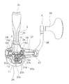
図1に示すように、制動レバー17は、第1軸Xと食い違う第2軸Y方向にリール本体2の脚部2bに装着された支持軸33によりリール本体2に第2軸Y回りに揺動自在に支持される。支持軸33は、図3に示すように、蓋部材2dをリールボディ2aに装着するための鍔付き軸状のナット部材である。支持軸33は、蓋部材2d側から挿入されたねじ部材33aに螺合してリール本体2に固定される。また、前述したように、制動レバー17は、ばね部材19により竿装着部2cと離反する方向に付勢される。
<Configuration of braking lever>
As shown in FIG. 1, the brake lever 17 is swung around the second axis Y by the support shaft 33 attached to the leg 2b of the reel body 2 in the second axis Y direction, which is different from the first axis X. It is supported movably. As shown in FIG. 3, the support shaft 33 is a hooked shaft-like nut member for mounting the lid member 2d on the reel body 2a. The support shaft 33 is fixed to the reel body 2 by screwing into a screw member 33a inserted from the lid member 2d side. Further, as described above, the brake lever 17 is urged by the spring member 19 in a direction away from the rod mounting portion 2c.

脚部2bの前面には、前述したように装着溝2eが形成され、装着溝2eには、シート部材18が装着される。シート部材18は、制動レバー17を支持する支持軸33により装着溝2eに対して抜け止めされる。   As described above, the mounting groove 2e is formed on the front surface of the leg portion 2b, and the seat member 18 is mounted in the mounting groove 2e. The sheet member 18 is prevented from coming off from the mounting groove 2 e by the support shaft 33 that supports the brake lever 17.

制動レバー17は、図1に一点鎖線で示す所定制動位置と、二点鎖線で示す制動解除位置より竿装着部2cに接近した制動位置と、の間で揺動自在にリール本体2に取り付けられる。なお、制動レバー17は、通常は、ばね部材19及び所定制動部21の機構により、図1に実線で示す制動解除位置と一点鎖線で示す所定制動位置とのいずれかに保持される。   The braking lever 17 is attached to the reel body 2 so as to be swingable between a predetermined braking position indicated by a one-dot chain line in FIG. 1 and a braking position closer to the saddle mounting portion 2c than a braking release position indicated by a two-dot chain line. . The brake lever 17 is normally held at either the brake release position indicated by the solid line in FIG. 1 or the predetermined brake position indicated by the alternate long and short dash line by the mechanism of the spring member 19 and the predetermined brake portion 21.

制動レバー17は、制動操作するための操作部17aと、脚部2bの装着溝2eに支持軸33により第2軸Y回りに揺動自在に支持される装着部17bと、装着部17bから延び制動部16に制動作用する制動作用部17cと、を備えている。   The braking lever 17 extends from the mounting portion 17b, an operating portion 17a for performing a braking operation, a mounting portion 17b supported by the mounting groove 2e of the leg portion 2b so as to be swingable around the second axis Y by the support shaft 33, and the mounting portion 17b. And a braking action portion 17c for braking the braking portion 16.

操作部17aは、例えば、アルミニウム合金製の部材であり、鍛造により製造される。操作部17aは、装着部17bに複数(例えば2本)の固定部材(例えばボルト部材)90により装着部17bに着脱自在に連結される。操作部17aは、装着部17bへの連結部分から竿装着部2cに沿ってベールアーム9の外方付近まで前方に延びた後、径方向外方と前方とに分岐して延び、さらに径方向外方に分岐した先端が前方に向けて湾曲した形状である。操作部17aの前方に湾曲した形状の部分が引き込み操作部17dである。引き込み操作部17dは、例えば、釣り竿を持つ手(例えば左手)の人差し指で引き込み操作して操作力に応じてロータ3を制動する際に使用される。また、装着部17bから前方に延びる部分が第1押し込み操作部17eであり、装着部17bに連結される部分が第2押し込み操作部17fである。第1押し込み操作部17e及び第2押し込み操作部17fは、所定制動部21を動作させるために使用される。第1押し込み操作部17eは、釣り竿を持つ手の人差し指で押し込み操作する際に使用される。第2押し込み操作部17fは、釣り竿を持つ手の中指で押し込み操作する際に使用される。   The operation unit 17a is, for example, an aluminum alloy member and is manufactured by forging. The operation portion 17a is detachably connected to the mounting portion 17b by a plurality of (for example, two) fixing members (for example, bolt members) 90 to the mounting portion 17b. The operating portion 17a extends forward from the connecting portion to the mounting portion 17b to the vicinity of the outer side of the bail arm 9 along the saddle mounting portion 2c, and then branches and extends radially outward and forward. The tip branched outward is curved forward. A portion having a curved shape in front of the operation portion 17a is a pull-in operation portion 17d. The pull-in operation unit 17d is used, for example, when the rotor 3 is braked according to an operation force by performing a pull-in operation with an index finger of a hand holding a fishing rod (for example, a left hand). Further, a portion extending forward from the mounting portion 17b is a first push operation portion 17e, and a portion connected to the mounting portion 17b is a second push operation portion 17f. The first pushing operation unit 17e and the second pushing operation unit 17f are used for operating the predetermined braking unit 21. The first push operation unit 17e is used when a push operation is performed with an index finger of a hand holding a fishing rod. The second push operation unit 17f is used when a push operation is performed with the middle finger of a hand holding a fishing rod.

第2押し込み操作部17fには、図3に示すように、金属薄板材をプレス成形により折り曲げて作成された銘版91が着脱自在に装着される。銘版91は、Γ字形状の断面を有し、その上面91aは、竿装着部2cに対向して配置され、断面視僅かに上方に凸に湾曲して形成される。銘版91は、中指の背で第2押し込み操作部17fを押し込み操作するとき、指への当たりを良くするとともに外観の意匠を良好にするために設けられる。   As shown in FIG. 3, a name plate 91 formed by bending a thin metal plate material by press molding is detachably attached to the second pushing operation portion 17f. The inscription plate 91 has a Γ-shaped cross section, and the upper surface 91a thereof is disposed so as to face the saddle mounting portion 2c, and is formed to be slightly convexly curved upward in a sectional view. The name plate 91 is provided in order to improve the appearance of the appearance while improving the contact with the finger when the second pressing operation portion 17f is pressed with the back of the middle finger.

引き込み操作部17dを用いた引き込み操作により、制動レバー17は、実線で示す制動解除位置から二点鎖線で示す竿装着部2cに接近した制動位置に向けて揺動する。また、第1押し込み操作部17e又は第2押し込み操作部17fを用いた押し込み操作により、制動レバー17は、実線で示す制動解除位置から一点鎖線で示す竿装着部2cから離反した所定制動位置に向け揺動する。   By the pull-in operation using the pull-in operation unit 17d, the brake lever 17 swings from the brake release position indicated by the solid line toward the brake position approaching the rod mounting part 2c indicated by the two-dot chain line. Further, by the pushing operation using the first pushing operation portion 17e or the second pushing operation portion 17f, the braking lever 17 is directed from the braking release position indicated by the solid line to the predetermined braking position separated from the rod mounting portion 2c indicated by the alternate long and short dash line. Swing.

装着部17b及び制動作用部17cは、C字状に湾曲して一体形成された、例えば、ステンレス合金製の板状の部材である。装着部17bは、シート部材18内に配置されてリール本体2の脚部2bには接触しないようになっている。これにより、マグネシウム合金製のリール本体2の電解腐食を防止できる。装着部17bには、支持軸33が嵌合する嵌合孔17hが形成される。   The mounting portion 17b and the braking action portion 17c are plate-like members made of, for example, stainless steel, which are integrally formed by bending in a C shape. The mounting portion 17b is arranged in the sheet member 18 so as not to contact the leg portion 2b of the reel body 2. Thereby, electrolytic corrosion of the reel body 2 made of magnesium alloy can be prevented. A fitting hole 17h into which the support shaft 33 is fitted is formed in the mounting portion 17b.

制動作用部17cの先端は、制動円筒41の内周側に対向して配置され、図4に示すように、その先端に制動円筒41の内周面に接触可能な制動シュー34が着脱自在に取り付けられる。また、制動作用部17cの制動シュー34の取付部分の後方には、所定制動部21の後述するレバー部材27の先端が係合する概ね楕円形の係止孔17iに係合する。   The distal end of the braking action portion 17c is arranged to face the inner peripheral side of the braking cylinder 41, and a braking shoe 34 that can contact the inner peripheral surface of the braking cylinder 41 is detachable at the distal end as shown in FIG. It is attached. Further, behind the attachment portion of the braking shoe 34 of the braking action portion 17c, it engages with a substantially elliptical locking hole 17i with which a tip of a lever member 27 described later of the predetermined braking portion 21 is engaged.

制動シュー34は、たとえばポリアミド系合成樹脂やポリアセタールなどの弾性を有する合成樹脂製である。制動シュー34は、図に示すように、制動レバー17の揺動により制動円筒41を径方向外方に押圧する。 The brake shoe 34 is made of, for example, a synthetic resin having elasticity, such as a polyamide-based synthetic resin or polyacetal. As shown in FIG. 4 , the brake shoe 34 presses the brake cylinder 41 radially outward by the swing of the brake lever 17.

制動レバー17は、操作されていないときは、ばね部材19により付勢されて、図1に実線で示すように、制動解除位置に配置されて制動シュー34が制動円筒41から離反する。   When the brake lever 17 is not operated, the brake member 17 is urged by the spring member 19, and is disposed at the brake release position so that the brake shoe 34 is separated from the brake cylinder 41 as shown by a solid line in FIG. 1.

ばね部材19は、シート部材18のばね筒部18aに収容され、装着部17bとリール本体2の脚部2bとの間に圧縮状態で配置される。ばね部材19は、制動レバー17を制動解除側に向けて図1反時計回りに付勢する。これにより、制動状態から制動レバー17から手を離すと、ロータ3は制動解除状態になる。   The spring member 19 is accommodated in the spring cylinder portion 18 a of the sheet member 18, and is disposed in a compressed state between the mounting portion 17 b and the leg portion 2 b of the reel body 2. The spring member 19 biases the brake lever 17 counterclockwise in FIG. 1 toward the brake release side. As a result, when the hand is released from the braking lever 17 from the braking state, the rotor 3 enters the braking release state.

また、制動レバー17は、制動解除状態と所定制動状態とに切り換える操作を行うためにも使用される。制動作用部17cには、前述したように、長円形の係止孔17iが形成される。   The brake lever 17 is also used for switching between a brake release state and a predetermined brake state. As described above, the oval locking hole 17i is formed in the braking action portion 17c.

<所定制動部の構成>
所定制動部21は、図3及び図4に示すように、制動レバー17と連動して揺動するレバー部材27と、トグルばね28と、摩擦部材29と、摩擦リング30と、を有する。トグルばね28は、レバー部材27を制動解除位置と所定制動位置とで保持する。摩擦部材29は、筒状部材40に相対回転可能に装着され筒状部材40に摩擦係合する。摩擦リング30は、たとえばOリングからなり、摩擦部材29を筒状部材40に摩擦係合させるために2つの環状溝40dにそれぞれ装着される。
<Configuration of the predetermined braking unit>
As shown in FIGS. 3 and 4, the predetermined braking unit 21 includes a lever member 27 that swings in conjunction with the braking lever 17, a toggle spring 28, a friction member 29, and a friction ring 30. The toggle spring 28 holds the lever member 27 at the braking release position and the predetermined braking position. The friction member 29 is attached to the cylindrical member 40 so as to be relatively rotatable, and is frictionally engaged with the cylindrical member 40. The friction ring 30 is formed of, for example, an O-ring, and is attached to each of the two annular grooves 40 d in order to frictionally engage the friction member 29 with the tubular member 40.

レバー部材27は、図3に示すように、第1取付部材25の後面にねじ込み固定されスプール軸8と平行に配置された揺動軸27aに揺動自在に装着される。レバー部材27の基端から揺動中心までの距離は、先端から揺動中心までの距離より2倍以上長い。レバー部材27の先端は、係止孔17iに係止されており、レバー部材27は、制動レバー17と連動して制動解除位置と所定制動位置との間で揺動する。レバー部材27には、係止爪70が揺動自在に装着される。トグルばね28は、レバー部材27の基端に係止される。   As shown in FIG. 3, the lever member 27 is swingably mounted on a swing shaft 27 a that is screwed and fixed to the rear surface of the first mounting member 25 and is disposed in parallel with the spool shaft 8. The distance from the base end of the lever member 27 to the swing center is at least twice as long as the distance from the tip to the swing center. The distal end of the lever member 27 is locked in the locking hole 17i, and the lever member 27 swings between the brake release position and the predetermined brake position in conjunction with the brake lever 17. A locking claw 70 is swingably attached to the lever member 27. The toggle spring 28 is locked to the base end of the lever member 27.

ここで、レバー部材27が制動解除位置にあるときは、レバー部材27の基端はトグルばね28により付勢されて係止孔17iの上面に接触し、レバー部材27が所定制動位置にあるときは、レバー部材27の基端は係止孔17iの下面に接触する。レバー部材27の中間部には、係止爪70が揺動自在に装着される。係止爪70は、基端にコイルばね71の一端が係止され、先端が突出する方向に付勢される。コイルばね71の他端はレバー部材27の揺動軸に係止される。このように係止爪70をレバー部材27に揺動自在に装着し、かつコイルばね71で先端を突出する方向に付勢することにより、摩擦部材29を確実に回り止めできる。すなわち、所定制動位置にレバー部材27が揺動したとき、係止爪70先端と後述する摩擦部材29の鋸歯部29aとの回転位相が合わずに、係止爪70の先端が鋸歯部29aの突出部分に接触してもショックを吸収して摩擦部材29を確実に回り止めすることができる。 Here, when the lever member 27 is in the braking release position, the base end of the lever member 27 is urged by the toggle spring 28 to contact the upper surface of the locking hole 17i, and the lever member 27 is in the predetermined braking position. The base end of the lever member 27 contacts the lower surface of the locking hole 17i. A locking claw 70 is swingably attached to the intermediate portion of the lever member 27. The locking claw 70 is biased in a direction in which one end of the coil spring 71 is locked to the base end and the tip protrudes. The other end of the coil spring 71 is locked to the swing shaft of the lever member 27. Thus, by attaching the latching claw 70 to the lever member 27 in a swingable manner and biasing it in a direction in which the tip is projected by the coil spring 71, the friction member 29 can be reliably prevented from rotating. That is, when the lever member 27 swings to a predetermined braking position, the rotational phase of the engaging claw 70 tip and the sawtooth portion 29a of the friction member 29 described later does not match, and the leading end of the engaging claw 70 is the sawtooth portion 29a. Even if it contacts the protruding portion, the shock can be absorbed and the friction member 29 can be reliably prevented from rotating.

図4に示すように、摩擦部材29は、筒状の部材であり、筒状部材40の外周に回転自在に装着される。摩擦部材29の一端(図4右端)内周面には、係止爪70の先端に係合する鋸歯部29aが径方向内方に突出して形成される。鋸歯部29aは、レバー部材27が所定制動位置にあるとき、係止爪70に係合して摩擦部材29の糸繰り出し方向の回転を禁止するために設けられる。摩擦部材29の他端(図4左端)と筒状部材40の円板部40cの外側面との間には、第1座金72が配置される。第1座金72は、C字状に湾曲して形成された止め輪74により抜け止めされる。止め輪74は、摩擦部材29の他端内周面に形成された環状溝29cに装着される。また、鋸歯部29aと筒状部材40との間には第2座金75が装着される。第1座金72及び第2座金75は、摩擦部材29の軸方向の取り付け寸法を調節して摩擦部材29ががたつかないように設けられる。   As shown in FIG. 4, the friction member 29 is a cylindrical member and is rotatably mounted on the outer periphery of the cylindrical member 40. On the inner peripheral surface of one end (the right end in FIG. 4) of the friction member 29, a sawtooth portion 29 a that engages with the tip of the locking claw 70 is formed so as to protrude radially inward. The sawtooth portion 29a is provided to engage the locking claw 70 and inhibit the friction member 29 from rotating in the yarn unwinding direction when the lever member 27 is in the predetermined braking position. A first washer 72 is disposed between the other end (the left end in FIG. 4) of the friction member 29 and the outer surface of the disc portion 40 c of the cylindrical member 40. The first washer 72 is retained by a retaining ring 74 that is curved in a C shape. The retaining ring 74 is attached to an annular groove 29 c formed on the inner peripheral surface of the other end of the friction member 29. A second washer 75 is mounted between the sawtooth portion 29 a and the tubular member 40. The first washer 72 and the second washer 75 are provided so that the friction member 29 does not rattle by adjusting the axial mounting dimension of the friction member 29.

このような構成の摩擦部材29では、レバー部材27が所定制動位置に配置され係止爪70が鋸歯部29aに係合したとき、摩擦部材29が摩擦リング30の作用により筒状部材40に対して摩擦摺動する。   In the friction member 29 having such a configuration, when the lever member 27 is disposed at a predetermined braking position and the locking claw 70 is engaged with the sawtooth portion 29 a, the friction member 29 acts on the cylindrical member 40 by the action of the friction ring 30. Friction sliding.

ここでは、制動レバー17を所定制動位置に押し込み操作すると、それに連動してレバー部材27も制動解除位置から所定制動位置に揺動する。この結果、係止爪70が摩擦部材29の鋸歯部29aに係合し、ロータ3の糸繰り出し方向の回転を所定制動状態で制動する。   Here, when the brake lever 17 is pushed into the predetermined braking position, the lever member 27 swings from the braking release position to the predetermined braking position in conjunction therewith. As a result, the locking claw 70 engages with the sawtooth portion 29a of the friction member 29, and brakes the rotation of the rotor 3 in the yarn unwinding direction in a predetermined braking state.

トグルばね28は、レバー部材27を揺動方向の両方向に振り分けて付勢して制動レバー17を所定制動位置と制動解除位置とに付勢し、その姿勢を保持することができる。トグルばね28は、レバー部材27の基端に装着された捩じりコイルばねである。トグルばね28は、一端がレバー部材27の基端に係止され、他端がリールボディ2aの前端面に係止される。トグルばね28によって、レバー部材27が制動解除位置と所定制動位置とで保持され、さらに制動レバー17が制動解除位置と所定制動位置とに保持される。   The toggle spring 28 can urge the brake member 17 to a predetermined brake position and a brake release position by allocating and urging the lever member 27 in both directions of the swinging direction, and can maintain the posture. The toggle spring 28 is a torsion coil spring attached to the base end of the lever member 27. One end of the toggle spring 28 is locked to the base end of the lever member 27, and the other end is locked to the front end surface of the reel body 2a. The toggle spring 28 holds the lever member 27 at the brake release position and the predetermined brake position, and further holds the brake lever 17 at the brake release position and the predetermined brake position.

<リールの動作及び操作>
キャスティング時にはベールアーム9を糸開放姿勢側に倒し、キャスティングすることにより、スプール4の外周から釣り糸が繰り出される。糸巻取時には、ハンドル1を糸巻き取り方向に回転させると、ベールアーム9が図示しない戻し機構により糸巻き取り姿勢に戻る。ハンドル1の回転力は、駆動軸10、駆動ギア11を介してピニオンギア12に伝達される。ピニオンギア12に伝達された回転力は、ピニオンギア12の前部12a及び回転制御機構7を介してロータ3に伝達される。このときロータ3は糸巻き取り方向に回転するので、第1ワンウェイクラッチ32のラチェット爪43がばね部材44により噛み合い解除位置側に付勢され、ラチェット爪43とラチェットホイール42との噛み合いが解除され、この回転力は筒状部材40には伝達されない。ピニオンギア12が回転すると、スプール軸8が前後方向に往復移動する。
<Reel operation and operation>
At the time of casting, the fishing line is fed out from the outer periphery of the spool 4 by tilting the bail arm 9 toward the line releasing posture and casting. At the time of winding the yarn, if the handle 1 is rotated in the yarn winding direction, the bail arm 9 returns to the yarn winding posture by a return mechanism (not shown). The rotational force of the handle 1 is transmitted to the pinion gear 12 via the drive shaft 10 and the drive gear 11. The rotational force transmitted to the pinion gear 12 is transmitted to the rotor 3 via the front portion 12 a of the pinion gear 12 and the rotation control mechanism 7. At this time, since the rotor 3 rotates in the yarn winding direction, the ratchet pawl 43 of the first one-way clutch 32 is urged toward the meshing release position by the spring member 44, and the meshing between the ratchet pawl 43 and the ratchet wheel 42 is released, This rotational force is not transmitted to the cylindrical member 40. When the pinion gear 12 rotates, the spool shaft 8 reciprocates in the front-rear direction.

制動レバー17を操作しなければ、制動レバー17はばね部材19及び所定制動部21の作用により押圧され制動解除位置または所定制動位置に配置される。   If the brake lever 17 is not operated, the brake lever 17 is pressed by the action of the spring member 19 and the predetermined brake portion 21 and is disposed at the brake release position or the predetermined brake position.

ロータ3を逆転させて魚とやりとりする時には、制動レバー17の引き込み操作部17dをたとえば人差し指により竿装着部2c側に引き込み操作して制動力を調整する。   When exchanging with the fish by reversing the rotor 3, the pulling operation portion 17d of the brake lever 17 is pulled toward the rod mounting portion 2c side with, for example, an index finger to adjust the braking force.

釣り糸が魚により引かれてロータ3が糸繰り出し方向に逆転すると、ロータ3の回転力が第1ワンウェイクラッチ32を介して筒状部材40に伝達され、さらに制動円筒41に伝達され、ロータ制動機構6が制動可能な状態になる。糸繰り出し方向にロータ3が回転するとき、第1ワンウェイクラッチ32では、ラチェット爪43がばね部材44により付勢されて噛み合い位置側に揺動する。ラチェット爪43が噛み合い位置に揺動すると、ラチェットホイール42のラチェット歯42bがラチェット爪43の先端の爪部43aに衝突し、ラチェットホイール42が振動する。しかし、この振動は防振部材45により吸収され、ロータ3に伝達されない。このため、釣り人に不快感を与えにくくなるとともに、ラチェット歯42bやラチェット爪43に悪影響を与えにくくなる。   When the fishing line is pulled by the fish and the rotor 3 is reversed in the line-feeding direction, the rotational force of the rotor 3 is transmitted to the cylindrical member 40 via the first one-way clutch 32 and further transmitted to the brake cylinder 41, and the rotor braking mechanism 6 is ready to be braked. When the rotor 3 rotates in the yarn feeding direction, in the first one-way clutch 32, the ratchet pawl 43 is urged by the spring member 44 and swings to the meshing position side. When the ratchet pawl 43 swings to the meshing position, the ratchet teeth 42b of the ratchet wheel 42 collide with the pawl portion 43a at the tip of the ratchet pawl 43, and the ratchet wheel 42 vibrates. However, this vibration is absorbed by the vibration isolation member 45 and is not transmitted to the rotor 3. For this reason, it becomes difficult to give discomfort to the angler, and it is difficult to adversely affect the ratchet teeth 42b and the ratchet pawl 43.

また、ロータ3が糸繰り出し方向に回転すると、その回転は、前述したように回転制御機構7によって遮断され、ピニオンギア12には伝達されない。このため、ロータ3が糸繰り出し方向に回転してもハンドル1が糸繰り出し方向に回転しない。   When the rotor 3 rotates in the yarn feeding direction, the rotation is blocked by the rotation control mechanism 7 as described above and is not transmitted to the pinion gear 12. For this reason, even if the rotor 3 rotates in the yarn unwinding direction, the handle 1 does not rotate in the yarn unwinding direction.

ラチェット歯42bがラチェット爪43に噛み合うと、ロータ3の回転が筒状部材40伝達され、制動円筒41がロータ3と一体で回転する。制動レバー17の引き込み操作部17dを竿装着部2cに接近する方向に引き込み操作すると、たとえ制動レバー17が所定制動位置にあっても、レバー部材27が制動解除位置側に揺動する。この結果、所定制動部21による所定制動状態が一旦解除される。このとき、トグルばね28がレバー部材27の揺動により反転し、レバー部材27が制動解除位置側に付勢され、レバー部材27が制動解除位置で保持される。 When the ratchet teeth 42 b mesh with the ratchet pawl 43, the rotation of the rotor 3 is transmitted to the tubular member 40 , and the brake cylinder 41 rotates integrally with the rotor 3. When the pulling operation portion 17d of the brake lever 17 is pulled in a direction approaching the rod mounting portion 2c, the lever member 27 swings to the brake release position side even if the brake lever 17 is at the predetermined braking position. As a result, the predetermined braking state by the predetermined braking unit 21 is once released. At this time, the toggle spring 28 is reversed by the swing of the lever member 27, the lever member 27 is biased toward the brake release position, and the lever member 27 is held at the brake release position.

この状態でさらに制動レバー17を竿装着部2cに接近する方向に操作すると、制動レバー17の制動シュー34が制動円筒41の内周面を径方向外方に強く押圧する。この制動力は制動レバー17に加える力を加減することにより調整でき、ロータ3の逆転量を任意に調整できる。この結果、制動レバー17の操作力に応じた制動力がロータ3に付与される。このように、所定制動状態の解除を忘れても、制動レバー17を引き込み操作するだけで、所定制動状態を解除できる。   In this state, when the brake lever 17 is further operated in a direction approaching the rod mounting portion 2c, the brake shoe 34 of the brake lever 17 strongly presses the inner peripheral surface of the brake cylinder 41 radially outward. This braking force can be adjusted by adjusting the force applied to the braking lever 17, and the amount of reverse rotation of the rotor 3 can be adjusted arbitrarily. As a result, a braking force corresponding to the operating force of the braking lever 17 is applied to the rotor 3. As described above, even if the user forgets to release the predetermined braking state, the predetermined braking state can be canceled by merely pulling the brake lever 17.

釣り場を移動する時やリールを収納する時には、引き込み操作部17dから手を離し第1押し込み操作部17e又は第2押し込み操作部17fを竿装着部2cから離反する方向に押し込み操作する。すると、図4に示すように、レバー部材27が制動解除位置から所定制動位置に揺動し、トグルばね28によりその位置で保持される。この結果、係止爪70が摩擦部材29の鋸歯部29aに係合して摩擦部材29の回転が阻止され、ロータ3の逆転が阻止される。このため、ロータ3の回転が回転制御機構7によって自由回転状態になっても、ロータ3が糸繰り出し方向に回転しなくなり、釣り糸が仕掛けの自重によって繰り出されることはない。   When the fishing ground is moved or the reel is stored, the hand is released from the pull-in operation portion 17d, and the first push-in operation portion 17e or the second push-in operation portion 17f is pushed in the direction away from the rod mounting portion 2c. Then, as shown in FIG. 4, the lever member 27 swings from the braking release position to the predetermined braking position and is held at that position by the toggle spring 28. As a result, the engaging claw 70 engages with the sawtooth portion 29a of the friction member 29, and the rotation of the friction member 29 is prevented, and the reverse rotation of the rotor 3 is prevented. For this reason, even if the rotation of the rotor 3 is brought into the free rotation state by the rotation control mechanism 7, the rotor 3 does not rotate in the line feeding direction, and the fishing line is not fed out by its own weight.

このときの制動力は、摩擦部材29と筒状部材40との間に装着された摩擦リング30の弾性力によって定められる。このため、移動途中にハンドル1に何かが当たってもハンドル1が回らない程度に強い所定制動力を得やすくなり、釣り場の移動途中に糸ふけが生じない程度に強く所定制動力を設定できる。また、摩擦部材29と筒状部材40との相対回転により制動するので、制動力が変動しにくくなり安定する。   The braking force at this time is determined by the elastic force of the friction ring 30 mounted between the friction member 29 and the cylindrical member 40. For this reason, it becomes easy to obtain a predetermined braking force that is strong enough that the handle 1 does not rotate even if something hits the handle 1 during the movement, and the predetermined braking force can be set so strong that no dandruff occurs during the movement of the fishing ground. . Further, since braking is performed by the relative rotation between the friction member 29 and the cylindrical member 40, the braking force is less likely to fluctuate and is stabilized.

さらに、仕掛けの垂らし長さを変更するためや、魚に当たりがあった時に魚に仕掛けを確実に食い込ませるために、ロータ3を所定制動状態から制動解除状態にしたい場合には、制動レバー17を僅かに竿装着部2cに接近する方向に操作すればよい。すると、前述したように、制動レバー17によりレバー部材27が制動解除位置に揺動して所定制動状態が一旦解除される。   Further, in order to change the hanging length of the device, or to make the fish bite into the device when it hits the fish, when the rotor 3 is desired to be released from the predetermined braking state, the braking lever 17 is What is necessary is just to operate in the direction which approaches the heel mounting part 2c slightly. Then, as described above, the lever member 27 is swung to the brake release position by the brake lever 17 and the predetermined brake state is once released.

<他の実施形態>
以上、本発明の一実施形態について説明したが、本発明は上記実施形態に限定されるものではなく、発明の要旨を逸脱しない範囲で種々の変更が可能である。特に、本明細書に書かれた複数の実施形態及び変形例は必要に応じて任意に組合せ可能である。
<Other embodiments>
As mentioned above, although one Embodiment of this invention was described, this invention is not limited to the said embodiment, A various change is possible in the range which does not deviate from the summary of invention. In particular, a plurality of embodiments and modifications described in this specification can be arbitrarily combined as necessary.

(a)上記実施形態では、回転制御機構7をピニオンギア12とロータ3の間に配置したが、本発明はこれに限定されない。たとえば、駆動軸と駆動ギアの間、又は駆動軸とハンドルの間に回転制御機構を設けてもよい。これらの場合には、ロータが逆転すると、スプールも前後に往復移動する。   (A) In the above embodiment, the rotation control mechanism 7 is disposed between the pinion gear 12 and the rotor 3, but the present invention is not limited to this. For example, a rotation control mechanism may be provided between the drive shaft and the drive gear or between the drive shaft and the handle. In these cases, when the rotor reverses, the spool also reciprocates back and forth.

(b)上記実施形態では、回転制御機構7としてローラ収容凹部53が第1筒部50に設けられる外輪遊転型のローラクラッチを例示したが、ローラ収容凹部が第2筒部に設けられる内輪遊転型のローラクラッチを用いてもよい。たとえば、ハンドルと駆動軸との間に回転制御機構を設ける場合、このような内輪遊転型の構造を採用してもよい。   (B) In the above embodiment, the outer ring idle type roller clutch in which the roller accommodating recess 53 is provided in the first cylindrical portion 50 is exemplified as the rotation control mechanism 7, but the inner ring in which the roller accommodating recess is provided in the second cylindrical portion. An idle type roller clutch may be used. For example, when a rotation control mechanism is provided between the handle and the drive shaft, such an inner ring idle structure may be adopted.

(c)上記実施形態では、複数の一例としてローラ52及びローラ収容凹部53の数を6個としたが、本発明はこれに限定されない。ローラ及びローラ収容凹部の数は、複数であればどのような数でもよい。ただし、スペースの関係から、ローラ及びローラ収容凹部の数は、4個から12個の範囲であることが好ましい。   (C) In the above embodiment, the number of the rollers 52 and the roller accommodating recesses 53 is six as an example, but the present invention is not limited to this. The number of rollers and roller receiving recesses may be any number as long as it is plural. However, in view of space, the number of rollers and roller receiving recesses is preferably in the range of 4 to 12.

(d)上記実施形態では、第2筒部51に設けられる係合凸部51c及びボス部3eの貫通孔3fに設けられる係合凹部3iは6個であったが、本発明はこれに限定されず、これらは少なくとも一つあればよい。また、係合凸部を貫通孔に設け、係合凹部を第1筒部に設けてもよい。   (D) In the above embodiment, the number of the engagement convex portions 51c provided in the second cylindrical portion 51 and the number of the engagement concave portions 3i provided in the through holes 3f of the boss portion 3e are six, but the present invention is limited to this. However, at least one of these is sufficient. Further, the engaging convex portion may be provided in the through hole, and the engaging concave portion may be provided in the first tube portion.

(e)上記実施形態では、切換部材56及び付勢部材57を、ばね性を有する金属板材で構成したが、本発明はこれに限定されない。例えば、切換部材56及び付勢部材57の少なくともいずれかを、ばね性を有する金属線材によって構成してもよい。例えば、切換部材56をばね部材44と同様な構成にしてもよい。この場合、摩擦抵抗が小さくなり、ロータ3の回転時の巻き取り方向の回転抵抗が小さくなる。また、弾性を有する金属製又は合成樹脂製の弾性部材によって構成してもよい。   (E) In the above embodiment, the switching member 56 and the urging member 57 are made of a metal plate material having a spring property, but the present invention is not limited to this. For example, at least one of the switching member 56 and the urging member 57 may be made of a metal wire having springiness. For example, the switching member 56 may be configured similarly to the spring member 44. In this case, the frictional resistance is reduced, and the rotational resistance in the winding direction during rotation of the rotor 3 is reduced. Moreover, you may comprise by the elastic member made from a metal or a synthetic resin which has elasticity.

<特徴>
上記実施形態は、下記のように表現可能である。
<Features>
The above embodiment can be expressed as follows.

(A)スピニングリール100は、釣り糸を前方に繰り出し可能なリールであって、ハンドル1と、リール本体2と、スプール軸と、糸巻用のスプール4と、ロータ3と、回転伝達機構5と、回転制御機構7と、を備える。リール本体2は、ハンドル1が側部に回転自在に装着されるものである。スプール軸8は、リール本体2に前後移動自在に支持される。スプール4は、スプール軸8の先端に設けられる。ロータ3は、スプール軸8回りに回転自在に設けられ、スプール4に釣り糸を巻き付けるためのものである。回転伝達機構5は、ハンドル1が一体的に回転可能に連結される駆動軸10、駆動軸10と一体的に回転可能な駆動ギア11、及びスプール軸8の外周側に配置され、駆動ギア11に噛み合うピニオンギア12、を有する。回転制御機構7は、ハンドル1とロータ3との間に配置され、ハンドル1がリール本体に対して糸巻取方向に回転すると、ハンドル1からの回転をロータ3に伝達し、ロータ3がリール本体に対して回転すると、ロータ3の回転をハンドルに伝達せず、かつロータ3を自由回転可能に制御する。 (A) The spinning reel 100 is a reel capable of feeding a fishing line forward, and includes a handle 1, a reel body 2, a spool shaft 8 , a spool 4 for spooling, a rotor 3, and a rotation transmission mechanism 5. And a rotation control mechanism 7. The reel body 2 has a handle 1 mounted rotatably on the side. The spool shaft 8 is supported by the reel body 2 so as to be movable back and forth. The spool 4 is provided at the tip of the spool shaft 8. The rotor 3 is provided so as to be rotatable around the spool shaft 8 and is used for winding fishing line around the spool 4. The rotation transmission mechanism 5 is disposed on the outer peripheral side of the drive shaft 10 to which the handle 1 is integrally connected to be rotatable, the drive gear 11 that can rotate integrally with the drive shaft 10, and the spool shaft 8. The pinion gear 12 meshes with the pinion gear 12. The rotation control mechanism 7 is disposed between the handle 1 and the rotor 3. When the handle 1 rotates in the yarn winding direction with respect to the reel body 2 , the rotation from the handle 1 is transmitted to the rotor 3, and the rotor 3 is reeled. When rotating with respect to the main body 2 , the rotation of the rotor 3 is not transmitted to the handle, and the rotor 3 is controlled to be freely rotatable.

このスピニングリール100では、ハンドル1が回転すると、その回転が回転伝達機構5及び回転制御機構7を介してロータ3に伝達され、ロータ3が回転する。一方、魚が仕掛けに掛かるなどによってロータ3が回転すると、その回転は、回転制御機構7によって遮断され、ハンドル1には伝達されない。ここでは、回転制御機構7を設けてロータ3からハンドル1への回転を遮断しつつハンドル1からの回転をロータ3に伝達できる。このため、操作部材を操作することなく、いずれの方向でもハンドル1の回転をロータ3に常時伝達できるようにすることになる。   In the spinning reel 100, when the handle 1 rotates, the rotation is transmitted to the rotor 3 through the rotation transmission mechanism 5 and the rotation control mechanism 7, and the rotor 3 rotates. On the other hand, when the rotor 3 rotates due to, for example, a fish being caught, the rotation is blocked by the rotation control mechanism 7 and is not transmitted to the handle 1. Here, the rotation control mechanism 7 is provided to transmit the rotation from the handle 1 to the rotor 3 while blocking the rotation from the rotor 3 to the handle 1. Therefore, the rotation of the handle 1 can be always transmitted to the rotor 3 in any direction without operating the operation member.

(B)回転制御機構7は、第1筒部50と、第2筒部51と、複数のローラ52と、複数のローラ収容凹部53と、切換機構54と、を有してもよい。第2筒部51は、第1筒部50と同心かつ径方向の異なる位置に配置される。複数のローラ52は、第1筒部
50と第2筒部51との間に周方向に間隔を隔てて配置される。複数のローラ収容凹部53は、第1筒部50のローラ52が配置される位置に凹んで設けられ、ローラ52との間に隙間が形成される自由回転位置53a、並びに自由回転位置53aの両側に設けられローラ52が食い込む回転伝達位置53b、を有する。切換機構54は、第1筒部50が回転すると、ローラ52を回転伝達位置53bに移動させ、第2筒部51が回転するとローラ52を自由回転位置53aに維持する。
(B) The rotation control mechanism 7 may include a first cylinder part 50, a second cylinder part 51, a plurality of rollers 52, a plurality of roller accommodating recesses 53, and a switching mechanism 54. The second cylinder part 51 is arranged at a position that is concentric with the first cylinder part 50 and is different in the radial direction. The plurality of rollers 52 are disposed between the first tube portion 50 and the second tube portion 51 with a space therebetween in the circumferential direction. The plurality of roller accommodating recesses 53 are provided in a recessed manner at a position where the roller 52 of the first cylindrical portion 50 is disposed, and a free rotation position 53a where a gap is formed between the roller 52 and both sides of the free rotation position 53a. And a rotation transmission position 53b into which the roller 52 bites. The switching mechanism 54 moves the roller 52 to the rotation transmission position 53b when the first cylinder portion 50 rotates, and maintains the roller 52 at the free rotation position 53a when the second cylinder portion 51 rotates.

この場合には、第2筒部51がリール本体に対して回転すると、ローラ52が自由回転位置53aに維持され、第2筒部51だけが回転し、第2筒部51の回転が第1筒部50に伝達されない。それに対して、第1筒部50がリール本体に対して回転すると、ローラ52が回転伝達位置53bに移動し、第1筒部50の回転が第2筒部51に伝達される。ここでは、第1筒部50にハンドル1の回転が伝達され、第2筒部51にロータ3の回転が伝達されるように、第1筒部50及び第2筒部51を配置することによって、操作部材を操作することなく、ハンドル1の回転をロータ3に常時伝達できるようになる。 In this case, when the second cylindrical portion 51 rotates with respect to the reel body 2 , the roller 52 is maintained at the free rotation position 53a, only the second cylindrical portion 51 rotates, and the rotation of the second cylindrical portion 51 is the first. It is not transmitted to one cylinder part 50. On the other hand, when the first cylinder part 50 rotates with respect to the reel body 2 , the roller 52 moves to the rotation transmission position 53 b and the rotation of the first cylinder part 50 is transmitted to the second cylinder part 51. Here, by arranging the first cylinder part 50 and the second cylinder part 51 so that the rotation of the handle 1 is transmitted to the first cylinder part 50 and the rotation of the rotor 3 is transmitted to the second cylinder part 51. The rotation of the handle 1 can always be transmitted to the rotor 3 without operating the operation member.

(C)第1筒部50は、第2筒部51の径方向内側に配置されてもよい。この場合には、ピニオンギア12に連結される第1筒部50が内輪となり、ピニオンギア12の外周側に配置されるロータ3が外輪となる第2筒部51に連結される。このため、回転制御機構7の構成がコンパクトになる。   (C) The first tube portion 50 may be disposed on the radially inner side of the second tube portion 51. In this case, the 1st cylinder part 50 connected with the pinion gear 12 becomes an inner ring | wheel, and the rotor 3 arrange | positioned at the outer peripheral side of the pinion gear 12 is connected with the 2nd cylinder part 51 used as an outer ring | wheel. For this reason, the structure of the rotation control mechanism 7 becomes compact.

(D)回転制御機構7は、ピニオンギア12とロータ3との間に配置されてもよい。この場合には、回転制御機構7がロータ3に連結されるので、ロータ3だけが自由回転状態になり、回転伝達機構5が自由回転状態にならない。このため、回転伝達機構5の自由回転によって生じる空転等の不具合(オシレーティング機構20によるスプール4の前後移動など)が生じにくくなる。   (D) The rotation control mechanism 7 may be disposed between the pinion gear 12 and the rotor 3. In this case, since the rotation control mechanism 7 is connected to the rotor 3, only the rotor 3 is in a free rotation state, and the rotation transmission mechanism 5 is not in a free rotation state. For this reason, problems such as idling caused by the free rotation of the rotation transmission mechanism 5 (such as forward and backward movement of the spool 4 by the oscillating mechanism 20) are less likely to occur.

(E)ピニオンギア12は、第1筒部50に装着され、ロータ3は、第2筒部51に装着されてもよい。この場合には、ピニオンギア12の回転のロータ3への伝達を直接制御できるのでロータ3の回転制御を迅速に行なえる。 (E) The pinion gear 12 may be attached to the first cylinder part 50, and the rotor 3 may be attached to the second cylinder part 51. In this case, quickly perform the rotation control of the rotor 3 can be controlled to transfer our to the rotor 3 of the rotation of the pinion gear 12 directly.

(F)切換機構54は、ローラ52を周方向に間隔を隔てて配置するための間隔保持部材55と、切換部材56と、付勢部材57と、を有してもよい。切換部材56は、間隔保持部材55に連結され、第1筒部50の回転に応じて間隔保持部材55を周方向に移動させ、複数のローラ52を自由回転位置53aから回転伝達位置53bに移動させる。付勢部材57は、間隔保持部材55を介してローラ52を自由回転位置53aに向けて付勢する。この場合には、間隔保持部材55によって複数のローラ52を自由回転位置53aと回転伝達位置53bとに移動させるので、複数のローラ52を同時に移動させることでき、自由回転位置53aから回転伝達位置53bへの切り換えを迅速に行える。 (F) The switching mechanism 54 may include an interval holding member 55 for arranging the rollers 52 at intervals in the circumferential direction, a switching member 56, and an urging member 57. The switching member 56 is connected to the interval holding member 55, moves the interval holding member 55 in the circumferential direction in accordance with the rotation of the first cylindrical portion 50, and moves the plurality of rollers 52 from the free rotation position 53a to the rotation transmission position 53b. Let The urging member 57 urges the roller 52 toward the free rotation position 53a via the interval holding member 55. In this case, the move to a plurality of rollers 52 freely rotatable position 53a by spacing members 55 and the rotation transmission position 53b, it is possible to move the plurality of rollers 52 at the same time, the rotation transmission position from the free rotation position 53a Switching to 53b can be performed quickly.

(G)スピニングリール100は、ロータ3の糸繰り出し方向の回転を制動するための制動レバー17、及び制動レバー17の操作によってロータ3の糸繰り出し方向の回転を制動可能な制動部16、を有するロータ制動機構6をさらに備えてもよい。この場合には、ロータ3が糸繰り出し方向に回転しても、制動レバー17によって、ロータ3の糸繰り出し方向の回転を制動できる。このため、釣り糸の無用な繰り出しを防止できる。また、ロータ3が糸繰り出し方向に回転しても、回転バランスが悪いハンドル1が糸繰り出し方向に回転しない。このため、スピニングリール100の回転バランスが崩れにくい。   (G) The spinning reel 100 includes a brake lever 17 for braking the rotation of the rotor 3 in the yarn take-out direction, and a brake unit 16 capable of braking the rotation of the rotor 3 in the yarn take-out direction by operating the brake lever 17. A rotor braking mechanism 6 may be further provided. In this case, even if the rotor 3 rotates in the yarn feeding direction, the brake lever 17 can brake the rotation of the rotor 3 in the yarn feeding direction. For this reason, unnecessary feeding of the fishing line can be prevented. Further, even if the rotor 3 rotates in the yarn drawing direction, the handle 1 having a poor rotation balance does not rotate in the yarn drawing direction. For this reason, the rotation balance of the spinning reel 100 is not easily lost.

(H)ロータ制動機構6は、ロータ3を所定制動状態と制動解除状態とに切換可能な所定制動部21をさらに有してもよい。この場合には、自由回転状態のロータ3を所定制動できるので、釣り場を移動するときなどに釣り糸の繰り出しを防止できる。   (H) The rotor braking mechanism 6 may further include a predetermined braking unit 21 that can switch the rotor 3 between a predetermined braking state and a braking release state. In this case, since the rotor 3 in the freely rotating state can be braked for a predetermined time, it is possible to prevent the fishing line from being unwound when moving on the fishing ground.

1 ハンドル
2 リール本体
3 ロータ
4 スプール
5 回転伝達機構
6 ロータ制動機構
7 回転制御機構
8 スプール軸
10 駆動軸
11 駆動ギア
12 ピニオンギア
16 制動部
17 制動レバー
21 所定制動部
50 第1筒部
51 第2筒部
52 ローラ
53 ローラ収容凹部
53a 自由回転位置
53b 回転伝達位置
54 切換機構
55 間隔保持部材
56 切換部材
57 付勢部材
DESCRIPTION OF SYMBOLS 1 Handle 2 Reel body 3 Rotor 4 Spool 5 Rotation transmission mechanism 6 Rotor brake mechanism 7 Rotation control mechanism 8 Spool shaft 10 Drive shaft 11 Drive gear 12 Pinion gear 16 Brake part 17 Brake lever 21 Predetermined brake part 50 1st cylinder part 51 1st 2 cylinder part 52 roller 53 roller accommodation recessed part 53a free rotation position 53b rotation transmission position 54 switching mechanism 55 space | interval holding member 56 switching member 57 biasing member

Claims (8)

釣り糸を前方に繰り出し可能なスピニングリールであって、
ハンドルと、
前記ハンドルが側部に回転自在に装着されるリール本体と、
前記リール本体に前後移動自在に支持されたスプール軸と、
前記スプール軸の先端に設けられる糸巻用のスプールと、
前記スプール軸回りに回転自在に設けられ、前記スプールに釣り糸を巻き付けるためのロータと、
前記ハンドルが一体的に回転可能に連結される駆動軸、前記駆動軸と一体的に回転可能な駆動ギア、前記スプール軸の外周側に配置され、前記駆動ギアに噛み合うピニオンギア、を有する回転伝達機構と、
前記ハンドルと前記ロータとの間に配置され、前記ハンドルが前記リール本体に対して回転すると、前記ハンドルからの回転を前記ロータに伝達し、前記ロータが前記リール本体に対して回転すると、前記ロータからの回転を前記ハンドルに伝達せず、かつ前記ロータを自由回転可能に制御する回転制御機構と、
を備えるスピニングリール。
A spinning reel that can feed the fishing line forward,
A handle,
A reel body on which the handle is rotatably mounted on the side;
A spool shaft supported by the reel body so as to be movable back and forth;
A spool for spooling provided at the tip of the spool shaft;
A rotor provided so as to be rotatable around the spool shaft and for winding a fishing line around the spool;
Drive shaft said handle is rotatably connected integrally, said drive shaft and integrally rotatable drive gear is disposed on the outer peripheral side of the spool shaft, rotating with the pinion gear, which meshes with the prior SL drive gear A transmission mechanism;
When the handle is rotated with respect to the reel body, the rotation from the handle is transmitted to the rotor, and when the rotor rotates with respect to the reel body, the rotor is disposed between the handle and the rotor. A rotation control mechanism that does not transmit the rotation from the handle to the handle and controls the rotor to be freely rotatable;
Spinning reel with.
前記回転制御機構は、
第1筒部と、
前記第1筒部と同芯かつ径方向の異なる位置に配置される第2筒部と、
前記第1筒部と前記第2筒部との間に周方向に間隔を隔てて配置される複数のローラと、
前記第1筒部の前記ローラが配置される位置に凹んで設けられ、前記ローラとの間に隙間が形成される自由回転位置、並びに前記自由回転位置の両側に設けられ前記ローラが食い込む回転伝達位置、を有する複数のローラ収容凹部と、
前記リール本体に回転可能に摩擦係合し、前記第1筒部が前記ハンドルによって回転すると、前記ローラを前記回転伝達位置に移動させ、前記第2筒部が静止する前記第1筒部に対して回転すると前記ローラを前記自由回転位置に維持する切換機構と、を有する、請求項1に記載のスピニングリール。
The rotation control mechanism is
A first tube portion;
A second cylindrical portion disposed concentrically with the first cylindrical portion and at a different radial direction;
A plurality of rollers arranged at intervals in the circumferential direction between the first tube portion and the second tube portion;
The first cylindrical portion is recessed at a position where the roller is disposed, and a free rotation position where a gap is formed between the roller and a rotation transmission provided on both sides of the free rotation position. A plurality of roller receiving recesses having a position;
Combined rotatably friction on the reel body and the first cylindrical portion is rotated by said handle to move the roller in the rotation transmission position, relative to the first cylindrical portion and the second cylindrical portion is still having a switching mechanism to maintain the free rotation position said rollers to rotate Te, spinning reel according to claim 1.
前記第1筒部は前記第2筒部の前記径方向内側に配置される、請求項2に記載のスピニングリール。   The spinning reel according to claim 2, wherein the first cylindrical portion is disposed on the radially inner side of the second cylindrical portion. 前記回転制御機構は、前記ピニオンギアと前記ロータとの間に配置される、請求項2又は3に記載のスピニングリール。   The spinning reel according to claim 2 or 3, wherein the rotation control mechanism is disposed between the pinion gear and the rotor. 前記ピニオンギアは、前記第1筒部に一体回転可能に連結され、
前記ロータは、前記第2筒部に一体回転可能に連結される、請求項4に記載のスピニングリール。
The pinion gear is coupled to the first tube portion so as to be integrally rotatable,
The spinning reel according to claim 4, wherein the rotor is coupled to the second cylindrical portion so as to be integrally rotatable.
前記切換機構は、
前記ローラを周方向に間隔を隔てて配置するための間隔保持部材と、
前記リール本体に回転可能に摩擦係合し、かつ前記間隔保持部材に係止され、前記一方の筒部の回転に応じて前記間隔保持部材を周方向に移動させ、前記ローラを前記自由回転位置から前記回転伝達位置に移動させる切換部材と、
前記間隔保持部材を介して前記複数のローラを前記自由回転位置に向けて付勢する付勢部材と、
を有する、請求項2から5のいずれか1項に記載のスピニングリール。
The switching mechanism is
An interval holding member for arranging the rollers at intervals in the circumferential direction;
The roller body frictionally engages with the reel body and is locked to the spacing member, and the spacing member is moved in the circumferential direction in accordance with the rotation of the one cylindrical portion, and the roller is moved to the free rotation position. A switching member that is moved to the rotation transmission position from
A biasing member that biases the plurality of rollers toward the free rotation position via the spacing member;
The spinning reel according to any one of claims 2 to 5, which has the following.
前記ロータの糸繰り出し方向の回転を制動するための制動操作部材、及び前記制動操作部材の操作によって前記ロータの糸繰り出し方向の回転を制動可能な制動部、を有し、前記ロータの糸繰り出し方向の回転を制動するロータ制動機構をさらに備える、請求項1から6のいずれか1項に記載のスピニングリール。 Brake operating member for braking the rotation of the yarn feeding direction of the rotor, and has a brake unit, which can brake the rotation of the yarn feeding direction of the rotor by the operation of said brake operating member, the yarn feeding direction of the rotor The spinning reel according to claim 1, further comprising a rotor braking mechanism that brakes the rotation of the spinning reel. 前記ロータ制動機構は、前記ロータを所定制動状態と制動解除状態とに切換可能な所定制動部をさらに有する、請求項7に記載のスピニングリール。   The spinning reel according to claim 7, wherein the rotor braking mechanism further includes a predetermined braking unit capable of switching the rotor between a predetermined braking state and a braking release state.
JP2014036827A 2014-02-27 2014-02-27 Spinning reel Active JP6247115B2 (en)

Priority Applications (4)

Application Number Priority Date Filing Date Title
JP2014036827A JP6247115B2 (en) 2014-02-27 2014-02-27 Spinning reel
KR1020140136578A KR102294430B1 (en) 2014-02-27 2014-10-10 Spinning reel
TW103138585A TWI630867B (en) 2014-02-27 2014-11-06 Spinning wheel reel
CN201410735094.7A CN104872089B (en) 2014-02-27 2014-12-04 Spinning-reel

Applications Claiming Priority (1)

Application Number Priority Date Filing Date Title
JP2014036827A JP6247115B2 (en) 2014-02-27 2014-02-27 Spinning reel

Publications (3)

Publication Number Publication Date
JP2015159757A JP2015159757A (en) 2015-09-07
JP2015159757A5 JP2015159757A5 (en) 2017-03-16
JP6247115B2 true JP6247115B2 (en) 2017-12-13

Family

ID=53939995

Family Applications (1)

Application Number Title Priority Date Filing Date
JP2014036827A Active JP6247115B2 (en) 2014-02-27 2014-02-27 Spinning reel

Country Status (4)

Country Link
JP (1) JP6247115B2 (en)
KR (1) KR102294430B1 (en)
CN (1) CN104872089B (en)
TW (1) TWI630867B (en)

Families Citing this family (2)

* Cited by examiner, † Cited by third party
Publication number Priority date Publication date Assignee Title
WO2019242056A1 (en) * 2018-06-22 2019-12-26 扬州源升机械有限公司 Spincast reel having bearing frictionless line hanging pin
CN110214759B (en) * 2019-07-22 2021-09-10 鹤山市仲德精密制造科技有限公司 Spinning wheel type fishing vessel main body and processing technology thereof

Family Cites Families (15)

* Cited by examiner, † Cited by third party
Publication number Priority date Publication date Assignee Title
JPS585318A (en) 1981-07-02 1983-01-12 Mitsubishi Rayon Co Ltd Lowly hygroscopic methacrylic resin
JPS5915890A (en) 1982-07-20 1984-01-26 株式会社東芝 Auxiliary cooling device for atomic power plant
JP3380622B2 (en) * 1994-06-27 2003-02-24 株式会社シマノ Spinning reel
KR200147440Y1 (en) * 1994-08-18 1999-06-15 전주범 Convection oven range
JPH1075695A (en) * 1996-08-30 1998-03-24 Ryobi Ltd Apparatus for preventing reverse rotation for fishing reel
JPH10276638A (en) * 1997-04-01 1998-10-20 Ryobi Ltd Device for braking rotation of fishing reel
JP3840008B2 (en) * 1999-10-13 2006-11-01 株式会社シマノ Spinning reel body
US6568516B2 (en) * 2000-08-03 2003-05-27 U.S. Reel - Missouri, L.L.C. Switchable clutch
JP2002267028A (en) * 2001-03-07 2002-09-18 Shimano Inc Parts assembly
US6644579B2 (en) * 2002-02-13 2003-11-11 Eugene Hong Fishing reel rotor with one-way brake assembly
JP3977672B2 (en) * 2002-03-15 2007-09-19 株式会社シマノ Spinning reel rotor braking device
JP2004305118A (en) * 2003-04-08 2004-11-04 Shimano Inc Sound-producing apparatus of spinning reel
JP5153269B2 (en) * 2007-09-05 2013-02-27 株式会社シマノ Roller clutch
JP2011202756A (en) * 2010-03-26 2011-10-13 Ntn Corp One way clutch and method of reusing the same
JP5590986B2 (en) * 2010-06-23 2014-09-17 株式会社シマノ Fishing reel one-way clutch

Also Published As

Publication number Publication date
TWI630867B (en) 2018-08-01
KR102294430B1 (en) 2021-08-26
TW201532516A (en) 2015-09-01
CN104872089B (en) 2019-07-23
JP2015159757A (en) 2015-09-07
CN104872089A (en) 2015-09-02
KR20150101905A (en) 2015-09-04

Similar Documents

Publication Publication Date Title
US9295243B2 (en) Ratchet wheel for fishing reel
JP5746462B2 (en) Spinning reel spool connection structure
JP4963279B2 (en) Clutch operating member for dual-bearing reel
KR20130087411A (en) Dual-bearing reel
US9615558B2 (en) Dual-bearing reel
JP2009273378A (en) Reverse prevention mechanism for lever drag reel
JP6412680B2 (en) Double bearing reel
JP4863716B2 (en) Spinning reel rotor braking device
JP6376848B2 (en) Double-bearing reel clutch return mechanism
JP2014212739A5 (en)
JP2007185130A5 (en)
JP5855954B2 (en) Double bearing reel
JP2016220570A (en) Double bearing reel
JP6247115B2 (en) Spinning reel
JP2013153659A5 (en)
JP2015159757A5 (en)
JP5588152B2 (en) Spinning reel rotor braking device
JP6261884B2 (en) Spinning reel for fishing and brake operation lever of rotor braking device thereof
JP5460250B2 (en) Spinning reel rotor braking device
JP4500629B2 (en) Sounding mechanism of spinning reel
JP4451734B2 (en) Spinning reel rotor braking device
JP2009159953A (en) Fishing reel
JP4512469B2 (en) One-way clutch of spinning reel
KR20110019701A (en) Brake device for spinning reel rotor
JP6748598B2 (en) Dual bearing reel with sounding mechanism

Legal Events

Date Code Title Description
A521 Request for written amendment filed

Free format text: JAPANESE INTERMEDIATE CODE: A523

Effective date: 20170213

A621 Written request for application examination

Free format text: JAPANESE INTERMEDIATE CODE: A621

Effective date: 20170213

A977 Report on retrieval

Free format text: JAPANESE INTERMEDIATE CODE: A971007

Effective date: 20171012

TRDD Decision of grant or rejection written
A01 Written decision to grant a patent or to grant a registration (utility model)

Free format text: JAPANESE INTERMEDIATE CODE: A01

Effective date: 20171107

A61 First payment of annual fees (during grant procedure)

Free format text: JAPANESE INTERMEDIATE CODE: A61

Effective date: 20171116

R150 Certificate of patent or registration of utility model

Ref document number: 6247115

Country of ref document: JP

Free format text: JAPANESE INTERMEDIATE CODE: R150

R250 Receipt of annual fees

Free format text: JAPANESE INTERMEDIATE CODE: R250

R250 Receipt of annual fees

Free format text: JAPANESE INTERMEDIATE CODE: R250

R250 Receipt of annual fees

Free format text: JAPANESE INTERMEDIATE CODE: R250

R250 Receipt of annual fees

Free format text: JAPANESE INTERMEDIATE CODE: R250