JP4451734B2 - Spinning reel rotor braking device - Google Patents

Spinning reel rotor braking device Download PDF

Info

Publication number
JP4451734B2
JP4451734B2 JP2004194653A JP2004194653A JP4451734B2 JP 4451734 B2 JP4451734 B2 JP 4451734B2 JP 2004194653 A JP2004194653 A JP 2004194653A JP 2004194653 A JP2004194653 A JP 2004194653A JP 4451734 B2 JP4451734 B2 JP 4451734B2
Authority
JP
Japan
Prior art keywords
braking
rotor
brake
lever
mounting
Prior art date
Legal status (The legal status is an assumption and is not a legal conclusion. Google has not performed a legal analysis and makes no representation as to the accuracy of the status listed.)
Active
Application number
JP2004194653A
Other languages
Japanese (ja)
Other versions
JP2006014640A (en
JP2006014640A5 (en
Inventor
剛 生田
啓 斎藤
Current Assignee (The listed assignees may be inaccurate. Google has not performed a legal analysis and makes no representation or warranty as to the accuracy of the list.)
Shimano Inc
Original Assignee
Shimano Inc
Priority date (The priority date is an assumption and is not a legal conclusion. Google has not performed a legal analysis and makes no representation as to the accuracy of the date listed.)
Filing date
Publication date
Application filed by Shimano Inc filed Critical Shimano Inc
Priority to JP2004194653A priority Critical patent/JP4451734B2/en
Priority to KR1020050050839A priority patent/KR101191077B1/en
Priority to TW094119864A priority patent/TW200608885A/en
Priority to CN2005100798722A priority patent/CN1714635B/en
Publication of JP2006014640A publication Critical patent/JP2006014640A/en
Publication of JP2006014640A5 publication Critical patent/JP2006014640A5/ja
Application granted granted Critical
Publication of JP4451734B2 publication Critical patent/JP4451734B2/en
Active legal-status Critical Current
Anticipated expiration legal-status Critical

Links

Images

Classifications

    • AHUMAN NECESSITIES
    • A01AGRICULTURE; FORESTRY; ANIMAL HUSBANDRY; HUNTING; TRAPPING; FISHING
    • A01KANIMAL HUSBANDRY; CARE OF BIRDS, FISHES, INSECTS; FISHING; REARING OR BREEDING ANIMALS, NOT OTHERWISE PROVIDED FOR; NEW BREEDS OF ANIMALS
    • A01K89/00Reels
    • A01K89/02Brake devices for reels
    • A01K89/027Brake devices for reels with pick-up, i.e. for reels with the guiding member rotating and the spool not rotating during normal retrieval of the line
    • AHUMAN NECESSITIES
    • A01AGRICULTURE; FORESTRY; ANIMAL HUSBANDRY; HUNTING; TRAPPING; FISHING
    • A01KANIMAL HUSBANDRY; CARE OF BIRDS, FISHES, INSECTS; FISHING; REARING OR BREEDING ANIMALS, NOT OTHERWISE PROVIDED FOR; NEW BREEDS OF ANIMALS
    • A01K89/00Reels
    • A01K89/01Reels with pick-up, i.e. with the guiding member rotating and the spool not rotating during normal retrieval of the line
    • A01K89/0111Spool details
    • YGENERAL TAGGING OF NEW TECHNOLOGICAL DEVELOPMENTS; GENERAL TAGGING OF CROSS-SECTIONAL TECHNOLOGIES SPANNING OVER SEVERAL SECTIONS OF THE IPC; TECHNICAL SUBJECTS COVERED BY FORMER USPC CROSS-REFERENCE ART COLLECTIONS [XRACs] AND DIGESTS
    • Y10TECHNICAL SUBJECTS COVERED BY FORMER USPC
    • Y10STECHNICAL SUBJECTS COVERED BY FORMER USPC CROSS-REFERENCE ART COLLECTIONS [XRACs] AND DIGESTS
    • Y10S43/00Fishing, trapping, and vermin destroying

Description

本発明は、制動装置、特に、スピニングリールのリール本体に回転自在に装着されたロータの糸繰り出し方向の回転を制動するスピニングリールのロータ制動装置に関する。   The present invention relates to a braking device, and more particularly to a spinning reel rotor braking device that brakes the rotation of a rotor that is rotatably mounted on a reel body of a spinning reel in the line-feeding direction.

一般に、磯釣りを行う場合、制動操作部材(制動操作部材の一例)によってロータの糸繰り出し方向の回転(逆転)が制動されるロータ制動機構を有するレバーブレーキ型のスピニングリールがしばしば使用される。レバーブレーキ型のスピニングリールは、魚が餌を咥えるのを妨げない程度に制動力を緩めるために使用される。   In general, when performing fishing for a rod, a lever brake type spinning reel having a rotor braking mechanism in which rotation (reverse rotation) of a rotor in a line-feeding direction is braked by a braking operation member (an example of a braking operation member) is often used. Lever brake type spinning reels are used to loosen the braking force to the extent that it does not prevent the fish from feeding.

この種の従来のレバーブレーキ型のスピニングリールにおいて、ロータの逆転を所定の制動状態と制動解除状態とに切り換えできるスピニングリールが知られている(特許文献1参照)。前記従来のスピニングリールは、ロータの逆転に連動して回転する制動部材と、制動部材に先端が接触して制動力を調整可能な制動レバーと、制動レバーと並べて配置された補助レバーとを有している。制動レバーは、リール本体に釣り竿装着部に接離する方向に揺動自在に支持されており、釣り竿に接近する方向に操作すると、先端が制動部材を押圧して制動力が徐々に強くなる。   In this type of conventional lever brake type spinning reel, a spinning reel capable of switching the reverse rotation of the rotor between a predetermined braking state and a braking release state is known (see Patent Document 1). The conventional spinning reel has a braking member that rotates in conjunction with the reverse rotation of the rotor, a braking lever that can adjust the braking force by contacting the braking member at its tip, and an auxiliary lever that is arranged side by side with the braking lever. is doing. The brake lever is supported on the reel body so as to be swingable in a direction in which the rod comes in contact with and away from the fishing rod mounting portion. When the brake lever is operated in a direction approaching the fishing rod, the tip presses the braking member, and the braking force gradually increases.

補助レバーは、制動レバーと同一軸芯回りに揺動自在にリール本体に支持されている。補助レバーは、第1所定制動状態と制動解除状態とに切り換わる第1所定制動部と第1所定制動状態より制動力が大きい第2所定制動状態と制動解除状態とに切り換わる第2所定制動部とに連結されている。第1所定制動部は、補助レバーに連動してスプール軸芯と平行な軸回りに揺動するレバー部材を有している。このレバー部材の一部を制動部材に圧接することにより第1所定制動状態が得られる。第2所定制動部は、制動部材と並べて配置された複数のディスク部材を有するドラグ機構に類似した構造のものである。このディスク部材のひとつの回転を禁止することにより第2所定制動状態が得られる。このディスク部材のひとつを回転禁止・回転許可状態に切り換えるための切換レバーがリール本体に揺動自在に装着されている。この切換レバーは、補助レバーを竿装着部に接近する方向に揺動するとレバー部材により回転許可位置側に揺動する。
特開2003−79294号公報
The auxiliary lever is supported by the reel body so as to be swingable about the same axis as the brake lever. The auxiliary lever includes a first predetermined braking portion that switches between a first predetermined braking state and a brake releasing state, and a second predetermined braking that switches between a second predetermined braking state and a braking releasing state that have greater braking force than the first predetermined braking state. Connected to the part. The first predetermined braking portion includes a lever member that swings about an axis parallel to the spool axis in conjunction with the auxiliary lever. A first predetermined braking state is obtained by pressing a part of the lever member against the braking member. The second predetermined braking portion has a structure similar to a drag mechanism having a plurality of disk members arranged side by side with the braking member. A second predetermined braking state is obtained by prohibiting one rotation of the disk member. A switching lever for switching one of the disk members to a rotation prohibited / rotation permitted state is swingably mounted on the reel body. When the auxiliary lever is swung in the direction approaching the saddle mounting portion, the switching lever is swung to the rotation permission position side by the lever member.
JP 2003-79294 A

前記従来のスピニングリールでは、第1所定制動部による第1所定制動状態は、レバー部材を制動部材に押圧しているだけであるので、摩擦部分の面積が限定されている。このため、強い制動力が得られにくいとともに、得られる制動力が安定しないおそれがある。そこで、安定してより強い制動力を得るために、制動部材に並べて配置されたディスク部材を有する第2所定制動部を設けて強力な第2所定制動状態を得ている。しかし、第2所定制動部の構造が複数のディスク部材を有するドラグ機構に類似した構造であるため、強力な制動力が得られる第2所定制動部の構成が複雑になる。   In the conventional spinning reel, since the first predetermined braking state by the first predetermined braking portion only presses the lever member against the braking member, the area of the friction portion is limited. For this reason, it is difficult to obtain a strong braking force, and the obtained braking force may not be stabilized. Therefore, in order to stably obtain a stronger braking force, a strong second predetermined braking state is obtained by providing a second predetermined braking portion having a disk member arranged side by side on the braking member. However, since the structure of the second predetermined braking portion is similar to a drag mechanism having a plurality of disk members, the configuration of the second predetermined braking portion that provides a strong braking force is complicated.

本発明の課題は、スピニングリールのロータ制動装置において、強力かつ安定した所定制動状態を簡素な構造で得ることができるようにすることにある。   SUMMARY OF THE INVENTION An object of the present invention is to make it possible to obtain a strong and stable predetermined braking state with a simple structure in a spinning reel rotor braking device.

発明1に係るスピニングリールのロータ制動装置は、スピニングリールのリール本体に回転自在に装着されたロータの糸繰り出し方向の回転を制動する装置であって、ワンウェイクラッチと、回転部材と、所定制動部とを備えている。ワンウェイクラッチは、ロータの糸繰り出し方向の回転を伝達するものである。回転部材は、ワンウェイクラッチから伝達されたロータの糸繰り出し方向の回転に連動して回転する部材である。所定制動部は、回転部材に相対回転可能に装着され回転部材に摩擦係合する摩擦部材と、切換動作部とを有している。切換動作部は、摩擦部材に係合して摩擦部材の回転を禁止し摩擦部材を回転部材に対して相対回転させてロータの糸繰り出し方向の回転を制動する制動位置と、摩擦部材から離反して摩擦部材の回転を許可し制動解除する離反位置とに切換可能にリール本体に装着されたものである。   A spinning reel rotor braking device according to a first aspect of the present invention is a device that brakes the rotation of a rotor that is rotatably mounted on a reel body of a spinning reel in the line-feeding direction, and includes a one-way clutch, a rotating member, and a predetermined braking unit. And. The one-way clutch transmits the rotation of the rotor in the yarn unwinding direction. The rotating member is a member that rotates in conjunction with the rotation of the rotor in the yarn unwinding direction transmitted from the one-way clutch. The predetermined braking unit includes a friction member that is mounted on the rotating member so as to be relatively rotatable and frictionally engages with the rotating member, and a switching operation unit. The switching operation unit is disengaged from the friction member and a braking position that engages the friction member to prohibit the rotation of the friction member and causes the friction member to rotate relative to the rotation member to brake the rotation of the rotor in the yarn unwinding direction. Thus, it is mounted on the reel body so as to be switched to a separation position where the rotation of the friction member is permitted and the braking is released.

摩擦部材と円筒部との間に装着された少なくとも1つの摩擦リングをさらに備え、摩擦部材は、摩擦リングを介して円筒部の外周面と摩擦係合している。It further includes at least one friction ring mounted between the friction member and the cylindrical portion, and the friction member is frictionally engaged with the outer peripheral surface of the cylindrical portion via the friction ring.

このロータ制動装置では、切換動作部を制動位置に配置すると、摩擦部材の回転が禁止され、摩擦部材が回転部材に対して相対回転可能になる。この状態でロータが糸繰り出し方向に回転すると、ワンウェイクラッチを介してその回転が回転部材に伝達され回転部材が回転する。このとき、摩擦部材は切換動作部により回転が禁止されているので、回転が禁止された摩擦部材に対して回転部材が回転し、回転部材に摩擦係合する摩擦部材により回転部材が制動され、回転部材にワンウェイクラッチで連結されたロータが所定制動状態で制動される。ここでは、摩擦部材が回転部材に摩擦係合した状態で装着されているので、所定制動状態のときに全体的に均等に回転部材を制動することができる。このため、強力かつ安定した所定制動状態でロータを制動することができる。しかも、回転部材に摩擦部材を摩擦係合した状態に装着し、その摩擦部材を切換動作部により回転禁止・回転許可に切り換えるだけでよいので、複数のディスク部材で制動する構造に比べて構造が簡素になる。   In this rotor braking device, when the switching operation portion is arranged at the braking position, the rotation of the friction member is prohibited, and the friction member can be rotated relative to the rotation member. In this state, when the rotor rotates in the yarn feeding direction, the rotation is transmitted to the rotating member via the one-way clutch, and the rotating member rotates. At this time, since the rotation of the friction member is prohibited by the switching operation unit, the rotation member rotates with respect to the friction member whose rotation is prohibited, and the rotation member is braked by the friction member frictionally engaged with the rotation member, A rotor connected to the rotating member by a one-way clutch is braked in a predetermined braking state. Here, since the friction member is mounted in a state of friction engagement with the rotation member, the rotation member can be braked evenly as a whole in a predetermined braking state. For this reason, the rotor can be braked in a powerful and stable predetermined braking state. In addition, since the friction member is attached to the rotating member in a frictionally engaged state, and the friction member is simply switched to rotation prohibition / rotation permission by the switching operation unit, the structure is compared with a structure in which braking is performed by a plurality of disk members. Be simple.

また、摩擦リングより摩擦部材を円筒部に摩擦係合させているので、より安定した摩擦力を得やすい。Further, since the friction member is frictionally engaged with the cylindrical portion by the friction ring, it is easy to obtain a more stable friction force.

発明2に係るスピニングリールのロータ制動装置は、発明1に記載の装置において、回転部材は円筒部を有し、摩擦部材は、円筒部の外周面に摩擦係合して装着されている。この場合には、円筒部の外周面に摩擦部材が装着されているので、摩擦部材の摩擦係合をより簡素な構造で実現できるとともに、ばねなどの付勢部材を用いやすくなり摩擦部材の摩擦力の調整も容易である。
発明3に係るスピニングリールのロータ制動装置は、発明2に記載の装置において、円筒部の外周面には、前記摩擦部材を装着するための環状装着溝が形成されている。この場合には、環状装着溝に摩擦部材を装着することにより、摩擦部材の回転軸方向の移動を制限でき、摩擦部材を確実に保持できる。
A spinning reel rotor braking apparatus according to a second aspect of the present invention is the apparatus according to the first aspect, wherein the rotating member has a cylindrical portion, and the friction member is mounted in frictional engagement with the outer peripheral surface of the cylindrical portion. In this case, since the friction member is mounted on the outer peripheral surface of the cylindrical portion, the friction engagement of the friction member can be realized with a simpler structure, and the biasing member such as a spring can be easily used. It is easy to adjust the force.
A spinning reel rotor braking apparatus according to a third aspect of the present invention is the apparatus according to the second aspect, wherein an annular mounting groove for mounting the friction member is formed on the outer peripheral surface of the cylindrical portion. In this case, by mounting the friction member in the annular mounting groove, the movement of the friction member in the rotation axis direction can be restricted, and the friction member can be reliably held.

発明4に係るスピニングリールのロータ制動装置は、発明1から3のいずれかに記載の装置において、リール本体は、釣り竿に装着される装着部と、装着部と間隔を隔てて配置されたリールボディと、装着部とリールボディとを連結する脚部とを有し、装着部と接近・離反する方向に揺動自在にリール本体に装着され、装着部に対して接近・離反する制動操作部と、制動操作部と揺動軸芯を挟んで配置され回転部材を押圧する制動作用部とを有し、ロータの糸繰り出し方向の回転を可変に制動するための制動レバーをさらに備える。この場合には、制動レバーにより回転部材を押圧してロータを可変に制動できるので、制動切換部により所定制動状態と制動レバーによる可変制動状態とにロータを制動できる。   The spinning reel rotor braking device according to a fourth aspect of the present invention is the device according to any one of the first to third aspects, wherein the reel body includes a mounting portion mounted on the fishing rod, and a reel body disposed at a distance from the mounting portion. And a brake operation unit that is attached to the reel body so as to be swingable in a direction that approaches and separates from the mounting unit, and that approaches and separates from the mounting unit. And a braking lever that is disposed across the swing axis and presses the rotating member, and further includes a braking lever for variably braking the rotation of the rotor in the yarn unwinding direction. In this case, since the rotor can be variably braked by pressing the rotating member with the brake lever, the rotor can be braked into the predetermined braking state and the variable braking state with the braking lever by the brake switching unit.

発明5に係るスピニングリールのロータ制動装置は、発明4に記載の装置において、制動レバーは、リールボディに揺動自在に装着されている。この場合には、制動レバーの先端の操作部分から揺動支点が離れるとともに、制動作用する部分と揺動支点とが接近することより、軽い操作力で大きな制動力を得ることができる。   A spinning reel rotor braking apparatus according to a fifth aspect of the present invention is the apparatus according to the fourth aspect, wherein the braking lever is swingably attached to the reel body. In this case, the swinging fulcrum is separated from the operation portion at the tip of the brake lever, and the braking action portion and the swinging fulcrum come close to each other, so that a large braking force can be obtained with a light operating force.

発明6に係るスピニングリールのロータ制動装置は、発明5に記載の装置において、リールボディは、内部に空間を有する筐体部と、筐体部を塞ぐ蓋部とを有し、制動レバーは、蓋部を筐体部に取り付けるねじ部材に揺動自在に装着されている。この場合には、蓋部を取り付けるためのねじ部材をそのまま揺動軸として使用できるので、部品点数を削減できる。   A spinning reel rotor braking device according to a sixth aspect of the present invention is the device according to the fifth aspect, wherein the reel body has a housing portion having a space inside and a lid portion that closes the housing portion, and the braking lever is The lid member is swingably attached to a screw member that attaches the lid portion to the housing portion. In this case, since the screw member for attaching the lid can be used as it is as the swing shaft, the number of parts can be reduced.

発明7に係るスピニングリールのロータ制動装置は、発明4に記載の装置において、制動レバーは、脚部に揺動自在に装着されている。この場合には、制動レバーの先端の操作部分に揺動支点が接近するともに、制動作用する部分が揺動支点から離れることにより、制動作用する部分での移動量に対して操作部分の移動量を少なくすることができるので、釣り竿と制動レバーとの間隔を狭くすることができ、リール全体を小型化することができる。また、脚部に制動レバーを装着することにより、筐体部にレバーの支持部を設ける必要がなくなり、筐体部をコンパクトにすることができる。   A spinning reel rotor braking device according to a seventh aspect of the present invention is the device according to the fourth aspect, wherein the braking lever is swingably attached to the leg portion. In this case, when the swing fulcrum approaches the operation part at the tip of the brake lever and the part acting as a brake moves away from the rocking fulcrum, the movement amount of the operation part relative to the movement amount at the part acting as a brake Since the distance between the fishing rod and the brake lever can be reduced, the entire reel can be reduced in size. Further, by attaching the brake lever to the leg portion, it is not necessary to provide the lever support portion on the housing portion, and the housing portion can be made compact.

発明8に係るスピニングリールのロータ制動装置は、発明4から7のいずれかに記載の装置において、先端が制動操作部と前記装着部から離反する方向に間隔を隔てて配置されリール本体に揺動自在に装着され所定制動部を切換操作するための切換操作部をさらに備え、切換動作部は、切換操作部の基端に係合し、切換操作部の揺動に応じて制動位置と離反位置とに移動する。この場合には、切換操作部と制動操作部とが装着部に対して接離する位置に配置されるので、可変制動操作と所定制動操作とを1本の指で行いやすくなる。   A spinning reel rotor braking device according to an eighth aspect of the invention is the device according to any one of the fourth to seventh aspects, wherein the tip is disposed at an interval in a direction away from the braking operation portion and the mounting portion, and swings on the reel body. The switching operation unit further includes a switching operation unit that is freely mounted to switch a predetermined braking unit, and the switching operation unit engages with a base end of the switching operation unit, and a braking position and a separation position according to the swing of the switching operation unit. And move on. In this case, since the switching operation unit and the braking operation unit are disposed at a position where they are in contact with and separated from the mounting unit, it is easy to perform the variable braking operation and the predetermined braking operation with one finger.

発明9に係るスピニングリールのロータ制動装置は、発明8に記載の装置において、切換操作部は、装着部から離反する方向に揺動すると所定制動部が制動位置に移動し、制動位置に切換動作部が配置された状態で制動操作部が装着部に接近する方向に揺動すると、制動操作部に連動して装着部に接近する方向に揺動し、切換動作部が離反位置に戻る。この場合には、制動操作部と切換操作部とで装着部に対して異なる方向の操作で操作できるので、操作の間違いを防止でいるとともに、制動操作部で制動解除操作を行えるので、制動解除操作が容易になる The spinning reel rotor braking device according to a ninth aspect is the device according to the eighth aspect, wherein when the switching operation portion swings in a direction away from the mounting portion, the predetermined braking portion moves to the braking position, and the switching operation to the braking position is performed. When the brake operation unit swings in a direction approaching the mounting unit in a state where the part is disposed, the switching operation unit returns to the separation position by swinging in a direction approaching the mounting unit in conjunction with the braking operation unit. In this case, the braking operation unit and the switching operation unit can be operated in different directions with respect to the mounting unit, so that an erroneous operation can be prevented and a braking release operation can be performed at the braking operation unit. Easy to operate .

発明1に係るスピニングリールのロータ制動装置は、発明1から9のいずれかに記載の装置において、円筒部の外周面には、摩擦リングを装着するための少なくとも1つの環状装着溝を有する。この場合には制動時に回転しない円筒部に摩擦リングが確実に保持される。 Rotor braking device according to the invention 1 0 is the apparatus according to any of the inventions 1 to 9, on the outer peripheral surface of the cylindrical portion has at least one annular mounting groove for mounting the friction ring. In this case, the friction ring is securely held by the cylindrical portion that does not rotate during braking.

本発明によれば、摩擦部材が回転部材に摩擦係合した状態で装着されているので、所定制動状態のときに全体的に均等に回転部材を制動することができる。このため、強力かつ安定した所定制動状態でロータを制動することができる。しかも、回転部材に摩擦部材を摩擦係合した状態に装着し、その摩擦部材を制動切換部により回転禁止・回転許可に切り換えるだけでよいので、複数のディスク部材で制動する構造に比べて構造が簡素になる。   According to the present invention, since the friction member is mounted in a state in which the friction member is frictionally engaged with the rotation member, the rotation member can be braked uniformly evenly in a predetermined braking state. For this reason, the rotor can be braked in a powerful and stable predetermined braking state. In addition, the friction member is attached to the rotating member in a frictionally engaged state, and the friction member only needs to be switched to rotation prohibition / rotation permission by the brake switching unit. Be simple.

また、   Also,

参考例
〔全体構成〕
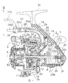
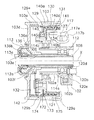
図1に示す本発明の参考例によるスピニングリールは、釣り竿の長手方向に沿う第1軸X回りに釣り糸を巻き取るリールであって、ハンドル1を備えたリール本体2と、リール本体2の前部に第1軸X回りに回転自在に支持されたロータ3と、ロータ3の前部に配置された釣り糸を巻き取るスプール4とを備えている。
[ Reference example ]
〔overall structure〕
A spinning reel according to a reference example of the present invention shown in FIG. 1 is a reel that winds a fishing line around a first axis X along the longitudinal direction of a fishing rod, and includes a reel body 2 having a handle 1 and a front of the reel body 2. The rotor 3 is rotatably supported around the first axis X, and the spool 4 is disposed on the front portion of the rotor 3 and winds a fishing line.

リール本体2は、例えば合成樹脂製である。リール本体2は、図1及び図3に示すように、釣り竿に装着される前後に長い装着部2cと、装着部2cと間隔を隔てて配置されたリールボディ2aと、装着部2cとリールボディ2aとを連結する脚部2bとを有している。リールボディ2aは、内部に機構装着空間を有し、脚部2bと一体形成され側部が開口する筐体部2fと、筐体部2fを塞ぐ蓋部材2d(図3)とを有している。リールボディ2aの前部には、取付フランジ付きの金属製の筒状の取付部材2eが装着されている。   The reel body 2 is made of, for example, a synthetic resin. As shown in FIGS. 1 and 3, the reel body 2 includes a mounting portion 2 c that is long before and after being mounted on a fishing rod, a reel body 2 a that is spaced from the mounting portion 2 c, and a mounting portion 2 c and a reel body. 2a to connect 2a. The reel body 2a has a mechanism mounting space inside, and includes a housing part 2f that is integrally formed with the leg part 2b and has an open side part, and a lid member 2d (FIG. 3) that closes the housing part 2f. Yes. A metal cylindrical mounting member 2e with a mounting flange is mounted on the front portion of the reel body 2a.

リールボディ2aの内部には、ロータ3を回転させるためのロータ駆動機構5と、ロータ3の糸繰り出し方向の回転(逆転)を制動するためのレバーブレーキ機構(ロータ制動装置の一例)6と、スプール軸8を介してスプール4を前後に往復移動させるオシレーティング機構20とが設けられている。   Inside the reel body 2a, there are a rotor drive mechanism 5 for rotating the rotor 3, a lever brake mechanism (an example of a rotor braking device) 6 for braking the rotation (reverse rotation) of the rotor 3 in the yarn feeding direction, An oscillating mechanism 20 that reciprocally moves the spool 4 back and forth via the spool shaft 8 is provided.

ロータ3は例えば合成樹脂又は金属製であり、リール本体2に回転自在に支持されている。ロータ3は、円筒部3aと、円筒部3aの側方に互いに対向して設けられた第1アーム部3b及び第2アーム部3cとを有している。また、図2に示すように、円筒部3aの前壁3d側の内周面には、ワンウェイクラッチ32(後述)を構成する鋸歯状の凹凸部42が形成されている。円筒部3aの前壁3dの中央部には貫通孔3eを有するボス部3fが形成されている。この貫通孔3eにスプール軸8及びピニオンギア12(後述)が貫通している。図1に示すように、第1アーム部3bの先端と第2アーム部3cの先端部とには、揺動自在にベールアーム9が設けられている。このベールアーム9により釣り糸がスプール4に案内される。   The rotor 3 is made of, for example, synthetic resin or metal, and is rotatably supported by the reel body 2. The rotor 3 includes a cylindrical portion 3a and a first arm portion 3b and a second arm portion 3c provided on the side of the cylindrical portion 3a so as to face each other. In addition, as shown in FIG. 2, a serrated uneven portion 42 constituting a one-way clutch 32 (described later) is formed on the inner peripheral surface of the cylindrical portion 3a on the front wall 3d side. A boss 3f having a through hole 3e is formed at the center of the front wall 3d of the cylindrical portion 3a. The spool shaft 8 and the pinion gear 12 (described later) pass through the through hole 3e. As shown in FIG. 1, bail arms 9 are swingably provided at the tip of the first arm portion 3b and the tip of the second arm portion 3c. The fishing line is guided to the spool 4 by the bail arm 9.

スプール4は、例えば合成樹脂と金属とを複合したハイブリッド型のものである。スプール4は、ロータ3の第1アーム部3bと第2アーム部3cとの間に配置されており、スプール軸8の先端にワンタッチ着脱機構65を介して着脱自在かつ回転不能に装着されている。スプール4は、糸巻胴部7aを有するスプール本体7と、糸巻胴部7aの前端部に取り付けられた大径の前フランジ部51と、前フランジ部51をスプール本体7に固定するための前フランジ固定部材52とを有している。スプール本体7は、外周に釣り糸が巻かれる筒状の糸巻胴部7aと、糸巻胴部7aの後端部に一体成形された大径筒状のスカート部7bと、糸巻胴部7aの内周側に取り付けられた内筒部材7cとを有している。   The spool 4 is, for example, a hybrid type in which a synthetic resin and a metal are combined. The spool 4 is disposed between the first arm portion 3b and the second arm portion 3c of the rotor 3, and is detachably and non-rotatably attached to the tip of the spool shaft 8 via a one-touch attachment / detachment mechanism 65. . The spool 4 includes a spool main body 7 having a bobbin trunk 7a, a large-diameter front flange 51 attached to the front end of the bobbin trunk 7a, and a front flange for fixing the front flange 51 to the spool main body 7. And a fixing member 52. The spool body 7 includes a cylindrical bobbin trunk 7a around which the fishing line is wound, a large-diameter cylindrical skirt 7b integrally formed at the rear end of the bobbin trunk 7a, and an inner periphery of the bobbin trunk 7a. And an inner cylinder member 7c attached to the side.

糸巻胴部7a及びスカート部7bは、アルミニウム合金、ステンレス合金、チタン合金、マグネシウム合金などの金属薄板をプレス加工により一体成形して得られた大小2段の筒状の部材である。   The bobbin trunk portion 7a and the skirt portion 7b are large and small two-stage cylindrical members obtained by integrally forming a thin metal plate such as an aluminum alloy, a stainless alloy, a titanium alloy, or a magnesium alloy by pressing.

ロータ駆動機構5は、図1に示すように、ハンドル1が回転不能に固定されたハンドル軸10とともに回転するマスターギア11と、このマスターギア11に噛み合うピニオンギア12とを有している。ハンドル軸10は、リール本体2に回転自在に支持されている。図2に示すように、ピニオンギア12は筒状に形成されており、その前部12aはロータ3の貫通孔3eを貫通してスプール4側に延びている。この前部12aで、ロータ3はナット13によりピニオンギア12に回転不能に固定されている。ピニオンギア12は、前部と中間部とで軸受14a,14bによりリール本体2に回転自在に支持されている。なお、前部の軸受14aは、リール本体2を構成する取付部材2eの内周面に装着されている。ナット13は、リテーナ36により緩み止めされている。リテーナ36は前壁3dに形成されたねじ孔にねじ止め固定されたビスにより固定されている。   As shown in FIG. 1, the rotor drive mechanism 5 includes a master gear 11 that rotates together with a handle shaft 10 on which the handle 1 is fixed so as not to rotate, and a pinion gear 12 that meshes with the master gear 11. The handle shaft 10 is rotatably supported by the reel body 2. As shown in FIG. 2, the pinion gear 12 is formed in a cylindrical shape, and the front portion 12 a extends through the through hole 3 e of the rotor 3 to the spool 4 side. At the front portion 12a, the rotor 3 is fixed to the pinion gear 12 by a nut 13 so as not to rotate. The pinion gear 12 is rotatably supported on the reel body 2 by bearings 14a and 14b at the front portion and the intermediate portion. The front bearing 14a is mounted on the inner peripheral surface of the mounting member 2e constituting the reel body 2. The nut 13 is prevented from loosening by a retainer 36. The retainer 36 is fixed to a screw hole formed in the front wall 3d by a screw fixed by screwing.

オシレーティング機構20は、図1に示すように、減速ギア式のものであり、ハンドル軸10に一体形成された駆動ギア20aと、リールボディ2aに回転自在に装着されたカム付き従動ギア20bと、カム付き従動ギア20bの回転により前後移動するスライダ20cとを有している。スライダ20cにスプール軸8の後端部が回転不能かつ軸方向移動不能に取り付けられている。   As shown in FIG. 1, the oscillating mechanism 20 is of a reduction gear type, and includes a drive gear 20a integrally formed with the handle shaft 10, and a cam-equipped driven gear 20b rotatably mounted on the reel body 2a. The slider 20c moves back and forth by the rotation of the cam-equipped driven gear 20b. The rear end portion of the spool shaft 8 is attached to the slider 20c so as not to rotate but to move in the axial direction.

〔レバーブレーキ機構の構成〕
レバーブレーキ機構6は、図1〜図3に示すように、制動部16と、制動部16の制動力を調整操作するための制動レバー17と、制動部16を所定制動状態に操作するための補助レバー(切換操作部の一例)18と、制動レバー17を装着部2cから離反する方向に付勢するコイルばね19と、補助レバー18により所定制動状態と制動解除状態とに切換可能な所定制動部21(図3)とを有している。
[Configuration of lever brake mechanism]
As shown in FIGS. 1 to 3, the lever brake mechanism 6 includes a braking unit 16, a braking lever 17 for adjusting the braking force of the braking unit 16, and a brake unit 16 for operating the braking unit 16 to a predetermined braking state. Auxiliary lever (an example of a switching operation unit) 18, a coil spring 19 that urges the braking lever 17 in a direction away from the mounting portion 2c, and a predetermined braking that can be switched between a predetermined braking state and a braking release state by the auxiliary lever 18 Part 21 (FIG. 3).

〔制動部の構成〕
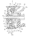
制動部16は、図2に示すように、制動レバー17の先端が圧接されて制動される制動部本体(回転部材の一例)31と、制動部本体31をロータ3の糸繰り出し方向の回転にのみ連動して回転させる爪式のワンウェイクラッチ32とを有している。
[Configuration of braking section]
As shown in FIG. 2, the braking portion 16 includes a braking portion main body (an example of a rotating member) 31 that is braked by pressing the tip of the braking lever 17, and the braking portion main body 31 is rotated in the direction in which the rotor 3 is fed out. And a claw-type one-way clutch 32 that rotates only in conjunction with each other.

制動部本体31は、ロータ3の内周側にロータ3と同心に配置された筒状部材40と、筒状部材40の内周面に固定された制動円筒41とを有している。   The brake section main body 31 includes a cylindrical member 40 disposed concentrically with the rotor 3 on the inner peripheral side of the rotor 3, and a brake cylinder 41 fixed to the inner peripheral surface of the cylindrical member 40.

筒状部材40は、図2に示すように、円筒部3aの内周側に同芯に配置される外筒部40aと、外筒部40aの内周側に配置された内筒部40bと、外筒部40aと内筒部40bとを連結する円板部40cとを有する二重筒状部材である。外筒部40aのリール本体2に近い後端部の外周面には、所定制動部21を構成する摩擦部材(後述)が装着される環状溝40dが形成されている。内筒部40bは、取付部材2eの外周面に装着された軸受14cにより取付部材2eに回転自在に装着されている。   As shown in FIG. 2, the cylindrical member 40 includes an outer cylindrical portion 40a disposed concentrically on the inner peripheral side of the cylindrical portion 3a, and an inner cylindrical portion 40b disposed on the inner peripheral side of the outer cylindrical portion 40a. This is a double cylindrical member having a disc part 40c that connects the outer cylinder part 40a and the inner cylinder part 40b. An annular groove 40d in which a friction member (described later) constituting the predetermined braking portion 21 is mounted is formed on the outer peripheral surface of the rear end portion near the reel body 2 of the outer cylinder portion 40a. The inner cylinder portion 40b is rotatably attached to the attachment member 2e by a bearing 14c attached to the outer peripheral surface of the attachment member 2e.

制動円筒41は、外筒部40aの内周面から円板部40cにかけて装着された中心孔を有する金属製の有底筒状部材であり、円板部40cにねじ止め固定されている。この制動円筒41の内周面に制動レバー17の先端が当接して筒状部材40を制動する。   The brake cylinder 41 is a metal bottomed cylindrical member having a center hole mounted from the inner peripheral surface of the outer cylinder part 40a to the disk part 40c, and is fixed to the disk part 40c by screws. The tip of the brake lever 17 comes into contact with the inner peripheral surface of the brake cylinder 41 to brake the tubular member 40.

ワンウェイクラッチ32は爪式のものであり、ロータ3の円筒部3aの内周側面に形成された凹凸部42と、円板部40cに揺動自在に装着され先端が凹凸部42に接触可能なクラッチ爪43と、クラッチ爪43を先端が凹凸部42に接触する方向に付勢する捩じりばね44とを有している。ワンウェイクラッチ32は、前述したようにロータ3の糸繰り出し方向の回転にのみ連動して筒状部材40が回転させる。   The one-way clutch 32 is of a claw type, and is provided with a concavo-convex portion 42 formed on the inner peripheral side surface of the cylindrical portion 3a of the rotor 3 and a disc portion 40c so as to be swingable, and the tip can contact the concavo-convex portion 42. A clutch pawl 43 and a torsion spring 44 that urges the clutch pawl 43 in a direction in which the tip contacts the concavo-convex portion 42 are provided. As described above, the one-way clutch 32 is rotated by the tubular member 40 only in conjunction with the rotation of the rotor 3 in the yarn feeding direction.

〔制動レバーの構成〕
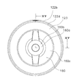
図1に示すように、制動レバー17は、第1軸Xと食い違う第2軸Y方向にリール本体2のリールボディ2aに装着された支持軸33によりリール本体2に第2軸Y回りに揺動自在に支持されている。支持軸33は、図3に示すように、鍔付きの軸部材であり、蓋部材2dを筐体部2fに装着するためのねじ部材である。支持軸33は、蓋部材2d側から挿入されたねじ33aに螺合してリール本体2に固定されている。また、前述したように、制動レバー17は、コイルばね19により装着部2cと離反する方向に付勢されている。制動レバー17は、図7に示す制動解除位置と、制動解除位置より装着部2cに接近した図5に示す制動位置との間で揺動自在にリール本体2に取り付けられている。
[Configuration of braking lever]
As shown in FIG. 1, the brake lever 17 swings around the second axis Y around the reel body 2 by the support shaft 33 mounted on the reel body 2 a of the reel body 2 in the second axis Y direction, which is different from the first axis X. It is supported freely. As shown in FIG. 3, the support shaft 33 is a shaft member with a hook, and is a screw member for mounting the lid member 2d to the housing portion 2f. The support shaft 33 is fixed to the reel body 2 by screwing into a screw 33a inserted from the lid member 2d side. Further, as described above, the brake lever 17 is urged by the coil spring 19 in a direction away from the mounting portion 2c. The brake lever 17 is attached to the reel body 2 so as to be swingable between a brake release position shown in FIG. 7 and a brake position shown in FIG. 5 which is closer to the mounting portion 2c than the brake release position.

制動レバー17は、支持軸33による支持部分から湾曲して前方に延びる制動操作部17aと、支持部分から湾曲して斜め前下方に延びる制動作用部17bと、制動作用部17bに着脱自在に装着された制動シュー34とを有している。このように制動レバー17をリールボディ2aに揺動自在に装着したので、制動レバー17の先端の制動操作部17aから支持軸33の揺動支点が離れるとともに、制動作用部17bと揺動支点とが接近する。このため、軽い操作力で大きな制動力を得ることができる。   The brake lever 17 is detachably attached to the brake operation portion 17a that is curved from the support portion by the support shaft 33 and extends forward, the brake operation portion 17b that is curved from the support portion and extends obliquely forward and downward, and the brake operation portion 17b. Braking brake 34. Since the brake lever 17 is swingably mounted on the reel body 2a as described above, the swing fulcrum of the support shaft 33 is separated from the brake operation portion 17a at the tip of the brake lever 17, and the braking action portion 17b and the swing fulcrum Approaches. For this reason, a large braking force can be obtained with a light operating force.

制動操作部17aは、支持部分から装着部2cに沿ってベールアーム9の外方付近まで前方に延びた後、径方向外方に向けて延び、さらに先端が前方に向けて湾曲した形状である。この湾曲部分から前方が釣り竿を握る手の人差し指で操作可能な第1操作部17cとなっている。第1操作部17cは、制動レバー17の揺動により図1に示す制動解除位置から装着部2cに接近する方向に移動可能である。制動操作部17aは、図3及び図4に示すように、脚部2bから前方部分にかけて、径方向外方に延びる部分まで幅が大きくなっており、その幅広部分17hには、装着部2cに向けて略矩形の開口17eが形成されている。この開口17eから後述する補助レバー18の操作部材26が装着部2cに向かって露出している。また、幅広部分17hから前方に向けて切欠き17gが形成されている。この切欠き17gを貫通して前方に向かって操作部材26が突出している。この切欠き17gの開口部分には、制動レバー17と補助レバー18との隙間から釣り糸が侵入して糸カミが生じるのを防止するために、板状の閉塞板35がビス止めされている。   The braking operation portion 17a has a shape that extends forward from the support portion to the vicinity of the outside of the bail arm 9 along the mounting portion 2c, then extends radially outward, and further has a tip curved toward the front. . The first operation portion 17c that can be operated with the index finger of the hand holding the fishing rod forward from the curved portion. The first operation portion 17c is movable in the direction of approaching the mounting portion 2c from the brake release position shown in FIG. As shown in FIGS. 3 and 4, the braking operation portion 17a has a width that extends from the leg portion 2b to the front portion to a portion extending radially outward, and the wide portion 17h includes the mounting portion 2c. A substantially rectangular opening 17e is formed. An operation member 26 of the auxiliary lever 18 described later is exposed from the opening 17e toward the mounting portion 2c. Further, a notch 17g is formed from the wide portion 17h toward the front. An operating member 26 protrudes forward through the notch 17g. A plate-shaped closing plate 35 is screwed into the opening of the notch 17g in order to prevent fishing line from entering through the gap between the brake lever 17 and the auxiliary lever 18 and causing line scum.

制動作用部17bの先端は、制動円筒41の内周側に対向して配置され、図2に示すように、その先端に制動円筒41の内周面に接触可能な制動シュー34が着脱自在に取り付けられている。制動シュー34は、たとえばポリアミド系合成樹脂やポリアセタールなどの弾性を有する合成樹脂製であり、制動レバー17の揺動により制動円筒41を径方向外方に押圧する。   The distal end of the braking action portion 17b is arranged to face the inner peripheral side of the braking cylinder 41, and a braking shoe 34 that can contact the inner peripheral surface of the braking cylinder 41 is detachable at the distal end as shown in FIG. It is attached. The brake shoe 34 is made of, for example, a synthetic resin having elasticity, such as a polyamide-based synthetic resin or polyacetal, and presses the brake cylinder 41 radially outward by swinging of the brake lever 17.

制動レバー17は、何も操作されないとコイルばね19により付勢されて、図1に示すように、制動解除位置に配置されて制動シュー34が制動円筒41から離反している。   The brake lever 17 is biased by the coil spring 19 when nothing is operated, and is disposed at the brake release position so that the brake shoe 34 is separated from the brake cylinder 41 as shown in FIG.

コイルばね19は、制動レバー17の制動操作部17aとリール本体2の脚部2bとの間に圧縮状態で配置されている。コイルばね19は、制動レバー17を制動解除側に向けて図1反時計回りに付勢している。これにより、制動レバー17から手を離すと、ロータ3は制動解除状態になる。   The coil spring 19 is disposed in a compressed state between the braking operation portion 17 a of the braking lever 17 and the leg portion 2 b of the reel body 2. The coil spring 19 urges the brake lever 17 counterclockwise in FIG. 1 toward the brake release side. As a result, when the hand is released from the brake lever 17, the rotor 3 enters the brake release state.

〔補助レバーの構成〕
補助レバー18は、所定制動部21を図7に示す制動解除状態と図6に示す所定制動状態とに切り換える操作を行うためのものである。補助レバー18は、図7に示すように、第2操作部26a(後述)が装着部2cに接近した第2位置に配置される制動解除位置と、図6に示すように、第2操作部26aが装着部2cから離反した第3位置に配置される所定制動位置との間で揺動する。補助レバー18は、図1、図3及び図4に示すように、支持軸33に第2軸Y回りに揺動自在にリール本体2に支持された板状の第1レバー部材25と、第1レバー部材25に装着された操作部材26とを有している。
[Configuration of auxiliary lever]
The auxiliary lever 18 is for performing an operation of switching the predetermined braking portion 21 between a braking release state shown in FIG. 7 and a predetermined braking state shown in FIG. As shown in FIG. 7, the auxiliary lever 18 includes a brake release position where a second operation portion 26a (described later) is disposed at a second position close to the mounting portion 2c, and a second operation portion as shown in FIG. 26a swings between a predetermined braking position arranged at a third position separated from the mounting portion 2c. As shown in FIGS. 1, 3 and 4, the auxiliary lever 18 includes a plate-like first lever member 25 supported on the reel body 2 so as to be swingable about the second axis Y on the support shaft 33, and a first lever member 25. 1 has an operation member 26 mounted on the lever member 25.

第1レバー部材25は、制動レバー17の図5手前側側面に並べて配置されている。第1レバー部材25は、支持部分から制動レバー17に沿って上前方及び前下方に延びており、前上方に延びた先端には、たとえば2本のねじ25aにより操作部材26が固定されている。第1レバー部材25の先端は制動レバー17の制動操作部17aの幅広部分17hの開口17e内に位置している。また、支持部分より斜め前下方に延びた第1レバー部材25の基端は、制動部16の径方向内方かつ後方に配置されている。第1レバー部材25の基端には、所定制動部21の第2レバー部材27の先端が係止される矩形の係止切欠き25c(図2)が形成されている。係止切欠き25cは、第2レバー部材27の先端部の横断面積より大きい面積の基端側に開口する矩形の切欠きである。   The first lever member 25 is arranged side by side on the front side surface of the brake lever 17 in FIG. The first lever member 25 extends upward and forward and downward and forward along the brake lever 17 from the support portion, and an operation member 26 is fixed to a front end of the front and upward by, for example, two screws 25a. . The tip of the first lever member 25 is located in the opening 17e of the wide portion 17h of the braking operation portion 17a of the braking lever 17. Further, the base end of the first lever member 25 that extends obliquely forward and downward from the support portion is disposed radially inward and rearward of the braking portion 16. At the base end of the first lever member 25, a rectangular locking notch 25 c (FIG. 2) in which the tip of the second lever member 27 of the predetermined braking portion 21 is locked is formed. The locking notch 25 c is a rectangular notch that opens to the base end side having an area larger than the transverse area of the distal end portion of the second lever member 27.

操作部材26は、先端に第2操作部26aを有している。第2操作部26aは、装着部2cから離反する側に第1操作部17cと対向して配置されている。このため、第2操作部26aは、釣り竿を握る手の人差し指で押し込み操作可能である。第1操作部17cと第2操作部26aは、同じ指による引き込み操作と押し込み操作とが可能である。第2操作部26aは、補助レバー18の揺動により図1及び図7に示す第2位置と図6に示す第3位置とに配置される。   The operation member 26 has a second operation portion 26a at the tip. The second operation portion 26a is disposed on the side away from the mounting portion 2c so as to face the first operation portion 17c. For this reason, the 2nd operation part 26a can be pushed in with the index finger of the hand which grasps a fishing rod. The first operation unit 17c and the second operation unit 26a can perform a pull-in operation and a push-in operation with the same finger. The second operating portion 26a is disposed at the second position shown in FIGS. 1 and 7 and the third position shown in FIG.

操作部材26は、開口17eの下部から切欠き17g及び閉塞板35で囲まれた空間を貫通して前方に延びており、延びた先端に第2操作部26aが形成されている。このように第2操作部26aが切欠き17g及び閉塞板35で囲まれた空間を貫通して前方に延びているので、第2操作部26aの周囲、特にベールアーム9に近接する部分が空間により囲まれる。このため、釣り糸が糸ふけによりこの部分に接触しても操作部材26と制動レバー17との隙間への釣り糸の噛み込み(糸カミ)が生じにくくなる。また、切欠き17gを閉塞板35で塞いでいるので、操作部材26を取り付けた後に閉塞板35を取り付けて空間を塞ぐことができる。このため、操作部材26を取り付けしやすくなる。   The operating member 26 extends forward through the space surrounded by the notch 17g and the blocking plate 35 from the lower portion of the opening 17e, and a second operating portion 26a is formed at the extended tip. As described above, since the second operation portion 26a extends forward through the space surrounded by the notch 17g and the blocking plate 35, the periphery of the second operation portion 26a, in particular, a portion close to the bail arm 9 is a space. Surrounded by For this reason, even if the fishing line comes into contact with this portion due to the dandruff, the fishing line is less likely to be caught in the gap between the operation member 26 and the brake lever 17 (line scum). Further, since the notch 17g is closed by the closing plate 35, the space can be closed by attaching the closing plate 35 after the operation member 26 is attached. For this reason, it becomes easy to attach the operation member 26.

また、補助レバー18が所定制動位置に配置されると、図6に示すように、第2操作部26aの下面は、制動操作部17aの閉塞板35にほぼ接触する。これにより、補助レバー18は、所定制動位置にあるとき、制動レバー17の装着部2cに接近する方向の揺動に連動して制動解除位置に揺動する。   Further, when the auxiliary lever 18 is disposed at the predetermined braking position, as shown in FIG. 6, the lower surface of the second operation portion 26a substantially comes into contact with the closing plate 35 of the braking operation portion 17a. As a result, when the auxiliary lever 18 is in the predetermined braking position, the auxiliary lever 18 swings to the braking release position in conjunction with the swing of the braking lever 17 in the direction approaching the mounting portion 2c.

〔所定制動部の構成〕
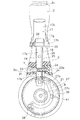
所定制動部21は、図3に示すように、第1レバー部材25と連動して揺動する第2レバー部材(切換動作部の一例)27と、第2レバー部材27を制動解除位置と所定制動位置とで保持するトグルばね28と、筒状部材40に相対回転可能に装着され筒状部材40に摩擦係合する摩擦部材29とを有している。第2レバー部材27は、図3及び図8に示すように、リール本体2の前部にスプール軸8と平行に配置された揺動軸27aに揺動自在に装着されている。第2レバー部材27の基端から揺動中心までの距離は、先端から揺動中心までの距離より2倍以上長い。第2レバー部材27の先端は、係止切欠き25cに係止されており、第2レバー部材27は、第1レバー部材25と連動して制動解除位置(図8(a))と所定制動位置(図8(b))との間で揺動する。
[Configuration of the specified braking part]
As shown in FIG. 3, the predetermined braking unit 21 includes a second lever member 27 (an example of a switching operation unit) that swings in conjunction with the first lever member 25, and a second lever member 27 that has a predetermined braking release position. A toggle spring 28 is held at the braking position, and a friction member 29 is attached to the tubular member 40 so as to be relatively rotatable and frictionally engages with the tubular member 40. As shown in FIGS. 3 and 8, the second lever member 27 is swingably mounted on a swing shaft 27 a disposed in parallel with the spool shaft 8 at the front portion of the reel body 2. The distance from the base end of the second lever member 27 to the swing center is at least twice as long as the distance from the tip to the swing center. The tip of the second lever member 27 is locked to the locking notch 25c, and the second lever member 27 is interlocked with the first lever member 25 and the brake release position (FIG. 8A) and the predetermined braking. It swings between the positions (FIG. 8 (b)).

ここで、制動解除位置あるとき第2レバー部材27の基端はトグルばね28により付勢されて係止切欠き25cの上面に接触し、所定制動位置にあるとき下面に接触する。第2レバー部材27の途中には、先端が筒状部材40に装着された摩擦部材29に係合する係合部材39が設けられている。係合部材39は、第2レバー部材27の途中に装着された装着部27cに一体形成されており、装着部27cから筒状部材40の略径方向に延びている。第2レバー部材27は、係合部材39の装着部分からさらに湾曲して延びており、延びた基端にトグルばね28が装着されている。   Here, the base end of the second lever member 27 is urged by the toggle spring 28 when in the braking release position and contacts the upper surface of the locking notch 25c, and contacts the lower surface when in the predetermined braking position. In the middle of the second lever member 27, an engagement member 39 is provided that engages a friction member 29 having a tip attached to the cylindrical member 40. The engaging member 39 is integrally formed with the mounting portion 27 c mounted in the middle of the second lever member 27, and extends from the mounting portion 27 c in the substantially radial direction of the tubular member 40. The second lever member 27 extends further in a curved manner from the mounting portion of the engaging member 39, and the toggle spring 28 is mounted on the extended base end.

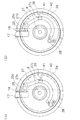
摩擦部材29は、図9から図11に示すように、筒状部材40の外筒部40aの外周面に形成された環状溝40dに装着されている。摩擦部材29は、リングを半分に切断した形状の略半円形の2つの分割部材29a,29bで構成されている。各分割部材29a,29bは、たとえば金属薄板をプレス成形して形成された部材である。各分割部材29a,29bは、筒状部材40に対して相対回転可能に摩擦係合する断面がC字状の摩擦部37と、制動位置に移動した係合部材39の先端が係合する複数の係合部38とをそれぞれ有している。各分割部材29a,29bは、摩擦部37に形成された装着溝37aに装着されたばね部材30により、環状溝40dに圧接されている。ばね部材30は、たとえば、金属製の環状に湾曲された弾性線材で構成されている。   As shown in FIGS. 9 to 11, the friction member 29 is mounted in an annular groove 40 d formed on the outer peripheral surface of the outer cylindrical portion 40 a of the cylindrical member 40. The friction member 29 includes two substantially semicircular divided members 29a and 29b each having a shape obtained by cutting a ring in half. Each divided member 29a, 29b is a member formed by press-molding a metal thin plate, for example. Each of the split members 29a and 29b has a plurality of C-shaped friction portions 37 that are frictionally engaged with the cylindrical member 40 so as to be relatively rotatable, and a plurality of engagement members 39 that are moved to the braking position. Each of the engaging portions 38. Each of the divided members 29a and 29b is pressed against the annular groove 40d by a spring member 30 mounted in a mounting groove 37a formed in the friction portion 37. The spring member 30 is made of, for example, an elastic wire made of a metal and curved in an annular shape.

係合部38は、摩擦部37から後方に延びる円筒状の部分であり、その一端部に周方向に間隔を隔てて形成された多数の係合凹部38aを有している。この係合凹部38aに係合部材39の先端が係合可能である。係合凹部38aは、たとえば、各分割部材29a,29bにそれぞれ20以上形成されている。このような多数の係合凹部38aを形成することにより、第2レバー部材27を所定制動位置に揺動させたとき、係合部材39が係合凹部38aに係合しやすくなる。   The engaging portion 38 is a cylindrical portion extending rearward from the friction portion 37, and has a large number of engaging recesses 38 a formed at one end thereof at intervals in the circumferential direction. The front end of the engagement member 39 can be engaged with the engagement recess 38a. For example, 20 or more engaging recesses 38a are formed in each of the divided members 29a and 29b. By forming such a large number of engaging recesses 38a, the engaging member 39 can be easily engaged with the engaging recesses 38a when the second lever member 27 is swung to a predetermined braking position.

このような構成の摩擦部材29では、第2レバー部材27が所定制動位置に配置され係合部材39が係合部38の係合凹部38aに係合したとき、摩擦部37が筒状部材40に対して摩擦摺動する。   In the friction member 29 having such a configuration, when the second lever member 27 is disposed at a predetermined braking position and the engagement member 39 is engaged with the engagement recess 38 a of the engagement portion 38, the friction portion 37 is the tubular member 40. Friction sliding against.

ここでは、第2位置にある第2操作部26aを押し込み操作して第3位置に配置し、第1レバー部材25を、図7に示す制動解除位置から図6に示す第1所定制動位置側に揺動させると、それに連動して第2レバー部材27も制動解除位置から所定制動位置に揺動する。この結果、係合部材39が摩擦部材29の係合部38に係合し、ロータ3の糸繰り出し方向の回転を所定制動状態で制動する。   Here, the second operating portion 26a at the second position is pushed in and arranged at the third position, and the first lever member 25 is moved from the braking release position shown in FIG. 7 to the first predetermined braking position side shown in FIG. When the second lever member 27 is swung to the predetermined brake position, the second lever member 27 is also swung from the brake release position to the predetermined brake position. As a result, the engaging member 39 engages with the engaging portion 38 of the friction member 29 and brakes the rotation of the rotor 3 in the yarn unwinding direction in a predetermined braking state.

トグルばね28は、図3及び図8に示すように、第2レバー部材27を付勢して第2操作部26aを第2位置と第3位置とに振り分けて付勢し、その姿勢を保持することができる。トグルばね28は、第2レバー部材27の基端に装着された捩じりコイルばねである。トグルばね28は、一端が第2レバー部材27の基端に係止され、他端がリールボディ2aの前端面に係止されている。トグルばね28は、図8(a)に示すように、第2レバー部材27が制動解除位置に配置されると、第2レバー部材27を図8(a)の時計回りに付勢し、所定制動位置に配置されると図8(b)の反時計回りに付勢する。これにより、第2レバー部材27が制動解除位置と所定制動位置とで保持され、さらに第1レバー部材25が制動解除位置と所定制動位置とに保持される。   As shown in FIGS. 3 and 8, the toggle spring 28 biases the second lever member 27 and urges the second operation portion 26a to be distributed between the second position and the third position, and maintains its posture. can do. The toggle spring 28 is a torsion coil spring attached to the base end of the second lever member 27. One end of the toggle spring 28 is locked to the base end of the second lever member 27, and the other end is locked to the front end surface of the reel body 2a. As shown in FIG. 8A, the toggle spring 28 urges the second lever member 27 in the clockwise direction of FIG. 8A when the second lever member 27 is disposed at the braking release position. When placed in the braking position, it is biased counterclockwise in FIG. As a result, the second lever member 27 is held at the brake release position and the predetermined brake position, and the first lever member 25 is held at the brake release position and the predetermined brake position.

ここでは、第2レバー部材27の基端から揺動中心までの距離が先端から揺動中心までの距離より2倍以上長いので、第1レバー部材25が揺動すると、その揺動が第2レバー部材27の基端側で2倍以上の揺動距離となって現れ、トグルばね28が容易に反転可能になる。   Here, since the distance from the base end of the second lever member 27 to the swing center is more than twice as long as the distance from the tip to the swing center, when the first lever member 25 swings, the swing is second. The lever member 27 appears at the base end side of the lever member 27 with a swing distance more than twice, and the toggle spring 28 can be easily reversed.

〔リールの動作及び操作〕
キャスティング時にはベールアーム9を糸開放姿勢側に倒し、キャスティングすることにより、スプール4の外周から釣り糸が繰り出される。糸巻取時には、ハンドル1を糸巻き取り方向に回転させると、ベールアーム9が図示しない戻し機構により糸巻き取り姿勢に戻る。ハンドル1の回転力は、ハンドル軸10、マスターギア11を介してピニオンギア12に伝達される。ピニオンギア12に伝達された回転力は、ピニオンギアの前部12aを介してロータ3に伝達される。このときロータ3は糸巻き取り方向に回転するので、ワンウェイクラッチ32の作用によりこの回転力は筒状部材40には伝達されない。ピニオンギア12が回転すると、スプール軸8が前後方向に往復移動する。
[Reel operation and operation]
At the time of casting, the fishing line is fed out from the outer periphery of the spool 4 by tilting the bail arm 9 toward the line releasing posture and casting. At the time of winding the yarn, if the handle 1 is rotated in the yarn winding direction, the bail arm 9 returns to the yarn winding posture by a return mechanism (not shown). The rotational force of the handle 1 is transmitted to the pinion gear 12 via the handle shaft 10 and the master gear 11. The rotational force transmitted to the pinion gear 12 is transmitted to the rotor 3 via the front portion 12a of the pinion gear. At this time, since the rotor 3 rotates in the yarn winding direction, the rotational force is not transmitted to the tubular member 40 by the action of the one-way clutch 32. When the pinion gear 12 rotates, the spool shaft 8 reciprocates in the front-rear direction.

制動レバー17を何も操作しなければ、制動レバー17はコイルばね19により押圧され制動解除位置側に配置される。このとき、補助レバー18の第2操作部26aが第2位置に配置されていると、図5、図8(a)に示すように、制動シュー34が制動円筒41から離反するとともに、係合部材39が係合部38から離反し、ロータ3は制動解除状態になる。   If nothing is operated on the brake lever 17, the brake lever 17 is pressed by the coil spring 19 and arranged on the brake release position side. At this time, if the second operation portion 26a of the auxiliary lever 18 is disposed at the second position, the brake shoe 34 is separated from the brake cylinder 41 and engaged as shown in FIGS. The member 39 is separated from the engaging portion 38, and the rotor 3 is in a brake release state.

ロータ3を逆転させて魚とやりとりする時には、制動レバー17の第1操作部17cを例えば人差し指により装着部2c側に引き込み操作して制動力を調整する。   When exchanging with the fish by reversing the rotor 3, the braking force is adjusted by pulling the first operating portion 17c of the braking lever 17 toward the mounting portion 2c with, for example, an index finger.

釣り糸が魚により引かれてロータ3が糸繰り出し方向に逆転すると、その回転力がワンウェイクラッチ32を介して筒状部材40に伝達され、さらに制動円筒41に伝達される。この結果、制動円筒41がロータ3と一体で回転する。制動レバー17の第1操作部17cを装着部2cに接近する方向に引き込み操作すると、たとえ第2レバー部材27が所定制動位置にあっても、図6に示すように閉塞板35が操作部材26の第2操作部26aを装着部2cに接近する方向に押圧し、補助レバー18が制動レバー17に連動して所定制動位置から制動解除位置側に揺動し、第2レバー部材27が制動解除位置側に揺動する。この結果、所定制動部21による所定制動状態が一旦解除される。このとき、トグルばね28が第2レバー部材27の揺動により反転し、第2レバー部材27が制動解除位置側に付勢され、第1レバー部材25が制動解除位置側で保持される(図8(a))。   When the fishing line is pulled by the fish and the rotor 3 reverses in the line-feeding direction, the rotational force is transmitted to the tubular member 40 via the one-way clutch 32 and further to the braking cylinder 41. As a result, the brake cylinder 41 rotates integrally with the rotor 3. When the first operating portion 17c of the brake lever 17 is pulled in the direction approaching the mounting portion 2c, even if the second lever member 27 is at the predetermined braking position, the closing plate 35 is operated as shown in FIG. The second operating portion 26a is pressed in the direction approaching the mounting portion 2c, the auxiliary lever 18 swings from the predetermined braking position to the braking releasing position side in conjunction with the braking lever 17, and the second lever member 27 releases the braking. Swings to the position side. As a result, the predetermined braking state by the predetermined braking unit 21 is once released. At this time, the toggle spring 28 is reversed by the swing of the second lever member 27, the second lever member 27 is urged to the brake release position side, and the first lever member 25 is held on the brake release position side (FIG. 8 (a)).

この状態でさらに制動レバー17を装着部2cに接近する方向に操作すると、制動レバー17の制動シュー34が制動円筒41内周面を径方向外方に強く押圧する。この制動力は制動レバー17に加える力を加減することにより調整でき、ロータ3の逆転量を任意に調整できる。この結果、制動レバー17の操作力に応じた制動力がロータ3に付与される。このように、所定制動状態の解除を忘れても、制動レバー17を引き込み操作するだけで、所定制動状態を解除できる。   In this state, when the brake lever 17 is further operated in a direction approaching the mounting portion 2c, the brake shoe 34 of the brake lever 17 strongly presses the inner peripheral surface of the brake cylinder 41 radially outward. This braking force can be adjusted by adjusting the force applied to the braking lever 17, and the amount of reverse rotation of the rotor 3 can be adjusted arbitrarily. As a result, a braking force corresponding to the operating force of the braking lever 17 is applied to the rotor 3. As described above, even if the user forgets to release the predetermined braking state, the predetermined braking state can be canceled by merely pulling the brake lever 17.

釣り場を移動する時やリールを収納する時には、第1操作部17cから手を離した状態で、補助レバー18の第2操作部26aを装着部2cから離反する方向に押し込み操作する。すると、図6及び図8(b)に示すように、補助レバー18が制動解除位置から所定制動位置に揺動し、第2レバー部材27が制動解除位置から所定制動位置に揺動し、トグルばね28によりその位置で保持される。この所定制動位置では、第2操作部26aの下面が閉塞板35にほぼ接触する。この結果、係合部材39が摩擦部材29の係合凹部38aに係合して摩擦部材29の回転が阻止され、ロータ3の逆転が阻止される。   When the fishing ground is moved or the reel is stored, the second operation portion 26a of the auxiliary lever 18 is pushed in a direction away from the mounting portion 2c while the hand is released from the first operation portion 17c. Then, as shown in FIGS. 6 and 8B, the auxiliary lever 18 swings from the brake release position to the predetermined brake position, and the second lever member 27 swings from the brake release position to the predetermined brake position. It is held in that position by a spring 28. At the predetermined braking position, the lower surface of the second operation portion 26a is substantially in contact with the closing plate 35. As a result, the engagement member 39 engages with the engagement recess 38a of the friction member 29, and the rotation of the friction member 29 is prevented, and the reverse rotation of the rotor 3 is prevented.

このときの制動力は、摩擦部材29の摩擦部材29の環状溝40dへの圧接度合い、この参考例では、ばね部材30の付勢力によって定められる。このため、移動途中にハンドル1に何かが当たってもハンドル1が回らない程度に強い所定制動力を得やすくなり、釣り場の移動途中に糸ふけが生じない程度に強く所定制動力を設定できる。また、摩擦部材29と筒状部材40との相対回転により制動するので、制動力が変動しにくくなり安定する。 The braking force at this time is determined by the degree of press contact of the friction member 29 to the annular groove 40d of the friction member 29, in this reference example , the urging force of the spring member 30. For this reason, it becomes easy to obtain a predetermined braking force that is strong enough that the handle 1 does not rotate even if something hits the handle 1 during the movement, and the predetermined braking force can be set so strong that no dandruff occurs during the movement of the fishing ground. . Further, since braking is performed by the relative rotation between the friction member 29 and the cylindrical member 40, the braking force is less likely to fluctuate and is stabilized.

さらに、仕掛けの垂らし長さを変更するためや、魚に当たりがあった時に魚に仕掛けを確実に食い込ませるために、ロータ3を所定制動状態から制動解除状態にしたい場合には、制動レバー17を僅かに装着部2cに接近する方向に操作すればよい。すると、前述した図6に示すように、制動レバー17により第2操作部26aが押圧されて補助レバー18が制動解除位置側に揺動する。この結果、第2レバー部材27が制動解除位置に揺動して所定制動状態がいったん解除される。もちろん、第2操作部26aを引き込み操作しても所定制動状態を解除できる。   Further, in order to change the hanging length of the device, or to make the fish bite into the device when it hits the fish, when the rotor 3 is desired to be released from the predetermined braking state, the braking lever 17 is What is necessary is just to operate in the direction which approaches the mounting part 2c slightly. Then, as shown in FIG. 6 described above, the second operating portion 26a is pressed by the brake lever 17, and the auxiliary lever 18 swings to the brake release position side. As a result, the second lever member 27 swings to the braking release position, and the predetermined braking state is once released. Of course, the predetermined braking state can be released even if the second operation portion 26a is pulled.

ここでは、摩擦部材29が筒状部材40に摩擦係合した状態で装着されているので、所定制動状態のときに全体的に均等に筒状部材40を介してロータ3を制動することができる。このため、強力かつ安定した所定制動状態でロータ3を制動することができる。しかも、筒状部材40に摩擦部材29を摩擦係合した状態に装着し、その摩擦部材29を第2レバー部材27により回転禁止・回転許可に切り換えるだけでよいので、複数のディスク部材で制動する構造に比べて構造が簡素になる。   Here, since the friction member 29 is mounted in a state of frictional engagement with the tubular member 40, the rotor 3 can be braked through the tubular member 40 evenly in a predetermined braking state. . For this reason, the rotor 3 can be braked in a strong and stable predetermined braking state. In addition, the friction member 29 is attached to the cylindrical member 40 in a frictionally engaged state, and the friction member 29 only needs to be switched to rotation inhibition / permission by the second lever member 27, so that braking is performed with a plurality of disk members. The structure is simple compared to the structure.

〔実施形態〕
〔全体構成〕
図12に示す本発明の実施形態によるスピニングリールは、釣り竿の長手方向に沿う第1軸X回りに釣り糸を巻き取るリールであって、ハンドル101を備えたリール本体102と、リール本体102の前部に第1軸X回りに回転自在に支持されたロータ103と、ロータ103の前部に配置された釣り糸を巻き取るスプール104とを備えている。
[Implementation Embodiment
〔overall structure〕
A spinning reel according to an embodiment of the present invention shown in FIG. 12 is a reel that winds a fishing line around a first axis X along the longitudinal direction of a fishing rod, and includes a reel body 102 having a handle 101, A rotor 103 rotatably supported around the first axis X is provided at the front portion, and a spool 104 that winds fishing line disposed at the front portion of the rotor 103 is provided.

リール本体102は、例えばマグネシウム又はアルミニウム合金製である。リール本体102は、図12及び図16に示すように、釣り竿に装着される前後に長い装着部102cと、装着部102cと間隔を隔てて配置されたリールボディ102aと、装着部2cとリールボディ102aとを連結する脚部102bとを有している。リールボディ102aは、内部に機構装着空間を有し、脚部102bと一体形成され側部が開口する筐体部102fと、筐体部102fを塞ぐ蓋部材102d(図16)とを有している。リールボディ102aの前部には、取付フランジ付きの金属製の筒状の取付部材102eが装着されている。   The reel body 102 is made of, for example, magnesium or an aluminum alloy. As shown in FIGS. 12 and 16, the reel body 102 includes a mounting portion 102 c that is long before and after being mounted on a fishing rod, a reel body 102 a that is spaced from the mounting portion 102 c, and a mounting portion 2 c and a reel body. And a leg portion 102b for connecting to 102a. The reel body 102a has a mechanism mounting space therein, and includes a housing portion 102f that is integrally formed with the leg portion 102b and that has an open side portion, and a lid member 102d (FIG. 16) that closes the housing portion 102f. Yes. A metal cylindrical mounting member 102e with a mounting flange is mounted on the front portion of the reel body 102a.

リールボディ102aの内部には、ロータ103を回転させるためのロータ駆動機構105と、ロータ103の糸繰り出し方向の回転(逆転)を制動するためのレバーブレーキ機構(ロータ制動装置の一例)106と、スプール軸108を介してスプール104を前後に往復移動させるオシレーティング機構120とが設けられている。   Inside the reel body 102a, there are a rotor drive mechanism 105 for rotating the rotor 103, a lever brake mechanism (an example of a rotor braking device) 106 for braking the rotation (reverse rotation) of the rotor 103 in the yarn feeding direction, An oscillating mechanism 120 that reciprocally moves the spool 104 back and forth via the spool shaft 108 is provided.

ロータ103は例えばマグネシウム合金又はアルミニウム合金製であり、リール本体102に回転自在に支持されている。ロータ103は、円筒部103aと、円筒部103aの側方に互いに対向して設けられた第1アーム部103b及び第2アーム部103cとを有している。また、図13に示すように、円筒部103aの前壁103d側の内周面には、ワンウェイクラッチ132(後述)を構成する鋸歯状の第1凹凸部142が形成されている。円筒部103aの前壁103dの中央部には貫通孔103eを有するボス部103fが形成されている。この貫通孔103eにスプール軸108及びピニオンギア112(後述)が貫通している。図12に示すように、第1アーム部103bの先端と第2アーム部103cの先端部とには、揺動自在にベールアーム109が設けられている。このベールアーム109により釣り糸がスプール104に案内される。   The rotor 103 is made of, for example, a magnesium alloy or an aluminum alloy, and is rotatably supported by the reel body 102. The rotor 103 includes a cylindrical portion 103a, and a first arm portion 103b and a second arm portion 103c that are provided on the side of the cylindrical portion 103a so as to face each other. As shown in FIG. 13, a sawtooth-shaped first concavo-convex portion 142 constituting a one-way clutch 132 (described later) is formed on the inner peripheral surface of the cylindrical portion 103a on the front wall 103d side. A boss portion 103f having a through hole 103e is formed at the center of the front wall 103d of the cylindrical portion 103a. A spool shaft 108 and a pinion gear 112 (described later) pass through the through hole 103e. As shown in FIG. 12, a bail arm 109 is swingably provided at the tip of the first arm portion 103b and the tip of the second arm portion 103c. The fishing line is guided to the spool 104 by the bail arm 109.

スプール104は、例えばアルミニウム合金製のものである。スプール104は、ロータ103の第1アーム部103bと第2アーム部103cとの間に配置されており、スプール軸108の先端にワンタッチ着脱機構165を介して着脱自在かつ回転不能に装着されている。スプール104は、図15に示すように、スプール本体122と、ドラグ機構123とを有している。スプール本体122は、筒状の糸巻胴部122aと、糸巻胴部122aの後端部に糸巻胴部122aより大径に形成された筒状のスカート部122bと、糸巻胴部122aの前部に前方に傾斜して形成されたフランジ部122cとを有している。   The spool 104 is made of, for example, an aluminum alloy. The spool 104 is disposed between the first arm portion 103b and the second arm portion 103c of the rotor 103, and is detachably and non-rotatably attached to the tip of the spool shaft 108 via a one-touch attachment / detachment mechanism 165. . As shown in FIG. 15, the spool 104 has a spool body 122 and a drag mechanism 123. The spool body 122 includes a cylindrical bobbin trunk 122a, a cylindrical skirt 122b formed at the rear end of the bobbin trunk 122a and having a larger diameter than the bobbin trunk 122a, and a front part of the bobbin trunk 122a. And a flange portion 122c formed to be inclined forward.

糸巻胴部122aは、径方向内方に延びる装着円板部122eと、装着円板部122eの内周側に一体形成された装着筒部122fとを有している。装着筒部122fは、スプール軸108に回転不能に装着されたスプール筒部155に回転自在に装着されている。   The bobbin trunk 122a includes a mounting disc portion 122e extending inward in the radial direction, and a mounting cylinder portion 122f integrally formed on the inner peripheral side of the mounting disc portion 122e. The mounting cylinder portion 122f is rotatably mounted on a spool cylinder portion 155 that is mounted on the spool shaft 108 so as not to rotate.

フランジ部122cの外周面には、環状の硬質のフランジ保護部材122dが装着されている。フランジ保護部材122dは、フランジ固定部材124によりフランジ部122cに固定されている。フランジ固定部材124は、フランジ保護部材122dを押圧するテーパ状の押圧部124aと、押圧部124aから後方に延びる第1筒部124bと、第1筒部124bの後部に径方向内方に突出して形成された円板部124cと、円板部124cから後方に延びる第2筒部124dとを有している。この第1筒部124bが糸巻胴部122aの内周面にねじ込まれている。また、第2筒部124dにドラグ機構123が収納されている。   An annular hard flange protection member 122d is mounted on the outer peripheral surface of the flange portion 122c. The flange protection member 122d is fixed to the flange portion 122c by a flange fixing member 124. The flange fixing member 124 protrudes radially inward from the tapered pressing portion 124a that presses the flange protection member 122d, the first cylindrical portion 124b that extends backward from the pressing portion 124a, and the rear portion of the first cylindrical portion 124b. It has a formed disc portion 124c and a second cylindrical portion 124d extending rearward from the disc portion 124c. The first cylindrical portion 124b is screwed into the inner peripheral surface of the bobbin trunk 122a. The drag mechanism 123 is housed in the second cylinder portion 124d.

スプール筒部155は、中間部の外周面に互いに平行に対向して配置された面取り部155aを有している。またスプール筒部155の後端部は大径に形成されており、そこには、係止ピン118が係合する係合溝155bが直径に沿って形成されている。スプール筒部155は、係止ピン118により回転不能かつ後方への移動が規制された状態でスプール軸108に装着されている。スプール筒部155の前端部の外周面には、ドラグ調整のための雄ねじ部155cが設けられている。スプール筒部155の後部外周面には、ドラグ作動時に発音するドラグ発音機構156の音出し円板156aが回転不能に装着されている。ドラグ発音機構156は、音出し円板156aと、装着円板部122eの背面に揺動自在に装着され音出し円板156aに接触して振動する音出し爪156bとを有している。   The spool tube portion 155 has a chamfered portion 155a disposed on the outer peripheral surface of the intermediate portion so as to face each other in parallel. Further, the rear end portion of the spool cylinder portion 155 has a large diameter, and an engagement groove 155b with which the locking pin 118 engages is formed along the diameter. The spool cylinder portion 155 is mounted on the spool shaft 108 in a state in which the spool cylinder portion 155 is not rotatable by the locking pin 118 and its rearward movement is restricted. On the outer peripheral surface of the front end portion of the spool cylinder portion 155, a male screw portion 155c for drag adjustment is provided. On the outer peripheral surface of the rear portion of the spool cylinder portion 155, a sound generation disk 156a of a drag sound generation mechanism 156 that generates sound during drag operation is mounted so as not to rotate. The drag sound generation mechanism 156 includes a sounding disk 156a and a sounding claw 156b that is swingably mounted on the back surface of the mounting disk part 122e and vibrates in contact with the sounding disk 156a.

ドラグ機構123は、ドラグ調整部157と、ドラグ調整部157により摩擦力が調整される摩擦部158とを有している。ドラグ調整部157は、スプール筒部155に螺合する操作部材160と、操作部材160により押圧され摩擦部158を押圧する押圧部材161とを有している。操作部材160は、直径に沿って突出するつまみ突起160aを有するつまみ把手160bと、つまみ把手160bに固定されたつまみフランジ部160cとを有する操作部材160とを有している。フランジ部160cには、スプール筒部155の雄ねじ部15cに螺合するナット162が回転不能かつ軸方向移動自在に装着されている。ナット162と押圧部材161との間には、ドラグ力を調整するためのコイルばね163が圧縮状態で装着されている。押圧部材161は、スプール筒部155に回転不能かつ軸方向移動自在に装着されている。また、押圧部材161は操作部材160に回転自在かつ脱落不能に連結されている。さらに、操作部材160と押圧部材161との間には、操作部材160を回してドラグ調整する時に発音するドラグつまみ発音機構164が装着されている。   The drag mechanism 123 includes a drag adjusting unit 157 and a friction unit 158 whose friction force is adjusted by the drag adjusting unit 157. The drag adjusting portion 157 includes an operation member 160 that is screwed into the spool cylinder portion 155 and a pressing member 161 that is pressed by the operation member 160 and presses the friction portion 158. The operation member 160 includes a knob handle 160b having a knob protrusion 160a protruding along the diameter, and an operation member 160 having a knob flange portion 160c fixed to the knob handle 160b. A nut 162 that is screwed into the male screw portion 15c of the spool cylinder portion 155 is mounted on the flange portion 160c so as not to rotate but to move in the axial direction. A coil spring 163 for adjusting the drag force is mounted between the nut 162 and the pressing member 161 in a compressed state. The pressing member 161 is attached to the spool cylinder portion 155 so as not to rotate but to move in the axial direction. Further, the pressing member 161 is connected to the operation member 160 so as to be rotatable and non-detachable. In addition, a drag knob sound generating mechanism 164 is mounted between the operating member 160 and the pressing member 161 to generate sound when the operating member 160 is rotated to adjust the drag.

摩擦部158は、押圧部材161と、スプール本体122の装着円板部122eとの間に装着されている。摩擦部158は、スプール筒部155に回転不能に装着された第1ディスク166a,166bと、フランジ固定部材124の第2筒部124bに回転不能に装着された耳付きの第2ディスク167と、2つの第1ディスク166a,166bと第2ディスク167との間に配置されたドラグディスク168をとを有している。フランジ固定部材124の第2筒部124dには、第2ディスク167の耳部を係止するための係止溝124eがたとえば2箇所形成されている。なお、フランジ固定部材124は糸巻胴部122aにねじ込まれているとともに接着されている。これにより、ドラグ作動時のトルクや振動によりフランジ固定部材124が緩むことがない。   The friction portion 158 is mounted between the pressing member 161 and the mounting disc portion 122e of the spool body 122. The friction portion 158 includes first disks 166a and 166b that are non-rotatably mounted on the spool cylinder portion 155, a second disk 167 with ears that is non-rotatably mounted on the second cylinder portion 124b of the flange fixing member 124, And a drag disk 168 disposed between the two first disks 166a and 166b and the second disk 167. In the second cylindrical portion 124d of the flange fixing member 124, for example, two locking grooves 124e for locking the ear portions of the second disk 167 are formed. The flange fixing member 124 is screwed and bonded to the bobbin trunk 122a. Thereby, the flange fixing member 124 does not loosen due to torque or vibration during drag operation.

ロータ駆動機構105は、図12に示すように、ハンドル101が回転不能に固定されたハンドル軸110とともに回転するマスターギア111と、このマスターギア111に噛み合うピニオンギア112とを有している。ハンドル軸110は、リール本体2に回転自在に支持されている。図13に示すように、ピニオンギア112は筒状に形成されており、その前部112aはロータ103の貫通孔103eを貫通してスプール104側に延びている。この前部112aで、ロータ103はナット113によりピニオンギア112に回転不能に固定されている。ピニオンギア112は、前部と中間部とで軸受114a,114bによりリール本体102に回転自在に支持されている。ナット113は、リテーナ136により緩み止めされている。またナット113は、軸受113aによりスプール軸108に接触している。これにより、ピニオンギア112の内周面とスプール軸108の外周面との間に隙間を形成している。リテーナ136は前壁103dに抜け止めばね136aにより係止されている。また、リテーナ136には、シール部材136bが装着されており、ロータ103内部への液体の浸入を防止している。   As shown in FIG. 12, the rotor drive mechanism 105 includes a master gear 111 that rotates together with a handle shaft 110 on which the handle 101 is fixed so as not to rotate, and a pinion gear 112 that meshes with the master gear 111. The handle shaft 110 is rotatably supported by the reel body 2. As shown in FIG. 13, the pinion gear 112 is formed in a cylindrical shape, and the front portion 112 a extends through the through hole 103 e of the rotor 103 to the spool 104 side. At the front portion 112a, the rotor 103 is fixed to the pinion gear 112 by a nut 113 so as not to rotate. The pinion gear 112 is rotatably supported on the reel body 102 by bearings 114a and 114b at the front and intermediate portions. The nut 113 is prevented from loosening by a retainer 136. The nut 113 is in contact with the spool shaft 108 through a bearing 113a. As a result, a gap is formed between the inner peripheral surface of the pinion gear 112 and the outer peripheral surface of the spool shaft 108. The retainer 136 is locked to the front wall 103d by a retaining spring 136a. In addition, a seal member 136b is attached to the retainer 136 to prevent liquid from entering the rotor 103.

オシレーティング機構120は、図1に示すように、トラバースカム式のものであり、ピニオンギア112に噛み合う中間ギア20aと、リールボディ2aにスプール軸108と平行な軸回りに回転自在に装着された螺軸120bと、螺軸120bの回転により前後移動するスライダ120cとを有している。スライダ120cにスプール軸108の後端部が回転不能かつ軸方向移動不能に取り付けられている。なお、図3に示すように、螺軸120bの前端部を回転自在に支持するブッシュ120dは、端面から軸方向に突出する突出部120eにより回り止めされている。これにより、径方向に突起を設ける場合に比べて周囲に別の部材を装着しやすくなる
〔レバーブレーキ機構の構成〕
レバーブレーキ機構106は、図12、図13及び図16に示すように、制動部116と、制動部116の制動力を調整操作するための制動レバー117と、制動レバー117を装着部102cから離反する方向に付勢するコイルばね119と、制動レバー117により所定制動状態と制動解除状態とに切換可能な所定制動部121(図16)とを有している。
As shown in FIG. 1, the oscillating mechanism 120 is of a traverse cam type, and is attached to the intermediate gear 20a meshing with the pinion gear 112 and the reel body 2a so as to be rotatable about an axis parallel to the spool shaft 108. It has a screw shaft 120b and a slider 120c that moves back and forth by the rotation of the screw shaft 120b. The rear end portion of the spool shaft 108 is attached to the slider 120c so as not to rotate but to move in the axial direction. As shown in FIG. 3, the bush 120d that rotatably supports the front end portion of the screw shaft 120b is prevented from rotating by a protruding portion 120e protruding in the axial direction from the end surface. This makes it easier to attach other members to the surroundings compared to the case where projections are provided in the radial direction. [Configuration of lever brake mechanism]
Lever brake mechanism 10 6, 12, as shown in FIGS. 13 and 16, the braking unit 116, a brake lever 117 for adjusting operating the braking force of the braking unit 116, the brake lever 117 from the mounting portion 102c It has a coil spring 119 that urges in a separating direction, and a predetermined braking portion 121 (FIG. 16) that can be switched between a predetermined braking state and a braking release state by a braking lever 117.

〔制動部の構成〕
制動部16は、図13に示すように、制動レバー117の先端が圧接されて制動される制動部本体(回転部材の一例)131と、制動部本体131をロータ3の糸繰り出し方向の回転にのみ連動して回転させる爪式のワンウェイクラッチ132とを有している。
[Configuration of braking section]
As shown in FIG. 13, the brake unit 16 includes a brake unit main body (an example of a rotating member) 131 that is braked by pressing the tip of the brake lever 117, and the brake unit main body 131 is rotated in the direction in which the rotor 3 is pulled out. And a claw-type one-way clutch 132 that rotates only in conjunction with each other.

制動部本体131は、ロータ103の内周側にロータ103と同心に配置された筒状部材140と、筒状部材140の内周面に固定された制動円筒141とを有している。   The brake unit main body 131 includes a cylindrical member 140 disposed concentrically with the rotor 103 on the inner peripheral side of the rotor 103, and a brake cylinder 141 fixed to the inner peripheral surface of the cylindrical member 140.

筒状部材140は、図13に示すように、円筒部103aの内周側に同芯に配置される外筒部140aと、外筒部140aの内周側に配置された内筒部140bと、外筒部140aと内筒部140bとを連結する円板部140cとを有する二重筒状部材である。外筒部140aのリール本体102に近い後端部の外周面には、所定制動部121を構成する摩擦リング130(後述)が装着される環状溝140dが例えば3条軸方向に間隔を隔てて形成されている。内筒部140bは、取付部材102eの外周面に装着された軸受114cにより取付部材102eに回転自在に装着されている。   As shown in FIG. 13, the cylindrical member 140 includes an outer cylindrical portion 140a that is concentrically disposed on the inner peripheral side of the cylindrical portion 103a, and an inner cylindrical portion 140b that is disposed on the inner peripheral side of the outer cylindrical portion 140a. This is a double cylindrical member having a disc part 140c that connects the outer cylinder part 140a and the inner cylinder part 140b. On the outer peripheral surface of the rear end portion of the outer cylinder portion 140a close to the reel main body 102, an annular groove 140d in which a friction ring 130 (described later) constituting the predetermined braking portion 121 is mounted is spaced, for example, in the triaxial direction. Is formed. The inner cylinder portion 140b is rotatably attached to the attachment member 102e by a bearing 114c attached to the outer peripheral surface of the attachment member 102e.

制動円筒141は、外筒部140aの内周面から円板部140cにかけて装着された中心孔を有する金属製の有底筒状部材であり、円板部140cにねじ止め固定されている。この制動円筒141の内周面に制動レバー117の先端が当接して筒状部材140を制動する。   The brake cylinder 141 is a metal bottomed cylindrical member having a center hole mounted from the inner peripheral surface of the outer cylinder part 140a to the disk part 140c, and is fixed to the disk part 140c by screws. The tip of the brake lever 117 comes into contact with the inner peripheral surface of the brake cylinder 141 to brake the tubular member 140.

ワンウェイクラッチ132は爪式のものであり、ロータ103の円筒部103aの内周側面に形成された第1凹凸部142と、円板部140cに揺動自在に装着され先端が第1凹凸部142に接触可能なクラッチ爪143と、クラッチ爪143を先端が第1凹凸部142に接触する方向に付勢する捩じりばね144とを有している。ワンウェイクラッチ132は、前述したようにロータ103の糸繰り出し方向の回転にのみ連動して筒状部材140が回転させる。   The one-way clutch 132 is of a claw type, and is swingably attached to a first uneven portion 142 formed on the inner peripheral side surface of the cylindrical portion 103a of the rotor 103 and a disc portion 140c. And a torsion spring 144 that urges the clutch pawl 143 in a direction in which the tip comes into contact with the first concavo-convex portion 142. As described above, the one-way clutch 132 is rotated by the cylindrical member 140 only in conjunction with the rotation of the rotor 103 in the yarn feeding direction.

〔制動レバーの構成〕
図12に示すように、制動レバー117は、第1軸Xと食い違う第2軸Y方向にリール本体102のリールボディ102aに装着された支持軸133によりリール本体102に第2軸Y回りに揺動自在に支持されている。支持軸133は、図16に示すように、鍔付きの軸部材であり、蓋部材102dを筐体部102fに装着するためのねじ部材である。支持軸33は、蓋部材102d側から挿入されたねじ133aに螺合してリール本体102に固定されている。また、前述したように、制動レバー117は、コイルばね119により装着部102cと離反する方向に付勢されている。制動レバー117は、図12に一点鎖線で示す所定制動位置と、二点鎖線で示す制動解除位置より装着部2cに接近した制動位置との間で揺動自在にリール本体2に取り付けられている。なお、制動レバー117は、通常は、コイルばね119及び所定制動部121の機構により図12に実線で示す制動解除位置と一点鎖線で示す所定制動位置とのいずれかに保持される。
[Configuration of braking lever]
As shown in FIG. 12, the brake lever 117 is swung around the second axis Y by the support shaft 133 attached to the reel body 102a of the reel body 102 in the second axis Y direction, which is different from the first axis X. It is supported freely. As shown in FIG. 16, the support shaft 133 is a shaft member with a hook, and is a screw member for mounting the lid member 102d to the housing portion 102f. The support shaft 33 is fixed to the reel body 102 by screwing into a screw 133a inserted from the lid member 102d side. Further, as described above, the brake lever 117 is urged by the coil spring 119 in a direction away from the mounting portion 102c. The brake lever 117 is attached to the reel body 2 so as to be swingable between a predetermined braking position indicated by a one-dot chain line in FIG. 12 and a braking position closer to the mounting portion 2c than a braking release position indicated by a two-dot chain line. . Note that the brake lever 117 is normally held at either the brake release position indicated by the solid line in FIG. 12 or the predetermined brake position indicated by the alternate long and short dash line by the mechanism of the coil spring 119 and the predetermined brake portion 121.

制動レバー117は、支持軸133による支持部分から湾曲して前方に延びる制動操作部117aと、支持部分から湾曲して斜め前下方に延びる制動作用部117bと、制動作用部117bに着脱自在に装着された制動シュー134(図13)とを有している。   The brake lever 117 is detachably attached to the brake operation portion 117a that is curved from the support portion by the support shaft 133 and extends forward, the brake action portion 117b that is curved from the support portion and extends obliquely forward and downward, and the brake action portion 117b. Brake shoe 134 (FIG. 13).

制動操作部117aは、支持部分から装着部102cに沿ってベールアーム109の外方付近まで前方に延びた後、径方向外方と前方とに分岐して延び、さらに径方向外方に分岐した先端が前方に向けて湾曲した形状である。この湾曲部分から前方が釣り竿を握る手の人差し指で操作可能な第1操作部117cとなっており、前方に延びる部分が所定制動操作時に使用する第2操作部117dとなっている。第1操作部117cは、制動レバー117の揺動により、実線で示す制動解除位置から装着部102cに接近する方向に移動可能である。   The braking operation portion 117a extends forward from the support portion to the vicinity of the outer side of the bail arm 109 along the mounting portion 102c, then branches to extend radially outward and forward, and further branches radially outward. The tip is curved forward. The first operation portion 117c that can be operated with the index finger of the hand holding the fishing rod from the curved portion is a first operation portion 117d that is used for a predetermined braking operation. The first operation unit 117c is movable in the direction of approaching the mounting unit 102c from the brake release position indicated by the solid line by the swing of the brake lever 117.

制動作用部117bの先端は、制動円筒141の内周側に対向して配置され、図13に示すように、その先端に制動円筒141の内周面に接触可能な制動シュー134が着脱自在に取り付けられている。制動シュー134は、たとえばポリアミド系合成樹脂やポリアセタールなどの弾性を有する合成樹脂製であり、制動レバー117の揺動により制動円筒141を径方向外方に押圧する。   The tip of the braking action portion 117b is disposed opposite to the inner peripheral side of the brake cylinder 141, and as shown in FIG. 13, a brake shoe 134 that can contact the inner peripheral surface of the brake cylinder 141 is detachable at the tip. It is attached. The brake shoe 134 is made of, for example, a synthetic resin having elasticity, such as a polyamide-based synthetic resin or polyacetal, and presses the brake cylinder 141 radially outward by the swing of the brake lever 117.

制動レバー117は、何も操作されないとコイルばね119により付勢されて、図12に実線で示すように、制動解除位置に配置されて制動シュー134が制動円筒141から離反している。   The brake lever 117 is urged by the coil spring 119 when nothing is operated, and is disposed at the brake release position so that the brake shoe 134 is separated from the brake cylinder 141 as shown by a solid line in FIG.

コイルばね119は、制動レバー117の制動操作部117aとリール本体2の脚部102bとの間に圧縮状態で配置されている。コイルばね119は、制動レバー117を制動解除側に向けて図12反時計回りに付勢している。これにより、制動状態から制動レバー117から手を離すと、ロータ103は制動解除状態になる。   The coil spring 119 is disposed in a compressed state between the braking operation portion 117 a of the braking lever 117 and the leg portion 102 b of the reel body 2. The coil spring 119 urges the brake lever 117 counterclockwise in FIG. 12 toward the brake release side. As a result, when the hand is released from the braking lever 117 from the braking state, the rotor 103 enters the braking release state.

また、制動レバー117は、所定制動部121を図17(a)に示す制動解除状態と図17(b)に示す所定制動状態とに切り換える操作を行うためにも使用される。制動作用部117bには、所定制動部121の第2レバー部材127の先端が係止される長円形の係止切欠き117e(図13)が形成されている。係止切欠き117eは、レバー部材127の先端部の横断面積より大きい面積の切欠きである。   The brake lever 117 is also used to perform an operation of switching the predetermined brake portion 121 between a brake release state shown in FIG. 17A and a predetermined brake state shown in FIG. The braking action portion 117b is formed with an oval locking notch 117e (FIG. 13) in which the tip of the second lever member 127 of the predetermined braking portion 121 is locked. The locking notch 117 e is a notch having an area larger than the cross-sectional area of the tip end portion of the lever member 127.

〔所定制動部の構成〕
所定制動部121は、図16に示すように、制動レバー117と連動して揺動するレバー部材(切換動作部の一例)127と、レバー部材127を制動解除位置と所定制動位置とで保持するトグルばね128と、図13に示すように、筒状部材140に相対回転可能に装着され筒状部材140に摩擦係合する摩擦部材129と、摩擦部材129を筒状部材140に摩擦係合させるために環状溝140dに装着された、たとえばOリングからなる3本の摩擦リング130とを有している。
[Configuration of the specified braking part]
As shown in FIG. 16, the predetermined braking unit 121 holds a lever member (an example of a switching operation unit) 127 that swings in conjunction with the braking lever 117, and holds the lever member 127 at a braking release position and a predetermined braking position. As shown in FIG. 13, the toggle spring 128, the friction member 129 that is rotatably attached to the cylindrical member 140 and frictionally engaged with the cylindrical member 140, and the friction member 129 is frictionally engaged with the cylindrical member 140. For this purpose, there are three friction rings 130 made of, for example, O-rings mounted in the annular groove 140d.

レバー部材127は、図16及び図17に示すように、リール本体102の前部にスプール軸108と平行に配置された揺動軸127aに揺動自在に装着されている。レバー部材127の基端から揺動中心までの距離は、先端から揺動中心までの距離より2倍以上長い。レバー部材127の先端は、係止切欠き117eに係止されており、レバー部材127は、制動レバー117と連動して制動解除位置(図17(a))と所定制動位置(図17(b))との間で揺動する。レバー部材127には、係止爪170が揺動自在に装着されている。係止爪170は、基端にばね係止部170aを有し、先端に鋭角の爪部170bを有しており、コイルばね171により爪部170bが突出する方向(図16反時計回り)に付勢されている。トグルばね128は、レバー部材127の基端に係止されている。   As shown in FIGS. 16 and 17, the lever member 127 is swingably mounted on a swing shaft 127 a disposed in front of the reel body 102 in parallel with the spool shaft 108. The distance from the base end of the lever member 127 to the swing center is two times longer than the distance from the tip to the swing center. The distal end of the lever member 127 is locked to the locking notch 117e, and the lever member 127 is interlocked with the brake lever 117 to release the braking position (FIG. 17A) and the predetermined braking position (FIG. 17B). )). A locking claw 170 is swingably attached to the lever member 127. The locking claw 170 has a spring locking portion 170a at the base end and an acute-angle claw portion 170b at the tip, and in a direction in which the claw portion 170b protrudes by the coil spring 171 (counterclockwise in FIG. 16). It is energized. The toggle spring 128 is locked to the base end of the lever member 127.

ここで、制動解除位置あるときレバー部材127の基端はトグルばね128により付勢されて係止切欠き117eの上面に接触し、所定制動位置にあるとき下面に接触する。レバー部材127の中間部には、係止爪170が揺動自在に装着されている。係止爪170は、基端にばね係止部170aを有し、先端に鋭角の爪部170bを有しており、コイルばね171により爪部170bが突出する方向(図16反時計回り)に付勢されている。コイルばね171は、一端がばね係止部170aに係止され、他端がレバー部材127の揺動軸に係止されている。このように係止爪170を揺動自在にレバー部材127に装着しかつコイルばね171で爪部170aが突出する方向に付勢することにより、所定制動位置にレバー部材127が揺動したときに爪部170bと、後述する摩擦部材129の第1凹凸部129aとの回転位相が合わずに、爪部170bが第2凹凸部129aの突出部分に接触してもショックを吸収して確実に摩擦部材129を回り止めできる。   Here, the base end of the lever member 127 is urged by the toggle spring 128 when in the braking release position and contacts the upper surface of the locking notch 117e, and contacts the lower surface when in the predetermined braking position. A locking claw 170 is swingably attached to the intermediate portion of the lever member 127. The locking claw 170 has a spring locking portion 170a at the base end and an acute-angle claw portion 170b at the tip, and in a direction in which the claw portion 170b protrudes by the coil spring 171 (counterclockwise in FIG. 16). It is energized. One end of the coil spring 171 is locked to the spring locking portion 170 a and the other end is locked to the swing shaft of the lever member 127. When the latching claw 170 is swingably attached to the lever member 127 and biased in the direction in which the claw portion 170a protrudes by the coil spring 171, the lever member 127 is swung to a predetermined braking position. Even if the claw portion 170b contacts the protruding portion of the second concavo-convex portion 129a because the rotation phase of the claw portion 170b and the first concavo-convex portion 129a of the friction member 129, which will be described later, does not match, the shock is absorbed and the friction is ensured. The member 129 can be prevented from rotating.

摩擦部材129は、筒状の部材であり、筒状部材140の外周に回転自在に装着されている。摩擦部材129の一端(図13右端)内周面には、係止爪170の爪部170bに係合する鋸歯状の第2凹凸部129aが径方向内方に突出して形成されている。第2凹凸部129aは、レバー部材127が所定制動位置(図17(b))にあるとき、係止爪170に係合して摩擦部材129の糸繰り出し方向の回転を禁止するために設けられている。摩擦部材129の他端(図13左端)と筒状部材140の円板部140cの外側面との間には、たとえば6つの放射状の突起を外周部に有する耳付き座金172と、孔付き円板状の第1座金173とが装着されている。耳付き座金172は、摩擦部材129の一端面から他端側に向けて周方向に間隔を隔てて形成された、たとえば6つの係止溝129bに回転不能に係止される。耳付き座金172及び第1軸受座金173は、C字状に湾曲して形成された抜け止めばね174により抜け止めされる。抜け止めばね174は、摩擦部材129の他端内周面に形成された環状溝129cに装着されている。また、第2凹凸部129aと筒状部材140との間には第2座金175が装着されている。これらの座金172,173,175は、摩擦部材129の軸方向の取付寸法を調節して摩擦部材129ががたつかないように設けられている。   The friction member 129 is a cylindrical member and is rotatably mounted on the outer periphery of the cylindrical member 140. On the inner peripheral surface of one end (the right end in FIG. 13) of the friction member 129, a sawtooth-shaped second uneven portion 129a that engages with the claw portion 170b of the locking claw 170 is formed so as to protrude radially inward. The second concavo-convex portion 129a is provided for engaging the locking claw 170 and prohibiting the rotation of the friction member 129 in the yarn unwinding direction when the lever member 127 is in the predetermined braking position (FIG. 17B). ing. Between the other end (the left end in FIG. 13) of the friction member 129 and the outer surface of the disc portion 140c of the cylindrical member 140, for example, an ear washer 172 having six radial protrusions on the outer peripheral portion, and a holed circle A plate-shaped first washer 173 is attached. The washer 172 with the ear is non-rotatably locked in, for example, six locking grooves 129b formed at intervals in the circumferential direction from one end surface of the friction member 129 toward the other end side. The washer 172 with the ear and the first bearing washer 173 are prevented from coming off by a retaining spring 174 that is curved in a C shape. The retaining spring 174 is attached to an annular groove 129 c formed on the inner peripheral surface of the other end of the friction member 129. A second washer 175 is mounted between the second uneven portion 129 a and the tubular member 140. These washers 172, 173, and 175 are provided so that the friction member 129 does not rattle by adjusting the axial mounting dimension of the friction member 129.

このような構成の摩擦部材129では、レバー部材127が所定制動位置に配置され係止爪170が第2凹凸部129aに係合したとき、摩擦部材129が摩擦リング130の作用により筒状部材140に対して摩擦摺動する。   In the friction member 129 having such a configuration, when the lever member 127 is disposed at a predetermined braking position and the locking claw 170 is engaged with the second uneven portion 129 a, the friction member 129 is acted on by the friction ring 130 so that the tubular member 140. Friction sliding against.

ここでは、制動レバー117を所定制動位置に押し込み操作すると、それに連動してレバー部材127も制動解除位置から所定制動位置に揺動する。この結果、係止爪170が摩擦部材129の第2凹凸部129aに係合し、ロータ103の糸繰り出し方向の回転を所定制動状態で制動する。   Here, when the brake lever 117 is pushed into the predetermined brake position, the lever member 127 is also swung from the brake release position to the predetermined brake position in conjunction therewith. As a result, the locking claw 170 is engaged with the second uneven portion 129a of the friction member 129, and the rotation of the rotor 103 in the yarn unwinding direction is braked in a predetermined braking state.

トグルばね128は、図16及び図17に示すように、レバー部材127を付勢して制動レバー117を所定制動位置と制動解除位置とに付勢し、その姿勢を保持することができる。トグルばね128は、レバー部材127の基端に装着された捩じりコイルばねである。トグルばね128は、一端がレバー部材127の基端に係止され、他端がリールボディ102aの前端面に係止されている。トグルばね128は、図17(a)に示すように、レバー部材127が制動解除位置に配置されると、レバー部材27を図17(a)の時計回りに付勢し、所定制動位置に配置されると図17(b)の反時計回りに付勢する。これにより、レバー部材127が制動解除位置と所定制動位置とで保持され、さらに制動レバー117が制動解除位置と所定制動位置とに保持される。   As shown in FIGS. 16 and 17, the toggle spring 128 can urge the lever member 127 to urge the brake lever 117 to a predetermined brake position and a brake release position, thereby maintaining the posture. The toggle spring 128 is a torsion coil spring attached to the base end of the lever member 127. One end of the toggle spring 128 is locked to the base end of the lever member 127, and the other end is locked to the front end surface of the reel body 102a. As shown in FIG. 17A, the toggle spring 128 biases the lever member 27 in the clockwise direction of FIG. 17A when the lever member 127 is arranged at the brake release position, and is arranged at the predetermined braking position. Then, it is urged counterclockwise in FIG. Accordingly, the lever member 127 is held at the brake release position and the predetermined brake position, and the brake lever 117 is further held at the brake release position and the predetermined brake position.

ここでも、レバー部材127の基端から揺動中心までの距離が先端から揺動中心までの距離より2倍以上長いので、制動レバー117が揺動すると、その揺動がレバー部材127の基端側で2倍以上の揺動距離となって現れ、トグルばね128が容易に反転可能になる。   Again, since the distance from the base end of the lever member 127 to the swing center is more than twice as long as the distance from the tip to the swing center, when the brake lever 117 swings, the swing is the base end of the lever member 127. As a result, the toggle spring 128 can be easily reversed.

〔リールの動作及び操作〕
キャスティング時にはベールアーム109を糸開放姿勢側に倒し、キャスティングすることにより、スプール104の外周から釣り糸が繰り出される。糸巻取時には、ハンドル101を糸巻き取り方向に回転させると、ベールアーム109が図示しない戻し機構により糸巻き取り姿勢に戻る。ハンドル101の回転力は、参考例と同様に、ハンドル軸110、マスターギア111を介してピニオンギア112に伝達される。ピニオンギア112に伝達された回転力は、ピニオンギアの前部112aを介してロータ103に伝達される。このときロータ103は糸巻き取り方向に回転するので、ワンウェイクラッチ132の作用によりこの回転力は筒状部材140には伝達されない。ピニオンギア112が回転すると、スプール軸108が前後方向に往復移動する。
[Reel operation and operation]
At the time of casting, the fishing line is fed out from the outer periphery of the spool 104 by tilting the bail arm 109 toward the line releasing posture and casting. At the time of winding the yarn, if the handle 101 is rotated in the yarn winding direction, the bail arm 109 returns to the yarn winding posture by a return mechanism (not shown). The rotational force of the handle 101 is transmitted to the pinion gear 112 via the handle shaft 110 and the master gear 111 as in the reference example . The rotational force transmitted to the pinion gear 112 is transmitted to the rotor 103 via the front portion 112a of the pinion gear. At this time, since the rotor 103 rotates in the yarn winding direction, the rotational force is not transmitted to the tubular member 140 due to the action of the one-way clutch 132. When the pinion gear 112 rotates, the spool shaft 108 reciprocates in the front-rear direction.

制動レバー117を何も操作しなければ、制動レバー117はコイルばね119及び所定制動部121の作用により押圧され制動解除位置または所定制動位置に配置される。   If no operation is made on the brake lever 117, the brake lever 117 is pressed by the action of the coil spring 119 and the predetermined brake portion 121 and is disposed at the brake release position or the predetermined brake position.

ロータ103を逆転させて魚とやりとりする時には、制動レバー117の第1操作部117cを例えば人差し指により装着部102c側に引き込み操作して制動力を調整する。   When the rotor 103 is reversed to interact with fish, the braking force is adjusted by pulling the first operating portion 117c of the braking lever 117 toward the mounting portion 102c with, for example, an index finger.

釣り糸が魚により引かれてロータ103が糸繰り出し方向に逆転すると、その回転力がワンウェイクラッチ132を介して筒状部材140に伝達され、さらに制動円筒141に伝達される。この結果、制動円筒141がロータ103と一体で回転する。制動レバー117の第1操作部117cを装着部102cに接近する方向に引き込み操作すると、たとえ制動レバー117が所定制動位置にあっても、レバー部材127が制動解除位置側に揺動する。この結果、所定制動部121による所定制動状態が一旦解除される。このとき、トグルばね128がレバー部材127の揺動により反転し、レバー部材127が制動解除位置側に付勢され、レバー部材127が制動解除位置側で保持される(図17(a))。   When the fishing line is pulled by the fish and the rotor 103 is reversed in the line-feeding direction, the rotational force is transmitted to the tubular member 140 via the one-way clutch 132 and further to the brake cylinder 141. As a result, the brake cylinder 141 rotates integrally with the rotor 103. When the first operation portion 117c of the brake lever 117 is pulled in the direction approaching the mounting portion 102c, the lever member 127 swings toward the brake release position even if the brake lever 117 is at the predetermined braking position. As a result, the predetermined braking state by the predetermined braking unit 121 is once released. At this time, the toggle spring 128 is reversed by the swing of the lever member 127, the lever member 127 is urged toward the brake release position, and the lever member 127 is held at the brake release position (FIG. 17A).

この状態でさらに制動レバー117を装着部102cに接近する方向に操作すると、制動レバー117の制動シュー134が制動円筒141内周面を径方向外方に強く押圧する。この制動力は制動レバー117に加える力を加減することにより調整でき、ロータ103の逆転量を任意に調整できる。この結果、制動レバー117の操作力に応じた制動力がロータ103に付与される。このように、所定制動状態の解除を忘れても、制動レバー117を引き込み操作するだけで、所定制動状態を解除できる。   In this state, when the brake lever 117 is further operated in a direction approaching the mounting portion 102c, the brake shoe 134 of the brake lever 117 strongly presses the inner peripheral surface of the brake cylinder 141 radially outward. This braking force can be adjusted by adjusting the force applied to the braking lever 117, and the amount of reverse rotation of the rotor 103 can be adjusted arbitrarily. As a result, a braking force corresponding to the operating force of the braking lever 117 is applied to the rotor 103. In this way, even if the user forgets to release the predetermined braking state, the predetermined braking state can be canceled simply by pulling the brake lever 117.

釣り場を移動する時やリールを収納する時には、第1操作部117cから手を離し第2操作部117dを装着部102cから離反する方向に押し込み操作する。すると、図16及び図17(b)に示すように、レバー部材127が制動解除位置から所定制動位置に揺動し、トグルばね128によりその位置で保持される。この結果、係止爪170が摩擦部材129の第2凹凸部129aに係合して摩擦部材129の回転が阻止され、ロータ103の逆転が阻止される。   When moving the fishing ground or storing the reel, the hand is released from the first operation part 117c and the second operation part 117d is pushed in the direction away from the mounting part 102c. Then, as shown in FIGS. 16 and 17B, the lever member 127 swings from the brake release position to the predetermined brake position and is held at that position by the toggle spring 128. As a result, the locking claw 170 engages with the second uneven portion 129a of the friction member 129, the rotation of the friction member 129 is prevented, and the reverse rotation of the rotor 103 is prevented.

このときの制動力は、摩擦部材129と筒状部材140との間に装着された摩擦リング130の弾性力によって定められる。このため、移動途中にハンドル101に何かが当たってもハンドル101が回らない程度に強い所定制動力を得やすくなり、釣り場の移動途中に糸ふけが生じない程度に強く所定制動力を設定できる。また、摩擦部材129と筒状部材140との相対回転により制動するので、制動力が変動しにくくなり安定する。   The braking force at this time is determined by the elastic force of the friction ring 130 mounted between the friction member 129 and the cylindrical member 140. For this reason, it becomes easy to obtain a predetermined braking force that is strong enough that the handle 101 does not rotate even if something hits the handle 101 during the movement, and the predetermined braking force can be set so strong that no thread dander occurs during the movement of the fishing ground. . Further, since braking is performed by the relative rotation between the friction member 129 and the cylindrical member 140, the braking force is less likely to fluctuate and is stabilized.

さらに、仕掛けの垂らし長さを変更するためや、魚に当たりがあった時に魚に仕掛けを確実に食い込ませるために、ロータ103を所定制動状態から制動解除状態にしたい場合には、制動レバー117を僅かに装着部102cに接近する方向に操作すればよい。すると、前述したように、制動レバー117により2レバー部材127が制動解除位置に揺動して所定制動状態がいったん解除される。   Further, in order to change the hanging length of the device or to make the fish bite into the device reliably when the fish hits, the brake lever 117 is set to release the brake from the predetermined braking state. What is necessary is just to operate in the direction which approaches the mounting part 102c slightly. Then, as described above, the brake lever 117 causes the two lever member 127 to swing to the brake release position, and the predetermined brake state is once released.

ここでも、摩擦部材129が筒状部材140に摩擦係合した状態で装着されているので、所定制動状態のときに全体的に均等に筒状部材140を介してロータ103を制動することができる。このため、強力かつ安定した所定制動状態でロータ103を制動することができる。しかも、筒状部材140に摩擦部材129を摩擦係合した状態に装着し、その摩擦部材129をレバー部材127により回転禁止・回転許可に切り換えるだけでよいので、複数のディスク部材で制動する構造に比べて構造が簡素になる。   Also here, since the friction member 129 is mounted in a state of frictional engagement with the cylindrical member 140, the rotor 103 can be braked uniformly through the cylindrical member 140 as a whole in a predetermined braking state. . For this reason, the rotor 103 can be braked in a powerful and stable predetermined braking state. In addition, since the friction member 129 is attached to the cylindrical member 140 in a frictionally engaged state, and the friction member 129 only needs to be switched to rotation prohibition / rotation permission by the lever member 127, a structure in which braking is performed by a plurality of disk members is provided. The structure is simpler than that.

〔他の参考例
(a) 前記参考例では、第2レバー部材27係合部材39を設けたが、第1レバー部材25に係合部材を設けてもよい。
[Other reference examples ]
(A) In the reference example , the engagement member 39 is provided on the second lever member 27, but the engagement member may be provided on the first lever member 25.

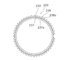
(b) 前記参考例では、2分割の分割部材29a,29bとばね部材30とにより摩擦部材を構成したが、1つの部材で摩擦部材を構成してもよい。たとえば、図18及び図19に示すように、摩擦部材229は、一部が切り欠かれ弾性力を有する環状部材230を有し、環状部材230は弾性力により筒状部材40の環状溝40dに圧接されている。環状部材230は、内周に摩擦部237aが形成され一部が切り欠かれ弾性力を有する環状の板ばね部237と、板ばね部237の外周の径方向外方に放射状に突出して設けられ係合部238aを形成する複数の突出部238とを有している。このような構成の自身の弾性力で環状溝40dに装着された分割されない摩擦部材229であってもよい。 (B) In the reference example , the friction member is formed by the two divided members 29a and 29b and the spring member 30, but the friction member may be formed by one member. For example, as shown in FIGS. 18 and 19, the friction member 229 includes an annular member 230 that is partially cut out and has an elastic force, and the annular member 230 is formed in the annular groove 40 d of the tubular member 40 by the elastic force. It is in pressure contact. The annular member 230 is provided with an annular leaf spring portion 237 having a frictional portion 237a formed on the inner periphery and partially cut away and having an elastic force, and radially projecting radially outward of the outer periphery of the leaf spring portion 237. And a plurality of projecting portions 238 forming the engaging portion 238a. The non-divided friction member 229 attached to the annular groove 40d with its own elastic force having such a configuration may be used.

〔他の実施形態〕
(c) 前記実施形態では、摩擦リング130としてOリングを用いたが、摩擦リングはOリングに限定されない。
[Other Embodiments]
(C) Although the O-ring is used as the friction ring 130 in the embodiment, the friction ring is not limited to the O-ring.

(d) 前記実施形態では、制動レバー17,117をリールボディ2a,102aに揺動自在に装着したが、図20に示すように、制動レバー217を脚部に202bに設けた支持軸233に揺動自在に装着してもよい。この場合も制動レバー217を制動解除方向に付勢するコイルばね219は、支持軸233の第1操作部217c側に配置されている。このような構成では、制動レバー217の先端の操作部分である第1操作部217cに揺動支点である第2軸Y’が接近するともに、制動作用する制動作用部217bが第2軸Y’から離れることにより、制動作用部217bでの移動量に対して第1操作部217cの移動量を少なくすることができる。このため、釣り竿と制動レバー217との間隔を狭くすることができ、リール全体を小型化することができる。また、脚部202bに制動レバー217を装着することにより、筐体部202fに制動レバー217の支持軸233を設ける必要がなくなり、筐体部202fをコンパクトにすることができる。   (D) In the above embodiment, the brake levers 17 and 117 are swingably mounted on the reel bodies 2a and 102a. However, as shown in FIG. 20, the brake lever 217 is attached to the support shaft 233 provided on the leg 202b. You may mount so that rocking is possible. Also in this case, the coil spring 219 that urges the brake lever 217 in the brake release direction is disposed on the first operating portion 217 c side of the support shaft 233. In such a configuration, the second axis Y ′ that is the swing fulcrum approaches the first operation part 217c that is the operation part at the tip of the brake lever 217, and the braking action part 217b that acts as a brake acts on the second axis Y ′. By moving away from the movement amount, the movement amount of the first operation portion 217c can be reduced relative to the movement amount of the braking action portion 217b. For this reason, the space | interval of a fishing rod and the brake lever 217 can be narrowed, and the whole reel can be reduced in size. Further, by mounting the brake lever 217 on the leg 202b, it is not necessary to provide the support shaft 233 of the brake lever 217 on the housing 202f, and the housing 202f can be made compact.

本発明の参考例によるスピニングリールの側面断面図。The side sectional view of the spinning reel by the reference example of the present invention. その制動部の断面拡大図。The cross-sectional enlarged view of the braking part. 図1のIII−III断面図。III-III sectional drawing of FIG. 制動レバーの操作部分の平面部分図。FIG. 6 is a partial plan view of an operation portion of a brake lever. 制動状態の各レバーと制動円筒の状態を示す断面模式図。The cross-sectional schematic diagram which shows the state of each lever and brake cylinder of a braking state. 所定制動状態の各レバーと制動円筒の状態を示す断面模式図。The cross-sectional schematic diagram which shows the state of each lever and brake cylinder of a predetermined braking state. 制動解除状態における各レバーと制動円筒の状態を示す断面模式図。The cross-sectional schematic diagram which shows the state of each lever and a brake cylinder in a brake release state. 制動解除状態と所定制動状態での第2レバー部材の動作を示す模式図。The schematic diagram which shows operation | movement of the 2nd lever member in a braking release state and a predetermined braking state. 摩擦部材構造を示す断面拡大図。The cross-sectional enlarged view which shows the structure of a friction member. 摩擦部材の構造を示す平面部分図。The fragmentary top view which shows the structure of a friction member. 摩擦部材の正面図。The front view of a friction member. 本発明の一実施形態の図1に相当する図。 The figure equivalent to FIG. 1 of one Embodiment of this invention . その図2に相当する図。The figure equivalent to the FIG. そのスプールの正面図Front view of the spool 図14のXV−XV断面図。XV-XV sectional drawing of FIG. その図3に相当する図。The figure equivalent to the FIG. その図8に相当する図。The figure equivalent to the FIG. 他の参考例の図9に相当する図。The figure equivalent to FIG. 9 of another reference example . その図11に相当する図。The figure equivalent to the FIG. の実施形態の図12に相当する図。The figure equivalent to FIG. 12 of other embodiment.

2,102 リール本体
2a,102a リールボディ
3,103 ロータ
6,106 レバーブレーキ機構
16,116 制動部
17,117,217 制動レバー
8 補助レバー
21,121 所定制動部
27.127 第2レバー部材
29,129 摩擦部材
29a,29b 分割部材
30 ばね部材
37,37a 摩擦部
38,38a 係合部
38a 係合凹部
40 筒状部材
37 板ばね部
38 突出部
2,102 reel body 2a, 102a reel body 3,103 rotor 6,106 lever brake mechanism 16 and 116 brake 17,117,217 brake lever 1 8 auxiliary lever 21, 121 a predetermined braking section 27.127 second lever member 29,129 Friction member 29a, 29b Split member 30 Spring member 37, 2 37a Friction part 38, 2 38a Engagement part 38a Engagement recess 40 Cylindrical member
2 37 leaf spring
2 38 Protrusion

Claims (10)

スピニングリールのリール本体に回転自在に装着されたロータの糸繰り出し方向の回転を制動するスピニングリールのロータ制動装置であって、
前記ロータの糸繰り出し方向の回転を伝達するワンウェイクラッチと、
円筒部を有し、前記ワンウェイクラッチから伝達された前記ロータの糸繰り出し方向の回転に連動して回転する回転部材と、
前記回転部材に相対回転可能に装着され前記円筒部の外周面に摩擦係合する摩擦部材、及び前記摩擦部材に係合して前記摩擦部材の回転を禁止し前記摩擦部材を前記回転部材に対して相対回転させて前記ロータの糸繰り出し方向の回転を制動する制動位置と前記摩擦部材から離反して前記摩擦部材の回転を許可し制動解除する離反位置とに切換可能に前記リール本体に装着された切換動作部を有する所定制動部と、を備え、
前記摩擦部材と前記円筒部との間に装着された少なくとも1つの摩擦リングをさらに備え、
前記摩擦部材は、前記摩擦リングを介して前記円筒部の外周面と摩擦係合している、スピニングリールのロータ制動装置。
A spinning reel rotor braking device that brakes rotation of a rotor that is rotatably mounted on a reel body of a spinning reel in a yarn unwinding direction,
A one-way clutch that transmits the rotation of the rotor in the yarn unwinding direction;
A rotating member that has a cylindrical portion and rotates in conjunction with the rotation of the rotor in the yarn unwinding direction transmitted from the one-way clutch;
A friction member that is mounted on the rotating member so as to be relatively rotatable and frictionally engages with an outer peripheral surface of the cylindrical portion, and that the friction member engages with the friction member to prohibit the rotation of the friction member. Are mounted on the reel body so as to be switchable between a braking position for braking the rotation of the rotor in the yarn unwinding direction and a separating position for allowing the friction member to rotate and releasing the braking. A predetermined braking unit having a switching operation unit ,
Further comprising at least one friction ring mounted between the friction member and the cylindrical portion;
The spinning brake rotor braking device , wherein the friction member is frictionally engaged with the outer peripheral surface of the cylindrical portion via the friction ring .
前記回転部材は円筒部を有し、
前記摩擦部材は、前記円筒部の外周面に摩擦係合して装着されている、請求項1に記載のスピニングリールのロータ制動装置。
The rotating member has a cylindrical portion;
2. The spinning reel rotor braking device according to claim 1, wherein the friction member is frictionally engaged with an outer peripheral surface of the cylindrical portion.
前記円筒部の外周面には、前記摩擦部材を装着するための環状装着溝が形成されている、請求項2に記載のスピニングリールのロータ制動装置。   The spinning reel rotor braking device according to claim 2, wherein an annular mounting groove for mounting the friction member is formed on an outer peripheral surface of the cylindrical portion. 前記リール本体は、釣り竿に装着される装着部と、前記装着部と間隔を隔てて配置されたリールボディと、前記装着部と前記リールボディとを連結する脚部とを有し、
前記装着部と接近・離反する方向に揺動自在に前記リール本体に装着され、前記装着部に対して接近・離反する制動操作部と、前記制動操作部と揺動軸芯を挟んで配置され前記円筒部を押圧する制動作用部とを有し、前記ロータの糸繰り出し方向の回転を可変に制動するための制動レバーをさらに備える、請求項1から3のいずれか1項に記載のスピニングリールのロータ制動装置。
The reel body has a mounting portion mounted on the fishing Ri rod, a reel body which is arranged at the mounting portion and the distance, and a leg portion connecting the reel body and the mounting portion,
It is mounted on the reel body so as to be swingable in a direction approaching / separating from the mounting unit, and is arranged with a braking operation unit approaching / separating from the mounting unit, and sandwiching the braking operation unit and a swing axis. The spinning reel according to any one of claims 1 to 3, further comprising a brake lever that has a braking action portion that presses the cylindrical portion, and variably brakes rotation of the rotor in a yarn unwinding direction. Rotor braking device.
前記制動レバーは、前記リールボディに揺動自在に装着されている、請求項4に記載のスピニングリールのロータ制動装置。   The spinning brake rotor braking device according to claim 4, wherein the brake lever is swingably attached to the reel body. 前記リールボディは、内部に空間を有する筐体部と、前記筐体部を塞ぐ蓋部とを有し、
前記制動レバーは、前記蓋部を前記筐体部に取り付けるねじ部材に揺動自在に装着されている、請求項5に記載のスピニングリールのロータ制動装置。
The reel body has a housing portion having a space inside, and a lid portion that closes the housing portion,
The spinning brake rotor braking device according to claim 5, wherein the brake lever is swingably attached to a screw member that attaches the lid portion to the housing portion.
前記制動レバーは、前記脚部に揺動自在に装着されている、請求項4に記載のスピニングリールのロータ制動装置。 The spinning brake rotor braking device according to claim 4, wherein the brake lever is swingably attached to the leg portion. 先端が前記制動操作部と前記装着部から離反する方向に間隔を隔てて配置され前記リール本体に揺動自在に装着され前記所定制動部を切換操作するための切換操作部をさらに備え、
前記切換動作部は、前記切換操作部の基端に係合し、前記切換操作部の揺動に応じて前記制動位置と前記離反位置とに移動する、請求項4から7のいずれか1項に記載のスピニングリールのロータ制動装置。
A switching operation portion for switching the predetermined braking portion, the tip of which is disposed at an interval in a direction away from the braking operation portion and the mounting portion and is swingably mounted on the reel body;
The switching operation unit engages with a base end of the switching operation unit, and moves to the braking position and the separation position according to the swinging of the switching operation unit. The spinning reel rotor braking device according to claim 1.
前記切換操作部は、前記装着部から離反する方向に揺動すると前記切換動作部が制動位置に移動し、制動位置に前記切換動作部が配置された状態で前記制動操作部が前記装着部に接近する方向に揺動すると、前記制動操作部に連動して前記装着部に接近する方向に揺動し、前記切換動作部が前記離反位置に戻る、請求項8に記載のスピニングリールのロータ制動装置。   When the switching operation portion swings in a direction away from the mounting portion, the switching operation portion moves to a braking position, and the braking operation portion is moved to the mounting portion in a state where the switching operation portion is arranged at the braking position. 9. The spinning reel rotor braking according to claim 8, wherein when the swinging portion swings in the approaching direction, the swinging operation portion swings in a direction approaching the mounting portion and the switching operation portion returns to the separation position. apparatus. 前記円筒部の外周面には、前記摩擦リングを装着するための少なくとも1つの環状装着溝を有する、請求項1から9のいずれか1項に記載のスピニングリールのロータ制動装置。 10. The spinning reel rotor braking device according to claim 1, wherein at least one annular mounting groove for mounting the friction ring is provided on an outer peripheral surface of the cylindrical portion. 10.
JP2004194653A 2004-06-30 2004-06-30 Spinning reel rotor braking device Active JP4451734B2 (en)

Priority Applications (4)

Application Number Priority Date Filing Date Title
JP2004194653A JP4451734B2 (en) 2004-06-30 2004-06-30 Spinning reel rotor braking device
KR1020050050839A KR101191077B1 (en) 2004-06-30 2005-06-14 Rotor brake device for spinning reel
TW094119864A TW200608885A (en) 2004-06-30 2005-06-15 Rotor-brake device for spinning reel
CN2005100798722A CN1714635B (en) 2004-06-30 2005-06-29 Braking device of fishing reel wheel rotor

Applications Claiming Priority (1)

Application Number Priority Date Filing Date Title
JP2004194653A JP4451734B2 (en) 2004-06-30 2004-06-30 Spinning reel rotor braking device

Publications (3)

Publication Number Publication Date
JP2006014640A JP2006014640A (en) 2006-01-19
JP2006014640A5 JP2006014640A5 (en) 2007-06-28
JP4451734B2 true JP4451734B2 (en) 2010-04-14

Family

ID=35789425

Family Applications (1)

Application Number Title Priority Date Filing Date
JP2004194653A Active JP4451734B2 (en) 2004-06-30 2004-06-30 Spinning reel rotor braking device

Country Status (4)

Country Link
JP (1) JP4451734B2 (en)
KR (1) KR101191077B1 (en)
CN (1) CN1714635B (en)
TW (1) TW200608885A (en)

Families Citing this family (5)

* Cited by examiner, † Cited by third party
Publication number Priority date Publication date Assignee Title
JP4863716B2 (en) * 2006-01-12 2012-01-25 株式会社シマノ Spinning reel rotor braking device
JP4901710B2 (en) * 2007-12-18 2012-03-21 株式会社シマノ Spinning reel drag knob assembly
JP6247843B2 (en) * 2013-06-21 2017-12-13 株式会社シマノ Spinning reel for fishing and brake operation lever of rotor braking device thereof
JP6965074B2 (en) * 2017-09-22 2021-11-10 株式会社シマノ Spinning reel rotor braking device
JP6856738B2 (en) * 2019-12-19 2021-04-07 株式会社シマノ Spinning reel

Also Published As

Publication number Publication date
CN1714635A (en) 2006-01-04
JP2006014640A (en) 2006-01-19
TWI345956B (en) 2011-08-01
TW200608885A (en) 2006-03-16
KR20060048352A (en) 2006-05-18
KR101191077B1 (en) 2012-10-15
CN1714635B (en) 2011-08-24

Similar Documents

Publication Publication Date Title
JP4863716B2 (en) Spinning reel rotor braking device
JP6039454B2 (en) Spinning reel thread locker and spinning reel spool using the same
US20070284466A1 (en) Drag device for spinning reel
JP2010119345A (en) Drag adjusting device for dual-bearing reel
JP2007185130A5 (en)
JP4451734B2 (en) Spinning reel rotor braking device
JP2007312703A5 (en)
JP5588152B2 (en) Spinning reel rotor braking device
JP3977672B2 (en) Spinning reel rotor braking device
KR100877308B1 (en) Spinning Reel
JP6261884B2 (en) Spinning reel for fishing and brake operation lever of rotor braking device thereof
JP6247115B2 (en) Spinning reel
JP5460250B2 (en) Spinning reel rotor braking device
JP4500629B2 (en) Sounding mechanism of spinning reel
JP4006292B2 (en) Spinning reel lever brake mechanism
JP5624069B2 (en) Spinning reel and spinning reel drag switching device
JP2015159757A5 (en)
JP2003125682A (en) Spinning reel
JP4462754B2 (en) Spinning reel
JP2013146245A5 (en)
KR20110019701A (en) Brake device for spinning reel rotor
KR100905294B1 (en) Spinning Reel
JP2003088280A (en) Reel body of spinning reel
JP6247843B2 (en) Spinning reel for fishing and brake operation lever of rotor braking device thereof
JP4381896B2 (en) Sounding mechanism of spinning reel

Legal Events

Date Code Title Description
A521 Request for written amendment filed

Free format text: JAPANESE INTERMEDIATE CODE: A523

Effective date: 20070511

A621 Written request for application examination

Free format text: JAPANESE INTERMEDIATE CODE: A621

Effective date: 20070511

A977 Report on retrieval

Free format text: JAPANESE INTERMEDIATE CODE: A971007

Effective date: 20091126

A131 Notification of reasons for refusal

Free format text: JAPANESE INTERMEDIATE CODE: A131

Effective date: 20091201

A521 Request for written amendment filed

Free format text: JAPANESE INTERMEDIATE CODE: A523

Effective date: 20091217

RD02 Notification of acceptance of power of attorney

Free format text: JAPANESE INTERMEDIATE CODE: A7422

Effective date: 20091217

TRDD Decision of grant or rejection written
A01 Written decision to grant a patent or to grant a registration (utility model)

Free format text: JAPANESE INTERMEDIATE CODE: A01

Effective date: 20100119

A01 Written decision to grant a patent or to grant a registration (utility model)

Free format text: JAPANESE INTERMEDIATE CODE: A01

A61 First payment of annual fees (during grant procedure)

Free format text: JAPANESE INTERMEDIATE CODE: A61

Effective date: 20100128

R150 Certificate of patent or registration of utility model

Ref document number: 4451734

Country of ref document: JP

Free format text: JAPANESE INTERMEDIATE CODE: R150

Free format text: JAPANESE INTERMEDIATE CODE: R150

FPAY Renewal fee payment (event date is renewal date of database)

Free format text: PAYMENT UNTIL: 20130205

Year of fee payment: 3

FPAY Renewal fee payment (event date is renewal date of database)

Free format text: PAYMENT UNTIL: 20140205

Year of fee payment: 4

R250 Receipt of annual fees

Free format text: JAPANESE INTERMEDIATE CODE: R250

R250 Receipt of annual fees

Free format text: JAPANESE INTERMEDIATE CODE: R250

R250 Receipt of annual fees

Free format text: JAPANESE INTERMEDIATE CODE: R250

R250 Receipt of annual fees

Free format text: JAPANESE INTERMEDIATE CODE: R250

R250 Receipt of annual fees

Free format text: JAPANESE INTERMEDIATE CODE: R250

R250 Receipt of annual fees

Free format text: JAPANESE INTERMEDIATE CODE: R250

R250 Receipt of annual fees

Free format text: JAPANESE INTERMEDIATE CODE: R250

R250 Receipt of annual fees

Free format text: JAPANESE INTERMEDIATE CODE: R250

R250 Receipt of annual fees

Free format text: JAPANESE INTERMEDIATE CODE: R250

R250 Receipt of annual fees

Free format text: JAPANESE INTERMEDIATE CODE: R250

R250 Receipt of annual fees

Free format text: JAPANESE INTERMEDIATE CODE: R250