以下に、本発明に係る実施形態について添付図面を参照しながら詳細に説明する。この説明において、具体的な形状、材料、数値、方向等は、本発明の理解を容易にするための例示であって、用途、目的、仕様等にあわせて適宜変更することができる。また、以下において複数の実施形態や変形例などが含まれる場合、それらの特徴部分を適宜に組み合わせて用いることは当初から想定されている。
図1は、本発明の一実施形態である電源システムの構成を示す回路図である。電源システム1は、第1の直流電源10aおよび第2の直流電源10bと、負荷30と、制御装置40と、電力変換器50とを備える。
本実施形態において、各直流電源10a,10bは、リチウムイオン電池やニッケル水素電池のような二次電池、または、電気二重層キャパシタやリチウムイオンキャパシタ等の出力特性に優れた直流電圧源要素により構成される。ここで、直流電源10aが「第1の直流電源」に対応し、直流電源10bが「第2の直流電源」に対応する。
直流電源10a,10bは、同種および同容量の直流電源によって構成することも可能であり、特性および/容量が異なる直流電源によって構成することも可能である。
電力変換器50は、直流電源10a,10bと、電力線20との間に接続されている。電力変換器50は、負荷30と接続された電力線20上の直流電圧(以下、出力電圧VHとも称する)を電圧指令値VH*に従って制御する。すなわち、電力線20は、直流電源10a,10bに対して共通に設けられる。
負荷30は、電力変換器50の出力電圧VHを受けて動作する。電圧指令値VH*は、負荷30の動作に適した電圧に設定される。電圧指令値VH*は、負荷30の動作状態(例えば、トルク、回転数等)に応じて可変に設定される。また、負荷30は、回生発電等によって、直流電源10a,10bの充電電力を発生可能に構成されてもよい。
電力変換器50は、スイッチング素子S1〜S4と、リアクトルL1,L2とを含む。本実施形態において、スイッチング素子S1〜S4としては、例えばIGBT(Insulated Gate Bipolar Transistor)等を用いることができる。スイッチング素子S1〜S4には、ダイオードD1〜D4が逆並列に接続されている。
スイッチング素子S1〜S4は、制御信号SG1〜SG4にそれぞれ応答して、オンオフを制御することが可能である。すなわち、スイッチング素子S1〜S4は、制御信号SG1〜SG4がハイレベル(以下、Hレベル)のときオンする一方で、ローレベル(以下、Lレベル)のときにオフする。
スイッチング素子S1は、電力線20とノードN1との間に電気的に接続されている。リアクトルL2は、ノードN1と直流電源10bの正極端子との間に接続される。リアクトルL2を流れる電流ILbは、電流センサ12bにより検出されて、制御装置40へ入力される。スイッチング素子S2は、ノードN1およびノードN2の間に電気的に接続されている。リアクトルL1はノードN2と直流電源10aの正極端子との間に接続される。リアクトルL1に流れる電流ILaは、電流センサ12aによって検出されて、制御装置40へ入力される。
スイッチング素子S3は、ノードN2およびN3の間に電気的に接続されている。ノードN3は、直流電源10bの負極端子と電気的に接続される。スイッチング素子S4は、ノードN3および接地配線21の間に電気的に接続されている。接地配線21は、負荷30と、直流電源10aの負極端子とに電気的に接続されている。
図1から理解されるように、電力変換器50は、直流電源10aおよび直流電源10bの各々に対応して昇圧チョッパ回路を備えた構成となっている。すなわち、直流電源10aに対しては、スイッチング素子S1,S2を上アーム素子とする一方で、スイッチング素子S3,S4を下アーム素子とする直流双方向の第1の昇圧チョッパ回路が構成される。同様に、直流電源10bに対しては、スイッチング素子S1,S4を上アーム素子とする一方で、スイッチング素子S2,S3を下アーム素子とする電流双方向の第2の昇圧チョッパ回路が構成される。
そして、第1の昇圧チョッパ回路によって、直流電源10aおよび電力線20の間に形成される電力変換経路と、第2の昇圧チョッパ回路によって、直流電源10bおよび電力線20の間に形成される電力変換経路との両方に、スイッチング素子S1〜S4が含まれる。なお、図1の構成において、スイッチング素子S1〜S4が電力変換器50における「複数のスイッチング素子」に対応する。
制御装置40は、負荷30への出力電圧VHを制御するために、スイッチング素子S1〜S4のオンオフを制御する制御信号SG1〜SG4を生成する。制御装置40には、電圧センサ11aによって検出される直流電源10aの電圧Va、図示しない電流センサによって検出される直流電源10aを流れる電流Ia、電圧センサ11bによって検出される直流電源10bの電圧Vb、図示しない電流センサによって検出される直流電源10bの電流Ibが入力される。また、制御装置40には、図示しない温度センサによってそれぞれ検出される直流電源10a,10bの温度Ta,Tbも入力される。さらに、制御装置40には、図示しない電圧センサによって検出される電力変換器50の出力電圧VHも入力される。
なお、直流電源10aとリアクトルL1との間で補機類への電力分配線が接続されていない場合、リアクトルL1を流れる電流ILaは直流電源10aの電流Iaに等しいとみなせる。同様に、直流電源10bとリアクトルL2との間で補機類への電力分配線が接続されていない場合には、リアクトルL2を流れる電流ILbは直流電源10bの電流Ibに等しいとみなせる。
図2は、負荷30の構成例を示す概略図である。負荷30は、例えば電動車両の走行用電動機を含むように構成される。負荷30は、平滑コンデンサCHと、インバータ32と、モータジェネレータ35と、動力伝達ギヤ36と、駆動輪37とを含む。
モータジェネレータ35は、車両駆動力を発生するための走行用電動機であり、例えば、複数相の永久磁石型同期電動機で構成される。モータジェネレータ35の出力トルクは、減速機や動力分割機構によって構成される動力伝達ギヤ36を経由して、駆動輪37へ伝達される。駆動輪37に伝達されたトルクにより電動車両が走行する。また、モータジェネレータ35は、電動車両の回生制動時には、駆動輪37の回転力によって発電する。この発電電力は、インバータ32によって交流電力から直流電力に変換され、電源システム1に含まれる直流電源10a,10bの充電電力として用いることができる。
モータジェネレータの他にエンジン(図示せず)を搭載したハイブリッド自動車では、エンジンおよびモータジェネレータ35を協調的に動作させることによって、電動車両に必要な車両駆動力が発生される。この際にも、エンジンの回転による発電電力を用いて直流電源10a,10bを充電することも可能である。
このように、電動車両は、走行用電動機を搭載する車両を包括的に示すものであり、エンジンおよび電動機により車両駆動力を発生するハイブリッド自動車と、エンジンを搭載しない電気自動車および燃料電池自動車の両方を含むものである。
(電力変換器の動作モード)
電力変換器50は、直流電源10a,10bと電力線20との間での直流電力変換の態様が異なる複数の動作モードを有する。
図3には、電力変換器50が有する複数の動作モードが示される。図3に示すように、動作モードは、スイッチング素子S1〜S4の周期的なオンオフ制御に伴って直流電源10aおよび/または10bの出力電圧を昇圧する「昇圧モード(B)」と、スイッチング素子S1〜S4のオンオフを固定して直流電源10aおよび/または10bを電力線20に電気的に直結で接続する「直結モード(D)」とに大別される。
昇圧モードには、直流電源10aおよび10bと電力線20との間で並列なDC/DC変換を行う「パラレル昇圧モード(以下、PBモード)」と、直列接続された直流電源10aおよび10bと電力線20との間でDC/DC変換を行う「シリーズ昇圧モード(以下、SBモード)」と、直流電源10aおよび10bの一方と電力線20との間でDC/DC変換を行うとともに直流電源10aおよび10bの他方と電力線20との間を一方の直流電源に対して並列にかつ電力線20へ直結接続する「パラレル昇圧直結モード(以下、PBDモード)」が含まれる。なお、以下においてPBDモードは、一方の直流電源に対する昇圧動作を伴う動作モードであるため、「昇圧モード(B)」に大別されるものとして説明する。
昇圧モードには、さらに、直流電源10aのみを用いて電力線20との間でDC/DC変換を行う「直流電源10aによる単独モード(以下、aBモード)」と、直流電源10bのみを用いて電力線20との間でDC/DC変換を行う「直流電源10bによる単独モード(以下、bBモード)」とが含まれる。aBモードでは、直流電源10bは、出力電圧VHが直流電源10bの電圧よりも高く制御されている限りにおいて、電力線20と電気的に切り離された状態を維持されて不使用とされる。同様に、bBモードでは、直流電源10aは、出力電圧VHが直流電源10aの電圧よりも高く制御されている限りにおいて、電力線20と電気的に切り離された状態を維持されて不使用とされる。
昇圧モードに含まれるPBモード、SBモード、aBモード、およびbBモードの各々では、電力線20の出力電圧VHは、電圧指令値VH*に従って制御される。これらの各モードにおけるスイッチング素子S1〜S4の制御については後述する。
直結モードには、直流電源10aおよび10bを電力線20に対して並列に接続した状態を維持する「パラレル直結モード(以下、PDモード)」と、直流電源10aおよび10bを電力線20に対して直列に接続した状態を維持する「シリーズ直結モード(以下、SDモード)」とが含まれる。
PDモードは、スイッチング素子S1,S2,S4がオンに固定される一方で、スイッチング素子S3がオフに固定される。これにより、出力電圧VHは、直流電源10a,10bの出力電圧Va,Vb(厳密にはVa,Vbのうちの高い方)と同等になる。Va,Vb間の電圧差は直流電源10a,10b間に短絡電流を生じさせるので、当該電圧差が小さいときに限定してPDモードを適用することができる。
SDモードでは、スイッチング素子S2,S4がオフに固定される一方で、スイッチング素子S1,S3がオンに固定される。これにより、出力電圧VHは、直流電源10a,10bの出力電圧Va,Vbの和と同等になる(VH=Va+Vb)。
また、直結モードには、直流電源10aのみを電力線20と電気的に接続する「直流電源10aの直結モード(以下、aDモード)」と、直流電源10bのみを電力線20と電気的に接続する「直流電源10bの直結モード(以下、bDモード)」とが含まれる。
aDモードでは、スイッチング素子S1,S2がオンに固定される一方で、スイッチング素子S3,S4がオフに固定される。これにより、直流電源10bは電力線20から切り離された状態となり、出力電圧VHは、直流電源10aの電圧Vaと同等になる(VH=Va)。aDモードでは、直流電源10bは、電力線20と電気的に切り離された状態を維持されて不使用とされる。なお、Vb>Vaの状態でaDモードを適用すると、スイッチング素子S2を介して直流電源10bから10aに短絡電流が生じることになる。そのため、aDモードの適用には、Va>Vbが必要条件となる。
同様に、bDモードでは、スイッチング素子S1,S4がオンに固定される一方で、スイッチング素子S2,S3がオフに固定される。これにより、直流電源10aは電力線20から切り離された状態となり、出力電圧VHは、直流電源10bの電圧Vbと同等になる(VH=Vb)。bDモードでは、直流電源10aは、電力線20と電気的に切り離された状態に維持されて不使用とされる。なお、Va>Vbの状態でbDモードを適用すると、ダイオードD2を介して直流電源10aから10bに短絡電流が流れることになる。そのため、bDモードの適用には、Vb>Vaが必要条件となる。
直結モードに含まれるPDモード、SDモード、aDモードおよびbDモードの各々では、電力線20の出力電圧VHは、直流電源10a,10bの電圧Va,Vbに依存して決まるため、直接制御することができなくなる。そのため、直結モードに含まれる各モードでは、出力電圧VHが負荷30の動作に適した電圧に設定できなくなることにより、負荷30での電力損失が増加する可能性がある。
一方で、直結モードでは、スイッチング素子S1〜S4がオンオフされないため、電力変換器50の電力損失が大幅に抑制される。したがって、負荷30の動作状態によっては、直結モードの適用によって、負荷30の電力損失増加よりも電力変換器50での電力損失減少量が多くなることにより、電源システム1全体での電力損失を抑制できる可能性がある。
このような点は本実施形態における特有の動作モードであるPBDモードについても同様である。すなわち、PBDモードでは、一方の直流電源10aまたは10bが電力線20に対して他方の直流電源10bまたは10aと並列にかつ直結接続されるため、出力電圧VHが直流電源10aまたは10bの電源VaまたはVbとなって直接制御することができない。しかし、スイッチング素子S1〜S4のうちの直結接続される直流電源に対応する2つのスイッチング素子がオンオフされないため、電力変換器50の電力損失が大幅に抑制され、負荷30の動作状態によってはPBDモードの適用により電源システム1全体での電力損失を抑制できる可能性がある。
図3において、PBモード、SBモード、aBモード、bBモード、PDモード、SDモード、aDモードおよびbDモードが「複数の動作モード」に対応し、PBDモードが「選択された動作モード」に対応する。
本実施形態の電源システム1では、例えば、直流電源10aを高出力型の電源で構成する一方、直流電源10bを高容量型の電源で構成するのが好ましい。これにより、電動車両において例えばユーザのアクセル操作によって急加速が要求された場合には高出力型の直流電源10aからの出力で対応し、他方、電動車両において継続的な高速定常走行等の比較的低パワーが長時間要求されるときは高容量型の直流電源10bからの出力によって対応することができる。このような電動車両では、高容量型の直流電源10bに蓄積されたエネルギーを長時間にわたって使用することによって、電気エネルギーによる走行距離を延ばすことができるとともに、ユーザのアクセル操作に対応した加速性能を速やかに確保することができる。
しかし、直流電源がバッテリによって構成される場合、低温時に出力特性が低下する可能性や、高温時に劣化進行を抑制するために充放電が制限される可能性がある。特に、電動車両では、搭載位置の差異によって、直流電源10a,10bの間に温度差が発生するケースも生じる。したがって、電源システム1では、各直流電源10a,10bの充放電が制限される状態において、制限値を超える過剰な充放電が生じないように負荷30の要求電力に対応する電力線20の出力電力PHを制限する処理を実行する。その詳細については、後述する。
(PB動作モードでの昇圧動作)
次に、図4及び図5を参照してPB動作モードでの昇圧動作について詳細に説明する。図4には、PBモードにおける直流電源10aに対するDC/DC変換(昇圧動作)が示される。図4(a)に示すように、スイッチング素子S3,S4のペアをオンし、スイッチング素子S1,S2のペアをオフすることによって、リアクトルL1にエネルギーを蓄積するための電流経路80が形成される。これにより、昇圧チョッパ回路の下アーム素子がオンした状態が形成される。
これに対し、図4(b)に示すように、スイッチング素子S3,S4のペアをオフするとともに、スイッチング素子S1,S2のペアをオンすることによって、リアクトルL1の蓄積エネルギーを直流電源10aのエネルギーとともに出力するための電流経路81が形成される。これにより、昇圧チョッパ回路の上アーム素子がオンした状態が形成される。このとき、電流経路81ではダイオードD1,D2を通って電流が流れるため、スイッチング素子S1,S2は負荷30からの回生電力を直流電源10aに充電する電流経路を形成するスイッチとして機能する。
上記のようにスイッチング素子S3,S4のペアがオンされる一方で、スイッチング素子S1,S2の少なくとも一方がオフされている第1の期間と、スイッチング素子S1,S2のペアがオンされる一方でスイッチング素子S3,S4のペアの少なくとも一方がオフされている第2の期間とを交互に繰り返すことにより、直流電源10aに対する昇圧チョッパ回路が構成される。ここで、図4に示されるDC/DC変換動作では、直流電源10bへの電流流通経路がないため、直流電源10a,10bは互いに非干渉である。すなわち、直流電源10a,10bに対する電力の入出力を独立に制御することができる。
このようなDC/DC変換において、直流電源10aの電圧Vaと、電力線20の出力電圧VHとの間には、下記(1)式に示す関係が成立する。(1)式では、スイッチング素子S3,S4のペアがオンされる期間のデューティ比をDaとする。
VH=1/(1−Da)・Va (1)
図5には、PBモードにおける直流電源10bに対するDC/DC変換(昇圧動作)が示される。図5(a)に示すように、スイッチング素子S2,S3のペアをオンし、スイッチング素子S1,S4のペアをオフすることによって、リアクトルL2にエネルギーを蓄積するための電流経路82が形成される。これにより、昇圧チョッパ回路の下アーム素子がオンした状態が形成される。
これに対し、図5(b)に示すように、スイッチング素子S2,S3のペアをオフするとともに、スイッチング素子S1,S4のペアをオンすることによって、リアクトルL2の蓄積エネルギーを直流電源10bのエネルギーとともに出力するための電流経路83が形成される。これにより、昇圧チョッパ回路の上アーム素子をオンした状態が形成される。このとき、電流経路83ではダイオードD1を通って電流が流れるため、スイッチング素子S1は負荷30からの回生電力を直流電源10bに充電する電流経路を形成するスイッチとして機能する。
スイッチング素子S2,S3のペアがオンされる一方でスイッチング素子S1,S4の少なくとも一方がオフされている第1の期間と、スイッチング素子S1,S4のペアがオンされる一方でスイッチング素子S2,S3の少なくとも一方がオフされている第2の期間とが交互に繰り返されることにより、直流電源10bに対する昇圧チョッパ回路が構成される。ここで、図5に示されるDC/DC変換動作では、直流電源10aへの電流流通経路がないため、直流電源10a,10bは互いに非干渉である。すなわち、直流電源10a,10bに対する電力の入出力を独立に制御することができる。
このようなDC/DC変換において、直流電源10bの電圧Vbと、電力線20の出力電圧VHとの間には、下記(2)式に示す関係が成立する。(2)式では、スイッチング素子S2,S3がオンされる期間のデューティ比をDbとする。
VH=1/(1−Db)・Vb (2)
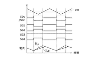
図6には、PBモードにおけるスイッチング素子の制御動作例を説明するための波形図が示される。図6には、直流電源10aのPWM(Pulse Width Modulation)制御に用いられるキャリア波CWaと、直流電源10bのPWM制御に用いられるキャリア波CWbとは、同一周波数かつ同一位相であるときの例が示される。
図6を参照すると、例えば、PBモードでは、直流電源10a,10bの一方の出力を、出力電圧VHの電圧偏差ΔVH(ΔVH=VH*−VH)を補償するように制御(電圧制御)するとともに、直流電源10a,10bの他方の出力を、電流Ia,Ibの電流偏差を補償するように制御するように制御(電流制御)することができる。この際、電流制御の指令値(Ia*またはIb*)は、当該電源の出力電力を制御するように設定することができる。
一例として、直流電源10bの出力を電圧制御する一方で、直流電源10aの出力を電流制御するようにすると、デューティ比Daは電流偏差ΔIa(ΔIa=Ia*−Ia)に基づいて演算される一方で、デューティ比Dbは電圧偏差ΔVHに基づいて演算される。
直流電源10aの出力を制御するためのデューティ比Daと、キャリア波CWaとの電圧比較に基づいて、制御パルス信号SDaが生成される。同時に、直流電源10bの出力を制御するためのデューティ比Dbとキャリア波CWbとの比較に基づいて、制御パルス信号SDbが生成される。制御パルス信号/SDa,/SDbは、制御パルス信号SDa,SDbの反転信号である。
図7に示すように、制御信号SG1〜SG4は、制御パルス信号SDa(/SDa)およびSDb(/SDb)の論理演算に基づいて設定される。具体的には、スイッチング素子S1は、図4および図5の昇圧チョッパ回路の各々で上アーム素子を構成する。したがって、スイッチング素子S1のオンオフを制御する制御信号SG1は、制御パルス信号/SDaおよび/SDbの論理和によって生成される。
スイッチング素子S2は、図4の昇圧チョッパ回路では上アーム素子を構成し、図5の昇圧チョッパ回路では下アーム素子を構成する。したがって、スイッチング素子S2のオンオフを制御する制御信号SG2は、制御パルス信号/SDaおよびSDbの論理和によって生成される。
スイッチング素子S3は、図4および図5の昇圧チョッパ回路の各々で下アーム素子を構成する。したがって、スイッチング素子S3のオンオフを制御する制御信号SG3は、制御パルス信号SDaおよびSDbの論理和によって生成される。
スイッチング素子S4は、図4の昇圧チョッパ回路では下アーム素子を構成し、図5の昇圧チョッパ回路では上アーム素子を構成する。したがって、スイッチング素子S4のオンオフを制御する制御信号SG4は、制御パルス信号SDaおよび/SDbの論理和によって生成される。
図6および図7から理解されるように、PBモードでは、制御信号SG2およびSG4が相補のレベルに設定されているので、スイッチング素子S2およびS4は相補的にオンオフされる。また、制御信号SG1およびSG3は相補のレベルに設定されるので、スイッチング素子S1およびS3は相補的にオンオフされる。これにより、直流電源10a,10bについて、デューティ比Da,Dbに従った直流変換動作が実行できる。
図6を再び参照すると、制御信号SG1〜SG4に従ってスイッチング素子S1〜S4をオンオフすることによって、リアクトルL1を流れる電流ILaおよびリアクトルL2に流れる電流ILbが制御される。本実施形態では、電流ILaは、直流電源10aの電流Iaに相当し、電流ILbは直流電源10bの電流Ibに相当する。
このように、PBモードでは、直流電源10a,10bと電力線20との間で並列に直流電力を入出力するDC/DC変換を実行したうえで、出力電圧VHを電圧指令値VH*に制御することができる。また、電流制御の対象になる直流電源の電流指令値に応じて、当該直流電源の入出力電力を制御することができる。
PBモードでは、負荷30の入出力電力(以下、負荷電力PLとも称する)に対する、電流制御される直流電源からの出力電力の不足分が、電圧制御される直流電源から出力されることになる。このため、電流制御での電流指令値の設定によって、直流電源間での電力分配比を間接的に制御することが可能になる。その結果、PBモードでは、直流電源10a,10b全体が電力線20に対して入出力する総電力PH(PH=Pa+Pb)のうち、直流電源10a,10bの電力分配を制御することができる。また、電流指令値の設定によって、一方の直流電源からの出力電力により他方の直流電源を充電する動作も可能になる。なお、以下では、出力電力Pa,Pb、総電力PHおよび負荷電力PLは、各直流電源10a,10bの放電時および負荷30の力行動作時の電力値を正値で表し、各直流電源10a,10bの充電時および負荷30の回生動作時の電力値を負値で表すこととする。
(aBモードおよびbBモードにおける昇圧動作)
aBモードでは、上記PBモードにおいて説明した直流電源10aの昇圧動作と同様である。すなわち、図4(a),(b)に示すスイッチング動作をデューティ比Daに従って交互に繰り返すことによって、直流電源10aと電力線20との間で双方向のDC/DC変換(昇圧動作)が実行される。aBモードが適用されるとき、電力線20への出力電力VH(すなわち電圧指令値VH*)を直流電源10bの電圧Vbとほぼ同等に設定することによって、直流電源10bに対する入出力を抑制して不使用とすることができる。
他方、bBモードでは、上記PBモードにおいて説明した直流電源10bの昇圧動作と同様である。すなわち、bBモードでは、図5(a),(b)に示すスイッチング動作をデューティ比Dbに従って交互に繰り返すことによって、直流電源10bと電力線20との間で双方向のDC/DC変換(昇圧動作)が実行される。bBモードが適用されるとき、電力線20への出力電力VH(すなわち電圧指令値VH*)を直流電源10aの電圧Vaとほぼ同等に設定することによって、直流電源10aに対する入出力を抑制して不使用とすることができる。
(SBモードにおける昇圧動作)
次に、図8を参照して、SBモードにおける昇圧動作について説明する。SBモードでは、図8(a)に示すように、直流電源10a,10bを直列接続するためにスイッチング素子S3がオン固定される一方で、スイッチング素子S2,S4のペアがオンし、スイッチング素子S1がオフされる。これにより、リアクトルL1,L2にエネルギーが蓄積するための電流経路84,85が形成される。その結果、直列接続された直流電源10a,10bに対して、昇圧チョッパ回路の下アーム素子をオンした状態となる。
これに対し、図8(b)に示すように、スイッチング素子S3をオン固定したままで、図8(a)とは反対に、スイッチング素子S2,S4のペアがオフし、スイッチング素子S1がオンされる。これにより、直接接続された直流電源10a,10bに対して、昇圧チョッパ回路の上アーム素子をオンした状態となる。その結果、電流経路86を介して、直列接続された直流電源10a,10bからのエネルギーと、リアクトルL1,L2に蓄積されたエネルギーとの和が電力線20へ出力される。
スイッチング素子S3がオン固定された下で、スイッチング素子S2,S4のペアがオンされる一方でスイッチング素子S1がオンされている第1の期間と、スイッチング素子S1がオンされる一方でスイッチング素子S2,S4がオフされている第2の期間とを交互に繰り返すことによって、図8(a)の電流経路84,85と図8(b)の電流経路86とが交互に形成される。
SBモードのDC/DC変換では、直流電源10aの電圧Va、直流電源10bの電圧Vb、および、電力線20の出力電圧VHの間には、下記(3)式に示す関係が成立する。(3)式では、スイッチング素子S2,S4のペアがオンされる第1の期間のデューティ比をDcとする。
VH=1/(1−Dc)・(Va+Vb) (3)
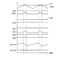
図9には、SBモードにおけるスイッチング素子の制御動作例を説明するための波形図が示される。SBモードでは、電圧指令値VH*に対する出力電圧VHの電圧偏差ΔVH(ΔVH=VH*−VH)を補償するように、(3)式のデューティ比Dcが演算される。そして、キャリア波CWとデューティ比Dcとの電圧比較に基づいて、制御パルス信号SDcが生成される。制御パルス信号/SDcは、制御パルス信号SDcの反転信号である。SBモードでは、直流電圧(Va+Vb)と、出力電圧VHとの間のDC/DC変換が図8に示された昇圧チョッパ回路によって実行される。
図10に示すように、制御信号SG3は、上述したようにスイッチング素子S3をオン固定するためにHレベルに固定される。これに対し、制御信号SG1,SG2,SG4は、制御パルス信号SDc(/SDc)の論理和に基づいて設定することができる。制御パルス信号SDcは、昇圧チョッパ回路の下アーム素子を構成するスイッチング素子S2,S4のペアの制御信号SG2,SG4とされる。同様に、昇圧チョッパ回路の上アーム素子を構成するスイッチング素子S1の制御信号SG1は、制御パルス信号/SDcによって得られる。その結果、下アーム素子を構成するスイッチング素子S2,S4のペアがオンされる期間と、上アーム素子を構成するスイッチング素子S1がオンされる期間とが反転関係で設けられる。
SBモードでは、直流電源10a,10bが直列接続された状態で、電力線20との間で双方向のDC/DC変換が実行される。したがって、直流電源10aの出力電力Paおよび直流電源10bの出力電力Pbを直接制御することができない。すなわち、直流電源10a,10bの出力電力Pa,Pbの比は、電圧Va,Vbの比によって、下記(4)式に従って自動的に決まる。なお、直流電源10a,10bからの出力電力の和(Pa+Pb)が負荷30へ入出力されることは、PBモードと同様である。
Pa/Pb=Va/Vb (4)
(PBDモードの昇圧動作)
次に、図11及び図12を参照してPBD動作モードでの昇圧動作について詳細に説明する。図11には、PBDモードにおける直流電源10aに対するDC/DC変換(昇圧動作)と、電力線20に対して直流電源10aと並列に直流電源10bが直結接続される様子が示される。
PBDモードでは、図11(a),(b)に示すように、スイッチング素子S1およびS4の各々がオン状態に固定される。これにより、直流電源10bが電力線20に直結接続される。その結果、直流電源10bからリアクトルL2、ダイオードD1およびスイッチング素子S1、電力線20、負荷30、接地配線21、ならびに、ダイオードD4およびスイッチング素子S4を電流が流れて直流電源10bに戻る電流経路87が形成される。
電流経路87ではダイオードD1,D4を通って電流が流れることができる。そのため、PBDモードでは、スイッチング素子S1,S4をオン固定しなくても、直流電源10bが電力線20に直結接続されて電流経路87が形成される。したがって、直流電源10bの出力動作だけを見れば、スイッチング素子S1,S4は、下記する直流電源10aの昇圧動作時に他のスイッチング素子S2,S3と同様にオンオフ制御されもよい。ただし、スイッチング素子S1,S4がオフされているとき、負荷30からの回生電力を直流電源10bに充電する電流経路が形成されないことになる。そのため、本実施形態ではスイッチング素子S1,S4をオン固定して、直流電源10bに対する回生電力の充電経路を確保している。
このようにPBDモードでは、直流電源10bが電力線20に直結接続されるため、直流電源10bの電圧VbがDC/DC変換(直流電圧変換)されずに電力線20に出力される。これにより、電力線20の出力電圧VHは直流電源10bの電圧Vbとほぼ等しくなる。そのため、電力線20の出力電圧VHを制御することができない。したがって、PBDモードは、負荷30の要求電力に応じて決まる電力線20の出力電圧VHの電圧指令値VH*が直流電源10bの電圧Vb以下の場合に適用することができる動作モードである。なお、直流電源10aの電圧Vaが直流電源10bの電圧Vbよりも大きい場合(Va>Vb)には、直流電源10aを電力線20に対して直結接続する一方、直流電源10bに対して昇圧動作を行うことで、PBDモードを実行してもよい。
一方、直流電源10aと電力線20との間では、図4〜図6を参照して上述したPBモードとほぼ同様の昇圧動作が実行される。図11(a)に示すように、スイッチング素子S3をオンし、スイッチング素子S2をオフすることによって、リアクトルL1にエネルギーを蓄積するための電流経路88が形成される。これにより、昇圧チョッパ回路の下アーム素子がオンした状態が形成される。
これに対し、図11(b)に示すように、スイッチング素子S3をオフするとともに、スイッチング素子S2をオンすることによって、リアクトルL1の蓄積エネルギーを直流電源10aのエネルギーとともに出力するための電流経路89が形成される。これにより、昇圧チョッパ回路の上アーム素子がオンした状態が形成される。
上記のようにスイッチング素子S3がオンされる一方で、スイッチング素子S2がオフされている第1の期間と、スイッチング素子S2がオンされる一方でスイッチング素子S3がオフされている第2の期間とを交互に繰り返すことにより、直流電源10aに対する昇圧チョッパ回路が構成される。
ここで、図11に示されるDC/DC変換動作は、昇圧後の電圧が直流電源10bの電圧Vb(すなわち電力線20の出力電圧VH)と等しいとみなせる電圧範囲内に制御される。ここで「等しいとみなせる電圧範囲」とは、昇圧後の電圧が直流電源10bの電圧Vbより若干高い場合と若干低い場合も含む意である。直流電源10aの昇圧後の電圧を直流電源10bの電圧Vbより若干高く設定することで、直流電源10bから流れる電流Ibが減るものの直流電源10aから流れる電流Iaが増えることで、電力線20に流れる総電流(Ia+Ib)は増加する。その結果、負荷30に供給される総電力PHが増加することになる。
反対に、直流電源10aの昇圧後の電圧を直流電源10bの電圧Vbより若干低く設定することで、直流電源10aから流れる電流Iaが直流電源10bからの電流増加量以上に減ることによって、電力線20に流れる総電流(Ia+Ib)は減少する。その結果、負荷30に供給される総電力PHが減少することになる。
PBDモードにおける直流電源10aに対する昇圧後の電圧は、昇圧チョッパ回路の下アーム素子を構成するスイッチング素子S3がオンされる期間のデューティ比Daを調整することによって制御できる。すなわち、スイッチング素子S3のデューティ比を調整することによって、直流電源10aから電力線20に供給される電力量を制御できるとともに、直流電源10a,10b間での電力分配比も所定範囲で制御することができる。ここで、PBDモードにおける直流電源10aの電圧Vaと電力線20の出力電圧VHとの間には、デューティ比Daを含む上記(1)式に示す関係が成立することはPBモードの場合と同様である。
図12には、PBDモードにおけるスイッチング素子の制御動作例を説明するための波形図が示される。図12を参照すると、本実施形態におけるPBDモードでは、直流電源10bの出力を出力電圧VHとするとともに、直流電源10aの出力を電流Iaの電流偏差を補償するように制御するように制御(電流制御)することができる。この際、電流制御の指令値(Ia*)は、直流電源10aの出力電力を制御するように設定することができる。この場合、デューティ比Ddは、電流偏差ΔIa(ΔIa=Ia*−Ia)に基づいて演算される。
直流電源10aの出力を制御するためのデューティ比Daと、キャリア波CWaとの電圧比較に基づいて、制御パルス信号SDaが生成される。制御パルス信号/SDaは、制御パルス信号SDaの反転信号である。これに対し、スイッチング素子S1,S4は、オン状態に維持されるため、上アーム素子に相当するスイッチング素子S1,S4のデューティ比Dbは零で一定に設定される。その結果、図13に示すように制御信号SG1,SG4の各々はHレベルに固定され、いわゆる「上アームオン」の状態となる。
図12および図13から理解されるように、PBDモードでは、制御信号SG2およびSG3が反転関係にあるため、スイッチング素子S2およびS3は反対にオンオフされる。また、制御信号SG1およびSG4はオン状態に維持される。これにより、直流電源10aについて、デューティ比Daに従った直流変換動作を実行できる。
PBDモードでは、負荷電力PLに対する、電流制御される直流電源10aからの出力電力の不足分が、直結接続される直流電源10bから出力されることになる。このため、電流制御での電流指令値の設定によって、直流電源10a,10b間での電力分配比を間接的に制御することが可能になる。その結果、PBDモードでは、直流電源10a,10b全体が電力線20に対して入出力する総電力PH(PH=Pa+Pb)のうち、直流電源10a,10bの電力分配を制御することができる。また、電流指令値の設定によって、一方の直流電源からの出力電力により他方の直流電源を充電する動作も可能になる。
(動作モードの選択処理)
次に、本実施形態における電力変換器制御における動作モードの選択処理について説明する。図14には、図3に示した各動作モードにおける直流電源10a,10b間での電力分配比kの制御可否、および、出力電圧VHの設定可能範囲が示される。
図14を参照すると、PBモードでは、電流制御対象となる直流電源での電流指令値の設定により、直流電源10a,10b間の電力分配比kを制御することができる。ここで、電力分配比kは、総電力PH(PH=Pa+Pb)に対する直流電源10aの出力電力Paの比で定義される(k=Pa/PH)。すなわち、PBモードでは、0〜1.0の範囲内で任意の値に、電力分配比kを設定することができる。なお、PBモードでは、出力電圧VHは、電圧VaおよびVbの最大値であるmax(Va,Vb)から、出力電圧VHの制御上限値である上限電圧VHmaxまでの範囲内で制御することができる。この場合、Va>Vbのときはmax(Va,Vb)=Vaであり、Vb>Vaのときはmax(Va,Vb)=Vbである。また、上限電圧VHmaxは、部品の耐圧等を考慮して定められる上限値である。
これに対し、PBDモードでも、電流制御対象となる直流電源10aでの電流指令値Ia*の設定により、直流電源10a,10b間の電力分配比kを制御することができる。ただし、PBDモードは、各直流電源10a,10bに対する各デューティ比を独立に制御可能なPBモードとは異なり、直流電源10aに対する昇圧後の電圧が電力線20に対する直流電源10bの出力電圧Vbとほぼ同等にするという制約がある。そのため、電力分配比kの設定範囲は、PBモードよりも狭い範囲に制限される。また、PBDモードでは、電力線20の出力電圧VHは、直結接続されている直流電源10bの電圧Vbに一意に決まる。
なお、他の動作モードのうち、一方の直流電源のみを使用するaBモード、bBモード、aDモードおよびbDモードでは電力分配比kは1または0である。また、SBモードおよびSDモードでは、各直流電源10a,10bの電圧Va,Vbの比によって電力分配比kが一意に決まるため、電力分配制御は行えない。さらに、PDモードでは、並列に直結接続された各直流電源10a,10bの内部抵抗Ra,Rbの比によって電力分配比kが一意に決まるため、この場合にも電力分配制御は行えない。
電源システム1において、負荷30へ供給される出力電圧VHは、負荷30の動作状態(例えば、トルクおよび回転数)に応じて設定される。図2に例示するように、負荷30が、電動車両に駆動力発生源として搭載されたモータジェネレータ35である場合、車速やアクセル開度等に基づいてモータジェネレータ35の負荷要求電圧VHrqが設定される。負荷30への供給電圧となる電力線20の出力電圧VHは、少なくとも負荷要求電圧VHrq以上に設定する必要がある。そのため、負荷30の動作状態に応じて設定された負荷要求電圧VHrqの範囲に依存して、電力変換器50における適用可能な動作モードが異なってくる。
図15には、負荷要求電圧VHrqの電圧範囲VR1〜VR3の定義が示される。図16は、各電圧範囲における動作モードの選択を説明するための図表である。
図15を参照すると、負荷要求電圧VHrqは、電圧範囲VR1(VHrq≦max(Va,Vb))、VR2(max(Va,Vb)<VHrq≦Va+Vb)およびVR3(Va+Vb<VHrq≦VHmax)のいずれかに設定される。
電力変換器50は、max(Va,Vb)よりも低い電圧を出力することができないため、負荷要求電圧VHrqが電圧範囲VR1内であるときには、出力電圧VHを負荷要求電圧VHrqに一致させることができない。したがって、図16に示すように、電圧範囲VR1では、VH≧VHrqの範囲でなるべくVHをVHrqに近づけるため、aDモード、bDモード、PDモードおよびPBDモードが、適用可能な動作モード群として選択される。
PBDモードを除く昇圧モードに属するaBモード、bDモードおよびPBモードでは、出力電圧VHは、max(Va,Vb)〜VHmaxの範囲内であれば、電圧指令値VH*に従って制御ことができる。一方、SBモードでは、出力電圧VHを(Va+Vb)より低く制御することができない。すなわち、出力電圧VHは、(Va+Vb)〜VHmaxの範囲内であれば、電圧指令値VH*に従って制御することができる。
電圧範囲VR2では、上述した各動作モードでの出力電圧VHの制御可能範囲に照らして、aBモード、bBモードおよびPBモードが、適用可能な動作モード群として選択される。これらの動作モードの適用時には、VH*=VHrqとすることにより、出力電圧VHを負荷要求電圧VHrqに一致させることが可能である。一方、aDモード、bDモード、PDモードおよびPBDモードは、電圧不足により適用することができない。
また、SDモードは、VH≧VHrqの条件を満たすため、電圧範囲VR2において適用可能である。SDモードでは、出力電圧VH(VH=Va+Vb)を負荷要求電圧VHrqに一致させることはできないが、スイッチングしないので電力変換器50での損失が大幅に抑制される。このため、電源システム1全体の損失については、aBモード、bBモードおよびPBモードの適用時よりも抑制できる可能性がある。したがって、SDモードについても、電圧範囲VR2で適用可能な動作モード群に含めることができる。逆に言うと、SBモードでは、出力電圧VHと負荷要求電圧VHrqとの差、および、電力変換器50での損失がSDモードよりも大きくなるため、電圧範囲VR2で適用可能な動作モード群からSBモードは除かれている。
電圧範囲VR3は、上述した動作モードでの出力電圧VHの制御可能範囲に照らして、PBモード、SBモード、aBモードおよびbBモードが、適用可能な動作モード群として選択される。これらの動作モードの適用時には、VH*=VHrqとすることにより、出力電圧VHと負荷要求電圧VHrqとを一致させることが可能である。一方で、各直結モード(aDモード、bDモード、PDモード、およびSDモード)ならびにPBDモードは、電圧不足により適用することができない。
図16を参照すると、各電圧範囲VR1,VR2,VR3には、複数の動作モードがそれぞれ含まれる。制御装置40では、このうちの1つの動作モードを選択して適用する。この際、制御装置40は、負荷30の動作状態に応じて求められた負荷要求電圧VHrqと、直流電源10a,10bの電源状態(例えば、SOCや充放電制限)とに基づいて、電源システム1全体の損失を最小とするための動作モードを1つ選択することができる。電源状態には、例えば、電圧Va,Vb、電流Ia,Ib、温度Ta,Tb等を含む。また、総電力PHおよび電力分配比kから、直流電源10a,10bの出力電力Pa,Pbを求めることができる。
制御装置40が電源システム1全体の損失を考慮して複数の動作モード群から1つの動作モードを選択する一例について具体的に説明する。まず、電源システム1の損失には、電力変換器50において発生するコンバータ損失Plcv、負荷30において発生する負荷損失Plld、直流電源10a,10bの内部抵抗Ra,Rbによって発生する電源損失Plpsなどが含まれる。
コンバータ損失Plcvには、スイッチング素子S1〜S4のオンオフ制御によるスイッチング損失と、リアクトルL1,L2の鉄損とが含まる。ただし、aDモード、bDモード、SDモードおよびPDモードの直結モードでは、スイッチング素子S1〜S4がオンまたはオフの状態に固定されることからスイッチング損失は発生しない。したがって、この場合、コンバータ損失Plcvは電力変換器50の通過電流に比例することになる。
コンバータ損失Plcvは、負荷要求電圧VHrq(または出力電圧VH)、ならびに、直流電源10a,10bの電圧Va,Vbおよび出力電力Pa,Pbの関数として、予め設定されたマップまたは演算式に従って、適用可能な動作モード毎に推定することができる。ここで、出力電力Pa,Pbは、総電力PH(PH=Pa+Pb)および電力分配比kから求めることができる。具体的には、Pa=PH×k、Pb=PH×(1−k)により算出できる。この際の電力分配比kは、例えば、直流電源10a,10bの状態(例えば、SOCのバランスおよび充放電制限のバランス)、あるいは、出力電力レベル(PH)等に基づいて、予め作成されたマップの参照等によって決めることができる。なお、上記のマップまたは演算式は、実験結果またはシミュレーション結果等に基づいて、予め求めることができる。このことは、以下においても同様である。
負荷損失Plldは、負荷要求電圧VHrq(または出力電圧VH)、トルク、回転数等を含む負荷30の動作状態の関数として予め設定されたマップまたは演算式に従って、適用可能な動作モード毎に推定することができる。
電源損失Plpsは、直流電源10a,10bの内部抵抗Ra,Rbと電圧Va,Vbおよび総電力PHの関数として、予め設定されたマップまたは演算式に従って、適用可能な動作モード毎に推定することができる。直流電源10a,10bの内部抵抗Ra,Rbは、直流電源10a,10bの状態(例えば、温度Ta,Tb、SOCa,SOCbなど)に応じて変化するから、現在の電源状態からマップまたは演算式に従って内部抵抗Ra,Rbを推定する。
制御装置40は、上記のようにして推定されたコンバータ損失Plcv、負荷損失Plldおよび電源損失Plpsの和を、適用可能な動作モード毎に算出して比較する。そして、制御装置40は、その和が最小となる1つの動作モードを複数の適用可能な動作モード群から選択する。このように選択された動作モードを適用して電力変換器50を制御することで、電源システム1全体の損失を最小にして効率向上を図ることができる。
(制御装置による電力変換器制御)
図17は、本実施形態の電源システムにおける電力変換器制御の基本的な概念を説明する図である。図17を参照すると、出力電圧VHは、総電力PHが負荷電力PLよりも大きい状態(PH>PL)では上昇する一方で、PH<PLの状態では低下する。したがって、本実施形態における電力変換器制御では、出力電圧VHの電圧指令値VH*に対する電圧偏差ΔVHに応じて総電力PHの指令値を設定する。また、総電力PHを出力電力PaおよびPbに分配することにより、各直流電源10a,10bの出力を電力制御(電流制御)する。
図18および図19は、本実施形態における電力変換器制御を説明するためのブロック図である。図18には、各直流電源の電力指令値を設定する制御演算のための構成が示されるとともに、図19には、設定された電力指令値に従って各直流電源の出力を制御する制御演算のための構成が示される。以下では、まずPBモードの制御構成について説明し、続いて他の昇圧モードの制御動作について説明する。
図18を参照すると、制御装置40は、パワー管理部100と、電力制御部200とを含む。
パワー管理部100は、直流電源10a,10bおよび/または負荷30の動作状態に基づいて、総電力PHに関する電力上限値PHmaxおよび電力下限値PHminと、直流電源10aの放電制限値Paoutおよび充電制限値Painと、直流電源10bの放電制限値Pboutおよび充電制限値Pbinと、直流電源10aおよび10bの間の電力分配比kとを設定する。ここで、総電力PHの電力上限値PHmaxは直流電源10a,10bの放電制限値Paout,Pboutの和(PHmax=Paout+Pbout)として設定することができる。また、総電力PHの電力下限値Pminは、直流電源10a,10bの充電制限値Pain,Pbinの和(PHmin=Pain+Pbin)として設定することができる。
また、パワー管理部100は、電力分配比kを設定することができる。上述したように、PBモードでは、0≦k≦1.0の任意の値に電力分配比kを設定でき、PBDモードではこれよりも狭い所定の範囲で電力分配比kを設定することができる。
さらに、パワー管理部100は、直流電源10a,10bの間で充放電を行うための循環電力値Prを設定することができる。循環電力値Prは、直流電源10bを充電するための直流電源10aからの出力電力に相当する。例えば、力行動作時には、k=1とした上でPr>0に設定すると、直流電源10aの出力電力によって、総電力PHを電力線20に対して供給しつつ、直流電源10bを充電することができる。反対に、k=0とした上でPr<0に設定すると、直流電源10bの出力によって、総電力PHを電力線20に対して供給しつつ、直流電源10aを充電することができる。
また、回生動作時(PH<0)には、k=0とした上でPr>0に設定すると、負荷30からの回生電力と、直流電源10aからの出力電力の両方によって、直流電源10bを充電することができる。反対に、k=1とした上でPr<0に設定すると、負荷30からの回生電力と、直流電源10bからの出力電力との両方によって、直流電源10aを充電することができる。
これに対し、循環電力値Prが設定されないとき(Pr=0)、直流電源10a,10bの間で充放電はされない。パワー管理部100は、例えば、直流電源10a,10bのSOCが不均衡である場合に、低SOC側の直流電源の充電を促進するように循環電力値Prを設定することができる。
電力制御部200は、出力電圧VHの電圧偏差に基づいて、直流電源10a,10bの電力指令値Pa*,Pb*を設定する。電力制御部200は、偏差演算部210と、制御演算部220と、第1のリミッタ230と、電力分配部240と、循環電力加算部250と、第2のリミッタ260と、減算部270とを有する。
偏差演算部210は、電圧指令値VH*および出力電圧VHの検出値の差である電圧偏差ΔVH(ΔVH=VH*−VH)を算出する。制御演算部220は、電圧偏差ΔVHに基づいて、電圧制御のために要求される総電力PHrを算出する。例えば、制御演算部220は、PI演算によって下記の(5)式に従ってPHrを設定する。
PHr=Kp・ΔVH+Σ(Ki・ΔVH) (5)
式(5)中のKpは比例制御ゲインであり、Kiは積分制御ゲインである。これらの制御ゲインには、平滑コンデンサCHの容量値も反映される。式(5)に従って総電力PHrを設定することにより、電圧偏差ΔVHを低減するためのフィードバック制御を実現できる。
第1のリミッタ230は、パワー管理部100によって設定されたPHmax〜PHminの範囲内となるように、電力指令値PH*を制限する。もし、PHr>PHmaxのときは、第1のリミッタ230によって、PH*=PHmaxに設定される。同様に、PHr<PHminのときには、第1のリミッタ230は、PH*=PHminに設定する。また、PHmax≧PHr≧PHminのときには、そのままPH*=PHrに設定される。これにより、総電力指令値PH*が確定する。
電力分配部240は、総電力指令値PH*および電力分配比kに基づいて、直流電源10aが分担すべき出力電力k・PH*を算出する。循環電力加算部250は、電力分配部240によって算出されたk・PH*と、パワー管理部100によって設定された循環電力値Prとを加算することによって、直流電源10aが要求される電力Parを算出する(Par=k・PH*+Pr)。
第2のリミッタ260は、パワー管理部100によって設定されたPaout〜Painの範囲内となるように、直流電源10aの電力指令値Pa*を制限する。もし、Par>Paoutのときには、第2のリミッタ260によりPa*=Paoutに修正される。同様に、Par<Painのときには、第2のリミッタ260は、Pa*=Painに修正する。また、Pamax≧Par≧Painのときには、そのままPa*=Parとされる。これにより、直流電源10aの電力指令値Pa*が確定する。
減算部270は、総電力指令値PH*から電力指令値Pa*を減算することによって、直流電源10bの電力指令値Pb*を設定する(Pb*=PH*−Pa*)。
図19に示すように、制御装置40は、電力指令値Pa*,Pb*に従って直流電源10a,10bからの出力を制御するための、電流制御部300,310、PWM制御部400およびキャリア波発生部410を含む。電流制御部300は、電流制御によって直流電源10aの出力を制御する。電流制御部310は、電流制御によって直流電源10bの出力を制御する。
電流制御部300は、電流指令生成部302と、偏差演算部304と、制御演算部306と、FF加算部308とを有する。
電流指令生成部302は、電力指令値Pa*と、電圧Vaの検出値とに基づいて、直流電源10aの電流指令値Ia*を設定する(Ia*=Pa*/Va)。偏差演算部304は、電流指令値Ia*および電流Iaの検出値の差である電流偏差ΔIa(ΔIa=Ia*−Ia)を算出する。制御演算部306は、電流偏差ΔIaに基づいて、電流フィードバック制御の制御量Dfbaを算出する。例えば、制御演算部306は、PI演算によって、下記(6)式によりDfbaを算出する。
Dfba=Kp・ΔIa+Σ(Ki・ΔIa) (6)
式(6)中のKpは比例制御ゲインであり、Kiは積分制御ゲインである。これらの制御ゲインは、上記の式(5)とは別個に設定される。
一方で、電圧フィードフォワード制御のFF制御量Dffaは、式(1)をDaについて解くことで得られるDa=(VH−Va)/VHに沿って、式(7)により設定される。
Dffa=(VH*−Va)/VH* (7)
FF加算部308は、FB制御量DfbaおよびFF制御量Dffaを加算することによって、直流電源10aの出力制御に関するデューティ比Daを算出する。デューティ比Daは、式(1)と同様に、直流電源10aの電圧Vaと出力電圧VHとの間でDC/DC変換を行う際の、昇圧チョッパ回路(図4)の下アーム素子(スイッチング素子S3,S4)がオンされる期間のデューティ比に相当する。
電流制御部310は、電流指令生成部312と、偏差演算部314と、制御演算部316と、FF加算部318とを有する。
電流指令生成部312は、電力指令値Pb*と、電圧Vbの検出値とに基づいて、直流電源10bの電流指令値Ib*を設定する(Ib*=Pb*/Vb)。偏差演算部314は、電流指令値Ib*および電流Ibの検出値の差である電流偏差ΔIb(ΔIb=Ib*−Ib)を算出する。制御演算部316は、電流偏差ΔIbに基づいて、電流フィードバック制御の制御量Dfbbを算出する。例えば、制御演算部316は、PI演算によって、下記(8)式によりDfbbを算出する。
Dfbb=Kp・ΔIb+Σ(Ki・ΔIb) (8)
式(8)中のKpは比例制御ゲインであり、Kiは積分制御ゲインである。これらの制御ゲインは、上記の式(5)および(6)とは別個に設定される。
一方で、電圧フィードフォワード制御のFF制御量Dffbは、式(2)をDbについて解くことで得られるDb=(VH−Vb)/VHに沿って、式(9)により設定される。
Dffb=(VH*−Vb)/VH* (9)
FF加算部318は、FB制御量DfbbおよびFF制御量Dffbを加算することによって、直流電源10bの出力制御に関するデューティ比Dbを算出する。デューティ比Dbは、式(2)と同様に、直流電源10bの電圧Vbと出力電圧VHとの間でDC/DC変換を行う際の、昇圧チョッパ回路(図5)の下アーム素子(スイッチング素子S2,S3)がオンされる期間のデューティ比に相当する。
PWM制御部400は、電流制御部300,310によって設定されたデューティ比Da,Db、ならびに、キャリア波発生部410からのキャリア波CWa,CWbに基づくパルス幅変調制御によって、スイッチング素子S1〜S4の制御信号SG1〜SG4を生成する。PWM制御部400によるパルス幅変調制御および制御信号SG1〜SG4の生成は、図6および図7で説明したのと同様に実行されるので、詳細な説明は繰り返さない。
このように、本実施形態における電力変換制御によれば、PBモードでのDC/DC変換において、出力電圧VHの電圧偏差を電力指令値に変換して、各直流電源10a,10bの出力を電流制御することによって、出力電圧VHを電圧指令値VH*に制御することができる。これにより、各直流電源10a,10bを、出力電力ベースで確実に過電力(すなわち過放電および過充電)から保護することが可能になる。また、直流電源10a,10b間での電力分配比kや循環電力値Prを簡易に制御することができる。
特に、PBモードの場合、直流電源10a,10bの一方に対しては、電力指令値を直接制限することができる。図17の構成例では、第2のリミッタ260により、直流電源10aの電力指令値Pa*をPain≦Pa*≦Paoutの範囲内に確実に制限することができる。これにより、直流電源10aの過電力を厳密に防止できる。
次に、PBモード以外の昇圧モード、すなわち、aBモード、bBモード、SBモード、および、PBDモードの電圧変換器制御について説明する。
まず、aBモードにおいても、PBモードと同様に、偏差演算部210、制御演算部220および第1のリミッタ230によって総電力指令値PH*が設定される。この場合、直流電源10bは不使用とされるので、第1のリミッタ230に与えられる電力上限値PHmaxおよび電力下限値PHminは、直流電源10aの放電制限値Paoutおよび充電制限値Painと同等に設定することができる。
aBモードでは、直流電源10aのみが出力電力を供給するため電力分配比k=1に設定される。また、直流電源10bは非使用(充放電回避)とされるので、循環電力値Pr=0に固定される。なお、第2のリミッタ260によってもPa*(=PH*)が放電制限値Paoutおよび充電制限値Painに制限されるので、この場合の第1および第2のリミッタのうち一方を非作動とすることもできる。
さらに、図19の構成において、電流フィードバック制御は、直流電源10aに対してのみ実行される。すなわち、電流制御部300は、PBモードと同様に作動してデューティ比Daを生成する。これに対し、aBモードでは、直流電源10bに対する昇圧動作は不要であるため、電流制御部310の動作は停止することができる。すなわち、デューティ比Dbの演算は行わない。
続いて、bBモードの制御について説明する。bBモードでは、上述したaBモードの制御と反対の制御が実行される。すなわち、bBモードでは、直流電源10aは不使用とされるので、第1のリミッタ230に与えられる電力上限値PHmaxおよび電力下限値PHminは、直流電源10bの放電制限値Pboutおよび充電制限値Pbinと同等に設定することができる。これにより、総電力指令値PH*(=Pb*)は、Pbin≦PH*≦Pboutに制限される。
bBモードでは、直流電源10bのみが出力電力を供給するため電力分配比k=0に設定される。また、直流電源10aは非使用(充放電回避)とされるので、循環電力値Pr=0に固定される。さらに、図19の構成において、電流フィードバック制御は、直流電源10bに対してのみ実行される。すなわち、電流制御部310は、PBモードと同様に作動してデューティ比Dbを生成する。これに対し、bBモードでは、直流電源10aに対する昇圧動作は不要であるため、電流制御部300の動作は停止することができる。すなわち、デューティ比Daの演算は行わない。
続いて、SBモードの制御について説明する。SBモードは、上述したように、直流電源10a,10bが直列接続された状態で、電力線20との間で双方向のDC/DC変換が実行される。したがって、直流電源10a,10bを流れる電流は共通になる(Ia=Ib)。このため、直流電源10aの出力電力Paおよび直流電源10bの出力電力Pbを直接制御することができず、各出力電力Pa,Pbの比は電圧Va,Vbの比によって上記(4)式に従って自動的に決まる(Pa/Pb=Va/Vb)。
また、SBモードでは、電力分配比kは、式(4)に沿って求められる下記の式(10)に従って、直流電源10a,10bの電圧Va,Vbの検出値に基づいて設定される。
k=Va/(Va+Vb) (10)
さらに、SBモードでは、直流電源10a,10b間での充放電はできないので、循環電力値Pr=0に設定される。
これらにより、図18の構成において、PBモードの同様に、出力電圧VHの電圧偏差ΔVHに基づいて総電力指令値PH*が設定され、第1のリミッタ230によって総電力指令値PH*がPHmax〜PHminの範囲内に設定される。さらに、式(10)により算出される電力分配比に従って、総電力指令値PH*が電力指令値Pa*およびPb*に分配される(Pa*=k・PH*、Pb*=PH*−Pa*)。
SBモードでは、Ia=Ibのため電流フィードバック制御は、直流電源10a,10bの一方のみで実行される。例えば、第2のリミッタ260によって電力指令値Pa*を直接制限することができる直流電源10aに対して電流制御部300により電力フィードバック制御が実行される。
これに対し、電流制御部310では、制御演算部316における制御ゲイン、具体的には上記式(8)中のKp,Kiを零にすることによって、電流フィードバック制御が非実行とされる。したがって、電流制御部310では、電圧Vbに基づくフィードフォワード制御のみによって、デューティ比Dbを算出する(Db=Dffb)。
次に、PBDモードの制御について説明する。PBDモードにおいても、PBモードの場合と同様に、電圧指令値VH*および出力電圧VHに基づいて、偏差演算部210、制御演算部220および第1のリミッタ230によって、電力指令値PH*が生成される。
ただし、PBDモードの場合、直流電源10bが電力線20に直結接続されていることから、電力指令値PH*を任意の電力分配比k(0≦k≦1)で電力分配することはできない。すなわち、電力線20の出力電圧VHが直流電源10bの電圧Vaに等しいとみなせる電圧範囲でしか制御できないため、直流電源10bから供給される出力電力もまたPb(すなわちPb*)=Ib・Vaでほぼ一定となる。
したがって、PBDモードを適用する際、制御装置40のパワー管理部100は電力分配部240に対し、PBモードのような任意の電力分配比kではなく、電力指令値PH*から直流電源10bの出力可能な電力指令値Pb*を減算した電力値を直流電源10aの電力指令値Pa*とするように、電力分配比kを与えることになる。このように制約から、PBDモードにおける電力分配比kは、PBモードに比べて狭い範囲に限定されることは上述したとおりである。
なお、PBDモードにおいても、第1のリミッタ230によってPHmin≦電力指令値PH*≦PHmaxに制限されること、循環電力加算部250によって循環電力Prが電力指令値PH*に加算されること、および、第2のリミッタ260によってPain≦Pa*≦Paoutに制限されることは、PBモードの場合と同様である。
上記のようにして生成された各直流電源10a,10bの電力指令値Pa*,Pb*は、図19に示す制御構成に与えられる。
電流制御部300では、電力指令値Pa*に応じた出力電力Paを直流電源10aから出力するようにPBモードの場合と同様に電流フィードバック制御が実行される。一方、直流電源10bについては、電力変換器50のスイッチング素子S1,S4がオン固定されて電力線20に直結接続された状態に維持される。そのため、図19中の電流制御部310の作動は停止され、直流電源10bのDC/DC変換は実行されない。
このように、本実施形態における電力変換器制御によれば、図1に示した電力変換器50の制御動作について、出力電圧VHを電圧指令値VH*に制御する昇圧モードに属する各動作モード間で、図18および図19に示した制御構成を共通化できる。したがって、複数の動作モードを選択的に適用する電力変換器50の制御における制御演算負荷を軽減することができる。また、動作モードの切り替えが円滑に行えるので、制御性を向上することができる。
(PBDモードにおける電力制限処理)
次に、図20ないし図24を参照して、PBDモードにおける電力制限処理について説明する。
図20は、PBDモードにおける直流電源10a,10b間での電力分配例を示す図である。図20(a)は、PBDモードにおいて直流電源10aから出力される電力だけが示され、(b)は直流電源10a,10bからそれぞれ出力される電力Pa,Pbの和として総電力指令値PH*が示される。
図20(a)を参照すると、PBDモードにおいて直流電源10aから出力される電力Paは、図18を参照して上述した電力制御部200によって生成された電力指令値Pa*に従って、図19の電流制御部300により制御される。また、電力指令値Pa*は、電力制御部200の第2のリミッタ260によって、直流電源10aの放電制限値Paout以下に制限される。これにより、直流電源10aにおいて過放電が生じないように制御されている。
しかし、電力変換器50の応答性の遅れが生じることがある。この場合には、直流電源10aの電力指令値Pa*に対して、電力変換器50から電力線20に実際に供給される電力Paが不足することが生じ得る。このような電力不足分は生じている間、電力線20に直結接続されている直流電源10bから引き出されてしまうことによって、直流電源10bから出力される電力が直流電源10bの放電制限値Pboutを一時的に超えることが発生する。その結果、直流電源10bの劣化を進行させることになる。
そこで、本実施形態では、PBDモードが適用されている場合に、直結接続される側の直流電源10bにおいて過放電が生じるのを適切に抑制するために、下記のような電力制限処理を実行する。
図21は、制御装置40に含まれるパワー管理部100において上記電力制限処理に関わる部分を示す機能ブロック図である。パワー管理部100は、動作モード判定部102と、電力制限切替部104と、電力指令異常処理部106とを含む。
動作モード判定部102は、図3に示される複数の動作モード群からPBDモードが選択されたか否かを判定する機能を有する。PBDモードが選択されているか否かは、スイッチング素子S1〜S4の動作状態、出力電圧VHの電圧値等によって判定できる。具体的には、例えば、電力線20の出力電圧VHが電圧範囲VR1(図15)に属し、スイッチング素子S1,S4の制御信号SG1がHレベルに固定された状態でスイッチング素子S2,S3の制御信号SG2,SG3がデューティ比Daに従って制御されているとき、PBDモードが選択されていると判定できる。
電力制限切替部104は、PBDモードが適用されているとき、総電力PHの電力指令値PH*に対する制限値を切り替える機能を有する。より詳しくは、図18に示す構成において第1のリミッタ230により総電力指令値PH*はPH*≦PHmax(PHmax=Paout+Pbout)に制限され、第2のリミッタ260によって直流電源10aの電力指令値Pa*≦放電制限値Paoutに制限される。ここで、PBDモード以外の動作モードではPHmax=Paout+Pboutに設定されている。これに対し、PBDモードが選択された場合、電力制限切替部104は、直流電源10aの実電力Paactと直流電源10bの放電制限値Pboutとの和を総電力PHの最大値PHmaxとして設定するように切り替える。ここで、直流電源10aの実電力Paactは、直流電源10aについて検出される電流Iaおよび電圧Vaの積として算出したものを用いることができる(Paact=Ia・Va)。本実施形態では、電流Iaに代えて、電流センサ12aにより検出されるリアクトル電流ILaを用いて実電力Paactを算出することができる。
電力指令異常処理部106は、電源システム1のハード構成の性能ばらつきや、電力制御に関連するデータを検出する電圧センサ、電流センサおよび温度センサ等のセンサ誤差を考慮して設定された上限値および下限値を設定し、これらの上下限値を総電力PHが超えた場合にセンサ異常として電力指令値PH*を修正する機能を有する。
上記直流電源10a,10bのハード構成の性能ばらつきとしては、例えば、同じ直流電源10a(または10b)として組み立てられた電源装置の個体間における充放電特性のばらつき等を上げることができる。また、センサ誤差は、電流センサ等に用いるセンサに固有の値として予め規定された誤差値(または公差)を用いることができる。
図22は、図21の構成を有するパワー管理部100において実行される電力制御処理の手順を示すフローチャートである。この電力制御処理は、制御装置40の記憶部に予め記憶されたソフトウェアまたはプログラムを所定時間ごとに実行することができる。
まず、パワー管理部100は、ステップS10により、電力変換器50の動作モードとしてPBDモードが選択されているか否かを判定する。この処理は、図21に示す動作モード判定部102の機能として実行される。ここで肯定判定されるとステップS12に進み、否定判定されるとステップS14に進む。
パワー管理部100は、ステップ10において動作モードとしてPBDモードが選択されていると判定したとき(ステップS10でYES)、続くステップS12により、電力線20に供給される総電力PHの電力指令値PH*の最大値であるPHmaxを、直流電源10aの実電力Paactと直流電源10bの放電制限値Pboutとの和に設定する(PHmax=Paact+Pbout)。この処理は、図21の電力制限切替部104の機能として実行される。
一方、ステップS10において否定判定されたとき(ステップS10でNO)、パワー管理部100は、続くステップS14により、電力線20に供給される総電力PHの電力指令値PH*の最大値であるPHmaxを、直流電源10a,10bの放電制限値Paout,Pboutの和に設定(または維持)する(PHmax=Paout+Pbout)。この処理は、図21の電力制限切替部104の機能として実行される。
図24を参照して上記ステップS12の処理を詳しく説明すると、総電力PHの最大値PHmaxが直流電源10aの実電力Paactと直流電源10bの放電制限値Pboutとの和に設定されることで、総電力PHの電力指令値PH*に電力変換器50の応答性の遅れによって生じた電力指令値Pa*と実電力Paactとの差、すなわち電力不足分が電力指令値Pa*から差し引かれたものになる。これにより、直流電源10a,10bの総電力PHの電力指令値PH*が電力不足分だけ減少した値PH*mdyに修正される。その結果、電力線20に直結接続された直流電源10bから上記電力不足分に相当する電力が引き出されるのを回避でき、直流電源10の出力電力Pbが放電制限値Pboutを超えないようにすることができる。したがって、出力電力Pbが放電制限Pboutを超えることによる直流電源10bの劣化進行を抑制することができる。
なお、上記のように総電力PHの最大値PHmaxを制限することにより、電力変換器50の応答性が電力指令値Paに応じた電力を出力できる程度に回復するまでの間、負荷30の動作状態(たとえば、トルク等)が必要に応じて一時的に制限される。電源システム1が車両に搭載される場合には、上記のようなトルクの制限によるドライバビリティの悪化を抑制するように、トルク変化を時間的に緩慢にする処理等を施すのが好ましい。
図22を再び参照して、パワー管理部100は、ステップS12の処理を実行した後に、ステップS16により、総電力PHの電力指令値PH*が上限値または下限値を超えているか否かを判定する。そして、続くステップS18により、電力指令値PH*が上限値を上回っている場合にはPH*を上限値に設定し、一方、電力指令値PH*が下限値を下回っている場合にはPH*を下限値に設定する処理を実行する。これらの処理は、図21の電力指令異常処理部106の機能として実行される。
上記ステップS16,S18の処理を詳しく説明する。図23は、図21に示す電力指令異常処理部106の機能を模式的に説明するための図である。図23には、横軸に時間tが取られ、縦軸に総電力PHの電力指令値PH*が取られたグラフにおいて、電力指令値PH*の上側に上限値PHthupが設定され、電力指令値PH*の下側に下限値PHthlwが設定される例が示されている。
電力指令値PH*の上限値PHthupおよび下限値PHthlwは、電源システム1のハード構成による性能ばらつき、電力制御に関連するデータを取得する電圧センサや電流センサ等の誤差(または公差)、および、電力変換器50の応答性(時定数)を考慮して設定される。具体的には、電力指令値PH*に関するゲインGL,Gh(ここで0<GL≦1.0≦GH)、オフセットOL,OH(ここでOL≦0.0≦OH)、および、応答性(時定数)TL,TH(ここで0<TL≦(中央値)≦TH)とすると、下記の(11),(12)式によって算出することができる。
上限値PHthup=[PH*×GH+OH]の時定数THによるなまし (11)
下限値PHthlw=[PH*×GL−OL]の時定数TLによるなまし (12)
上記のゲインGL,Gh、オフセットOL,OH、応答性(時定数)TL,THは、電源システム1が異常なく動作することを前提して設計により又は統計的に求めることができる。
図22のステップS16では、上記(11),(12)式によって算出された上限値PHthupおよび下限値PHthlwと総電力PHの電力指令値PH*が比較される。そして、図23中の白丸印90で示すように、電力指令値PH*が下限値PHthlwを下回っている場合にはステップS18により黒丸印91で示す下限値に修正する(PH*=PHthlw)。あるいは、図23中の白三角印92で示すように、電力指令値PH*が上限値PHthupを上回っている場合にはステップS18により黒三角印93で示す下限値に修正する(PH*=PHthup)。
このように電力指令値PH*を修正することで、例えばセンサの異常等によって電力指令値PH*も異常な値となった場合にも、負荷30の動作状態が急変するのを回避することがきる。したがって、電源システム1が車載されている場合に、センサ異常等による急減速や急加速等を回避して、適切な措置(例えばフェールセーフモード)を取ることができる。
図22を再び参照して、ステップS18の処理が実行された後、または、上記ステップS16において否定判定されたとき(すなわちPHthlw≦PH*≦PHthup)、電力制限処理を終了する。
上述したように、本実施形態の電源システム1によれば、PBDモードが選択されたときに総電力PHの電力指令値PH*の最大値PHmaxを直流電源10aの実電力Paactと直流電源10bの放電制限値Pboutとの和に設定することにより、電力線20に直結接続された直流電源10bの過放電を適切に抑制することができ、その結果、直流電源10bの劣化進行を低減できる。
また、本実施形態によれば、PBDモード以外の動作モードが選択されているとき、総電力PHの電力指令値PH*の最大値PHmaxは直流電源10a,10bの放電制限値Paout,Pboutの和に設定または維持される。これにより、直流電源10a,10bによって供給可能な電力を制約された範囲内で最大限にすることができる。その結果、例えば、電源システム1がハイブリッド自動車に搭載された場合に、エンジンのクランク時に必要な電力を適切に出力することができ、ハイブリッド自動車のエンジン始動性を向上させることができる。
さらに、本実施形態によれば、電源システム1のハード構成の性能ばらつきやセンサ誤差等を考慮した上限値PHthupおよび下限値PHthlwを総電力PHの電力指令値PH*に設けることとした。これにより、センサ異常等に起因した電源システム1の動作状態の急変を確実に防止することができる。
なお、本発明は、上述した実施形態およびその変形例の構成に限定されるものではなく、本願の特許請求の範囲に記載された事項およびその均等な範囲内において種々の変更や改良が可能である。
例えば、上記の電源システム1では、スイッチング素子S1〜S4のオンオフ状態を制御することによって2つの直流電源10a,10bを電力線20に対して直列または並列に接続切替可能な構成について説明したが、これに限定されるものではない。図25に示すように、直流電源10a,10bの各々に、独立して制御可能な電力変換器50a,50bが設けられており、電力線20に対して直流電源10a,10bが電力変換器50a,50bを介して並列接続されている電源システム1Aに適用されてもよい。
図25に示すように、直流電源10用の電力変換器50aは、直流電源10aの正極端子に一端が接続されたリアクトルL1と、リアクトルL1の他端に接続されたノードN5と電力線20との間に接続された上アーム素子としてのスイッチング素子S5と、ノードN5と接地配線21との間に接続された下アーム素子としてのスイッチング素子S6とを備える。そして、各スイッチング素子S5,S6には、ダイオードD5,D6が逆並列に接続されている。
一方、直流電源10b用の電力変換器50bは、直流電源10bの正極端子に一端が接続されたリアクトルL2と、リアクトルL2の他端に接続されたノードN7と電力線22との間に接続された上アーム素子としてのスイッチング素子S7と、ノードN7と接地配線23との間に接続された下アーム素子としてのスイッチング素子S8とを備える。そして、各スイッチング素子S7,S8には、ダイオードD7,D8が逆並列に接続され、電力線22が直流電源10a側の電力線20に、接地配線23が直流電源10a側の接地配線21にそれぞれ接続されている。なお、電源システム1Aの他の構成は上記実施形態と同様である。
図25に示す電源システム1Aでは、直流電源10aおよび10bを直列接続状態に切り換えることはできない。したがって、上記実施形態における図3に示す各動作モードのうちSBモードおよびSDモードを実行することはできないが、それ以外の動作モードは適用可能であり、上記実施形態と同様に電力変換器制御を実行することができる。具体的には、電力変換器50bに含まれるスイッチング素子S7をオン固定する一方、電力変換器10aにおいてDC/DC変換することにより、PBDモードを実行することができる。
なお、電源システム1Aにおいて電力変換器50bを省略して直流電源10bを電力線20および接地配線21に直結接続してもよい。この場合にも、上述した電源システム1と同様のPBDモードを実行することができる。