JP5639431B2 - Deposition equipment - Google Patents

Deposition equipment Download PDF

Info

Publication number
JP5639431B2
JP5639431B2 JP2010220263A JP2010220263A JP5639431B2 JP 5639431 B2 JP5639431 B2 JP 5639431B2 JP 2010220263 A JP2010220263 A JP 2010220263A JP 2010220263 A JP2010220263 A JP 2010220263A JP 5639431 B2 JP5639431 B2 JP 5639431B2
Authority
JP
Japan
Prior art keywords
base portion
vacuum chamber
mask
alignment
fixed base
Prior art date
Legal status (The legal status is an assumption and is not a legal conclusion. Google has not performed a legal analysis and makes no representation as to the accuracy of the status listed.)
Active
Application number
JP2010220263A
Other languages
Japanese (ja)
Other versions
JP2012072478A5 (en
JP2012072478A (en
Inventor
三之 田島
三之 田島
内田 敬自
敬自 内田
孝史 澁谷
孝史 澁谷
悌二 ▲たか▼橋
悌二 ▲たか▼橋
正直 藤塚
正直 藤塚
Current Assignee (The listed assignees may be inaccurate. Google has not performed a legal analysis and makes no representation or warranty as to the accuracy of the list.)
Canon Tokki Corp
Original Assignee
Canon Tokki Corp
Priority date (The priority date is an assumption and is not a legal conclusion. Google has not performed a legal analysis and makes no representation as to the accuracy of the date listed.)
Filing date
Publication date
Application filed by Canon Tokki Corp filed Critical Canon Tokki Corp
Priority to JP2010220263A priority Critical patent/JP5639431B2/en
Priority to CN201180046526.8A priority patent/CN103154304B/en
Priority to PCT/JP2011/070119 priority patent/WO2012043150A1/en
Priority to KR1020137006250A priority patent/KR101846982B1/en
Priority to TW100134788A priority patent/TWI585222B/en
Publication of JP2012072478A publication Critical patent/JP2012072478A/en
Publication of JP2012072478A5 publication Critical patent/JP2012072478A5/ja
Application granted granted Critical
Publication of JP5639431B2 publication Critical patent/JP5639431B2/en
Active legal-status Critical Current
Anticipated expiration legal-status Critical

Links

Images

Classifications

    • HELECTRICITY
    • H10SEMICONDUCTOR DEVICES; ELECTRIC SOLID-STATE DEVICES NOT OTHERWISE PROVIDED FOR
    • H10KORGANIC ELECTRIC SOLID-STATE DEVICES
    • H10K71/00Manufacture or treatment specially adapted for the organic devices covered by this subclass
    • H10K71/10Deposition of organic active material
    • H10K71/16Deposition of organic active material using physical vapour deposition [PVD], e.g. vacuum deposition or sputtering
    • CCHEMISTRY; METALLURGY
    • C23COATING METALLIC MATERIAL; COATING MATERIAL WITH METALLIC MATERIAL; CHEMICAL SURFACE TREATMENT; DIFFUSION TREATMENT OF METALLIC MATERIAL; COATING BY VACUUM EVAPORATION, BY SPUTTERING, BY ION IMPLANTATION OR BY CHEMICAL VAPOUR DEPOSITION, IN GENERAL; INHIBITING CORROSION OF METALLIC MATERIAL OR INCRUSTATION IN GENERAL
    • C23CCOATING METALLIC MATERIAL; COATING MATERIAL WITH METALLIC MATERIAL; SURFACE TREATMENT OF METALLIC MATERIAL BY DIFFUSION INTO THE SURFACE, BY CHEMICAL CONVERSION OR SUBSTITUTION; COATING BY VACUUM EVAPORATION, BY SPUTTERING, BY ION IMPLANTATION OR BY CHEMICAL VAPOUR DEPOSITION, IN GENERAL
    • C23C14/00Coating by vacuum evaporation, by sputtering or by ion implantation of the coating forming material
    • C23C14/04Coating on selected surface areas, e.g. using masks
    • C23C14/042Coating on selected surface areas, e.g. using masks using masks
    • CCHEMISTRY; METALLURGY
    • C23COATING METALLIC MATERIAL; COATING MATERIAL WITH METALLIC MATERIAL; CHEMICAL SURFACE TREATMENT; DIFFUSION TREATMENT OF METALLIC MATERIAL; COATING BY VACUUM EVAPORATION, BY SPUTTERING, BY ION IMPLANTATION OR BY CHEMICAL VAPOUR DEPOSITION, IN GENERAL; INHIBITING CORROSION OF METALLIC MATERIAL OR INCRUSTATION IN GENERAL
    • C23CCOATING METALLIC MATERIAL; COATING MATERIAL WITH METALLIC MATERIAL; SURFACE TREATMENT OF METALLIC MATERIAL BY DIFFUSION INTO THE SURFACE, BY CHEMICAL CONVERSION OR SUBSTITUTION; COATING BY VACUUM EVAPORATION, BY SPUTTERING, BY ION IMPLANTATION OR BY CHEMICAL VAPOUR DEPOSITION, IN GENERAL
    • C23C14/00Coating by vacuum evaporation, by sputtering or by ion implantation of the coating forming material
    • C23C14/22Coating by vacuum evaporation, by sputtering or by ion implantation of the coating forming material characterised by the process of coating
    • C23C14/24Vacuum evaporation
    • HELECTRICITY
    • H05ELECTRIC TECHNIQUES NOT OTHERWISE PROVIDED FOR
    • H05BELECTRIC HEATING; ELECTRIC LIGHT SOURCES NOT OTHERWISE PROVIDED FOR; CIRCUIT ARRANGEMENTS FOR ELECTRIC LIGHT SOURCES, IN GENERAL
    • H05B33/00Electroluminescent light sources
    • H05B33/10Apparatus or processes specially adapted to the manufacture of electroluminescent light sources
    • HELECTRICITY
    • H10SEMICONDUCTOR DEVICES; ELECTRIC SOLID-STATE DEVICES NOT OTHERWISE PROVIDED FOR
    • H10KORGANIC ELECTRIC SOLID-STATE DEVICES
    • H10K59/00Integrated devices, or assemblies of multiple devices, comprising at least one organic light-emitting element covered by group H10K50/00
    • H10K59/80Constructional details
    • H10K59/88Dummy elements, i.e. elements having non-functional features
    • HELECTRICITY
    • H10SEMICONDUCTOR DEVICES; ELECTRIC SOLID-STATE DEVICES NOT OTHERWISE PROVIDED FOR
    • H10KORGANIC ELECTRIC SOLID-STATE DEVICES
    • H10K71/00Manufacture or treatment specially adapted for the organic devices covered by this subclass
    • HELECTRICITY
    • H10SEMICONDUCTOR DEVICES; ELECTRIC SOLID-STATE DEVICES NOT OTHERWISE PROVIDED FOR
    • H10KORGANIC ELECTRIC SOLID-STATE DEVICES
    • H10K71/00Manufacture or treatment specially adapted for the organic devices covered by this subclass
    • H10K71/10Deposition of organic active material
    • H10K71/16Deposition of organic active material using physical vapour deposition [PVD], e.g. vacuum deposition or sputtering
    • H10K71/166Deposition of organic active material using physical vapour deposition [PVD], e.g. vacuum deposition or sputtering using selective deposition, e.g. using a mask

Description

本発明は、成膜装置に関するものである。   The present invention relates to a film forming apparatus.

現在、有機EL表示パネルの製造装置における搬送方式は、基板サイズが例えば第4世代のハーフカットサイズ以下で、重力によるガラス基板のたわみが小さく問題にならないため、フェースダウンの水平搬送が主流となっている。   Currently, the transport method in an organic EL display panel manufacturing apparatus has a substrate size of, for example, a fourth-generation half-cut size or less, and the glass substrate is not bent due to gravity. ing.

ところで、将来、基板サイズが大きくなる(第4世代以上となる)のは明らかであり、この場合、水平搬送では基板のたわみにより、基板とマスクとの位置合わせに問題が生じることが懸念される。   By the way, it is clear that the size of the substrate will increase in the future (becomes the fourth generation or more). In this case, there is a concern that in horizontal conveyance, a problem may occur in alignment between the substrate and the mask due to deflection of the substrate. .

そこで、重力による基板のたわみを軽減するため、基板を垂直状態(直立状態)で搬送する垂直搬送方式を採用することが考えられる。   Therefore, in order to reduce the deflection of the substrate due to gravity, it is conceivable to adopt a vertical conveyance method in which the substrate is conveyed in a vertical state (upright state).

しかしながら、従来の垂直搬送を採用した有機EL表示パネルの製造装置においては、垂直状態で基板(基板トレイ)とマスク(マスクトレイ)とを位置合わせするアライメント駆動機構として、例えば特許文献1に開示されるような水平搬送で使用されていたものと同様の、位置合わせ用の駆動部が基板・マスク面と直角方向に配置されるアライメント駆動機構が採用されており、この駆動機構がチャンバ外方(搬送方向と水平方向に直交する方向)に大きく突出するため、それだけ大きな設置スペースが必要となり好ましくない。   However, in an organic EL display panel manufacturing apparatus that employs conventional vertical conveyance, an alignment driving mechanism that aligns a substrate (substrate tray) and a mask (mask tray) in a vertical state is disclosed in, for example, Patent Document 1. An alignment drive mechanism is used, which is similar to that used in horizontal conveyance, in which the alignment drive unit is arranged in a direction perpendicular to the substrate / mask surface. Since it protrudes greatly in the conveyance direction and the direction perpendicular to the horizontal direction), a large installation space is required, which is not preferable.

特許第3789857号公報Japanese Patent No. 3789857

本発明は、上述のような現状に鑑みなされたもので、アライメント駆動機構を上下2分割にして剛体としてのチャンバに設置することで、位置合わせ精度を確保しつつ省スペースを実現し、第4世代以上の大型基板にも対応可能な極めて実用性に秀れた成膜装置を提供するものである。   The present invention has been made in view of the current situation as described above, and the alignment drive mechanism is divided into two upper and lower parts and installed in a chamber as a rigid body, thereby realizing space saving while ensuring alignment accuracy. It is an object of the present invention to provide an extremely practical film forming apparatus that can handle a large substrate of a generation or more.

添付図面を参照して本発明の要旨を説明する。   The gist of the present invention will be described with reference to the accompanying drawings.

真空槽1内で直立状態に保持された基板2にマスク3を介して成膜材料を付着せしめて成膜を行う成膜装置であって、前記マスク3を直立状態に取り付けたアライメント枠4を前記基板2に対して調整移動して、前記マスク3が前記基板2に対して適正位置となるように前記マスク3と前記基板2との位置合わせを行うアライメント駆動機構を備え、このアライメント駆動機構は、前記真空槽1の外部に設けられこの真空槽1の上部側に固定される上部側固定ベース部5と、この上部側固定ベース部5に対してマスク表面に平行なX方向及びY方向に移動可能な上部側移動ベース部6と、一端が前記マスク表面上の回転方向であるθ方向に回転自在に前記上部側移動ベース部6に支持され、他端が前記真空槽1の上部に設けた上部貫通孔7を通じて前記真空槽1内の前記アライメント枠4の上部に連結する上部側連結体8とから成る上部側駆動機構か若しくは、前記真空槽1の外部に設けられこの真空槽1の下部側に固定される下部側固定ベース部9と、この下部側固定ベース部9に対してマスク表面に平行なX方向及びY方向に移動可能な下部側移動ベース部10と、一端が前記マスク表面上の回転方向であるθ方向に回転自在に前記下部側移動ベース部10に支持され、他端が前記真空槽1の下部に設けた下部貫通孔11を通じて前記真空槽1内の前記アライメント枠4の下部に連結する下部側連結体12とから成る下部側駆動機構で構成し、前記上部側連結体8及び前記下部側連結体12の前記アライメント枠4との連結部は前記上部貫通孔7及び前記下部貫通孔11を夫々気密状態で封止するベローズ34,35を介して前記真空槽1内に設けたことを特徴とする成膜装置に係るものである。   A film forming apparatus for forming a film by attaching a film forming material to a substrate 2 held in an upright state in a vacuum chamber 1 through a mask 3, and an alignment frame 4 having the mask 3 attached in an upright state. An alignment drive mechanism that adjusts and moves relative to the substrate 2 and aligns the mask 3 and the substrate 2 so that the mask 3 is in an appropriate position with respect to the substrate 2 is provided. Are an upper side fixed base portion 5 provided outside the vacuum chamber 1 and fixed to the upper side of the vacuum chamber 1, and an X direction and a Y direction parallel to the mask surface with respect to the upper side fixed base portion 5 And an upper side moving base part 6 which is movable to the upper side of the vacuum chamber 1 and one end of which is supported by the upper side moving base part 6 so as to be rotatable in the θ direction which is the rotational direction on the mask surface. The upper through-hole 7 provided Next, the upper side driving mechanism comprising the upper side connecting body 8 connected to the upper part of the alignment frame 4 in the vacuum chamber 1 or the outside of the vacuum chamber 1 is fixed to the lower side of the vacuum chamber 1. A lower-side fixed base portion 9, a lower-side moving base portion 10 movable in the X and Y directions parallel to the mask surface relative to the lower-side fixed base portion 9, and one end rotating on the mask surface The other end is supported by the lower moving base 10 so as to be rotatable in the θ direction, and the other end is formed at the lower portion of the alignment frame 4 in the vacuum chamber 1 through a lower through hole 11 provided in the lower portion of the vacuum chamber 1. The lower-side drive mechanism is composed of a lower-side connecting body 12 to be connected, and the upper-side connecting body 8 and the lower-side connecting body 12 are connected to the alignment frame 4 through the upper through hole 7 and the lower through-hole. Seal the holes 11 in an airtight state. Those of the film forming apparatus characterized by over rose 34 and 35 provided in the vacuum chamber 1.

また、真空槽1内で直立状態に保持された基板2にマスク3を介して成膜材料を付着せしめて成膜を行う成膜装置であって、前記マスク3を直立状態に取り付けたアライメント枠4を前記基板2に対して調整移動して、前記マスク3が前記基板2に対して適正位置となるように前記マスク3と前記基板2との位置合わせを行うアライメント駆動機構を備え、このアライメント駆動機構は、前記真空槽1の外部に設けられこの真空槽1の上部側に固定される上部側固定ベース部5と、この上部側固定ベース部5に対してマスク表面に平行なX方向及びY方向に移動可能な上部側移動ベース部6と、一端が前記マスク表面上の回転方向であるθ方向に回転自在に前記上部側移動ベース部6に支持され、他端が前記真空槽1の上部に設けた上部貫通孔7を通じて前記真空槽1内の前記アライメント枠4の上部に連結する上部側連結体8とから成る上部側駆動機構と、前記真空槽1の外部に設けられこの真空槽1の下部側に固定される下部側固定ベース部9と、この下部側固定ベース部9に対してマスク表面に平行なX方向及びY方向に移動可能な下部側移動ベース部10と、一端が前記マスク表面上の回転方向であるθ方向に回転自在に前記下部側移動ベース部10に支持され、他端が前記真空槽1の下部に設けた下部貫通孔11を通じて前記真空槽1内の前記アライメント枠4の下部に連結する下部側連結体12とから成る下部側駆動機構とで構成し、前記上部側連結体8及び前記下部側連結体12の前記アライメント枠4との連結部は前記上部貫通孔7及び前記下部貫通孔11を夫々気密状態で封止するベローズ34,35を介して前記真空槽1内に設けたことを特徴とする成膜装置に係るものである。   The film forming apparatus performs film formation by depositing a film forming material on a substrate 2 held in an upright state in a vacuum chamber 1 through a mask 3, and the alignment frame has the mask 3 attached in an upright state. 4 is provided with an alignment driving mechanism for aligning the mask 3 and the substrate 2 so that the mask 3 is in an appropriate position with respect to the substrate 2 by adjusting and moving the substrate 4 with respect to the substrate 2. The driving mechanism is provided on the outside of the vacuum chamber 1 and fixed to the upper side of the vacuum chamber 1. The driving mechanism is fixed to the upper side of the vacuum chamber 1. An upper side moving base portion 6 that can move in the Y direction, one end of which is supported by the upper side moving base portion 6 so as to be rotatable in the θ direction that is the rotation direction on the mask surface, and the other end of the vacuum chamber 1. Top penetration at the top 7 is connected to the upper side of the alignment frame 4 in the vacuum chamber 1 through the upper side drive mechanism 8 and is fixed to the lower side of the vacuum chamber 1 provided outside the vacuum chamber 1. A lower fixed base portion 9, a lower movable base portion 10 movable in the X and Y directions parallel to the mask surface relative to the lower fixed base portion 9, and one end of the rotational direction on the mask surface. The other end is connected to the lower part of the alignment frame 4 in the vacuum chamber 1 through a lower through-hole 11 provided in the lower part of the vacuum chamber 1. And a lower side driving mechanism comprising a lower side connecting body 12, and the upper side connecting body 8 and the connecting portion of the lower side connecting body 12 with the alignment frame 4 are the upper through hole 7 and the lower through hole. Seal the holes 11 in an airtight state. Those of the film forming apparatus characterized by over rose 34 and 35 provided in the vacuum chamber 1.

また、真空槽1内で直立状態に保持された基板2にマスク3を介して成膜材料を付着せしめて成膜を行う成膜装置であって、前記マスク3を直立状態に取り付けたアライメント枠4を前記基板2に対して調整移動して、前記マスク3が前記基板2に対して適正位置となるように前記マスク3と前記基板2との位置合わせを行うアライメント駆動機構を備え、このアライメント駆動機構は、前記真空槽1の外部に設けられこの真空槽1の上部側に固定される上部側固定ベース部5と、この上部側固定ベース部5に対してマスク表面に平行なX方向及びY方向に移動可能な上部側移動ベース部6と、一端が前記マスク表面上の回転方向であるθ方向に回転自在に前記上部側移動ベース部6に支持され、他端が前記真空槽1の上部に設けた上部貫通孔7を通じて前記真空槽1内の前記アライメント枠4の上部に連結する上部側連結体8とから成る上部側駆動機構か若しくは、前記真空槽1の外部に設けられこの真空槽1の下部側に固定される下部側固定ベース部9と、この下部側固定ベース部9に対してマスク表面に平行なX方向及びY方向に移動可能な下部側移動ベース部10と、一端が前記マスク表面上の回転方向であるθ方向に回転自在に前記下部側移動ベース部10に支持され、他端が前記真空槽1の下部に設けた下部貫通孔11を通じて前記真空槽1内の前記アライメント枠4の下部に連結する下部側連結体12とから成る下部側駆動機構で構成し、前記上部側駆動機構若しくは前記下部側駆動機構に、X方向用駆動装置若しくはY方向用駆動装置またはその双方を設け、このX方向用駆動装置及びY方向用駆動装置により前記上部側移動ベース部6若しくは前記下部側移動ベース部10を上部側固定ベース部5若しくは下部側固定ベース部9に対してX方向及びY方向に移動せしめることで、前記上部側連結体8若しくは前記下部側連結体12を介して前記アライメント枠4をX,Y及びθ方向に調整移動し得るように構成し、前記上部側連結体8及び前記下部側連結体12の前記アライメント枠4との連結部は前記上部貫通孔7及び前記下部貫通孔11を夫々気密状態で封止するベローズ34,35を介して前記真空槽1内に設けたことを特徴とする成膜装置に係るものである。   The film forming apparatus performs film formation by depositing a film forming material on a substrate 2 held in an upright state in a vacuum chamber 1 through a mask 3, and the alignment frame has the mask 3 attached in an upright state. 4 is provided with an alignment driving mechanism for aligning the mask 3 and the substrate 2 so that the mask 3 is in an appropriate position with respect to the substrate 2 by adjusting and moving the substrate 4 with respect to the substrate 2. The driving mechanism is provided on the outside of the vacuum chamber 1 and fixed to the upper side of the vacuum chamber 1. The driving mechanism is fixed to the upper side of the vacuum chamber 1. An upper side moving base portion 6 that can move in the Y direction, one end of which is supported by the upper side moving base portion 6 so as to be rotatable in the θ direction that is the rotation direction on the mask surface, and the other end of the vacuum chamber 1. Top penetration at the top 7 is an upper drive mechanism comprising an upper connecting body 8 connected to the upper portion of the alignment frame 4 in the vacuum chamber 1 through 7 or fixed to the lower side of the vacuum chamber 1 provided outside the vacuum chamber 1. A lower-side fixed base portion 9, a lower-side moving base portion 10 movable in the X and Y directions parallel to the mask surface relative to the lower-side fixed base portion 9, and one end rotating on the mask surface The other end is supported by the lower moving base 10 so as to be rotatable in the θ direction, and the other end is formed at the lower portion of the alignment frame 4 in the vacuum chamber 1 through a lower through hole 11 provided in the lower portion of the vacuum chamber 1. The X-direction driving device or the Y-direction driving device or both are provided in the upper-side driving mechanism or the lower-side driving mechanism. Directional drive By moving the upper-side moving base portion 6 or the lower-side moving base portion 10 in the X-direction and the Y-direction with respect to the upper-side fixed base portion 5 or the lower-side fixed base portion 9 by the mounting and Y-direction drive device. The alignment frame 4 can be adjusted and moved in the X, Y, and θ directions via the upper side connection body 8 or the lower side connection body 12, and the upper side connection body 8 and the lower side connection body. The connecting portion of 12 to the alignment frame 4 is provided in the vacuum chamber 1 through bellows 34 and 35 for sealing the upper through hole 7 and the lower through hole 11 in an airtight state, respectively. The present invention relates to a film forming apparatus.

また、真空槽1内で直立状態に保持された基板2にマスク3を介して成膜材料を付着せしめて成膜を行う成膜装置であって、前記マスク3を直立状態に取り付けたアライメント枠4を前記基板2に対して調整移動して、前記マスク3が前記基板2に対して適正位置となるように前記マスク3と前記基板2との位置合わせを行うアライメント駆動機構を備え、このアライメント駆動機構は、前記真空槽1の外部に設けられこの真空槽1の上部側に固定される上部側固定ベース部5と、この上部側固定ベース部5に対してマスク表面に平行なX方向及びY方向に移動可能な上部側移動ベース部6と、一端が前記マスク表面上の回転方向であるθ方向に回転自在に前記上部側移動ベース部6に支持され、他端が前記真空槽1の上部に設けた上部貫通孔7を通じて前記真空槽1内の前記アライメント枠4の上部に連結する上部側連結体8とから成る上部側駆動機構と、前記真空槽1の外部に設けられこの真空槽1の下部側に固定される下部側固定ベース部9と、この下部側固定ベース部9に対してマスク表面に平行なX方向及びY方向に移動可能な下部側移動ベース部10と、一端が前記マスク表面上の回転方向であるθ方向に回転自在に前記下部側移動ベース部10に支持され、他端が前記真空槽1の下部に設けた下部貫通孔11を通じて前記真空槽1内の前記アライメント枠4の下部に連結する下部側連結体12とから成る下部側駆動機構とで構成し、前記上部側駆動機構及び前記下部側駆動機構に、夫々X方向用駆動装置若しくはY方向用駆動装置またはその双方を設け、このX方向用駆動装置及びY方向用駆動装置により前記上部側移動ベース部6及び前記下部側移動ベース部10を上部側固定ベース部5及び下部側固定ベース部9に対してX方向及びY方向に移動せしめることで、前記上部側連結体8及び前記下部側連結体12を介して前記アライメント枠4をX,Y及びθ方向に調整移動し得るように構成し、前記上部側連結体8及び前記下部側連結体12の前記アライメント枠4との連結部は前記上部貫通孔7及び前記下部貫通孔11を夫々気密状態で封止するベローズ34,35を介して前記真空槽1内に設けたことを特徴とする成膜装置に係るものである。   The film forming apparatus performs film formation by depositing a film forming material on a substrate 2 held in an upright state in a vacuum chamber 1 through a mask 3, and the alignment frame has the mask 3 attached in an upright state. 4 is provided with an alignment driving mechanism for aligning the mask 3 and the substrate 2 so that the mask 3 is in an appropriate position with respect to the substrate 2 by adjusting and moving the substrate 4 with respect to the substrate 2. The driving mechanism is provided on the outside of the vacuum chamber 1 and fixed to the upper side of the vacuum chamber 1. The driving mechanism is fixed to the upper side of the vacuum chamber 1. An upper side moving base portion 6 that can move in the Y direction, one end of which is supported by the upper side moving base portion 6 so as to be rotatable in the θ direction that is the rotation direction on the mask surface, and the other end of the vacuum chamber 1. Top penetration at the top 7 is connected to the upper side of the alignment frame 4 in the vacuum chamber 1 through the upper side drive mechanism 8 and is fixed to the lower side of the vacuum chamber 1 provided outside the vacuum chamber 1. A lower fixed base portion 9, a lower movable base portion 10 movable in the X and Y directions parallel to the mask surface relative to the lower fixed base portion 9, and one end of the rotational direction on the mask surface. The other end is connected to the lower part of the alignment frame 4 in the vacuum chamber 1 through a lower through-hole 11 provided in the lower part of the vacuum chamber 1. A lower side drive mechanism composed of a lower side coupling body 12, and the upper side drive mechanism and the lower side drive mechanism are each provided with an X-direction drive device or a Y-direction drive device, or both, X direction drive and By moving the upper-side moving base portion 6 and the lower-side moving base portion 10 in the X-direction and the Y-direction with respect to the upper-side fixed base portion 5 and the lower-side fixed base portion 9 by the Y-direction drive device, The alignment frame 4 can be adjusted and moved in the X, Y, and θ directions via the upper side connecting body 8 and the lower side connecting body 12, and the upper side connecting body 8 and the lower side connecting body 12 The connecting portion with the alignment frame 4 is provided in the vacuum chamber 1 through bellows 34 and 35 that seal the upper through hole 7 and the lower through hole 11 in an airtight state, respectively. It concerns the device.

また、前記マスク表面に平行な上下方向であるY方向に前記下部側移動ベース部10を移動せしめる前記下部側駆動機構に設けられる前記Y方向用駆動装置は、前記各下部側移動ベース部10を夫々独立して移動可能に構成し、前記上部側駆動機構には前記Y方向用駆動装置を設けないことを特徴とする請求項4に記載の成膜装置に係るものである。 The Y-direction drive device provided in the lower-side drive mechanism that moves the lower-side movement base portion 10 in the Y-direction that is the vertical direction parallel to the mask surface includes the lower-side movement base portions 10. 5. The film forming apparatus according to claim 4, wherein each of the film forming apparatuses is configured to be independently movable, and the upper-side drive mechanism is not provided with the Y-direction drive device .

また、前記上部側移動ベース部6は、前記上部側固定ベース部5に対し前記上部側移動ベース部6をX方向及びY方向に案内する直動案内部を介して前記上部側固定ベース部5に連結し、前記上部側連結体8は、前記各上部側移動ベース部6に対し前記上部側連結体をθ方向に案内する回動案内部を介して前記各上部側移動ベース部6に連結し、前記下部側移動ベース部10は、前記下部側固定ベース部9に対し前記下部側移動ベース部10をX方向及びY方向に案内する直動案内部を介して前記下部側固定ベース部9に連結し、前記下部側連結体12は、前記各下部側移動ベース部10に対し前記下部側連結体12をθ方向に案内する回動案内部を介して前記各下部側移動ベース部10に連結したことを特徴とする請求項4,5のいずれか1項に記載の成膜装置に係るものである。   In addition, the upper-side moving base portion 6 is connected to the upper-side fixed base portion 5 via a linear motion guide portion that guides the upper-side moving base portion 6 in the X direction and the Y direction with respect to the upper-side fixed base portion 5. The upper side connecting body 8 is connected to each upper side moving base part 6 via a rotation guide part that guides the upper side connecting body in the θ direction with respect to each upper side moving base part 6. The lower-side moving base portion 10 is connected to the lower-side fixed base portion 9 via a linear motion guide portion that guides the lower-side moving base portion 10 in the X and Y directions with respect to the lower-side fixed base portion 9. The lower-side connecting body 12 is connected to each lower-side moving base portion 10 via a rotation guide portion that guides the lower-side connecting body 12 in the θ direction with respect to each lower-side moving base portion 10. The film forming apparatus according to claim 4, wherein the film forming apparatus is connected. It is related to the position.

本発明は上述のように構成したから、位置合わせ精度を確保しつつ省スペースを実現し、第4世代以上の大型基板にも対応可能な極めて実用性に秀れた成膜装置となる。   Since the present invention is configured as described above, it achieves a space-saving while ensuring alignment accuracy, and is a very practical film forming apparatus that can be applied to a large substrate of the fourth generation or higher.

本実施例の要部の概略説明斜視図である。It is a schematic explanatory perspective view of the principal part of a present Example. 本実施例の要部の概略説明正面図である。It is a schematic explanatory front view of the principal part of a present Example. 本実施例の要部の概略説明断面図である。It is a schematic explanatory sectional drawing of the principal part of a present Example. 本実施例の要部の概略説明断面図である。It is a schematic explanatory sectional drawing of the principal part of a present Example. 本実施例のガイドローラの拡大概略説明図である。It is an expansion schematic explanatory drawing of the guide roller of a present Example. 本実施例の上部側駆動機構及び下部側駆動機構の概略説明図である。It is a schematic explanatory drawing of the upper side drive mechanism and lower side drive mechanism of a present Example. 本実施例のアライメント操作例を示す概略説明図である。It is a schematic explanatory drawing which shows the example of alignment operation of a present Example.

好適と考える本発明の実施形態を、図面に基づいて本発明の作用を示して簡単に説明する。   An embodiment of the present invention which is considered to be suitable will be briefly described with reference to the drawings showing the operation of the present invention.

真空槽1から成る成膜室(チャンバ)内に直立状態で搬送される基板2とマスク3との位置合わせを、上部側移動ベース部6若しくは下部側移動ベース部10を夫々上下の各固定ベース部5,9に対して移動せしめ、この各移動ベース部6,10に設けられる上部側連結体8若しくは下部側連結体12を介してアライメント枠4及びこのアライメント枠4と一体に移動するように取り付けられるマスク3を基板2に対してX,Y及びθ方向に調整移動することで行う。   Positioning the substrate 2 and the mask 3 conveyed in an upright state in the film forming chamber (chamber) comprising the vacuum chamber 1, the upper side moving base portion 6 and the lower side moving base portion 10 are respectively fixed to the upper and lower fixed bases. It moves with respect to the parts 5 and 9 so that it moves integrally with the alignment frame 4 and the alignment frame 4 via the upper side connecting body 8 or the lower side connecting body 12 provided in each of the moving base parts 6 and 10. The mask 3 to be attached is adjusted and moved in the X, Y, and θ directions with respect to the substrate 2.

ここで、本発明は、真空槽1(チャンバ)の外部にして上部側若しくは下部側に配置した上部側駆動機構若しくは下部側駆動機構の上部側固定ベース部5若しくは下部側固定ベース部6に対して上部側移動ベース部6若しくは下部側移動ベース部10を、これらを駆動させる駆動装置を用いて移動させることでマスク3と基板2との位置合わせを行うため、従来のようにアライメント駆動機構を搬送方向と水平方向に直交する方向に突出させることなく、真空槽1の上方若しくは下方またはその双方にコンパクトに配置することが可能となり、それだけ平面レイアウト上の設置スペースを可及的に小さくすることができる。   Here, the present invention relates to the upper side fixed base portion 5 or the lower side fixed base portion 6 of the upper side driving mechanism or the lower side driving mechanism arranged outside or in the lower side of the vacuum chamber 1 (chamber). In order to align the mask 3 and the substrate 2 by moving the upper side moving base part 6 or the lower side moving base part 10 by using a driving device for driving them, an alignment driving mechanism is used as in the prior art. It is possible to arrange compactly above or below the vacuum chamber 1 or both without projecting in the direction perpendicular to the conveyance direction and the horizontal direction, and to reduce the installation space on the plane layout as much as possible. Can do.

また、剛体としてのチャンバに各固定ベース部5,9を設けるため、位置合わせ精度も十分確保することができる。また、中央の空間部分を大きくすることができ、基板冷却機構、マスク冷却機構若しくはマスク吸着機構等の設置がそれだけ容易となる。更に、マスク3の保持モーメントが小さくなり、位置合わせ精度に対する影響を少なくでき、それだけ基板サイズの大型化に対応できるものとなる。従って、駆動機構をそれだけコンパクトにでき、また、この駆動機構と各連結体8,12のアライメント枠4との連結部との距離を短くできるため、それだけ精密な位置合わせ調整移動が可能となる。   Moreover, since each fixed base part 5 and 9 is provided in the chamber as a rigid body, sufficient alignment accuracy can be ensured. Further, the central space can be enlarged, and installation of a substrate cooling mechanism, a mask cooling mechanism, a mask suction mechanism, or the like is facilitated accordingly. Further, the holding moment of the mask 3 is reduced, the influence on the alignment accuracy can be reduced, and the increase in the substrate size can be dealt with. Accordingly, the drive mechanism can be made as compact as possible, and the distance between the drive mechanism and the connecting portion between each of the connecting bodies 8 and 12 can be shortened, so that precise alignment adjustment movement is possible.

また、上下の各移動ベース部6,10を移動させるための駆動装置を、真空槽1の上部及び下部に夫々分割して設けることができ、例えば、所定間隔をおいて設けた一対(2つ)の下部側移動ベース部10を下部側固定ベース部9に対してX方向に移動させるボールねじ装置(1軸)及びY方向に移動させるボールねじ装置(各移動ベース部に夫々計2軸)を下部側に設け、上部側移動ベース部6を上部側固定ベース部5に対してX方向に移動させるボールねじ機構(1軸)を上部側に設けるなどすることもできる(各上部側移動ベース部6及び下部側移動ベース部10は、上部側連結体8及び下部側連結体12により連結されるため、連動して移動する)。   In addition, a driving device for moving the upper and lower moving base parts 6 and 10 can be provided separately on the upper and lower parts of the vacuum chamber 1, for example, a pair (two pieces) provided at predetermined intervals. ) To move the lower side moving base portion 10 in the X direction relative to the lower side fixed base portion 9 and a ball screw device to move in the Y direction (two axes for each moving base portion). Can be provided on the lower side, and a ball screw mechanism (one axis) for moving the upper side moving base portion 6 in the X direction relative to the upper side fixed base portion 5 can be provided on the upper side (each upper side moving base). Since the part 6 and the lower side moving base part 10 are connected by the upper side connecting body 8 and the lower side connecting body 12, they move in conjunction with each other).

これにより、各駆動装置による各移動ベース部の移動量を調整設定することで、アライメント枠4をX,Y及びθ方向に自在に調整移動させることができ、しかも、上部側の駆動装置を少なくしてより安定的に真空槽にアライメント駆動機構を設けることなどが可能となる。   As a result, by adjusting and setting the amount of movement of each moving base portion by each driving device, the alignment frame 4 can be adjusted and moved freely in the X, Y, and θ directions, and the upper driving device can be reduced. Thus, it is possible to provide an alignment driving mechanism in the vacuum chamber more stably.

更に、真空槽1内(真空側)に配置されるのは各連結体8,12のアライメント枠4との連結部のみであり、アライメント駆動機構の摩擦接触部位が全て真空槽1の外部(大気側)に設けられるため、それだけ真空槽1の内部を清浄な雰囲気に保持することができ、成膜される薄膜をより高品質なものとすることが可能となる。   Further, only the connection parts of the respective connecting bodies 8 and 12 to the alignment frame 4 are arranged in the vacuum chamber 1 (vacuum side), and all the frictional contact portions of the alignment drive mechanism are outside the vacuum chamber 1 (atmosphere). Therefore, the interior of the vacuum chamber 1 can be maintained in a clean atmosphere, and the thin film to be formed can be of higher quality.

よって、本発明は、位置合わせ精度を確保しつつ省スペースを実現し、第4世代以上の大型基板にも対応可能な極めて実用性に秀れたものとなる。   Therefore, the present invention realizes space saving while ensuring alignment accuracy, and is extremely excellent in practicality that can be applied to a large substrate of the fourth generation or higher.

本発明の具体的な実施例について図面に基づいて説明する。   Specific embodiments of the present invention will be described with reference to the drawings.

本実施例は、水平方向に対して垂直に立てた垂直直立状態で基板及びマスクを搬送(縦型搬送)する搬送機構を備えた成膜装置(真空蒸着装置)の成膜室に本発明を適用したものである。   In this embodiment, the present invention is applied to a film forming chamber of a film forming apparatus (vacuum evaporation apparatus) provided with a transport mechanism for transporting a substrate and a mask (vertical transport) in a vertically upright state standing vertically to a horizontal direction. It is applied.

即ち、本実施例は、真空槽1内で直立状態に保持された基板2にマスク3を介して成膜材料を付着せしめて成膜を行う成膜装置であって、前記マスク3を直立状態に取り付けたアライメント枠4を前記基板2に対して調整移動して、前記マスク3が前記基板2に対して適正位置となるように前記マスク3と前記基板2との位置合わせを行うアライメント駆動機構を備え、このアライメント駆動機構は、前記真空槽1の外部に設けられこの真空槽1の上部側に固定される上部側固定ベース部5と、この上部側固定ベース部5に対してマスク表面に平行なX方向及びY方向に移動可能な上部側移動ベース部6と、一端が前記マスク表面上の回転方向であるθ方向に回転自在に前記上部側移動ベース部6に支持され、他端が前記真空槽1の上部に設けた上部貫通孔7を通じて前記真空槽1内の前記アライメント枠4の上部に連結する上部側連結体8とから成る上部側駆動機構と、前記真空槽1の外部に設けられこの真空槽1の下部側に固定される下部側固定ベース部9と、この下部側固定ベース部9に対してマスク表面に平行なX方向及びY方向に移動可能な下部側移動ベース部10と、一端が前記マスク表面上の回転方向であるθ方向に回転自在に前記下部側移動ベース部10に支持され、他端が前記真空槽1の下部に設けた下部貫通孔11を通じて前記真空槽1内の前記アライメント枠4の下部に連結する下部側連結体12とから成る下部側駆動機構とで構成し、前記上部側連結体8及び前記下部側連結体12の前記アライメント枠4との連結部は前記上部貫通孔7及び前記下部貫通孔11を夫々気密状態で封止するベローズ34,35を介して前記真空槽1内に設けたものである。   That is, this embodiment is a film forming apparatus for forming a film by depositing a film forming material on a substrate 2 held in an upright state in a vacuum chamber 1 through a mask 3, and the mask 3 is in an upright state. An alignment driving mechanism that adjusts and moves the alignment frame 4 attached to the substrate 2 to align the mask 3 with the substrate 2 so that the mask 3 is in an appropriate position with respect to the substrate 2. The alignment drive mechanism is provided outside the vacuum chamber 1 and is fixed to the upper side of the vacuum chamber 1. The alignment drive mechanism is provided on the mask surface with respect to the upper side fixed base portion 5. An upper-side moving base portion 6 that can move in parallel X and Y directions, one end is supported by the upper-side moving base portion 6 so as to be rotatable in the θ direction, which is the rotation direction on the mask surface, and the other end. Installed above the vacuum chamber 1 An upper drive mechanism comprising an upper connecting body 8 connected to the upper portion of the alignment frame 4 in the vacuum chamber 1 through the upper through hole 7 and a lower portion of the vacuum chamber 1 provided outside the vacuum chamber 1. A lower-side fixed base portion 9 fixed to the side, a lower-side movable base portion 10 movable relative to the lower-side fixed base portion 9 in the X and Y directions parallel to the mask surface, and one end of the mask surface The alignment frame 4 in the vacuum chamber 1 is supported by the lower-side moving base portion 10 so as to be rotatable in the θ direction which is the upper rotation direction, and the other end through a lower through hole 11 provided in the lower portion of the vacuum chamber 1. The lower side driving mechanism is composed of a lower side connecting body 12 connected to the lower part of the upper side connecting body 8, and the upper side connecting body 8 and the lower side connecting body 12 are connected to the alignment frame 4 at the upper through hole 7. And the lower through-holes 11 are airtight. In is through the bellows 34, 35 for sealing those provided in the vacuum chamber 1.

各部を具体的に説明する。   Each part will be specifically described.

真空槽1(成膜室)は搬入側及び搬出側の各室と気密状態を保持するようにゲートバルブを介して一直線状に連結されるものであり、適宜な減圧機構を有するものである。   The vacuum chamber 1 (film formation chamber) is connected in a straight line with the respective chambers on the carry-in side and the carry-out side through a gate valve so as to maintain an airtight state, and has an appropriate pressure reducing mechanism.

また、基板2と対向するように成膜材料の蒸発源が配置されており、成膜する際に、基板2とマスク3とを適正位置に位置合わせした状態で重合させるため、アライメント駆動機構を設けている。   In addition, an evaporation source for the film forming material is arranged so as to face the substrate 2, and when the film is formed, an alignment driving mechanism is used to superpose the substrate 2 and the mask 3 in a state where they are aligned at appropriate positions. Provided.

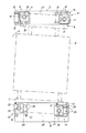
本実施例においては、図1に図示したようにガラス基板2は基板トレイ41に取り付けられており、マスク3は枠状のマスクフレーム(図示省略)に取り付けられ、このマスクフレームは枠状のマスクトレイ42に取り付けられている(基板サイズが第5世代、第5.5世代の場合)。   In this embodiment, as shown in FIG. 1, the glass substrate 2 is attached to the substrate tray 41, the mask 3 is attached to a frame-shaped mask frame (not shown), and this mask frame is a frame-shaped mask. It is attached to the tray 42 (when the substrate size is 5th generation or 5.5th generation).

尚、基板サイズによっては(例えば第6世代の場合)、マスク3をマスクフレームに取り付けたもの(マスクトレイなしのもの)を採用しても良い。   Note that, depending on the substrate size (for example, in the case of the sixth generation), the mask 3 attached to the mask frame (without the mask tray) may be employed.

図1〜4に図示したように、マスクトレイ42の上部には断面視略U字状の上部ガイド体43が設けられている。   As shown in FIGS. 1 to 4, an upper guide body 43 having a substantially U shape in sectional view is provided on the upper portion of the mask tray 42.

この上部ガイド体43の内部には、真空槽1の内部上面側に設けられるガイドローラ40,44が当接する。また、上部ガイド体43の底面には嵌入孔37が設けられ、後述する位置決めピン36を嵌入することで、アライメント時にマスク3を固定できるように構成している。   Inside the upper guide body 43, guide rollers 40 and 44 provided on the inner upper surface side of the vacuum chamber 1 abut. An insertion hole 37 is provided on the bottom surface of the upper guide body 43, and the mask 3 can be fixed during alignment by inserting a positioning pin 36, which will be described later.

マスクトレイ42の下部には丸棒状の下部ガイド体45が設けられている。   A round bar-shaped lower guide body 45 is provided below the mask tray 42.

この下部ガイド体45によりマスク3は真空槽1の内部下面側に設けられる搬送ローラ46(Vローラ)にガイドされつつ搬送される。具体的には搬送ローラ46は真空槽1の底面に立設される。下部ガイド体45の底面には嵌入孔39が設けられ、後述する位置決めピン38を嵌入することで、アライメント時にマスク3を固定できるように構成している。   The mask 3 is conveyed by the lower guide body 45 while being guided by a conveyance roller 46 (V roller) provided on the inner lower surface side of the vacuum chamber 1. Specifically, the transport roller 46 is erected on the bottom surface of the vacuum chamber 1. An insertion hole 39 is provided in the bottom surface of the lower guide body 45, and the mask 3 can be fixed at the time of alignment by inserting a positioning pin 38 to be described later.

また、基板トレイ41にも同様にガイドローラ47が当接する断面視略U字状の上部ガイド体48と、搬送ローラ49(Vローラ)にガイドされつつ搬送される下部ガイド体50が設けられている。この上部ガイド体48の底面及び下部ガイド体50の底面には、基板トレイロックピンが嵌入する嵌入孔が設けられている。   Similarly, the substrate tray 41 is provided with an upper guide body 48 that is substantially U-shaped in cross-section, with which the guide roller 47 abuts, and a lower guide body 50 that is transported while being guided by the transport roller 49 (V roller). Yes. The bottom surface of the upper guide body 48 and the bottom surface of the lower guide body 50 are provided with insertion holes into which the substrate tray lock pins are inserted.

また、基板トレイ41の基板2がクランプ固定されるクランプ固定面の反対側(裏面)には、基板トレイ41を冷却する冷却板及びマスク3(インバーなどの磁性材料からなる)と基板2とを密着させるマグネット板を備えた板体51を設けるための凹部が形成されている。   On the opposite side (back surface) of the substrate tray 41 to which the substrate 2 is clamped and fixed, a cooling plate for cooling the substrate tray 41 and a mask 3 (made of a magnetic material such as Invar) and the substrate 2 are provided. A recess is provided for providing a plate 51 having a magnet plate to be brought into close contact with.

また、基板2の表面側角部及びマスク3の裏面側角部(対角位置の一対の角部)には、アライメントマークが夫々設けられている。   In addition, alignment marks are respectively provided at the front surface side corners of the substrate 2 and the back surface side corners (a pair of corners at diagonal positions) of the mask 3.

このアライメントマークは、基板トレイ41及び板体51に設けたアライメントマーク視認用穴52,53を通じてCCDカメラ、レンズ及び照明から成るアライメントカメラ54により視認できるように構成している。アライメントは、このアライメントカメラ54からの映像を元にアライメント駆動機構を制御して行う。   This alignment mark is configured to be visible by an alignment camera 54 comprising a CCD camera, a lens and illumination through alignment mark visualizing holes 52 and 53 provided in the substrate tray 41 and the plate body 51. The alignment is performed by controlling the alignment drive mechanism based on the image from the alignment camera 54.

アライメント駆動機構について詳述する。   The alignment drive mechanism will be described in detail.

前記上部側移動ベース部6は、前記上部側固定ベース部5に対し前記上部側移動ベース部6をX方向及びY方向に案内する直動案内部を介して前記上部側固定ベース部5に連結し、前記上部側連結体8は、前記各上部側移動ベース部6に対し前記上部側連結体をθ方向に案内する回動案内部を介して前記各上部側移動ベース部6に連結し、前記下部側移動ベース部10は、前記下部側固定ベース部9に対し前記下部側移動ベース部10をX方向及びY方向に案内する直動案内部を介して前記下部側固定ベース部5に連結し、前記下部側連結体12は、前記各下部側移動ベース部10に対し前記下部側連結体12をθ方向に案内する回動案内部を介して前記各下部側移動ベース部10に連結している。   The upper-side moving base portion 6 is connected to the upper-side fixed base portion 5 via a linear motion guide portion that guides the upper-side moving base portion 6 in the X and Y directions with respect to the upper-side fixed base portion 5. The upper-side connecting body 8 is connected to each upper-side moving base portion 6 via a rotation guide portion that guides the upper-side connecting body in the θ direction with respect to each upper-side moving base portion 6. The lower-side moving base portion 10 is connected to the lower-side fixed base portion 5 via a linear motion guide portion that guides the lower-side moving base portion 10 in the X and Y directions with respect to the lower-side fixed base portion 9. The lower-side connecting body 12 is connected to the lower-side moving base portions 10 via a rotation guide portion that guides the lower-side connecting body 12 in the θ direction with respect to the lower-side moving base portions 10. ing.

本実施例においては、上部側固定ベース部5を真空槽1(チャンバ)の上壁面外側に固定状態に設けている。   In this embodiment, the upper fixed base portion 5 is provided in a fixed state outside the upper wall surface of the vacuum chamber 1 (chamber).

図6,7に図示したように、この上部側固定ベース部5のマスク表面と平行な取付面に、X方向(左右方向)に延設されるレール15に断面視コ字状のガイドブロック16を被嵌して成る2つのLM(Linear Motion)ガイドを介して板状の上部側X方向移動ベース14を設け、この上部側X方向移動ベース14のマスク表面と平行な取付面に、Y方向(上下方向)に延設されるレール18にガイドブロック19を被嵌して成る2つのLMガイドを介して板状の上部側Y方向移動ベース17を設けて上部側移動ベース部6を構成している。   As shown in FIGS. 6 and 7, a guide block 16 having a U-shaped cross section in a rail 15 extending in the X direction (left-right direction) on the mounting surface parallel to the mask surface of the upper-side fixed base portion 5. A plate-like upper side X-direction movement base 14 is provided via two LM (Linear Motion) guides formed by fitting the upper side X-direction movement base 14 on the mounting surface parallel to the mask surface of the upper side X-direction. A plate-like upper side Y-direction movement base 17 is provided via two LM guides formed by fitting a guide block 19 on a rail 18 extending in the (vertical direction) to constitute the upper side movement base portion 6. ing.

上部側X方向移動ベース14の上部側固定ベース部5の前記取付面との対向面はマスク表面と平行な面に設定され、この面にガイドブロック16の取付平坦面が取付固定される。また、上部側Y方向移動ベース17の上部側X方向移動ベース14の前記取付面との対向面はマスク表面と平行な面に設定され、この面にガイドブロック19の取付平坦面が取付固定される。   The surface facing the mounting surface of the upper side fixed base portion 5 of the upper side X-direction moving base 14 is set to a surface parallel to the mask surface, and the mounting flat surface of the guide block 16 is mounted and fixed on this surface. Further, the surface of the upper side Y-direction moving base 17 facing the mounting surface of the upper side X-direction moving base 14 is set to a surface parallel to the mask surface, and the mounting flat surface of the guide block 19 is attached and fixed to this surface. The

下部側も同様に、下部側固定ベース部9を真空槽1の下壁面外側に固定状態に設けている。   Similarly, the lower side fixed base portion 9 is provided in a fixed state outside the lower wall surface of the vacuum chamber 1 on the lower side.

この下部側固定ベース部9のマスク表面と平行な取付面に、Y方向に延設されるレール21にガイドブロック22を被嵌して成る2つのLMガイドを介して板状の下部側Y方向移動ベース20を設け、この下部側Y方向移動ベース20のマスク表面と平行な取付面に、X方向に延設されるレール24にガイドブロック25を被嵌して成る2つのLMガイドを介して板状の下部側X方向移動ベース23を設けて下部側移動ベース部10を構成している。   A plate-like lower side Y direction through two LM guides formed by fitting a guide block 22 on a rail 21 extending in the Y direction on a mounting surface parallel to the mask surface of the lower side fixed base portion 9 A movable base 20 is provided, and two LM guides are formed by fitting a guide block 25 to a rail 24 extending in the X direction on a mounting surface parallel to the mask surface of the lower Y-direction movable base 20. A plate-like lower side X-direction moving base 23 is provided to constitute the lower side moving base portion 10.

下部側Y方向移動ベース20の下部側固定ベース部9の前記取付面との対向面はマスク表面と平行な面に設定され、この面にガイドブロック22の取付平坦面が取付固定される。また、下部側X方向移動ベース23の下部側Y方向移動ベース20の前記取付面との対向面はマスク表面と平行な面に設定され、この面にガイドブロック25の取付平坦面が取付固定される。   The surface facing the mounting surface of the lower side fixed base portion 9 of the lower side Y-direction moving base 20 is set to a surface parallel to the mask surface, and the mounting flat surface of the guide block 22 is mounted and fixed on this surface. Further, the lower surface of the lower X direction moving base 23 and the mounting surface of the lower Y direction moving base 20 facing the mounting surface are set parallel to the mask surface, and the mounting flat surface of the guide block 25 is fixedly mounted on this surface. The

尚、本実施例においては、バランスを考慮して、上下の駆動機構でX方向移動ベースとY方向移動ベースの上下配置関係を逆にしているが、一致させても良い。   In this embodiment, considering the balance, the vertical arrangement relationship between the X-direction moving base and the Y-direction moving base is reversed by the upper and lower drive mechanisms, but they may be matched.

また、上部側移動ベース部6及び下部側移動ベース部10は夫々、左右一対ずつ(2つずつ)設けている。   Moreover, the upper side moving base part 6 and the lower side moving base part 10 are provided in pairs (two each) on the left and right sides.

この各上部側移動ベース部6のマスク表面と平行な取付面には、内輪に対して外輪を旋回可能に設けたクロスローラベアリング13を介して上部側連結体8の断面視L字状の板材から成る1つの基部27の垂直面を夫々設け、この基部27は各上部側移動ベース部6に架設状態に設けている。   On the mounting surface parallel to the mask surface of each upper side moving base portion 6, a cross-sectional bearing L-shaped plate member of the upper side connecting body 8 is provided via a cross roller bearing 13 provided so that the outer ring can turn with respect to the inner ring. A vertical surface of one base portion 27 is provided, and the base portion 27 is provided on each upper moving base portion 6 in a erected state.

下部側も同様に、各下部側移動ベース部10のマスク表面と平行な取付面には、内輪に対して外輪を旋回可能に設けたクロスローラベアリング26を介して下部側連結体12の断面視L字状の板材から成る1つの基部29の垂直面を夫々設けて、この基部29を各下部側移動ベース部6に架設状態に設けている。   Similarly, on the lower side, a cross-sectional view of the lower coupling body 12 is provided on the mounting surface parallel to the mask surface of each lower side moving base portion 10 via a cross roller bearing 26 provided so that the outer ring can turn with respect to the inner ring. A vertical surface of one base portion 29 made of an L-shaped plate material is provided, and the base portion 29 is provided in a state of being erected on each lower-side moving base portion 6.

上部側移動ベース部6に設けた上部側連結体8の基部27の前記垂直面と直交する水平面の左右端部(クロスローラベアリング13に対応する位置)には夫々、マスク3を直立状態で取り付けるアライメント枠4に連結される連結筒体28を立設している。   The mask 3 is attached in an upright state to the left and right ends (positions corresponding to the cross roller bearings 13) of the horizontal plane orthogonal to the vertical surface of the base portion 27 of the upper side connecting body 8 provided on the upper side moving base portion 6, respectively. A connecting cylinder 28 connected to the alignment frame 4 is erected.

この各連結筒体28の先端部は真空槽1の上部貫通孔7を通じて真空槽1内に導入され、この先端部にはマスク搬送ガイド用の(マスク位置決め固定位置における)ガイドローラ44が設けられアライメント枠4と連結される水平板体30が架設状態に連結される。このガイドローラ44は、図5に図示したように、上部ガイド体43の内底面に当接するローラ体70と、内側面に当接するローラ体71と、これらのローラ体70,71が回転自在に保持されるローラ保持体72と、ローラ保持体72を水平板体30の表面に対して接離動自在に支持する一対のスライドブッシュ73とで構成されている。また、このローラ保持体72はスプリング等の付勢機構により水平板体30から離反する方向に付勢されている。   The leading end of each connecting cylinder 28 is introduced into the vacuum chamber 1 through the upper through-hole 7 of the vacuum chamber 1, and a guide roller 44 (in the mask positioning and fixing position) is provided at this leading end for guiding the mask. A horizontal plate 30 connected to the alignment frame 4 is connected in an erected state. As shown in FIG. 5, the guide roller 44 includes a roller body 70 that contacts the inner bottom surface of the upper guide body 43, a roller body 71 that contacts the inner surface, and these roller bodies 70 and 71 are rotatable. The roller holder 72 is held, and a pair of slide bushes 73 that support the roller holder 72 so as to be movable toward and away from the surface of the horizontal plate 30. The roller holder 72 is biased in a direction away from the horizontal plate 30 by a biasing mechanism such as a spring.

また、水平板体30には、先端にマスク3の嵌入孔37に嵌入される嵌入部を有する位置決めピン36が設けられている。この位置決めピン36は、ガイドローラ44のスライドブッシュ73間に設けられ、また、その先端部がガイドローラ44のローラ保持体72の中央部に設けられる挿通孔から突出するように設けられる。また、位置決めピン36の先端の嵌入部は、常態ではローラ体70,71より突出しないように構成され、ローラ保持体72が付勢機構による付勢力に抗して押し上げられた場合にはローラ体70,71より突出して(露出して)上部ガイド体43の嵌入孔37に嵌入できるように構成されている。   Further, the horizontal plate 30 is provided with a positioning pin 36 having a fitting portion to be fitted into the fitting hole 37 of the mask 3 at the tip. The positioning pin 36 is provided between the slide bushes 73 of the guide roller 44, and the tip thereof is provided so as to protrude from an insertion hole provided at the center of the roller holder 72 of the guide roller 44. The insertion portion at the tip of the positioning pin 36 is normally configured not to protrude from the roller bodies 70 and 71. When the roller holding body 72 is pushed up against the urging force of the urging mechanism, the roller body It is configured so as to protrude (exposure) from 70 and 71 and be fitted into the fitting hole 37 of the upper guide body 43.

従って、後述する位置決めピン38によりマスク3(マスクトレイ42)が上方に押し上げられ、上部ガイド体43によりローラ体70を介してローラ保持体72が押し上げられると位置決めピン36の先端の嵌入部が露出し、上部ガイド体43の嵌入孔37に嵌入されることになる。   Accordingly, when the mask 3 (mask tray 42) is pushed upward by a positioning pin 38, which will be described later, and the roller holder 72 is pushed up by the upper guide body 43 via the roller body 70, the fitting portion at the tip of the positioning pin 36 is exposed. Then, it is inserted into the insertion hole 37 of the upper guide body 43.

また、この連結筒体28を覆うように金属製のベローズ34(伸縮管)が設けられる。ベローズ34の一端は上部貫通孔7の周縁部に配置され、他端は水平板体30の上面側に配置され、これにより上部貫通孔7は気密状態で封止される。   Further, a metal bellows 34 (expandable tube) is provided so as to cover the connecting cylinder 28. One end of the bellows 34 is disposed at the peripheral edge of the upper through hole 7, and the other end is disposed on the upper surface side of the horizontal plate 30, whereby the upper through hole 7 is sealed in an airtight state.

下部側は、下部側移動ベース部10に設けた下部側連結体12の基部29の前記垂直面と直交する水平面の左右端部(クロスローラベアリング26に対応する位置)には夫々、マスク3を直立状態で取り付けるアライメント枠4に連結される連結筒体31を立設している。   The lower side is provided with masks 3 at left and right end portions (positions corresponding to the cross roller bearings 26) of the horizontal plane orthogonal to the vertical surface of the base portion 29 of the lower side connecting body 12 provided on the lower side moving base portion 10, respectively. A connecting cylinder 31 connected to the alignment frame 4 attached in an upright state is erected.

この各連結筒体31の先端部は真空槽1の下部貫通孔11を通じて真空槽1内に導入され、この先端部にはアライメント枠4と連結される水平板体33が架設状態に連結される。   The distal end portion of each connecting cylinder 31 is introduced into the vacuum chamber 1 through the lower through hole 11 of the vacuum chamber 1, and a horizontal plate 33 connected to the alignment frame 4 is connected to the distal end portion in an erected state. .

この連結筒体31の先端部は水平板体33を(隙間がない気密を保持できる状態で)貫通して上方に突出するように設け、この連結筒体31内に連結筒体31の先端から隙間がない気密を保持できる状態で突出する筒状体60を設け、この筒状体60の内部には位置決めピン38が偏心カム機構等の適宜な突没駆動機構61により先端から突没動自在に設けられている。また、位置決めピン38の突出量は、嵌入孔39に嵌入して少なくともマスクトレイ42の下部ガイド体50が搬送ローラ46から離反するように押し上げられ、マスクトレイ42の上部ガイド体43によりローラ体70を介してローラ保持体72を押し上げて位置決めピン36の先端の嵌入部が露出し得る程度に設定する。   The connecting cylinder 31 has a leading end that passes through the horizontal plate 33 (in a state where airtightness without gaps can be maintained) and protrudes upward, and is inserted into the connecting cylinder 31 from the leading end of the connecting cylinder 31. A cylindrical body 60 that protrudes in a state that can maintain airtightness without a gap is provided, and a positioning pin 38 can be protruded and retracted from the tip by an appropriate protruding and retracting drive mechanism 61 such as an eccentric cam mechanism inside the cylindrical body 60. Is provided. Further, the protruding amount of the positioning pin 38 is pushed up so that at least the lower guide body 50 of the mask tray 42 is separated from the conveying roller 46 by being inserted into the insertion hole 39, and the roller body 70 is driven by the upper guide body 43 of the mask tray 42. The roller holding body 72 is pushed up through the position so that the insertion portion at the tip of the positioning pin 36 can be exposed.

尚、位置決めピン38の外周面と筒状体60の先端内周面とは気密を保持した状態で突没摺動し得るように構成している。   The outer peripheral surface of the positioning pin 38 and the inner peripheral surface of the distal end of the cylindrical body 60 are configured to be able to slide into and out while maintaining airtightness.

従って、この位置決めピン38を筒状体60の先端から突出せしめてマスク3の嵌入孔39に嵌入すると共に、マスク3(マスクトレイ42)を押し上げて上部ガイド体43によりローラ保持体72を押し上げて露出した位置決めピン36の先端の嵌入部を嵌入孔37に嵌入することで、マスク3を上部側連結体8及び下部側連結体12に対して位置決め固定することができ、マスク3をアライメント枠4と一体に固定することができる。   Accordingly, the positioning pin 38 protrudes from the tip of the cylindrical body 60 and is inserted into the insertion hole 39 of the mask 3, and the mask 3 (mask tray 42) is pushed up and the roller holding body 72 is pushed up by the upper guide body 43. The mask 3 can be positioned and fixed with respect to the upper connection body 8 and the lower connection body 12 by inserting the exposed insertion portion of the exposed positioning pin 36 into the insertion hole 37, and the mask 3 is aligned with the alignment frame 4. Can be fixed together.

また、この連結筒体31を覆うように金属製のベローズ35が設けられる。ベローズ35の一端は下部貫通孔11の周縁部に配置され、他端は水平板体33の下面側に配置され、これにより下部貫通孔11は気密状態で封止される。   In addition, a metal bellows 35 is provided so as to cover the connecting cylinder 31. One end of the bellows 35 is disposed on the peripheral edge of the lower through hole 11, and the other end is disposed on the lower surface side of the horizontal plate 33, whereby the lower through hole 11 is sealed in an airtight state.

また、アライメント枠4はその上下端部が夫々水平板体30,33に連結されている。従って、アライメント枠4と各連結体8,12とは一体で移動することになる。即ち、アライメント枠4は、左右の移動ベース部6,10夫々の移動の影響を受けてX,Y及びθの各方向へ移動する各連結体8,12と共にX,Y及びθの各方向へ移動する。尚、アライメント枠4にはマスク冷却用の冷却機構が設けられている。   The alignment frame 4 has upper and lower ends connected to the horizontal plates 30 and 33, respectively. Therefore, the alignment frame 4 and the coupling bodies 8 and 12 move together. That is, the alignment frame 4 is moved in the X, Y, and θ directions together with the coupling bodies 8 and 12 that move in the X, Y, and θ directions under the influence of the movement of the left and right moving base portions 6 and 10. Moving. The alignment frame 4 is provided with a cooling mechanism for cooling the mask.

各移動ベース部6,10を移動させる駆動機構について詳述する。   A drive mechanism for moving the respective movement base units 6 and 10 will be described in detail.

本実施例においては、上部側駆動機構及び下部側駆動機構に、夫々X方向用駆動装置若しくはY方向用駆動装置またはその双方を設け、このX方向用駆動装置及びY方向用駆動装置により前記上部側移動ベース部6及び前記下部側移動ベース部10を上部側固定ベース部5及び下部側固定ベース部9に対してX方向及びY方向に移動せしめることで、前記上部側連結体8及び前記下部側連結体12を介して前記アライメント枠4をX,Y及びθ方向に調整移動し得るように構成している。   In this embodiment, the upper side drive mechanism and the lower side drive mechanism are each provided with an X-direction drive device and / or a Y-direction drive device, and the X-direction drive device and the Y-direction drive device provide the upper part. By moving the side moving base portion 6 and the lower side moving base portion 10 in the X direction and the Y direction with respect to the upper side fixed base portion 5 and the lower side fixed base portion 9, the upper side connecting body 8 and the lower side moving base portion 10 are moved. The alignment frame 4 can be adjusted and moved in the X, Y, and θ directions via the side coupling body 12.

具体的には、X方向用駆動装置及びY方向用駆動装置としては公知のボールねじ装置を採用している。ボールねじ装置は、正逆回転自在のモーター55及びモーター55により回動するボールねじ56(固定部)と、ボールねじ56に螺合してこのボールねじ56の回動によりボールねじ56の軸方向に移動するナット57(移動部)とで構成される。   Specifically, a known ball screw device is employed as the X-direction drive device and the Y-direction drive device. The ball screw device includes a motor 55 that can rotate forward and backward, and a ball screw 56 (fixed portion) that is rotated by the motor 55, and an axial direction of the ball screw 56 that is engaged with the ball screw 56 and rotated by the ball screw 56. And a nut 57 (moving part) that moves to

本実施例においては、図6に図示したように、下部側固定ベース部9(の取付面)の左右端部にモーター55及びボールねじ56を、このボールねじ56が前記Y方向に延設されるレール21同士の間に該レール21と平行となるように固定し、下部側固定ベース部9の左右端部に設けた下部側移動ベース部10の下部側Y方向移動ベース20の下部側固定ベース部9との対向面に夫々前記ボールねじ56と螺合するナット57を取り付けて、Y方向に駆動せしめるように構成している。   In this embodiment, as shown in FIG. 6, a motor 55 and a ball screw 56 are provided on the left and right ends of the lower fixed base portion 9 (attachment surface thereof), and this ball screw 56 extends in the Y direction. The lower-side fixed base 20 of the lower-side Y-direction moving base 20 of the lower-side moving base 10 provided at the left and right ends of the lower-side fixed base 9 is fixed between the two rails 21 in parallel. A nut 57 that is screwed with the ball screw 56 is attached to the surface facing the base portion 9, and is driven in the Y direction.

また、右端部に設けた下部側移動ベース部10の下部側Y方向移動ベース20にモーター55及びボールねじ56を、このボールねじ56が前記X方向に延設されるレール24同士の間に該レール24と平行となるように固定し、下部側X方向移動ベース23の下部側Y方向移動ベース20との対向面に前記ボールねじ56と螺合するナット57を取り付けて、X方向に駆動せしめるように構成している。   Further, a motor 55 and a ball screw 56 are placed on the lower side Y-direction moving base 20 of the lower side moving base portion 10 provided at the right end, and the ball screw 56 extends between the rails 24 extending in the X direction. A nut 57 that is screwed with the ball screw 56 is attached to the surface of the lower side X-direction moving base 23 that faces the lower side Y-direction moving base 20 and is driven in the X direction. It is configured as follows.

また、上部側固定ベース部5(の取付面)の一端部(右端部)にモーター55及びボールねじ56を、このボールねじ56が前記X方向に延設されるレール15同士の間に該レール15と平行となるように固定し、上部側固定ベース部5の右端部に設けた上部側移動ベース部6の上部側X方向移動ベース14の上部側固定ベース部5との対向面に夫々前記ボールねじ56と螺合するナット57を取り付けて、X方向に駆動せしめるように構成している。   Further, a motor 55 and a ball screw 56 are provided at one end (right end) of the upper side fixed base portion 5 (attachment surface thereof), and the rail is provided between the rails 15 where the ball screw 56 extends in the X direction. 15 is fixed to be parallel to the upper side fixed base portion 5, and the upper side moving base portion 6 provided at the right end of the upper side fixed base portion 5 is opposed to the upper side fixed base portion 5 of the upper side X-direction moving base 14. A nut 57 to be screwed with the ball screw 56 is attached and configured to be driven in the X direction.

従って、上部側連結体8及び下部側連結体12とアライメント枠4とは一体に移動することから、上記4つのボールねじ装置(以下、下部側X方向用駆動装置をA,下部左側Y方向用駆動装置をB,下部右側Y方向用駆動装置をC,上部側X方向駆動用装置をDとする。)による各移動ベースの移動量を調整することで、上部側連結体8及び下部側連結体12とアライメント枠4とをX,Y及びθ方向に自在に移動させることができる。   Accordingly, since the upper side connecting body 8 and the lower side connecting body 12 and the alignment frame 4 move together, the above four ball screw devices (hereinafter, the lower side X direction driving device is referred to as A, lower left side Y direction). By adjusting the amount of movement of each moving base by B as the driving device, C as the driving device for the lower right Y direction, and D as the driving device for the upper X direction, the upper connecting body 8 and the lower side connecting body are adjusted. The body 12 and the alignment frame 4 can be moved freely in the X, Y, and θ directions.

例えば、図7に図示したように、Aにより下部側X方向移動ベース23を左方向に送り、Dにより上部側X方向移動ベース14を右方向に送り、Bにより左側の下部側Y方向移動ベース20を上方向に送り、Cにより右側の下部側Y方向移動ベース20を下方向に送ることで、クロスローラベアリングを介してアライメント枠4(マスク3)を回転させることもでき、これらA〜Dによる送り方向及び送り量を夫々独立して制御することで、アライメントマークに基づいてマスク3を精密に基板2に対する位置合わせを行うことが可能となる。   For example, as shown in FIG. 7, the lower side X-direction moving base 23 is sent leftward by A, the upper side X-direction moving base 14 is sent rightward by D, and the lower side Y-direction moving base left is sent by B. The alignment frame 4 (mask 3) can also be rotated via the cross roller bearing by feeding 20 upward and feeding the lower Y-direction moving base 20 on the right side downward by C. By independently controlling the feeding direction and the feeding amount according to, the mask 3 can be precisely aligned with the substrate 2 based on the alignment mark.

また、本実施例においては、下部側駆動機構でアライメント枠4及びマスク3の質量を支持する必要があるため、負荷に見合ったエアー圧を供給することで質量をキャンセルしてY軸の駆動負荷を低減させるバランサーシリンダ62を設けている。尚、下部側駆動機構との結合部はアライメント動作を制限しないようにLMガイド63を介して結合している。   Further, in this embodiment, since it is necessary to support the mass of the alignment frame 4 and the mask 3 by the lower side drive mechanism, the mass is canceled by supplying air pressure corresponding to the load, and the Y-axis drive load A balancer cylinder 62 for reducing the above is provided. The connecting portion with the lower drive mechanism is connected via an LM guide 63 so as not to limit the alignment operation.

また、本実施例において、基板2のロック機構及びマスク3に対する往復移動機構は、以下のように構成している。   In this embodiment, the lock mechanism for the substrate 2 and the reciprocating mechanism for the mask 3 are configured as follows.

基板2のロック機構は、図3,4に図示したように、基板2(基板トレイ41)を上昇させる偏心カム32と、偏心カム32により上昇させた基板トレイ41の下部ガイド体50の底面の嵌入孔に嵌入する基板トレイロックピン(偏心カム32と共にマスク3に対して往復移動する)と、基板トレイ41が上昇した際、上部ガイド体48の底面に設けたV字溝に嵌入するガイドローラ47のテーパ状ローラ体とで構成している。   As shown in FIGS. 3 and 4, the lock mechanism of the substrate 2 includes an eccentric cam 32 that raises the substrate 2 (substrate tray 41), and a bottom surface of the lower guide body 50 of the substrate tray 41 that is raised by the eccentric cam 32. A substrate tray lock pin (moves back and forth with respect to the mask 3 together with the eccentric cam 32) to be inserted into the insertion hole, and a guide roller to be inserted into a V-shaped groove provided on the bottom surface of the upper guide body 48 when the substrate tray 41 is raised. It consists of 47 tapered roller bodies.

また、マスク3に対する往復移動機構は、図3,4に図示したように、偏心カム32を支持する支持体66と、ガイドローラ47を支持する支持体69と、これら支持体66,69を真空槽1に対してマスク3の面方向と水平方向に直交する方向にスライド自在に支持するLMガイド67と、これら支持体66,69をスライド移動させるスライド移動機構75とで構成している。このスライド移動機構75は、サーボモーター及びこのサーボモーターにより駆動するボールねじユニットと、このボールねじユニットによりLMガイド76に沿ってマスク3の面方向と水平方向に直交する方向に移動する移動ベース78と、この移動ベース78と支持体66,69とを連結する連結部74とで構成している。   As shown in FIGS. 3 and 4, the reciprocating mechanism with respect to the mask 3 includes a support 66 for supporting the eccentric cam 32, a support 69 for supporting the guide roller 47, and vacuuming the supports 66 and 69. The LM guide 67 is slidably supported with respect to the tank 1 in a direction orthogonal to the surface direction of the mask 3 and the horizontal direction, and a slide moving mechanism 75 for slidingly moving these supports 66 and 69. The slide moving mechanism 75 includes a servo motor and a ball screw unit driven by the servo motor, and a moving base 78 that moves in the direction perpendicular to the surface direction of the mask 3 along the LM guide 76 by the ball screw unit. And a connecting portion 74 that connects the moving base 78 and the supports 66 and 69.

図中、符号64は偏心カム32を回転させる回転軸、65は回転軸64を駆動する駆動モーター、68は往復移動機構によりマスク3に対して基板2を押し付けた際の過度の密着を防止するためのスプリング、77はベローズである。   In the figure, reference numeral 64 is a rotating shaft for rotating the eccentric cam 32, 65 is a drive motor for driving the rotating shaft 64, and 68 is a reciprocating mechanism for preventing excessive adhesion when the substrate 2 is pressed against the mask 3. The spring 77 is a bellows.

以上の構成の本実施例によるアライメント動作を説明する。   An alignment operation according to the present embodiment having the above configuration will be described.

成膜室にマスク3及び基板2を搬送機構(搬送ローラ及びガイドローラ)により夫々搬送する。尚、本実施例においてはこれらの搬送ローラ及びガイドローラを搬送方向と水平方向に直交する方向にマスク搬送用及び基板搬送用2列並設している。勿論3列以上並設しても良い。   The mask 3 and the substrate 2 are transferred to the film forming chamber by a transfer mechanism (transfer roller and guide roller), respectively. In this embodiment, these transport rollers and guide rollers are arranged in parallel in two rows for mask transport and substrate transport in a direction perpendicular to the transport direction and the horizontal direction. Of course, three or more rows may be juxtaposed.

成膜室に搬送されたマスク3及び基板2を夫々、マスク3及び基板2をアーム等で機械的に仮位置決めするプリアライメント機構により、位置決めピン36,38及び基板トレイロックピンが夫々嵌入孔に嵌入し得る位置に調整移動する。   The positioning pins 36 and 38 and the substrate tray lock pin are respectively inserted into the insertion holes by a pre-alignment mechanism that mechanically temporarily positions the mask 3 and the substrate 2 transferred to the film forming chamber with an arm or the like. Adjust and move to a position where it can be inserted.

プリアライメントされたマスク3の嵌入孔37,39に、位置決めピン36,38を嵌入せしめ、マスク3(マスクトレイ42)を各連結体8,12に対して固定する。   Positioning pins 36 and 38 are inserted into the insertion holes 37 and 39 of the pre-aligned mask 3, and the mask 3 (mask tray 42) is fixed to the coupling bodies 8 and 12.

また、基板2については基板トレイロックピンを上昇させつつ搬送ローラのうちの一部の偏心カム32の回転により基板トレイ41を上昇させてアライメント位置(マスク3と基板2のアライメントマークがある程度重なる位置)に移動せしめ(図3)、このアライメント位置で基板トレイロックピンを嵌入孔に嵌入せしめ、真空槽1に対して固定する。   For the substrate 2, while raising the substrate tray lock pin, the substrate tray 41 is raised by the rotation of a part of the eccentric cam 32 of the transport roller, and the alignment position (the position where the alignment mark of the mask 3 and the substrate 2 overlaps to some extent). The substrate tray lock pin is inserted into the insertion hole at this alignment position and fixed to the vacuum chamber 1.

基板2を計測位置に移動させた後、CCDカメラにて取得したアライメントマークの位置情報をもとに駆動制御装置内でマスクトレイ42の位置補正量を算出し、この位置補正量からアライメント枠4及びマスク3の移動量(各X方向用駆動装置及びY方向用駆動装置による送り量)を算出し、この算出した移動量を元に各駆動装置を駆動せしめてアライメント(マスク3の基板2に対する位置合わせ)を行う。   After the substrate 2 is moved to the measurement position, the position correction amount of the mask tray 42 is calculated in the drive control device based on the position information of the alignment mark acquired by the CCD camera, and the alignment frame 4 is calculated from this position correction amount. And the movement amount of the mask 3 (feed amount by each X-direction drive device and Y-direction drive device) is calculated, and each drive device is driven based on the calculated movement amount to align the mask 3 with respect to the substrate 2. Align).

アライメント終了後、基板2をマスク3に近接するように往復移動機構により移動せしめ(図4)、基板2とマスク3とを密着させて基板トレイ41の凹部に冷却板及びマグネット板を備えた板体51を設け、この状態でCCDカメラにてアライメントマークの位置情報を取得し、位置合わせが基準寸法内に収まっているかを駆動制御装置で判定し、アライメントマークのズレが基準寸法内であればそのまま成膜を開始し、基準寸法内でなければ前記位置補正量及び前記移動量を算出して基準寸法内になるまで繰り返しアライメントを行う。   After the alignment, the substrate 2 is moved by a reciprocating mechanism so as to be close to the mask 3 (FIG. 4), the substrate 2 and the mask 3 are brought into close contact with each other, and a plate provided with a cooling plate and a magnet plate in the concave portion of the substrate tray 41. In this state, the position information of the alignment mark is obtained by the CCD camera, and the drive control device determines whether the alignment is within the reference dimension. If the alignment mark is within the reference dimension, The film formation is started as it is, and if it is not within the reference dimension, the position correction amount and the movement amount are calculated, and the alignment is repeated until it is within the reference dimension.

尚、本実施例においては、マスク3側を動かすことでアライメントを行っているが、基板2側を動かすように同様に構成しても良い。また、本実施例においては、真空槽1の上下に夫々上部側駆動機構及び下部側駆動機構を設けた構成であるが、X方向用駆動装置及びY方向用駆動装置を備えた上部側駆動機構若しくは下部側駆動機構のみを設ける構成としても良い。   In this embodiment, the alignment is performed by moving the mask 3 side, but it may be configured similarly so as to move the substrate 2 side. In this embodiment, the upper side driving mechanism and the lower side driving mechanism are provided above and below the vacuum chamber 1, respectively, but the upper side driving mechanism provided with the X direction driving device and the Y direction driving device. Or it is good also as a structure which provides only a lower side drive mechanism.

本実施例は上述のように構成したから、真空槽1から成る成膜室(チャンバ)内に直立状態で搬送される基板2とマスク3との位置合わせを、上部側移動ベース部6及び下部側移動ベース部10を夫々上下の各固定ベース部5,9に対して移動せしめ、この上下の各移動ベース部6,10に設けられる上部側連結体8及び下部側連結体12を介してアライメント枠4及びこのアライメント枠4と一体に移動するように取り付けられるマスク3を基板2に対してX,Y及びθ方向に調整移動することで行うため、従来のようにアライメント駆動機構を搬送方向と水平方向に直交する方向に突出させることなく、真空槽1の上下にコンパクトに分割配置することが可能となり、それだけ平面レイアウト上の設置スペースを可及的に小さくすることができる。   Since the present embodiment is configured as described above, the alignment of the substrate 2 and the mask 3 conveyed in an upright state in the film forming chamber (chamber) including the vacuum chamber 1 is performed by using the upper-side moving base portion 6 and the lower portion. The side moving base portion 10 is moved with respect to the upper and lower fixed base portions 5 and 9, respectively, and alignment is performed via the upper side connecting body 8 and the lower side connecting body 12 provided on the upper and lower moving base portions 6 and 10, respectively. Since the frame 4 and the mask 3 attached so as to move integrally with the alignment frame 4 are adjusted and moved in the X, Y, and θ directions with respect to the substrate 2, the alignment drive mechanism is set in the transport direction as in the prior art. Without projecting in a direction perpendicular to the horizontal direction, the vacuum chamber 1 can be divided and arranged in a compact manner, and the installation space on the planar layout can be made as small as possible.

また、剛体としてのチャンバに各固定ベース部5,9を設けるため、位置合わせ精度も十分確保することができる。また、中央の空間部分を大きくすることができ、マスク冷却機構や基板吸着機構等の設置がそれだけ容易となる。更に、マスク3の保持モーメントが小さくなり、位置合わせ精度に対する影響を少なくでき、それだけ基板サイズの大型化に対応できるものとなる。従って、駆動機構を上下に分割してそれだけコンパクトにでき、また、この駆動機構と各連結体8,12のアライメント枠4との連結部との距離を短くできるため、それだけ精密な位置合わせ調整移動が可能となる。   Moreover, since each fixed base part 5 and 9 is provided in the chamber as a rigid body, sufficient alignment accuracy can be ensured. In addition, the central space can be enlarged, and installation of a mask cooling mechanism, a substrate suction mechanism, and the like is facilitated accordingly. Further, the holding moment of the mask 3 is reduced, the influence on the alignment accuracy can be reduced, and the increase in the substrate size can be dealt with. Therefore, the drive mechanism can be divided into upper and lower parts, and the distance between the drive mechanism and the connecting portion between the connecting bodies 8 and 12 can be shortened. Is possible.

また、上下の各移動ベース部6,10を移動させるための駆動装置を、真空槽1の上部及び下部に夫々分割して設けることができ、所定間隔をおいて設けた一対(2つ)の下部側移動ベース部10を下部側固定ベース部9に対してX方向に移動させるボールねじ装置(1軸)及びY方向に移動させるボールねじ装置(各移動ベース部に夫々計2軸)を下部側に設け、上部側移動ベース部6を上部側固定ベース部5に対してX方向に移動させるボールねじ機構(1軸)を上部側に設け、各駆動装置による各移動ベース部の移動量を調整設定することで、アライメント枠4をX,Y及びθ方向に自在に調整移動させることができ、しかも、上部側の駆動装置を少なくしてより安定的に真空槽にアライメント駆動機構を設けることなどが可能となる。   In addition, a driving device for moving the upper and lower moving base parts 6 and 10 can be provided separately on the upper and lower parts of the vacuum chamber 1, and a pair (two) of them provided at a predetermined interval. A ball screw device (one axis) for moving the lower side moving base portion 10 in the X direction relative to the lower side fixed base portion 9 and a ball screw device for moving in the Y direction (two axes for each moving base portion, respectively) on the lower side A ball screw mechanism (one axis) for moving the upper side moving base portion 6 in the X direction with respect to the upper side fixed base portion 5 is provided on the upper side, and the amount of movement of each moving base portion by each driving device is set. By adjusting and setting, the alignment frame 4 can be adjusted and moved freely in the X, Y, and θ directions, and the alignment drive mechanism can be provided in the vacuum chamber more stably by reducing the number of upper drive devices. It becomes possible.

更に、真空槽1内(真空側)に配置されるのは各連結体8,12のアライメント枠4との連結部のみであり、アライメント駆動機構の摩擦接触部位が全て真空槽1の外部(大気側)に設けられるため、それだけ真空槽1の内部を清浄な雰囲気に保持することができ、成膜される薄膜をより高品質なものとすることが可能となる。   Further, only the connection parts of the respective connecting bodies 8 and 12 to the alignment frame 4 are arranged in the vacuum chamber 1 (vacuum side), and all the frictional contact portions of the alignment drive mechanism are outside the vacuum chamber 1 (atmosphere). Therefore, the interior of the vacuum chamber 1 can be maintained in a clean atmosphere, and the thin film to be formed can be of higher quality.

よって、本実施例は、位置合わせ精度を確保しつつ省スペースを実現し、第四世代以上の大型基板にも対応可能な極めて実用性に秀れたものとなる。   Therefore, the present embodiment achieves space saving while ensuring alignment accuracy, and is extremely practical for handling large substrates of the fourth generation or higher.

真空槽
2 基板
3 マスク
4 アライメント枠
5 上部側固定ベース部
6 上部側移動ベース部
7 上部貫通孔
8 上部側連結体
9 下部側固定ベース部
10 下部側移動ベース部
11 下部貫通孔
12 下部側連結体
34,35 ベローズ
DESCRIPTION OF SYMBOLS 1 Vacuum chamber 2 Board | substrate 3 Mask 4 Alignment frame 5 Upper side fixed base part 6 Upper side movement base part 7 Upper through-hole 8 Upper side coupling body 9 Lower side fixed base part
10 Lower side moving base
11 Lower through hole
12 Lower side connector
34, 35 Bellows

Claims (6)

真空槽内で直立状態に保持された基板にマスクを介して成膜材料を付着せしめて成膜を行う成膜装置であって、前記マスクを直立状態に取り付けたアライメント枠を前記基板に対して調整移動して、前記マスクが前記基板に対して適正位置となるように前記マスクと前記基板との位置合わせを行うアライメント駆動機構を備え、このアライメント駆動機構は、前記真空槽の外部に設けられこの真空槽の上部側に固定される上部側固定ベース部と、この上部側固定ベース部に対してマスク表面に平行なX方向及びY方向に移動可能な上部側移動ベース部と、一端が前記マスク表面上の回転方向であるθ方向に回転自在に前記上部側移動ベース部に支持され、他端が前記真空槽の上部に設けた上部貫通孔を通じて前記真空槽内の前記アライメント枠の上部に連結する上部側連結体とから成る上部側駆動機構か若しくは、前記真空槽の外部に設けられこの真空槽の下部側に固定される下部側固定ベース部と、この下部側固定ベース部に対してマスク表面に平行なX方向及びY方向に移動可能な下部側移動ベース部と、一端が前記マスク表面上の回転方向であるθ方向に回転自在に前記下部側移動ベース部に支持され、他端が前記真空槽の下部に設けた下部貫通孔を通じて前記真空槽内の前記アライメント枠の下部に連結する下部側連結体とから成る下部側駆動機構で構成し、前記上部側連結体及び前記下部側連結体の前記アライメント枠との連結部は前記上部貫通孔及び前記下部貫通孔を夫々気密状態で封止するベローズを介して前記真空槽内に設けたことを特徴とする成膜装置。   A film forming apparatus for forming a film by attaching a film forming material to a substrate held in an upright state in a vacuum chamber through a mask, and an alignment frame attached with the mask in an upright state with respect to the substrate An alignment drive mechanism is provided that adjusts and moves the mask and the substrate so that the mask is in an appropriate position with respect to the substrate. The alignment drive mechanism is provided outside the vacuum chamber. An upper-side fixed base portion fixed to the upper side of the vacuum chamber, an upper-side moving base portion movable in the X and Y directions parallel to the mask surface with respect to the upper-side fixed base portion, and one end of the upper-side fixed base portion The alignment in the vacuum chamber is supported by the upper moving base portion so as to be rotatable in the θ direction, which is the rotation direction on the mask surface, and the other end through an upper through hole provided in the upper portion of the vacuum chamber. An upper drive mechanism comprising an upper connecting body connected to the upper part of the vacuum chamber, or a lower fixed base portion provided outside the vacuum chamber and fixed to the lower side of the vacuum chamber, and the lower fixed base portion And a lower-side moving base portion that is movable in the X and Y directions parallel to the mask surface, and one end thereof is supported by the lower-side moving base portion so as to be rotatable in the θ direction, which is the rotation direction on the mask surface. The other end is configured by a lower side driving mechanism including a lower side coupling body coupled to a lower portion of the alignment frame in the vacuum chamber through a lower through hole provided in the lower portion of the vacuum chamber, and the upper side coupling body and A film forming apparatus, wherein a connecting portion of the lower side connecting body and the alignment frame is provided in the vacuum chamber via a bellows that seals the upper through hole and the lower through hole in an airtight state. . 真空槽内で直立状態に保持された基板にマスクを介して成膜材料を付着せしめて成膜を行う成膜装置であって、前記マスクを直立状態に取り付けたアライメント枠を前記基板に対して調整移動して、前記マスクが前記基板に対して適正位置となるように前記マスクと前記基板との位置合わせを行うアライメント駆動機構を備え、このアライメント駆動機構は、前記真空槽の外部に設けられこの真空槽の上部側に固定される上部側固定ベース部と、この上部側固定ベース部に対してマスク表面に平行なX方向及びY方向に移動可能な上部側移動ベース部と、一端が前記マスク表面上の回転方向であるθ方向に回転自在に前記上部側移動ベース部に支持され、他端が前記真空槽の上部に設けた上部貫通孔を通じて前記真空槽内の前記アライメント枠の上部に連結する上部側連結体とから成る上部側駆動機構と、前記真空槽の外部に設けられこの真空槽の下部側に固定される下部側固定ベース部と、この下部側固定ベース部に対してマスク表面に平行なX方向及びY方向に移動可能な下部側移動ベース部と、一端が前記マスク表面上の回転方向であるθ方向に回転自在に前記下部側移動ベース部に支持され、他端が前記真空槽の下部に設けた下部貫通孔を通じて前記真空槽内の前記アライメント枠の下部に連結する下部側連結体とから成る下部側駆動機構とで構成し、前記上部側連結体及び前記下部側連結体の前記アライメント枠との連結部は前記上部貫通孔及び前記下部貫通孔を夫々気密状態で封止するベローズを介して前記真空槽内に設けたことを特徴とする成膜装置。   A film forming apparatus for forming a film by attaching a film forming material to a substrate held in an upright state in a vacuum chamber through a mask, and an alignment frame attached with the mask in an upright state with respect to the substrate An alignment drive mechanism is provided that adjusts and moves the mask and the substrate so that the mask is in an appropriate position with respect to the substrate. The alignment drive mechanism is provided outside the vacuum chamber. An upper-side fixed base portion fixed to the upper side of the vacuum chamber, an upper-side moving base portion movable in the X and Y directions parallel to the mask surface with respect to the upper-side fixed base portion, and one end of the upper-side fixed base portion The alignment in the vacuum chamber is supported by the upper moving base portion so as to be rotatable in the θ direction, which is the rotation direction on the mask surface, and the other end through an upper through hole provided in the upper portion of the vacuum chamber. An upper side drive mechanism comprising an upper side connecting body connected to the upper part of the vacuum chamber, a lower side fixed base portion provided outside the vacuum chamber and fixed to the lower side of the vacuum chamber, and a lower side fixed base portion On the other hand, a lower side moving base part movable in the X direction and the Y direction parallel to the mask surface, and one end supported by the lower side moving base part so as to be rotatable in the θ direction which is a rotation direction on the mask surface, The other end is constituted by a lower side driving mechanism comprising a lower side coupling body coupled to a lower portion of the alignment frame in the vacuum chamber through a lower through hole provided in the lower portion of the vacuum chamber, and the upper side coupling body and A film forming apparatus, wherein a connecting portion of the lower side connecting body and the alignment frame is provided in the vacuum chamber via a bellows that seals the upper through hole and the lower through hole in an airtight state. . 真空槽内で直立状態に保持された基板にマスクを介して成膜材料を付着せしめて成膜を行う成膜装置であって、前記マスクを直立状態に取り付けたアライメント枠を前記基板に対して調整移動して、前記マスクが前記基板に対して適正位置となるように前記マスクと前記基板との位置合わせを行うアライメント駆動機構を備え、このアライメント駆動機構は、前記真空槽の外部に設けられこの真空槽の上部側に固定される上部側固定ベース部と、この上部側固定ベース部に対してマスク表面に平行なX方向及びY方向に移動可能な上部側移動ベース部と、一端が前記マスク表面上の回転方向であるθ方向に回転自在に前記上部側移動ベース部に支持され、他端が前記真空槽の上部に設けた上部貫通孔を通じて前記真空槽内の前記アライメント枠の上部に連結する上部側連結体とから成る上部側駆動機構か若しくは、前記真空槽の外部に設けられこの真空槽の下部側に固定される下部側固定ベース部と、この下部側固定ベース部に対してマスク表面に平行なX方向及びY方向に移動可能な下部側移動ベース部と、一端が前記マスク表面上の回転方向であるθ方向に回転自在に前記下部側移動ベース部に支持され、他端が前記真空槽の下部に設けた下部貫通孔を通じて前記真空槽内の前記アライメント枠の下部に連結する下部側連結体とから成る下部側駆動機構で構成し、前記上部側駆動機構若しくは前記下部側駆動機構に、X方向用駆動装置若しくはY方向用駆動装置またはその双方を設け、このX方向用駆動装置及びY方向用駆動装置により前記上部側移動ベース部若しくは前記下部側移動ベース部を上部側固定ベース部若しくは下部側固定ベース部に対してX方向及びY方向に移動せしめることで、前記上部側連結体若しくは前記下部側連結体を介して前記アライメント枠をX,Y及びθ方向に調整移動し得るように構成し、前記上部側連結体及び前記下部側連結体の前記アライメント枠との連結部は前記上部貫通孔及び前記下部貫通孔を夫々気密状態で封止するベローズを介して前記真空槽内に設けたことを特徴とする成膜装置。   A film forming apparatus for forming a film by attaching a film forming material to a substrate held in an upright state in a vacuum chamber through a mask, and an alignment frame attached with the mask in an upright state with respect to the substrate An alignment drive mechanism is provided that adjusts and moves the mask and the substrate so that the mask is in an appropriate position with respect to the substrate. The alignment drive mechanism is provided outside the vacuum chamber. An upper-side fixed base portion fixed to the upper side of the vacuum chamber, an upper-side moving base portion movable in the X and Y directions parallel to the mask surface with respect to the upper-side fixed base portion, and one end of the upper-side fixed base portion The alignment in the vacuum chamber is supported by the upper moving base portion so as to be rotatable in the θ direction, which is the rotation direction on the mask surface, and the other end through an upper through hole provided in the upper portion of the vacuum chamber. An upper drive mechanism comprising an upper connecting body connected to the upper part of the vacuum chamber, or a lower fixed base portion provided outside the vacuum chamber and fixed to the lower side of the vacuum chamber, and the lower fixed base portion And a lower-side moving base portion that is movable in the X and Y directions parallel to the mask surface, and one end thereof is supported by the lower-side moving base portion so as to be rotatable in the θ direction, which is the rotation direction on the mask surface. The lower end drive mechanism comprising a lower side connecting body connected to the lower portion of the alignment frame in the vacuum chamber through a lower through-hole provided at the lower end of the vacuum chamber, and the upper side drive mechanism or The lower-side drive mechanism is provided with an X-direction drive device and / or a Y-direction drive device, and the upper-side moving base portion or the lower portion is provided by the X-direction drive device and the Y-direction drive device. By moving the moving base part in the X direction and the Y direction with respect to the upper fixed base part or the lower fixed base part, the alignment frame is moved to the X, Y via the upper connected body or the lower connected body. And the connecting portion of the upper side connecting body and the lower side connecting body with the alignment frame seals the upper and lower through holes in an airtight state, respectively. A film forming apparatus provided in the vacuum chamber via a bellows. 真空槽内で直立状態に保持された基板にマスクを介して成膜材料を付着せしめて成膜を行う成膜装置であって、前記マスクを直立状態に取り付けたアライメント枠を前記基板に対して調整移動して、前記マスクが前記基板に対して適正位置となるように前記マスクと前記基板との位置合わせを行うアライメント駆動機構を備え、このアライメント駆動機構は、前記真空槽の外部に設けられこの真空槽の上部側に固定される上部側固定ベース部と、この上部側固定ベース部に対してマスク表面に平行なX方向及びY方向に移動可能な上部側移動ベース部と、一端が前記マスク表面上の回転方向であるθ方向に回転自在に前記上部側移動ベース部に支持され、他端が前記真空槽の上部に設けた上部貫通孔を通じて前記真空槽内の前記アライメント枠の上部に連結する上部側連結体とから成る上部側駆動機構と、前記真空槽の外部に設けられこの真空槽の下部側に固定される下部側固定ベース部と、この下部側固定ベース部に対してマスク表面に平行なX方向及びY方向に移動可能な下部側移動ベース部と、一端が前記マスク表面上の回転方向であるθ方向に回転自在に前記下部側移動ベース部に支持され、他端が前記真空槽の下部に設けた下部貫通孔を通じて前記真空槽内の前記アライメント枠の下部に連結する下部側連結体とから成る下部側駆動機構とで構成し、前記上部側駆動機構及び前記下部側駆動機構に、夫々X方向用駆動装置若しくはY方向用駆動装置またはその双方を設け、このX方向用駆動装置及びY方向用駆動装置により前記上部側移動ベース部及び前記下部側移動ベース部を上部側固定ベース部及び下部側固定ベース部に対してX方向及びY方向に移動せしめることで、前記上部側連結体及び前記下部側連結体を介して前記アライメント枠をX,Y及びθ方向に調整移動し得るように構成し、前記上部側連結体及び前記下部側連結体の前記アライメント枠との連結部は前記上部貫通孔及び前記下部貫通孔を夫々気密状態で封止するベローズを介して前記真空槽内に設けたことを特徴とする成膜装置。   A film forming apparatus for forming a film by attaching a film forming material to a substrate held in an upright state in a vacuum chamber through a mask, and an alignment frame attached with the mask in an upright state with respect to the substrate An alignment drive mechanism is provided that adjusts and moves the mask and the substrate so that the mask is in an appropriate position with respect to the substrate. The alignment drive mechanism is provided outside the vacuum chamber. An upper-side fixed base portion fixed to the upper side of the vacuum chamber, an upper-side moving base portion movable in the X and Y directions parallel to the mask surface with respect to the upper-side fixed base portion, and one end of the upper-side fixed base portion The alignment in the vacuum chamber is supported by the upper moving base portion so as to be rotatable in the θ direction, which is the rotation direction on the mask surface, and the other end through an upper through hole provided in the upper portion of the vacuum chamber. An upper side drive mechanism comprising an upper side connecting body connected to the upper part of the vacuum chamber, a lower side fixed base portion provided outside the vacuum chamber and fixed to the lower side of the vacuum chamber, and a lower side fixed base portion On the other hand, a lower side moving base part movable in the X direction and the Y direction parallel to the mask surface, and one end supported by the lower side moving base part so as to be rotatable in the θ direction which is a rotation direction on the mask surface, A lower side drive mechanism comprising a lower side coupling body connected to the lower part of the alignment frame in the vacuum chamber through a lower through hole provided at the lower end of the vacuum chamber, the upper side drive mechanism and The lower drive mechanism is provided with an X-direction drive device and / or a Y-direction drive device, respectively, and the X-direction drive device and the Y-direction drive device respectively provide the upper-side moving base portion and the lower-side moving base. By moving the part in the X direction and the Y direction with respect to the upper side fixed base part and the lower side fixed base part, the alignment frame is moved to the X, Y, and θ via the upper side connected body and the lower side connected body. The upper and lower connection bodies are connected to the alignment frame by a bellows that seals the upper and lower through holes in an airtight state, respectively. The film forming apparatus is provided in the vacuum chamber. 前記マスク表面に平行な上下方向であるY方向に前記下部側移動ベース部を移動せしめる前記下部側駆動機構に設けられる前記Y方向用駆動装置は、前記各下部側移動ベース部を夫々独立して移動可能に構成し、前記上部側駆動機構には前記Y方向用駆動装置を設けないことを特徴とする請求項4に記載の成膜装置。 The Y-direction drive device provided in the lower-side drive mechanism for moving the lower-side movement base portion in the Y direction, which is an up-down direction parallel to the mask surface, each independently moves the lower-side movement base portion. movably constituted, film forming apparatus according to claim 4, in the upper-side drive mechanism, characterized in that it is provided with the Y-direction drive device. 前記上部側移動ベース部は、前記上部側固定ベース部に対し前記上部側移動ベース部をX方向及びY方向に案内する直動案内部を介して前記上部側固定ベース部に連結し、前記上部側連結体は、前記各上部側移動ベース部に対し前記上部側連結体をθ方向に案内する回動案内部を介して前記各上部側移動ベース部に連結し、前記下部側移動ベース部は、前記下部側固定ベース部に対し前記下部側移動ベース部をX方向及びY方向に案内する直動案内部を介して前記下部側固定ベース部に連結し、前記下部側連結体は、前記各下部側移動ベース部に対し前記下部側連結体をθ方向に案内する回動案内部を介して前記各下部側移動ベース部に連結したことを特徴とする請求項4,5のいずれか1項に記載の成膜装置。   The upper-side moving base portion is connected to the upper-side fixed base portion via a linear motion guide portion that guides the upper-side moving base portion with respect to the upper-side fixed base portion in the X direction and the Y direction. The side connection body is connected to each upper side movement base portion via a rotation guide portion that guides the upper side connection body in the θ direction with respect to each upper side movement base portion, and the lower side movement base portion is The lower-side fixed base part is connected to the lower-side fixed base part via a linear motion guide part that guides the lower-side movable base part in the X direction and the Y direction with respect to the lower-side fixed base part. 6. The lower-side moving base portion is connected to each lower-side moving base portion via a rotation guide portion that guides the lower-side connected body in the θ direction with respect to the lower-side moving base portion. 2. The film forming apparatus according to 1.
JP2010220263A 2010-09-30 2010-09-30 Deposition equipment Active JP5639431B2 (en)

Priority Applications (5)

Application Number Priority Date Filing Date Title
JP2010220263A JP5639431B2 (en) 2010-09-30 2010-09-30 Deposition equipment
CN201180046526.8A CN103154304B (en) 2010-09-30 2011-09-05 Film-forming apparatus
PCT/JP2011/070119 WO2012043150A1 (en) 2010-09-30 2011-09-05 Film-forming apparatus
KR1020137006250A KR101846982B1 (en) 2010-09-30 2011-09-05 Film-forming apparatus
TW100134788A TWI585222B (en) 2010-09-30 2011-09-27 Film forming device

Applications Claiming Priority (1)

Application Number Priority Date Filing Date Title
JP2010220263A JP5639431B2 (en) 2010-09-30 2010-09-30 Deposition equipment

Publications (3)

Publication Number Publication Date
JP2012072478A JP2012072478A (en) 2012-04-12
JP2012072478A5 JP2012072478A5 (en) 2013-11-14
JP5639431B2 true JP5639431B2 (en) 2014-12-10

Family

ID=45892623

Family Applications (1)

Application Number Title Priority Date Filing Date
JP2010220263A Active JP5639431B2 (en) 2010-09-30 2010-09-30 Deposition equipment

Country Status (5)

Country Link
JP (1) JP5639431B2 (en)
KR (1) KR101846982B1 (en)
CN (1) CN103154304B (en)
TW (1) TWI585222B (en)
WO (1) WO2012043150A1 (en)

Families Citing this family (31)

* Cited by examiner, † Cited by third party
Publication number Priority date Publication date Assignee Title
JP2014015633A (en) * 2012-07-05 2014-01-30 Sumitomo Heavy Ind Ltd Film deposition apparatus, and transport tray for film deposition apparatus
JP2014077170A (en) * 2012-10-10 2014-05-01 Sumitomo Heavy Ind Ltd Film formation apparatus
CN103132016B (en) * 2013-02-22 2015-05-13 京东方科技集团股份有限公司 Membrane edge adjusting device
CN104018117A (en) * 2013-03-01 2014-09-03 昆山允升吉光电科技有限公司 Mask frame and mask assembly corresponding to same
JP2014177683A (en) * 2013-03-15 2014-09-25 Sumitomo Heavy Ind Ltd Substrate conveyance tray and deposition apparatus
JP6250999B2 (en) * 2013-09-27 2017-12-20 キヤノントッキ株式会社 Alignment method and alignment apparatus
WO2016091303A1 (en) 2014-12-10 2016-06-16 Applied Materials, Inc. Mask arrangement for masking a substrate in a processing chamber
CN104404466A (en) * 2014-12-26 2015-03-11 合肥京东方光电科技有限公司 Magnetron sputtering coating method and system
EP3245311A1 (en) * 2015-01-12 2017-11-22 Applied Materials, Inc. Holding arrangement for supporting a substrate carrier and a mask carrier during layer deposition in a processing chamber, apparatus for depositing a layer on a substrate, and method for aligning a substrate carrier supporting a substrate and a mask carrier
TWI576302B (en) * 2015-05-28 2017-04-01 友達光電股份有限公司 Plate removing equipment and method for removing plate using the same
WO2017198298A1 (en) * 2016-05-18 2017-11-23 Applied Materials, Inc. Apparatus and method for transport
KR20180056989A (en) * 2016-11-21 2018-05-30 한국알박(주) Film Deposition Apparatus and Method
KR102359244B1 (en) * 2016-11-21 2022-02-08 한국알박(주) Film Deposition Method
KR20180056990A (en) * 2016-11-21 2018-05-30 한국알박(주) Film Deposition Apparatus and Method
CN109563608A (en) * 2017-02-24 2019-04-02 应用材料公司 For the bond-allocating of substrate carrier and mask carrier, for the conveyer system and its method of substrate carrier and mask carrier
WO2018166636A1 (en) * 2017-03-17 2018-09-20 Applied Materials, Inc. Apparatus for vacuum processing of a substrate, system for vacuum processing of a substrate, and method for transportation of a substrate carrier and a mask carrier in a vacuum chamber
CN108966676B (en) * 2017-03-17 2023-08-04 应用材料公司 Method of processing a mask assembly in a vacuum system, mask processing assembly and vacuum system for depositing material on a substrate
CN106987798B (en) * 2017-04-17 2020-02-11 京东方科技集团股份有限公司 Film coating device
CN109642309B (en) * 2017-05-17 2021-08-17 埃马金公司 High-precision shadow mask deposition system and method
KR102156038B1 (en) * 2017-06-29 2020-09-15 가부시키가이샤 아루박 Film forming device
WO2019003827A1 (en) * 2017-06-30 2019-01-03 株式会社アルバック Film forming device, mask frame, and alignment method
WO2019070031A1 (en) * 2017-10-05 2019-04-11 株式会社アルバック Sputtering device
JP6662840B2 (en) * 2017-12-11 2020-03-11 株式会社アルバック Vapor deposition equipment
JP6662841B2 (en) * 2017-12-21 2020-03-11 株式会社アルバック Vapor deposition equipment
WO2019192678A1 (en) * 2018-04-03 2019-10-10 Applied Materials, Inc. Apparatus and vacuum system for carrier alignment in a vacuum chamber, and method of aligning a carrier
CN110557952A (en) * 2018-04-03 2019-12-10 应用材料公司 Apparatus for processing a carrier in a vacuum chamber, vacuum deposition system and method of processing a carrier in a vacuum chamber
KR20190116977A (en) * 2018-04-03 2019-10-15 어플라이드 머티어리얼스, 인코포레이티드 Arrangement for clamping the carrier to the device
KR20210033529A (en) * 2018-08-07 2021-03-26 어플라이드 머티어리얼스, 인코포레이티드 Material deposition apparatus, vacuum deposition system, and method of processing large area substrates
CN112640073A (en) * 2018-08-29 2021-04-09 应用材料公司 Apparatus for transporting first and second carriers, processing system for vertically processing substrates, and method therefor
KR20230155655A (en) * 2022-05-03 2023-11-13 삼성디스플레이 주식회사 Apparatus and method for manufacturing a display divce
KR20230155654A (en) * 2022-05-03 2023-11-13 삼성디스플레이 주식회사 Apparatus and method for manufacturing a display device

Family Cites Families (8)

* Cited by examiner, † Cited by third party
Publication number Priority date Publication date Assignee Title
JP3789857B2 (en) * 2002-06-25 2006-06-28 トッキ株式会社 Vapor deposition equipment
JP4463492B2 (en) * 2003-04-10 2010-05-19 株式会社半導体エネルギー研究所 Manufacturing equipment
JP4596794B2 (en) * 2004-02-27 2010-12-15 日立造船株式会社 Alignment equipment for vacuum deposition
JP4609756B2 (en) 2005-02-23 2011-01-12 三井造船株式会社 Mask alignment mechanism for film forming apparatus and film forming apparatus
KR101190106B1 (en) * 2005-08-25 2012-10-11 히다치 조센 가부시키가이샤 Alignment device for vacuum deposition
JP5074368B2 (en) * 2008-12-15 2012-11-14 株式会社日立ハイテクノロジーズ Deposition equipment
TWI401832B (en) * 2008-12-15 2013-07-11 Hitachi High Tech Corp Organic electroluminescent light making device, film forming apparatus and film forming method, liquid crystal display substrate manufacturing apparatus, and calibration apparatus and calibration method
JP2011096393A (en) * 2009-10-27 2011-05-12 Hitachi High-Technologies Corp Organic el device manufacturing apparatus, method of manufacturing the same, film forming device, and film forming method

Also Published As

Publication number Publication date
KR101846982B1 (en) 2018-04-10
CN103154304B (en) 2015-06-03
CN103154304A (en) 2013-06-12
JP2012072478A (en) 2012-04-12
KR20130139867A (en) 2013-12-23
TW201229260A (en) 2012-07-16
TWI585222B (en) 2017-06-01
WO2012043150A1 (en) 2012-04-05

Similar Documents

Publication Publication Date Title
JP5639431B2 (en) Deposition equipment
WO2012090753A1 (en) Film-forming apparatus
JP2012140671A5 (en)
KR101173512B1 (en) Alignment device for vacuum deposition
KR100844968B1 (en) Substrate assembling apparatus and method
TWI688141B (en) Positioning arrangement for a substrate carrier and a mask carrier, transportation system for a substrate carrier and a mask carrier, and methods therefor
JP4624236B2 (en) Alignment equipment for vacuum deposition
US10276797B2 (en) Vapor deposition device, vapor deposition method, and method for manufacturing organic electroluminescence element
CN111321385B (en) Substrate mounting method, film forming apparatus, and system for manufacturing organic EL panel
KR20150096438A (en) Film formation device
JP7159238B2 (en) Substrate carrier, deposition apparatus, and deposition method
KR20200125397A (en) Alignment apparatus, film formation apparatus, alignment method, film formation method, and manufacturing method of electronic device
CN113388806B (en) Mask mounting apparatus and method, film forming apparatus and method, and substrate loader
KR20100044450A (en) The apparatus for aligning of the cassette for the exposure equipment
JP4596794B2 (en) Alignment equipment for vacuum deposition
JP2019526701A (en) Apparatus and system for processing a substrate in a vacuum chamber and method for transporting a carrier in a vacuum chamber
JP5153813B2 (en) Alignment equipment for vacuum deposition
WO2011142242A1 (en) Screen printer
JP2013179223A (en) Division sequential proximity exposure device and division sequential proximity exposure method
JP2021102810A (en) Rotation drive device, film deposition device comprising the same, and method for producing electronic device
CN110494587B (en) Method for processing substrate, apparatus for vacuum processing, and vacuum processing system
CN113394144B (en) Substrate carrier, film forming apparatus, substrate carrier conveying method, and film forming method
KR102080127B1 (en) Apparatus and method of attaching substrate
JP2023017233A (en) Substrate carrier, deposition apparatus, deposition method, and manufacturing method of electronic device
JP2020518123A (en) Device and vacuum system for aligning carriers in a vacuum chamber, and method for aligning carriers

Legal Events

Date Code Title Description
A521 Request for written amendment filed

Free format text: JAPANESE INTERMEDIATE CODE: A523

Effective date: 20130927

A621 Written request for application examination

Free format text: JAPANESE INTERMEDIATE CODE: A621

Effective date: 20130927

TRDD Decision of grant or rejection written
A01 Written decision to grant a patent or to grant a registration (utility model)

Free format text: JAPANESE INTERMEDIATE CODE: A01

Effective date: 20140929

A61 First payment of annual fees (during grant procedure)

Free format text: JAPANESE INTERMEDIATE CODE: A61

Effective date: 20141024

R150 Certificate of patent or registration of utility model

Ref document number: 5639431

Country of ref document: JP

Free format text: JAPANESE INTERMEDIATE CODE: R150

R250 Receipt of annual fees

Free format text: JAPANESE INTERMEDIATE CODE: R250

R250 Receipt of annual fees

Free format text: JAPANESE INTERMEDIATE CODE: R250

R250 Receipt of annual fees

Free format text: JAPANESE INTERMEDIATE CODE: R250

R250 Receipt of annual fees

Free format text: JAPANESE INTERMEDIATE CODE: R250

R250 Receipt of annual fees

Free format text: JAPANESE INTERMEDIATE CODE: R250

R250 Receipt of annual fees

Free format text: JAPANESE INTERMEDIATE CODE: R250

R250 Receipt of annual fees

Free format text: JAPANESE INTERMEDIATE CODE: R250