JP5420719B2 - 乗客コンベア - Google Patents
乗客コンベア Download PDFInfo
- Publication number
- JP5420719B2 JP5420719B2 JP2012134042A JP2012134042A JP5420719B2 JP 5420719 B2 JP5420719 B2 JP 5420719B2 JP 2012134042 A JP2012134042 A JP 2012134042A JP 2012134042 A JP2012134042 A JP 2012134042A JP 5420719 B2 JP5420719 B2 JP 5420719B2
- Authority
- JP
- Japan
- Prior art keywords
- temperature
- temperature sensor
- power converter
- escalator
- control device
- Prior art date
- Legal status (The legal status is an assumption and is not a legal conclusion. Google has not performed a legal analysis and makes no representation as to the accuracy of the status listed.)
- Active
Links
Images


Classifications
-
- Y—GENERAL TAGGING OF NEW TECHNOLOGICAL DEVELOPMENTS; GENERAL TAGGING OF CROSS-SECTIONAL TECHNOLOGIES SPANNING OVER SEVERAL SECTIONS OF THE IPC; TECHNICAL SUBJECTS COVERED BY FORMER USPC CROSS-REFERENCE ART COLLECTIONS [XRACs] AND DIGESTS
- Y02—TECHNOLOGIES OR APPLICATIONS FOR MITIGATION OR ADAPTATION AGAINST CLIMATE CHANGE
- Y02B—CLIMATE CHANGE MITIGATION TECHNOLOGIES RELATED TO BUILDINGS, e.g. HOUSING, HOUSE APPLIANCES OR RELATED END-USER APPLICATIONS
- Y02B50/00—Energy efficient technologies in elevators, escalators and moving walkways, e.g. energy saving or recuperation technologies
Landscapes
- Escalators And Moving Walkways (AREA)
Description
エスカレータ100の構造について図1に基づいて説明する。図1は、エスカレータ100を側面から見た説明図である。
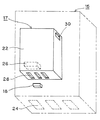
次に、第1制御装置15の構造について、図2に基づいて説明する。図2は、第1制御装置15の簡略化した下から見た斜視図である。
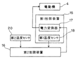
次に、エスカレータ100の電気的構成について図3に基づいて説明する。図3は、エスカレータ100のブロック図である。
次に、エスカレータ100の動作状態について図4のフローチャートに基づいて説明する。
本実施形態によれば、エスカレータ100を利用する乗客が増えて電力変換器17の発熱量が多くなると低速運転を行うため、温度上昇による誤作動防止のための出力停止動作を抑制し、連続運転を続けることができる。すなわち、電力変換器17内部の温度が上昇して内部保護による出力停止動作を行なう前に、エスカレータ100の速度を下げることにより、電力変換器17に対する負荷を下げて、出力停止動作を抑制する。
上記実施形態では、第1低速運転と第2低速運転(超低速運転)の2段階の連続運転としたが、これに限らず、例えば超低速運転に代えてエスカレータ100を停止させることで、超低速運転よりも早く低速運転可能な温度に電力変換器17内部の温度を下げることができる。
Claims (6)
- トラスの機械室内部に設けられた第1温度センサと、
前記機械室に配された制御装置に設けられた第2温度センサと、
(1)前記第1温度センサの検出温度が第1基準温度より高い場合、又は、前記第2温度センサの検出温度が第2基準温度より高い場合には、通常運転の通常速度v0より低速の第1低速度v1で第1低速運転を行い、(2)前記第1温度センサの前記検出温度が第1基準温度より高く、かつ、前記第2温度センサの前記検出温度が前記第2基準温度より高い場合には、0<=v2<v1<v0の関係を有する第2低速度v2で第2低速運転を行う主制御手段と、
を有する乗客コンベア。 - 前記第2温度センサは、乗降板の下部に設けられている、
請求項1に記載の乗客コンベア。 - 前記第1温度センサは、前記制御装置内の電力変換器に設けられている、
を有する請求項1又は2に記載の乗客コンベア。 - 前記第1温度センサは、前記電力変換器に設けられた冷却ファンの吸気口に設けられている、
請求項3に記載の乗客コンベア。 - 前記主制御手段は、前記第1温度センサの前記検出温度が前記第1基準温度より低くなり、かつ、前記第2温度センサの前記検出温度が前記第2基準温度より低くなると、前記通常速度v0の前記通常運転に復帰させる、
請求項1乃至4のいずれか一項に記載の乗客コンベア。 - 前記第2低速度v2が0である、
請求項1乃至5のいずれか一項に記載の乗客コンベア。
Priority Applications (1)
| Application Number | Priority Date | Filing Date | Title |
|---|---|---|---|
| JP2012134042A JP5420719B2 (ja) | 2012-06-13 | 2012-06-13 | 乗客コンベア |
Applications Claiming Priority (1)
| Application Number | Priority Date | Filing Date | Title |
|---|---|---|---|
| JP2012134042A JP5420719B2 (ja) | 2012-06-13 | 2012-06-13 | 乗客コンベア |
Publications (2)
| Publication Number | Publication Date |
|---|---|
| JP2013256369A JP2013256369A (ja) | 2013-12-26 |
| JP5420719B2 true JP5420719B2 (ja) | 2014-02-19 |
Family
ID=49953150
Family Applications (1)
| Application Number | Title | Priority Date | Filing Date |
|---|---|---|---|
| JP2012134042A Active JP5420719B2 (ja) | 2012-06-13 | 2012-06-13 | 乗客コンベア |
Country Status (1)
| Country | Link |
|---|---|
| JP (1) | JP5420719B2 (ja) |
Families Citing this family (3)
| Publication number | Priority date | Publication date | Assignee | Title |
|---|---|---|---|---|
| CN105174015A (zh) * | 2015-10-09 | 2015-12-23 | 康力电梯股份有限公司 | 一种温度监控装置 |
| JP6581252B1 (ja) * | 2018-06-27 | 2019-09-25 | 東芝エレベータ株式会社 | 乗客コンベア |
| WO2022003795A1 (ja) * | 2020-06-29 | 2022-01-06 | 三菱電機株式会社 | 乗客コンベア |
Family Cites Families (3)
| Publication number | Priority date | Publication date | Assignee | Title |
|---|---|---|---|---|
| JPH1121060A (ja) * | 1997-07-01 | 1999-01-26 | Hitachi Ltd | 寒冷地用乗客コンベアの運転制御装置 |
| JP3465219B2 (ja) * | 1997-12-22 | 2003-11-10 | 株式会社日立製作所 | 乗客コンベア |
| JP2008137752A (ja) * | 2006-11-30 | 2008-06-19 | Hitachi Building Systems Co Ltd | 乗客コンベアの制御方法 |
-
2012
- 2012-06-13 JP JP2012134042A patent/JP5420719B2/ja active Active
Also Published As
| Publication number | Publication date |
|---|---|
| JP2013256369A (ja) | 2013-12-26 |
Similar Documents
| Publication | Publication Date | Title |
|---|---|---|
| JP5420719B2 (ja) | 乗客コンベア | |
| JP2007153536A (ja) | 乗客コンベア装置 | |
| JP6454259B2 (ja) | 乗客コンベア及び乗客コンベアの制御方法 | |
| JP2006213447A (ja) | エレベーター装置 | |
| JP4597648B2 (ja) | エレベータ制御装置 | |
| JP4298389B2 (ja) | 速度切換え式乗客コンベア | |
| JP5791205B2 (ja) | 乗客コンベア | |
| JP6158393B1 (ja) | 乗客コンベアの電磁ブレーキ及びそれを用いた乗客コンベア | |
| JP5781184B1 (ja) | 乗客コンベア | |
| JP5920680B1 (ja) | 乗客コンベア | |
| JP2015051837A (ja) | 階間調整機能付きエレベータ | |
| JP5567101B2 (ja) | 乗客コンベア | |
| JP6988833B2 (ja) | 乗客コンベア | |
| JP2005029309A (ja) | 速度切換え式乗客コンベア | |
| JP5546566B2 (ja) | 乗客コンベア、及び、乗客コンベアの踏段の停止方法 | |
| JP2003341970A (ja) | コンベア装置 | |
| JP2015016952A (ja) | 乗客コンベア及び乗客コンベアの制御方法 | |
| JP2016050062A (ja) | 乗客コンベア | |
| WO2022003795A1 (ja) | 乗客コンベア | |
| JP6441439B1 (ja) | 乗客コンベア | |
| JP6260479B2 (ja) | 乗客コンベアの改造方法 | |
| JP7052898B1 (ja) | 乗客コンベアの安全装置 | |
| JP5210131B2 (ja) | 乗客コンベア装置 | |
| JP2015117112A (ja) | 乗客コンベア | |
| JP2019031384A (ja) | 乗客コンベア |
Legal Events
| Date | Code | Title | Description |
|---|---|---|---|
| A521 | Written amendment |
Free format text: JAPANESE INTERMEDIATE CODE: A523 Effective date: 20131003 |
|
| TRDD | Decision of grant or rejection written | ||
| A01 | Written decision to grant a patent or to grant a registration (utility model) |
Free format text: JAPANESE INTERMEDIATE CODE: A01 Effective date: 20131022 |
|
| A61 | First payment of annual fees (during grant procedure) |
Free format text: JAPANESE INTERMEDIATE CODE: A61 Effective date: 20131120 |
|
| R150 | Certificate of patent or registration of utility model |
Ref document number: 5420719 Country of ref document: JP Free format text: JAPANESE INTERMEDIATE CODE: R150 |
|
| S531 | Written request for registration of change of domicile |
Free format text: JAPANESE INTERMEDIATE CODE: R313531 |
|
| R350 | Written notification of registration of transfer |
Free format text: JAPANESE INTERMEDIATE CODE: R350 |