JP5372156B2 - Liquid crystal display device manufacturing apparatus and liquid crystal display device manufacturing method - Google Patents
Liquid crystal display device manufacturing apparatus and liquid crystal display device manufacturing method Download PDFInfo
- Publication number
- JP5372156B2 JP5372156B2 JP2011523536A JP2011523536A JP5372156B2 JP 5372156 B2 JP5372156 B2 JP 5372156B2 JP 2011523536 A JP2011523536 A JP 2011523536A JP 2011523536 A JP2011523536 A JP 2011523536A JP 5372156 B2 JP5372156 B2 JP 5372156B2
- Authority
- JP
- Japan
- Prior art keywords
- liquid crystal
- plate
- display device
- crystal display
- positioning pin
- Prior art date
- Legal status (The legal status is an assumption and is not a legal conclusion. Google has not performed a legal analysis and makes no representation as to the accuracy of the status listed.)
- Expired - Fee Related
Links
Images


Classifications
-
- G—PHYSICS
- G02—OPTICS
- G02F—OPTICAL DEVICES OR ARRANGEMENTS FOR THE CONTROL OF LIGHT BY MODIFICATION OF THE OPTICAL PROPERTIES OF THE MEDIA OF THE ELEMENTS INVOLVED THEREIN; NON-LINEAR OPTICS; FREQUENCY-CHANGING OF LIGHT; OPTICAL LOGIC ELEMENTS; OPTICAL ANALOGUE/DIGITAL CONVERTERS
- G02F1/00—Devices or arrangements for the control of the intensity, colour, phase, polarisation or direction of light arriving from an independent light source, e.g. switching, gating or modulating; Non-linear optics
- G02F1/01—Devices or arrangements for the control of the intensity, colour, phase, polarisation or direction of light arriving from an independent light source, e.g. switching, gating or modulating; Non-linear optics for the control of the intensity, phase, polarisation or colour
- G02F1/13—Devices or arrangements for the control of the intensity, colour, phase, polarisation or direction of light arriving from an independent light source, e.g. switching, gating or modulating; Non-linear optics for the control of the intensity, phase, polarisation or colour based on liquid crystals, e.g. single liquid crystal display cells
- G02F1/1303—Apparatus specially adapted to the manufacture of LCDs
-
- G—PHYSICS
- G02—OPTICS
- G02F—OPTICAL DEVICES OR ARRANGEMENTS FOR THE CONTROL OF LIGHT BY MODIFICATION OF THE OPTICAL PROPERTIES OF THE MEDIA OF THE ELEMENTS INVOLVED THEREIN; NON-LINEAR OPTICS; FREQUENCY-CHANGING OF LIGHT; OPTICAL LOGIC ELEMENTS; OPTICAL ANALOGUE/DIGITAL CONVERTERS
- G02F1/00—Devices or arrangements for the control of the intensity, colour, phase, polarisation or direction of light arriving from an independent light source, e.g. switching, gating or modulating; Non-linear optics
- G02F1/01—Devices or arrangements for the control of the intensity, colour, phase, polarisation or direction of light arriving from an independent light source, e.g. switching, gating or modulating; Non-linear optics for the control of the intensity, phase, polarisation or colour
- G02F1/13—Devices or arrangements for the control of the intensity, colour, phase, polarisation or direction of light arriving from an independent light source, e.g. switching, gating or modulating; Non-linear optics for the control of the intensity, phase, polarisation or colour based on liquid crystals, e.g. single liquid crystal display cells
- G02F1/133—Constructional arrangements; Operation of liquid crystal cells; Circuit arrangements
- G02F1/1333—Constructional arrangements; Manufacturing methods
- G02F1/133308—Support structures for LCD panels, e.g. frames or bezels
- G02F1/133325—Assembling processes
-
- G—PHYSICS
- G02—OPTICS
- G02F—OPTICAL DEVICES OR ARRANGEMENTS FOR THE CONTROL OF LIGHT BY MODIFICATION OF THE OPTICAL PROPERTIES OF THE MEDIA OF THE ELEMENTS INVOLVED THEREIN; NON-LINEAR OPTICS; FREQUENCY-CHANGING OF LIGHT; OPTICAL LOGIC ELEMENTS; OPTICAL ANALOGUE/DIGITAL CONVERTERS
- G02F2202/00—Materials and properties
- G02F2202/28—Adhesive materials or arrangements
-
- Y—GENERAL TAGGING OF NEW TECHNOLOGICAL DEVELOPMENTS; GENERAL TAGGING OF CROSS-SECTIONAL TECHNOLOGIES SPANNING OVER SEVERAL SECTIONS OF THE IPC; TECHNICAL SUBJECTS COVERED BY FORMER USPC CROSS-REFERENCE ART COLLECTIONS [XRACs] AND DIGESTS
- Y10—TECHNICAL SUBJECTS COVERED BY FORMER USPC
- Y10T—TECHNICAL SUBJECTS COVERED BY FORMER US CLASSIFICATION
- Y10T156/00—Adhesive bonding and miscellaneous chemical manufacture
- Y10T156/10—Methods of surface bonding and/or assembly therefor
-
- Y—GENERAL TAGGING OF NEW TECHNOLOGICAL DEVELOPMENTS; GENERAL TAGGING OF CROSS-SECTIONAL TECHNOLOGIES SPANNING OVER SEVERAL SECTIONS OF THE IPC; TECHNICAL SUBJECTS COVERED BY FORMER USPC CROSS-REFERENCE ART COLLECTIONS [XRACs] AND DIGESTS
- Y10—TECHNICAL SUBJECTS COVERED BY FORMER USPC
- Y10T—TECHNICAL SUBJECTS COVERED BY FORMER US CLASSIFICATION
- Y10T156/00—Adhesive bonding and miscellaneous chemical manufacture
- Y10T156/17—Surface bonding means and/or assemblymeans with work feeding or handling means
Abstract
Description
本発明は、液晶表示装置を構成する一対の板状体を貼り付ける、液晶表示装置の製造装置及び液晶表示装置の製造方法に関するものである。 The present invention relates to a liquid crystal display device manufacturing apparatus and a liquid crystal display device manufacturing method, in which a pair of plate-like bodies constituting a liquid crystal display device are attached.
従来より、液晶表示装置の製造方法として、例えば、特許文献1では、カセット内の液晶基板をロボットアームに載せて、プリアライメント領域に移送し、ロボットアームをY軸方向に移動して、二つのY位置センサを用いて液晶基板のX辺のX軸に対する傾斜角を求め、液晶基板を4本のチャックピンに載せかえて、回転台を時計方向に所定角度だけ回転し、ロボットアームで再び液晶基板を吸着して、回転台を反時計方向に所定角度だけ戻し、液晶基板のY方向の位置を定めてから、ロボット本体をレールに沿ってX軸方向に移動して、液晶基板のY辺がX位置センサで検出されるようにしてプリアライメントするものが知られている。
Conventionally, as a method for manufacturing a liquid crystal display device, for example, in
また、特許文献2では、原版とホログラム感材のガラス基板の寸法を一致させ、位置合わせ用の当てピンに当てて、あるいは枠にはめ込んで位置合わせし、あるいは原版とホログラム感材のガラス基板内に位置合わせ用のマーカーを形成し、両者のマーカーを一致させることにより位置合わせして複製している。
Also, in
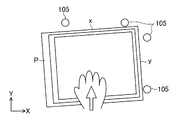
ところで、従来の液晶パネルとバックライトとをそれぞれ水平面に載置して貼り付ける工程においては、液晶パネルとバックライトとの厳密な貼付精度が要求される。この貼付精度管理位置は、液晶パネルの外形のX方向及びY方向とバックライトの外形におけるX方向及びY方向となっている。例えば、図10に示すように、液晶パネルPのX方向の一辺xとこれに垂直なY方向の他辺yとを位置決めピン105に目視により手で押さえ付けて水平にスライドさせながら位置決めする。このとき、感覚に頼ることが多く、位置決めが不十分になりやすいので、貼付精度管理位置にばらつきや傾きが生じることがある。
By the way, in the process of attaching and attaching a conventional liquid crystal panel and a backlight on a horizontal plane, strict sticking accuracy between the liquid crystal panel and the backlight is required. The pasting accuracy management positions are the X direction and Y direction of the outer shape of the liquid crystal panel and the X direction and Y direction of the outer shape of the backlight. For example, as shown in FIG. 10, one side x of the liquid crystal panel P in the X direction and the other side y in the Y direction perpendicular to the liquid crystal panel P are visually pressed against the
また、図11及び図12に示すように、シリンダー106等を用いて、位置決めピン105と反対側から液晶パネルPやバックライトBを強制的に押し付けて位置決めする場合には、その押付力が強すぎたり、位置決めスピードが速すぎたり、位置決めピン105の材質が固すぎたりすると、液晶パネルPやバックライトBの筐体にカケ、割れ等が発生して不良品となる場合がある。
Further, as shown in FIGS. 11 and 12, when the liquid crystal panel P and the backlight B are forcibly pressed and positioned from the side opposite to the
しかも、図12に示すように、バックライトBの筐体に剛性がなければ、歪みdが発生して貼付精度不良となるという問題があった。 In addition, as shown in FIG. 12, if the casing of the backlight B is not rigid, there is a problem that distortion d occurs, resulting in poor pasting accuracy.
本発明は、かかる点に鑑みてなされたものであり、その目的とするところは、簡単な方法で貼付対象物の位置決めを正確に行って精度のよい貼付を実現することにある。 This invention is made | formed in view of this point, The place made into the objective is to implement | achieve accurate sticking by accurately positioning a sticking target object with a simple method.
上記の目的を達成するために、この発明では、各貼付対象物における互いに対応する対角線が水平線に垂直な鉛直になるように各貼付対象物を保持するようにした。 In order to achieve the above object, in the present invention, each sticking object is held so that diagonal lines corresponding to each other in each sticking object are perpendicular to the horizontal line.
具体的には、第1の発明では、液晶表示装置を構成する第1板状体と第2板状体とを貼り合わせる液晶表示装置の製造装置を対象とする。 Specifically, the first invention is directed to an apparatus for manufacturing a liquid crystal display device in which a first plate-like body and a second plate-like body constituting a liquid crystal display device are bonded together.
そして、上記製造装置は、
上記第1板状体における一方の対角線が鉛直となるように該第1板状体の自重を利用して位置決めして保持する複数の第1位置決めピンを有する第1保持具と、
上記第2板状体における上記第1板状体の対角線に対応する対角線が鉛直となるように該第2板状体の自重を利用して位置決めして保持する複数の第2位置決めピンを有する第2保持具と、
上記第1保持具及び上記第2保持具の少なくとも一方を水平移動させて該第1保持具及び第2保持具を相対的に近付ける貼付機構と、
を備えている。And the manufacturing apparatus is
A first holding tool having a plurality of first positioning pins that are positioned and held by utilizing the weight of the first plate-like body so that one diagonal line in the first plate-like body is vertical;
A plurality of second positioning pins that are positioned and held by utilizing the weight of the second plate-like body so that the diagonal line corresponding to the diagonal line of the first plate-like body in the second plate-like body is vertical. A second holder;
An affixing mechanism for moving at least one of the first holding tool and the second holding tool horizontally to relatively move the first holding tool and the second holding tool;
It has.
上記の構成によると、各板状体をそれぞれの自重を用いてスライドさせながら外形面を位置決めピンに当接させて位置決めするので、必要以上に位置決めピンが各板状体を押さえ付けて傷付けることはない。そして、正確に位置決めされた各板状体を互いに近付けることで高い精度で貼付が行われる。なお、鉛直とは、水平線に垂直な重力のかかる方向を意味する。 According to the above configuration, the outer surface is brought into contact with the positioning pin while sliding each plate-like body using its own weight, so that the positioning pin presses and damages the plate-like body more than necessary. There is no. Then, sticking is performed with high accuracy by bringing the accurately positioned plate-like bodies closer to each other. Note that the vertical means a direction in which gravity is applied perpendicular to the horizon.
第2の発明では、第1の発明において、
上記複数の第1位置決めピンは、上記第1板状体のX方向の第1辺に当接するX方向に並んだものと、該第1板状体のY方向の第2辺に当接するY方向に並んだものとからなり、
上記複数の第2位置決めピンは、上記第2板状体のX方向の第1辺に当接するX方向に並んだものと、該第2板状体のY方向の第2辺に当接するY方向に並んだものとからなる。In the second invention, in the first invention,
The plurality of first positioning pins are arranged in the X direction that contacts the first side in the X direction of the first plate-like body, and Y that contacts the second side in the Y direction of the first plate-like body. Consisting of things lined up in the direction,
The plurality of second positioning pins are arranged in the X direction in contact with the first side in the X direction of the second plate-like body and Y in contact with the second side in the Y direction of the second plate-like body. It consists of things lined up in the direction.
上記の構成によると、第1板状体の第1辺及び第2辺のいずれか一方を、対応するX方向又はY方向に並んだ第1位置決めピンに当接させた状態で、この第1位置決めピンに沿って第1板状体を滑らせながら、上記第1板状体の第1辺及び第2辺のいずれか他方を、他方の第1位置決めピンに当接させて位置決めすることができる。同様に第2板状体の第1辺及び第2辺のいずれか一方を、対応するX方向又はY方向に並んだ第2位置決めピンに当接させた状態で、この第2位置決めピンに沿って第2板状体を滑らせながら、上記第2板状体の第1辺及び第2辺のいずれか他方を、他方の第2位置決めピンに当接させて位置決めすることができる。 According to the above configuration, the first plate-like body has the first side or the second side in contact with the first positioning pins arranged in the corresponding X direction or Y direction. While the first plate-like body is slid along the positioning pin, the other one of the first side and the second side of the first plate-like body is brought into contact with the other first positioning pin for positioning. it can. Similarly, either one of the first side and the second side of the second plate-like body is in contact with the second positioning pin arranged in the corresponding X direction or Y direction, and along the second positioning pin. Then, while sliding the second plate-like body, either one of the first side and the second side of the second plate-like body can be brought into contact with the other second positioning pin and positioned.
第3の発明では、第1又は第2の発明において、
上記第1保持具及び上記第2保持具の少なくとも一方は、水平移動、鉛直移動及び角度調整可能に構成されている。In the third invention, in the first or second invention,
At least one of the first holder and the second holder is configured to be capable of horizontal movement, vertical movement, and angle adjustment.
上記の構成によると、第1板状体及び第2板状体間のX方向、Y方向又は角度の微小なずれを補正して正確に貼付を行うことができる。 According to said structure, it can paste | paste correctly, correct | amending the small shift | offset | difference of the X direction between the 1st plate-shaped body and the 2nd plate-shaped body, a Y direction, or an angle.
第4の発明では、第1乃至第3のいずれか1つの発明において、
上記第1保持具は上記第1板状体を吸着及び解放させる第1吸着機構を備え、
上記第2保持具は上記第2板状体を吸着及び解放させる第2吸着機構を備えている。In a fourth invention, in any one of the first to third inventions,
The first holder includes a first suction mechanism for sucking and releasing the first plate-like body,
The second holder includes a second suction mechanism for sucking and releasing the second plate-like body.
上記の構成によると、第1位置決めピンと第2位置決めピンとが干渉するおそれのある場合に、いずれかの位置決めピンを回避させても正確に位置決めされた状態のまま各板状体を保持することができ、また、貼付後には解放することができる。 According to said structure, when there exists a possibility that a 1st positioning pin and a 2nd positioning pin may interfere, even if it avoids any positioning pin, it can hold | maintain each plate-shaped body with the state positioned correctly. It can be released after sticking.
第5の発明では、第4の発明において、
上記第1位置決めピン及び第2位置決めピンの少なくとも一方は、他方の位置決めピンとの接触を避けるための回避機構に設けられ、
上記回避機構は、
位置決めピン回避用シリンダーと、
該位置決めピン回避用シリンダーにスライド移動されるスライド部材とを備え、
上記スライド部材に上記第1位置決めピン又は第2位置決めピンが設けられている。In the fifth invention, in the fourth invention,
At least one of the first positioning pin and the second positioning pin is provided in an avoidance mechanism for avoiding contact with the other positioning pin;
The avoidance mechanism is
A positioning pin avoiding cylinder;
A slide member that is slid and moved to the positioning pin avoiding cylinder,
The slide member is provided with the first positioning pin or the second positioning pin.
上記の構成によると、第1吸着機構及び第2吸着機構の少なくとも一方を作動させた状態で、位置決めピン回避用シリンダーを伸縮させてスライド部材をスライド移動させて第1位置決めピン及び第2位置決めピンの少なくとも一方を回避させても、第1吸着機構が第1板状体を吸着し、第2吸着機構が第2板状体を吸着しているので、第1板状体と第2板状体とが位置ずれすることなく、その位置ずれしない状態で、第1位置決めピン及び第2位置決めピンが接触するのが防止される。 According to the above configuration, in a state where at least one of the first suction mechanism and the second suction mechanism is operated, the positioning pin avoiding cylinder is expanded and contracted to slide the slide member, and the first positioning pin and the second positioning pin. Even if at least one of them is avoided, the first adsorption mechanism adsorbs the first plate-like body and the second adsorption mechanism adsorbs the second plate-like body. The first positioning pin and the second positioning pin are prevented from coming into contact with each other without being displaced with respect to the body.
第6の発明では、第1乃至第5のいずれか1つの発明において、
上記貼付機構は、エアーシリンダーとレギュレータとタイマーとを備えている。In a sixth invention, in any one of the first to fifth inventions,
The sticking mechanism includes an air cylinder, a regulator, and a timer.
上記の構成によると、レギュレータとタイマーとでエアーシリンダーを制御して適度な力と時間とで第1板状体と第2板状体とを適切に貼り合わせることができる。 According to said structure, an air cylinder can be controlled with a regulator and a timer, and a 1st plate-shaped body and a 2nd plate-shaped body can be bonded together appropriately by moderate force and time.
第7の発明では、第1乃至第6のいずれか1つの発明において、
上記第1位置決めピン及び第2位置決めピンは、それぞれ
金属製のピン本体と、
該ピン本体を覆う樹脂製カラーとを備えている。In a seventh invention, in any one of the first to sixth inventions,
The first positioning pin and the second positioning pin are respectively a metal pin body,
And a resin collar covering the pin body.
上記の構成によると、各位置決めピンの樹脂製カラーが第1板状体又は第2板状体に当接するので、第1板状体と第2板状体に傷が付きにくい。 According to said structure, since the resin-made collars of each positioning pin contact | abut to a 1st plate-shaped body or a 2nd plate-shaped body, a 1st plate-shaped body and a 2nd plate-shaped body are hard to be damaged.
第8の発明では、第1乃至第7のいずれか1つの発明において、
上記第1板状体は、液晶パネルであり、
上記第2板状体は、バックライトである。In an eighth invention, in any one of the first to seventh inventions,
The first plate-like body is a liquid crystal panel,
The second plate-like body is a backlight.
上記の構成によると、バックライトを高い精度で傷を付けることなく液晶パネルに貼り付けることができる。 According to said structure, a backlight can be affixed on a liquid crystal panel with a high precision, without scratching.
第9の発明では、第1乃至第7のいずれか1つの発明において、
上記第1板状体は、タッチパネルであり、
上記第2板状体は、液晶パネル及びバックライトを含む液晶モジュールである。In a ninth invention, in any one of the first to seventh inventions,
The first plate-like body is a touch panel,
The second plate-like body is a liquid crystal module including a liquid crystal panel and a backlight.
上記の構成によると、液晶パネルとバックライトとを貼り付けた液晶モジュールにタッチパネルを高い精度で傷を付けることなく貼り付けることができる。 According to said structure, a touch panel can be affixed on a liquid crystal module which affixed the liquid crystal panel and the backlight with high precision, without scratching.
第10の発明では、液晶表示装置を構成する第1板状体と第2板状体とを貼り合わせる液晶表示装置の製造方法を対象とし、
上記製造方法は、
複数の第1位置決めピンを有する第1保持具と、複数の第2位置決めピンを有する第2保持具とを備えた製造装置を用意し、
上記第1位置決めピン上に上記第1板状体における一方の対角線が鉛直となるように該第1板状体の外形面を当接させて位置決めした状態で保持し、
上記第2位置決めピン上に上記第2板状体における上記第1板状体の対角線に対応する対角線が鉛直となるように該第2板状体の外形面を当接させて位置決めした状態で保持し、
上記第1保持具と上記第2保持具とを相対的に近付けて上記第1板状体と上記第2板状体とを貼り合わせる構成とする。The tenth invention is directed to a method for manufacturing a liquid crystal display device in which a first plate and a second plate constituting a liquid crystal display are bonded,
The above manufacturing method is
Preparing a manufacturing apparatus comprising a first holder having a plurality of first positioning pins and a second holder having a plurality of second positioning pins;
Hold the outer surface of the first plate-like body in contact with the first positioning pin so that one diagonal line of the first plate-like body is vertical on the first positioning pin;
In a state where the outer surface of the second plate-shaped body is in contact with and positioned on the second positioning pin so that the diagonal line corresponding to the diagonal line of the first plate-shaped body in the second plate-shaped body is vertical. Hold and
The first holding tool and the second holding tool are relatively brought close to each other and the first plate and the second plate are bonded together.
上記の構成によると、各位置決めピン上に各板状体における一方の対角線が鉛直となるように、自重を利用して各板状体の外形面を当接させて位置決めするので、必要以上に位置決めピンが各板状体を押さえ付けて傷付けることはない。そして、正確に位置決めされた各板状体を相対的に近付けることで高い精度で貼付が行われる。 According to the above configuration, the outer surface of each plate-like body is contacted and positioned using its own weight so that one diagonal line of each plate-like body is vertical on each positioning pin. The positioning pin does not damage each plate-like body. And it sticks with high precision by relatively approaching each plate-shaped body positioned correctly.
第11の発明では、第10の発明において、
上記第1板状体の第1辺及び第2辺のいずれか一方を、X方向及びY方向のいずれか一方に並んだ上記第1位置決めピンに当接させた状態で該第1位置決めピンに沿って該第1板状体を滑らせながら、上記第1板状体の第1辺及び第2辺のいずれか他方を、X方向及びY方向の他方に並んだ第1位置決めピンに当接させて該第1板状体を位置決めし、
上記第2板状体の第1辺及び第2辺のいずれか一方を、X方向及びY方向のいずれか一方に並んだ上記第2位置決めピンに当接させた状態で該第2位置決めピンに沿って該第2板状体を滑らせながら、上記第2板状体の第1辺及び第2辺のいずれか他方を、X方向及びY方向の他方に並んだ第2位置決めピンに当接させて該第2板状体を位置決めする構成とする。
In an eleventh aspect, in the tenth aspect,
Either one of the first side and the second side of the first plate-like body is in contact with the first positioning pin arranged in either the X direction or the Y direction. While sliding the first plate-like body along, contact one of the first side and the second side of the first plate-like body with the first positioning pin arranged in the other of the X direction and the Y direction. And positioning the first plate-like body,
Either one of the first side and the second side of the second plate-like body is brought into contact with the second positioning pin arranged in either the X direction or the Y direction. While sliding the second plate-like body along, contact one of the first side and the second side of the second plate-like body with the second positioning pin arranged in the other of the X direction and the Y direction. In this way, the second plate-like body is positioned.
上記の構成によると、第1板状体及び第2板状体の自重を利用して位置決めが滑らかかつ正確に行え、必要以上に力を加えなくてもよいので、第1板状体及び第2板状体が傷付かない。 According to the above configuration, the first plate and the second plate can be positioned smoothly and accurately using their own weights, and it is not necessary to apply more force than necessary. 2 The plate is not damaged.
以上説明したように、本発明によれば、自重を利用して第1板状体と第2板状体とをそれぞれ位置決めして貼り付けるようにしたことにより、簡単な方法で貼付対象物の位置決めを正確に行って精度のよい貼付を実現することができる。 As described above, according to the present invention, the first plate-like body and the second plate-like body are positioned and pasted using their own weights, so that the object to be pasted can be obtained by a simple method. Accurate sticking can be realized by accurately positioning.
以下、本発明の実施形態を図面に基づいて説明する。 Hereinafter, embodiments of the present invention will be described with reference to the drawings.
−液晶表示装置の製造装置の構成−
図1〜図3は本発明の実施形態の液晶表示装置の製造装置1を示し、例えば、液晶表示装置(図示せず)を構成する第1板状体としての液晶パネルPと第2板状体としてのバックライトBとを貼り合わせるのに使用される。-Configuration of liquid crystal display manufacturing equipment-
1 to 3 show an
製造装置1は、床等に固定される固定台1aを備え、この固定台1aに支持台1bが回動可能に支持されている。具体的には、製造装置1は、対角線鉛直位置調整機構2を備え、固定台1aの下部両側面に形成した円弧状ガイド溝2a内に支持台1bの回動レバー2bが配置され、この回動レバー2bを操作することで、回動レバー2bがガイド溝2a内を移動し、それに伴って、支持台1bが固定台1aに対して回動するようになっている。
The
支持台1b上には、相対的に水平方向に変位可能な第1保持具3及び第2保持具4が設けられている。
A
具体的には、第1保持具3は、液晶パネルPが吸着される第1保持板3aを備えている。この第1保持板3aは、液晶パネルPの2本の対角線のうち、長い方の対角線Cが水平線と垂直な重力方向である鉛直となるように、予め図3のように斜めに傾けられて設置されている。この第1保持板3a(厳密には後述する回避機構7)から複数の(本実施形態では、4本の)第1位置決めピン5が突出している。図3に示すように、各第1位置決めピン5は、金属製の中実又は中空のピン本体5aと、このピン本体5aを覆う樹脂製カラー5bとを備えている。樹脂製カラー5bは、液晶パネルPを傷付けないように、できるだけ柔らかい材質が選択されている。この第1位置決めピン5は、第2位置決めピン6との接触を避けるための回避機構7に設けられている。つまり、回避機構7は、位置決めピン回避用シリンダー8と、この位置決めピン回避用シリンダー8にスライド移動されるスライド部材9とを備えている。図9にも示すように、スライド部材9は、平面視L字形状のもので、上下に延びるレール9aに嵌合され、上下にスライド移動可能となっている。このスライド部材9に4本の第1位置決めピン5が、液晶パネルPのX方向の第1辺xとこれに垂直なY方向の第2辺yとを支えるように配置されている。例えば、図3に示すように、2本の第1位置決めピン5が、第1保持板3aのX方向に沿って配置され、残り2本の第1位置決めピン5がY方向に沿って配置されている。このことで、第1位置決めピン5が、液晶パネルPの対角線Cが鉛直となるように、液晶パネルPの自重を利用して位置決めして保持するようになっている。
Specifically, the
また、第1保持具3は液晶パネルPを吸着及び解放させる第1吸着機構10を備えている。図2、図4等に示すように、第1吸着機構10は、真空ポンプなどの真空吸着機器11に接続される吸着用エアーチューブ10aと、第1保持板3aに形成された複数(本実施形態では9つ)の真空吸着穴10bとを備え、この真空吸着穴10bと吸着用エアーチューブ10aとが第1保持板3a内で連通している。このことで、真空吸着機器11を作動させて吸着用エアーチューブ10aから空気を吸い込むことで、液晶パネルPが第1保持板3a上で吸着され、真空吸着機器11を停止することで液晶パネルPを解放できるようになっている。
Further, the
さらに、第1保持具3は、水平移動、鉛直移動及び角度調整可能に構成する微調整機構3cを備え、この微調整機構3cにより、液晶パネルPの位置を微調整可能となっている。詳細は図示しないが、第1保持板3a及びスライド部材9は、支持台1bに固定された第1保持具3の第1支持部3bに対して水平移動、鉛直移動及び角度調整可能に支持され、第1支持部3bに設けた3つのツマミ12(図3及び図4にのみ示す)をそれぞれ操作すれば、スライド部材9が水平移動、鉛直移動又は回動し、第2保持具4に保持されたバックライトBに対して位置が微調整されるようになっている。なお、第2保持具4を水平移動、鉛直移動及び角度調整可能に構成してもよいし、第1保持具3と第2保持具4との両方を水平移動、鉛直移動及び角度調整可能に構成してもよい。
Further, the
一方、第2保持具4も同様にバックライトBを保持する第2保持板4aに複数の第2位置決めピン6を有している。この第2位置決めピン6は、バックライトBの2本の対角線のうち液晶パネルPの対角線Cに対応する、長い方の対角線が鉛直となるように、このバックライトBの自重を利用して位置決めして保持するように設けられている。例えば、4本の第2位置決めピン6が、バックライトBのX方向の第1辺とこれに垂直なY方向の第2辺とを支えるように、2本の第2位置決めピン6がX方向に沿って配置され、残り2本の第2位置決めピン6がY方向に沿って配置されている。第2位置決めピン6も、金属製の中実又は中空のピン本体6aと、このピン本体6aを覆う樹脂製カラー6bとを備えている。なお、第2位置決めピン6も、第1位置決めピン5と同様に回避機構7に設けてもよく、逆に第2保持具4側にのみ回避機構7を設けてもよい。
On the other hand, the
図1に示すように、第2保持具4は、貼付機構13によって水平移動可能に構成され、第1保持具3に対して水平方向に位置調整可能となっている。貼付機構13は、エアーシリンダー13aとレギュレータ13bとタイマー13cとを備えている。例えば、レギュレータ13bにより、加圧力を0〜約120Nまで調整することができ、通常は30±5Nに設定されている。また、タイマー13cを利用することで、例えば、貼付時間を10秒まで設定可能で、通常2±0.5秒に設定されている。なお、第1保持具3側のみを水平移動可能に構成したり、第1保持具3と第2保持具4との両方を水平移動可能に構成してもよい。
As shown in FIG. 1, the
図5に示すように、バックライトBの周縁に矩形枠状の両面テープTが貼り付けられている。この両面テープTにより、液晶パネルPを適度な圧力で押さえ付けると、バックライトBに液晶パネルPが貼り付けられるようになっている。両面テープTは、中央が切り欠かれて液晶パネルPの表示領域を狭めないようになっている。 As shown in FIG. 5, a rectangular frame-shaped double-sided tape T is attached to the periphery of the backlight B. When the liquid crystal panel P is pressed with an appropriate pressure by the double-sided tape T, the liquid crystal panel P is attached to the backlight B. The double-sided tape T is cut out at the center so that the display area of the liquid crystal panel P is not narrowed.
第2保持具4も、バックライトBを吸着及び解放させる第2吸着機構14を備えている。詳しくは図示しないが、この第2吸着機構14も、真空吸着機器11に接続される吸着用エアーチューブ14aと、第2保持板4aに形成された複数の真空吸着穴とを備え、この真空吸着穴と吸着用エアーチューブ14aとが第2保持板4a内で連通している。
The
−液晶表示装置の製造方法−
次に、本実施形態にかかる液晶表示装置の製造方法について説明する。具体的には、液晶表示装置を構成する液晶パネルPとバックライトBとを貼り合わせる液晶表示装置の製造方法について説明する。-Manufacturing method of liquid crystal display device-
Next, a method for manufacturing the liquid crystal display device according to the present embodiment will be described. Specifically, a method for manufacturing a liquid crystal display device in which the liquid crystal panel P and the backlight B constituting the liquid crystal display device are bonded together will be described.
まず、複数の第1位置決めピン5を有する第1保持具3と、複数の第2位置決めピン6を有する第2保持具4とを備えた製造装置1を用意し、第1位置決めピン5で液晶パネルPの対角線Cが鉛直となるように、かつ第2位置決めピン6でバックライトBの長い方の対角線が鉛直となるように、回動レバー2bを操作して支持台1bを固定台1aに対して回動させておく。
First, a
次いで、第1位置決めピン5上に液晶パネルPの対角線Cが鉛直となるように該液晶パネルPの外形面を当接させて位置決めした状態で保持する。
Next, the outer peripheral surface of the liquid crystal panel P is brought into contact with the
具体的には、まず、図6に示すように、液晶パネルPを上方からゆっくりと第1保持板3aに沿わせながら第1位置決めピン5の方へ移動させる。
Specifically, first, as shown in FIG. 6, the liquid crystal panel P is moved from the upper side toward the first positioning pins 5 while slowly being along the
図7(a)に示すように、最初に液晶パネルPの第1辺xをX方向に並ぶ第1位置決めピン5に沿わせ、手を離す。すると、液晶パネルPの自重でX方向に並ぶ第1位置決めピン5に沿って滑りながら、第2辺yがY方向に並ぶ第1位置決めピン5に当接し、位置決めされる。又は、図7(b)に示すように、最初に液晶パネルPの第2辺yをY方向に並ぶ第1位置決めピン5に沿わせ手を離す。すると、液晶パネルPの自重でY方向に並ぶ第1位置決めピン5に沿って滑りながら、第1辺xがX方向に並ぶ第1位置決めピン5に当接し、位置決めされる。これにより、図8に示すように、液晶パネルPの角部が4本の第1位置決めピン5に正確に位置決めされる。このとき、第1位置決めピン5の樹脂製カラー5bが液晶パネルPに当接するので、液晶パネルPに傷が付きにくい。
As shown in FIG. 7A, first, the first side x of the liquid crystal panel P is placed along the first positioning pins 5 arranged in the X direction, and the hands are released. Then, while sliding along the first positioning pins 5 arranged in the X direction by the weight of the liquid crystal panel P, the second side y comes into contact with the first positioning pins 5 arranged in the Y direction and is positioned. Alternatively, as shown in FIG. 7B, first, the second side y of the liquid crystal panel P is aligned with the first positioning pins 5 arranged in the Y direction, and the hand is released. Then, while sliding along the first positioning pins 5 arranged in the Y direction by the weight of the liquid crystal panel P, the first side x comes into contact with the first positioning pins 5 arranged in the X direction and is positioned. Thereby, as shown in FIG. 8, the corners of the liquid crystal panel P are accurately positioned on the four first positioning pins 5. At this time, since the
次いで、同様にバックライトBの第1辺及び第2辺を第2位置決めピン6に順次当接させて位置決めし、第2位置決めピン6上にバックライトBの長い方の対角線が鉛直となるように、保持する。バックライトBも液晶パネルPと同様に自重を利用して第2位置決めピン6で位置決めする。このときも、第2位置決めピン6の樹脂製カラー6bがバックライトBに当接するので、バックライトBに傷が付きにくい。
Next, similarly, the first side and the second side of the backlight B are sequentially brought into contact with the second positioning pins 6 for positioning, and the longer diagonal line of the backlight B is vertical on the second positioning pins 6. Hold on. Similarly to the liquid crystal panel P, the backlight B is positioned by the second positioning pins 6 using its own weight. Also at this time, since the resin collar 6b of the
次いで、真空吸着機器11を作動させて吸着用エアーチューブ10aから空気を吸い込むことで、液晶パネルPを第1保持板3a上に吸着させる。また、第2保持板4a側でも吸着用エアーチューブ14aから空気を吸い込み、バックライトBを第2保持板4a上に吸着させる。
Next, the
そして、液晶パネルPをバックライトBの貼付位置に対して微調整する必要であれば、ツマミ12を操作して、水平移動又は鉛直移動させ、さらに必要であれば角度調整させる。このことで、液晶パネルPのバックライトBに対する微小なずれが補正される。
Then, if it is necessary to finely adjust the liquid crystal panel P with respect to the attachment position of the backlight B, the
このように、液晶パネルPとバックライトBとをそれぞれの自重を用いてスライドさせながら外形面(第1辺x及び第2辺y)を第1又は第2位置決めピン5,6に当接させて位置決めするので、必要以上に第1又は第2位置決めピン5,6が液晶パネルP又はバックライトBを押さえ付けて割れやカケなどの傷を付けることはない。 In this way, the external surfaces (first side x and second side y) are brought into contact with the first or second positioning pins 5 and 6 while sliding the liquid crystal panel P and the backlight B using their own weights. Therefore, the first or second positioning pins 5 and 6 do not press the liquid crystal panel P or the backlight B more than necessary and cause damage such as cracks or chipping.
次いで、第1保持具3と第2保持具4とを相対的に近付けて液晶パネルPとバックライトBとを貼り合わせる。
Then, the liquid crystal panel P and the backlight B are bonded together by relatively bringing the
具体的には、そのままの状態で第2保持具4を水平移動させると、第1位置決めピン5と第2位置決めピン6とが干渉する可能性がある。このため、図9に示すように、位置決めピン回避用シリンダー8を駆動してスライド部材9を下方へスライドさせて第1位置決めピン5を回避させる。このように、第1位置決めピン5と第2位置決めピン6とが干渉するおそれのある場合に、第1位置決めピン5を回避させても、第1吸着機構10により液晶パネルPが吸引されているので、正確に位置決めされた状態のまま液晶パネルPを保持することができ、液晶パネルPがずれることはない。
Specifically, if the
その後、レギュレータ13bでエアーシリンダー13aが押す力を例えば30Nに調整してエアーシリンダー13aを伸長させ、液晶パネルPとバックライトBとが当接すると、タイマー13cがスタートして2秒間押さえ付ける。このようにレギュレータ13bで加圧力が大きくならないようにすることで、液晶パネルPとバックライトBとが損傷するのを防ぎ、タイマー13cで適度な時間押さえ付けて両面テープTをしっかりと密着させている。
Thereafter, the force pressed by the
最後に、真空吸着機器11を停止させ、液晶パネルPとバックライトBとが貼り付けられた液晶モジュールを取り出す。
Finally, the
したがって、本実施形態によると、自重を利用して液晶パネルPとバックライトBとをそれぞれ位置決めして貼り付けるようにしたことにより、簡単な方法で液晶パネルPとバックライトBとの位置決めを正確に行って精度のよい貼付を実現することができる。 Therefore, according to the present embodiment, the liquid crystal panel P and the backlight B are positioned and pasted by using their own weights, so that the liquid crystal panel P and the backlight B can be accurately positioned by a simple method. It is possible to achieve accurate pasting.
(その他の実施形態)
本発明は、実施形態について、以下のような構成としてもよい。(Other embodiments)
The present invention may have the following configurations for the embodiments.
すなわち、上記実施形態では、第1板状体は、液晶パネルPとし、第2板状体は、バックライトBとしたが、図1及び図2にのみかっこ書きで示すように、第1板状体をタッチパネルTとし、第2板状体を液晶パネルPとバックライトBとが貼り付けられた液晶モジュールMとしてもよい。上記説明した液晶表示装置の製造方法に引き続いて同様の工程で、タッチパネルTと液晶モジュールMとを貼り付けることができる。それにより、液晶モジュールにタッチパネルを高い精度で傷を付けることなく貼り付けることができる。 That is, in the above embodiment, the first plate-like body is the liquid crystal panel P and the second plate-like body is the backlight B. However, as shown in parentheses only in FIG. 1 and FIG. The state body may be the touch panel T, and the second plate body may be the liquid crystal module M to which the liquid crystal panel P and the backlight B are attached. The touch panel T and the liquid crystal module M can be attached in the same process following the manufacturing method of the liquid crystal display device described above. Thereby, a touch panel can be affixed on a liquid crystal module with high accuracy without scratching.
なお、以上の実施形態は、本質的に好ましい例示であって、本発明、その適用物や用途の範囲を制限することを意図するものではない。 In addition, the above embodiment is an essentially preferable illustration, Comprising: It does not intend restrict | limiting the range of this invention, its application thing, or a use.
以上説明したように、本発明は、一対の板状体を貼り付ける、液晶表示装置の製造装置及び液晶表示装置の製造方法について有用である。 As described above, the present invention is useful for a liquid crystal display device manufacturing apparatus and a liquid crystal display device manufacturing method in which a pair of plate-like bodies are attached.
1 液晶表示装置の製造装置
3 第1保持具
3c 微調整機構
4 第2保持具
5 第1位置決めピン
5a ピン本体
5b 樹脂製カラー
6 第2位置決めピン
6a ピン本体
6b 樹脂製カラー
7 回避機構
8 位置決めピン回避用シリンダー
9 スライド部材
10 第1吸着機構
10a 吸着用エアーチューブ
10b 真空吸着穴
11 真空吸着機器
13 貼付機構
13a エアーシリンダー
13b レギュレータ
13c タイマー
14 第2吸着機構
P 液晶パネル(第1板状体)
B バックライト(第2板状体)
C 対角線(一方の対角線)
T タッチパネル
M 液晶モジュール
x 第1辺
y 第2辺DESCRIPTION OF
B Backlight (second plate)
C diagonal line (one diagonal line)
T touch panel M liquid crystal module x first side y second side
Claims (11)
上記第1板状体における一方の対角線が鉛直となるように該第1板状体の自重を利用して位置決めして保持する複数の第1位置決めピンを有する第1保持具と、
上記第2板状体における上記第1板状体の対角線に対応する対角線が鉛直となるように該第2板状体の自重を利用して位置決めして保持する複数の第2位置決めピンを有する第2保持具と、
上記第1保持具及び上記第2保持具の少なくとも一方を水平移動させて該第1保持具及び第2保持具を相対的に近付ける貼付機構と、
を備えている
ことを特徴とする液晶表示装置の製造装置。In a manufacturing apparatus for a liquid crystal display device in which a first plate-like body and a second plate-like body constituting a liquid crystal display device are bonded together,
A first holding tool having a plurality of first positioning pins that are positioned and held by utilizing the weight of the first plate-like body so that one diagonal line in the first plate-like body is vertical;
A plurality of second positioning pins that are positioned and held by utilizing the weight of the second plate-like body so that the diagonal line corresponding to the diagonal line of the first plate-like body in the second plate-like body is vertical. A second holder;
An affixing mechanism for moving at least one of the first holding tool and the second holding tool horizontally to relatively move the first holding tool and the second holding tool;
An apparatus for manufacturing a liquid crystal display device, comprising:
上記複数の第1位置決めピンは、上記第1板状体のX方向の第1辺に当接するX方向に並んだものと、該第1板状体のY方向の第2辺に当接するY方向に並んだものとからなり、
上記複数の第2位置決めピンは、上記第2板状体のX方向の第1辺に当接するX方向に並んだものと、該第2板状体のY方向の第2辺に当接するY方向に並んだものとからなる
ことを特徴とする液晶表示装置の製造装置。In the manufacturing apparatus of the liquid crystal display device of Claim 1,
The plurality of first positioning pins are arranged in the X direction that contacts the first side in the X direction of the first plate-like body, and Y that contacts the second side in the Y direction of the first plate-like body. Consisting of things lined up in the direction,
The plurality of second positioning pins are arranged in the X direction in contact with the first side in the X direction of the second plate-like body and Y in contact with the second side in the Y direction of the second plate-like body. An apparatus for manufacturing a liquid crystal display device, comprising:
上記第1保持具及び上記第2保持具の少なくとも一方は、水平移動、鉛直移動及び角度調整可能に構成されている
ことを特徴とする液晶表示装置の製造装置。In the manufacturing apparatus of the liquid crystal display device according to claim 1 or 2,
An apparatus for manufacturing a liquid crystal display device, wherein at least one of the first holder and the second holder is configured to be capable of horizontal movement, vertical movement, and angle adjustment.
上記第1保持具は上記第1板状体を吸着及び解放させる第1吸着機構を備え、
上記第2保持具は上記第2板状体を吸着及び解放させる第2吸着機構を備えている
ことを特徴とする液晶表示装置の製造装置。In the manufacturing apparatus of the liquid crystal display device as described in any one of Claims 1 thru | or 3,
The first holder includes a first suction mechanism for sucking and releasing the first plate-like body,
The apparatus for manufacturing a liquid crystal display device, wherein the second holder includes a second suction mechanism for sucking and releasing the second plate-like body.
上記第1位置決めピン及び第2位置決めピンの少なくとも一方は、他方の位置決めピンとの接触を避けるための回避機構に設けられ、
上記回避機構は、
位置決めピン回避用シリンダーと、
該位置決めピン回避用シリンダーにスライド移動されるスライド部材とを備え、
上記スライド部材に上記第1位置決めピン又は第2位置決めピンが設けられている
ことを特徴とする液晶表示装置の製造装置。In the manufacturing apparatus of the liquid crystal display device of Claim 4,
At least one of the first positioning pin and the second positioning pin is provided in an avoidance mechanism for avoiding contact with the other positioning pin;
The avoidance mechanism is
A positioning pin avoiding cylinder;
A slide member that is slid and moved to the positioning pin avoiding cylinder,
An apparatus for manufacturing a liquid crystal display device, wherein the slide member is provided with the first positioning pin or the second positioning pin.
上記貼付機構は、エアーシリンダーとレギュレータとタイマーとを備えている
ことを特徴とする液晶表示装置の製造装置。In the manufacturing apparatus of the liquid crystal display device as described in any one of Claims 1 thru | or 5,
The said sticking mechanism is provided with the air cylinder, the regulator, and the timer, The manufacturing apparatus of the liquid crystal display device characterized by the above-mentioned.
上記第1位置決めピン及び第2位置決めピンは、それぞれ
金属製のピン本体と、
該ピン本体を覆う樹脂製カラーとを備えている
ことを特徴とする液晶表示装置の製造装置。In the manufacturing apparatus of the liquid crystal display device according to any one of claims 1 to 6,
The first positioning pin and the second positioning pin are respectively a metal pin body,
An apparatus for manufacturing a liquid crystal display device, comprising: a resin collar that covers the pin body.
上記第1板状体は、液晶パネルであり、
上記第2板状体は、バックライトである
ことを特徴とする液晶表示装置の製造装置。In the manufacturing apparatus of the liquid crystal display device as described in any one of Claims 1 thru | or 7,
The first plate-like body is a liquid crystal panel,
The apparatus for manufacturing a liquid crystal display device, wherein the second plate-like body is a backlight.
上記第1板状体は、タッチパネルであり、
上記第2板状体は、液晶パネル及びバックライトを含む液晶モジュールである
ことを特徴とする液晶表示装置の製造装置。In the manufacturing apparatus of the liquid crystal display device as described in any one of Claims 1 thru | or 7,
The first plate-like body is a touch panel,
The apparatus for manufacturing a liquid crystal display device, wherein the second plate-like body is a liquid crystal module including a liquid crystal panel and a backlight.
複数の第1位置決めピンを有する第1保持具と、複数の第2位置決めピンを有する第2保持具とを備えた製造装置を用意し、
上記第1位置決めピン上に上記第1板状体における一方の対角線が鉛直となるように該第1板状体の外形面を当接させて位置決めした状態で保持し、
上記第2位置決めピン上に上記第2板状体における上記第1板状体の対角線に対応する対角線が鉛直となるように該第2板状体の外形面を当接させて位置決めした状態で保持し、
上記第1保持具と上記第2保持具とを相対的に近付けて上記第1板状体と上記第2板状体とを貼り合わせる
ことを特徴とする液晶表示装置の製造方法。In the manufacturing method of the liquid crystal display device in which the first plate-like body and the second plate-like body constituting the liquid crystal display device are bonded together,
Preparing a manufacturing apparatus comprising a first holder having a plurality of first positioning pins and a second holder having a plurality of second positioning pins;
Hold the outer surface of the first plate-like body in contact with the first positioning pin so that one diagonal line of the first plate-like body is vertical on the first positioning pin;
In a state where the outer surface of the second plate-shaped body is in contact with and positioned on the second positioning pin so that the diagonal line corresponding to the diagonal line of the first plate-shaped body in the second plate-shaped body is vertical. Hold and
A method for manufacturing a liquid crystal display device, wherein the first holding member and the second holding member are relatively brought close together to bond the first plate-like body and the second plate-like body together.
上記第1板状体の第1辺及び第2辺のいずれか一方を、X方向及びY方向のいずれか一方に並んだ上記第1位置決めピンに当接させた状態で該第1位置決めピンに沿って該第1板状体を滑らせながら、上記第1板状体の第1辺及び第2辺のいずれか他方を、X方向及びY方向の他方に並んだ第1位置決めピンに当接させて該第1板状体を位置決めし、
上記第2板状体の第1辺及び第2辺のいずれか一方を、X方向及びY方向のいずれか一方に並んだ上記第2位置決めピンに当接させた状態で該第2位置決めピンに沿って該第2板状体を滑らせながら、上記第2板状体の第1辺及び第2辺のいずれか他方を、X方向及びY方向の他方に並んだ第2位置決めピンに当接させて該第2板状体を位置決めする
ことを特徴とする液晶表示装置の製造方法。 In the manufacturing method of the liquid crystal display device according to claim 10,
Either one of the first side and the second side of the first plate-like body is in contact with the first positioning pin arranged in either the X direction or the Y direction. While sliding the first plate-like body along, contact one of the first side and the second side of the first plate-like body with the first positioning pin arranged in the other of the X direction and the Y direction. And positioning the first plate-like body,
Either one of the first side and the second side of the second plate-like body is brought into contact with the second positioning pin arranged in either the X direction or the Y direction. While sliding the second plate-like body along, contact one of the first side and the second side of the second plate-like body with the second positioning pin arranged in the other of the X direction and the Y direction. A method for manufacturing a liquid crystal display device, comprising positioning the second plate-like body.
Priority Applications (1)
| Application Number | Priority Date | Filing Date | Title |
|---|---|---|---|
| JP2011523536A JP5372156B2 (en) | 2009-07-22 | 2010-02-24 | Liquid crystal display device manufacturing apparatus and liquid crystal display device manufacturing method |
Applications Claiming Priority (4)
| Application Number | Priority Date | Filing Date | Title |
|---|---|---|---|
| JP2009171170 | 2009-07-22 | ||
| JP2009171170 | 2009-07-22 | ||
| JP2011523536A JP5372156B2 (en) | 2009-07-22 | 2010-02-24 | Liquid crystal display device manufacturing apparatus and liquid crystal display device manufacturing method |
| PCT/JP2010/001245 WO2011010408A1 (en) | 2009-07-22 | 2010-02-24 | Apparatus for manufacturing liquid crystal display device and method for manufacturing liquid crystal display device |
Publications (2)
| Publication Number | Publication Date |
|---|---|
| JPWO2011010408A1 JPWO2011010408A1 (en) | 2012-12-27 |
| JP5372156B2 true JP5372156B2 (en) | 2013-12-18 |
Family
ID=43498892
Family Applications (1)
| Application Number | Title | Priority Date | Filing Date |
|---|---|---|---|
| JP2011523536A Expired - Fee Related JP5372156B2 (en) | 2009-07-22 | 2010-02-24 | Liquid crystal display device manufacturing apparatus and liquid crystal display device manufacturing method |
Country Status (4)
| Country | Link |
|---|---|
| US (1) | US20120067500A1 (en) |
| JP (1) | JP5372156B2 (en) |
| CN (1) | CN102472901B (en) |
| WO (1) | WO2011010408A1 (en) |
Families Citing this family (12)
| Publication number | Priority date | Publication date | Assignee | Title |
|---|---|---|---|---|
| JP4676026B1 (en) | 2010-09-17 | 2011-04-27 | 日東電工株式会社 | Liquid crystal display device manufacturing system and manufacturing method |
| JP4733227B1 (en) * | 2010-09-30 | 2011-07-27 | 日東電工株式会社 | Liquid crystal display device manufacturing system and manufacturing method |
| CN102673080B (en) * | 2012-05-10 | 2014-11-05 | 无锡博一光电科技有限公司 | Laminating fixture of touchpad and LCD (Liquid Crystal Display) panel |
| CN103802435B (en) * | 2012-11-08 | 2015-09-09 | 沈阳新松机器人自动化股份有限公司 | For positioner and the coating system of coating system |
| JP5865890B2 (en) * | 2013-12-26 | 2016-02-17 | 株式会社ジャパンディスプレイ | Liquid crystal display assembly equipment |
| CN104363711A (en) * | 2014-12-01 | 2015-02-18 | 韶关好特利电子有限公司 | Strip backlight source board appearance processing method |
| JP6151288B2 (en) * | 2015-02-17 | 2017-06-21 | クライムプロダクツ株式会社 | Display panel laminating apparatus and laminating method |
| CN105739235A (en) * | 2016-03-23 | 2016-07-06 | 常州鸿开电子科技有限公司 | Multifunctional suction cup device with backlight for mask plate detection |
| CN205634388U (en) * | 2016-05-11 | 2016-10-12 | 日东电工株式会社 | Position correction device and blooming laminating system |
| JP6161853B1 (en) * | 2016-05-11 | 2017-07-12 | 日東電工株式会社 | Position correcting apparatus and optical film pasting system |
| CN106873246A (en) * | 2017-02-27 | 2017-06-20 | 京东方科技集团股份有限公司 | The light orientation processing method of the board, light orientation equipment and substrate of light orientation equipment |
| CN112289202B (en) * | 2020-09-24 | 2022-11-08 | 崔轩 | Frame gluing and laminating integrated equipment for splicing liquid crystal panels |
Citations (3)
| Publication number | Priority date | Publication date | Assignee | Title |
|---|---|---|---|---|
| JPH0588358A (en) * | 1991-09-27 | 1993-04-09 | Matsushita Electric Ind Co Ltd | Pellicle adhering device |
| JPH1068945A (en) * | 1996-08-26 | 1998-03-10 | Fujitsu Ltd | Method for assembling liquid crystal display panel and assembling jig therefor |
| JP2007199512A (en) * | 2006-01-27 | 2007-08-09 | Sharp Corp | Sticking apparatus |
Family Cites Families (2)
| Publication number | Priority date | Publication date | Assignee | Title |
|---|---|---|---|---|
| US4875966A (en) * | 1988-09-12 | 1989-10-24 | General Dynamics Corp., Pomona Div. | Pressure transfer plate assembly for a heat bonding apparatus |
| KR100850238B1 (en) * | 2007-09-03 | 2008-08-04 | 주식회사 에이디피엔지니어링 | Substrate chuck and apparatus for assembling substrates having the same |
-
2010
- 2010-02-24 JP JP2011523536A patent/JP5372156B2/en not_active Expired - Fee Related
- 2010-02-24 US US13/375,339 patent/US20120067500A1/en not_active Abandoned
- 2010-02-24 CN CN201080026350.5A patent/CN102472901B/en not_active Expired - Fee Related
- 2010-02-24 WO PCT/JP2010/001245 patent/WO2011010408A1/en active Application Filing
Patent Citations (3)
| Publication number | Priority date | Publication date | Assignee | Title |
|---|---|---|---|---|
| JPH0588358A (en) * | 1991-09-27 | 1993-04-09 | Matsushita Electric Ind Co Ltd | Pellicle adhering device |
| JPH1068945A (en) * | 1996-08-26 | 1998-03-10 | Fujitsu Ltd | Method for assembling liquid crystal display panel and assembling jig therefor |
| JP2007199512A (en) * | 2006-01-27 | 2007-08-09 | Sharp Corp | Sticking apparatus |
Also Published As
| Publication number | Publication date |
|---|---|
| CN102472901B (en) | 2014-10-15 |
| WO2011010408A1 (en) | 2011-01-27 |
| US20120067500A1 (en) | 2012-03-22 |
| JPWO2011010408A1 (en) | 2012-12-27 |
| CN102472901A (en) | 2012-05-23 |
Similar Documents
| Publication | Publication Date | Title |
|---|---|---|
| JP5372156B2 (en) | Liquid crystal display device manufacturing apparatus and liquid crystal display device manufacturing method | |
| JP5299736B2 (en) | Film sticking device | |
| JP2001166272A (en) | Method and device for assembling substrate | |
| TW200412317A (en) | Alignment apparatus | |
| WO2018121069A1 (en) | Lamination apparatus | |
| JP4761026B2 (en) | Element transfer device, element transfer method, and display device manufacturing method | |
| TWI678575B (en) | Holding device, positioning device and bonding device | |
| TW201939644A (en) | Aligning apparatus and aligning method | |
| JP4971841B2 (en) | Sheet sticking device and sticking method | |
| JP4853872B2 (en) | Chip manufacturing method | |
| JP4715301B2 (en) | Element transfer device, element transfer method, and display device manufacturing method | |
| JP3948551B2 (en) | Mounting method and mounting apparatus | |
| JP2009025567A (en) | Method and device for attaching optical film, and production method for display panel | |
| JP2011177874A (en) | Device and method for adjusting position of rotary plate | |
| JP5205107B2 (en) | Substrate laminating method and substrate laminating apparatus | |
| JP2007011150A (en) | Substrate sticking device | |
| CN112677467B (en) | Automatic laminating machine and laminating method thereof | |
| JP2014184716A (en) | Pattern formation device and pattern formation method | |
| JP4899357B2 (en) | Substrate adsorption device | |
| KR101217825B1 (en) | Method of aligning LED chip and Apparatus for aligning LED chip | |
| JP2002333843A (en) | Method of bonding substrate and device for the same | |
| JP5938923B2 (en) | Single piece fixing jig | |
| JP2007329255A (en) | Apparatus and method of manufacturing thin display device | |
| JP2004219934A (en) | Substrate laminating apparatus and its method | |
| JPS60110448A (en) | Laminating device |
Legal Events
| Date | Code | Title | Description |
|---|---|---|---|
| TRDD | Decision of grant or rejection written | ||
| A01 | Written decision to grant a patent or to grant a registration (utility model) |
Free format text: JAPANESE INTERMEDIATE CODE: A01 Effective date: 20130820 |
|
| A61 | First payment of annual fees (during grant procedure) |
Free format text: JAPANESE INTERMEDIATE CODE: A61 Effective date: 20130917 |
|
| R150 | Certificate of patent or registration of utility model |
Ref document number: 5372156 Country of ref document: JP Free format text: JAPANESE INTERMEDIATE CODE: R150 Free format text: JAPANESE INTERMEDIATE CODE: R150 |
|
| LAPS | Cancellation because of no payment of annual fees |