JP5337357B2 - Coating device - Google Patents
Coating device Download PDFInfo
- Publication number
- JP5337357B2 JP5337357B2 JP2007178360A JP2007178360A JP5337357B2 JP 5337357 B2 JP5337357 B2 JP 5337357B2 JP 2007178360 A JP2007178360 A JP 2007178360A JP 2007178360 A JP2007178360 A JP 2007178360A JP 5337357 B2 JP5337357 B2 JP 5337357B2
- Authority
- JP
- Japan
- Prior art keywords
- substrate
- preliminary discharge
- unit
- nozzle
- preliminary
- Prior art date
- Legal status (The legal status is an assumption and is not a legal conclusion. Google has not performed a legal analysis and makes no representation as to the accuracy of the status listed.)
- Active
Links
Images


Classifications
-
- B—PERFORMING OPERATIONS; TRANSPORTING
- B05—SPRAYING OR ATOMISING IN GENERAL; APPLYING FLUENT MATERIALS TO SURFACES, IN GENERAL
- B05C—APPARATUS FOR APPLYING FLUENT MATERIALS TO SURFACES, IN GENERAL
- B05C5/00—Apparatus in which liquid or other fluent material is projected, poured or allowed to flow on to the surface of the work
- B05C5/02—Apparatus in which liquid or other fluent material is projected, poured or allowed to flow on to the surface of the work the liquid or other fluent material being discharged through an outlet orifice by pressure, e.g. from an outlet device in contact or almost in contact, with the work
- B05C5/0225—Apparatus in which liquid or other fluent material is projected, poured or allowed to flow on to the surface of the work the liquid or other fluent material being discharged through an outlet orifice by pressure, e.g. from an outlet device in contact or almost in contact, with the work characterised by flow controlling means, e.g. valves, located proximate the outlet
-
- B—PERFORMING OPERATIONS; TRANSPORTING
- B05—SPRAYING OR ATOMISING IN GENERAL; APPLYING FLUENT MATERIALS TO SURFACES, IN GENERAL
- B05C—APPARATUS FOR APPLYING FLUENT MATERIALS TO SURFACES, IN GENERAL
- B05C11/00—Component parts, details or accessories not specifically provided for in groups B05C1/00 - B05C9/00
- B05C11/10—Storage, supply or control of liquid or other fluent material; Recovery of excess liquid or other fluent material
- B05C11/1002—Means for controlling supply, i.e. flow or pressure, of liquid or other fluent material to the applying apparatus, e.g. valves
-
- G—PHYSICS
- G03—PHOTOGRAPHY; CINEMATOGRAPHY; ANALOGOUS TECHNIQUES USING WAVES OTHER THAN OPTICAL WAVES; ELECTROGRAPHY; HOLOGRAPHY
- G03F—PHOTOMECHANICAL PRODUCTION OF TEXTURED OR PATTERNED SURFACES, e.g. FOR PRINTING, FOR PROCESSING OF SEMICONDUCTOR DEVICES; MATERIALS THEREFOR; ORIGINALS THEREFOR; APPARATUS SPECIALLY ADAPTED THEREFOR
- G03F7/00—Photomechanical, e.g. photolithographic, production of textured or patterned surfaces, e.g. printing surfaces; Materials therefor, e.g. comprising photoresists; Apparatus specially adapted therefor
- G03F7/16—Coating processes; Apparatus therefor
-
- H—ELECTRICITY
- H01—ELECTRIC ELEMENTS
- H01L—SEMICONDUCTOR DEVICES NOT COVERED BY CLASS H10
- H01L21/00—Processes or apparatus adapted for the manufacture or treatment of semiconductor or solid state devices or of parts thereof
- H01L21/02—Manufacture or treatment of semiconductor devices or of parts thereof
- H01L21/027—Making masks on semiconductor bodies for further photolithographic processing not provided for in group H01L21/18 or H01L21/34
Landscapes
- Physics & Mathematics (AREA)
- Engineering & Computer Science (AREA)
- General Physics & Mathematics (AREA)
- Coating Apparatus (AREA)
- Condensed Matter Physics & Semiconductors (AREA)
- Manufacturing & Machinery (AREA)
- Computer Hardware Design (AREA)
- Microelectronics & Electronic Packaging (AREA)
- Power Engineering (AREA)
- Exposure Of Semiconductors, Excluding Electron Or Ion Beam Exposure (AREA)
- Materials For Photolithography (AREA)
Description
本発明は、塗布装置に関する。 The present invention relates to a coating apparatus.
液晶ディスプレイなどの表示パネルを構成するガラス基板上には、配線パターンや電極パターンなどの微細なパターンが形成されている。一般的にこのようなパターンは、例えばフォトリソグラフィなどの手法によって形成される。フォトリソグラフィ法では、ガラス基板上にレジスト膜を形成する工程、このレジスト膜をパターン露光する工程、その後に当該レジスト膜を現像する工程がそれぞれ行われる。 A fine pattern such as a wiring pattern or an electrode pattern is formed on a glass substrate constituting a display panel such as a liquid crystal display. In general, such a pattern is formed by a technique such as photolithography. In the photolithography method, a step of forming a resist film on a glass substrate, a step of pattern exposing the resist film, and a step of developing the resist film are performed.
基板上にレジスト膜を塗布する塗布装置としては、例えばスリットノズルを固定し、当該スリットノズルの下を移動するガラス基板に1枚ずつレジストを塗布する塗布装置が知られている。基板によってレジスト膜の厚さにバラつきが生じないように、スリットノズルを調整する必要がある。例えば特許文献1には、スリットノズルによってダミーディスペンス(予備吐出)を行うことにより、スリットノズルから吐出されるレジストの吐出量を一定に調整する手法が記載されている。この手法によれば、円筒型のダミーディスペンス面を有するプライミングローラーの上端にレジストを予備的に吐出すると共に、プライミングローラーを回転させて被吐出領域を移動させるようにしている。また、プライミングローラーの下端にはレジストを溶解する溶剤が配置されており、ダミーディスペンスを行いながらダミーディスペンス面を洗浄するようになっている。
しかしながら、特許文献1に記載の手法では、ダミーディスペンス面の構成上、当該ダミーディスペンス面を洗浄する溶剤が大量に必要になってしまう。
以上のような事情に鑑み、本発明の目的は、予備吐出面を洗浄する洗浄液の使用量を抑えることが可能な塗布装置を提供することにある。
However, the technique described in
In view of the circumstances as described above, an object of the present invention is to provide a coating apparatus capable of suppressing the amount of cleaning liquid used for cleaning a preliminary discharge surface.
上記目的を達成するため、本発明に係る塗布装置は、基板を浮上させて搬送する基板搬送部と、前記基板搬送部により搬送中の前記基板に対して液状体を塗布する塗布部と、前記塗布部の予備吐出動作に際して前記塗布部から前記液状体を塗布される略平面の予備吐出面を備えた予備吐出部と、を有することを特徴とする。 In order to achieve the above object, a coating apparatus according to the present invention includes a substrate transport unit that floats and transports a substrate, a coating unit that applies a liquid material to the substrate being transported by the substrate transport unit, And a preliminary discharge section having a substantially flat preliminary discharge surface on which the liquid material is applied from the application section during the preliminary discharge operation of the application section.
本発明によれば、基板を浮上させて搬送する基板搬送部と、基板搬送部により搬送中の基板に対して液状体を塗布する塗布部と、塗布部の予備吐出動作に際して塗布部から液状体を塗布される略平面の予備吐出面を備えた予備吐出部とを有することとしたので、洗浄液を大量に配置させること無く、予備吐出を行うことができる。 According to the present invention, the substrate transport unit that floats and transports the substrate, the coating unit that applies the liquid material to the substrate being transported by the substrate transport unit, and the liquid material from the coating unit during the preliminary discharge operation of the coating unit And a preliminary discharge portion having a substantially flat preliminary discharge surface to be applied, it is possible to perform preliminary discharge without arranging a large amount of cleaning liquid.
上記の塗布装置は、前記予備吐出部の近傍に、前記塗布部に備えられたノズルの洗浄を行うノズル洗浄機構及び前記ノズルの乾燥を防止する乾燥防止機構の少なくとも一方が設けられていることを特徴とする。
本発明によれば、予備吐出部の近傍に塗布部に備えられたノズルの洗浄を行うノズル洗浄機構及びノズルの乾燥を防止する乾燥防止機構の少なくとも一方が設けられていることとしたので、予備吐出を行うに際してノズルの吐出状態を保持することができる。
In the coating apparatus, at least one of a nozzle cleaning mechanism that cleans the nozzles provided in the coating unit and a drying prevention mechanism that prevents drying of the nozzles is provided in the vicinity of the preliminary discharge unit. Features.
According to the present invention, at least one of the nozzle cleaning mechanism for cleaning the nozzle provided in the coating unit and the drying prevention mechanism for preventing the nozzle from being dried is provided in the vicinity of the preliminary discharge unit. When discharging, the nozzle discharge state can be maintained.
上記の塗布装置は、前記予備吐出部と前記ノズル洗浄機構と前記乾燥防止機構とを並設してなる管理部を有することを特徴とする。
本発明によれば、予備吐出部とノズル洗浄機構と乾燥防止機構とを並設してなる管理部を有することとしたので、予備吐出動作、ノズルの洗浄、乾燥防止を纏めて行うことができる。これにより、ノズルの吐出状態の保持を効率的に行うことができる。
The coating apparatus includes a management unit in which the preliminary discharge unit, the nozzle cleaning mechanism, and the drying prevention mechanism are arranged in parallel.
According to the present invention, since it has the management unit in which the preliminary discharge unit, the nozzle cleaning mechanism, and the dry prevention mechanism are arranged in parallel, the preliminary discharge operation, nozzle cleaning, and dry prevention can be performed collectively. . Thereby, the discharge state of the nozzle can be efficiently held.
上記の塗布装置は、前記予備吐出部は板状部材を有し、当該板状部材の一方の面を前記予備吐出面として用いることを特徴とする。
本発明によれば、予備吐出部は板状部材を有し、当該板状部材の一方の面を予備吐出面として用いるので、被吐出領域を移動させることなく予備吐出動作を行うことができる。これにより、大掛かりな移動機構などが必要なくなるため、予備吐出部を小型化することができる。
In the coating apparatus, the preliminary discharge unit includes a plate member, and one surface of the plate member is used as the preliminary discharge surface.
According to the present invention, the preliminary discharge unit includes the plate-like member, and one surface of the plate-like member is used as the preliminary discharge surface, so that the preliminary discharge operation can be performed without moving the discharge target region. This eliminates the need for a large moving mechanism and the like, so that the preliminary ejection unit can be reduced in size.
上記の塗布装置は、前記予備吐出面が、前記基板搬送部と平面視で重なる位置に配置されていることを特徴とする。
本発明によれば、予備吐出面が基板搬送部と平面視で重なる位置に配置されているので、塗布装置全体の外形寸法を小さく抑えることが可能となる。
The coating apparatus is characterized in that the preliminary ejection surface is disposed at a position overlapping the substrate transport unit in plan view.
According to the present invention, since the preliminary ejection surface is disposed at a position overlapping the substrate transport unit in plan view, it is possible to reduce the overall external dimensions of the coating apparatus.
上記の塗布装置は、前記予備吐出面が、前記基板搬送部の側方に配置されていることを特徴とする。
本発明によれば、予備吐出面が基板搬送部の側方に配置されていることとしたので、予備吐出面が基板搬送部と平面視で重なる位置に配置されている場合に比べてメンテナンスが行いやすくなる。また、例えば予備吐出面の高さ位置を基板の高さ位置とほぼ等しくすることができる。これにより、実際の吐出動作の環境により近い状態で予備吐出動作を行うことができる。
The coating apparatus is characterized in that the preliminary discharge surface is disposed on a side of the substrate transfer unit.
According to the present invention, since the preliminary discharge surface is disposed on the side of the substrate transport unit, maintenance is performed as compared with the case where the preliminary discharge surface is disposed at a position overlapping the substrate transport unit in plan view. It becomes easier to do. Further, for example, the height position of the preliminary discharge surface can be made substantially equal to the height position of the substrate. Thereby, the preliminary discharge operation can be performed in a state closer to the actual discharge operation environment.
上記の塗布装置は、前記予備吐出面が、前記基板搬送部の基板搬送方向側方に配置されていることを特徴とする。
本発明によれば、予備吐出面が基板搬送部の基板搬送方向側方に配置されているので、塗布部によるアクセスが容易になる。
The coating apparatus is characterized in that the preliminary ejection surface is disposed on a side of the substrate transport unit in the substrate transport direction.
According to the present invention, since the preliminary ejection surface is arranged on the side of the substrate transport direction in the substrate transport direction, access by the coating unit is facilitated.
上記の塗布装置は、前記塗布部と前記予備吐出面とを相対移動可能とする移動機構を有することを特徴とする。
本発明によれば、塗布部と前記予備吐出面とを相対移動可能とする移動機構を有するので、塗布部を予備吐出面との間で容易に移動させることができる。
The coating apparatus includes a moving mechanism that enables relative movement between the coating unit and the preliminary ejection surface.
According to the present invention, since the moving mechanism that allows the applicator and the preliminary ejection surface to move relative to each other is provided, the applicator can be easily moved between the preliminary ejection surface.
上記の塗布装置は、前記予備吐出部に、前記予備吐出面を洗浄する予備吐出面洗浄機構が設けられていることを特徴とする。
本発明によれば、予備吐出面を洗浄する予備吐出面洗浄機構が予備吐出部に設けられているので、例えば予備吐出が行われた後、予備吐出面を洗浄させることができる。これにより、当該予備吐出面において予備吐出動作を繰り返し行うことができる。
The coating apparatus is characterized in that a preliminary discharge surface cleaning mechanism for cleaning the preliminary discharge surface is provided in the preliminary discharge portion.
According to the present invention, since the preliminary ejection surface cleaning mechanism for cleaning the preliminary ejection surface is provided in the preliminary ejection unit, for example, after the preliminary ejection is performed, the preliminary ejection surface can be cleaned. Thereby, the preliminary ejection operation can be repeatedly performed on the preliminary ejection surface.
上記の塗布装置は、前記予備吐出面洗浄機構が、前記予備吐出面に洗浄液を供給する洗浄液供給部と、前記洗浄液とともに前記予備吐出面の前記液状体を掻き取る掻き取り部と、を有することを特徴とする。
本発明によれば、予備吐出面洗浄機構が、予備吐出面に洗浄液を供給する洗浄液供給部と、洗浄液とともに予備吐出面の前記液状体を掻き取る掻き取り部とを有することとしたので、洗浄液の使用量を極力抑えつつ、予備吐出面を効率的に洗浄することができる。
In the coating apparatus, the preliminary discharge surface cleaning mechanism includes a cleaning liquid supply unit that supplies a cleaning liquid to the preliminary discharge surface, and a scraping unit that scrapes the liquid on the preliminary discharge surface together with the cleaning liquid. It is characterized by.
According to the present invention, the preliminary discharge surface cleaning mechanism includes the cleaning liquid supply unit that supplies the cleaning liquid to the preliminary discharge surface, and the scraping unit that scrapes the liquid on the preliminary discharge surface together with the cleaning liquid. The pre-discharge surface can be efficiently cleaned while suppressing the amount of use of as much as possible.
本発明によれば、予備吐出面を洗浄する洗浄液の使用量を抑えることが可能な塗布装置を得ることができる。 ADVANTAGE OF THE INVENTION According to this invention, the coating device which can suppress the usage-amount of the washing | cleaning liquid which wash | cleans a preliminary discharge surface can be obtained.
以下、図面に基づいて本発明の実施の形態を説明する。
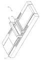
図1は本実施形態に係る塗布装置1の斜視図である。
図1に示すように、本実施形態に係る塗布装置1は、例えば液晶パネルなどに用いられるガラス基板上にレジストを塗布する塗布装置であり、基板搬送部2と、塗布部3と、管理部4とを主要な構成要素としている。この塗布装置1は、基板搬送部2によって基板を浮上させて搬送しつつ塗布部3によって当該基板上にレジストが塗布されるようになっており、管理部4によって塗布部3の状態が管理されるようになっている。
Hereinafter, embodiments of the present invention will be described with reference to the drawings.
FIG. 1 is a perspective view of a
As shown in FIG. 1, a
図2は塗布装置1の正面図、図3は塗布装置1の平面図、図4は塗布装置1の側面図である。これらの図を参照して、塗布装置1の詳細な構成を説明する。
2 is a front view of the
(基板搬送部)
まず、基板搬送部2の構成を説明する。
基板搬送部2は、基板搬入領域20と、塗布処理領域21と、基板搬出領域22と、搬送機構23と、これらを支持するフレーム部24とを有している。この基板搬送部2では、搬送機構23によって基板Sが基板搬入領域20、塗布処理領域21及び基板搬出領域22へと順に搬送されるようになっている。基板搬入領域20、塗布処理領域21及び基板搬出領域22は、基板搬送方向の上流側から下流側へこの順で配列されている。搬送機構23は、基板搬入領域20、塗布処理領域21及び基板搬出領域22の各部に跨るように当該各部の一側方に設けられている。
(Substrate transport section)
First, the structure of the board |
The
以下、塗布装置1の構成を説明するにあたり、表記の簡単のため、図中の方向をXYZ座標系を用いて説明する。基板搬送部2の長手方向であって基板の搬送方向をX方向と表記する。平面視でX方向(基板搬送方向)に直交する方向をY方向と表記する。X方向軸及びY方向軸を含む平面に垂直な方向をZ方向と表記する。なお、X方向、Y方向及びZ方向のそれぞれは、図中の矢印の方向が+方向、矢印の方向とは反対の方向が−方向であるものとする。
Hereinafter, in describing the configuration of the
基板搬入領域20は、装置外部から搬送されてきた基板Sを搬入する部位であり、搬入側ステージ25と、リフト機構26とを有している。
搬入側ステージ25は、フレーム部24の上部に設けられており、例えばSUSなどからなる平面視で矩形の板状部材である。この搬入側ステージ25は、X方向が長手になっている。搬入側ステージ25には、エア噴出孔25aと、昇降ピン出没孔25bとがそれぞれ複数設けられている。これらエア噴出孔25a及び昇降ピン出没孔25bは、搬入側ステージ25を貫通するように設けられている。
The substrate carry-in
The carry-in
エア噴出孔25aは、搬入側ステージ25のステージ表面25c上にエアを噴出する孔であり、例えば搬入側ステージ25のうち基板Sの通過する領域に平面視マトリクス状に配置されている。このエア噴出孔25aには図示しないエア供給源が接続されている。この搬入側ステージ25では、エア噴出孔25aから噴出されるエアによって基板Sを+Z方向に浮上させることができるようになっている。
The air ejection holes 25a are holes for ejecting air onto the
昇降ピン出没孔25bは、搬入側ステージ25のうち基板Sの搬入される領域に設けられている。当該昇降ピン出没孔25bは、ステージ表面25cに供給されたエアが漏れ出さない構成になっている。
The elevating
この搬入側ステージ25のうちY方向の両端部には、アライメント装置25dが1つずつ設けられている。アライメント装置25dは、搬入側ステージ25に搬入された基板Sの位置を合わせる装置である。各アライメント装置25dは長孔と当該長孔内に設けられた位置合わせ部材(図示しない)を有しており、搬入ステージ25に搬入される基板を両側から機械的に挟持するようになっている。
One
リフト機構26は、搬入側ステージ25の基板搬入位置の裏面側に設けられている。このリフト機構26は、昇降部材26aと、複数の昇降ピン26bとを有している。昇降部材26aは、図示しない駆動機構に接続されており、当該駆動機構の駆動によって昇降部材26aがZ方向に移動するようになっている。複数の昇降ピン26bは、昇降部材26aの上面から搬入側ステージ25へ向けて立設されている。各昇降ピン26bは、それぞれ上記の昇降ピン出没孔25bに平面視で重なる位置に配置されている。昇降部材26aがZ方向に移動することで、各昇降ピン26bが昇降ピン出没孔25bからステージ表面25c上に出没するようになっている。各昇降ピン26bの+Z方向の端部はそれぞれZ方向上の位置が揃うように設けられており、装置外部から搬送されてきた基板Sを水平な状態で保持することができるようになっている。
The
塗布処理領域21は、レジストの塗布が行われる部位であり、基板Sを浮上支持する処理ステージ27が設けられている。
処理ステージ27は、ステージ表面27cが例えば硬質アルマイトを主成分とする光吸収材料で覆われた平面視で矩形の板状部材であり、搬入側ステージ25に対して+X方向側に設けられている。処理ステージ27のうち光吸収材料で覆われた部分(反射抑制部)では、レーザ光などの光の反射が抑制されるようになっている。この処理ステージ27は、Y方向が長手になっている。処理ステージ27のY方向の寸法は、搬入側ステージ25のY方向の寸法とほぼ同一になっている。処理ステージ27には、複数のエア噴出孔27aと、複数のエア吸引孔27bとが設けられている。処理ステージ27には、X方向及びY方向にこのエア噴出孔27aとエア吸引孔27bとが交互に平面視マトリクス状に配列されており、1つのエア噴出孔27aと1つのエア吸引孔27bとが隣接して設けられている。これらエア噴出孔27a及びエア吸引孔27bは、処理ステージ27を貫通するように設けられている。
The
The
エア噴出孔27aには、図示しないエア供給源が接続されている。このエア供給源には、エア噴出孔27aから噴出するエアの圧力や流量を調節する図示しない調節機構が設けられている。このエア吸引孔27bには、図示しないポンプが接続されている。ポンプの吸引力を調節することにより、処理ステージ27に供給されたエアの吸引圧を調節することができるようになっている。
An air supply source (not shown) is connected to the
処理ステージ27では、エア噴出孔27aのピッチが搬入側ステージ25に設けられるエア噴出孔25aのピッチよりも狭く、搬入側ステージ25に比べてエア噴出孔27aが密に設けられている。このため、この処理ステージ27では他のステージに比べて基板の浮上量を高精度で調節できるようになっており、基板の浮上量が例えば100μm以下、好ましくは50μm以下となるように制御することが可能になっている。
In the
基板搬出領域22は、レジストが塗布された基板Sを装置外部へ搬出する部位であり、搬出側ステージ28と、リフト機構29とを有している。この搬出側ステージ28は、処理ステージ27に対して+X方向側に設けられており、基板搬入領域20に設けられた搬入側ステージ25とほぼ同様の材質、寸法から構成されている。搬出側ステージ28には、搬入側ステージ25と同様、エア噴出孔28a及び昇降ピン出没孔28bが設けられている。リフト機構29は、搬出側ステージ28の基板搬出位置の裏面側に設けられており、例えばフレーム部24に支持されている。リフト機構29の昇降部材29a及び昇降ピン29bは、基板搬入領域20に設けられたリフト機構26の各部位と同様の構成になっている。このリフト機構29は、搬出側ステージ28上の基板Sを外部装置へと搬出する際に、基板Sの受け渡しのため昇降ピン29bによって基板Sを持ち上げることができるようになっている。
The substrate carry-out
搬送機構23は、搬送機23aと、真空パッド23bと、レール23cとを有している。搬送機23aは内部に例えばリニアモータが設けられた構成になっており、当該リニアモータが駆動することによって搬送機23aがレール23c上を移動可能になっている。この搬送機23aは、所定の部分23dが平面視で基板Sの−Y方向端部に重なるように配置されている。この基板Sに重なる部分23dは、基板Sを浮上させたときの基板裏面の高さ位置よりも低い位置に設けられている。
The
真空パッド23bは、搬送機23aのうち上記基板Sに重なる部分23dに複数配列されている。この真空パッド23bは、基板Sを真空吸着させる吸着面を有しており、当該吸着面が上方を向くように配置されている。真空パッド23bは、吸着面が基板Sの裏面端部を吸着することで当該基板Sを保持可能になっている。各真空パッド23bは搬送機23aの上面からの高さ位置が調節可能になっており、例えば基板Sの浮上量に応じて真空パッド23bの高さ位置を上下させることができるようになっている。レール23cは、搬入側ステージ25、処理ステージ27及び搬出側ステージ28の側方に各ステージに跨って延在しており、当該レール23cを摺動することで搬送機23aが当該各ステージに沿って移動できるようになっている。
A plurality of
(塗布部)
次に、塗布部3の構成を説明する。
塗布部3は、基板S上にレジストを塗布する部分であり、門型フレーム31と、ノズル32とを有している。
門型フレーム31は、支柱部材31aと、架橋部材31bとを有しており、処理ステージ27をY方向に跨ぐように設けられている。支柱部材31aは処理ステージ27のY方向側に1つずつ設けられており、各支柱部材31aがフレーム部24のY方向側の両側面にそれぞれ支持されている。各支柱部材31aは、上端部の高さ位置が揃うように設けられている。架橋部材31bは、各支柱部材31aの上端部の間に架橋されており、当該支柱部材31aに対して昇降可能となっている。
(Applying part)
Next, the configuration of the
The
The
この門型フレーム31は移動機構31cに接続されており、X方向に移動可能になっている。この移動機構31cによって門型フレーム31が管理部4との間で移動可能になっている。すなわち、門型フレーム31に設けられたノズル32が管理部4との間で移動可能になっている。また、この門型フレーム31は、図示しない移動機構によりZ方向にも移動可能になっている。
The
ノズル32は、一方向が長手の長尺状に構成されており、門型フレーム31の架橋部材31bの−Z方向側の面に設けられている。このノズル32のうち−Z方向の先端には、自身の長手方向に沿ってスリット状の開口部32aが設けられており、当該開口部32aからレジストが吐出されるようになっている。ノズル32は、開口部32aの長手方向がY方向に平行になると共に、当該開口部32aが処理ステージ27に対向するように配置されている。開口部32aの長手方向の寸法は搬送される基板SのY方向の寸法よりも小さくなっており、基板Sの周辺領域にレジストが塗布されないようになっている。ノズル32の内部にはレジストを開口部32aに流通させる図示しない流通路が設けられており、この流通路には図示しないレジスト供給源が接続されている。このレジスト供給源は例えば図示しないポンプを有しており、当該ポンプでレジストを開口部32aへと押し出すことで開口部32aからレジストが吐出されるようになっている。支柱部材31aには不図示の移動機構が設けられており、当該移動機構によって架橋部材31bに保持されたノズル32がZ方向に移動可能になっている。なお、ノズル32の開口部32a、すなわち、ノズル32の先端と当該ノズル先端に対向する対向面との間のZ方向上の距離を測定するセンサ33を架橋部材31bに取り付けておいても良い。
The
(管理部)
管理部4の構成を説明する。
管理部4は、基板Sに吐出されるレジスト(液状体)の吐出量が一定になるようにノズル32を管理する部位であり、基板搬送部2のうち塗布部3に対して−X方向側(基板搬送方向の上流側)に設けられている。この管理部4は、予備吐出機構41と、ディップ槽42と、ノズル洗浄装置43と、これらを収容する収容部44と、当該収容部を保持する保持部材45とを有している。保持部材45は、移動機構45aに接続されている。当該移動機構45aにより、収容部44がX方向に移動可能になっている。
(Management Department)
The configuration of the
The
図5は、管理部4の収容部材44内の構成を示す断面図である。
同図に示すように、予備吐出機構41、ディップ槽42及びノズル洗浄装置43は、−X方向側へこの順で配列されている。これら予備吐出機構41、ディップ槽42及びノズル洗浄装置43のY方向の各寸法は上記門型フレーム31の支柱部材31a間の距離よりも小さくなっており、上記門型フレーム31が各部位を跨いでアクセスできるようになっている。
FIG. 5 is a cross-sectional view illustrating a configuration inside the
As shown in the figure, the
予備吐出機構41は、レジストを予備的に吐出する部分であり、予備吐出プレート41aと、予備吐出面洗浄ユニット41bとを有している。当該予備吐出機構41はノズル32に最も近くに設けられており、予備吐出動作を行った後すぐに塗布動作へと移ることができるようになっている。ディップ槽42は、内部にシンナーなどの溶剤が貯留された液体槽である。ノズル洗浄装置43は、ノズル32の開口部32a近傍をリンス洗浄する装置であり、Y方向に移動する図示しない洗浄機構と、当該洗浄機構を移動させる図示しない移動機構とを有している。この移動機構は、洗浄機構よりも−X方向側に設けられている。ノズル洗浄装置43は、移動機構が設けられる分、予備吐出機構41及びディップ槽42に比べてX方向の寸法が大きくなっている。勿論、予備吐出機構41、ディップ槽42、ノズル洗浄装置43の配置については、本実施形態の配置に限られず、他の配置であっても構わない。
The
図6は、予備吐出機構41の構成を示す平面図である。
予備吐出プレート41aは、例えば石材などの材料からなる板状部材であり、その長手方向(Y方向)がノズル32の長手方向に一致している。当該予備吐出プレート41aのうち+Z方向側の面はレジストが吐出される予備吐出面41cになっている。この予備吐出面41cは平坦に形成されており、図中のXY平面に対して平行になっている。
FIG. 6 is a plan view showing the configuration of the
The
予備吐出面洗浄ユニット41bは、予備吐出面41cを洗浄する部位であり、図示しない移動機構によってY方向に移動可能に設けられている。この予備吐出面洗浄ユニット41bは、図7に示すように、洗浄液供給部41eと、スキージ(掻き取り部)41fとを有している。洗浄液供給部41eは予備吐出面41cに洗浄液を供給するようになっており、スキージ41fは洗浄液と共に予備吐出面41cを摺動するようになっている。スキージ41fは、予備吐出面41cに対して所定の角度、例えば45°程度傾いている。
The preliminary discharge
次に、上記のように構成された塗布装置1の動作を説明する。
図8〜図11は、塗布装置1の動作過程を示す平面図である。各図を参照して、基板Sにレジストを塗布する動作を説明する。この動作では、基板Sを基板搬入領域20に搬入し、当該基板Sを浮上させて搬送しつつ塗布処理領域21でレジストを塗布し、当該レジストを塗布した基板Sを基板搬出領域22から搬出する。図8〜図11には門型フレーム31及び管理部4の輪郭のみを破線で示し、ノズル32及び処理ステージ27の構成を判別しやすくした。以下、各部分における詳細な動作を説明する。
Next, operation | movement of the
8-11 is a top view which shows the operation | movement process of the
基板搬入領域20に基板を搬入する前に、塗布装置1をスタンバイさせておく。具体的には、搬入側ステージ25の基板搬入位置の−Y方向側に搬送機23aを配置させ、真空パッド23bの高さ位置を基板の浮上高さ位置に合わせておくと共に、搬入側ステージ25のエア噴出孔25a、処理ステージ27のエア噴出孔27a、エア吸引孔27b及び搬出側ステージ28のエア噴出孔28aからそれぞれエアを噴出又は吸引し、各ステージ表面に基板が浮上する程度にエアが供給された状態にしておく。
Before the substrate is carried into the substrate carry-in
この状態で、例えば図示しない搬送アームなどによって外部から図8に示す基板搬入位置に基板Sが搬送されてきたら、昇降部材26aを+Z方向に移動させて昇降ピン26bを昇降ピン出没孔25bからステージ表面25cに突出させる。そして、昇降ピン26bによって基板Sが持ち上げられ、当該基板Sの受け取りが行われる。また、アライメント装置25dの長孔から位置合わせ部材をステージ表面25cに突出させておく。
In this state, for example, when the substrate S is transferred from the outside to the substrate carry-in position shown in FIG. 8 by a transfer arm (not shown), the elevating
基板Sを受け取った後、昇降部材26aを下降させて昇降ピン26bを昇降ピン出没孔25b内に収容する。ステージ表面25cにはエアの層が形成されているため、基板Sは当該エアによりステージ表面25cに対して浮上した状態で保持される。基板Sがエア層の表面に到達した際、アライメント装置25dの位置合わせ部材によって基板Sの位置合わせが行われ、基板搬入位置の−Y方向側に配置された搬送機23aの真空パッド23bを基板Sの−Y方向側端部に真空吸着させる。基板Sの−Y方向側端部が吸着された状態を図8に示す。真空パッド23bによって基板Sの−Y方向側端部が吸着された後、搬送機23aをレール23cに沿って移動させる。基板Sが浮上した状態になっているため、搬送機23aの駆動力を比較的小さくしても基板Sはレール23cに沿ってスムーズに移動する。
After receiving the board | substrate S, the raising / lowering
基板Sの搬送方向先端がノズル32の開口部32aの位置に到達したら、図9に示すように、ノズル32の開口部32aから基板Sへ向けてレジストを吐出する。レジストの吐出は、ノズル32の位置を固定させ搬送機23aによって基板Sを搬送させながら行う。基板Sの移動に伴い、図10に示すように基板S上にレジスト膜Rが塗布されていく。基板Sがレジストを吐出する開口部32aの下を通過することにより、基板Sの所定の領域にレジスト膜Rが形成される。
When the front end of the substrate S in the transport direction reaches the position of the
レジスト膜Rの形成された基板Sは、搬送機23aによって搬出側ステージ28へと搬送される。搬出側ステージ28では、ステージ表面28cに対して浮上した状態で、図11に示す基板搬出位置まで基板Sが搬送される。
The substrate S on which the resist film R is formed is transported to the unloading
基板Sが基板搬出位置に到達したら、真空パッド23bの吸着を解除し、リフト機構29の昇降部材29aを+Z方向に移動させる。すると、昇降ピン29bが昇降ピン出没孔28bから基板Sの裏面へ突出し、基板Sが昇降ピン29bによって持ち上げられる。この状態で、例えば搬出側ステージ28の+X方向側に設けられた外部の搬送アームが搬出側ステージ28にアクセスし、基板Sを受け取る。基板Sを搬送アームに渡した後、搬送機23aを再び搬入側ステージ25の基板搬入位置まで戻し、次の基板Sが搬送されるまで待機させる。
When the substrate S reaches the substrate unloading position, the suction of the
次の基板Sが搬送されてくるまでの間、塗布部3では、ノズル32の吐出状態を保持するための予備吐出が行われる。図12に示すように、門型フレーム31を管理部4の位置まで−X方向へ移動させる。
Until the next substrate S is transported, the
管理部4の位置まで門型フレーム31を移動させた後、図14に示すように、門型フレーム31の位置を調整してノズル32をノズル洗浄装置43にアクセスさせる。ノズル洗浄装置43では、ノズル32の開口部32a近傍に向けてシンナー等の洗浄液を吐出するとともに、必要に応じて窒素ガスをシンナーと同時にノズル32の開口部32aに吐出しながら、管理部4をノズル32の長手方向にスキャンさせることによって、ノズル32に付着したレジストを除去する。
After the
ノズル32の洗浄後、図14に示すように、当該ノズル32をディップ槽42内にアクセスさせる。ディップ層42では、ノズル32の開口部32aをディップ槽42に貯留された溶剤(シンナー)の蒸気雰囲気に曝すことでノズル32の乾燥を防止する。なお、この乾燥防止処理は、毎回の予備吐出動作の際に行う必要は無く、この処理を飛ばして次の処理に移ることも可能である。
After cleaning the
ノズル32の乾燥防止処理を行った後(ディップ槽42にアクセスしなかった場合はノズル32の洗浄後)、図14に示すように、当該ノズル32を予備吐出ユニット42にアクセスさせる。予備吐出ユニット42では、開口部32aと予備吐出面との間の距離を測定しながらノズル32の開口部32aをZ方向上の所定の位置に移動させ、ノズル32を−X方向へ移動させながら開口部32aから予備吐出面41cに向けてレジストRを予備吐出する。
After the drying prevention processing for the nozzle 32 (when the
予備吐出後、予備吐出面洗浄ユニット41bによって予備吐出面41cを洗浄する。具体的には、スキージ41fを予備吐出面41cに当接させ、洗浄液供給部41eから洗浄液を供給しながら予備吐出面洗浄ユニット41bを予備吐出面41cの+Y方向若しくは−Y方向に走査させる。洗浄液によってレジストが予備吐出面41cから除去されると共に、スキージ41fによって当該除去されたレジスト及び洗浄液が予備吐出面41cの外側に掻き出される。
After the preliminary discharge, the
予備吐出面洗浄ユニット41bによる洗浄開始とほぼ同じタイミングで、門型フレーム31を元の位置に戻す。次の基板Sが搬送されてきたら、図13に示すように移動機構32bによってノズル32をZ方向上の所定の位置に移動させる。このように、基板Sにレジスト膜Rを塗布する塗布動作と予備吐出動作とを繰り返し行わせることで、基板Sには良質なレジスト膜Rが形成されることになる。
The
このように、本実施形態によれば、基板Sを浮上させて搬送する基板搬送部2と、基板搬送部2により搬送中の基板Sに対して液状体を塗布する塗布部3と、塗布部3の予備吐出動作に際して塗布部3から液状体を塗布される略平面の予備吐出面41cを備えた予備吐出機構41とを有することとしたので、洗浄液を大量に配置させること無く、予備吐出を行うことができる。この予備吐出機構41は板状部材からなる予備吐出プレート41aを有し、当該予備吐出プレート41aの一方の面を予備吐出面41cとして用いるので、当該予備吐出プレート41aの被吐出領域を移動させることなく予備吐出動作を行うことができる。これにより、大掛かりな移動機構などが必要なくなるため、予備吐出機構41を小型化することができる。また、予備吐出面41cが基板搬送部3と平面視で重なる位置に配置されているので、塗布装置1全体の外形寸法を小さく抑えることが可能となる。
As described above, according to the present embodiment, the
また、本実施形態によれば、予備吐出機構41の近傍にノズル32の洗浄を行うノズル洗浄装置43及びノズル32の乾燥を防止するディップ槽42を並設してなる管理部4が設けられていることとしたので、予備吐出動作、ノズル32の洗浄、ノズル32の乾燥防止を纏めて行うことができる。これにより、ノズル32の吐出状態を効率的に維持することができる。
In addition, according to the present embodiment, the
また、本実施形態によれば、予備吐出面41cを洗浄する予備吐出面洗浄ユニット41bが予備吐出機構41に設けられているので、例えば予備吐出が行われた後、予備吐出面41cを洗浄させることができる。これにより、当該予備吐出面41cにおいて予備吐出動作を繰り返し行うことができる。また、当該予備吐出面洗浄ユニット41bが、予備吐出面41cに洗浄液を供給する洗浄液供給部41eと、洗浄液とともに予備吐出面41cの液状体を掻き取るスキージ41fとを有することとしたので、洗浄液の使用量を極力抑えつつ、予備吐出面41cを効率的に洗浄することができる。
Further, according to the present embodiment, since the preliminary discharge
本発明の技術範囲は上記実施形態に限定されるものではなく、本発明の趣旨を逸脱しない範囲で適宜変更を加えることができる。 The technical scope of the present invention is not limited to the above-described embodiment, and appropriate modifications can be made without departing from the spirit of the present invention.
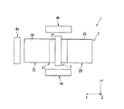
上記実施形態においては、管理部4を基板搬送部2に平面視で重なる位置に配置した構成を例に挙げて説明したが、これに限られることは無く、例えば図15に示すように、管理部4を+X方向の側方4aに配置した構成であっても良い。また、同図に示すように、基板搬送部2のY方向の側方4b、4cに配置した構成であっても構わない。
In the above embodiment, the configuration in which the
塗布装置1の全体構成については、上記実施形態では、搬送機構23を各ステージの−Y方向側に配置する構成としたが、これに限られることは無い。例えば、搬送機構23を各ステージの+Y方向側に配置する構成であっても構わない。また、図16に示すように、各ステージの−Y方向側には上記の搬送機構23(搬送機23a、真空パッド23b、レール23c)を配置し、+Y方向側には当該搬送機構23と同一の構成の搬送機構53(搬送機53a、真空パッド53b、レール53c)を配置して、搬送機構23と搬送機構53とで異なる基板を搬送できるように構成しても構わない。例えば、同図に示すように搬送機構23には基板S1を搬送させ、搬送機構53には基板S2を搬送させるようにする。この場合、搬送機構23と搬送機構53とで基板を交互に搬送することが可能となるため、スループットが向上することになる。また、上記の基板S、S1、S2の半分程度の面積を有する基板を搬送する場合には、例えば搬送機構23と搬送機構53とで1枚ずつ保持し、搬送機構23と搬送機構53とを+X方向に並進させることによって、2枚の基板を同時に搬送させることができる。このような構成により、スループットを向上させることができる。
About the whole structure of the
また、上記実施形態においては、予備吐出を行うときに予備吐出面41cの位置を固定し、移動機構31cによってノズル32をX方向に移動させるようにとしたが、これに限られることは無く、ノズル32と予備吐出面41cとが相対移動するのであれば他の動作であっても構わない。例えば、ノズル32を固定させておき予備吐出プレート41aを収容する収容部材44を移動させるようにしても構わないし、ノズル32及び収容部材44のそれぞれを移動させるようにしても構わない。
In the above embodiment, the position of the
また、上記実施形態においては、予備吐出プレート41aの+Z方向側の面を予備吐出面41cとしたが、これに限られることは無く、予備吐出面41cがほぼ平面であれば他の構成であっても構わない。例えば、予備吐出プレート41aを設けずに、管理部4の各構成要素を収容する収容部材の底面上を予備吐出面とし、当該収容部材の底面上に直接予備吐出を行う構成であっても構わない。
In the above embodiment, the surface on the + Z direction side of the
また、上記実施形態においては、ノズル洗浄装置43、ディップ槽42及び予備吐出機構41の各部位を管理部4としてまとめて配置したが、これに限られることは無く、これらの各部位を別々に配置する構成であっても構わない。例えば予備吐出機構41のみをノズル32の近傍に設け、ノズル洗浄装置43及びディップ槽42を管理部4内に配置する構成であっても構わない。この場合、例えば予備吐出のみを連続で複数回行い、当該複数回毎にノズル32の洗浄、乾燥防止処理を行うようにすることができる。これにより、予備吐出動作を迅速に行うことができる。
Moreover, in the said embodiment, although each part of the nozzle washing | cleaning
1…塗布装置 2…基板搬送部 3…塗布部 4…管理部 21…塗布処理領域 23…搬送機構 27…処理ステージ 31…門型フレーム 32…ノズル 41…予備吐出機構 41a…予備吐出プレート 43…ノズル洗浄機構 43c…予備吐出面 S…基板 R…レジスト膜
DESCRIPTION OF
Claims (10)
前記基板搬送部により搬送中の前記基板に対して液状体を塗布する塗布部と、
前記塗布部の予備吐出動作に際して前記塗布部から前記液状体を塗布される略平面の予備吐出面を備えた予備吐出部と、
を有し、
前記塗布部は、前記液状体を吐出するノズルを有し、
前記ノズルは、前記予備吐出面に沿って移動可能である
ことを特徴とする塗布装置。 A substrate transport unit that floats and transports the substrate;
An application unit that applies a liquid material to the substrate being conveyed by the substrate conveyance unit;
A preliminary ejection unit having a substantially planar preliminary ejection surface to which the liquid material is applied from the application unit during the preliminary ejection operation of the application unit;
I have a,
The application unit has a nozzle for discharging the liquid material,
The coating apparatus , wherein the nozzle is movable along the preliminary ejection surface .
ことを特徴とする請求項1に記載の塗布装置。 Wherein in the vicinity of the preliminary ejection section, coating apparatus according to claim 1, characterized in that at least one is provided in the drying prevention mechanism for preventing the drying of the nozzle cleaning mechanism and the nozzle for cleaning of the nozzle.
ことを特徴とする請求項2に記載の塗布装置。 The coating apparatus according to claim 2, further comprising a management unit in which the preliminary discharge unit, the nozzle cleaning mechanism, and the drying prevention mechanism are arranged in parallel.
ことを特徴とする請求項1から請求項3のいずれか1項に記載の塗布装置。 The said preliminary discharge part has a plate-shaped member, and uses one surface of the said plate-shaped member as said preliminary discharge surface. The coating device of any one of Claims 1-3 characterized by the above-mentioned.
ことを特徴とする請求項1から請求項4のいずれか1項に記載の塗布装置。 5. The coating apparatus according to claim 1, wherein the preliminary ejection surface is disposed at a position overlapping the substrate transport unit in plan view.
ことを特徴とする請求項1から請求項4のいずれか1項に記載の塗布装置。 The coating apparatus according to claim 1, wherein the preliminary discharge surface is disposed on a side of the substrate transport unit.
ことを特徴とする請求項6に記載の塗布装置。 The coating apparatus according to claim 6, wherein the preliminary discharge surface is disposed on a side of the substrate transfer unit in the substrate transfer direction.
ことを特徴とする請求項1から請求項7のいずれか1項に記載の塗布装置。 The coating apparatus according to any one of claims 1 to 7, further comprising a moving mechanism that allows the coating unit and the preliminary discharge surface to move relative to each other.
ことを特徴とする請求項1から請求項8のいずれか1項に記載の塗布装置。 The coating apparatus according to any one of claims 1 to 8, wherein a preliminary discharge surface cleaning mechanism for cleaning the preliminary discharge surface is provided in the preliminary discharge unit.
ことを特徴とする請求項9に記載の塗布装置。 The preliminary discharge surface cleaning mechanism includes a cleaning liquid supply unit that supplies a cleaning liquid to the preliminary discharge surface, and a scraping unit that scrapes the liquid material on the preliminary discharge surface together with the cleaning liquid. 9. The coating apparatus according to 9.
Priority Applications (3)
| Application Number | Priority Date | Filing Date | Title |
|---|---|---|---|
| JP2007178360A JP5337357B2 (en) | 2007-07-06 | 2007-07-06 | Coating device |
| TW097122281A TWI351321B (en) | 2007-07-06 | 2008-06-13 | Coating applicator |
| KR1020080063989A KR100982154B1 (en) | 2007-07-06 | 2008-07-02 | Coating applicator |
Applications Claiming Priority (1)
| Application Number | Priority Date | Filing Date | Title |
|---|---|---|---|
| JP2007178360A JP5337357B2 (en) | 2007-07-06 | 2007-07-06 | Coating device |
Publications (2)
| Publication Number | Publication Date |
|---|---|
| JP2009016654A JP2009016654A (en) | 2009-01-22 |
| JP5337357B2 true JP5337357B2 (en) | 2013-11-06 |
Family
ID=40357187
Family Applications (1)
| Application Number | Title | Priority Date | Filing Date |
|---|---|---|---|
| JP2007178360A Active JP5337357B2 (en) | 2007-07-06 | 2007-07-06 | Coating device |
Country Status (3)
| Country | Link |
|---|---|
| JP (1) | JP5337357B2 (en) |
| KR (1) | KR100982154B1 (en) |
| TW (1) | TWI351321B (en) |
Families Citing this family (3)
| Publication number | Priority date | Publication date | Assignee | Title |
|---|---|---|---|---|
| JP5349770B2 (en) * | 2007-07-17 | 2013-11-20 | 東京応化工業株式会社 | Coating apparatus and coating method |
| KR101052463B1 (en) * | 2010-09-17 | 2011-07-28 | 주식회사 케이씨텍 | Inline type substrate coater apparatus |
| JP5771432B2 (en) * | 2011-04-13 | 2015-08-26 | 東京応化工業株式会社 | Coating device |
Family Cites Families (9)
| Publication number | Priority date | Publication date | Assignee | Title |
|---|---|---|---|---|
| JP3254574B2 (en) * | 1996-08-30 | 2002-02-12 | 東京エレクトロン株式会社 | Method and apparatus for forming coating film |
| JP2000164491A (en) * | 1998-11-26 | 2000-06-16 | Sony Corp | Resist applying device |
| JP4040025B2 (en) * | 2004-02-20 | 2008-01-30 | 東京エレクトロン株式会社 | Coating film forming device |
| JP4455102B2 (en) | 2004-03-10 | 2010-04-21 | 大日本スクリーン製造株式会社 | Substrate processing equipment |
| JP4526288B2 (en) * | 2004-03-25 | 2010-08-18 | 東京応化工業株式会社 | Adjusting device and adjusting method for slit nozzle tip |
| JP4429073B2 (en) * | 2004-05-20 | 2010-03-10 | 東京応化工業株式会社 | Pre-discharge device for slit coater |
| KR100700180B1 (en) | 2004-12-31 | 2007-03-27 | 엘지.필립스 엘시디 주식회사 | Slit coater having pre-spreading unit and method of coating using thereof |
| JP2006263535A (en) * | 2005-03-23 | 2006-10-05 | Toppan Printing Co Ltd | Slit coater |
| KR101097519B1 (en) * | 2005-06-25 | 2011-12-22 | 엘지디스플레이 주식회사 | Coating apparatus and method of forming coating layer |
-
2007
- 2007-07-06 JP JP2007178360A patent/JP5337357B2/en active Active
-
2008
- 2008-06-13 TW TW097122281A patent/TWI351321B/en active
- 2008-07-02 KR KR1020080063989A patent/KR100982154B1/en active IP Right Grant
Also Published As
| Publication number | Publication date |
|---|---|
| TW200914145A (en) | 2009-04-01 |
| JP2009016654A (en) | 2009-01-22 |
| KR100982154B1 (en) | 2010-09-14 |
| TWI351321B (en) | 2011-11-01 |
| KR20090004689A (en) | 2009-01-12 |
Similar Documents
| Publication | Publication Date | Title |
|---|---|---|
| JP4942589B2 (en) | Coating apparatus and coating method | |
| TWI444321B (en) | Coating applicator, method of transferring a substrate and method of coating | |
| JP5301120B2 (en) | Cleaning device, cleaning method, preliminary discharge device, and coating device | |
| JP5352080B2 (en) | NOZZLE CLEANING DEVICE, NOZZLE CLEANING METHOD, COATING DEVICE, AND COATING METHOD | |
| JP5771432B2 (en) | Coating device | |
| JP2009011917A (en) | Cleaning device, cleaning method, preparatory ejection device, and coating device | |
| JP5303129B2 (en) | Coating apparatus and coating method | |
| JP5303125B2 (en) | Coating apparatus and coating method | |
| JP5550882B2 (en) | Coating device | |
| JP5518284B2 (en) | NOZZLE CLEANING DEVICE, NOZZLE CLEANING METHOD, COATING DEVICE, AND COATING METHOD | |
| JP5337357B2 (en) | Coating device | |
| JP5144977B2 (en) | Cleaning device, cleaning method, preliminary discharge device, coating device, and preliminary discharge method | |
| JP5303231B2 (en) | Coating device | |
| JP5349770B2 (en) | Coating apparatus and coating method | |
| JP5244445B2 (en) | Coating device | |
| JP5255823B2 (en) | Pre-discharge device and pre-discharge method | |
| JP2009043829A (en) | Coater and coating method | |
| JP5244446B2 (en) | Coating device | |
| JP5303232B2 (en) | Nozzle, coating apparatus, and nozzle maintenance method | |
| JP5518427B2 (en) | Coating device | |
| JP5355881B2 (en) | Coating device | |
| JP5469992B2 (en) | Coating method and coating apparatus | |
| JP2014003317A (en) | Coating device |
Legal Events
| Date | Code | Title | Description |
|---|---|---|---|
| A621 | Written request for application examination |
Free format text: JAPANESE INTERMEDIATE CODE: A621 Effective date: 20100520 |
|
| A131 | Notification of reasons for refusal |
Free format text: JAPANESE INTERMEDIATE CODE: A131 Effective date: 20121113 |
|
| TRDD | Decision of grant or rejection written | ||
| A01 | Written decision to grant a patent or to grant a registration (utility model) |
Free format text: JAPANESE INTERMEDIATE CODE: A01 Effective date: 20130709 |
|
| A61 | First payment of annual fees (during grant procedure) |
Free format text: JAPANESE INTERMEDIATE CODE: A61 Effective date: 20130805 |
|
| R150 | Certificate of patent or registration of utility model |
Ref document number: 5337357 Country of ref document: JP Free format text: JAPANESE INTERMEDIATE CODE: R150 Free format text: JAPANESE INTERMEDIATE CODE: R150 |