JP5334633B2 - リザーバタンクおよびこれを用いたブレーキ装置 - Google Patents
リザーバタンクおよびこれを用いたブレーキ装置 Download PDFInfo
- Publication number
- JP5334633B2 JP5334633B2 JP2009058127A JP2009058127A JP5334633B2 JP 5334633 B2 JP5334633 B2 JP 5334633B2 JP 2009058127 A JP2009058127 A JP 2009058127A JP 2009058127 A JP2009058127 A JP 2009058127A JP 5334633 B2 JP5334633 B2 JP 5334633B2
- Authority
- JP
- Japan
- Prior art keywords
- hydraulic fluid
- reservoir tank
- chamber
- fluid supply
- volume
- Prior art date
- Legal status (The legal status is an assumption and is not a legal conclusion. Google has not performed a legal analysis and makes no representation as to the accuracy of the status listed.)
- Active
Links
- 239000012530 fluid Substances 0.000 claims abstract description 217
- 238000003860 storage Methods 0.000 claims abstract description 33
- 239000007788 liquid Substances 0.000 description 16
- 238000000034 method Methods 0.000 description 8
- 238000003466 welding Methods 0.000 description 8
- 235000014676 Phragmites communis Nutrition 0.000 description 6
- 238000004891 communication Methods 0.000 description 6
- 238000004519 manufacturing process Methods 0.000 description 6
- 238000003780 insertion Methods 0.000 description 5
- 230000037431 insertion Effects 0.000 description 5
- 230000015572 biosynthetic process Effects 0.000 description 4
- 210000000078 claw Anatomy 0.000 description 3
- 230000007423 decrease Effects 0.000 description 3
- 238000001514 detection method Methods 0.000 description 3
- 238000010438 heat treatment Methods 0.000 description 3
- 230000002093 peripheral effect Effects 0.000 description 3
- 238000011109 contamination Methods 0.000 description 2
- 238000013461 design Methods 0.000 description 2
- 230000002452 interceptive effect Effects 0.000 description 2
- 238000000465 moulding Methods 0.000 description 2
- 238000005192 partition Methods 0.000 description 2
- 238000012805 post-processing Methods 0.000 description 2
- 238000005086 pumping Methods 0.000 description 2
- 238000010586 diagram Methods 0.000 description 1
- 230000000694 effects Effects 0.000 description 1
- 238000010137 moulding (plastic) Methods 0.000 description 1
- 238000003825 pressing Methods 0.000 description 1
- 238000012545 processing Methods 0.000 description 1
Images


Classifications
-
- B—PERFORMING OPERATIONS; TRANSPORTING
- B60—VEHICLES IN GENERAL
- B60T—VEHICLE BRAKE CONTROL SYSTEMS OR PARTS THEREOF; BRAKE CONTROL SYSTEMS OR PARTS THEREOF, IN GENERAL; ARRANGEMENT OF BRAKING ELEMENTS ON VEHICLES IN GENERAL; PORTABLE DEVICES FOR PREVENTING UNWANTED MOVEMENT OF VEHICLES; VEHICLE MODIFICATIONS TO FACILITATE COOLING OF BRAKES
- B60T11/00—Transmitting braking action from initiating means to ultimate brake actuator without power assistance or drive or where such assistance or drive is irrelevant
- B60T11/10—Transmitting braking action from initiating means to ultimate brake actuator without power assistance or drive or where such assistance or drive is irrelevant transmitting by fluid means, e.g. hydraulic
- B60T11/26—Reservoirs
Landscapes
- Engineering & Computer Science (AREA)
- Transportation (AREA)
- Mechanical Engineering (AREA)
- Transmission Of Braking Force In Braking Systems (AREA)
- Valves And Accessory Devices For Braking Systems (AREA)
Description
上部の高さをそれぞれ単純に大きくすることで、空気室の容積を大きくすることが考えられる。
更に、本発明のリザーバタンクは、前記容積増大室形成部が、リザーバタンクの車両搭載時の他の車両部品と干渉しない空間に延設されていることを特徴としている。
更に、本発明のリザーバタンクは、前記容積増大室の底部が、前記筒状部内の前記室に向かって下り坂に傾斜していることを特徴としている。
図1に示すように、この例の液圧ブレーキ装置1は、基本的には従来公知の一般的な2系統の液圧ブレーキ装置と同じである。すなわち、液圧ブレーキ装置1は、ブレーキペダル2、倍力装置3、タンデムマスタシリンダ4、リザーバタンク5、およびブレーキシリンダ6を備えている。
バタンク5内に作動液量を検出する液量検出部28が設けられている。図3(b)に示すように、液量検出部28は、中間体9に設けられた有底略角筒状のスイッチ収容部29と、このスイッチ収容部29に収容されるノーマルクローズ型のリードスイッチ30とを有している。このリードスイッチ30は、リザーバタンク5内の作動液の液面が警告表示要の液面(MINより若干上方)より高いときは、作動液の液面に応じて上下動するフロートに設けられたマグネットによりオンとなって、警告表示は行われない。また、作動液の液面が警告表示要の液面以下になると、マグネットがフロートとともに下降してリードスイッチ30がオフとなり、警告表示が行われるようになっている。
リザーバタンク5の全体を従来のリザーバタンクとほぼ同じ大きさに形成することができ、リザーバタンク5の大型化を抑制できる。したがって、リザーバタンク5を比較的狭いエンジンルームの限られた空間内に他の部品と干渉することなく、効率よく搭載することができる。
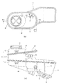
前述の例では、リザーバタンク5が下部体8、中間体9、および上部体10を有するとともに、これらを水平面または略水平面で溶着しているが、図4(a)および(b)に示すように、この例のリザーバタンク5は、中間体9がなく、下部体8および上部体10を有している。その場合、上部体10は第1上部体10aと第2上部体10bとから構成されている。そして、第1上部体10aが前述の例の中間体9、上部体10、および容積増大室形成部25の一部を構成し、また、第2上部体10bが前述の例の容積増大室形成部25の残部を構成している。図5(d)に示すように、この例の容積増大室形成部25内の容積増大室24の底部24bは水平にされていて、前述の例のように傾斜していない。
34bからなるガイド34が設けられている。そして、ガイドレール33の上端部のT字部33aに一対の部材34a,34bが摺動可能に係合することで、第2上部体10bが
水平を保持しながら、ガイドレール33にガイドされて第1上部体10aの溶着面の方へ移動されるようになっている。
また、本発明に係るブレーキ装置は、リザーバタンクに貯留された作動液を用いて車輪にブレーキをかける液圧ブレーキ装置に好適に利用することができる。
液通路、18…作動液供給口、20…円筒状部材、21…作動液供給通路、22…長円筒状部、23…室、23a…空気室、24…容積増大室、24a…空気室、24b…底部、25…容積増大室形成部、28…液量検出部、29…スイッチ収容部、29a…係止孔、30…リードスイッチ、30b…弾性係止爪、31…工具挿通孔、33…ガイドレール、34…ガイド、34a,34b…部材
Claims (6)
- 作動液供給口と、この作動液供給口から作動液が供給される作動液供給部と、この作動液供給部の作動液が作動液通路を介して供給されることで前記作動液を貯留する作動液貯留室と、前記作動液供給口と前記作動液供給部との間に設けられ、内部に前記作動液供給部に連通する室を有する筒状部とを少なくとも備えるリザーバタンクにおいて、
前記筒状部に、内部に前記室に連通し作動液供給口から筒状部に至る作動液供給通路にない容積増大室を有する容積増大室形成部が設けられ、
前記容積増大室の少なくとも一部は、作動液の最大限貯留レベルであるMAXラインより上方に位置していることを特徴とするリザーバタンク。 - 前記容積増大室形成部は、前記筒状部から水平または略水平に延設されていることを特徴とする請求項1に記載のリザーバタンク。
- 前記容積増大室形成部は、リザーバタンクの車両搭載時の他の車両部品と干渉しない空間に延設されていることを特徴とする請求項2に記載のリザーバタンク。
- 前記容積増大室形成部は、前記作動液通路の上方に延設されていることを特徴とする請求項3に記載のリザーバタンク。
- 前記容積増大室の底部は、前記筒状部内の前記室に向かって下り坂に傾斜していることを特徴とする請求項1ないし4のいずれか1に記載のリザーバタンク。
- 作動液を貯留するリザーバタンクと、前記リザーバタンク内の作動液が供給されるとともに作動時にブレーキ圧を発生するマスタシリンダと、前記マスタシリンダからの液圧で作動するブレーキシリンダとを少なくとも備え、
前記リザーバタンクが請求項1ないし5のいずれか1に記載のリザーバタンクであることを特徴とするブレーキ装置。
Priority Applications (3)
| Application Number | Priority Date | Filing Date | Title |
|---|---|---|---|
| JP2009058127A JP5334633B2 (ja) | 2009-03-11 | 2009-03-11 | リザーバタンクおよびこれを用いたブレーキ装置 |
| EP10001970.2A EP2228272B1 (en) | 2009-03-11 | 2010-02-26 | Reservoir tank and brake device using the reservoir tank |
| US12/721,831 US8607563B2 (en) | 2009-03-11 | 2010-03-11 | Reservoir tank and brake device using the reservoir tank |
Applications Claiming Priority (1)
| Application Number | Priority Date | Filing Date | Title |
|---|---|---|---|
| JP2009058127A JP5334633B2 (ja) | 2009-03-11 | 2009-03-11 | リザーバタンクおよびこれを用いたブレーキ装置 |
Publications (3)
| Publication Number | Publication Date |
|---|---|
| JP2010208547A JP2010208547A (ja) | 2010-09-24 |
| JP2010208547A5 JP2010208547A5 (ja) | 2012-03-29 |
| JP5334633B2 true JP5334633B2 (ja) | 2013-11-06 |
Family
ID=42309463
Family Applications (1)
| Application Number | Title | Priority Date | Filing Date |
|---|---|---|---|
| JP2009058127A Active JP5334633B2 (ja) | 2009-03-11 | 2009-03-11 | リザーバタンクおよびこれを用いたブレーキ装置 |
Country Status (3)
| Country | Link |
|---|---|
| US (1) | US8607563B2 (ja) |
| EP (1) | EP2228272B1 (ja) |
| JP (1) | JP5334633B2 (ja) |
Families Citing this family (7)
| Publication number | Priority date | Publication date | Assignee | Title |
|---|---|---|---|---|
| JP5597436B2 (ja) * | 2010-04-28 | 2014-10-01 | 日立オートモティブシステムズ株式会社 | リザーバ |
| KR102116724B1 (ko) * | 2016-03-11 | 2020-06-01 | 로베르트 보쉬 게엠베하 | 일체형 파워 브레이크 유닛을 위한 내부 도관을 구비한 브레이크 저장조 |
| US10717474B2 (en) | 2017-03-21 | 2020-07-21 | Arctic Cat Inc. | Cab and fasteners for vehicle cab |
| US11014419B2 (en) * | 2017-03-21 | 2021-05-25 | Arctic Cat Inc. | Off-road utility vehicle |
| DE102019200807A1 (de) * | 2019-01-23 | 2020-07-23 | Continental Teves Ag & Co. Ohg | Verfahren zum Betreiben einer Bremsanlage und Bremsanlage |
| DE102019219869A1 (de) * | 2019-12-17 | 2021-06-17 | Continental Teves Ag & Co. Ohg | Hydraulisches Bremsgerät für eine Kraftfahrzeugbremsanlage mit einer verbesserten Behälteranbindung |
| CN111661020B (zh) * | 2020-05-13 | 2021-12-24 | 北京新能源汽车股份有限公司 | 车辆及其制动方法和系统 |
Family Cites Families (8)
| Publication number | Priority date | Publication date | Assignee | Title |
|---|---|---|---|---|
| GB1574608A (en) * | 1976-06-24 | 1980-09-10 | Girling Ltd | Reservoirs for vehicle hydraulic systems |
| DE4029931C2 (de) * | 1990-09-21 | 1999-03-25 | Teves Gmbh Alfred | Ausgleichbehälter für eine hydraulische Bremsanlage |
| US5957545A (en) * | 1996-09-03 | 1999-09-28 | Aisin Seiki Kabushiki Kaisha | Fluid holding vehicle reservoir for preventing leakage of fluid |
| JP4427657B2 (ja) * | 2000-02-08 | 2010-03-10 | マツダ株式会社 | 自動車用ブレーキ装置のリザーブタンク構造 |
| JP2004074837A (ja) * | 2002-08-09 | 2004-03-11 | Bosch Automotive Systems Corp | 作動液リザ−バ |
| DE10310170A1 (de) | 2003-03-08 | 2004-09-16 | Wiesauplast Kunststoff Und Formenbau Gmbh & Co. Kg | Behälter zur Druckmittelspeisung |
| JP4834598B2 (ja) * | 2007-04-20 | 2011-12-14 | 日立オートモティブシステムズ株式会社 | リザーバ |
| DE102007037225A1 (de) * | 2007-07-11 | 2009-01-15 | Continental Teves Ag & Co. Ohg | Ausgleichsbehälter für eine hydraulische Kraftfahrzeugbremsanlage |
-
2009
- 2009-03-11 JP JP2009058127A patent/JP5334633B2/ja active Active
-
2010
- 2010-02-26 EP EP10001970.2A patent/EP2228272B1/en active Active
- 2010-03-11 US US12/721,831 patent/US8607563B2/en active Active
Also Published As
| Publication number | Publication date |
|---|---|
| US20100229547A1 (en) | 2010-09-16 |
| US8607563B2 (en) | 2013-12-17 |
| EP2228272A1 (en) | 2010-09-15 |
| JP2010208547A (ja) | 2010-09-24 |
| EP2228272B1 (en) | 2016-07-27 |
Similar Documents
| Publication | Publication Date | Title |
|---|---|---|
| JP5334633B2 (ja) | リザーバタンクおよびこれを用いたブレーキ装置 | |
| US10046744B2 (en) | Brake apparatus | |
| JP2010208548A (ja) | リザーバタンクおよびこれを用いたブレーキ装置 | |
| JP5021295B2 (ja) | 圧力流体供給用コンテナ | |
| JP2005508783A (ja) | 液圧ブレーキシステムのための小型タンク | |
| EP2327597B1 (en) | Reservoir and brake device using same | |
| KR20110061080A (ko) | 하이브리드 제동장치 | |
| JP2011025737A (ja) | リザーバタンクおよびこれを用いたブレーキ装置 | |
| JP3967651B2 (ja) | 車両用液圧マスタシリンダのリザーバ | |
| JP2016130092A (ja) | 車両用液圧マスタシリンダのリザーバ | |
| WO2011074223A1 (ja) | リザーバタンクおよびこれを備える液圧作動装置 | |
| JP6616370B2 (ja) | リザーバタンク | |
| JP2010064680A (ja) | リザーバタンクおよびこれを用いたブレーキ装置 | |
| JPH0445974Y2 (ja) | ||
| JP2011025736A (ja) | リザーバタンクおよびこれを用いたブレーキ装置 | |
| JP6241207B2 (ja) | 制動制御装置 | |
| JP2019172118A (ja) | リザーバタンク | |
| JP2010076724A (ja) | リザーバタンクおよびこれを用いたブレーキ装置 | |
| JP2015074367A (ja) | リザーバタンク及びこれを用いたブレーキシステム | |
| JPH08216866A (ja) | リザーバ | |
| JP3540135B2 (ja) | 車両用作動液リザーバ | |
| JP5913973B2 (ja) | キャップおよびこれを用いたリザーバタンク | |
| JP2016187974A (ja) | リザーバタンク | |
| CN117698674A (zh) | 液压阀及具有该液压阀的制动系统 | |
| JP2011079364A (ja) | リザーバタンクおよびこれを用いたブレーキ装置 |
Legal Events
| Date | Code | Title | Description |
|---|---|---|---|
| A521 | Request for written amendment filed |
Free format text: JAPANESE INTERMEDIATE CODE: A523 Effective date: 20120210 |
|
| A621 | Written request for application examination |
Free format text: JAPANESE INTERMEDIATE CODE: A621 Effective date: 20120216 |
|
| A977 | Report on retrieval |
Free format text: JAPANESE INTERMEDIATE CODE: A971007 Effective date: 20130122 |
|
| A131 | Notification of reasons for refusal |
Free format text: JAPANESE INTERMEDIATE CODE: A131 Effective date: 20130206 |
|
| A521 | Request for written amendment filed |
Free format text: JAPANESE INTERMEDIATE CODE: A523 Effective date: 20130301 |
|
| RD05 | Notification of revocation of power of attorney |
Free format text: JAPANESE INTERMEDIATE CODE: A7425 Effective date: 20130301 |
|
| TRDD | Decision of grant or rejection written | ||
| A01 | Written decision to grant a patent or to grant a registration (utility model) |
Free format text: JAPANESE INTERMEDIATE CODE: A01 Effective date: 20130723 |
|
| A61 | First payment of annual fees (during grant procedure) |
Free format text: JAPANESE INTERMEDIATE CODE: A61 Effective date: 20130730 |
|
| R151 | Written notification of patent or utility model registration |
Ref document number: 5334633 Country of ref document: JP Free format text: JAPANESE INTERMEDIATE CODE: R151 |
|
| R250 | Receipt of annual fees |
Free format text: JAPANESE INTERMEDIATE CODE: R250 |
|
| R250 | Receipt of annual fees |
Free format text: JAPANESE INTERMEDIATE CODE: R250 |
|
| R250 | Receipt of annual fees |
Free format text: JAPANESE INTERMEDIATE CODE: R250 |
|
| R250 | Receipt of annual fees |
Free format text: JAPANESE INTERMEDIATE CODE: R250 |
|
| R250 | Receipt of annual fees |
Free format text: JAPANESE INTERMEDIATE CODE: R250 |
|
| R250 | Receipt of annual fees |
Free format text: JAPANESE INTERMEDIATE CODE: R250 |
|
| R250 | Receipt of annual fees |
Free format text: JAPANESE INTERMEDIATE CODE: R250 |
|
| R250 | Receipt of annual fees |
Free format text: JAPANESE INTERMEDIATE CODE: R250 |