JP5305599B2 - 半導体装置およびその製造方法 - Google Patents
半導体装置およびその製造方法 Download PDFInfo
- Publication number
- JP5305599B2 JP5305599B2 JP2007038288A JP2007038288A JP5305599B2 JP 5305599 B2 JP5305599 B2 JP 5305599B2 JP 2007038288 A JP2007038288 A JP 2007038288A JP 2007038288 A JP2007038288 A JP 2007038288A JP 5305599 B2 JP5305599 B2 JP 5305599B2
- Authority
- JP
- Japan
- Prior art keywords
- wiring
- layer
- barrier layer
- cual
- barrier
- Prior art date
- Legal status (The legal status is an assumption and is not a legal conclusion. Google has not performed a legal analysis and makes no representation as to the accuracy of the status listed.)
- Active
Links
Images
Classifications
-
- H—ELECTRICITY
- H01—ELECTRIC ELEMENTS
- H01L—SEMICONDUCTOR DEVICES NOT COVERED BY CLASS H10
- H01L23/00—Details of semiconductor or other solid state devices
- H01L23/52—Arrangements for conducting electric current within the device in operation from one component to another, i.e. interconnections, e.g. wires, lead frames
- H01L23/522—Arrangements for conducting electric current within the device in operation from one component to another, i.e. interconnections, e.g. wires, lead frames including external interconnections consisting of a multilayer structure of conductive and insulating layers inseparably formed on the semiconductor body
- H01L23/532—Arrangements for conducting electric current within the device in operation from one component to another, i.e. interconnections, e.g. wires, lead frames including external interconnections consisting of a multilayer structure of conductive and insulating layers inseparably formed on the semiconductor body characterised by the materials
- H01L23/53204—Conductive materials
- H01L23/53209—Conductive materials based on metals, e.g. alloys, metal silicides
- H01L23/53228—Conductive materials based on metals, e.g. alloys, metal silicides the principal metal being copper
- H01L23/53233—Copper alloys
-
- H—ELECTRICITY
- H01—ELECTRIC ELEMENTS
- H01L—SEMICONDUCTOR DEVICES NOT COVERED BY CLASS H10
- H01L21/00—Processes or apparatus adapted for the manufacture or treatment of semiconductor or solid state devices or of parts thereof
- H01L21/70—Manufacture or treatment of devices consisting of a plurality of solid state components formed in or on a common substrate or of parts thereof; Manufacture of integrated circuit devices or of parts thereof
- H01L21/71—Manufacture of specific parts of devices defined in group H01L21/70
- H01L21/768—Applying interconnections to be used for carrying current between separate components within a device comprising conductors and dielectrics
- H01L21/76838—Applying interconnections to be used for carrying current between separate components within a device comprising conductors and dielectrics characterised by the formation and the after-treatment of the conductors
- H01L21/76841—Barrier, adhesion or liner layers
- H01L21/76843—Barrier, adhesion or liner layers formed in openings in a dielectric
- H01L21/76846—Layer combinations
-
- H—ELECTRICITY
- H01—ELECTRIC ELEMENTS
- H01L—SEMICONDUCTOR DEVICES NOT COVERED BY CLASS H10
- H01L21/00—Processes or apparatus adapted for the manufacture or treatment of semiconductor or solid state devices or of parts thereof
- H01L21/70—Manufacture or treatment of devices consisting of a plurality of solid state components formed in or on a common substrate or of parts thereof; Manufacture of integrated circuit devices or of parts thereof
- H01L21/71—Manufacture of specific parts of devices defined in group H01L21/70
- H01L21/768—Applying interconnections to be used for carrying current between separate components within a device comprising conductors and dielectrics
- H01L21/76838—Applying interconnections to be used for carrying current between separate components within a device comprising conductors and dielectrics characterised by the formation and the after-treatment of the conductors
- H01L21/76841—Barrier, adhesion or liner layers
- H01L21/76843—Barrier, adhesion or liner layers formed in openings in a dielectric
- H01L21/76849—Barrier, adhesion or liner layers formed in openings in a dielectric the layer being positioned on top of the main fill metal
-
- H—ELECTRICITY
- H01—ELECTRIC ELEMENTS
- H01L—SEMICONDUCTOR DEVICES NOT COVERED BY CLASS H10
- H01L21/00—Processes or apparatus adapted for the manufacture or treatment of semiconductor or solid state devices or of parts thereof
- H01L21/70—Manufacture or treatment of devices consisting of a plurality of solid state components formed in or on a common substrate or of parts thereof; Manufacture of integrated circuit devices or of parts thereof
- H01L21/71—Manufacture of specific parts of devices defined in group H01L21/70
- H01L21/768—Applying interconnections to be used for carrying current between separate components within a device comprising conductors and dielectrics
- H01L21/76838—Applying interconnections to be used for carrying current between separate components within a device comprising conductors and dielectrics characterised by the formation and the after-treatment of the conductors
- H01L21/76841—Barrier, adhesion or liner layers
- H01L21/76853—Barrier, adhesion or liner layers characterized by particular after-treatment steps
- H01L21/76861—Post-treatment or after-treatment not introducing additional chemical elements into the layer
- H01L21/76864—Thermal treatment
-
- H—ELECTRICITY
- H01—ELECTRIC ELEMENTS
- H01L—SEMICONDUCTOR DEVICES NOT COVERED BY CLASS H10
- H01L21/00—Processes or apparatus adapted for the manufacture or treatment of semiconductor or solid state devices or of parts thereof
- H01L21/70—Manufacture or treatment of devices consisting of a plurality of solid state components formed in or on a common substrate or of parts thereof; Manufacture of integrated circuit devices or of parts thereof
- H01L21/71—Manufacture of specific parts of devices defined in group H01L21/70
- H01L21/768—Applying interconnections to be used for carrying current between separate components within a device comprising conductors and dielectrics
- H01L21/76838—Applying interconnections to be used for carrying current between separate components within a device comprising conductors and dielectrics characterised by the formation and the after-treatment of the conductors
- H01L21/76841—Barrier, adhesion or liner layers
- H01L21/76871—Layers specifically deposited to enhance or enable the nucleation of further layers, i.e. seed layers
- H01L21/76873—Layers specifically deposited to enhance or enable the nucleation of further layers, i.e. seed layers for electroplating
-
- H—ELECTRICITY
- H01—ELECTRIC ELEMENTS
- H01L—SEMICONDUCTOR DEVICES NOT COVERED BY CLASS H10
- H01L23/00—Details of semiconductor or other solid state devices
- H01L23/52—Arrangements for conducting electric current within the device in operation from one component to another, i.e. interconnections, e.g. wires, lead frames
- H01L23/522—Arrangements for conducting electric current within the device in operation from one component to another, i.e. interconnections, e.g. wires, lead frames including external interconnections consisting of a multilayer structure of conductive and insulating layers inseparably formed on the semiconductor body
- H01L23/532—Arrangements for conducting electric current within the device in operation from one component to another, i.e. interconnections, e.g. wires, lead frames including external interconnections consisting of a multilayer structure of conductive and insulating layers inseparably formed on the semiconductor body characterised by the materials
- H01L23/53204—Conductive materials
- H01L23/53209—Conductive materials based on metals, e.g. alloys, metal silicides
- H01L23/53228—Conductive materials based on metals, e.g. alloys, metal silicides the principal metal being copper
- H01L23/53238—Additional layers associated with copper layers, e.g. adhesion, barrier, cladding layers
-
- H—ELECTRICITY
- H01—ELECTRIC ELEMENTS
- H01L—SEMICONDUCTOR DEVICES NOT COVERED BY CLASS H10
- H01L2924/00—Indexing scheme for arrangements or methods for connecting or disconnecting semiconductor or solid-state bodies as covered by H01L24/00
- H01L2924/0001—Technical content checked by a classifier
- H01L2924/0002—Not covered by any one of groups H01L24/00, H01L24/00 and H01L2224/00
Landscapes
- Engineering & Computer Science (AREA)
- Physics & Mathematics (AREA)
- Condensed Matter Physics & Semiconductors (AREA)
- General Physics & Mathematics (AREA)
- Computer Hardware Design (AREA)
- Microelectronics & Electronic Packaging (AREA)
- Power Engineering (AREA)
- Manufacturing & Machinery (AREA)
- Internal Circuitry In Semiconductor Integrated Circuit Devices (AREA)
Description
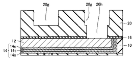
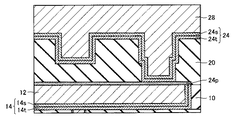
本発明にかかる半導体装置の一実施形態は、図1を参照して、第1の絶縁層10内に形成されている第1の配線12と、第1の絶縁層10および第1の配線12上に形成されている第2の絶縁層20内に形成されている第2の配線22とを有する半導体装置である。ここで、第1の配線12および第2の配線22の少なくともいずれかはCuAl合金で形成されているCuAl配線である。また、第2の配線22は、そのビアプラグ部22vで、複数のバリア層24を介在して、第1の配線12に電気的に接続している。また、複数のバリア層24において、CuAl配線と接触するCuAl接触バリア層は、窒素原子含有量が10原子%未満、好ましくは1原子%未満である。ここで、バリア層24sは、配線間の電気抵抗を低減する観点から、金属原子を主として含み、具体的には金属原子含有量が90原子%以上であることが好ましい。
本発明にかかる半導体装置の他の実施形態は、図7を参照して、第1の絶縁層10内に形成されている第1の配線12と、第1の絶縁層10および第1の配線12上に形成されている第2の絶縁層20内に形成されている第2の配線22とを有する半導体装置である。ここで、第1の配線12および第2の配線22の少なくともいずれかはCuAl合金で形成されているCuAl配線である。また、第2の配線22は、そのビアプラグ部22vで、複数のバリア層24を介在して、第1の配線12に電気的に接続している。また、複数のバリア層24において、CuAl配線と接触するCuAl接触バリア層は、窒素原子の含有量が10原子%未満、好ましくは1原子%未満である。ここで、本実施形態の半導体装置は、第1の配線12と接触する第1のバリア層24pは、第2の配線22のビアプラグ部22vの直下に選択的に形成されている点に特徴がある。
本発明にかかる半導体装置のさらに他の実施形態は、図14を参照して、第1の絶縁層10内に形成されている第1の配線12と、第1の絶縁層10および第1の配線12上に形成されている第2の絶縁層20内に形成されている第2の配線22とを有する半導体装置である。ここで、第1の配線12および第2の配線22の少なくともいずれかはCuAl合金で形成されているCuAl配線である。また、第2の配線22は、そのビアプラグ部22vで、金属で形成されている複数のバリア層24を介在して、第1の配線12に電気的に接続している。また、複数のバリア層24において、CuAl配線と接触するCuAl接触バリア層は、窒素原子含有量が10原子%未満、好ましくは1原子%未満である。ここで、本実施形態の半導体装置は、第1の配線12と接触する第1のバリア層24pは、第1の配線12の直上に選択的に形成されている点に特徴がある。
本発明にかかる半導体装置のさらに他の実施形態は、図21を参照して、配線が3層以上積層された多層配線構造を有する。ここで、多層配線構造は、実施形態1〜3の第1の配線および第2の配線を含む。また、多層配線構造において、CuAl配線およびCu配線が混在していてもよい。すなわち、配線幅が小さく信頼性確保が厳しい層にはCuAl配線が好ましく用いられ、配線幅が大きくCuAl合金配線を用いなくても十分に信頼性の確保が可能な層にはより抵抗の低いCu配線が好ましく用いられる。
本発明にかかる半導体装置のさらに他の実施形態は、図22を参照して、配線が3層以上積層された多層配線構造を有する。ここで、多層配線層は、下層配線層301と上層配線層302とを含み、下層配線層301中の配線はCuAl配線212n,222nであり、上層配線層302中の配線はCu配線232mである。半導体装置において、下層配線層においては配線幅が小さく信頼性確保が厳しいためCuAl配線が好ましく用いられ、上層配線層においては低抵抗化のためCu配線が好ましく用いられる。
Claims (10)
- 第1の絶縁層内に形成されている第1の配線と、前記第1の絶縁層および前記第1の配線上に形成されている第2の絶縁層内に形成されている第2の配線とを有し、
前記第1の配線はCu配線であり、前記第2の配線はCuAl配線であって、
前記第2の配線は、複数のバリア層を介在して、前記第1の配線に電気的に接続しており、
前記複数のバリア層のうち少なくとも1つのバリア層は窒素原子含有量が10原子%以上であり、かつ、前記CuAl配線と接触するCuAl接触バリア層は窒素原子含有量が10原子%未満である半導体装置。 - 前記第1の配線と接触する第1のバリア層は、前記第2の配線のビアプラグ部の直下に選択的に形成されている請求項1に記載の半導体装置。
- 前記第1の配線と接触する第1のバリア層は、前記第1の配線の直上に選択的に形成されている請求項1に記載の半導体装置。
- 前記CuAl接触バリア層の窒素原子含有量が1原子%未満である請求項1に記載の半導体装置。
- 窒素原子含有量が10原子%以上である前記少なくとも1つのバリア層のうちの1つは、前記第1の配線たる前記Cu配線と接触するCu接触バリア層である請求項1に記載の半導体装置。
- 第1の絶縁層内に形成された第1の配線を準備する工程と、
前記第1の絶縁層および前記第1の配線上に第2の絶縁層を形成する工程と、
前記第2の絶縁層内に配線用溝および前記第1の配線に達するビアホールを形成する工程と、
前記配線用溝および前記ビアホール内に複数のバリア層を形成する工程と、
前記複数のバリア層上に第2の配線を形成する工程とを含み、
前記第1の配線はCu金属で形成され、前記第2の配線はCuAl合金で形成され、
前記複数のバリア層のうち少なくとも1つのバリア層は窒素原子含有量が10原子%以上であり、かつ、前記CuAl合金で形成された前記第2の配線と接触するCuAl接触バリア層は窒素原子含有量が10原子%未満である半導体装置の製造方法。 - 前記複数のバリア層を形成する工程において、前記第1の配線と接触する第1のバリア層を前記ビアホールの底面の直上に選択的に形成する請求項6に記載の半導体装置の製造方法。
- 窒素原子含有量が10原子%以上である前記少なくとも1つのバリア層のうちの1つは、前記Cu金属で形成された前記第1の配線と接触するCu接触バリア層である請求項6に記載の半導体装置の製造方法。
- 第1の絶縁層内に形成された第1の配線を準備する工程と、
前記第1の配線の直上に第1のバリア層を選択的に形成する工程と、
前記第1の絶縁層および前記第1のバリア層上に第2の絶縁層を形成する工程と、
前記第2の絶縁層内に配線用溝および前記第1のバリア層に達するビアホールを形成する工程と、
前記配線用溝および前記ビアホール内に1以上の他のバリア層を形成する工程と、
前記他のバリア層上に第2の配線を形成する工程とを含み、
前記第1の配線はCu金属で形成され、前記第2の配線はCuAl合金で形成され、
前記第1のバリア層および前記他のバリア層のうち少なくとも1つのバリア層は窒素原子含有量が10原子%以上であり、かつ、前記CuAl合金で形成された前記第2の配線と接触するCuAl接触バリア層は窒素原子含有量が10原子%未満である半導体装置の製造方法。 - 窒素原子含有量が10原子%以上である前記少なくとも1つのバリア層のうちの1つは、前記Cu金属で形成された前記第1の配線と接触するCu接触バリア層である請求項9に記載の半導体装置の製造方法。
Priority Applications (2)
| Application Number | Priority Date | Filing Date | Title |
|---|---|---|---|
| JP2007038288A JP5305599B2 (ja) | 2007-02-19 | 2007-02-19 | 半導体装置およびその製造方法 |
| US12/071,200 US20080197496A1 (en) | 2007-02-19 | 2008-02-19 | Semiconductor device having at least two layers of wirings stacked therein and method of manufacturing the same |
Applications Claiming Priority (1)
| Application Number | Priority Date | Filing Date | Title |
|---|---|---|---|
| JP2007038288A JP5305599B2 (ja) | 2007-02-19 | 2007-02-19 | 半導体装置およびその製造方法 |
Publications (3)
| Publication Number | Publication Date |
|---|---|
| JP2008205119A JP2008205119A (ja) | 2008-09-04 |
| JP2008205119A5 JP2008205119A5 (ja) | 2010-04-02 |
| JP5305599B2 true JP5305599B2 (ja) | 2013-10-02 |
Family
ID=39705945
Family Applications (1)
| Application Number | Title | Priority Date | Filing Date |
|---|---|---|---|
| JP2007038288A Active JP5305599B2 (ja) | 2007-02-19 | 2007-02-19 | 半導体装置およびその製造方法 |
Country Status (2)
| Country | Link |
|---|---|
| US (1) | US20080197496A1 (ja) |
| JP (1) | JP5305599B2 (ja) |
Families Citing this family (9)
| Publication number | Priority date | Publication date | Assignee | Title |
|---|---|---|---|---|
| US8404582B2 (en) * | 2010-05-04 | 2013-03-26 | International Business Machines Corporation | Structure and method for manufacturing interconnect structures having self-aligned dielectric caps |
| JP2012043977A (ja) | 2010-08-19 | 2012-03-01 | Renesas Electronics Corp | 半導体装置および半導体装置の製造方法 |
| US20140138837A1 (en) * | 2012-11-20 | 2014-05-22 | Stmicroelectronics, Inc. | Sandwiched diffusion barrier and metal liner for an interconnect structure |
| US9293412B2 (en) * | 2012-12-17 | 2016-03-22 | International Business Machines Corporation | Graphene and metal interconnects with reduced contact resistance |
| KR102624631B1 (ko) * | 2016-12-02 | 2024-01-12 | 삼성전자주식회사 | 반도체 장치 |
| KR102634781B1 (ko) | 2017-01-18 | 2024-02-13 | 삼성전자주식회사 | 자기 메모리 장치 |
| KR102450580B1 (ko) * | 2017-12-22 | 2022-10-07 | 삼성전자주식회사 | 금속 배선 하부의 절연층 구조를 갖는 반도체 장치 |
| JP7343407B2 (ja) * | 2020-01-15 | 2023-09-12 | 株式会社アルバック | 金属配線の形成方法及び金属配線構造体 |
| JP7449790B2 (ja) * | 2020-06-24 | 2024-03-14 | 株式会社アルバック | 金属配線の形成方法及び金属配線の構造体 |
Family Cites Families (9)
| Publication number | Priority date | Publication date | Assignee | Title |
|---|---|---|---|---|
| US6346745B1 (en) * | 1998-12-04 | 2002-02-12 | Advanced Micro Devices, Inc. | Cu-A1 combined interconnect system |
| JP3643533B2 (ja) * | 2000-12-27 | 2005-04-27 | 株式会社東芝 | 半導体装置およびその製造方法 |
| US6737747B2 (en) * | 2002-01-15 | 2004-05-18 | International Business Machines Corporation | Advanced BEOL interconnect structures with low-k PE CVD cap layer and method thereof |
| JP3992588B2 (ja) * | 2002-10-23 | 2007-10-17 | 東京エレクトロン株式会社 | 成膜方法 |
| JP2004253781A (ja) * | 2003-01-31 | 2004-09-09 | Nec Electronics Corp | 半導体装置およびその製造方法 |
| US20040183202A1 (en) * | 2003-01-31 | 2004-09-23 | Nec Electronics Corporation | Semiconductor device having copper damascene interconnection and fabricating method thereof |
| JP4454242B2 (ja) * | 2003-03-25 | 2010-04-21 | 株式会社ルネサステクノロジ | 半導体装置およびその製造方法 |
| JP2007042662A (ja) * | 2003-10-20 | 2007-02-15 | Renesas Technology Corp | 半導体装置 |
| US7215006B2 (en) * | 2005-10-07 | 2007-05-08 | International Business Machines Corporation | Plating seed layer including an oxygen/nitrogen transition region for barrier enhancement |
-
2007
- 2007-02-19 JP JP2007038288A patent/JP5305599B2/ja active Active
-
2008
- 2008-02-19 US US12/071,200 patent/US20080197496A1/en not_active Abandoned
Also Published As
| Publication number | Publication date |
|---|---|
| US20080197496A1 (en) | 2008-08-21 |
| JP2008205119A (ja) | 2008-09-04 |
Similar Documents
| Publication | Publication Date | Title |
|---|---|---|
| JP5305599B2 (ja) | 半導体装置およびその製造方法 | |
| US9076792B2 (en) | Multi-layer barrier layer stacks for interconnect structures | |
| US8004087B2 (en) | Semiconductor device with dual damascene wirings and method for manufacturing same | |
| JP6415376B2 (ja) | 半導体装置およびその製造方法 | |
| US20070054489A1 (en) | Interconnect structures with encasing cap and methods of making thereof | |
| US6780769B2 (en) | Method of manufacturing structure for connecting interconnect lines including metal layer with thickness larger than thickness of metallic compound layer | |
| US20140024212A1 (en) | Multi-layer barrier layer for interconnect structure | |
| TW200426991A (en) | Semiconductor device and method of manufacturing the same | |
| US7659626B2 (en) | Semiconductor device including a barrier metal film | |
| JP5089850B2 (ja) | 半導体装置 | |
| US8338951B2 (en) | Metal line of semiconductor device having a diffusion barrier with an amorphous TaBN layer and method for forming the same | |
| US20140217591A1 (en) | Multi-layer barrier layer for interconnect structure | |
| JP2008159720A (ja) | 半導体装置並びに半導体装置の製造方法 | |
| US20060202336A1 (en) | Semiconductor device and method of fabricating a semiconductor device | |
| US7682967B2 (en) | Method of forming metal wire in semiconductor device | |
| KR100866138B1 (ko) | 반도체 소자의 배선 및 그의 형성방법 | |
| KR20080001905A (ko) | 반도체 소자의 금속 배선 형성방법 | |
| KR20090075499A (ko) | 반도체 소자의 금속배선 및 그 형성방법 | |
| JP2009170665A (ja) | 半導体装置および半導体装置の製造方法 | |
| JP2012039019A (ja) | 半導体装置およびその製造方法 | |
| JP2006270080A (ja) | 半導体装置及びその製造方法 | |
| JP2008147252A (ja) | 半導体装置とその製造方法 | |
| JP2006073792A (ja) | 半導体装置および半導体装置の製造方法 | |
| KR20080114057A (ko) | 반도체 소자의 배선 및 그의 형성방법 | |
| KR20100076332A (ko) | 반도체 소자의 금속 배선 형성 방법 |
Legal Events
| Date | Code | Title | Description |
|---|---|---|---|
| A521 | Written amendment |
Free format text: JAPANESE INTERMEDIATE CODE: A523 Effective date: 20100215 |
|
| A621 | Written request for application examination |
Free format text: JAPANESE INTERMEDIATE CODE: A621 Effective date: 20100215 |
|
| A711 | Notification of change in applicant |
Free format text: JAPANESE INTERMEDIATE CODE: A712 Effective date: 20100526 |
|
| A977 | Report on retrieval |
Free format text: JAPANESE INTERMEDIATE CODE: A971007 Effective date: 20121022 |
|
| A131 | Notification of reasons for refusal |
Free format text: JAPANESE INTERMEDIATE CODE: A131 Effective date: 20121030 |
|
| A521 | Written amendment |
Free format text: JAPANESE INTERMEDIATE CODE: A523 Effective date: 20121228 |
|
| A131 | Notification of reasons for refusal |
Free format text: JAPANESE INTERMEDIATE CODE: A131 Effective date: 20130319 |
|
| A521 | Written amendment |
Free format text: JAPANESE INTERMEDIATE CODE: A523 Effective date: 20130514 |
|
| TRDD | Decision of grant or rejection written | ||
| A01 | Written decision to grant a patent or to grant a registration (utility model) |
Free format text: JAPANESE INTERMEDIATE CODE: A01 Effective date: 20130618 |
|
| A61 | First payment of annual fees (during grant procedure) |
Free format text: JAPANESE INTERMEDIATE CODE: A61 Effective date: 20130625 |
|
| R150 | Certificate of patent or registration of utility model |
Free format text: JAPANESE INTERMEDIATE CODE: R150 Ref document number: 5305599 Country of ref document: JP Free format text: JAPANESE INTERMEDIATE CODE: R150 |
|
| S531 | Written request for registration of change of domicile |
Free format text: JAPANESE INTERMEDIATE CODE: R313531 |
|
| R350 | Written notification of registration of transfer |
Free format text: JAPANESE INTERMEDIATE CODE: R350 |


