JP5291981B2 - 防振装置のスリーブ嵌合構造 - Google Patents
防振装置のスリーブ嵌合構造 Download PDFInfo
- Publication number
- JP5291981B2 JP5291981B2 JP2008117631A JP2008117631A JP5291981B2 JP 5291981 B2 JP5291981 B2 JP 5291981B2 JP 2008117631 A JP2008117631 A JP 2008117631A JP 2008117631 A JP2008117631 A JP 2008117631A JP 5291981 B2 JP5291981 B2 JP 5291981B2
- Authority
- JP
- Japan
- Prior art keywords
- sleeve
- outer cylinder
- press
- diameter
- peripheral surface
- Prior art date
- Legal status (The legal status is an assumption and is not a legal conclusion. Google has not performed a legal analysis and makes no representation as to the accuracy of the status listed.)
- Active
Links
Images
Landscapes
- Vibration Prevention Devices (AREA)
- Springs (AREA)
Description
なお複数本の突条を形成するときは、それらの全てが、外筒の中心軸線に直交する一の環状円上に位置するものとする。
そしてこのことは、外筒上の突条の、圧入方向の先端面を截頭円錐面とする場合にもまた同様である。
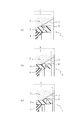
この一方で、突条を、拡径表面に面接触させる場合は、突条の弾性係合力を高めて、外筒をより効果的に抜け止めすることができる。
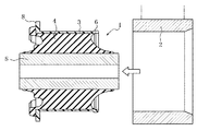
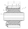
図中1は、ブッシュタイプの防振装置を、2はブッシュタイプの防振装置1を圧入される、剛性のスリーブをそれぞれ示す。
前者によるときは、突条6および拡径表面7等の多少の加工誤差の有無のいかんにかかわらず、突条6をもって、拡径表面7を確実に弾性押圧することができ、また、後者によるときは、大きな押圧力の作用下で、外筒3をより効果的に抜け止めすることができる。
なおこの抜け止めに関しては、突条6および拡径表面7のそれぞれを、拡径表面7をもって突条7を包み込むような形態を選択した場合により顕著なものとなる。
2 スリーブ
3 外筒
4 ゴム弾性体
5 内筒
6 突条
7 拡径表面
l 圧入長さ
L スリーブの軸線方向長さ
Claims (6)
- 外筒と、この外筒の内周面に接合させた筒状の弾性体とを具える防振装置を、外筒の縮径変形下でスリーブに圧入して、外筒の外周面をスリーブの内周面に摩擦係合させてなる防振装置のスリーブ嵌合構造であって、
合成樹脂製の外筒の、スリーブへの圧入長さを、スリーブの軸線方向長さより短かくするとともに、その外筒の、圧入方向の先端外周面に、半径方向外方へ突出させて形成されて、外筒の周方向に延びる突条を、スリーブの端部分に形成されて、スリーブの端縁側に向けて穴径を次第に増加する截頭円錐面としてなる拡径表面に、半径方向外向きの弾性復元力の作用下で弾性的に接触させてなる防振装置のスリーブ嵌合構造。 - 前記突条を外筒の全周にわたって環状に連続させて形成してなる請求項1に記載の防振装置のスリーブ嵌合構造。
- 前記突条の圧入方向の先端面を截頭円錐面としてなる請求項1または2に記載の防振装置のスリーブ嵌合構造。
- 外筒の、圧入方向の後端に、スリーブの端面に当接する外向きフランジを設けてなる請求項1〜3のいずれかに記載の防振装置のスリーブ嵌合構造。
- 外筒の突条を、スリーブの拡径表面に線接触させてなる請求項1〜4のいずれかに記載の防振装置のスリーブ嵌合構造。
- 外筒の突条を、スリーブの拡径方向に面接触させてなる請求項1〜4のいずれかに記載の防振装置のスリーブ嵌合構造。
Priority Applications (1)
| Application Number | Priority Date | Filing Date | Title |
|---|---|---|---|
| JP2008117631A JP5291981B2 (ja) | 2008-04-28 | 2008-04-28 | 防振装置のスリーブ嵌合構造 |
Applications Claiming Priority (1)
| Application Number | Priority Date | Filing Date | Title |
|---|---|---|---|
| JP2008117631A JP5291981B2 (ja) | 2008-04-28 | 2008-04-28 | 防振装置のスリーブ嵌合構造 |
Publications (2)
| Publication Number | Publication Date |
|---|---|
| JP2009264555A JP2009264555A (ja) | 2009-11-12 |
| JP5291981B2 true JP5291981B2 (ja) | 2013-09-18 |
Family
ID=41390638
Family Applications (1)
| Application Number | Title | Priority Date | Filing Date |
|---|---|---|---|
| JP2008117631A Active JP5291981B2 (ja) | 2008-04-28 | 2008-04-28 | 防振装置のスリーブ嵌合構造 |
Country Status (1)
| Country | Link |
|---|---|
| JP (1) | JP5291981B2 (ja) |
Cited By (1)
| Publication number | Priority date | Publication date | Assignee | Title |
|---|---|---|---|---|
| WO2022229527A1 (fr) | 2021-04-29 | 2022-11-03 | Psa Automobiles Sa | Dispositif cale de train arrière fusible en cas de choc arrière pour augmenter le rendement de compressibilité de la structure |
Families Citing this family (2)
| Publication number | Priority date | Publication date | Assignee | Title |
|---|---|---|---|---|
| JP5572414B2 (ja) * | 2010-02-04 | 2014-08-13 | 株式会社ブリヂストン | 防振装置の製造方法 |
| JP5707113B2 (ja) * | 2010-12-02 | 2015-04-22 | 株式会社ブリヂストン | 防振装置 |
Family Cites Families (6)
| Publication number | Priority date | Publication date | Assignee | Title |
|---|---|---|---|---|
| JPH0577637U (ja) * | 1992-03-23 | 1993-10-22 | 東海ゴム工業株式会社 | ブッシュ |
| JPH0741090U (ja) * | 1993-12-22 | 1995-07-21 | 豊生ブレーキ工業株式会社 | ボディーマウント |
| JP2001074080A (ja) * | 1999-09-07 | 2001-03-23 | Toyo Tire & Rubber Co Ltd | 弾性ブッシュおよびその組付体 |
| JP3731488B2 (ja) * | 2001-03-22 | 2006-01-05 | 東海ゴム工業株式会社 | 防振装置 |
| JP4016836B2 (ja) * | 2002-12-27 | 2007-12-05 | 東海ゴム工業株式会社 | 筒形防振装置 |
| JP3767545B2 (ja) * | 2002-11-26 | 2006-04-19 | 東海ゴム工業株式会社 | 筒形防振装置 |
-
2008
- 2008-04-28 JP JP2008117631A patent/JP5291981B2/ja active Active
Cited By (2)
| Publication number | Priority date | Publication date | Assignee | Title |
|---|---|---|---|---|
| WO2022229527A1 (fr) | 2021-04-29 | 2022-11-03 | Psa Automobiles Sa | Dispositif cale de train arrière fusible en cas de choc arrière pour augmenter le rendement de compressibilité de la structure |
| FR3122356A1 (fr) | 2021-04-29 | 2022-11-04 | Psa Automobiles Sa | Dispositif CALE de train AR fusible en cas de choc AR pour augmenter le rendement de compressibilité de la structure. |
Also Published As
| Publication number | Publication date |
|---|---|
| JP2009264555A (ja) | 2009-11-12 |
Similar Documents
| Publication | Publication Date | Title |
|---|---|---|
| JP5665259B2 (ja) | 軟質部材の取付構造 | |
| JP2006144972A (ja) | 防振ブッシュ組付構造 | |
| JP6343535B2 (ja) | 筒型防振装置 | |
| EP2143972B1 (en) | Bump stopper | |
| JP5291981B2 (ja) | 防振装置のスリーブ嵌合構造 | |
| JP4046010B2 (ja) | ダイナミックダンパ | |
| EP1035352A3 (en) | Vibration isolator | |
| JP2009505031A (ja) | ハウジング内の軸受レース用取付け装置 | |
| JP2010091014A (ja) | 防振装置 | |
| JP5964200B2 (ja) | リバウンドラバー | |
| JP5140484B2 (ja) | 弾性ブッシュ | |
| US20080036205A1 (en) | Piping joint | |
| JP5084410B2 (ja) | プロペラシャフト用ダイナミックダンパ | |
| JP4026609B2 (ja) | 筒型ダイナミックダンパ | |
| JP2001295886A (ja) | 防振装置 | |
| JP3717710B2 (ja) | スプリングシートラバー | |
| JPH08210407A (ja) | メンバマウント | |
| JP7446200B2 (ja) | シリンダ装置 | |
| JP5184287B2 (ja) | 防振ブッシュ | |
| JP2009063063A (ja) | ダイナミックダンパの取付構造 | |
| JP2007176274A (ja) | スタビライザブッシュ | |
| JP2010255799A (ja) | 防振装置の支持構造 | |
| JP5707113B2 (ja) | 防振装置 | |
| JP2590378Y2 (ja) | 揺動ないし球面運動などが可能な継手構造物用ダストシール | |
| JPH06229437A (ja) | 車両用サスペンションのバウンドバンパ |
Legal Events
| Date | Code | Title | Description |
|---|---|---|---|
| A621 | Written request for application examination |
Free format text: JAPANESE INTERMEDIATE CODE: A621 Effective date: 20110419 |
|
| A977 | Report on retrieval |
Free format text: JAPANESE INTERMEDIATE CODE: A971007 Effective date: 20120813 |
|
| A131 | Notification of reasons for refusal |
Free format text: JAPANESE INTERMEDIATE CODE: A131 Effective date: 20121218 |
|
| A521 | Request for written amendment filed |
Free format text: JAPANESE INTERMEDIATE CODE: A523 Effective date: 20130207 |
|
| TRDD | Decision of grant or rejection written | ||
| A01 | Written decision to grant a patent or to grant a registration (utility model) |
Free format text: JAPANESE INTERMEDIATE CODE: A01 Effective date: 20130514 |
|
| A61 | First payment of annual fees (during grant procedure) |
Free format text: JAPANESE INTERMEDIATE CODE: A61 Effective date: 20130610 |
|
| R150 | Certificate of patent or registration of utility model |
Ref document number: 5291981 Country of ref document: JP Free format text: JAPANESE INTERMEDIATE CODE: R150 |
|
| R250 | Receipt of annual fees |
Free format text: JAPANESE INTERMEDIATE CODE: R250 |
|
| R250 | Receipt of annual fees |
Free format text: JAPANESE INTERMEDIATE CODE: R250 |
|
| R250 | Receipt of annual fees |
Free format text: JAPANESE INTERMEDIATE CODE: R250 |
|
| R250 | Receipt of annual fees |
Free format text: JAPANESE INTERMEDIATE CODE: R250 |
|
| R250 | Receipt of annual fees |
Free format text: JAPANESE INTERMEDIATE CODE: R250 |
|
| R250 | Receipt of annual fees |
Free format text: JAPANESE INTERMEDIATE CODE: R250 |
|
| R250 | Receipt of annual fees |
Free format text: JAPANESE INTERMEDIATE CODE: R250 |
|
| S111 | Request for change of ownership or part of ownership |
Free format text: JAPANESE INTERMEDIATE CODE: R313111 |
|
| S531 | Written request for registration of change of domicile |
Free format text: JAPANESE INTERMEDIATE CODE: R313531 |
|
| R350 | Written notification of registration of transfer |
Free format text: JAPANESE INTERMEDIATE CODE: R350 |
|
| R250 | Receipt of annual fees |
Free format text: JAPANESE INTERMEDIATE CODE: R250 |
|
| R250 | Receipt of annual fees |
Free format text: JAPANESE INTERMEDIATE CODE: R250 |