JP5291981B2 - Sleeve fitting structure of vibration isolator - Google Patents
Sleeve fitting structure of vibration isolator Download PDFInfo
- Publication number
- JP5291981B2 JP5291981B2 JP2008117631A JP2008117631A JP5291981B2 JP 5291981 B2 JP5291981 B2 JP 5291981B2 JP 2008117631 A JP2008117631 A JP 2008117631A JP 2008117631 A JP2008117631 A JP 2008117631A JP 5291981 B2 JP5291981 B2 JP 5291981B2
- Authority
- JP
- Japan
- Prior art keywords
- sleeve
- outer cylinder
- press
- diameter
- peripheral surface
- Prior art date
- Legal status (The legal status is an assumption and is not a legal conclusion. Google has not performed a legal analysis and makes no representation as to the accuracy of the status listed.)
- Active
Links
Images
Abstract
Description
この発明は、外筒と、この外筒の内周面に接合させた筒状の弾性体、たとえばゴム弾性体とを具え、このゴム弾性体の内周面に接合させた内筒を具えることもある防振装置を、合成樹脂材料からなる外筒の縮径変形下でスリーブに圧入して、外筒の外周面をスリーブの内周面に摩擦係合させてなる、自動車のリアサスペンションアーム、トレーリングアーム、トルクロッドその他に適用されるブッシュタイプ防振装置のスリーブ嵌合構造に関するものであり、とくには、合成樹脂製の外筒、ひいては防振装置を、剛性スリーブに、がた等の発生なしに、十分強固に取り付ける技術を提案するものである。 The present invention includes an outer cylinder and a cylindrical elastic body, for example, a rubber elastic body, joined to the inner peripheral surface of the outer cylinder, and an inner cylinder joined to the inner peripheral surface of the rubber elastic body. A rear suspension for an automobile, in which an anti-vibration device is sometimes press-fitted into a sleeve under reduced diameter deformation of an outer cylinder made of a synthetic resin material, and the outer peripheral surface of the outer cylinder is frictionally engaged with the inner peripheral surface of the sleeve. This invention relates to the sleeve fitting structure of bush type vibration isolator that is applied to arms, trailing arms, torque rods, etc. In particular, the synthetic resin outer cylinder, and hence the vibration isolator, is mounted on the rigid sleeve. This is to propose a technique for mounting sufficiently firmly without occurrence of the above.
軽量化の目的の下に外筒を合成樹脂製としたこの種のブッシュタイプ防振装置の、アーム等に取付けたスリーブからの抜け出しを防止するための従来技術としては、たとえば特許文献1に開示されているように、樹脂製の外筒と、内筒と、ゴム弾性体とを有するゴムブッシュを、外筒の外面において剛性スリーブに圧入してなる筒形防振装置において、スリーブの内面かつ軸方向の両端部に凹陥部を形成して同内面を段付形状となし、そこに外筒を縮径させながら圧入して外筒をスリーブの内面形状に倣った段付形状となすとするものがあり、これによれば、均一外径になる樹脂製外筒が、スリーブの凹陥部と対応する部分で、スリーブによる縮径外力の作用から解放されて拡径状態となることから、その外筒、ひいては、ゴムブッシュの、スリーブからの抜け出し方向の変位は、その外筒の両端部分の拡径部分と、スリーブの凹陥段付部との物理的な掛合下にて拘束されることになるとする。
For example,
また、他の従来技術としては、特許文献2に開示されているように、金属製の内筒と、この内筒の外周面に一体に固着させたゴム弾性体と、このゴム弾性体のさらに外周面に一体に固着させた樹脂製の外筒とからなるゴムブッシュを、金属製のスリーブ内に圧入して嵌合状態に保持するに当り、樹脂製の外筒およびゴム弾性体の一端部に鍔部を設けるとともに、外筒の、スリーブからの突出端部分に、部分的に厚肉の係合部を設け、この係合部をスリーブの軸端に係合させることで、外筒の、スリーブからの抜け出しを防止するとするものがある。
しかるに、特許文献1に開示された従来技術では、所定の長さのスリーブに対し、外筒の中央部分だけを、縮径復元力に基いてスリーブに摩擦係合させていることから、スリーブによる、外筒の抜け止め拘束力が相互的に小さくなる上、その外筒がクリープ変形することで拘束力が一層低下すると、たとえ、外筒の両端部分がスリーブの凹陥部へ入り込んで、スリーブの凹陥段付部への当接下で、外筒の、スリーブからの抜け出しを拘束していても、この抜け出し拘束力もまた、外筒のクリープ歪に伴う外筒の小径化によって必然的に低下することになるという問題があった。
However, in the prior art disclosed in
また、特許文献2に記載された従来技術では、外筒に形成した厚肉の掛合部が、スリーブから、圧入方向の前方側へ突出することから、その突出部分が、跳石等の衝突および、他の構成部材との干渉その他によって破損され易く、この破損によって、厚肉掛合部が本来の抜け止め機能を発揮し得なくなるという問題があり、しかも、外筒の厚肉係合部の形成精度、および、その厚肉掛合部の、スリーブ内へ圧入精度等に由来する係合位置のばらつきにより、軸線方向で見て、スリーブの端面と厚肉係合部との間にクリアランスが生じると、スリーブに対する外筒の相対運動によって異音が発生し、このことは、外筒のクリープ歪によって、外筒とスリーブとの摩擦係合力が低下した場合にとくに重大であるという問題があった。
Moreover, in the prior art described in
この発明は、従来技術が抱えるこのような問題点をことごとく解決することを課題とするものであり、それの目的とするところは、特許文献1に記載のように、樹脂製の外筒の内外径を、その全長にわたって一定として、外筒の各端部分を、スリーブの凹陥部内で、縮径外力の作用から解放して拡径状態とする場合のような、スリーブに対する外筒の抜け出し拘束力の低下を防止するとともに、外筒が、特許文献2に記載のように、スリーブに対して圧入方向の前方側へ突出することに起因する、その外筒の破損等のおそれを取り除くとともに、スリーブから突出する厚肉係合部の位置誤差等によって、その厚肉掛合部がスリーブに衝接することによる異音の発生を有効に防止できる防振装置のスリーブ嵌合構造を提供するにある。
The present invention aims to solve all of the problems of the prior art, and the object of the present invention is as described in
この発明の、防振装置のスリーブ嵌合構造は、外筒と、この外筒の内周面に接合させた筒状の弾性体とを具え、その弾性体の内周面に接合させた筒状の内筒を具えることもある防振装置を、外筒の縮径変形下でスリーブに圧入して、外周の外周面を、アーム、ロッド等に取付けたスリーブの内周面に摩擦係合させてなるものであって、合成樹脂製の外筒の、スリーブへの圧入長さを、スリーブの軸線方向長さより短くするとともに、その外筒の、圧入方向の先端外周面に、半径方向外方へ突出させて形成されて、外筒の周方向に延びる突条を、スリーブの端部分に形成されて、スリーブの端縁側に向けて穴径を次第に増加する截頭円錐面としてなる拡径表面に、半径方向外向きの弾性復元力の作用下で弾性的に接触させてなるにある。 The sleeve fitting structure of the vibration isolator of the present invention comprises an outer cylinder and a cylindrical elastic body joined to the inner peripheral surface of the outer cylinder, and the cylinder joined to the inner peripheral surface of the elastic body The anti-vibration device, which may have a cylindrical inner cylinder, is press-fitted into the sleeve under the reduced diameter of the outer cylinder, and the outer peripheral surface of the outer periphery is frictionally engaged with the inner peripheral surface of the sleeve attached to the arm, rod, etc. The press fit length of the outer cylinder made of synthetic resin to the sleeve is shorter than the axial length of the sleeve, and the outer circumference of the outer cylinder in the press fit direction is radially A ridge formed by projecting outward and extending in the circumferential direction of the outer cylinder is formed on the end portion of the sleeve and becomes an enlarged frustoconical surface that gradually increases the hole diameter toward the end edge of the sleeve. It is in contact with the radial surface elastically under the action of a radially outward elastic restoring force.
ここで、前記突条は、外筒の周方向に所定の角度範囲にわたって延びる複数本にて形成することも可能であるが、その突条は、外筒の全周にわたって環状に連続させて形成することが好ましい。
なお複数本の突条を形成するときは、それらの全てが、外筒の中心軸線に直交する一の環状円上に位置するものとする。
Here, the ridges may be formed by a plurality of ridges extending in a circumferential direction of the outer cylinder over a predetermined angular range, but the ridges are formed continuously in an annular shape over the entire circumference of the outer cylinder. It is preferable to do.
In addition, when forming several protrusion, all of them shall be located on one annular circle orthogonal to the center axis line of an outer cylinder.
また、外筒の突条の圧入方向の先端面は、外筒の圧入抵抗を有利に低減するべく、外筒の中心軸線を含む断面内で、その中心軸線側に凸もしくは凹となる曲線形状とすることも可能であるが、その先端の加工上は、それを截頭円錐面とすることが好ましい。 In addition, the front end surface of the outer cylinder ridge in the press-fitting direction has a curved shape that is convex or concave toward the central axis in the cross section including the central axis of the outer cylinder in order to advantageously reduce the press-fitting resistance of the outer cylinder. However, it is preferable to make it a frustoconical surface for processing the tip.
ところで、外筒の突条の頂面は、外筒の、スリーブへの圧入に際して、その頂面がスリーブの貫通穴内を円滑に通過することができ、また、その貫通穴を通過後に、突条を、スリーブの拡径表面に、十分大きな力で弾性的に接触させ得る限りにおいて、外筒の中心軸線を含む断面内での形状が、直線状、曲線状、折線状等の適宜の形状をなすものとすることができる。 By the way, the top surface of the protrusion of the outer cylinder can smoothly pass through the through hole of the sleeve when the outer cylinder is press-fitted into the sleeve. As long as it can be elastically contacted with the enlarged diameter surface of the sleeve with a sufficiently large force, the shape in the cross section including the central axis of the outer cylinder has an appropriate shape such as a straight line, a curved line, a bent line, etc. Can be made.
そしてまた、外筒の、圧入方向の後端には、スリーブの後端面に当接して、外筒の圧入限界位置を特定する外向きフランジを設けることが好ましい。 Moreover, it is preferable to provide an outward flange at the rear end of the outer cylinder in the press-fitting direction so as to contact the rear end surface of the sleeve and specify the press-fitting limit position of the outer cylinder.
なお外筒の突条は、スリーブの拡径表面に線接触させること、または面接触させることが好ましい。 In addition, it is preferable that the protrusion of the outer cylinder is brought into line contact or surface contact with the diameter-expanded surface of the sleeve.
この発明の、防振装置のスリーブ嵌合構造では、とくに、外筒の、スリーブへの圧入長さを、スリーブの軸線方向長さより短くすることにより、外筒の、スリーブへの圧入側の先端部分がそのスリーブから突出することに起因する、外筒の破損等のおそれを十分に取り除くことができる。 In the sleeve fitting structure of the vibration isolator of the present invention, in particular, by making the press-fitting length of the outer cylinder into the sleeve shorter than the axial length of the sleeve, the tip of the outer cylinder on the press-fitting side into the sleeve The possibility of damage to the outer cylinder caused by the portion protruding from the sleeve can be sufficiently removed.
しかも、この嵌合構造では、外筒の、圧入方向の先端外周面に、半径方向外方へ突出させて形成されて、外筒の周方向に延びる突条を、スリーブの端部分に形成されて、スリーブの端縁側に向けて穴径を次第に増加する拡径表面に、半径方向外向きの弾性復元力の作用下で弾性的に接触させることにより、外筒の圧入部分の、スリーブに対する摩擦係合力が、その外筒のクリープ歪等によって低下することがあっても、外筒の外周面に突出させて設けた突条の、半径方向外向きの突出量をほぼ一定に維持して、その突条の、拡径表面への物理的な掛合状態を保つことで、外筒とスリーブとの間の、半径方向および軸線方向のいずれの方向のがたの発生をも長期間にわたって十分に防止するとともに、外筒の、そのスリーブからの抜け出しをもまた、突条の、拡径表面への掛合下にて効果的に防止することができる。 Moreover, in this fitting structure, the outer cylinder is formed on the outer peripheral surface of the distal end in the press-fitting direction so as to protrude outward in the radial direction, and the protrusion extending in the circumferential direction of the outer cylinder is formed at the end portion of the sleeve. Thus, the friction of the press-fitted portion of the outer cylinder against the sleeve is brought into elastic contact with the diameter-enlarged surface, which gradually increases the hole diameter toward the edge of the sleeve, under the action of an elastic restoring force radially outward. Even if the engaging force may be reduced due to the creep distortion of the outer cylinder, the protruding amount of the protrusion provided on the outer peripheral surface of the outer cylinder is maintained substantially constant in the radial direction, By maintaining the physical engagement state of the ridge on the diameter-expanded surface, the occurrence of rattling between the outer cylinder and the sleeve in both the radial direction and the axial direction can be sufficiently achieved over a long period of time. As well as preventing the outer cylinder from coming out of its sleeve. And, it is possible to effectively prevent at engagement under the ridges of the diameter expansion surface.
その上ここでは、突条を、半径方向外向きの弾性復元力によって、拡径表面に弾性的に当接させることにより、突条および拡径表面の形成位置に加工精度上のばらつきが生じても、その突条は、拡径表面に確実に弾性接触して、外筒の、スリーブに対するがたつきを十分に防止するので、それら両者の、中心軸線方向の相対運動に起因する衝突音の発生をもまた効果的に防止することができる。 In addition, here, the protrusions are elastically brought into contact with the diameter-expanded surface by a radially outward elastic restoring force, resulting in variations in processing accuracy in the positions where the protrusions and the diameter-expanded surface are formed. However, since the protrusions make an elastic contact with the diameter-enlarged surface reliably and prevent the outer cylinder from rattling against the sleeve, the collision noise caused by the relative movement of both of them in the direction of the central axis can be prevented. Occurrence can also be effectively prevented.
ここで、外筒上の突条を、外筒の全周にわたって環状に連続させて形成したときは、その突条、ひいては、外筒の、スリーブ拡開表面に対する、トータルの弾性係合力を効果的に高めることができる。 Here, when the ridges on the outer cylinder are continuously formed in an annular shape over the entire circumference of the outer cylinder, the total elastic engagement force with respect to the ridges, and consequently the outer surface of the outer cylinder, is effective. Can be enhanced.
またここで、スリーブの拡径表面を截頭円錐面としたときは、他の形態の拡径表面を形成する場合に比し、拡径表面の、高精度にして能率的な加工を行うことができる。
そしてこのことは、外筒上の突条の、圧入方向の先端面を截頭円錐面とする場合にもまた同様である。
Also, here, when the diameter expansion surface of the sleeve is a frustoconical surface, the diameter expansion surface can be processed with high precision and efficiency compared to the case where the diameter expansion surface of another form is formed. Can do.
This also applies to the case where the tip surface of the protrusion on the outer cylinder in the press-fitting direction is a truncated conical surface.
ここにおいて、外筒の、圧入方向の後端に、スリーブの後端面に当接して、外筒の圧入限界位置を特定する外向きフランジを設けたときは、この外向きフランジと、突条との協働下で、外筒を、スリーブに対してより効果的に抜け止めすることができる。 Here, when an outward flange is provided at the rear end of the outer cylinder in contact with the rear end surface of the sleeve to specify the press-fitting limit position of the outer cylinder, the outward flange, the ridge, Under this cooperation, the outer cylinder can be more effectively prevented from coming off the sleeve.
ところで、外筒の突条を、スリーブの拡径表面に線接触させる場合は、加工精度等に影響されることなく、突条を、拡径表面に確実に弾性接触させることができる。
この一方で、突条を、拡径表面に面接触させる場合は、突条の弾性係合力を高めて、外筒をより効果的に抜け止めすることができる。
By the way, when the ridge of the outer cylinder is brought into line contact with the enlarged diameter surface of the sleeve, the ridge can be reliably brought into elastic contact with the enlarged diameter surface without being affected by the processing accuracy.
On the other hand, when the ridge is brought into surface contact with the diameter-expanded surface, the elastic engagement force of the ridge can be increased and the outer cylinder can be more effectively prevented from coming off.
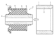
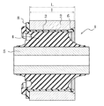
図1は、この発明に係る構造の実現工程を、そして図2は、この発明の実施の形態をそれぞれ示す、中心軸線を含む断面図である。
図中1は、ブッシュタイプの防振装置を、2はブッシュタイプの防振装置1を圧入される、剛性のスリーブをそれぞれ示す。
FIG. 1 is a cross-sectional view including a central axis showing a process for realizing the structure according to the present invention, and FIG. 2 showing an embodiment of the present invention.
In the figure,
ここで、図示の防振装置1は、合成樹脂製の外筒3と、この外筒3の内周面に、加硫接着、接着剤接着その他によって接合させた筒状の弾性体、たとえばゴム弾性体4とを具える他、このゴム弾性体4のさらに内周面に接合させて設けた剛性の内筒5を具えてなる。
Here, the
この防振装置1は、それを、自動車のリアサスペンションアーム、トレーリングアーム、トルクロッド等に取り付けられた剛性スリーブ2の貫通穴内へ、合成樹脂製の外筒3およびゴム弾性体4の縮径変形下で圧入されて、図2に示すような態様の下で使用に供される。
The
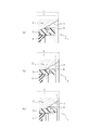
そしてここでは、外筒3の、スリーブ2への圧入長さlを、スリーブ2の軸線方向長さLより短かくして、外筒3の、圧入方向の先端部分の、スリーブ2からの突出を防止し、さらに、その外筒3の、圧入方向の先端外周面に、図3に部分拡大断面図で示すように、半径方向外方へ突出させて形成されて、外筒3の周方向に延びる、たとえば円環状の一条の突条6を設け、この突条6を、外筒3の縮径下でのスリーブ2への圧入に基づく、外筒3に固有の弾性復元力により、スリーブ2の端部分に形成されて、スリーブ2の端縁側に向けて穴径を次第に増加する、たとえば截頭円錐面の拡径表面7に、半径方向外向きの弾性押圧力の作用下で当接させえる。
And here, the press-fitting length l of the
ここで、突条6のこの半径方向外向きの弾性押圧力は、外筒3の先端外周面に半径方向外方へ突出形成された突条6が、防振装置1の、スリーブ2への圧入に伴って、スリーブ2の、均一内径の貫通穴内を縮径姿勢で通過して、その貫通穴壁面による、突条6への拘束力が解除されることによって発生し、この弾性押圧力は、突条6の突出高さ、拡径表面7の拡開形態等との関連の下で、外筒3の残部が、スリーブ2による縮径外力を受けていてなお、十分大きく確保することができる。
Here, the radially outward elastic pressing force of the
なお、図3に示すところでは、スリーブ2の拡径表面7を、所要の勾配をもつ截頭円錐面としているも、この拡径表面7は、防振装置1の中心軸線を含む断面内で、その中心軸線側に凸もしくは凹となる曲線の回転体形状とすることもできる。
In FIG. 3, the
また、図3に示すところでは、外筒3上の突条6の圧入方向の先端面をも、外筒3の先端側に向けて漸次小径となる截頭円錐面とし、その突畳の頂面を、一定外径の平坦円環面とし、そして、突条6の圧入方向後端面を、中心軸線を含む断面内で、その中心軸線側に凹となる曲線の回転体形状としているが、突条6の先端面は、中心軸線を含む断面内で、中心軸線側へ凸もしくは凹となる曲線からなるものとし、また、突条6の頂面を、同様の断面内で、曲線、一方側へ傾斜する直線、もしくは折線からなるものとし、そして、突条6の後端面を、同様の断面内で、図に示すところとは逆方向に曲がる曲線もしくは、後端側に向けて直径を減じる方向に傾斜する直線からなるものとすることもできる。
In addition, as shown in FIG. 3, the front end surface of the
ここにおいて、突条6の頂面形状は、拡径表面7の形成態様との関連において、拡径表面7に線接触する形態とすることができる他、その拡径表面7に面接触する形態とすることもできる。
前者によるときは、突条6および拡径表面7等の多少の加工誤差の有無のいかんにかかわらず、突条6をもって、拡径表面7を確実に弾性押圧することができ、また、後者によるときは、大きな押圧力の作用下で、外筒3をより効果的に抜け止めすることができる。
なおこの抜け止めに関しては、突条6および拡径表面7のそれぞれを、拡径表面7をもって突条7を包み込むような形態を選択した場合により顕著なものとなる。
Here, the shape of the top surface of the
When the former is used, the
In addition, regarding this retaining, the
ところで図3(a)に示す状態は、突条6および拡径表面7等のいずれにも加工誤差等がなく、突条6が拡径表面7の所定の位置に適正に弾性接触している状態を示し、図3(b)は、加工誤差等に起因して、突条6が、図3(a)に示すところに比して、拡径表面7の小径部側に弾性接触し、そして、図3(c)は逆に、突条6が、図3(a)に示すところに比して、拡径表面7の大径部側に弾性接触している状態をそれぞれ示す。
By the way, in the state shown in FIG. 3A, there is no processing error or the like in any of the
これらのいずれの場合にも、突条6を、半径方向外向きの弾性復元力に基いて、拡径表面7に、十分な押圧力で弾性接触させることにより、加工誤差等に起因する、外筒3とスリーブ2との間の半径方向および軸線方向のがたつきの発生を十分に防止することができ、また、突条6の、拡径表面7への弾性接触下で、突条6に、外筒3の抜け止め機能を十分に発揮させることができる。
In any of these cases, the
ここにおいて、外筒3の圧入方向の後端に、図1、2に示すように、スリーブ2の後端面に当接して、外筒3の圧入限界位置を特定する外向きフランジ8を設けた場合は、この外向きフランジ8と、上述した突起6との協働下で、スリーブ2内へ圧入した防振装置1、より直接的には外筒3を一層効果的に抜け止めすることができる。
Here, at the rear end of the
1 防振装置
2 スリーブ
3 外筒
4 ゴム弾性体
5 内筒
6 突条
7 拡径表面
l 圧入長さ
L スリーブの軸線方向長さ
DESCRIPTION OF
Claims (6)
合成樹脂製の外筒の、スリーブへの圧入長さを、スリーブの軸線方向長さより短かくするとともに、その外筒の、圧入方向の先端外周面に、半径方向外方へ突出させて形成されて、外筒の周方向に延びる突条を、スリーブの端部分に形成されて、スリーブの端縁側に向けて穴径を次第に増加する截頭円錐面としてなる拡径表面に、半径方向外向きの弾性復元力の作用下で弾性的に接触させてなる防振装置のスリーブ嵌合構造。 A vibration isolator comprising an outer cylinder and a cylindrical elastic body joined to the inner peripheral surface of the outer cylinder is press-fitted into the sleeve while the outer cylinder is reduced in diameter, and the outer peripheral surface of the outer cylinder is sleeved. A sleeve fitting structure of a vibration isolator formed by friction engagement with the inner peripheral surface of
The outer cylinder made of synthetic resin has a press-fit length to the sleeve shorter than the axial length of the sleeve, and is formed by projecting radially outward on the outer peripheral surface of the outer cylinder in the press-fit direction. A radially extending ridge extending in the circumferential direction of the outer cylinder is formed on the diameter- enlarging surface formed on the end portion of the sleeve and gradually increasing the hole diameter toward the edge of the sleeve. The sleeve fitting structure of the vibration isolator which is made to contact elastically under the action of the elastic restoring force.
Priority Applications (1)
| Application Number | Priority Date | Filing Date | Title |
|---|---|---|---|
| JP2008117631A JP5291981B2 (en) | 2008-04-28 | 2008-04-28 | Sleeve fitting structure of vibration isolator |
Applications Claiming Priority (1)
| Application Number | Priority Date | Filing Date | Title |
|---|---|---|---|
| JP2008117631A JP5291981B2 (en) | 2008-04-28 | 2008-04-28 | Sleeve fitting structure of vibration isolator |
Publications (2)
| Publication Number | Publication Date |
|---|---|
| JP2009264555A JP2009264555A (en) | 2009-11-12 |
| JP5291981B2 true JP5291981B2 (en) | 2013-09-18 |
Family
ID=41390638
Family Applications (1)
| Application Number | Title | Priority Date | Filing Date |
|---|---|---|---|
| JP2008117631A Active JP5291981B2 (en) | 2008-04-28 | 2008-04-28 | Sleeve fitting structure of vibration isolator |
Country Status (1)
| Country | Link |
|---|---|
| JP (1) | JP5291981B2 (en) |
Cited By (1)
| Publication number | Priority date | Publication date | Assignee | Title |
|---|---|---|---|---|
| WO2022229527A1 (en) | 2021-04-29 | 2022-11-03 | Psa Automobiles Sa | Rear impact-fusible rear end wedge device for increasing the compressibility efficiency of the structure |
Families Citing this family (2)
| Publication number | Priority date | Publication date | Assignee | Title |
|---|---|---|---|---|
| JP5572414B2 (en) * | 2010-02-04 | 2014-08-13 | 株式会社ブリヂストン | Anti-vibration device manufacturing method |
| JP5707113B2 (en) * | 2010-12-02 | 2015-04-22 | 株式会社ブリヂストン | Vibration isolator |
Family Cites Families (6)
| Publication number | Priority date | Publication date | Assignee | Title |
|---|---|---|---|---|
| JPH0577637U (en) * | 1992-03-23 | 1993-10-22 | 東海ゴム工業株式会社 | bush |
| JPH0741090U (en) * | 1993-12-22 | 1995-07-21 | 豊生ブレーキ工業株式会社 | Body mount |
| JP2001074080A (en) * | 1999-09-07 | 2001-03-23 | Toyo Tire & Rubber Co Ltd | Elastic bush and its assembly body |
| JP3731488B2 (en) * | 2001-03-22 | 2006-01-05 | 東海ゴム工業株式会社 | Vibration isolator |
| JP4016836B2 (en) * | 2002-12-27 | 2007-12-05 | 東海ゴム工業株式会社 | Cylindrical vibration isolator |
| JP3767545B2 (en) * | 2002-11-26 | 2006-04-19 | 東海ゴム工業株式会社 | Cylindrical vibration isolator |
-
2008
- 2008-04-28 JP JP2008117631A patent/JP5291981B2/en active Active
Cited By (2)
| Publication number | Priority date | Publication date | Assignee | Title |
|---|---|---|---|---|
| WO2022229527A1 (en) | 2021-04-29 | 2022-11-03 | Psa Automobiles Sa | Rear impact-fusible rear end wedge device for increasing the compressibility efficiency of the structure |
| FR3122356A1 (en) | 2021-04-29 | 2022-11-04 | Psa Automobiles Sa | Rear axle CALE fuse device in the event of a rear impact to increase the structure's compressibility efficiency. |
Also Published As
| Publication number | Publication date |
|---|---|
| JP2009264555A (en) | 2009-11-12 |
Similar Documents
| Publication | Publication Date | Title |
|---|---|---|
| JP2006144972A (en) | Vibration absorbing bush installation structure | |
| JP5665259B2 (en) | Soft member mounting structure | |
| JP6343535B2 (en) | Cylindrical vibration isolator | |
| EP2143972B1 (en) | Bump stopper | |
| JP5291981B2 (en) | Sleeve fitting structure of vibration isolator | |
| JP4046010B2 (en) | Dynamic damper | |
| EP1035352A3 (en) | Vibration isolator | |
| JP5964200B2 (en) | Rebound rubber | |
| JP2007176274A (en) | Stabilizer bush | |
| JP2010091014A (en) | Vibration absorbing device | |
| JP2009264568A (en) | Elastic bush | |
| JP4026609B2 (en) | Cylindrical dynamic damper | |
| JP2001295886A (en) | Vibration control device | |
| JP5084410B2 (en) | Dynamic damper for propeller shaft | |
| JP3004584B2 (en) | Elastic stopper for anti-vibration device | |
| JP7446200B2 (en) | cylinder device | |
| JP3717710B2 (en) | Spring seat rubber | |
| WO2014156495A1 (en) | Torque rod | |
| JP5184287B2 (en) | Anti-vibration bush | |
| JP2009063063A (en) | Mounting structure of dynamic damper | |
| JPH08210407A (en) | Member mount | |
| JP2001099234A (en) | Balance weight attaching structure | |
| JP2590378Y2 (en) | Dust seal for joint structures capable of swinging or spherical motion | |
| JPH06229437A (en) | Bound bumper of vehicular suspension | |
| JP3740922B2 (en) | Vibration isolator |
Legal Events
| Date | Code | Title | Description |
|---|---|---|---|
| A621 | Written request for application examination |
Free format text: JAPANESE INTERMEDIATE CODE: A621 Effective date: 20110419 |
|
| A977 | Report on retrieval |
Free format text: JAPANESE INTERMEDIATE CODE: A971007 Effective date: 20120813 |
|
| A131 | Notification of reasons for refusal |
Free format text: JAPANESE INTERMEDIATE CODE: A131 Effective date: 20121218 |
|
| A521 | Request for written amendment filed |
Free format text: JAPANESE INTERMEDIATE CODE: A523 Effective date: 20130207 |
|
| TRDD | Decision of grant or rejection written | ||
| A01 | Written decision to grant a patent or to grant a registration (utility model) |
Free format text: JAPANESE INTERMEDIATE CODE: A01 Effective date: 20130514 |
|
| A61 | First payment of annual fees (during grant procedure) |
Free format text: JAPANESE INTERMEDIATE CODE: A61 Effective date: 20130610 |
|
| R150 | Certificate of patent or registration of utility model |
Ref document number: 5291981 Country of ref document: JP Free format text: JAPANESE INTERMEDIATE CODE: R150 |
|
| R250 | Receipt of annual fees |
Free format text: JAPANESE INTERMEDIATE CODE: R250 |
|
| R250 | Receipt of annual fees |
Free format text: JAPANESE INTERMEDIATE CODE: R250 |
|
| R250 | Receipt of annual fees |
Free format text: JAPANESE INTERMEDIATE CODE: R250 |
|
| R250 | Receipt of annual fees |
Free format text: JAPANESE INTERMEDIATE CODE: R250 |
|
| R250 | Receipt of annual fees |
Free format text: JAPANESE INTERMEDIATE CODE: R250 |
|
| R250 | Receipt of annual fees |
Free format text: JAPANESE INTERMEDIATE CODE: R250 |
|
| R250 | Receipt of annual fees |
Free format text: JAPANESE INTERMEDIATE CODE: R250 |
|
| S111 | Request for change of ownership or part of ownership |
Free format text: JAPANESE INTERMEDIATE CODE: R313111 |
|
| S531 | Written request for registration of change of domicile |
Free format text: JAPANESE INTERMEDIATE CODE: R313531 |
|
| R350 | Written notification of registration of transfer |
Free format text: JAPANESE INTERMEDIATE CODE: R350 |
|
| R250 | Receipt of annual fees |
Free format text: JAPANESE INTERMEDIATE CODE: R250 |