JP5161925B2 - 分断装置 - Google Patents
分断装置 Download PDFInfo
- Publication number
- JP5161925B2 JP5161925B2 JP2010153350A JP2010153350A JP5161925B2 JP 5161925 B2 JP5161925 B2 JP 5161925B2 JP 2010153350 A JP2010153350 A JP 2010153350A JP 2010153350 A JP2010153350 A JP 2010153350A JP 5161925 B2 JP5161925 B2 JP 5161925B2
- Authority
- JP
- Japan
- Prior art keywords
- substrate
- scribe line
- break bar
- brittle material
- pressing member
- Prior art date
- Legal status (The legal status is an assumption and is not a legal conclusion. Google has not performed a legal analysis and makes no representation as to the accuracy of the status listed.)
- Expired - Fee Related
Links
- 238000005520 cutting process Methods 0.000 title claims description 20
- 239000000758 substrate Substances 0.000 claims description 77
- 239000000463 material Substances 0.000 claims description 32
- 238000003825 pressing Methods 0.000 claims description 27
- 230000009191 jumping Effects 0.000 claims description 2
- 238000000034 method Methods 0.000 description 15
- 230000007246 mechanism Effects 0.000 description 9
- 238000005452 bending Methods 0.000 description 8
- 238000013001 point bending Methods 0.000 description 8
- 239000002313 adhesive film Substances 0.000 description 6
- XUIMIQQOPSSXEZ-UHFFFAOYSA-N Silicon Chemical compound [Si] XUIMIQQOPSSXEZ-UHFFFAOYSA-N 0.000 description 3
- 239000000919 ceramic Substances 0.000 description 3
- 230000002950 deficient Effects 0.000 description 3
- 230000000694 effects Effects 0.000 description 3
- 239000011521 glass Substances 0.000 description 3
- 239000002184 metal Substances 0.000 description 3
- 239000010703 silicon Substances 0.000 description 3
- 229910052710 silicon Inorganic materials 0.000 description 3
- 238000001179 sorption measurement Methods 0.000 description 3
- 229920001875 Ebonite Polymers 0.000 description 2
- 150000001875 compounds Chemical class 0.000 description 2
- 239000006063 cullet Substances 0.000 description 2
- 239000004065 semiconductor Substances 0.000 description 2
- 230000015572 biosynthetic process Effects 0.000 description 1
- 239000002826 coolant Substances 0.000 description 1
- 238000001816 cooling Methods 0.000 description 1
- 239000013013 elastic material Substances 0.000 description 1
- 238000003384 imaging method Methods 0.000 description 1
- 230000003287 optical effect Effects 0.000 description 1
- 238000012805 post-processing Methods 0.000 description 1
- 230000008646 thermal stress Effects 0.000 description 1
- 230000007723 transport mechanism Effects 0.000 description 1
Images


Landscapes
- Liquid Crystal (AREA)
- Processing Of Stones Or Stones Resemblance Materials (AREA)
- Re-Forming, After-Treatment, Cutting And Transporting Of Glass Products (AREA)
- Dicing (AREA)
Description
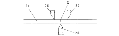
図11は板状のブレイクバーを用いた一般的な3点曲げ方式によるブレイク方式を示すものである。基板21の分断すべきスクライブラインSを跨いでその左右位置に一対の上部ブレイクバー25,25を配置し、スクライブラインSを設けた面とは反対側の面でスクライブラインSの直下に下部ブレイクバー26を配置し、上下ブレイクバーの何れか一方を基板21に押圧することによって、曲げモーメントを生じさせて分断している。
このブレイクバーによる3点曲げ方式で分断する方法は、例えば特許文献2でも開示されている。なお、ブレイクバーに代えて、ローラを用いた押圧による3点曲げ方式で分断する手段も特許文献1の図3に開示されている。
そこで本発明は、3点曲げ方式によって脆性材料基板を分断するものでありながら、分断の際に欠けや破損が生じにくくきれいな分断面を得ることのできる新規な分断装置を提供することを目的とする。
これにより、分断の際に大きな衝撃が加わることで分断端縁角部に欠けや破損が生じることを防止してきれいな分断面を得ることができるとともに、破片屑の飛散による不良品の発生を抑制することができるといった優れた効果がある。
また、脆性材料基板は吸着テーブルによって吸着固定されるので、下部ブレイクバーが基板を突き上げた際に基板がずれることがなく、正確にスクライブラインに沿って分断することができるといった効果がある。
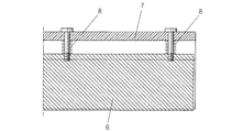
本発明において、弾性押さえ部材の先端を、幅をもたせた平面に形成して、スクライブラインの上面近傍を面接触で接するようにするのがよい。
これにより、分断の際に分断端縁を余裕をもって弾接し、上方への跳ね上がりを確実になくすことができる。
また、スプリングを省略して弾性押さえ部材全体若しくは少なくともその一部を、弾力性を有する材料で形成するようにしてもよい。
これにより、構成の簡略化とコストの低減化を図ることができる。
これにより、吸着テーブル上に脆性材料基板を載置する際の邪魔にならず、かつ、基板を載置する際にダイシングフレームなどが当接して下部ブレイクバーを傷つけることを未然に防止することができる。
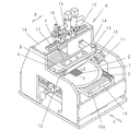
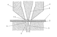
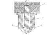
ブレイク機構Bは、分断すべきLTCC基板1の上方に配置された左右一対の上部ブレイクバー4と、LTCC基板1の下方に配置された下部ブレイクバー5と、LTCC基板1の上方で上部ブレイクバー4の間の中心に配置された弾性押さえ部材6とから構成される。
上部ブレイクバー4、下部ブレイクバー5並びに弾性押さえ部材6は何れもX方向に延びる帯状の板材で形成され、先端部を細くしてある。またその材質は金属等の硬質材で作られている。
なお、上記下部ブレイクバー5の昇降、並びに上部ブレイクバー4と弾性押さえ部材6を保持するホルダー部材7の昇降は、駆動機構(図示外)により行われる。
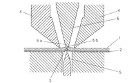
この分断の際、スクライブラインSの上面部分は弾性押さえ部材6によって弾力的に押さえられているので、LTCC基板1の分断端縁が上方に弾かれることがなく、分断端縁角部に欠けや破損が生じることを未然に防止することができる。また、分断の際、LTCC基板1は吸着テーブル10の吸引孔10aによって強く吸着固定されるので、下部ブレイクバー5がLTCC基板1を突き上げた際に基板1がずれることがなく、正確にスクライブラインに沿って分断することができる。
その他本発明では、その目的を達成し、請求の範囲を逸脱しない範囲内で適宜修正、変更することが可能である。
B ブレイク機構
S スクライブライン
1 LTCC基板(脆性材料基板)
2 粘着フイルム
3 ダイシングフレーム
4 上部ブレイクバー
5 下部ブレイクバー
6 弾性押さえ部材
7 ホルダー部材
8 スプリング
9 開口部
10 吸着テーブル
Claims (5)
- 表面にスクライブラインが形成された脆性材料基板を載置して吸着保持する吸着テーブルと、
スクライブラインの上方でその左右近傍に跨がるように配置され、脆性材料基板の表面を押さえる左右一対の上部ブレイクバーと、
スクライブラインの直下に配置され、脆性材料基板をスクライブラインの直下から突き上げて脆性材料基板を分断するための下部ブレイクバーと、
上部ブレイクバーとは別に、スクライブラインの直上全体にわたって配置され、脆性材料基板が分断された際に分断端縁部分を弾力的に押圧して上方への跳ね上がりを阻止する弾性押さえ部材とからなる分断装置。 - 弾性押さえ部材の先端を、幅をもたせた平面に形成して、スクライブラインの上面近傍を面接触で接するようにした請求項1に記載の分断装置。
- 前記弾性押さえ部材は硬質材で形成され、スプリングにより脆性材料基板に向かって付勢されている構成とした請求項1に記載の分断装置。
- 前記弾性押さえ部材は、少なくともその一部が弾力性を有する材料で形成されている請求項1に記載の分断装置。
- 前記吸着テーブルに、基板載置面に向かって開口する開口部を設け、この開口部に前記下部ブレイクバーを移動可能に配置するとともに、ブレイク時以外は下部ブレイクバーを開口部内に収めるように形成した請求項1に記載の分断装置。
Priority Applications (4)
| Application Number | Priority Date | Filing Date | Title |
|---|---|---|---|
| JP2010153350A JP5161925B2 (ja) | 2010-07-05 | 2010-07-05 | 分断装置 |
| TW100120842A TWI529790B (zh) | 2010-07-05 | 2011-06-15 | Breaking device |
| KR1020110065622A KR101278056B1 (ko) | 2010-07-05 | 2011-07-01 | 분단 장치 |
| CN201110192261.4A CN102329075B (zh) | 2010-07-05 | 2011-07-04 | 分断装置 |
Applications Claiming Priority (1)
| Application Number | Priority Date | Filing Date | Title |
|---|---|---|---|
| JP2010153350A JP5161925B2 (ja) | 2010-07-05 | 2010-07-05 | 分断装置 |
Publications (2)
| Publication Number | Publication Date |
|---|---|
| JP2012011755A JP2012011755A (ja) | 2012-01-19 |
| JP5161925B2 true JP5161925B2 (ja) | 2013-03-13 |
Family
ID=45598741
Family Applications (1)
| Application Number | Title | Priority Date | Filing Date |
|---|---|---|---|
| JP2010153350A Expired - Fee Related JP5161925B2 (ja) | 2010-07-05 | 2010-07-05 | 分断装置 |
Country Status (1)
| Country | Link |
|---|---|
| JP (1) | JP5161925B2 (ja) |
Families Citing this family (1)
| Publication number | Priority date | Publication date | Assignee | Title |
|---|---|---|---|---|
| EP2796551A4 (en) | 2011-12-21 | 2015-06-17 | Toyo Boseki | diaphorase |
Family Cites Families (7)
| Publication number | Priority date | Publication date | Assignee | Title |
|---|---|---|---|---|
| AT399865B (de) * | 1990-05-15 | 1995-08-25 | Lisec Peter | Verfahren und vorrichtung zum brechen von glasscheiben |
| JPH06171967A (ja) * | 1992-12-01 | 1994-06-21 | Toppan Printing Co Ltd | ガラス基板断裁装置 |
| JP3368246B2 (ja) * | 2000-02-23 | 2003-01-20 | 株式会社白井▲鉄▼工所 | 液晶パネルの折割装置 |
| DE10205320B4 (de) * | 2002-02-08 | 2007-12-06 | Hegla Fahrzeug- Und Maschinenbau Gmbh & Co Kg | Verfahren zum Brechen von Glasplatten |
| WO2005044744A1 (de) * | 2003-11-06 | 2005-05-19 | Peter Lisec | Verfahren und vorrichtung zum brechen geritzter glastafeln |
| JP4742649B2 (ja) * | 2005-04-05 | 2011-08-10 | ソニー株式会社 | 貼り合わせ基板の基板ブレイク装置及びその基板ブレイク方法 |
| JP5216522B2 (ja) * | 2008-10-07 | 2013-06-19 | 三星ダイヤモンド工業株式会社 | 脆性材料プライヤ |
-
2010
- 2010-07-05 JP JP2010153350A patent/JP5161925B2/ja not_active Expired - Fee Related
Also Published As
| Publication number | Publication date |
|---|---|
| JP2012011755A (ja) | 2012-01-19 |
Similar Documents
| Publication | Publication Date | Title |
|---|---|---|
| JP5216040B2 (ja) | 脆性材料基板の分断方法 | |
| KR101278056B1 (ko) | 분단 장치 | |
| JP4909657B2 (ja) | サファイア基板の加工方法 | |
| JP5824365B2 (ja) | 脆性材料基板のブレイク方法 | |
| JP2009525601A (ja) | ウェハ個片切断用支持体 | |
| JP5210409B2 (ja) | ブレイク装置 | |
| JP2014083821A (ja) | 脆性材料基板の分断方法並びに分断装置 | |
| JP5161926B2 (ja) | 分断装置 | |
| JP2004111946A (ja) | レーザーダイシング装置及びダイシング方法 | |
| JP2007134454A (ja) | 半導体装置の製造方法 | |
| KR102379114B1 (ko) | 디바이스 칩의 제조 방법 | |
| JP2010092992A (ja) | テープ伸長装置 | |
| JP2011060985A (ja) | 電子部品の製造方法 | |
| TWI842825B (zh) | 晶圓之裂斷方法 | |
| JP5161927B2 (ja) | 分断装置 | |
| JP5161925B2 (ja) | 分断装置 | |
| JP5161928B2 (ja) | 分断装置 | |
| KR20150044374A (ko) | 탄성 지지판, 파단장치 및 분단방법 | |
| KR20160029677A (ko) | 보호 테이프 박리 방법 및 보호 테이프 박리 장치 | |
| JP5800681B2 (ja) | 環状凸部除去装置 | |
| JP2010040727A (ja) | 板状物の分割方法 | |
| JP2015166190A (ja) | 脆性材料基板のブレイク装置 | |
| JPH11138523A (ja) | スクライブ装置及び基板のスクライブ方法 | |
| JP2005109061A (ja) | 半導体装置製造用治具、治具の製造方法及び半導体装置の製造方法 | |
| JPH0555373A (ja) | ウエハクラツキング方法およびその装置 |
Legal Events
| Date | Code | Title | Description |
|---|---|---|---|
| A131 | Notification of reasons for refusal |
Free format text: JAPANESE INTERMEDIATE CODE: A131 Effective date: 20120313 |
|
| A521 | Written amendment |
Free format text: JAPANESE INTERMEDIATE CODE: A523 Effective date: 20120511 |
|
| A131 | Notification of reasons for refusal |
Free format text: JAPANESE INTERMEDIATE CODE: A131 Effective date: 20120828 |
|
| A521 | Written amendment |
Free format text: JAPANESE INTERMEDIATE CODE: A523 Effective date: 20121026 |
|
| TRDD | Decision of grant or rejection written | ||
| A01 | Written decision to grant a patent or to grant a registration (utility model) |
Free format text: JAPANESE INTERMEDIATE CODE: A01 Effective date: 20121120 |
|
| A61 | First payment of annual fees (during grant procedure) |
Free format text: JAPANESE INTERMEDIATE CODE: A61 Effective date: 20121214 |
|
| R150 | Certificate of patent (=grant) or registration of utility model |
Free format text: JAPANESE INTERMEDIATE CODE: R150 |
|
| FPAY | Renewal fee payment (event date is renewal date of database) |
Free format text: PAYMENT UNTIL: 20151221 Year of fee payment: 3 |
|
| LAPS | Cancellation because of no payment of annual fees |