JP5147367B2 - エンコーダ - Google Patents
エンコーダ Download PDFInfo
- Publication number
- JP5147367B2 JP5147367B2 JP2007299738A JP2007299738A JP5147367B2 JP 5147367 B2 JP5147367 B2 JP 5147367B2 JP 2007299738 A JP2007299738 A JP 2007299738A JP 2007299738 A JP2007299738 A JP 2007299738A JP 5147367 B2 JP5147367 B2 JP 5147367B2
- Authority
- JP
- Japan
- Prior art keywords
- scanning
- scanning unit
- structural element
- encoder
- scale
- Prior art date
- Legal status (The legal status is an assumption and is not a legal conclusion. Google has not performed a legal analysis and makes no representation as to the accuracy of the status listed.)
- Active
Links
- 230000003287 optical effect Effects 0.000 claims description 78
- 238000003384 imaging method Methods 0.000 claims description 44
- 230000007935 neutral effect Effects 0.000 claims description 40
- 238000001514 detection method Methods 0.000 claims description 25
- 238000005259 measurement Methods 0.000 claims description 18
- 238000012937 correction Methods 0.000 claims description 12
- 230000000737 periodic effect Effects 0.000 claims description 11
- 230000008878 coupling Effects 0.000 claims description 6
- 238000010168 coupling process Methods 0.000 claims description 6
- 238000005859 coupling reaction Methods 0.000 claims description 6
- 230000004907 flux Effects 0.000 claims description 5
- 230000008901 benefit Effects 0.000 description 5
- 230000006870 function Effects 0.000 description 4
- 230000007274 generation of a signal involved in cell-cell signaling Effects 0.000 description 4
- 238000006073 displacement reaction Methods 0.000 description 3
- 238000000034 method Methods 0.000 description 3
- 230000008859 change Effects 0.000 description 2
- 230000000694 effects Effects 0.000 description 2
- 238000005286 illumination Methods 0.000 description 2
- 238000004519 manufacturing process Methods 0.000 description 2
- 230000010363 phase shift Effects 0.000 description 2
- 238000012545 processing Methods 0.000 description 2
- 230000009471 action Effects 0.000 description 1
- 238000003491 array Methods 0.000 description 1
- 125000004122 cyclic group Chemical group 0.000 description 1
- 230000001419 dependent effect Effects 0.000 description 1
- 238000010586 diagram Methods 0.000 description 1
- 230000008030 elimination Effects 0.000 description 1
- 238000003379 elimination reaction Methods 0.000 description 1
- 230000001747 exhibiting effect Effects 0.000 description 1
- 230000002452 interceptive effect Effects 0.000 description 1
- 230000004048 modification Effects 0.000 description 1
- 238000012986 modification Methods 0.000 description 1
- 239000013307 optical fiber Substances 0.000 description 1
- 230000008569 process Effects 0.000 description 1
- 230000009131 signaling function Effects 0.000 description 1
- 239000007787 solid Substances 0.000 description 1
- 230000007704 transition Effects 0.000 description 1
Images


Classifications
-
- G—PHYSICS
- G01—MEASURING; TESTING
- G01D—MEASURING NOT SPECIALLY ADAPTED FOR A SPECIFIC VARIABLE; ARRANGEMENTS FOR MEASURING TWO OR MORE VARIABLES NOT COVERED IN A SINGLE OTHER SUBCLASS; TARIFF METERING APPARATUS; MEASURING OR TESTING NOT OTHERWISE PROVIDED FOR
- G01D5/00—Mechanical means for transferring the output of a sensing member; Means for converting the output of a sensing member to another variable where the form or nature of the sensing member does not constrain the means for converting; Transducers not specially adapted for a specific variable
- G01D5/26—Mechanical means for transferring the output of a sensing member; Means for converting the output of a sensing member to another variable where the form or nature of the sensing member does not constrain the means for converting; Transducers not specially adapted for a specific variable characterised by optical transfer means, i.e. using infrared, visible, or ultraviolet light
- G01D5/32—Mechanical means for transferring the output of a sensing member; Means for converting the output of a sensing member to another variable where the form or nature of the sensing member does not constrain the means for converting; Transducers not specially adapted for a specific variable characterised by optical transfer means, i.e. using infrared, visible, or ultraviolet light with attenuation or whole or partial obturation of beams of light
- G01D5/34—Mechanical means for transferring the output of a sensing member; Means for converting the output of a sensing member to another variable where the form or nature of the sensing member does not constrain the means for converting; Transducers not specially adapted for a specific variable characterised by optical transfer means, i.e. using infrared, visible, or ultraviolet light with attenuation or whole or partial obturation of beams of light the beams of light being detected by photocells
- G01D5/36—Forming the light into pulses
- G01D5/38—Forming the light into pulses by diffraction gratings
-
- G—PHYSICS
- G01—MEASURING; TESTING
- G01D—MEASURING NOT SPECIALLY ADAPTED FOR A SPECIFIC VARIABLE; ARRANGEMENTS FOR MEASURING TWO OR MORE VARIABLES NOT COVERED IN A SINGLE OTHER SUBCLASS; TARIFF METERING APPARATUS; MEASURING OR TESTING NOT OTHERWISE PROVIDED FOR
- G01D5/00—Mechanical means for transferring the output of a sensing member; Means for converting the output of a sensing member to another variable where the form or nature of the sensing member does not constrain the means for converting; Transducers not specially adapted for a specific variable
- G01D5/12—Mechanical means for transferring the output of a sensing member; Means for converting the output of a sensing member to another variable where the form or nature of the sensing member does not constrain the means for converting; Transducers not specially adapted for a specific variable using electric or magnetic means
- G01D5/244—Mechanical means for transferring the output of a sensing member; Means for converting the output of a sensing member to another variable where the form or nature of the sensing member does not constrain the means for converting; Transducers not specially adapted for a specific variable using electric or magnetic means influencing characteristics of pulses or pulse trains; generating pulses or pulse trains
- G01D5/24428—Error prevention
- G01D5/24433—Error prevention by mechanical means
- G01D5/24438—Special design of the sensing element or scale
-
- G—PHYSICS
- G01—MEASURING; TESTING
- G01D—MEASURING NOT SPECIALLY ADAPTED FOR A SPECIFIC VARIABLE; ARRANGEMENTS FOR MEASURING TWO OR MORE VARIABLES NOT COVERED IN A SINGLE OTHER SUBCLASS; TARIFF METERING APPARATUS; MEASURING OR TESTING NOT OTHERWISE PROVIDED FOR
- G01D5/00—Mechanical means for transferring the output of a sensing member; Means for converting the output of a sensing member to another variable where the form or nature of the sensing member does not constrain the means for converting; Transducers not specially adapted for a specific variable
- G01D5/12—Mechanical means for transferring the output of a sensing member; Means for converting the output of a sensing member to another variable where the form or nature of the sensing member does not constrain the means for converting; Transducers not specially adapted for a specific variable using electric or magnetic means
- G01D5/244—Mechanical means for transferring the output of a sensing member; Means for converting the output of a sensing member to another variable where the form or nature of the sensing member does not constrain the means for converting; Transducers not specially adapted for a specific variable using electric or magnetic means influencing characteristics of pulses or pulse trains; generating pulses or pulse trains
- G01D5/245—Mechanical means for transferring the output of a sensing member; Means for converting the output of a sensing member to another variable where the form or nature of the sensing member does not constrain the means for converting; Transducers not specially adapted for a specific variable using electric or magnetic means influencing characteristics of pulses or pulse trains; generating pulses or pulse trains using a variable number of pulses in a train
- G01D5/2454—Encoders incorporating incremental and absolute signals
- G01D5/2455—Encoders incorporating incremental and absolute signals with incremental and absolute tracks on the same encoder
- G01D5/2457—Incremental encoders having reference marks
-
- G—PHYSICS
- G01—MEASURING; TESTING
- G01D—MEASURING NOT SPECIALLY ADAPTED FOR A SPECIFIC VARIABLE; ARRANGEMENTS FOR MEASURING TWO OR MORE VARIABLES NOT COVERED IN A SINGLE OTHER SUBCLASS; TARIFF METERING APPARATUS; MEASURING OR TESTING NOT OTHERWISE PROVIDED FOR
- G01D5/00—Mechanical means for transferring the output of a sensing member; Means for converting the output of a sensing member to another variable where the form or nature of the sensing member does not constrain the means for converting; Transducers not specially adapted for a specific variable
- G01D5/26—Mechanical means for transferring the output of a sensing member; Means for converting the output of a sensing member to another variable where the form or nature of the sensing member does not constrain the means for converting; Transducers not specially adapted for a specific variable characterised by optical transfer means, i.e. using infrared, visible, or ultraviolet light
- G01D5/32—Mechanical means for transferring the output of a sensing member; Means for converting the output of a sensing member to another variable where the form or nature of the sensing member does not constrain the means for converting; Transducers not specially adapted for a specific variable characterised by optical transfer means, i.e. using infrared, visible, or ultraviolet light with attenuation or whole or partial obturation of beams of light
- G01D5/34—Mechanical means for transferring the output of a sensing member; Means for converting the output of a sensing member to another variable where the form or nature of the sensing member does not constrain the means for converting; Transducers not specially adapted for a specific variable characterised by optical transfer means, i.e. using infrared, visible, or ultraviolet light with attenuation or whole or partial obturation of beams of light the beams of light being detected by photocells
- G01D5/36—Forming the light into pulses
- G01D5/366—Particular pulse shapes
Landscapes
- Physics & Mathematics (AREA)
- General Physics & Mathematics (AREA)
- Optical Transform (AREA)
- Length Measuring Devices By Optical Means (AREA)
Description
−絞り構造が、反射基準尺に面しない走査板の側面上に配置されている。これらの絞り構造は、光透過な構造/光非透過な構造として構成されていて、
−結像光学系が、反射基準尺に面した走査板の側面上に配置されている。
−反射基準尺に面しない走査板の側面上に配置されたフレネルレンズ,このフレネルレンズの焦点が、分割格子の平面内に存在し、部分光束が、この平面に当たり、この部分光束は、分割格子によって入射する光束から分割される。
−反射要素,この反射要素は、反射基準尺に面した走査板の側面上のフレネルレンズの焦点内に配置されている。
−反射基準尺に面しない走査板の側面上の互いに垂直に配置された周期的な2つの格子構造。
−2つの補助信号検出要素,これらの補助信号検出要素は、互いに差動に接続されていて、この場合、生じる差信号が、トリガー閾値を調整する補助信号として使用される。
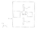
−反射基準尺に面しない走査板の側面上に配置された格子レンズ構造,この格子レンズ構造は、基準マークに相当し、この基準マークの焦点が、分割格子の平面内に存在し、部分光束が、この平面に当たり、この部分光束は、分割格子によって入射する光束から分割される。
−反射要素,この反射要素は、反射基準尺に面した走査板の側面上の格子レンズ構造の焦点内に配置されている。
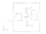
−反射基準尺に面しない走査板の側面上に配置された2つの絞り構造,
−2つの補助信号検出要素,これらの補助信号検出要素は、互いに差動に接続されていて、この場合、生じる差信号が、トリガー閾値を調整する補助信号として使用される。

x = 測定方向の座標
a1 = 基準尺平面と結像光学系との間の距離
a2 = 結像光学系と絞り面との間の距離
n = 走査板の屈折率
f = 基準マークの構造要素の焦点距離
この場合、位相関数は、結像光学系12の等高線状のこの結合光学系12の幾何学的形状を示す。
a2 = 結像光学系と絞り面との間の距離
n = 走査板の屈折率
f = 基準マークの構造要素の焦点距離
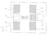
図6a中には、中立回転点Nが走査条件で明らかに基準尺平面の下に存在する事実が概略的に示されている。基準マーク31の構造要素31.1,31.2の焦点距離fが、明らかなように反射基準尺30から中立回転点Nの距離の半分に等しく選択され、結像光学系12が、この焦点距離の位置に調整される。
11 走査板
12 結像光学系
14 光源
16 コリメート光学系
17 反射要素
19 分割格子
30 反射基準尺
31 基準マーク
32 支持本体
Claims (10)
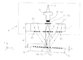
- 走査ユニット(10)及びこの走査ユニット(10)に対して少なくとも1つの測定方向(x)に移動する反射基準尺(30)を有し、少なくとも1つの基準位置(xREF)に対して1つの基準パルス信号(RI)を生成するエンコーダにおいて、
前記基準パルス信号(RI)を生成する前記走査ユニット(10)が、複数の光学要素を有し、これらの光学要素は、少なくとも1つの結合光学系(12)及びそれぞれ複数のアパーチャを含み、絞り面内に配置された少なくとも2つの絞り構造(13.1,13.2)であり、1つの光源(14)及び少なくとも2つの検出要素(15.2)が、前記走査ユニット(10)にさらに敷設されていて、
前記反射基準尺(30)は、少なくとも1つの基準位置(xREF)に対して基準マーク(31)を有し、
この基準マーク(31)は、少なくとも1組の第1構造要素(31.1)を有し、これらの第1構造要素(31.1)は、前記反射基準尺(30)の平面内に前記測定方向(x)に対して垂直に第1横周期性(T1)で周期的に配置されていて、
また、前記基準マーク(31)は、少なくとも1組の第2構造要素(31.2)を有し、これらの第2構造要素(31.2)は、前記反射基準尺(30)の平面内に前記測定方向(x)に対して垂直に第2横周期性(T2)で周期的に配置されていて、前記第1横周期性(T1)と前記第2横周期性(T2)とは互いに異なり、
これらの構造要素(31.1,31.2)は、回折構造要素として構成されていて、これらの回折構造要素は、所定の焦点距離(f)を有するシリンダレンズのように前記測定方向(x)に光学的に作用しかつ前記第1横周期性(T1)及び前記第2横周期性(T2)を有する回折格子のように前記測定方向(x)に対して垂直に作用する、当該エンコーダ。 - 前記構造要素(31.1,31.2)は、測定方向(x)に虚焦点又は実焦点を前記反射基準尺(30)から前記焦点距離(f)内に有する、請求項1に記載のエンコーダ。
- 前記構造要素(31.1,31.2)の前記焦点距離(f)は、前記反射基準尺(30)から中立回転点(N)の距離の半分に一致し、この中立回転点(N)は、位置誤差が生じることなしに、前記走査ユニット(10)又は前記反射基準尺(30)の傾きが一点の周りで可能である当該点として規定されている、請求項1に記載のエンコーダ。
- 前記構造要素(31.1,31.2)の結像側の焦点面が、前記絞り面内に結像されるように、前記走査ユニット(10)内の前記結像光学系(12)が寸法決めされている、請求項1に記載のエンコーダ。
- 前記基準マーク(31)は、それぞれ複数の組の第1構造要素(31.1)及び第2構造要素(31.2)を有し、これらの第1構造要素(31.1)及び第2構造要素(31.2)は、前記反射基準尺(30)の平面内で前記測定方向(x)に対して垂直に指向されている対称軸線(S)に対して平行に且つミラー対称に配置されていて、異なる横周期性(T1,T2)を有するそれぞれの構造要素(31.1,31.2)が、ミラー対称に対向して存在する、請求項1に記載のエンコーダ。
- 個々の前記構造要素(31.1,31.2)は、横方向(y)に平行に延在する2本の境界直線と長手方向(x)に湾曲された平行な2本の境界直線とから構成されている断面形状を有する、請求項1に記載のエンコーダ。
- 前記反射基準尺(30)は、測定方向(x)に延在する少なくとも1つの周期的なインクリメンタル目盛(33.1,33.2)をさらに有し、
前記走査ユニット(10)は、走査手段(17.1,17.2,18.1,18.2,18.3,18.4,20.1,20.2,20.3)を有し、これらの走査手段(17.1,17.2,18.1,18.2,18.3,18.4,20.1,20.2,20.3)は、反射基準尺(30)と走査ユニット(10)との相対移動時に周期的なインクリメンタル信号(INCA,INCB)を生成するために使用される、請求項1〜6のいずれか1項に記載のエンコーダ。 - 測定方向(x)に沿った両前記絞り構造(13.1,13.2)のアパーチャの位置的な配置が、前記基準マーク(31)の前記構造要素(31.1,31.2)の配置に合わせられている、請求項1〜7のいずれか1項に記載のエンコーダ。
- 前記走査ユニット(10)は、走査板(11)を有し、前記絞り構造(13.1,13.2)及び前記結像光学系(12)が、この走査板(11)上に配置されている、請求項1〜8のいずれか1項に記載のエンコーダ。
- 前記走査ユニット(110;210)は、補助信号を生成するために補正手段(126,127,128,129.1,129.2;226,227,228,229.1,229.2)を有し、これらの補助信号は、前記走査板(111;211)に対する角度の変化に対する目安を示し、前記光源(114;214)から来る光束が、この角度で前記基準マーク(131;231)の方向に伝播する、請求項1〜9のいずれか1項に記載のエンコーダ。
Applications Claiming Priority (4)
| Application Number | Priority Date | Filing Date | Title |
|---|---|---|---|
| DE102006054780.2 | 2002-11-20 | ||
| DE102006054780 | 2006-11-20 | ||
| DE102007035345.8 | 2007-07-27 | ||
| DE102007035345A DE102007035345A1 (de) | 2006-11-20 | 2007-07-27 | Positionsmesseinrichtung |
Publications (3)
| Publication Number | Publication Date |
|---|---|
| JP2008129021A JP2008129021A (ja) | 2008-06-05 |
| JP2008129021A5 JP2008129021A5 (ja) | 2010-12-09 |
| JP5147367B2 true JP5147367B2 (ja) | 2013-02-20 |
Family
ID=39031069
Family Applications (1)
| Application Number | Title | Priority Date | Filing Date |
|---|---|---|---|
| JP2007299738A Active JP5147367B2 (ja) | 2006-11-20 | 2007-11-19 | エンコーダ |
Country Status (4)
| Country | Link |
|---|---|
| US (1) | US7714273B2 (ja) |
| EP (2) | EP1923673B1 (ja) |
| JP (1) | JP5147367B2 (ja) |
| DE (1) | DE102007035345A1 (ja) |
Families Citing this family (18)
| Publication number | Priority date | Publication date | Assignee | Title |
|---|---|---|---|---|
| EP2163860B2 (en) * | 2008-09-10 | 2014-03-05 | Fagor, S.Coop. | Optoelectronic measuring device |
| DE102008059667A1 (de) | 2008-11-26 | 2010-05-27 | Dr. Johannes Heidenhain Gmbh | Positionsmesseinrichtung |
| DE102010029211A1 (de) | 2010-05-21 | 2011-11-24 | Dr. Johannes Heidenhain Gmbh | Optische Positionsmesseinrichtung |
| CN103080701B (zh) * | 2010-09-02 | 2016-05-04 | 株式会社安川电机 | 编码器、伺服马达和马达单元 |
| CN102175376B (zh) * | 2011-01-27 | 2012-06-27 | 哈尔滨工业大学 | 多光束激光外差测量微冲量的装置及方法 |
| DE102011076055A1 (de) * | 2011-05-18 | 2012-11-22 | Dr. Johannes Heidenhain Gmbh | Optische Positionsmesseinrichtung |
| DE102012204572A1 (de) | 2012-03-22 | 2013-09-26 | Dr. Johannes Heidenhain Gmbh | Positionsmesseinrichtung und Anordnung mit einer derartigen Positionsmesseinrichtung |
| DE102012021935A1 (de) | 2012-11-09 | 2014-05-15 | Dr. Johannes Heidenhain Gmbh | Optische Positionsmesseinrichtung |
| CN108324311B (zh) * | 2013-01-31 | 2022-02-11 | Ge医疗系统环球技术有限公司 | 患者身体外形自动检测和患者智能定位 |
| DE102015209716B4 (de) | 2014-05-29 | 2023-04-20 | Mitutoyo Corporation | Optischer Codierer mit anpassbarer Auflösung |
| DE102014214839A1 (de) | 2014-07-29 | 2016-02-04 | Dr. Johannes Heidenhain Gmbh | Interferometer |
| JP6517516B2 (ja) * | 2015-01-21 | 2019-05-22 | 株式会社ミツトヨ | エンコーダ |
| JP6519399B2 (ja) * | 2015-08-13 | 2019-05-29 | 富士ゼロックス株式会社 | 計測装置及びプログラム |
| DE102016200847A1 (de) * | 2016-01-21 | 2017-07-27 | Dr. Johannes Heidenhain Gesellschaft Mit Beschränkter Haftung | Optische Positionsmesseinrichtung |
| DE102017219125A1 (de) * | 2017-10-25 | 2019-04-25 | Dr. Johannes Heidenhain Gmbh | Optische Positionsmesseinrichtung |
| DE102019219151A1 (de) | 2019-12-09 | 2021-06-10 | Dr. Johannes Heidenhain Gesellschaft Mit Beschränkter Haftung | Optische Positionsmesseinrichtung |
| CN113405460B (zh) * | 2020-03-16 | 2023-04-14 | 晋城三赢精密电子有限公司 | 微位移测量装置 |
| DE102024001846A1 (de) * | 2023-07-31 | 2025-02-06 | Dr. Johannes Heidenhain Gmbh | Optische Positionsmesseinrichtung |
Family Cites Families (16)
| Publication number | Priority date | Publication date | Assignee | Title |
|---|---|---|---|---|
| DE3416864C2 (de) * | 1984-05-08 | 1986-04-10 | Dr. Johannes Heidenhain Gmbh, 8225 Traunreut | Photoelektrische Meßeinrichtung |
| JPS61182523A (ja) * | 1985-02-08 | 1986-08-15 | Mitsutoyo Mfg Co Ltd | 光電式変位検出装置 |
| DE3726678C1 (de) * | 1987-08-11 | 1989-03-09 | Heidenhain Gmbh Dr Johannes | Inkrementale Laengen- oder Winkelmesseinrichtung |
| US5073710A (en) * | 1989-09-21 | 1991-12-17 | Copal Company Limited | Optical displacement detector including a displacement member's surface having a diffractive pattern and a holographic lens pattern |
| DE8915991U1 (de) * | 1989-11-30 | 1992-10-22 | Dr. Johannes Heidenhain Gmbh, 8225 Traunreut | Lichtelektrische Positionsmeßeinrichtung |
| DE59207010D1 (de) * | 1992-06-17 | 1996-10-02 | Heidenhain Gmbh Dr Johannes | Messeinrichtung |
| JP3358286B2 (ja) * | 1994-03-31 | 2002-12-16 | ソニー・プレシジョン・テクノロジー株式会社 | 定点検出装置 |
| US6229140B1 (en) * | 1995-10-27 | 2001-05-08 | Canon Kabushiki Kaisha | Displacement information detection apparatus |
| CN1151361C (zh) * | 1996-05-20 | 2004-05-26 | 松下电器产业株式会社 | 光学编码器及位置检测方法 |
| JP3775892B2 (ja) * | 1996-05-20 | 2006-05-17 | 松下電器産業株式会社 | 光学式エンコーダ |
| DE19921309A1 (de) * | 1999-05-07 | 2000-11-09 | Heidenhain Gmbh Dr Johannes | Abtasteinheit für eine optische Positionsmeßeinrichtung |
| EP1421343A2 (en) * | 2001-08-30 | 2004-05-26 | MicroE Systems Corporation | Reference point talbot encoder |
| GB0205972D0 (en) * | 2002-03-14 | 2002-04-24 | Renishaw Plc | Encoder with reference marks |
| DE102005006247A1 (de) * | 2005-02-11 | 2006-08-17 | Dr. Johannes Heidenhain Gmbh | Positionsmesseinrichtung |
| US7858922B2 (en) * | 2006-11-20 | 2010-12-28 | Dr. Johannes Heidenhain Gmbh | Position-measuring device |
| JP5286584B2 (ja) * | 2007-06-19 | 2013-09-11 | 株式会社ミツトヨ | 絶対位置測長型エンコーダ |
-
2007
- 2007-07-27 DE DE102007035345A patent/DE102007035345A1/de not_active Withdrawn
- 2007-10-10 EP EP07019810.6A patent/EP1923673B1/de active Active
- 2007-10-10 EP EP07019809A patent/EP1923672B1/de active Active
- 2007-11-19 US US11/942,435 patent/US7714273B2/en active Active
- 2007-11-19 JP JP2007299738A patent/JP5147367B2/ja active Active
Also Published As
| Publication number | Publication date |
|---|---|
| JP2008129021A (ja) | 2008-06-05 |
| EP1923672A3 (de) | 2011-11-23 |
| US20080117440A1 (en) | 2008-05-22 |
| EP1923673B1 (de) | 2015-03-25 |
| DE102007035345A1 (de) | 2008-05-21 |
| EP1923673A2 (de) | 2008-05-21 |
| EP1923673A3 (de) | 2012-11-14 |
| EP1923672A2 (de) | 2008-05-21 |
| US7714273B2 (en) | 2010-05-11 |
| EP1923672B1 (de) | 2012-12-12 |
Similar Documents
| Publication | Publication Date | Title |
|---|---|---|
| JP5147367B2 (ja) | エンコーダ | |
| JP5147368B2 (ja) | エンコーダ | |
| JP5100266B2 (ja) | エンコーダ | |
| JP5079874B2 (ja) | 位置測定装置 | |
| US9766098B2 (en) | Optical position measuring instrument | |
| JPH11142114A (ja) | 光学位置測定装置用の走査ユニット | |
| US20060180748A1 (en) | Position measuring instrument | |
| JP4936980B2 (ja) | 光学エンコーダ | |
| JP5128368B2 (ja) | エンコーダ用のスケール及びエンコーダ | |
| JP6875923B2 (ja) | スケール装置および二軸変位検出装置 | |
| US7404259B2 (en) | Optical position measuring instrument | |
| JPH09113213A (ja) | 高調波信号成分を濾波する装置 | |
| CN113028998B (zh) | 光学位置测量装置 | |
| US10190893B2 (en) | Encoder | |
| JP6293700B2 (ja) | エンコーダ | |
| JP6525546B2 (ja) | 位置計測装置 | |
| US7705289B2 (en) | Scanning unit for an optical position-measuring device | |
| JP2009019876A (ja) | 光学式絶対値エンコーダ | |
| WO2007074752A1 (ja) | チルトセンサ及びエンコーダ | |
| JP2016130728A (ja) | 光学式位置測定装置 | |
| JPH07270121A (ja) | 位置センサ | |
| CN119437048A (zh) | 光学位置测量器 | |
| US9389100B2 (en) | Optical position measuring instrument | |
| JP2016166874A (ja) | 光学式角度測定装置 |
Legal Events
| Date | Code | Title | Description |
|---|---|---|---|
| RD04 | Notification of resignation of power of attorney |
Free format text: JAPANESE INTERMEDIATE CODE: A7424 Effective date: 20100517 |
|
| A521 | Request for written amendment filed |
Free format text: JAPANESE INTERMEDIATE CODE: A523 Effective date: 20101022 |
|
| A621 | Written request for application examination |
Free format text: JAPANESE INTERMEDIATE CODE: A621 Effective date: 20101022 |
|
| A131 | Notification of reasons for refusal |
Free format text: JAPANESE INTERMEDIATE CODE: A131 Effective date: 20120529 |
|
| A521 | Request for written amendment filed |
Free format text: JAPANESE INTERMEDIATE CODE: A523 Effective date: 20120724 |
|
| TRDD | Decision of grant or rejection written | ||
| A01 | Written decision to grant a patent or to grant a registration (utility model) |
Free format text: JAPANESE INTERMEDIATE CODE: A01 Effective date: 20121030 |
|
| A61 | First payment of annual fees (during grant procedure) |
Free format text: JAPANESE INTERMEDIATE CODE: A61 Effective date: 20121127 |
|
| R150 | Certificate of patent or registration of utility model |
Ref document number: 5147367 Country of ref document: JP Free format text: JAPANESE INTERMEDIATE CODE: R150 Free format text: JAPANESE INTERMEDIATE CODE: R150 |
|
| FPAY | Renewal fee payment (event date is renewal date of database) |
Free format text: PAYMENT UNTIL: 20151207 Year of fee payment: 3 |
|
| R250 | Receipt of annual fees |
Free format text: JAPANESE INTERMEDIATE CODE: R250 |
|
| R250 | Receipt of annual fees |
Free format text: JAPANESE INTERMEDIATE CODE: R250 |
|
| R250 | Receipt of annual fees |
Free format text: JAPANESE INTERMEDIATE CODE: R250 |
|
| R250 | Receipt of annual fees |
Free format text: JAPANESE INTERMEDIATE CODE: R250 |
|
| R250 | Receipt of annual fees |
Free format text: JAPANESE INTERMEDIATE CODE: R250 |
|
| R250 | Receipt of annual fees |
Free format text: JAPANESE INTERMEDIATE CODE: R250 |
|
| R250 | Receipt of annual fees |
Free format text: JAPANESE INTERMEDIATE CODE: R250 |
|
| R250 | Receipt of annual fees |
Free format text: JAPANESE INTERMEDIATE CODE: R250 |
|
| R250 | Receipt of annual fees |
Free format text: JAPANESE INTERMEDIATE CODE: R250 |
|
| R250 | Receipt of annual fees |
Free format text: JAPANESE INTERMEDIATE CODE: R250 |