JP5147367B2 - Encoder - Google Patents
Encoder Download PDFInfo
- Publication number
- JP5147367B2 JP5147367B2 JP2007299738A JP2007299738A JP5147367B2 JP 5147367 B2 JP5147367 B2 JP 5147367B2 JP 2007299738 A JP2007299738 A JP 2007299738A JP 2007299738 A JP2007299738 A JP 2007299738A JP 5147367 B2 JP5147367 B2 JP 5147367B2
- Authority
- JP
- Japan
- Prior art keywords
- scanning
- scanning unit
- structural element
- encoder
- scale
- Prior art date
- Legal status (The legal status is an assumption and is not a legal conclusion. Google has not performed a legal analysis and makes no representation as to the accuracy of the status listed.)
- Active
Links
- 230000003287 optical effect Effects 0.000 claims description 78
- 238000003384 imaging method Methods 0.000 claims description 44
- 230000007935 neutral effect Effects 0.000 claims description 40
- 238000001514 detection method Methods 0.000 claims description 25
- 238000005259 measurement Methods 0.000 claims description 18
- 238000012937 correction Methods 0.000 claims description 12
- 230000000737 periodic effect Effects 0.000 claims description 11
- 230000008878 coupling Effects 0.000 claims description 6
- 238000010168 coupling process Methods 0.000 claims description 6
- 238000005859 coupling reaction Methods 0.000 claims description 6
- 230000004907 flux Effects 0.000 claims description 5
- 230000008901 benefit Effects 0.000 description 5
- 230000006870 function Effects 0.000 description 4
- 230000007274 generation of a signal involved in cell-cell signaling Effects 0.000 description 4
- 238000006073 displacement reaction Methods 0.000 description 3
- 238000000034 method Methods 0.000 description 3
- 230000008859 change Effects 0.000 description 2
- 230000000694 effects Effects 0.000 description 2
- 238000005286 illumination Methods 0.000 description 2
- 238000004519 manufacturing process Methods 0.000 description 2
- 230000010363 phase shift Effects 0.000 description 2
- 238000012545 processing Methods 0.000 description 2
- 230000009471 action Effects 0.000 description 1
- 238000003491 array Methods 0.000 description 1
- 125000004122 cyclic group Chemical group 0.000 description 1
- 230000001419 dependent effect Effects 0.000 description 1
- 238000010586 diagram Methods 0.000 description 1
- 230000008030 elimination Effects 0.000 description 1
- 238000003379 elimination reaction Methods 0.000 description 1
- 230000001747 exhibiting effect Effects 0.000 description 1
- 230000002452 interceptive effect Effects 0.000 description 1
- 230000004048 modification Effects 0.000 description 1
- 238000012986 modification Methods 0.000 description 1
- 239000013307 optical fiber Substances 0.000 description 1
- 230000008569 process Effects 0.000 description 1
- 230000009131 signaling function Effects 0.000 description 1
- 239000007787 solid Substances 0.000 description 1
- 230000007704 transition Effects 0.000 description 1
Images


Classifications
-
- G—PHYSICS
- G01—MEASURING; TESTING
- G01D—MEASURING NOT SPECIALLY ADAPTED FOR A SPECIFIC VARIABLE; ARRANGEMENTS FOR MEASURING TWO OR MORE VARIABLES NOT COVERED IN A SINGLE OTHER SUBCLASS; TARIFF METERING APPARATUS; MEASURING OR TESTING NOT OTHERWISE PROVIDED FOR
- G01D5/00—Mechanical means for transferring the output of a sensing member; Means for converting the output of a sensing member to another variable where the form or nature of the sensing member does not constrain the means for converting; Transducers not specially adapted for a specific variable
- G01D5/26—Mechanical means for transferring the output of a sensing member; Means for converting the output of a sensing member to another variable where the form or nature of the sensing member does not constrain the means for converting; Transducers not specially adapted for a specific variable characterised by optical transfer means, i.e. using infrared, visible, or ultraviolet light
- G01D5/32—Mechanical means for transferring the output of a sensing member; Means for converting the output of a sensing member to another variable where the form or nature of the sensing member does not constrain the means for converting; Transducers not specially adapted for a specific variable characterised by optical transfer means, i.e. using infrared, visible, or ultraviolet light with attenuation or whole or partial obturation of beams of light
- G01D5/34—Mechanical means for transferring the output of a sensing member; Means for converting the output of a sensing member to another variable where the form or nature of the sensing member does not constrain the means for converting; Transducers not specially adapted for a specific variable characterised by optical transfer means, i.e. using infrared, visible, or ultraviolet light with attenuation or whole or partial obturation of beams of light the beams of light being detected by photocells
- G01D5/36—Forming the light into pulses
- G01D5/38—Forming the light into pulses by diffraction gratings
-
- G—PHYSICS
- G01—MEASURING; TESTING
- G01D—MEASURING NOT SPECIALLY ADAPTED FOR A SPECIFIC VARIABLE; ARRANGEMENTS FOR MEASURING TWO OR MORE VARIABLES NOT COVERED IN A SINGLE OTHER SUBCLASS; TARIFF METERING APPARATUS; MEASURING OR TESTING NOT OTHERWISE PROVIDED FOR
- G01D5/00—Mechanical means for transferring the output of a sensing member; Means for converting the output of a sensing member to another variable where the form or nature of the sensing member does not constrain the means for converting; Transducers not specially adapted for a specific variable
- G01D5/12—Mechanical means for transferring the output of a sensing member; Means for converting the output of a sensing member to another variable where the form or nature of the sensing member does not constrain the means for converting; Transducers not specially adapted for a specific variable using electric or magnetic means
- G01D5/244—Mechanical means for transferring the output of a sensing member; Means for converting the output of a sensing member to another variable where the form or nature of the sensing member does not constrain the means for converting; Transducers not specially adapted for a specific variable using electric or magnetic means influencing characteristics of pulses or pulse trains; generating pulses or pulse trains
- G01D5/24428—Error prevention
- G01D5/24433—Error prevention by mechanical means
- G01D5/24438—Special design of the sensing element or scale
-
- G—PHYSICS
- G01—MEASURING; TESTING
- G01D—MEASURING NOT SPECIALLY ADAPTED FOR A SPECIFIC VARIABLE; ARRANGEMENTS FOR MEASURING TWO OR MORE VARIABLES NOT COVERED IN A SINGLE OTHER SUBCLASS; TARIFF METERING APPARATUS; MEASURING OR TESTING NOT OTHERWISE PROVIDED FOR
- G01D5/00—Mechanical means for transferring the output of a sensing member; Means for converting the output of a sensing member to another variable where the form or nature of the sensing member does not constrain the means for converting; Transducers not specially adapted for a specific variable
- G01D5/12—Mechanical means for transferring the output of a sensing member; Means for converting the output of a sensing member to another variable where the form or nature of the sensing member does not constrain the means for converting; Transducers not specially adapted for a specific variable using electric or magnetic means
- G01D5/244—Mechanical means for transferring the output of a sensing member; Means for converting the output of a sensing member to another variable where the form or nature of the sensing member does not constrain the means for converting; Transducers not specially adapted for a specific variable using electric or magnetic means influencing characteristics of pulses or pulse trains; generating pulses or pulse trains
- G01D5/245—Mechanical means for transferring the output of a sensing member; Means for converting the output of a sensing member to another variable where the form or nature of the sensing member does not constrain the means for converting; Transducers not specially adapted for a specific variable using electric or magnetic means influencing characteristics of pulses or pulse trains; generating pulses or pulse trains using a variable number of pulses in a train
- G01D5/2454—Encoders incorporating incremental and absolute signals
- G01D5/2455—Encoders incorporating incremental and absolute signals with incremental and absolute tracks on the same encoder
- G01D5/2457—Incremental encoders having reference marks
-
- G—PHYSICS
- G01—MEASURING; TESTING
- G01D—MEASURING NOT SPECIALLY ADAPTED FOR A SPECIFIC VARIABLE; ARRANGEMENTS FOR MEASURING TWO OR MORE VARIABLES NOT COVERED IN A SINGLE OTHER SUBCLASS; TARIFF METERING APPARATUS; MEASURING OR TESTING NOT OTHERWISE PROVIDED FOR
- G01D5/00—Mechanical means for transferring the output of a sensing member; Means for converting the output of a sensing member to another variable where the form or nature of the sensing member does not constrain the means for converting; Transducers not specially adapted for a specific variable
- G01D5/26—Mechanical means for transferring the output of a sensing member; Means for converting the output of a sensing member to another variable where the form or nature of the sensing member does not constrain the means for converting; Transducers not specially adapted for a specific variable characterised by optical transfer means, i.e. using infrared, visible, or ultraviolet light
- G01D5/32—Mechanical means for transferring the output of a sensing member; Means for converting the output of a sensing member to another variable where the form or nature of the sensing member does not constrain the means for converting; Transducers not specially adapted for a specific variable characterised by optical transfer means, i.e. using infrared, visible, or ultraviolet light with attenuation or whole or partial obturation of beams of light
- G01D5/34—Mechanical means for transferring the output of a sensing member; Means for converting the output of a sensing member to another variable where the form or nature of the sensing member does not constrain the means for converting; Transducers not specially adapted for a specific variable characterised by optical transfer means, i.e. using infrared, visible, or ultraviolet light with attenuation or whole or partial obturation of beams of light the beams of light being detected by photocells
- G01D5/36—Forming the light into pulses
- G01D5/366—Particular pulse shapes
Description
本発明は、請求項1の上位概念に記載の光学エンコーダに関する。
The present invention relates to an optical encoder according to the superordinate concept of
本発明は、エンコーダに関する。 The present invention relates to an encoder.
公知のエンコーダは、相対移動する2つの物体の相対変位に関する周期的なインクリメンタル信号のほかに、いわゆる基準パルスも提供する。相対移動する両物体の位置に関する正確な絶対的な関係が、測定区間に沿った所定の基準位置でこれらの基準パルス信号によって得られる。このとき、一般に明らかに高い分解能のインクリメンタル信号が、こうして測定された絶対位置に後で適用され得る。基準パルス信号を生成するため、多くの可能性が既に公知である。これに対しては、例えば米国特許第5,073,710号明細書又は米国特許第5,981,941号明細書を参照のこと。これらの明細書はそれぞれ、光学式エンコーダに関する形態を開示する。基準パルス信号を生成するため、これらの明細書では、回折基準マーク構造がそれぞれ、基準尺面上でインクリメンタルトラックに隣接して基準位置に配置される。1つの対応する基準パルス信号が、それぞれの位置で基準マークの走査から発生する照射式に動作される特に高い分解能の光学式エンコーダの場合、特定の基準パルス信号の生成が要求される。したがって、例えば走査ユニット及び反射基準尺の最適でない取り付けによって引き起こされたこの走査ユニット及び反射基準尺の場合によっては起こりうる傾き時にも、位置誤差が可能な限り発生してはならない。この場合、このことは、インクリメンタル信号の生成及び基準パルス信号の生成の双方に対して成立する。上述した両明細書では、この問題の解決手段に関する示唆は見つからない。
本発明の課題は、基準パルス信号が走査ユニットと反射基準尺との間の場合によっては起こりうる傾きによってほとんど妨害されない、照射動作式の高分解能のエンコーダを提供することにある。 An object of the present invention is to provide an irradiation-operational high-resolution encoder in which the reference pulse signal is hardly disturbed by a possible tilt between the scanning unit and the reflective reference scale.
この課題は、請求項1に記載の特徴を有するエンコーダによって解決される。
This problem is solved by an encoder having the features of
好適な実施形は、従属請求項中に説明されている手段から得られる。 Preferred embodiments are obtained from the means described in the dependent claims.
本発明によれば、インクリメンタル信号及び基準パルス信号を生成するための走査ユニット及び反射基準尺の傾きに関して同じ挙動を提供することが提唱される。それ故に両走査に対して、両走査のいわゆる中立回転点が一致することが保証される。この場合、その都度の走査のこの中立回転点は、位置誤差が生じることなしに、走査ユニット及び反射基準尺が一点の周りで傾きうるこの点を意味する。 According to the present invention, it is proposed to provide the same behavior with respect to the tilt of the scanning unit and the reflective reference scale for generating the incremental signal and the reference pulse signal. Therefore, for both scans, it is guaranteed that the so-called neutral rotation points of both scans coincide. In this case, this neutral rotation point of each scan means this point where the scanning unit and the reflective reference scale can be tilted around one point without causing a position error.
本発明の範囲内では、特に基準パルス信号に関する適切な手段によって、基準パルス信号の生成の中立回転点の位置の所定の調整が可能であることが確認できた。これによって、基準パルス信号の生成の中立回転点が、インクリメンタル信号の生成時の中立回転点に一致され得る。インクリメンタル信号の生成の中立回転点が、このようなエンコーダの設計時に一般にその都度のシステム要求から生じる。本発明の手段によって、基準パルス信号の生成の中立回転点が、インクリメンタル信号の生成時の異なる状況に柔軟に適合できる。このことは、例えば一平面内の基準パルス信号の生成の中立回転点が反射基準尺の上又は下に存在することを意味しうる。 Within the scope of the present invention, it has been confirmed that predetermined adjustment of the position of the neutral rotation point of the generation of the reference pulse signal is possible by means appropriate for the reference pulse signal. Thereby, the neutral rotation point at which the reference pulse signal is generated can be matched with the neutral rotation point at the time of generating the incremental signal. The neutral rotation point of the incremental signal generation generally arises from the respective system requirements when designing such an encoder. By means of the invention, the neutral rotation point of the generation of the reference pulse signal can be flexibly adapted to different situations during the generation of the incremental signal. This can mean, for example, that a neutral rotation point for generating a reference pulse signal in one plane is above or below the reflection reference scale.
これに対して、走査ユニット及びこの走査ユニットに対して少なくとも1つの基準位置(x)に沿って移動する反射基準尺を有するエンコーダが、少なくとも1つの基準位置に対して1つの基準パルス信号を生成する。この走査ユニットは、基準パルス信号を生成するために多数の光学要素を有する。これらの光学要素は、少なくとも1つの結像光学系及び絞り面内に配置されたそれぞれ多数のアパーチャを有する少なくとも2つの絞り構造である。1つの光源及び少なくとも2つの検出要素が、走査ユニットに敷設されている。反射基準尺は、少なくとも1つの基準位置に対して1つの基準マークを有する。この基準マークは、少なくとも1組の構造要素を有する。これらの構造要素は、測定方向に対して垂直な反射基準尺の平面内に第1横周期性T1で周期的に配置されている。さらに基準マークは、少なくとも1組の第2構造要素を有する。これらの構造要素は、測定方向に対して垂直な反射基準尺の平面内に第2周期性T2で周期的に配置されている。第1横周期性と第2横周期性とは互いに異なる。これらの構造要素は、回折構造要素として構成されている。これらの回折構造要素は、所定の焦点距離を有するシリンダレンズのように測定方向に光学的に作用し、目盛周期T1又はT2を有する回折格子のように測定方向に対して垂直に作用する。 In contrast, an encoder having a scanning unit and a reflective reference scale moving along at least one reference position (x) relative to the scanning unit generates one reference pulse signal for at least one reference position. To do. The scanning unit has a number of optical elements for generating a reference pulse signal. These optical elements are at least two aperture structures each having at least one imaging optical system and a number of apertures arranged in the aperture plane. One light source and at least two detection elements are laid on the scanning unit. The reflective reference scale has one reference mark for at least one reference position. The reference mark has at least one set of structural elements. These structural elements are periodically arranged with a first transverse periodicity T1 in a plane of a reflection reference scale perpendicular to the measurement direction. Furthermore, the fiducial mark has at least one set of second structural elements. These structural elements are periodically arranged with the second periodicity T2 in the plane of the reflection reference scale perpendicular to the measurement direction. The first lateral periodicity and the second lateral periodicity are different from each other. These structural elements are configured as diffractive structural elements. These diffractive structural elements act optically in the measurement direction like a cylinder lens having a predetermined focal length, and act perpendicularly to the measurement direction like a diffraction grating having a graduation period T1 or T2.
構造要素は、特に測定方向に実焦点又は虚焦点を反射基準尺から焦点距離内に有する。 The structural element has a real or imaginary focus, in particular in the measuring direction, within the focal length from the reflection reference scale.
特に構造要素の焦点距離は、反射基準尺から中立回転点の距離の半分に一致する。この場合、中立回転点は、位置誤差が生じることなしに、走査ユニット又は反射基準尺の傾きが一点の周りで可能であるこの点として規定されている。 In particular, the focal length of the structural element coincides with half the distance from the reflection reference scale to the neutral rotation point. In this case, the neutral rotation point is defined as this point where the scanning unit or reflection reference scale can be tilted around one point without any positional error.
構造要素の結像側の焦点面が、絞り面内に結像されるように、結像光学系が、走査ユニット内で有利に寸法決めされている。 The imaging optics is advantageously dimensioned in the scanning unit so that the focal plane on the imaging side of the structural element is imaged in the aperture plane.
可能な実施形では、基準マークがそれぞれ、多数組の第1構造要素及び第2構造要素を有する。この場合、これらの第1構造要素及び第2構造要素は、対称軸線に対して平行に又はミラー対称に測定方向に対して垂直に基準尺内に配置されている。異なる横周期性を有するそれぞれの構造要素が、対向して存在する。 In a possible implementation, the fiducial marks each have multiple sets of first and second structural elements. In this case, these first and second structural elements are arranged in a reference scale parallel to the axis of symmetry or mirror-symmetrically and perpendicular to the measuring direction. Each structural element having a different transverse periodicity exists oppositely.
個々の構造要素が、特に断面形状を有し得る。この断面形状は、横方向に平行に延在する2本の境界直線及び長手方向に湾曲し平行な2本の境界直線から構成されている。 Individual structural elements can in particular have a cross-sectional shape. This cross-sectional shape is composed of two boundary straight lines extending in parallel in the horizontal direction and two boundary straight lines curved in parallel in the longitudinal direction.
本発明のエンコーダの可能な実施形では、反射基準尺が、測定方向に延在する少なくとも1つの周期的なインクリメンタル目盛をさらに有する。走査ユニットは、走査手段をさらに有する。この走査手段は、反射基準尺と走査ユニットとの相対移動時に周期的なインクリメンタル信号を生成するために使用される。 In a possible embodiment of the encoder according to the invention, the reflection reference scale further comprises at least one periodic incremental scale extending in the measuring direction. The scanning unit further includes scanning means. This scanning means is used to generate a periodic incremental signal during relative movement of the reflective reference scale and the scanning unit.
このようなエンコーダでは、基準パルス信号の生成の中立回転点の位置が、インクリメンタル信号の生成の中立回転点の位置に適合するように、構造要素の焦点距離が特に選択されている。この場合、中立回転点は、位置誤差が生じることなしに、走査ユニット又は反射基準尺の傾きが一点の周りで可能であるこの点として規定されている。 In such an encoder, the focal length of the structural element is particularly selected so that the position of the neutral rotation point for generating the reference pulse signal matches the position of the neutral rotation point for generating the incremental signal. In this case, the neutral rotation point is defined as this point where the scanning unit or reflection reference scale can be tilted around one point without any positional error.
本発明のエンコーダでは、測定方向(x)に沿った両絞り構造のアパーチャの位置的な配置が、基準マークの構造要素の配置に有利に合わせられている。 In the encoder according to the invention, the positional arrangement of the apertures of both diaphragm structures along the measuring direction (x) is advantageously matched to the arrangement of the structural elements of the reference mark.
結像光学系は、多数の単レンズから構成されるレンズアレイとして構成され得る。 The imaging optical system can be configured as a lens array including a large number of single lenses.
走査ユニットは、例えば走査板を有し得る。絞り構造及び結像光学系が、この走査板上に配置されている。 The scanning unit can have, for example, a scanning plate. A diaphragm structure and an imaging optical system are disposed on the scanning plate.
この場合、走査板は以下のように構成され得る:
−絞り構造が、反射基準尺に面しない走査板の側面上に配置されている。これらの絞り構造は、光透過な構造/光非透過な構造として構成されていて、
−結像光学系が、反射基準尺に面した走査板の側面上に配置されている。
In this case, the scanning plate can be configured as follows:
The diaphragm structure is arranged on the side of the scanning plate that does not face the reflective reference scale. These diaphragm structures are configured as a light transmissive structure / light non-transmissive structure,
The imaging optical system is arranged on the side of the scanning plate facing the reflection reference scale.
この代わりに走査ユニットは、走査板を有してもよい。絞り構造及び結像光学系が、反射基準尺に面した走査板の側面上に配置されていて、これらの絞り構造は、反射する構造/反射しない構造として構成されている。 Alternatively, the scanning unit may have a scanning plate. The diaphragm structure and the imaging optical system are arranged on the side surface of the scanning plate facing the reflection reference scale, and these diaphragm structures are configured as a reflective structure / non-reflective structure.
この場合、分割格子が、走査板上にさらに配置され得る。光源から来る光束が、この分割格子によって基準パルス信号の生成に利用される部分光束とインクリメンタル信号の生成に利用される部分光束とに分割される。 In this case, a dividing grid can be further arranged on the scanning plate. The light beam coming from the light source is split by this split grating into a partial light beam used for generating the reference pulse signal and a partial light beam used for generating the incremental signal.
反射基準尺上の基準マークが収束照射されるように、分割格子が構成され得る。 The split grating can be configured so that the reference marks on the reflective reference scale are convergently illuminated.
分割格子は、例えば湾曲した格子線を有する回折分光器として構成され得る。 The split grating can be configured, for example, as a diffraction spectrometer having curved grating lines.
1つ又は多数の反射要素が、反射基準尺に面しないで指向されている走査板の側面上に配置され得る。この又はこれらの反射要素は、この又はこれらの反射要素上に入射する光束を反射基準尺に面している走査板の側面方向に再び偏向させる。 One or many reflective elements may be arranged on the side of the scanning plate that is oriented without facing the reflective reference scale. This or these reflective elements again deflect the light beam incident on this or these reflective elements in the direction of the side of the scanning plate facing the reflective reference scale.
分割格子は、例えば反射基準尺に面している走査板の側面上に配置され得る。 The split grating can be arranged on the side of the scanning plate facing the reflection reference scale, for example.
本発明のエンコーダの別の実施形では、加算器及び減算器が、2つの検出要素の後方に配置されていて、それぞれ所定にプリセットされているトリガー閾値を有する多数の比較器が、同様にこれらの加算器及び減算器の後方に配置されている。生成されたインクリメンタル信号の幅に一致する幅を有する基準パルス信号が出力側で出力されるように、これらの比較器が互いに接続されている。 In another embodiment of the encoder according to the invention, an adder and a subtractor are arranged behind the two detection elements, each of which has a number of comparators, each having a preset trigger threshold. Are arranged behind the adder and subtractor. These comparators are connected to each other so that a reference pulse signal having a width that matches the width of the generated incremental signal is output on the output side.
さらに走査ユニットは、補助信号を生成する補正手段を有し得る。これらの補助信号は、走査板に対する角度の変化に対する目安を示す。光源から来る光束が、この角度で基準マークの方向に伝播する。 Furthermore, the scanning unit may have correction means for generating an auxiliary signal. These auxiliary signals indicate a measure for changes in the angle with respect to the scanning plate. The light beam coming from the light source propagates in the direction of the reference mark at this angle.
この場合、走査ユニットは、補助信号を生成する以下の補正手段を有し得る:
−反射基準尺に面しない走査板の側面上に配置されたフレネルレンズ,このフレネルレンズの焦点が、分割格子の平面内に存在し、部分光束が、この平面に当たり、この部分光束は、分割格子によって入射する光束から分割される。
−反射要素,この反射要素は、反射基準尺に面した走査板の側面上のフレネルレンズの焦点内に配置されている。
−反射基準尺に面しない走査板の側面上の互いに垂直に配置された周期的な2つの格子構造。
−2つの補助信号検出要素,これらの補助信号検出要素は、互いに差動に接続されていて、この場合、生じる差信号が、トリガー閾値を調整する補助信号として使用される。
In this case, the scanning unit may have the following correction means for generating an auxiliary signal:
-Fresnel lens placed on the side of the scanning plate that does not face the reflection reference scale, the focal point of this Fresnel lens is in the plane of the split grating, the partial light beam hits this plane, and this partial light beam Is split from the incident light flux.
A reflective element, which is arranged in the focal point of the Fresnel lens on the side of the scanning plate facing the reflective reference scale.
Two periodic grating structures arranged perpendicular to each other on the side of the scanning plate that does not face the reflective reference scale.
-Two auxiliary signal detection elements, these auxiliary signal detection elements are connected differentially to each other, in which case the resulting difference signal is used as an auxiliary signal for adjusting the trigger threshold.
この代わりに走査ユニットは、補助信号を生成する以下の補正手段を有し得る:
−反射基準尺に面しない走査板の側面上に配置された格子レンズ構造,この格子レンズ構造は、基準マークに相当し、この基準マークの焦点が、分割格子の平面内に存在し、部分光束が、この平面に当たり、この部分光束は、分割格子によって入射する光束から分割される。
−反射要素,この反射要素は、反射基準尺に面した走査板の側面上の格子レンズ構造の焦点内に配置されている。
−反射基準尺に面しない走査板の側面上に配置された2つの絞り構造,
−2つの補助信号検出要素,これらの補助信号検出要素は、互いに差動に接続されていて、この場合、生じる差信号が、トリガー閾値を調整する補助信号として使用される。
Alternatively, the scanning unit may have the following correction means for generating an auxiliary signal:
-A grating lens structure arranged on the side of the scanning plate that does not face the reflective reference scale, this grating lens structure corresponds to a reference mark, the focal point of this reference mark is in the plane of the split grating, and the partial luminous flux However, it hits this plane, and this partial light beam is split from the incident light beam by the split grating.
A reflective element, which is arranged in the focal point of the grating lens structure on the side of the scanning plate facing the reflective reference scale.
-Two diaphragm structures arranged on the side of the scanning plate that does not face the reflective reference scale,
-Two auxiliary signal detection elements, these auxiliary signal detection elements are connected differentially to each other, in which case the resulting difference signal is used as an auxiliary signal for adjusting the trigger threshold.
その他の詳細及び本発明の利点は、以下の図中の実施の形態に説明されている。 Other details and advantages of the invention are described in the embodiments in the following figures.
以下に、本発明のエンコーダ及び特にこのエンコーダによる基準パルス信号の生成を図1〜5に基づいて説明する。 The encoder of the present invention and the generation of the reference pulse signal by this encoder will be described below with reference to FIGS.
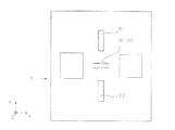
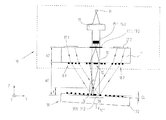
図1a及び1bは、本発明のエンコーダの第1の実施の形態の基準パルス信号を生成する部分走査光路を異なる視点で非常に概略的に示す。図1cは、このエンコーダ内でインクリメンタル信号を生成する概略的な部分走査光路を示す。 FIGS. 1 a and 1 b very schematically show the partial scanning optical path for generating the reference pulse signal of the first embodiment of the encoder of the invention from different viewpoints. FIG. 1c shows a schematic partial scan path that generates an incremental signal within this encoder.
図1a〜1c及び別の実施形に対する以下の類似の図では、基準パルス信号を生成する部分走査光路がそれぞれ実線で示されていて、これに対してインクリメンタル信号を生成する部分走査光路はそれぞれ破線で示されている。 In the following similar figures for FIGS. 1a to 1c and another embodiment, the partial scanning optical paths that generate the reference pulse signal are each shown by a solid line, whereas the partial scanning optical paths that generate the incremental signal are each a broken line. It is shown in
本発明の光学式エンコーダの示された形態は、反射基準尺30及びこの反射基準尺30の少なくとも1つの測定方向xに沿って移動する走査ユニット10を有する。反射基準尺30及び走査ユニット10は、相対移動する2つの物体、例えば機械の部品に接合されている。相対移動するこれらの両物体の位置に関する位置信号が、エンコーダによって生成されて−図示されなかった−制御ユニットに供給される。制御目的のため、この制御ユニットは、公知の方法でこれらの位置データを利用する。この場合、本発明のエンコーダは、直線状のシフト移動及び回転式のシフト移動の双方に関して構成され得る。
The illustrated form of the optical encoder of the present invention comprises a
本発明のエンコーダのこの示された実施の形態は、−以下で説明するように−周期的なインクリメンタル信号INCA,INCBのほかに測定区間に沿った少なくとも1つの既知の基準位置xREfに対する基準パルス信号RIをさらに供給する。次いで明らかに高い分解能のインクリメンタル測定が、こうして特定された既知の絶対位置に一般的な方法で引き続き適用され得る。 This illustrated embodiment of the encoder of the present invention, as will be described below, for a cyclic incremental signal INC A , INC B , as well as for at least one known reference position x REf along the measurement interval A reference pulse signal RI is further supplied. Clearly higher resolution incremental measurements can then be applied in a general manner to the known absolute positions thus identified.
最初に、本発明に対して優先する基準パルス信号RIの生成をこのために設けられている部分走査光路に基づいて説明する。 First, the generation of the reference pulse signal RI having priority over the present invention will be described based on the partial scanning optical path provided for this purpose.
反射基準尺30は、測定方向xに延在する1つ又は多数のインクリメンタル目盛33.1,33.2のほかに1つの特定の基準位置xREFに対する少なくとも1つの基準マーク31をさらに有する。当然に目盛(Grds.)を付けてもよく、例えばいわゆるディスタンスコードの基準マーク等の形態で多数の基準マークを異なる基準位置に配置してもよい。
The
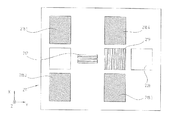
図2中の反射基準尺30の一部の正面図から分かるように、インクリメンタル信号INCA,INCBを生成するこの実施の形態では、平行で同一な2つのインクリメンタル目盛33.1,33.2が、支持本体32上に配置されている。これらの両インクリメンタル目盛33.1,33.2はそれぞれ、目盛周期TPINCで測定方向xに沿って周期的に配置された、異なる光学特性の線状の目盛領域から構成される。例えば反射基準尺30は、異なる移相作用を反射する部分光束に与える交互する部分領域である照射式の位相格子である。可能な実施形では、TPINC=0.5μmに選択される。目盛領域は、反射基準尺30の平面内で測定方向xに対して垂直に、すなわち示されている方向y(以下で線分方向とも言う)に沿って延在する。
As can be seen from the front view of a part of the
基準マーク31が、インクリメンタル目盛33.1,33.2用の両トラック間の基準位置xREFに対して配置されている。基準マーク31は、インクリメンタル目盛33.1,33.2のように異なる反射特性を有する部分領域つまり構造要素31.1,31.2の一定の配置から構成される。以下に、基準マーク31の好適な構成を提案されている実施の形態に対してさらに詳しく説明する。
A
この例では、光源14、例えばレーザーダイオード,コリメート光学系16,基準パルス信号を生成する多数の検出要素15.1,15.2,インクリメンタル信号を生成する多数の検出要素20.1,20.2,20.3(図1c)及びその他の異なる光学要素が、走査ユニット10の側面上に配置されている。この場合、基準パルス信号RI及びインクリメンタル信号INCA,INCBを生成するいろいろな光学要素が、走査ユニット10内の走査板10上に配置されていて、引き続き同様にさらに詳しく説明する。
In this example, the
この点に関して、光源14,コリメート光学系16及びいろいろな検出要素15.1,15.2,20.1,20.2,20.3は、走査ユニット10又は走査ユニット10に対応するハウジング内で必須のものではない。すなわち本発明の別の実施の形態では、これらの要素を公知の方法で光ファイバを用いて走査ユニット10に敷設し、いろいろな要素を空間的に分離して走査ユニット10の外側に配置することも基本的に可能である。
In this regard, the
コリメート光学系16後の平行に指向された部分光束が、分割格子19から基準パルス信号RIを生成する(図1a〜1c中の実線の)走査光路とインクリメンタル信号INCA,INCBを生成する(図1a〜1c中の破線の)走査光路とに分割される。図1bから分かるように、このことは、基準パルス信号を生成するために分割された部分光束が両インクリメンタル目盛33.1,33.2間の領域内の反射基準尺30上で回折されることを意味する。走査ユニット10と反射基準尺30との間の標準走査距離の場合に、両インクリメンタル目盛33.1,33.2間の中央の領域が正確に照射されるように、分割格子19の格子定数が主に選択される。走査ユニット10の方向の後方反射が、この領域から生じる。後方反射した部分光束が、走査ユニット10内の走査板11の下面に配置されている結像光学系12上に当たる。結像光学系12は、いろいろな形態で、例えば個別のフレネルレンズとして走査板11上に構成され得る。この代わりに結像光学系12を多数の単レンズから成るレンズアレイとして構成することも可能である;これについて以下の説明の中でさらに詳しく説明する。
The partial light beams directed in parallel after the collimating
両インクリメンタル目盛33.1,33.2間の基準マーク31の配置は、反射基準尺30及び走査ユニット10の場合によっては起こりうるz軸線周りの回転時に、インクリメンタル信号INCA,INCBに対する基準パルス信号RIの位置が(不正確に)変化しないという利点を奏する。
The arrangement of the reference marks 31 between the two incremental scales 33.1, 33.2 is such that the reference pulses for the incremental signals INC A , INC B during rotation around the z-axis which may occur in some cases of the
結像光学系12の結像側の焦点面が、走査板11の表面つまりそこに存在する絞り面に重なるように、この結像光学系12は光学的に寸法決めされている。それぞれ多数のアパーチャを有する2つの絞り構造13.1,13.2が、絞り面内に配置されている。走査ユニット10内の2つの検出要素15.1,15.2が、絞り構造13.1,13.2の後方に配置されている。これらの検出要素15.1,15.2は、アパーチャを透過する光を検出するために、すなわち基準パルス信号RIを生成するために利用される信号S1,S2を検出するために働く。物体側では、結像光学系12によって結像された焦点が、中立回転点と反射基準尺30の表面との間の半分の距離の高さに存在する。すなわち結像光学系12が、物体側で系に依存した中立回転点の位置から生じる平面つまり一点に調整されている。この場合、位置測定時の誤差が生じることなしに、すなわち基準パルス信号RI又はインクリメンタル信号INCA,INCBの生成時の誤差が生じることなしに、走査ユニット10又は反射基準尺30が、一点の周りで傾斜してもよいこの一点が、中立回転点として規定されている。この場合、この中立回転点は、系の条件に応じて異なる平面、すなわち基準尺面や基準尺面の下面又は上面に位置させてもよい。
The imaging
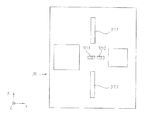
基準パルス信号RIを本発明にしたがって生成するための基準は、反射基準尺30の側面上の基準マーク31の選択された構成である。この基準マーク31の適切な構成が、基準パルス信号RIを基準位置xREFで確実に検出可能にする。基準マーク31をより詳しく説明するため、特に図2を参照のこと。図2は、反射位置xREFの領域内の反射基準尺30の正面図である。
The reference for generating the reference pulse signal RI according to the present invention is a selected configuration of the
本発明にしたがって構成された基準マーク31は、両インクリメンタル目盛33.1,33.2間の基準位置xREFの領域内に一組の第1構造要素31.1及び一組の第2構造要素31.2を所定の幾何配置で有する。両組のこれらの構造要素31.1,31.2は、測定方向xに対して垂直に、すなわち配置された線分方向yに沿って第1の横周期性T1又は第2の横周期性T2で周期的に配置されている。この場合、第1の構造要素31.1及び第2の構造要素31.2の両組の横周期性T1,T2は、図2から分かるように互いに異なっている;例えばT1=2.4μm及びT2=2.0μmに選択され得る。
A
図2に示された実施の形態では、基準マーク31は、測定方向xに沿って平行に互いに隣接して配置されている全部で4組の独立した第1構造要素31.1及び全部で4組の独立した構造要素32.1を有する。それ故に全部で8組の構造要素31.1,31.2が、測定方向xに沿って配置されている。それぞれ4組の第1構造要素31.1及び第2構造要素32.2は、測定方向xに沿って対称軸線Sに対してミラー対称に配置されている。この対称軸線Sは、反射基準尺30の平面内で測定方向xに対して垂直に指向されている。対称軸線Sは、この例では基準位置xREFに対して正確に存在する。異なる横周期性T1,T2の構造要素31.1,31.2が、対称軸線Sに対してミラー対称に対向している。
In the embodiment shown in FIG. 2, the reference marks 31 are arranged in a total of four independent first structural elements 31.1 and a total of four arranged adjacent to each other in parallel along the measuring direction x. It has a set of independent structural elements 32.1. Therefore, a total of eight structural elements 31.1 and 31.2 are arranged along the measuring direction x. The four sets of the first structural element 31.1 and the second structural element 32.2 are arranged in mirror symmetry with respect to the symmetry axis S along the measuring direction x. The symmetry axis S is oriented perpendicular to the measurement direction x in the plane of the
図2中の基準マーク31の拡大部分から分かるように、個々の構造要素31.1,31.2はそれぞれ、この例では横方向yに平行に延在する2本の境界直線及び長手方向xに湾曲し平行な2本の境界直線から構成されている断面形状を有する。これらの要素の後でさらに詳しく説明する光学作用が、この選択された横断面形状から生じる。第1構造要素31.1及び第2構造要素31.2を有する複数の組が、異なる横周期性T1,T2によって区別が付く。これらの個々の構造要素31.1,31.2は、この異なる横周期性T1,T2で周期的に配置されている。
As can be seen from the enlarged portion of the
基準パルス信号RIを生成するために利用される部分光束が、走査ユニット10の分割格子19から来て複数組の第1構造要素31.1及び第2構造要素31.2を有する基準マーク31の領域上に当たる場合、これらの部分光束は、異なる組の異なる横周期性T1及びT2に起因してy−z平面内のy方向にも異なって回折される。この場合、それぞれの回折角度は、公知のようにそれぞれの横周期性T1,T2に直接関連している。基準マーク31の領域から後方反射した部分光束が、走査ユニット10内の結像光学系12を透過して絞り面内に結像される。そこに配置された2つの絞り構造13.1,13.2が、それぞれの多数のアパーチャの幾何配置に関連して複数組の基準マーク31の第1構造要素31.1及び第2構造要素31.2の幾何配置に合わせられている。すなわち、第1絞り要素13.1の開口部は、複数組の第1構造要素31.1の配置に合わせられていて、第2絞り構造13.2の開口部は、第2構造要素31.2の複数の組の配置に合わせられている。このことは、図2と3bとの比較から分かる。すなわち図2中に示された例による基準マークでは、4組の第1構造マーク31.1が設けられている。示された4つのアパーチャを有し、これらの4組の第1構造マーク31.1に合わせられた第1絞り構造13.1が、これらの4組の第1構造マーク31.1に割り当てられている;同様に、4組の第2絞り構造要素31.2に合わせられた第2絞り構造13.2のアパーチャが、4組の第2絞り構造要素31.2に割り当てられている;明らかにその他の数の組のアパーチャ及び構造要素も選択され得る。アパーチャの位置を選択する場合、結像光学系12に起因して生じる結像スケールmを当然にさらに考慮する必要がある。
The partial light beam used to generate the reference pulse signal RI comes from the split grating 19 of the
このような調整の結果、絞り構造13.1,13.2に後続配置された両検出要素15.1,15.2がそれぞれ、基準位置xREFに隣接した領域内でこれらの検出要素15.1,15.2によって検出される信号S1,S2の信号最大値を検出できる。 The result of such adjustment, the diaphragm structure 13.1, 13.2 arranged downstream are both detection elements 15.1, 15.2 are respectively, a reference position x REF these detection elements adjacent to the region 15. 1, 15.2 can detect the signal maximum value of the signals S1, S2.
既に上述したように、結像光学系は、代わりに多数の単レンズを有するレンズアレイとしても構成され得る。これによって、線分方向yにより長い構造要素を有する組が、絞り面内に結像され得る。このことには、検出された信号の信号強度に関する利点がある。この場合、構造要素を有する1組の各部分配列が、1つの単レンズによって結像される。この別形態でも、絞り構造13.1,13.2の1つのアパーチャが、構造要素31.1,31.2の各組に限定して割り当てられている。同様に、アパーチャの位置が、結像スケールmを有する結像光学系12を介した構造要素31.1,31.2の組の結像から調整されて得られる。
As already mentioned above, the imaging optics can also be configured as a lens array having a number of single lenses instead. As a result, a set having a longer structural element in the line segment direction y can be imaged in the aperture plane. This has the advantage regarding the signal strength of the detected signal. In this case, each set of partial arrays having structural elements is imaged by one single lens. Also in this alternative form, one aperture of the diaphragm structures 13.1, 13.2 is assigned limited to each set of the structural elements 31.1, 31.2. Similarly, the position of the aperture is obtained by adjusting from the imaging of the set of the structural elements 31.1 and 31.2 via the imaging
基準位置xREFの周りの領域内の検出要素15.1,15.2で発生する信号S1,S2が、図4a中に示されている。興味対象の基準パルス信号RIが、どのようにしてこれらの信号S1,S2から最終的に生成可能であるかを以下の説明の過程でさらに詳しく説明する。 Signals S1, S2 generated by the detection elements 15.1, 15.2 in the region around the reference position x REF is shown in Figure 4a. How the reference pulse signal RI of interest can finally be generated from these signals S1, S2 will be described in more detail in the course of the following description.
インクリメンタル信号INCA,INCBを生成するための説明は、特に図2及び図1a及び1bを参照のこと。これらの図では、インクリメンタル信号を生成する部分走査光路がそれぞれ破線で示されている。 See especially FIG. 2 and FIGS. 1a and 1b for an explanation for generating the incremental signals INC A and INC B. In these drawings, the partial scanning optical paths for generating the incremental signals are indicated by broken lines.
この場合、光源14から放出されたインクリメンタル信号を生成する光束が、分割格子19を回折されずに透過した後に反射基準尺32上のインクリメンタル目盛33.2に到達する。x−z平面内で分割された部分光束が、インクリメンタル目盛33.2から走査ユニット10の方向に後方反射し、走査板11に配置された走査格子18.3,18.4の下面を透過する(図1a)。これらの走査格子18.3,18.4は、部分光束をy方向に回折させる。その結果これらの部分光速は、走査板11の上面の2つの反射要素17.1,17.2上に当たる(図1b)。これらの両部分光束は、これらの反射要素17.1,17.2から走査板11の下面上の別の走査格子18.1,18.2の方向に後方反射する。次いでこれらの走査格子18.1,18.2は、部分光速を反射基準尺30上の第2インクリメンタル目盛33.1の方向に再び後方回折させる(図2)。これらの部分光速は、インクリメンタル目盛33.1から走査板10の方向にもう1回後方反射する。後方反射したこれらの両部分光速は、走査ユニット10で走査板11の下面上の結合格子18.5上に到達する。3対の干渉する部分光束が、結合格子18.5から後続配置された3つの検出要素20.1,20.2,20.3の方向に最後に伝播する。これらの検出要素20.1,20.2,20.3は、120°ずつだけ移相している周期信号を検出するために使用される。これらの周期信号は、移相に応じて変調される。これらの変調された周期信号は、さらに公知の方法で−示されなかった−後続配置された電子機器によって90°だけ移相している2つのインクリメンタル信号INCA,INCBに最後に変換される。インクリメンタル走査に関してその他の点は、本出願人のドイツ連邦共和国特許出願第102006042743.2号明細書を参照のこと。
In this case, the luminous flux that generates the incremental signal emitted from the
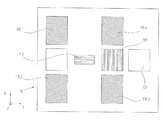
基準パルス信号RI及びインクリメンタル信号INCA,INCBの双方を生成するための異なる光学要素の配置が、図3a及び3b中に示されている。 Different optical element arrangements for generating both the reference pulse signal RI and the incremental signals INC A , INC B are shown in FIGS. 3a and 3b.
既に上述したように、信号S1,S2が、図4a中に示されているように基準位置xREFの領域内で検出要素15.1,15.2によって生成される。しかしながら、特に先に説明されているような、例えば0.5μmの信号周期を有する高い分解能のインクリメンタル信号INCA,INCBが利用される場合、約15μmを有する信号S1,S2の幅は、基準パルス信号RIに対してはまだ十分に狭くない。この場合、基準位置xREFの領域内で、生成されたインクリメンタル信号INCA,INCBの幅に一致する幅を有する基準パルス信号RIを出力側で自由に処理できることが基本的に望ましい。この実施の形態では、この理由から、信号S1,S2が、図5中に示された回路配置によって以下で説明するようにさらに処理される。
As already mentioned above, the signal S1, S2 is generated by the detection elements 15.1, 15.2 in the region of the reference position x REF, as shown in Figure 4a. However, when high-resolution incremental signals INC A and INC B having a signal period of 0.5 μm, for example, as described above are used, the widths of the
この場合、検出要素15.1,15.2の信号S1,S2が、電流電圧変換器21.1,21.2に最初に供給される。引き続き和信号S1+S2及び差信号S1−S2が、後続接続された加算器22及び減算器23によって生成される;これらの付随する和信号及び差信号S1+S2,S1−S2が、図4b中の基準位置xREFの範囲内に示されている。引き続き和信号S1+S2が、第1比較器24.1に供給される。基準信号又はトリガー閾値TR1が、第1比較器24.1の他方の入力部に入力される。差信号S1−S2が、第2比較器24.2及び第3比較器24.3に入力される。トリガー閾値TR3及びTR2が、基準信号としてこれらの第2比較器24.2及び第3比較器24.3の他方の入力部に入力される。図4b中には、和信号S1+S2及び差信号S1−S2に対する異なるトリガー信号TR1,TR2及びTR3の位置が示されている。引き続き第1比較器24.1の出力信号が、ANDゲート25.1の第1入力部に供給される。第2ANDゲート25.2の出力信号が、ANDゲート25.1の第2入力部に供給される。第2比較器24.2,及び第3比較器24.3の出力信号が、第2ANDゲート25.2に供給される。トリガー閾値TR1,TR2,TR3の示されている選択及び生じる論理AND結合の場合、希望する基準パルス信号RIが、ANDゲート25.1の出力部に出力される。図4c中に示されているように、希望する基準パルス信号RIは、幅bRI=0.5μmを有し、この幅bRI=0.5μmは、生成されたインクリメンタル信号INCA,INCBの幅bINCに一致する。
In this case, the signals S1, S2 of the detection elements 15.1, 15.2 are first supplied to the current-voltage converters 21.1, 21.2. Subsequently, the sum signal S1 + S2 and the difference signal S1-S2 are generated by the subsequently connected
以下に、反射基準尺30の側面上の基準マーク31の好適な構成をさらに詳しく説明する。以下で説明する手段によって、基準パルス信号RIの生成時の中立回転点の位置が、インクリメンタル信号の生成時の中立回転点の位置に適合され得ることを特に保証することができる。既に上述したように、このことは、走査ユニット10及び反射基準尺30の場合によっては起こりうる傾き時の誤測定を回避するための重要な手段である。
Hereinafter, a preferred configuration of the
この目的のため、既に上述した基準マーク31の構造要素31.1,31.2を回折光学素子又は回折構造要素として構成することが提唱されている。これらの回折光学素子又は回折構造要素は、測定方向xに所定の焦点距離fを有するシリンダレンズのように光学的に作用し、したがって測定方向xに虚焦点又は実焦点を反射基準尺から焦点距離fの距離で有する。y−z平面内では、構造要素31.1,31.2が、横周期性T1又はT2を有する格子として機能するように、これらの構造要素31.1,31.2は、光学作用を有する。
For this purpose, it has been proposed to construct the structural elements 31.1, 31.2 of the
インクリメンタル信号走査の中立回転点が、系に起因して反射基準尺30の上方又は下方にある場合、構造要素31.1,31.2の選択された焦点距離fが、インクリメンタル信号走査の中立回転点の半分の距離に一致する。この方法により、基準パルス信号生成の中立回転点の位置が、インクリメンタル生成の中立回転点の位置に適合され得る。したがって、さもなければ走査ユニット10及び反射基準尺30の場合によっては起こりうる傾き時に生じる位置測定時の誤差を回避することができる。
If the neutral rotation point of the incremental signal scan is above or below the
さらに、走査ユニット10内の結像光学系12を物体側で構造要素31.1,31.2の焦点面の位置に適合することが提唱されている。この焦点面は、結合光学系12を介して絞り構造13.1,13.2が配置されている絞り面内に結像される。これらの要件は、結像光学系12の位相関数によって以下のように表わすことができる:
Furthermore, it has been proposed that the imaging

λD = 使用される光源の波長
x = 測定方向の座標
a1 = 基準尺平面と結像光学系との間の距離
a2 = 結像光学系と絞り面との間の距離
n = 走査板の屈折率
f = 基準マークの構造要素の焦点距離
この場合、位相関数は、結像光学系12の等高線状のこの結合光学系12の幾何学的形状を示す。
λ D = wavelength of light source used x = coordinate in measurement direction a 1 = distance between reference scale plane and imaging optical system a 2 = distance between imaging optical system and diaphragm surface n = scanning plate In this case, the phase function indicates the geometric shape of the coupling
結合光学系12の結像スケールmが、特に以下のように選択される:
The imaging scale m of the coupling
a1 = 基準尺平面と結像光学系との間の距離
a2 = 結像光学系と絞り面との間の距離
n = 走査板の屈折率
f = 基準マークの構造要素の焦点距離
図6a中には、中立回転点Nが走査条件で明らかに基準尺平面の下に存在する事実が概略的に示されている。基準マーク31の構造要素31.1,31.2の焦点距離fが、明らかなように反射基準尺30から中立回転点Nの距離の半分に等しく選択され、結像光学系12が、この焦点距離の位置に調整される。
a 1 = distance between the reference scale plane and the imaging optical system a 2 = distance between the imaging optical system and the stop surface n = refractive index of the scanning plate f = focal length of the structural element of the reference mark In the figure, the fact that the neutral rotation point N is clearly below the reference scale plane in the scanning conditions is schematically shown. The focal length f of the structural elements 31.1, 31.2 of the
これに対して図6bは、中立回転点Nが走査条件により明らかに基準尺平面の上に存在する場合を概略的に示す。基準マーク31の構造要素31.1,31.2の焦点距離fは、明らかなように反射基準尺30から中立回転点Nの距離の半分に同様に等しく選択され、結像光学系12が、この焦点距離の位置に同様に調整される。
In contrast, FIG. 6b schematically shows the case where the neutral rotation point N is clearly on the reference scale plane due to the scanning conditions. The focal length f of the structural elements 31.1, 31.2 of the
図6bによる状況の場合、y方向に沿った軸線周りの反射基準尺30の場合によっては起こりうる角度値αだけの傾き時に(図6c)、結像光学系12の焦点の変位は、直線近似で2fαだけである。これは、インクリメンタル信号の変位量に一致する。すなわち基準信号の生成及びインクリメンタル信号の生成は、傾きによって同等に影響を受ける。
In the case of the situation according to FIG. 6b, the displacement of the focal point of the imaging
したがって本発明の基準マークの構成によって、基準パルス信号の生成の中立回転点が、インクリメンタル信号の生成の中立回転点に一致する。このとき両信号は、本発明の手段に起因して走査ユニットに対する反射基準尺の場合によっては起こりうる傾きによって影響を受ける。所定の光学作用の構造要素を有する上述した解決手段は、インクリメンタル信号の生成の中立回転点が走査原理によって基準尺平面から明らかに離れている場合に対して特に有益に、基準パルス信号の生成の中立回転点の位置の適合を可能にする。 Therefore, according to the configuration of the reference mark of the present invention, the neutral rotation point for generating the reference pulse signal coincides with the neutral rotation point for generating the incremental signal. At this time, both signals are affected by the tilt that may occur in some cases of the reflection reference scale for the scanning unit due to the means of the present invention. The solution described above having a predetermined optical working structure is particularly useful for the case where the neutral rotation point of the incremental signal generation is clearly separated from the reference plane by the scanning principle. Allows the position of the neutral rotation point to be adapted.
対応する走査原理の場合、インクリメンタル信号の生成の中立回転点が、基準尺平面に対して比較的近くに隣接して存在することもさらに可能である。この場合、個々の組の構造要素を説明したシリンダレンズの光学特性で構成するのではなくて、構造要素の横断面を四角形に構成することが有益であると実証されている。一方では所定の光学作用を呈する上述した構造要素を有する組と他方ではこのような光学作用なしの構造要素を有する組との混合配置が、基準パルス信号の生成の中立回転点を基準尺平面の直近に移動することを可能にする。 In the case of a corresponding scanning principle, it is further possible that the neutral rotation point of the generation of the incremental signal is present relatively close to the reference scale plane. In this case, it has proved to be advantageous to construct the cross-section of the structural elements in a square rather than configuring the individual sets of structural elements with the optical characteristics of the cylinder lens described. On the one hand, the mixed arrangement of the set having the above-described structural element exhibiting a predetermined optical action and the set having the structural element without such an optical action on the other side makes the neutral rotation point of the generation of the reference pulse signal the reference scale plane. Allows you to move most recently.
以下に、上述した第1の実施形と僅かに異なる本発明のエンコーダの第2の実施形を図7a,7b及び8a,8bに基づいて説明する。図7a及び7bは、先の例と同様に第2の実施形の部分走査光路を同様に示す。図8a及び8b中には、走査板の下面及び上面の正面が示されている。以下では主に、第1の実施の形態と異なる要素又は機能だけを説明する。 In the following, a second embodiment of the encoder according to the invention, which is slightly different from the first embodiment described above, will be described on the basis of FIGS. 7a, 7b and 8a, 8b. Figures 7a and 7b similarly show the partial scanning optical path of the second embodiment as in the previous example. 8a and 8b show the front face of the lower and upper faces of the scanning plate. In the following, only elements or functions different from those of the first embodiment will be mainly described.
図中では、実線の部分走査光路は、基準パルス信号を生成するために使用する部分走査光路を示し、破線で示された部分走査光路は、インクリメンタル信号を生成する部分走査光路を示す。 In the drawing, a solid partial scanning optical path indicates a partial scanning optical path used for generating a reference pulse signal, and a partial scanning optical path indicated by a broken line indicates a partial scanning optical path for generating an incremental signal.
最初の例とは異なり、一方では反射基準尺330上の基準マーク331が収束照射される。基準マーク331の収束照射は、基準パルス信号の生成の中立回転点の位置が反射基準尺330と走査ユニット310との間の距離にほとんど依存しないという利点を呈することが実証されている。図7b中には、走査格子319と基準マーク331との間の収束照射光路が示されている。この距離からインクリメンタル信号の生成の中立回転点の位置のこの非依存性は、インクリメンタル目盛333.1,333.2の選択された走査によってさらに保証されている。
Unlike the first example, on the other hand, the
基準マーク331のこのような収束照射を保証するため、示された実施の形態では、図8a中の走査板311の下面の正面でも示さされている走査ユニット310内の分割格子319が、湾曲した格子線を有する回折分光器の形態の結像レンズとして構成される。
In order to ensure such convergent irradiation of the
第2の実施の形態では、結像レンズとしての分割格子319の構成が、走査光路を新たに変更させる。したがって、生じる基準パルス信号が、走査距離の変化時でも位置に応じて変化しないように、分割格子319と走査板311上の絞り構造313.1,313.2とが互いに精確に整合されていることが重要である。これらの要素の精確な整合を製造時に技術的に簡単に実現できるようにするため、絞り構造313.1,313.2及び分割格子319が、第1の実施の形態と異なって走査板311の同じ側面上に配置されることがこの第2の実施の形態で提唱されている。図8aは、走査板311の下面を示す。この場合、それぞれの絞り構造313.1,313.2が、結像光学系312.1,312.2の要素に隣接してy方向に配置されている。
In the second embodiment, the configuration of the split grating 319 as the imaging lens newly changes the scanning optical path. Therefore, the split grating 319 and the aperture structures 313.1 and 313.2 on the
この代わりに、絞り構造及び分割格子を走査板の上面に取り付けることも通常可能である。 Instead of this, it is usually possible to attach the diaphragm structure and the dividing grating to the upper surface of the scanning plate.
この例の絞り構造313.1,313.2を走査板311の下面に配置できるようにするため、例えば図8b中に示されているように、走査光路内に先の例とは異なって反射素子321.1,321.2が、走査板311の上面にさらに配置されている。この走査光路を考慮した場合、−図7b中で分かるように−基準マーク331から走査ユニット310の方向に反射した部分光束が、最初に−この例では二つの部分から成る−結像光学系312.1,312.2から追加の反射素子321.1,321.2を介して走査板311の下面の絞り構造313.1,313.2の平面内に結像される。反射素子321.1,321.2が、図8b中の走査板311の上面の正面内で確認できる。このとき、検出素子315.1,315.2の方向の後方反射が、走査板311の下面の絞り構造313.1,313.2によって生じる。この光路に起因して、この実施の形態の絞り構造313.1,313.2は、当然に光透過に/光非透過に構成された構造として構成されていなくて、反射する/反射しない構造として構成されている。
In order to allow the diaphragm structures 313.1 and 313.2 of this example to be arranged on the lower surface of the
第1の実施の形態に比べて僅かに変更した基準パルス信号を生成するためのこの走査光路は、さらなる別の変更を最終的に引き起こす。したがって図7bから分かるように、結像する光学作用のほかに、y方向のそれぞれの横方向の回折作用も、結像光学系312.1又は312.2によって生じることが必要である。図8a中の走査板311の下面の正面で概略的に示されているように、このことは、結像光学系312.1,312.2がそれぞれ回折格子レンズ構造として構成される場合に保証され得る。
This scanning optical path for generating a reference pulse signal that is slightly modified compared to the first embodiment ultimately causes another further modification. Therefore, as can be seen from FIG. 7b, in addition to the optical action of imaging, the lateral diffractive action in the y direction must also be caused by the imaging optics 312.1 or 312.2. This is assured if the imaging optics 312.1, 312.2 are each configured as a diffraction grating lens structure, as schematically shown in front of the lower surface of the
この実施の形態では、基準パルス信号及びインクリメンタル信号の生成は、説明した変更以外は先に説明した例のように機能する。 In this embodiment, the generation of the reference pulse signal and the incremental signal functions as in the example described above except for the changes described above.
最後に本発明のエンコーダの2つの別の実施の形態を説明する。これらの実施の形態の場合、説明した両実施の形態に比べて、追加の手段が、特定の誤差の影響を補償するために設けられる。すなわち、光源から走査板に対して基準マーク方向に来る光束が伝播する角度の望まない変化時に、誤差が基準パルス信号の生成時に生じることが分かっている。 Finally, two alternative embodiments of the encoder of the present invention will be described. In these embodiments, additional means are provided to compensate for the effects of certain errors compared to both described embodiments. That is, it has been found that an error occurs when generating the reference pulse signal when the angle at which the light beam coming from the light source toward the reference mark propagates in the direction of the reference mark is undesirably changed.
本発明の第3の実施の形態を図9a〜9cに基づいて説明する。この第3の実施の形態は、走査ユニット側に基準パルス信号及びインクリメンタル信号を生成する上述した成分のほかに補正手段をさらに有する。これらの補正手段は、補助信号の生成を可能にする。これらの補助信号は、先に説明した−誤差を引き起こす−角度変化に対する目安を示し、このような誤差の排除を考慮して評価され得る。以下の説明では、補助信号の生成及び利用だけを説明する。基準パルス信号及びインクリメンタル信号の生成は、使用される走査原理に関して第1の実施の形態に等しい。 A third embodiment of the present invention will be described with reference to FIGS. The third embodiment further includes correction means on the scanning unit side in addition to the above-described components that generate the reference pulse signal and the incremental signal. These correction means make it possible to generate auxiliary signals. These auxiliary signals provide an indication for the angular changes described above-causing errors-and can be evaluated taking into account the elimination of such errors. In the following description, only the generation and use of auxiliary signals will be described. The generation of the reference pulse signal and the incremental signal is equivalent to the first embodiment with respect to the scanning principle used.
補正手段は、図9a中には走査ユニット110の走査板111の右の部分の領域内に配置されていて、そこに符号126,127,128.1,129.1,129.2で付記されている。図9b及び9cは、第1の実施の形態と同様に補正手段127,128.1,128.2又は126を有する走査板111の上面及び下面の正面を示す。
In FIG. 9a, the correcting means is arranged in the area of the right portion of the
補助信号を生成するため、図9aにしたがって、1本の部分光束が、分割格子119を介して光源114から来る光束から分離される。分離された部分光束は、反射するフレネルレンズ127の方向に伝播する。このフレネルレンズ127は、走査板111の上面に配置されている。フレネルレンズ127の結像側の焦点が、分割格子119の平面内に存在するように、このフレネルレンズ127は光学的に寸法決めされている。部分光束が、補助信号を生成するフレネルレンズ127から走査板111の下面の反射素子126の方向に偏向される。この反射素子126は、フレネルレンズ127の焦点面内に配置されている。部分光束が、反射素子126から走査板の上面の方向に後方偏向する。この場合、互いに垂直に配置された異なる格子定数の2つの周期格子構造128.1,128.2が設置されている。2つの補助信号検出素子129.1,129.2が、これらの周期格子構造128.1,128.2の後方に配置されている。これらの補助信号検出素子129.1,129.2は、これらの格子構造128.1,128.2によって回折された部分光束を検出する。
In order to generate the auxiliary signal, one partial light beam is separated from the light beam coming from the
図10から分かるように、両補助信号の検出要素129.1,129.2が、減算器142によって互いに減算される。発生した差信号が、補助信号として調整可能な増幅器143に供給される。トリガー閾値TR2が、この増幅器142の出力部に出力されるか、又は、トリガー閾値TR3が、調整要素144を通じて出力される。調整要素144は、例えば制御可能なツェナーダイオードとして構成され得る。一定な電圧降下が、このツェナーダイオードによって設定される。したがって基準パルス信号の幅は同じままで、この基準パルス信号の位置だけが後に制御される。
As can be seen from FIG. 10, the detection elements 129.1 and 129.2 of both auxiliary signals are subtracted from each other by the
こうして生成されたトリガー閾値TR2,TR3は、図5の回路配置内で比較器24.2,24.3の基準信号又はトリガー閾値として利用され得る。 The trigger threshold values TR2 and TR3 thus generated can be used as reference signals or trigger threshold values for the comparators 24.2 and 24.3 in the circuit arrangement of FIG.
この実施の形態では、光源114から来る光束の入射角が、測定方向xに場合によっては変化すると、格子構造128.1,128.2の移行領域内で生成した像の位置が変化する。その結果、生じた差信号が同様に変化する。したがってこの差信号は、このような角度変化に対する目安として機能され得る。
In this embodiment, when the incident angle of the light beam coming from the
引き続き、補助信号を生成する補正手段の第2の実施形を有する本発明の装置の第4の実施形を図11a〜11cに基づいて説明する。 Subsequently, a fourth embodiment of the device according to the invention having a second embodiment of the correction means for generating the auxiliary signal will be described with reference to FIGS.
異なる補正手段が、図11a中に同様に再び走査ユニット210の走査板211の右側の部分の領域内に配置されていて、そこで符号226,227.1,227.2,228.1,229.1,129.2で付記されている。第3の例のように、図11b及び11cは、第1の実施の形態と同様に補正手段227.1,227.2,28.1,228.2又は226を有する走査板211の上面及び下面の正面を示す。
Different correction means are again arranged in the region of the right part of the
補助信号を生成するため、図11aにしたがって、1本の部分光束が、先の例のように分割格子219によって光源214から来る光束から分離される。引き続きこの部分光束は、反射基準尺230に面しない走査板211の側面に配置された格子レンズ構造227.1,227.2上に当たる。この格子レンズ構造227.1,227.2は、その幾何学構造及び光学構造に関して反射基準尺上の基準マーク321に一致し、焦点を分割格子219の平面内に有する。部分光束は、格子レンズ構造227.1,227.2から反射要素226の方向に後方反射する。この反射要素226は、走査板211の下面の格子レンズ構造227.1,227.2の焦点内に配置されている。そこから反射した部分光束が、多数のアパーチャを有する2つの絞り構造228.1,228.2上にさらに当たる。これらの絞り構造228.1,228.2のアパーチャを透過した光が、後続配置された補助信号の2つの検出要素229.1,229.2によって検出される。次いで補助信号の検出要素229.1,229.2の出力部に出力される信号が、先の例のように差信号に変換される。この差信号は、トリガー閾値TR2,TR3を調整する補助信号として使用される。このため、図10に基づいて既に説明したのと同じ回路配置が使用され得る。
In order to generate the auxiliary signal, according to FIG. 11a, one partial light beam is separated from the light beam coming from the
基準マークに向かう光束の入射角の上述した場合によっては起こりうる変動が、提唱されている補正手段のこれらの実施形によっても検出でき補正できる。 Variations that may occur in the above-described cases of the incident angle of the light beam toward the reference mark can also be detected and corrected by these proposed embodiments of the correction means.
説明した実施の形態のほかに、その他の構成の可能性も、本発明の範囲内で明らかに存在する。 Besides the described embodiments, other configuration possibilities are clearly present within the scope of the invention.
すなわち、例えば図1b中で認識可能な分割格子19から基準マーク31への照射光束の斜めの入射の代わりに、基準マーク31の垂直に入射する照射を実現することも可能である。このような実施形は、走査ユニット及び反射基準尺の場合によっては起こりうる特定の方向への傾き時の基準パルス信号の位置に関する利点を呈する。 That is, for example, instead of the oblique incidence of the irradiated light beam from the split grating 19 that can be recognized in FIG. Such an implementation presents an advantage with respect to the position of the reference pulse signal when tilting in a particular direction that may occur in some cases with the scanning unit and the reflective reference scale.
既に上述したように、さらにリニア式の測定配置及び回転式の測定は位置の双方を本発明の考えに基づいて構成することもできる。 As already mentioned above, both the linear measurement arrangement and the rotary measurement can also be configured in accordance with the idea of the present invention.
10 走査ユニット
11 走査板
12 結像光学系
14 光源
16 コリメート光学系
17 反射要素
19 分割格子
30 反射基準尺
31 基準マーク
32 支持本体
DESCRIPTION OF
Claims (10)
前記基準パルス信号(RI)を生成する前記走査ユニット(10)が、複数の光学要素を有し、これらの光学要素は、少なくとも1つの結合光学系(12)及びそれぞれ複数のアパーチャを含み、絞り面内に配置された少なくとも2つの絞り構造(13.1,13.2)であり、1つの光源(14)及び少なくとも2つの検出要素(15.2)が、前記走査ユニット(10)にさらに敷設されていて、
前記反射基準尺(30)は、少なくとも1つの基準位置(xREF)に対して基準マーク(31)を有し、
この基準マーク(31)は、少なくとも1組の第1構造要素(31.1)を有し、これらの第1構造要素(31.1)は、前記反射基準尺(30)の平面内に前記測定方向(x)に対して垂直に第1横周期性(T1)で周期的に配置されていて、
また、前記基準マーク(31)は、少なくとも1組の第2構造要素(31.2)を有し、これらの第2構造要素(31.2)は、前記反射基準尺(30)の平面内に前記測定方向(x)に対して垂直に第2横周期性(T2)で周期的に配置されていて、前記第1横周期性(T1)と前記第2横周期性(T2)とは互いに異なり、
これらの構造要素(31.1,31.2)は、回折構造要素として構成されていて、これらの回折構造要素は、所定の焦点距離(f)を有するシリンダレンズのように前記測定方向(x)に光学的に作用しかつ前記第1横周期性(T1)及び前記第2横周期性(T2)を有する回折格子のように前記測定方向(x)に対して垂直に作用する、当該エンコーダ。 It has a scanning unit (10) and a reflective reference scale (30) that moves in at least one measuring direction (x) with respect to this scanning unit (10), one for at least one reference position (x REF ) In an encoder that generates a reference pulse signal (RI),
It said scanning unit for generating said reference pulse signal (RI) (10) has a plurality of optical elements, these optical elements, at least one coupling optical system (12) and each include a plurality of apertures, aperture at least two diaphragm structure disposed on a plane (13.1 and 13.2), one light source (14) and at least two detection elements (15.2) further to the scanning unit (10) Laid,
The reflection reference scale (30) has a reference mark (31) with respect to at least one reference position (x REF ),
The reference mark (31) has at least one pair of the first structural element (31.1), these first structural element (31.1), the said in the plane of reflection the scale (30) Periodically arranged with a first transverse periodicity (T1) perpendicular to the measuring direction (x),
Also, the reference mark (31) has at least one pair of second structural element (31.2), these second structural element (31.2) is in the plane of said reflective measuring standard (30) It said measuring direction (x) relative to be arranged periodically in the second horizontal periodicity (T2) vertically, wherein the first lateral periodicity (T1) and the second lateral periodicity and (T2) in Different from each other
These structural elements (31.1, 31.2) is be configured as a diffractive structure elements, these diffractive structural elements, the measuring direction (x as a cylinder lens having a predetermined focal length (f) ) acting perpendicular to the measuring direction (x) as a diffraction grating with optically acting vital first lateral periodicity (T1) and the second lateral periodicity (T2), the said encoder .
前記走査ユニット(10)は、走査手段(17.1,17.2,18.1,18.2,18.3,18.4,20.1,20.2,20.3)を有し、これらの走査手段(17.1,17.2,18.1,18.2,18.3,18.4,20.1,20.2,20.3)は、反射基準尺(30)と走査ユニット(10)との相対移動時に周期的なインクリメンタル信号(INCA,INCB)を生成するために使用される、請求項1〜6のいずれか1項に記載のエンコーダ。 The reflective reference scale (30) further comprises at least one periodic incremental scale (33.1, 33.2) extending in the measuring direction (x),
The scanning unit (10) has scanning means (17.1, 17.2, 18.1, 18.2, 18.3, 18.4, 20.1, 20.2, 20.3). These scanning means (17.1, 17.2, 18.1, 18.2, 18.3, 18.4, 20.1, 20.2, 20.3) are provided with a reflection reference scale (30). a periodic incremental signal upon relative movement between the scanning unit (10) (INC a, INC B) is used to generate an encoder according to any one of claims 1-6.
Applications Claiming Priority (4)
| Application Number | Priority Date | Filing Date | Title |
|---|---|---|---|
| DE102006054780 | 2006-11-20 | ||
| DE102006054780.2 | 2006-11-20 | ||
| DE102007035345A DE102007035345A1 (en) | 2006-11-20 | 2007-07-27 | Position measuring device |
| DE102007035345.8 | 2007-07-27 |
Publications (3)
| Publication Number | Publication Date |
|---|---|
| JP2008129021A JP2008129021A (en) | 2008-06-05 |
| JP2008129021A5 JP2008129021A5 (en) | 2010-12-09 |
| JP5147367B2 true JP5147367B2 (en) | 2013-02-20 |
Family
ID=39031069
Family Applications (1)
| Application Number | Title | Priority Date | Filing Date |
|---|---|---|---|
| JP2007299738A Active JP5147367B2 (en) | 2006-11-20 | 2007-11-19 | Encoder |
Country Status (4)
| Country | Link |
|---|---|
| US (1) | US7714273B2 (en) |
| EP (2) | EP1923672B1 (en) |
| JP (1) | JP5147367B2 (en) |
| DE (1) | DE102007035345A1 (en) |
Families Citing this family (17)
| Publication number | Priority date | Publication date | Assignee | Title |
|---|---|---|---|---|
| ES2353355T5 (en) * | 2008-09-10 | 2014-03-31 | Fagor, S.Coop. | Optoelectronic measuring device |
| DE102008059667A1 (en) | 2008-11-26 | 2010-05-27 | Dr. Johannes Heidenhain Gmbh | Position measuring device for measuring position of movable carriage of machine with respect to machine bed, has scale carrier supported at hinge that pivots carrier around tilting axis, which runs parallel to neutral axis of rotation |
| DE102010029211A1 (en) | 2010-05-21 | 2011-11-24 | Dr. Johannes Heidenhain Gmbh | Optical position measuring device |
| JP5594496B2 (en) * | 2010-09-02 | 2014-09-24 | 株式会社安川電機 | Encoder, servo motor, and motor unit |
| CN102175376B (en) * | 2011-01-27 | 2012-06-27 | 哈尔滨工业大学 | Multi-laser-beam heterodyne micro-impulse-measuring device and method |
| DE102011076055A1 (en) * | 2011-05-18 | 2012-11-22 | Dr. Johannes Heidenhain Gmbh | Optical position measuring device |
| DE102012204572A1 (en) | 2012-03-22 | 2013-09-26 | Dr. Johannes Heidenhain Gmbh | Position measuring device and arrangement with such a position measuring device |
| DE102012021935A1 (en) | 2012-11-09 | 2014-05-15 | Dr. Johannes Heidenhain Gmbh | Optical position measuring device |
| CN103961133B (en) * | 2013-01-31 | 2018-09-11 | Ge医疗系统环球技术有限公司 | Patient body shape detects automatically and patient's intelligent positioning |
| DE102015209716B4 (en) | 2014-05-29 | 2023-04-20 | Mitutoyo Corporation | Optical encoder with adjustable resolution |
| DE102014214839A1 (en) | 2014-07-29 | 2016-02-04 | Dr. Johannes Heidenhain Gmbh | interferometer |
| JP6517516B2 (en) * | 2015-01-21 | 2019-05-22 | 株式会社ミツトヨ | Encoder |
| JP6519399B2 (en) * | 2015-08-13 | 2019-05-29 | 富士ゼロックス株式会社 | Measuring device and program |
| DE102016200847A1 (en) * | 2016-01-21 | 2017-07-27 | Dr. Johannes Heidenhain Gesellschaft Mit Beschränkter Haftung | Optical position measuring device |
| DE102017219125A1 (en) * | 2017-10-25 | 2019-04-25 | Dr. Johannes Heidenhain Gmbh | Optical position measuring device |
| DE102019219151A1 (en) | 2019-12-09 | 2021-06-10 | Dr. Johannes Heidenhain Gesellschaft Mit Beschränkter Haftung | Optical position measuring device |
| CN113405460B (en) * | 2020-03-16 | 2023-04-14 | 晋城三赢精密电子有限公司 | Micro-displacement measuring device |
Family Cites Families (16)
| Publication number | Priority date | Publication date | Assignee | Title |
|---|---|---|---|---|
| DE3416864C2 (en) * | 1984-05-08 | 1986-04-10 | Dr. Johannes Heidenhain Gmbh, 8225 Traunreut | Photoelectric measuring device |
| JPS61182523A (en) * | 1985-02-08 | 1986-08-15 | Mitsutoyo Mfg Co Ltd | Photoelectric type displacement detector |
| DE8717718U1 (en) * | 1987-08-11 | 1989-09-28 | Dr. Johannes Heidenhain Gmbh, 8225 Traunreut, De | |
| US5073710A (en) * | 1989-09-21 | 1991-12-17 | Copal Company Limited | Optical displacement detector including a displacement member's surface having a diffractive pattern and a holographic lens pattern |
| DE3939504A1 (en) * | 1989-11-30 | 1991-06-06 | Heidenhain Gmbh Dr Johannes | LIGHT ELECTRICAL POSITION MEASURING DEVICE |
| DE59207010D1 (en) * | 1992-06-17 | 1996-10-02 | Heidenhain Gmbh Dr Johannes | Measuring device |
| JP3358286B2 (en) * | 1994-03-31 | 2002-12-16 | ソニー・プレシジョン・テクノロジー株式会社 | Fixed point detector |
| US6229140B1 (en) * | 1995-10-27 | 2001-05-08 | Canon Kabushiki Kaisha | Displacement information detection apparatus |
| JP3775892B2 (en) * | 1996-05-20 | 2006-05-17 | 松下電器産業株式会社 | Optical encoder |
| US5981941A (en) * | 1996-05-20 | 1999-11-09 | Matsushita Electric Industrial Co., Ltd. | Optical encorder for detection having a moving reference point |
| DE19921309A1 (en) * | 1999-05-07 | 2000-11-09 | Heidenhain Gmbh Dr Johannes | Scanning unit for an optical position measuring device |
| WO2003021194A2 (en) * | 2001-08-30 | 2003-03-13 | Microe Systems Corporation | Reference point talbot encoder |
| GB0205972D0 (en) * | 2002-03-14 | 2002-04-24 | Renishaw Plc | Encoder with reference marks |
| DE102005006247A1 (en) * | 2005-02-11 | 2006-08-17 | Dr. Johannes Heidenhain Gmbh | Position measuring device |
| US7858922B2 (en) * | 2006-11-20 | 2010-12-28 | Dr. Johannes Heidenhain Gmbh | Position-measuring device |
| JP5286584B2 (en) * | 2007-06-19 | 2013-09-11 | 株式会社ミツトヨ | Absolute position measuring encoder |
-
2007
- 2007-07-27 DE DE102007035345A patent/DE102007035345A1/en not_active Withdrawn
- 2007-10-10 EP EP07019809A patent/EP1923672B1/en active Active
- 2007-10-10 EP EP07019810.6A patent/EP1923673B1/en active Active
- 2007-11-19 JP JP2007299738A patent/JP5147367B2/en active Active
- 2007-11-19 US US11/942,435 patent/US7714273B2/en active Active
Also Published As
| Publication number | Publication date |
|---|---|
| US7714273B2 (en) | 2010-05-11 |
| US20080117440A1 (en) | 2008-05-22 |
| DE102007035345A1 (en) | 2008-05-21 |
| EP1923672A2 (en) | 2008-05-21 |
| EP1923672A3 (en) | 2011-11-23 |
| JP2008129021A (en) | 2008-06-05 |
| EP1923673A3 (en) | 2012-11-14 |
| EP1923672B1 (en) | 2012-12-12 |
| EP1923673A2 (en) | 2008-05-21 |
| EP1923673B1 (en) | 2015-03-25 |
Similar Documents
| Publication | Publication Date | Title |
|---|---|---|
| JP5147367B2 (en) | Encoder | |
| JP5147368B2 (en) | Encoder | |
| JP5100266B2 (en) | Encoder | |
| JP5079874B2 (en) | Position measuring device | |
| US9766098B2 (en) | Optical position measuring instrument | |
| US7348546B2 (en) | Position measuring system with a scanning unit having a reference pulse signal detection unit | |
| JPH11142114A (en) | Scanning unit for optical position measuring apparatus | |
| JP4266834B2 (en) | Optical encoder | |
| JP5128368B2 (en) | Scale and encoder for encoder | |
| JP6908446B2 (en) | Position measuring device | |
| US9068811B2 (en) | Device for determining distance interferometrically | |
| JP2818800B2 (en) | Device for generating position-dependent signals | |
| US7404259B2 (en) | Optical position measuring instrument | |
| JP4936980B2 (en) | Optical encoder | |
| JP6875923B2 (en) | Scale device and biaxial displacement detector | |
| JP2009019876A (en) | Optical absolute value encoder | |
| US10190893B2 (en) | Encoder | |
| JP6293700B2 (en) | Encoder | |
| JP6525546B2 (en) | Position measurement device | |
| JPH09113213A (en) | Device for filtering higher-harmonic signal component | |
| WO2007074752A1 (en) | Tilt sensor and encoder | |
| US11353583B2 (en) | Optical position-measurement device with varying focal length along a transverse direction | |
| US7705289B2 (en) | Scanning unit for an optical position-measuring device | |
| JP2016130728A (en) | Optical position measurement device | |
| US9389100B2 (en) | Optical position measuring instrument |
Legal Events
| Date | Code | Title | Description |
|---|---|---|---|
| RD04 | Notification of resignation of power of attorney |
Free format text: JAPANESE INTERMEDIATE CODE: A7424 Effective date: 20100517 |
|
| A521 | Request for written amendment filed |
Free format text: JAPANESE INTERMEDIATE CODE: A523 Effective date: 20101022 |
|
| A621 | Written request for application examination |
Free format text: JAPANESE INTERMEDIATE CODE: A621 Effective date: 20101022 |
|
| A131 | Notification of reasons for refusal |
Free format text: JAPANESE INTERMEDIATE CODE: A131 Effective date: 20120529 |
|
| A521 | Request for written amendment filed |
Free format text: JAPANESE INTERMEDIATE CODE: A523 Effective date: 20120724 |
|
| TRDD | Decision of grant or rejection written | ||
| A01 | Written decision to grant a patent or to grant a registration (utility model) |
Free format text: JAPANESE INTERMEDIATE CODE: A01 Effective date: 20121030 |
|
| A61 | First payment of annual fees (during grant procedure) |
Free format text: JAPANESE INTERMEDIATE CODE: A61 Effective date: 20121127 |
|
| R150 | Certificate of patent or registration of utility model |
Ref document number: 5147367 Country of ref document: JP Free format text: JAPANESE INTERMEDIATE CODE: R150 Free format text: JAPANESE INTERMEDIATE CODE: R150 |
|
| FPAY | Renewal fee payment (event date is renewal date of database) |
Free format text: PAYMENT UNTIL: 20151207 Year of fee payment: 3 |
|
| R250 | Receipt of annual fees |
Free format text: JAPANESE INTERMEDIATE CODE: R250 |
|
| R250 | Receipt of annual fees |
Free format text: JAPANESE INTERMEDIATE CODE: R250 |
|
| R250 | Receipt of annual fees |
Free format text: JAPANESE INTERMEDIATE CODE: R250 |
|
| R250 | Receipt of annual fees |
Free format text: JAPANESE INTERMEDIATE CODE: R250 |
|
| R250 | Receipt of annual fees |
Free format text: JAPANESE INTERMEDIATE CODE: R250 |
|
| R250 | Receipt of annual fees |
Free format text: JAPANESE INTERMEDIATE CODE: R250 |
|
| R250 | Receipt of annual fees |
Free format text: JAPANESE INTERMEDIATE CODE: R250 |
|
| R250 | Receipt of annual fees |
Free format text: JAPANESE INTERMEDIATE CODE: R250 |
|
| R250 | Receipt of annual fees |
Free format text: JAPANESE INTERMEDIATE CODE: R250 |