JP6875923B2 - Scale device and biaxial displacement detector - Google Patents
Scale device and biaxial displacement detector Download PDFInfo
- Publication number
- JP6875923B2 JP6875923B2 JP2017088413A JP2017088413A JP6875923B2 JP 6875923 B2 JP6875923 B2 JP 6875923B2 JP 2017088413 A JP2017088413 A JP 2017088413A JP 2017088413 A JP2017088413 A JP 2017088413A JP 6875923 B2 JP6875923 B2 JP 6875923B2
- Authority
- JP
- Japan
- Prior art keywords
- origin mark
- scale
- axis
- linear scale
- row
- Prior art date
- Legal status (The legal status is an assumption and is not a legal conclusion. Google has not performed a legal analysis and makes no representation as to the accuracy of the status listed.)
- Active
Links
- 238000006073 displacement reaction Methods 0.000 title claims description 87
- 238000001514 detection method Methods 0.000 claims description 73
- 230000003287 optical effect Effects 0.000 claims description 32
- 238000012937 correction Methods 0.000 claims description 31
- 230000015654 memory Effects 0.000 claims description 17
- 238000004519 manufacturing process Methods 0.000 claims description 4
- 238000004364 calculation method Methods 0.000 description 23
- 238000000034 method Methods 0.000 description 16
- 230000004907 flux Effects 0.000 description 11
- 230000006870 function Effects 0.000 description 9
- 239000000463 material Substances 0.000 description 9
- 238000012545 processing Methods 0.000 description 9
- 238000012887 quadratic function Methods 0.000 description 9
- 238000005259 measurement Methods 0.000 description 7
- 230000004048 modification Effects 0.000 description 6
- 238000012986 modification Methods 0.000 description 6
- 241000226585 Antennaria plantaginifolia Species 0.000 description 4
- 230000005856 abnormality Effects 0.000 description 4
- 238000010586 diagram Methods 0.000 description 4
- 230000000694 effects Effects 0.000 description 2
- 230000009467 reduction Effects 0.000 description 2
- 230000009471 action Effects 0.000 description 1
- 230000032683 aging Effects 0.000 description 1
- 230000004075 alteration Effects 0.000 description 1
- 230000008901 benefit Effects 0.000 description 1
- 230000008859 change Effects 0.000 description 1
- 238000006243 chemical reaction Methods 0.000 description 1
- 238000005516 engineering process Methods 0.000 description 1
- 239000000284 extract Substances 0.000 description 1
- 230000004886 head movement Effects 0.000 description 1
- 230000010365 information processing Effects 0.000 description 1
- 230000002452 interceptive effect Effects 0.000 description 1
- 238000012423 maintenance Methods 0.000 description 1
- 238000013507 mapping Methods 0.000 description 1
- 239000003550 marker Substances 0.000 description 1
- 239000011159 matrix material Substances 0.000 description 1
- 230000007246 mechanism Effects 0.000 description 1
- 230000002093 peripheral effect Effects 0.000 description 1
- 230000008569 process Effects 0.000 description 1
- 238000005070 sampling Methods 0.000 description 1
- 239000007787 solid Substances 0.000 description 1
- 230000009466 transformation Effects 0.000 description 1
- 230000001131 transforming effect Effects 0.000 description 1
- 239000013585 weight reducing agent Substances 0.000 description 1
Images


Classifications
-
- G—PHYSICS
- G01—MEASURING; TESTING
- G01D—MEASURING NOT SPECIALLY ADAPTED FOR A SPECIFIC VARIABLE; ARRANGEMENTS FOR MEASURING TWO OR MORE VARIABLES NOT COVERED IN A SINGLE OTHER SUBCLASS; TARIFF METERING APPARATUS; MEASURING OR TESTING NOT OTHERWISE PROVIDED FOR
- G01D5/00—Mechanical means for transferring the output of a sensing member; Means for converting the output of a sensing member to another variable where the form or nature of the sensing member does not constrain the means for converting; Transducers not specially adapted for a specific variable
- G01D5/26—Mechanical means for transferring the output of a sensing member; Means for converting the output of a sensing member to another variable where the form or nature of the sensing member does not constrain the means for converting; Transducers not specially adapted for a specific variable characterised by optical transfer means, i.e. using infrared, visible, or ultraviolet light
- G01D5/32—Mechanical means for transferring the output of a sensing member; Means for converting the output of a sensing member to another variable where the form or nature of the sensing member does not constrain the means for converting; Transducers not specially adapted for a specific variable characterised by optical transfer means, i.e. using infrared, visible, or ultraviolet light with attenuation or whole or partial obturation of beams of light
- G01D5/34—Mechanical means for transferring the output of a sensing member; Means for converting the output of a sensing member to another variable where the form or nature of the sensing member does not constrain the means for converting; Transducers not specially adapted for a specific variable characterised by optical transfer means, i.e. using infrared, visible, or ultraviolet light with attenuation or whole or partial obturation of beams of light the beams of light being detected by photocells
- G01D5/347—Mechanical means for transferring the output of a sensing member; Means for converting the output of a sensing member to another variable where the form or nature of the sensing member does not constrain the means for converting; Transducers not specially adapted for a specific variable characterised by optical transfer means, i.e. using infrared, visible, or ultraviolet light with attenuation or whole or partial obturation of beams of light the beams of light being detected by photocells using displacement encoding scales
- G01D5/34776—Absolute encoders with analogue or digital scales
- G01D5/34792—Absolute encoders with analogue or digital scales with only digital scales or both digital and incremental scales
-
- G—PHYSICS
- G01—MEASURING; TESTING
- G01D—MEASURING NOT SPECIALLY ADAPTED FOR A SPECIFIC VARIABLE; ARRANGEMENTS FOR MEASURING TWO OR MORE VARIABLES NOT COVERED IN A SINGLE OTHER SUBCLASS; TARIFF METERING APPARATUS; MEASURING OR TESTING NOT OTHERWISE PROVIDED FOR
- G01D5/00—Mechanical means for transferring the output of a sensing member; Means for converting the output of a sensing member to another variable where the form or nature of the sensing member does not constrain the means for converting; Transducers not specially adapted for a specific variable
- G01D5/26—Mechanical means for transferring the output of a sensing member; Means for converting the output of a sensing member to another variable where the form or nature of the sensing member does not constrain the means for converting; Transducers not specially adapted for a specific variable characterised by optical transfer means, i.e. using infrared, visible, or ultraviolet light
- G01D5/266—Mechanical means for transferring the output of a sensing member; Means for converting the output of a sensing member to another variable where the form or nature of the sensing member does not constrain the means for converting; Transducers not specially adapted for a specific variable characterised by optical transfer means, i.e. using infrared, visible, or ultraviolet light by interferometric means
-
- G—PHYSICS
- G01—MEASURING; TESTING
- G01D—MEASURING NOT SPECIALLY ADAPTED FOR A SPECIFIC VARIABLE; ARRANGEMENTS FOR MEASURING TWO OR MORE VARIABLES NOT COVERED IN A SINGLE OTHER SUBCLASS; TARIFF METERING APPARATUS; MEASURING OR TESTING NOT OTHERWISE PROVIDED FOR
- G01D5/00—Mechanical means for transferring the output of a sensing member; Means for converting the output of a sensing member to another variable where the form or nature of the sensing member does not constrain the means for converting; Transducers not specially adapted for a specific variable
- G01D5/26—Mechanical means for transferring the output of a sensing member; Means for converting the output of a sensing member to another variable where the form or nature of the sensing member does not constrain the means for converting; Transducers not specially adapted for a specific variable characterised by optical transfer means, i.e. using infrared, visible, or ultraviolet light
- G01D5/32—Mechanical means for transferring the output of a sensing member; Means for converting the output of a sensing member to another variable where the form or nature of the sensing member does not constrain the means for converting; Transducers not specially adapted for a specific variable characterised by optical transfer means, i.e. using infrared, visible, or ultraviolet light with attenuation or whole or partial obturation of beams of light
- G01D5/34—Mechanical means for transferring the output of a sensing member; Means for converting the output of a sensing member to another variable where the form or nature of the sensing member does not constrain the means for converting; Transducers not specially adapted for a specific variable characterised by optical transfer means, i.e. using infrared, visible, or ultraviolet light with attenuation or whole or partial obturation of beams of light the beams of light being detected by photocells
- G01D5/347—Mechanical means for transferring the output of a sensing member; Means for converting the output of a sensing member to another variable where the form or nature of the sensing member does not constrain the means for converting; Transducers not specially adapted for a specific variable characterised by optical transfer means, i.e. using infrared, visible, or ultraviolet light with attenuation or whole or partial obturation of beams of light the beams of light being detected by photocells using displacement encoding scales
- G01D5/34707—Scales; Discs, e.g. fixation, fabrication, compensation
- G01D5/34715—Scale reading or illumination devices
-
- G—PHYSICS
- G01—MEASURING; TESTING
- G01D—MEASURING NOT SPECIALLY ADAPTED FOR A SPECIFIC VARIABLE; ARRANGEMENTS FOR MEASURING TWO OR MORE VARIABLES NOT COVERED IN A SINGLE OTHER SUBCLASS; TARIFF METERING APPARATUS; MEASURING OR TESTING NOT OTHERWISE PROVIDED FOR
- G01D5/00—Mechanical means for transferring the output of a sensing member; Means for converting the output of a sensing member to another variable where the form or nature of the sensing member does not constrain the means for converting; Transducers not specially adapted for a specific variable
- G01D5/26—Mechanical means for transferring the output of a sensing member; Means for converting the output of a sensing member to another variable where the form or nature of the sensing member does not constrain the means for converting; Transducers not specially adapted for a specific variable characterised by optical transfer means, i.e. using infrared, visible, or ultraviolet light
- G01D5/32—Mechanical means for transferring the output of a sensing member; Means for converting the output of a sensing member to another variable where the form or nature of the sensing member does not constrain the means for converting; Transducers not specially adapted for a specific variable characterised by optical transfer means, i.e. using infrared, visible, or ultraviolet light with attenuation or whole or partial obturation of beams of light
- G01D5/34—Mechanical means for transferring the output of a sensing member; Means for converting the output of a sensing member to another variable where the form or nature of the sensing member does not constrain the means for converting; Transducers not specially adapted for a specific variable characterised by optical transfer means, i.e. using infrared, visible, or ultraviolet light with attenuation or whole or partial obturation of beams of light the beams of light being detected by photocells
- G01D5/347—Mechanical means for transferring the output of a sensing member; Means for converting the output of a sensing member to another variable where the form or nature of the sensing member does not constrain the means for converting; Transducers not specially adapted for a specific variable characterised by optical transfer means, i.e. using infrared, visible, or ultraviolet light with attenuation or whole or partial obturation of beams of light the beams of light being detected by photocells using displacement encoding scales
- G01D5/34776—Absolute encoders with analogue or digital scales
-
- G—PHYSICS
- G01—MEASURING; TESTING
- G01D—MEASURING NOT SPECIALLY ADAPTED FOR A SPECIFIC VARIABLE; ARRANGEMENTS FOR MEASURING TWO OR MORE VARIABLES NOT COVERED IN A SINGLE OTHER SUBCLASS; TARIFF METERING APPARATUS; MEASURING OR TESTING NOT OTHERWISE PROVIDED FOR
- G01D2205/00—Indexing scheme relating to details of means for transferring or converting the output of a sensing member
- G01D2205/90—Two-dimensional encoders, i.e. having one or two codes extending in two directions
-
- G—PHYSICS
- G01—MEASURING; TESTING
- G01D—MEASURING NOT SPECIALLY ADAPTED FOR A SPECIFIC VARIABLE; ARRANGEMENTS FOR MEASURING TWO OR MORE VARIABLES NOT COVERED IN A SINGLE OTHER SUBCLASS; TARIFF METERING APPARATUS; MEASURING OR TESTING NOT OTHERWISE PROVIDED FOR
- G01D5/00—Mechanical means for transferring the output of a sensing member; Means for converting the output of a sensing member to another variable where the form or nature of the sensing member does not constrain the means for converting; Transducers not specially adapted for a specific variable
- G01D5/12—Mechanical means for transferring the output of a sensing member; Means for converting the output of a sensing member to another variable where the form or nature of the sensing member does not constrain the means for converting; Transducers not specially adapted for a specific variable using electric or magnetic means
- G01D5/244—Mechanical means for transferring the output of a sensing member; Means for converting the output of a sensing member to another variable where the form or nature of the sensing member does not constrain the means for converting; Transducers not specially adapted for a specific variable using electric or magnetic means influencing characteristics of pulses or pulse trains; generating pulses or pulse trains
- G01D5/245—Mechanical means for transferring the output of a sensing member; Means for converting the output of a sensing member to another variable where the form or nature of the sensing member does not constrain the means for converting; Transducers not specially adapted for a specific variable using electric or magnetic means influencing characteristics of pulses or pulse trains; generating pulses or pulse trains using a variable number of pulses in a train
- G01D5/2454—Encoders incorporating incremental and absolute signals
- G01D5/2455—Encoders incorporating incremental and absolute signals with incremental and absolute tracks on the same encoder
- G01D5/2457—Incremental encoders having reference marks
Description
本発明は、工作機械、産業機械やロボット等における位置決めおよび直線方向の変位量を検出する際に用いられる変位検出装置および、この変位検出装置に用いられるスケール装置に関する。 The present invention relates to a displacement detection device used for positioning and detecting a displacement amount in a linear direction in a machine tool, an industrial machine, a robot, or the like, and a scale device used for the displacement detection device.
従来から、工作機械、産業機械やロボット等の位置決め、制御および位置表示用などで直線移動量、直線位置を検出するためにスケールと、検出ヘッドを備えた変位検出装置が用いられている。また、近年では、検出ヘッドの変位(移動)量だけでなく、バーニア式のスケールを用いて、原点マークを検出することでスケールに対する検出ヘッドの絶対位置を検出する変位検出装置も提案されている。 Conventionally, a displacement detection device equipped with a scale and a detection head has been used to detect a linear movement amount and a linear position for positioning, control, and position display of machine tools, industrial machines, robots, and the like. Further, in recent years, not only the displacement (movement) amount of the detection head but also a displacement detection device that detects the absolute position of the detection head with respect to the scale by detecting the origin mark using a vernier type scale has been proposed. ..
変位検出の手法は、大別して磁気式(特許文献1)、光学式(特許文献2,特許文献3)がある。
Displacement detection methods are roughly classified into magnetic type (Patent Document 1) and optical type (
一方、この種の変位検出装置では、工作適用分野の多彩化に伴って、二次元(例えばXY方向)の平面領域で変位を検出するために、二次元の平面領域にX方向に延設して設けられたX軸リニアスケールと、このリニアスケールに直交するY方向に延設されたY軸リニアスケールと、これらのリニアスケールの「目盛」を夫々独立して読み取る読取ヘッドであって、加工装置のアクチュエータの二次元方向の夫々の移動に独立して追随して、X軸リニアスケールとY軸リニアスケールとを走査する、位置検出装置も開発されてきている。 On the other hand, in this type of displacement detection device, with the diversification of work application fields, in order to detect displacement in a two-dimensional (for example, XY direction) plane region, it is extended in the X direction in the two-dimensional plane region. The X-axis linear scale provided in the above, the Y-axis linear scale extended in the Y direction orthogonal to this linear scale, and the reading head that independently reads the "scales" of these linear scales, and is processed. Position detection devices have also been developed that independently follow each movement of the device's actuator in the two-dimensional direction and scan between the X-axis linear scale and the Y-axis linear scale.
特に、nmオーダーの精度で、位置検出、変位量検出するには、近年光学式(位相差方式)が提案、実施されている(特許文献2,特許文献3)。
In particular, in recent years, an optical method (phase difference method) has been proposed and implemented for position detection and displacement amount detection with an accuracy on the order of nm (
原点信号の検出においては、磁気方式では、リニアスケールとは別個独立の磁気式原点マーカを設け、これを読み取るようにしている。 In the detection of the origin signal, in the magnetic method, a magnetic origin marker separate from the linear scale is provided and read.
また、光学式の位置検出装置では、所定の間隔で位置情報が記録されている第1の領域および第1の領域とは異なる間隔で位置情報が記録されている第2の領域が形成されたスケールを備えている。さらに、特許文献2,3に記載された変位検出装置は、第1の領域の位置情報を読み取る第1の読取手段と、第2の領域の位置情報を読み取る第2の読取手段とを備えている。
Further, in the optical position detection device, a first region in which position information is recorded at a predetermined interval and a second region in which position information is recorded at an interval different from the first region are formed. It has a scale. Further, the displacement detecting device described in
そして、この特許文献2および特許文献3に記載されている変位検出装置では、第1の領域の位置情報を読み取ることで検出した第1の位相と、第2の領域の位置情報を読み取ることで検出した第2の位相との差が任意に設定された値になったときに原点信号を発生させている。この原点信号を基準にすることで、スケールに対する検出ヘッドの絶対位置を検出している。すなわち、特許文献2および特許文献3に記載された変位検出装置では、第1の領域と第2の領域との位相差によって原点マークを任意に形成している。
Then, in the displacement detection device described in
しかし、位相差を用いないこれら従来の二次元位置検出装置では、磁気式、光学式を問わず、XYの両方向で絶対位置を検出するために、X方向とY方向との夫々に原点信号マークを設ける必要があり、これがコストアップ要因となっていた。 However, in these conventional two-dimensional position detecting devices that do not use a phase difference, in order to detect the absolute position in both the XY directions regardless of the magnetic type or the optical type, the origin signal mark is marked in each of the X direction and the Y direction. It was necessary to provide this, which was a factor of cost increase.
また、位相差を検出して原点を「擬似的に」検出する上記従来の光学式では、リニアスケールとは別個独立の原点マークを設ける必要はないものの、特に、特許文献2または特許文献3の絶対位置は、光学的格子の1ピッチ内に発生する「複数個の相対位置情報のうちの特定の1つであり、『絶対的』というよりも寧ろ相対的」位置情報であり、絶対的な正しさを発揮するものでは無い。
Further, in the above-mentioned conventional optical system in which the phase difference is detected and the origin is detected "pseudo", it is not necessary to provide the origin mark separate from the linear scale, but in particular,
また、位相差方式の光学式のスケール装置若しくは変位検出装置では、たとえ一軸であっても、原点検出に2つの光学系を必要とする。この事情は、磁気方式のヘッドを用いるスケール装置等でも、2つの磁気ヘッドを必要とする点では同様である。 Further, a phase difference type optical scale device or displacement detection device requires two optical systems for origin detection even if it is uniaxial. This situation is the same in that even a scale device or the like using a magnetic head requires two magnetic heads.
本発明の目的は、二次元の変位検出において、一方(例えばX方向)のリニアスケールのための原点検出を利用して、他方の軸(例えばY方向)のリニアスケールの絶対位置を検出することを可能にした、二次元変位検出装置並びスケール装置を提案するものである。 An object of the present invention is to detect the absolute position of the linear scale on the other axis (for example, Y direction) by utilizing the origin detection for one (for example, X direction) linear scale in two-dimensional displacement detection. We propose a two-dimensional displacement detection device and a scale device that make it possible.
本発明の他の目的は、「原点マーク」の検出をX軸において行って、X軸上の絶対位置を生成し、さらに、検出したX軸の原点マークなどに基づいて、Y軸上の絶対位置を生成し、生成したX軸およびY軸の絶対位置を用いて、リニアスケールの製造時の光学上の歪みを補正する補正データを生成して、「位置情報信号」を補正することができる二次元変位検出装置を提案するものである。 Another object of the present invention is to detect the "origin mark" on the X-axis to generate an absolute position on the X-axis, and further, based on the detected origin mark on the X-axis, the absolute position on the Y-axis is obtained. The "position information signal" can be corrected by generating a position and using the generated absolute positions of the X-axis and the Y-axis to generate correction data for correcting optical distortion during manufacturing of a linear scale. We propose a two-dimensional displacement detection device.
本発明のさらに他の目的は、一方の軸の原点検出を利用して2軸の絶対位置を検出する技術を利用して、スケールの軸の走行路若しくは走査路の方向が座標軸からずれているか否かを検出することのできる、スケール装置若しくは変位検出装置を提供するものである。 Still another object of the present invention is whether the direction of the traveling path or the scanning path of the scale axis is deviated from the coordinate axis by using the technique of detecting the absolute position of the two axes by using the origin detection of one axis. It provides a scale device or a displacement detection device capable of detecting whether or not it is present.
上記目的を達成するため、本発明に係るスケール装置は、
走査されることにより、X軸方向の座標位置を検出する信号を発生するリニアスケールと、
検出されることによりX軸の座標原点を示す基準原点信号を生成せしめる複数の原点マークが列状に並んだ原点マーク列であって、前記リニアスケールがなす第1平面に平行な第2平面上に延在し、前記X軸方向に直交するY軸方向に延びる基準原点マーク列と、
前記第2平面上において前記基準原点マーク列と非平行となるように傾斜角度を付けて延在して設けられた第1傾斜原点マーク列と、
前記リニアスケール上を走査する読取ヘッドであって、この読取ヘッドを移動するにつれて、前記基準原点マーク列と前記第1傾斜原点マーク列と順次交叉して夫々の前記基準原点マーク列上の原点マークを読み取る読取ヘッドと、
を具備する。
In order to achieve the above object, the scale device according to the present invention is
A linear scale that generates a signal to detect the coordinate position in the X-axis direction by being scanned,
An origin mark sequence in which a plurality of origin marks that generate a reference origin signal indicating the coordinate origin of the X-axis by being detected are arranged in a row, and is on a second plane parallel to the first plane formed by the linear scale. A reference origin mark string extending in the Y-axis direction extending in the X-axis direction and orthogonal to the X-axis direction.
A first tilted origin mark row extending on the second plane at an inclination angle so as to be non-parallel to the reference origin mark row,
A reading head that scans on the linear scale, and as the reading head is moved, the reference origin mark sequence and the first tilted origin mark sequence intersect in sequence, and the origin marks on each of the reference origin mark sequences. With a read head to read
To be equipped.
上記目的を達成するため、本発明に係る二軸変位検出装置は、
上記のスケール装置が接続された二軸変位検出装置であって、
前記読取ヘッドは、前記読取ヘッドが前記リニアスケールをX軸方向に走査するとX軸方向についての現走査位置を示す相対位置情報信号を出力し、また、前記Y軸方向の任意のY座標位置に移動可能に配置されており、
この二軸変位検出装置は、
前記任意のY座標位置おいて、前記X軸方向で前記基準原点マーク列と前記第1傾斜原点マーク列との間で走査することにより、前記任意のY軸位置における一組の基準原点マークと傾斜原点マークとの間の相対的距離を計数する手段と、
前前任意のY軸位置における前記一組の基準原点マークと傾斜原点マークとの間の前記相対的距離に応じて、前記任意のY軸座標位置での絶対的Y軸位置を算出する手段と、
を具備する。
In order to achieve the above object, the biaxial displacement detection device according to the present invention is
A biaxial displacement detection device to which the above scale device is connected.
When the reading head scans the linear scale in the X-axis direction, the reading head outputs a relative position information signal indicating the current scanning position in the X-axis direction, and at an arbitrary Y coordinate position in the Y-axis direction. It is arranged so that it can be moved.
This biaxial displacement detector is
By scanning between the reference origin mark sequence and the first inclined origin mark sequence in the X-axis direction at the arbitrary Y coordinate position, a set of reference origin marks at the arbitrary Y-axis position can be obtained. A means of counting the relative distance to the tilt origin mark,
A means for calculating an absolute Y-axis position at an arbitrary Y-axis coordinate position according to the relative distance between the set of reference origin marks and an inclined origin mark at an arbitrary Y-axis position. ,
To be equipped.
本発明の変位検出装置およびスケールによれば、原点マークが設けられていないY軸についても、原点マークに基づいた「絶対位置」を検出することができるので、検出した絶対位置情報の精度は、Y軸に原点マークを有するものと同程度で維持される。また、Y軸方向についての原点マークの設定を排除できるので、コストダウンを達成できる。 According to the displacement detection device and scale of the present invention, the "absolute position" based on the origin mark can be detected even for the Y axis without the origin mark, so that the accuracy of the detected absolute position information can be determined. It is maintained at the same level as those having an origin mark on the Y-axis. Further, since the setting of the origin mark in the Y-axis direction can be eliminated, cost reduction can be achieved.
以下に、本発明を実施するための形態について、図面を参照して、例示的に詳しく説明記載する。ただし、以下の実施の形態に記載されている、構成、数値、処理の流れ、機能要素などは一例に過ぎず、その変形や変更は自由であって、本発明の技術範囲を以下の記載に限定する趣旨のものではない。 Hereinafter, embodiments for carrying out the present invention will be described in detail exemplarily with reference to the drawings. However, the configuration, numerical values, processing flow, functional elements, etc. described in the following embodiments are merely examples, and modifications and changes thereof are free, and the technical scope of the present invention is described below. It is not intended to be limited.
以下に説明する複数の実施形態や実施例は、いずれも、光の干渉を利用した光学式のスケールである。しかしながら、今日のスケールを用いた変位検出技術では、微少距離間での信号伝搬上の位相差が干渉を起こさせることは、磁気式でも光学式でも異なるところはない。従って、本明細書で以下に述べる実施形態や実施例の光学ヘッドは、光学式と磁気式との間で行う通常の方式の変更により、両方式間で互換性があり、本発明の光学式技術に関わる部分は、磁気式ヘッドにも本質的に適用可能であり、それ故に、特許請求の範囲に記載の発明の範囲は、本明細書のこれら実施形態や実施例の光学式読取ヘッドはもちろんのこと、磁気方式をも含むものであることを明記しなければならない。 Each of the plurality of embodiments and examples described below is an optical scale utilizing light interference. However, in today's scale-based displacement detection technology, there is no difference between magnetic and optical types in that phase differences in signal propagation over minute distances cause interference. Therefore, the optical heads of the embodiments and examples described below in the present specification are compatible between both types by changing the usual method performed between the optical type and the magnetic type, and the optical type of the present invention. The technical part is also essentially applicable to magnetic heads, and therefore the scope of the invention described in the scope of the patent claims is the optical reading heads of these embodiments and examples herein. Of course, it must be clearly stated that it also includes the magnetic method.
本明細書では、スケール若しくはスケール装置とは、リニアスケールなどのスケールを用いて、位置情報や変位情報を、物理的な信号(例えば電気信号や光信号、磁気信号、電波信号)の形態で出力するユニットとしての装置を意味し、「変位検出装置」とは、上記「スケール」若しくは「スケール装置」が「もの」の動きを物理信号として検出して出されたそれら信号を入力し、そのもののリアルタイムの位置、または変位若しくは変化を、位置情報として認識する装置であって、その装置の認識処理の原理が、当該「スケール」や「スケール装置」の原理に密接に関わっているものを指すものとする。 In the present specification, the scale or scale device uses a scale such as a linear scale to output position information and displacement information in the form of physical signals (for example, electric signal, optical signal, magnetic signal, radio wave signal). The "displacement detection device" means a device as a unit, and the above-mentioned "scale" or "scale device" inputs those signals output by detecting the movement of "things" as physical signals, and itself A device that recognizes real-time position, displacement, or change as position information, and the principle of recognition processing of the device is closely related to the principle of the "scale" or "scale device". And.
また、本明細書においては、説明が便宜であることから、「X軸」「Y軸」や「X方向」「Y方向」などの言葉を用いるが、XYには、狭義の意味で水平面上の2つの軸のみを表す、即ち、Z軸を排除する、という意義解釈は該当しない。本明細書でX,Yは、水平面に平行なX軸、Y軸の他に垂直軸(Z軸)方向も含む。即ち、「X、Y方向」や「X、Y軸」の「X,Y」は一般的に広義の「第1」や「第2」の「方向」や「軸」と、矛盾することも、或いは、異なるところは一切無い。即ち、本明細書では、「X,Y」とは広義の意味で「第1,第2の」の意味を有するにすぎない。 Further, in this specification, for convenience of explanation, terms such as "X-axis", "Y-axis", "X-direction", and "Y-direction" are used, but XY is defined as XY on a horizontal plane in a narrow sense. The meaning interpretation of representing only the two axes of, that is, excluding the Z axis, does not apply. In the present specification, X and Y include not only the X-axis and Y-axis parallel to the horizontal plane but also the vertical axis (Z-axis) direction. That is, the "X, Y" of the "X, Y direction" and the "X, Y axis" may contradict the "direction" and "axis" of the broad sense "first" and "second" in general. Or, there is nothing different. That is, in the present specification, "X, Y" has only the meaning of "first and second" in a broad sense.
[第1実施形態]
<第1実施形態のリニアスケールと変位検出装置>
以下、本発明の第1実施形態の変位検出装置について、図1、図2などを用いて説明する。
[First Embodiment]
<Linear scale and displacement detection device of the first embodiment>
Hereinafter, the displacement detection device according to the first embodiment of the present invention will be described with reference to FIGS. 1, 2, and the like.
本実施形態のリニアスケール1000は、X方向の変位や位置を測定するために、X方向に直交するY軸方向に延びた多数の格子列がX方向原点からX方向に向けて微少の等間隔で平行して配列された、ところのX軸スケールの格子列1050と、X軸方向の原点を検出するための原点マーク列が2本(以上)配列された原点マーク列領域1200と、互いに連結された2つの読取ヘッドからなるヘッド組体1100Aであって、一方の読取ヘッド1110が原点マーク列上の原点マークを読み取り、他方の読取ヘッド1120はX軸スケールの格子列1050を読み取る。
In the
図1(a)に示されているように、スケール格子列1050Xは、n本の格子列であり、個々の格子列は、その格子の位置を読取ヘッド1120が検出することにより、読取ヘッド1120の位置、若しくは、変位を検出する。即ち、スケール格子列1050Xの各々は、夫々が、Y方向に延びた1本の光学的格子から形成され、そのような格子列が、X方向に等間隔で多数列形成される。即ち、本実施形態のリニアスケール1000は、リニアスケール用の複数格子列が多数列形成されたX軸スケール1050Xが設定されたスケール格子領域1050と、このスケール格子領域1050の隣でそれと同一平面上に併設された原点マーク列が所定本数設定された領域1200とを有する。
As shown in FIG. 1 (a), the
図1(a)に示すように、原点マーク列領域1200は、スケール格子領域1050の原点に近い側で、スケール格子領域1050に隣接して設けられている。即ち、本実施形態のリニアスケール1000のスケール格子列領域1050と、原点マーク列領域1200とは、X軸に沿って隣接して配列されている。
As shown in FIG. 1A, the origin
原点マーク列領域1200には、X軸に直交する一本の基準原点マーク列1202と、この基準原点マーク列1202に対して(即ち、X座標軸に対して)傾斜する傾斜原点マーク列1201とが形成されている。
In the origin
図1(a)で、1100Aは、原点マーク読取ヘッド1110と読取ヘッド1120を含む読取ヘッド組体である。前述したように、スケール格子列領域1050と原点マーク列領域1200は、X軸方向に並列して並び、(原点マーク列)読取ヘッド1110と(格子列)読取ヘッド1120ともX軸に沿って並列して配置されている。(原点マーク列)読取ヘッド1110は、原点マーク列領域1200内で原点マーク列を読むように移動され、他方、(格子列)読取ヘッド1120は格子列を読むように移動される。このために、(原点マーク列)読取ヘッド1110がX軸に沿ってX方向に移動して、原点マーク列1201,1202を横切って、原点マークを検出するときには、(格子列)読取ヘッド1120はスケール格子領域1050内の格子列を確実に読み取る。これにより、格子点の検出動作と原点の検出動作とが並列で確実になされる。
In FIG. 1A, 1100A is a reading head assembly including the origin
リニアスケール1000の特徴は、基準原点マーク列1202とは異なる別個の傾斜原点マーク列1201を設け、この傾斜原点マーク列1201の延伸方向は、基準原点マーク列1021に対して「平行でない」、即ち、「傾いて」いる点に特徴がある。(原点マーク列)読取ヘッド1110は、原点マーク列領域1200内でX軸方向に移動すると、例えば、図1(b)で、紙面右から左に読取ヘッド1110が移動すると、この読取ヘッド1110は、純に、基準原点マーク列1202→傾斜原点マーク列1201とを横切る。即ち、読取ヘッド1110は、基準原点マーク列1202を横切った位置から、傾斜原点マーク列1201を横切った位置までの横断距離を横断したことを認識する。この、基準原点マーク列1202との交叉位置から、傾斜原点マーク列1201との交叉位置までの距離の「長さ」は、読取ヘッド1110が、どのY座標位置での横断であるかに、一意的に依存する。即ち、この横断距離を知れば、横断距離の「値」から、ヘッド組体1100Aの横断動作の、Y座標の絶対位置を間接的に知ることができる。
A feature of the
本実施形態の変位検出装置による、Y方向絶対位置検出の原理について、図3を用いて説明する。 The principle of absolute position detection in the Y direction by the displacement detection device of the present embodiment will be described with reference to FIG.
図3において、スケール格子を読み取る読取ヘッド1120と、原点マーク列を読み取る読取ヘッド1110とは一体的に走査され移動する。この一体ヘッド(1110,1120)の移動軌跡は、基準原点マーク列1202と傾斜原点マーク列1201とに、夫々、Y座標位置Y(n)を通る直線上で、交叉位置1232,1231において交叉する。
In FIG. 3, the
傾斜原点マーク列1201のX軸に対する傾き角度αは、このリニアスケール1000を製造した時点で固定的に設定され既知であり、また、未知のY座標位置Y(o)での、傾斜原点マーク列1201の基準原点マーク列1202に対するオフセット距離Doffsetも既知である。
The tilt angle α of the tilt
このことから、読取ヘッド1110の、現時点でのY座標位置Y(n)は、絶対位置表現で、

前述したように、ヘッド1110が移動軌跡に沿って移動するときは、(スケール格子列)読取ヘッド1120は、スケール格子列領域1050X内で、格子列上を移動しながら格子を読み取るので、読取ヘッド1120は、sin信号とcos信号と(後述)を出力する。そして、Y方向の絶対位置Y(n)での移動距離D[Y(n)]は、読取ヘッド1120が出力するsin信号とcos信号とから生成された「インクリメント信号」から得ることができる。
As described above, when the
かくして、図1(a)と図1(b)とに示された本実施形態によれば、X軸方向のための原点信号を生成するための、X軸用の2本の原点マーク列(1202,1201)を(原点マーク列)読取ヘッド1110が横切り、さらに、横切りの、横断距離から、Y軸用の原点検出のタイミングを知ることができ、その結果、ヘッド組体1110のY軸上での絶対位置を知ることができる。
Thus, according to the present embodiment shown in FIGS. 1 (a) and 1 (b), two origin mark sequences for the X-axis for generating an origin signal for the X-axis direction (thus) The
本実施形態のリニアスケール1000は、その構成を変更したもので有っても適用可能である。即ち、本実施形態のリニアスケール1000ならびに変位検出装置は、光学式のみならず磁気式のリニアスケールにも適用できる。
The
さらに、スケール格子領域1050の格子列は全て等間隔としていたが、格子列のピッチ間隔を、各格子の位置Xごとに、X軸位置に応じた、例えば後述の第3実施形態のX方向座標値Xの二次関数に従った変調(例えば図13Bを参照)を施してもよい。
Further, although all the grid rows of the
<第1実施形態(第1実施例)の変形例>
図1(a)、図1(b)に開示された構成のリニアスケールを第1実施形態の第1実施例とすれば、図1(c)を参照して、この第1実施例に対する変形例(第2変形実施例)としてのリニアスケールを説明する。
<Modified example of the first embodiment (first embodiment)>
Assuming that the linear scale having the configuration disclosed in FIGS. 1 (a) and 1 (b) is the first embodiment of the first embodiment, a modification to the first embodiment with reference to FIG. 1 (c). A linear scale as an example (second modification) will be described.
[第1実施例に対する第2変形実施例]
本実施形態のリニアスケール1000ならびに変位検出装置では、ヘッドの走査方向はX軸に平行であることを前提としたが、実際の加工現場では、走査方向はX軸方向に対して経年変化でずれてくる。また、実際の加工現場では平行で無い状態が要請される場合もあり得る。また、リニアスケールの適用分野によっては、走査方向を意図的にX軸に対して(角度γ)傾けて走査させることもある。走査方向がX軸に対して傾いていることを考慮しないで第1実施形態の手法に従って検出したY方向絶対位置は当然ながら誤差を有する。
[Second modified example with respect to the first embodiment]
In the
図1(c)の第2変形実施例は、この傾き角度γがゼロでない(水平からずれている)ことを確認的に検出することを目的とする。 The second modification of FIG. 1 (c) is intended to confirmally detect that the inclination angle γ is not zero (deviation from the horizontal).
第2変形実施例は、本実施形態の第1実施例(図1(b))のリニアスケール1000に、さらにもう一本の傾斜原点マーク列1203を設けたことを特徴とする。即ち、第2変形実施例(図1(c))のリニアスケール原点マーク列領域1200Bの動作は、図4に示されており、第1実施形態(第1実施例)のリニアスケール1000(図1(b))の基準原点マーク列1202と、Y軸に対してα度だけ傾斜した(第1)傾斜原点マーク列1201とに加えて、同じくY軸に対してβ度傾斜した(第2)傾斜原点マーク列1203が設けられている。ここで、角度αと角度βとは同一角度であってもよいし、異なっていてもよい。
The second modified embodiment is characterized in that the
図4で、1410は、「正常時」(ずれが発生していないとき)の読取ヘッド1110の移動軌跡であり、1410’は、「正常でない」(ずれが発生してしまっている)ときの読取ヘッド1110の移動軌跡である。
In FIG. 4, 1410 is the movement locus of the
図4で、角度、α、βは既知であり、このリニアスケール1000または二次元スケールを製造した時点で認識されている設定角度である。同じく、第1傾斜原点マーク列1202,第2傾斜原点マーク列1023は、一旦、設けられれば、その後は取り去られることは無く、従って、基準原点マーク列1021が、第1傾斜原点マーク列1201,第2傾斜原点マーク列1203との夫々と交叉する交差点P、Q間の距離ΔHも既知である。
In FIG. 4, the angles, α, and β are known, and are the set angles recognized at the time of manufacturing the
さらに、読取ヘッド1110が、正常時軌道1410に沿って、第2傾斜原点マーク列1203,基準原点マーク列1202,第2傾斜原点マーク列1201と、順番に、点D,B,Aで交叉する場合において、AB間の距離d(α)と、BD間の距離d(β)との、夫々との距離そのものは、移動軌跡1410自体を特定できないので未知ではあるが、移動軌跡1410が常にY座標軸に対して直交することから、AB間の距離d(α)と、BD間の距離d(β)との比は、αやβなどの既知の変数にのみ依存するが故に、固定的であり、既知である。
Further, the
同じ理由で、異常時の移動軌跡1410’が、交点Aで第1傾斜原点マーク列1201と交叉するように、図4の作図上で、平行移動することは、許容される。
For the same reason, it is permissible to translate on the drawing of FIG. 4 so that the movement locus 1410'at the time of abnormality intersects with the first inclined
このことから、異常時の移動軌跡1410’が、第2傾斜原点マーク列1203,基準原点マーク列1202および第1傾斜原点マーク列1201と交叉する交点間の距離は、交点間距離ABとBD間の距離(d’(α)およびd’(β))の比に還元できる。d’(α)とd’(β)との距離は、本実施形態の第1実施例の手法で得ることができるから、結局、ずれ角度γは、
図4並びに数式(2)において、異常時の移動軌跡1410’は、異常が疑われたときには、既にγだけずれている確率が高いので、第1傾斜原点マーク列1201と移動軌跡1410’との交点AのY座標値は信頼でき、従って、d’(α)とd’(β)との値自体は依拠できないが、d’(α)とd’(β)との比は正しいので、こうして、ずれ角度γを求めることができる。 In FIG. 4 and the mathematical formula (2), the movement locus 1410'at the time of abnormality has a high probability of being already deviated by γ when an abnormality is suspected. The Y coordinate value of the intersection A is reliable, so the values of d'(α) and d'(β) cannot be relied on, but the ratio of d'(α) to d'(β) is correct. In this way, the deviation angle γ can be obtained.
取得した角度γの値が所定の閾値を超えているのであれば、ずれ角度γの正常時に対する「ずれ」が許容できないことを意味することもあるので、かかる場合は、リニアスケールの操作者、或いは、外部のこのリニアスケールを組み込んだ変位検出装置のユーザ操作者に対して、この旨を報知して、所定の保守行動を促す。 If the acquired value of the angle γ exceeds a predetermined threshold, it may mean that the “deviation” of the deviation angle γ with respect to the normal time is unacceptable. Alternatively, the user operator of the external displacement detection device incorporating this linear scale is notified to this effect and a predetermined maintenance action is urged.
<第1実施形態の第2実施例>
本実施形態は、X軸用の原点マーク列を利用して、Y軸用の原点情報を生成することができた。この図1(a)並びに図1(b)のリニアスケール1000を本実施形態の第1実施例とすれば、図2に、本実施形態の第2実施例のリニアスケールの構成を示す。
<Second Example of First Embodiment>
In this embodiment, the origin information for the Y-axis can be generated by using the origin mark sequence for the X-axis. Assuming that the
この第2実施例のリニアスケールの構成の特徴は、原点マーク列領域1200が、Y軸方向(即ち、図2の紙面で上方に向けて)、スケール格子列領域1050と原点マーク列領域1200とが順に並び、格子列読取ヘッド1120→原点マーク列読取ヘッド1110とが同順序が並んでいる、点にある。
The feature of the linear scale configuration of the second embodiment is that the origin
この第2実施例のリニアスケールの特徴により、第1実施例、第1実施例変形例が奏する効果の全てを達成できる。 Due to the characteristics of the linear scale of the second embodiment, all the effects of the first embodiment and the modified examples of the first embodiment can be achieved.
さらに、第1実施例のリニアスケールに比して、第2実施例のリニアスケールはL字型に配列されているので、スペースファクタから見て有利な場合もある。 Further, since the linear scales of the second embodiment are arranged in an L shape as compared with the linear scales of the first embodiment, it may be advantageous in terms of the space factor.
<第1実施形態の第1と第2実施例の長所>
以上説明した第1実施形態の装置ならびにリニアスケール1000によれば、
(1)第1実施形態の位置検出装置は、1つの方向(例えばX方向)の位置変位を検出することが可能なリニアスケールについて、基準原点マーク列に加えて、傾斜原点マーク列を設けている。そのリニアスケールについて、X方向で読み取る読取ヘッドを有するスケールをX方向に垂直なY方向に移動するような適用分野に適用した場合には、Y方向の原点マークが設けられているのと同様に、Y方向変位の絶対位置を検出することができることとなる。
<Advantages of the first and second embodiments of the first embodiment>
According to the apparatus of the first embodiment and the
(1) The position detecting device of the first embodiment is provided with an inclined origin mark string in addition to the reference origin mark string for a linear scale capable of detecting a position displacement in one direction (for example, the X direction). There is. When the linear scale is applied to an application field in which a scale having a reading head that reads in the X direction is moved in the Y direction perpendicular to the X direction, the origin mark in the Y direction is provided as well. , The absolute position of the displacement in the Y direction can be detected.
(2)第1実施形態の変位装置は、その目的を達成するためには、X方向の相対的変位を告知するインクリメンタル信号と、基準原点検出信号と、不知のY座標位置において検出した傾斜原点マーク検出信号とを出力するだけでよく、システムとして発展性のあるリニアスケールユニットを実施構成することができる。 (2) In order to achieve the object of the displacement device of the first embodiment, an incremental signal for notifying the relative displacement in the X direction, a reference origin detection signal, and an inclination origin detected at an unknown Y coordinate position. It is only necessary to output a mark detection signal, and a linear scale unit that can be developed as a system can be implemented and configured.
(3)(2)の変位検出装置またはリニアスケールが接続された変位検出システムは、これらのインクリメンタル信号、基準原点検出信号、傾斜原点マーク検出信号を簡単な演算によりY方向絶対位置に変換することが可能であり、簡便な二次元スケール変位検出装置を構成実施できる。 (3) The displacement detection device of (2) or the displacement detection system to which the linear scale is connected converts these incremental signals, the reference origin detection signal, and the tilt origin mark detection signal into absolute positions in the Y direction by a simple calculation. It is possible to configure and implement a simple two-dimensional scale displacement detection device.
(4)第1実施例、第2実施例の夫々の変形実施例では、さらに、第2の傾斜原点マーク列を設けることにより、リニアスケールの不測の傾き、ヘッドの軌跡の不測の傾きγを検出することができるので、誤差の大きな変位計測を排除することができる。 (4) In each of the modified embodiments of the first embodiment and the second embodiment, the unexpected inclination of the linear scale and the unexpected inclination γ of the locus of the head are further provided by providing the second inclination origin mark sequence. Since it can be detected, it is possible to eliminate displacement measurement having a large error.
(5)第1実施形態のリニアスケールの原理は、原理的に、磁気式、光学式にも適用可能であり、光学式でも、反射式または透過式のいずれでも適用可能であるので、適用可能なシステムの幅が広い。 (5) The principle of the linear scale of the first embodiment can be applied to the magnetic type and the optical type in principle, and can be applied to either the optical type, the reflective type or the transmissive type. Wide range of systems.
(6)第1実施形態のリニアスケールの原点マーク列設定領域は、リニアスケールと同じ面の隣接領域でも、または、リニアスケール面の上方または下方の異なる面上にでも配置可能である。 (6) The origin mark row setting region of the linear scale of the first embodiment can be arranged in an adjacent region on the same plane as the linear scale, or on a different plane above or below the linear scale plane.
[第2実施形態]
図5乃至図6Bを参照して、本発明の第2実施形態に従った、二次元スケールと変位検出装置との構成を説明する。第2実施形態の変位検出システムは、XYの両方向で、インクリメント信号を生成可能な二次元スケールを用いて、インクリメンタル方式でXY方向において変位検出が可能である、という通常の変位検出システムに対して、第1実施形態の「基準原点マーク列」と「傾斜原点マーク列」とを有するスケールを追加して、XYの両方向で変位の絶対位置を計測可能にしたものである。
[Second Embodiment]
The configuration of the two-dimensional scale and the displacement detection device according to the second embodiment of the present invention will be described with reference to FIGS. 5 to 6B. The displacement detection system of the second embodiment is for a normal displacement detection system in which displacement can be detected in the XY direction by an incremental method using a two-dimensional scale capable of generating an increment signal in both directions of XY. , A scale having a "reference origin mark sequence" and an "inclined origin mark sequence" of the first embodiment is added to enable measurement of the absolute position of displacement in both directions of XY.
第2実施形態の変位検出システムの二次元スケールは、第1実施形態に比してさらに精度向上を目指したものであり、nmオーダーの精度での変位計測を可能にするために光学的位相差方式を用いる。なお、光学的位相差方式には限定されず、磁気的位相差方式にも適用可能である。 The two-dimensional scale of the displacement detection system of the second embodiment aims at further improving the accuracy as compared with the first embodiment, and is an optical phase difference in order to enable displacement measurement with an accuracy on the order of nm. Use the method. The method is not limited to the optical phase difference method, and can be applied to the magnetic phase difference method.
図5は、第2実施形態の二次元スケールの構成を示す。 FIG. 5 shows the configuration of the two-dimensional scale of the second embodiment.
第1実施形態のリニアスケールに比して、本実施形態の二次元スケールは、図5の紙面上方に、Y方向スケールを設け、さらに、このY方向スケールの格子列上を走査するY格子列読取ヘッド1120Yを追加したものである。
Compared to the linear scale of the first embodiment, the two-dimensional scale of the present embodiment is provided with a Y-direction scale above the paper surface of FIG. A
図5から分かるように、第1実施形態では、Y方向について、リニアスケールは設けられていなかった。原点マークヘッド1110,X格子列読取ヘッド1120XおよびY格子列読取ヘッド1120Yは、互いに連結されて、移動するときは一体で移動する。
As can be seen from FIG. 5, in the first embodiment, the linear scale is not provided in the Y direction. The
図5から分かるように、本実施形態の二次元スケールは、第1実施形態のスケールに比して、Y方向スケールをさらに設けている。このため、本実施形態のスケールは、X方向とY方向との両方向でインクリメンタル型のスケールとして機能する。加えて、X方向にもY方向にも原点読み出し機能と同等の機能を可能にするものであるから、本実施形態の二次元スケールは、擬似的に二次元スケールとして機能するに留まる第1実施形態の二次元スケールに比して、格段の分解能を提供することができる。 As can be seen from FIG. 5, the two-dimensional scale of the present embodiment is further provided with a Y-direction scale as compared with the scale of the first embodiment. Therefore, the scale of the present embodiment functions as an incremental scale in both the X direction and the Y direction. In addition, since the function equivalent to the origin reading function is enabled in both the X direction and the Y direction, the two-dimensional scale of the present embodiment is the first embodiment that only functions as a pseudo two-dimensional scale. It can provide much higher resolution than the two-dimensional scale of the form.
即ち、Y方向の原点マークを読み取るヘッドを不要にしてコスト削減と軽量化を達成できる。 That is, cost reduction and weight reduction can be achieved by eliminating the need for a head that reads the origin mark in the Y direction.
<第2実施形態に対する変形>
変形例として、格子のピッチ間隔に、2次関数に従った変調を加える。即ち、図5のX方向スケール1050Xに対しては上記変調を加えることによって、図6AのX方向に好適な格子パターンと、図6Bの方向に好適な格子パターンが生成される。
<Modification to the second embodiment>
As a modification, modulation according to a quadratic function is applied to the pitch interval of the lattice. That is, by applying the above modulation to the
[第3実施形態]
第1実施形態、第2実施形態は本発明のスケールに、リニアスケールを採用するものである。他方、これから説明する第3実施形態は二次元スケールを利用するものである。
[Third Embodiment]
In the first embodiment and the second embodiment, a linear scale is adopted as the scale of the present invention. On the other hand, the third embodiment described below utilizes a two-dimensional scale.
<二次元スケールの構成>…第3実施形態
上述の第1実施形態並びに第2実施形態のスケールはリニアスケールを1つまたは2つ使うものであった。第3実施形態のスケールは図7若しくは図9の複雑な形状格子からなる二次元スケールである。
<Structure of two-dimensional scale> ... Third embodiment The scales of the first embodiment and the second embodiment described above use one or two linear scales. The scale of the third embodiment is a two-dimensional scale composed of the complicated shape grid of FIG. 7 or FIG.
図7は、本実施形態にかかる二次元スケール2000の構成を示す。図7の二次元スケール2000は、多数の格子がX方向とY方向とに並べられている。この二次元スケール2000上には、X方向に走査される読取ヘッド2220が設けられ、このヘッド2220がスケール2000上のX方向変位を光学的に検出する。また、X方向変位を読み取るヘッド2220に固定接続されたヘッド2230は、二次元スケール2000上のY方向変位を読み取る。即ち、X方向ヘッド2220がX方向に変位するとき、Y方向ヘッド2230は、そのY方向位置を変えることなく、X方向ヘッド2220と一緒に移動する。Y方向ヘッド2230が移動するときも同様である。
FIG. 7 shows the configuration of the two-
X方向ヘッド2220とY方向ヘッド2230とに、原点マーク読取ヘッド2210が固定されている。即ち、原点マーク読取ヘッド2210は、第1実施形態、第2実施形態の原点マーク読取ヘッド同様に他のスケール格子読取ヘッド(X方向ヘッド2220,Y方向2230)と一体となって移動する。換言すれば、原点マーク読取ヘッド2210は、原点マーク列がその面上に形成された原点マーク領域2100を走査するようになっている。
The origin
本実施形態の原点マーク領域2100の構成は、第1実施形態や第2実施形態のそれと同じく、図7(b)若しくは図7(c)の構成を有している。即ち、図7(b)は2本の原点マーク列の形式であり、(c)は3本の原点マーク列形式である。
The configuration of the
図7(b)の原点マーク領域2100Aの目的は、第1実施形態、第2実施形態と同じく、Y軸方向の原点マーク並びに原点マーク読取ヘッドを持つことなく、Y軸方向で、Y方向絶対アドレスを読み取ることを可能にする。
The purpose of the
原点マーク領域2100Bの目的は、ヘッドの移動がX軸とずれているか否かを検出するためである。
The purpose of the
<二次元スケールの格子パターンの理由>
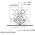
図7(a)の格子パターン2000は、その中心から離間するほど、格子ピッチが大きくなる、というものである。このような分布が生まれるのは、二次元スケール2000の格子パターンを、図8の如き露光装置を用いて製造しているためである。
<Reason for two-dimensional grid pattern>
In the
図8の露光装置は、2つの光束を用いて干渉露光方式により感光性の材料(以下、「感光材料」という)の表面に干渉パターンを露光する装置である。そして、感光材料210の表面に露光された干渉パターンが回折格子スケール2000となる。
The exposure device of FIG. 8 is a device that exposes an interference pattern on the surface of a photosensitive material (hereinafter, referred to as “photosensitive material”) by an interference exposure method using two light beams. Then, the interference pattern exposed on the surface of the
図8に示すように、露光装置200は、可干渉光源である光源201と、分配器202と、第1のミラー204と、第2のミラー205と、第1のレンズ206と、第2のレンズ207と、第3のレンズ208と、第4のレンズ209とから構成されている。
As shown in FIG. 8, the
光源201から出射した光束Laは、分配器202によって第1の光束Lb1と、第2の光束Lb2と分けられる。第1の光束Lb1は、第1のミラー204に入射し、第2の光束Lb2は、第2のミラー205に入射する。
The luminous flux La emitted from the
第1のミラー204とスケール2の間には、第1のレンズ206と、第2のレンズ207が配置されている。また、第2のミラー205とスケール2の間には、第3のレンズ208と、第4のレンズ209が配置されている。
A
第1のミラー204に入射した第1の光束Lb1は、第1のミラー204によって反射され、第1のレンズ206及び第2のレンズ207を介して感光材料210の表面に入射する。また、第2のミラー205に入射した第2の光束Lb2は、第2のミラー205によって反射され、第3のレンズ208及び第4のレンズ209を介して感光材料210表面に入射する。
The first luminous flux Lb1 incident on the
第1の光束Lb1は、第1のレンズ206及び第2のレンズ207によって波面が平面な平面波に変換されて感光材料210に入射する。また、第2の光束Lb2は、第3のレンズ208及び第4のレンズ209によって波面が第1の光束Lb1の波面に対して所定の収差を有する平面波に変換されて感光材料210に入射する。第1の光束Lb1と第2の光束Lb2が重なり合い、所望の周期を有する干渉縞パターンが感光材料210の表面に形成される。そして、感光材料210の表面が干渉縞パターンに沿って露光されることで、回折格子スケール2000が形成される。
The first light flux Lb1 is converted into a plane wave whose wavefront is flat by the
第1の光束は平面波に近似され得るが、実際には球面波であり、平面波と異なる分だけ、その誤差の影響は、中心から離れる部分ほど、カウントの計数感度を弱くする。 Although the first luminous flux can be approximated to a plane wave, it is actually a spherical wave, and the influence of the error is weaker as the count is closer to the center because it is different from the plane wave.
図9は、図8の露光装置が、図9の実線の正方形格子パターンを描画しようとするときに、球面波による回折現象により、図9の実線の正方形格子パターンが、図9の破線で示された「歪んだ」格子パターンに形状が変えられてしまう様子を説明している。 In FIG. 9, when the exposure apparatus of FIG. 8 tries to draw the square grid pattern of the solid line of FIG. 9, the square grid pattern of the solid line of FIG. 9 is shown by the broken line of FIG. 9 due to the diffraction phenomenon by the spherical wave. Explains how the shape is transformed into a distorted "distorted" grid pattern.
即ち、図9のような、周辺部ほど歪みが大きくピッチも拡がる二次元スケールの変位検出によって得た「変位」の位置情報は、位置情報自体に誤差を含んでいることとなる。図9の格子パターンに歪みが存在することは、変位検出装置が検出した、検出対象の変位や位置の情報に補正を加える必要があることを意味する。 That is, the position information of "displacement" obtained by the displacement detection of the two-dimensional scale in which the distortion is larger and the pitch is wider toward the peripheral portion as shown in FIG. 9 includes an error in the position information itself. The presence of distortion in the grid pattern of FIG. 9 means that it is necessary to correct the displacement and position information of the detection target detected by the displacement detection device.
<変位検出装置>…第3実施形態
図7の二次元スケールと、この二次元スケールを組み込んだ変位検出装置(図10)が上述の問題に対処する「補正」を実現する。図10において、本実施形態の変位検出装置3000は、図7の二次元スケール2000と連携して種々の処理を行う。
<Displacement detection device> ... Third embodiment The two-dimensional scale of FIG. 7 and the displacement detection device (FIG. 10) incorporating the two-dimensional scale realize "correction" for dealing with the above-mentioned problem. In FIG. 10, the
本実施形態の変位検出装置と連携する二次元スケール2000には、前述したように3つのヘッド(2210,2220,2230)が組み込まれている。これらのうち、ヘッド(2220,2230)の光学系の構成、性能、動作は実質的に同じなので、図11の光学系によって代表させて説明する。これらの説明によりヘッド光学系が実質的にcos信号と、sin信号を出力することが理解される。原点マーク読取ヘッド2210は、周知のレンズが1枚の光学系である。
As described above, three heads (2210, 2220, 2230) are incorporated in the two-
図11において、読取ヘッド光学系は、光源20と、レンズ11と、対照的位置に配置された2つの反射部12、13と、対照的位置に配置された2つのミラー14、16と、1つのビームスプリッタ17と、対照的位置に配置された2つの受光部18、19とを有している。
In FIG. 11, the reading head optical system includes a
光源20は、二次元スケール格子面に対して略垂直に配置されている。光源20と二次元スケール格子面との間に配置されたレンズ11は、光源20から照射された光Lを任意の径に集光する。光源20から照射された光Lは、レンズ11を介して二次元スケール格子面の回折格子のスポットOに照射される。回折格子に照射された光Lは、当該回折格子によって1回目の回折(反射)がなされ、これにより、回折格子に照射された光Lは、正の次数を有する1回目の回折が行われた回折光(以下、「1回回折光」という)L1と、負の次数を有する1回回折光−L1に分けられる。
The
2つの反射部12、13は、光源20を間に挟むようにして、第1の計測方向X1に沿って配置されている。図11の紙面右側の反射部12には、回折格子によって1回回折された正の次数を有する1回回折光L1が入射し、紙面左側の反射部13には、回折格子によって1回回折された負の次数を有する1回回折光−L1が入射する。反射部12は、入射した1回回折光L1を反射部12内で2回反射させて再び回折格子のスポットOに照射する。また、反射部13は、入射した1回回折光−L1を反射部13内で2回反射させて再び同じスポットOに照射する。
The two reflecting
反射部12によって再び回折格子へ入射した正の次数を有する1回回折光L1は、回折格子によって2回目の回折が行われ、正の次数を有する2回目の回折が行われた回折光(以下、「2回回折光」という)L2として回折格子から出射される。また、反射部13によって回折格子へ再度入射させられた負の次数を有する1回回折光−L1は、回折格子によって2回目の回折が行われ、負の次数を有する2回回折光−L2として回折格子から出射される。
The first diffracted light L1 having a positive order incident on the diffractive grid again by the reflecting
ミラー14、16は、光源20を間に挟むようにして、計測方向X1に沿って配置されている。紙面右側のミラー14には、正の次数を有する2回回折光L2が入射し、左側のミラー16には、負の次数を有する2回回折光−L2が入射する。ミラー14は、入射した2回回折光L2をビームスプリッタ17に向けて反射し、一方、ミラー16は、入射した2回回折光−L2をビームスプリッタ17に向けて反射する。
The
光源20の、回折格子に対して反対上方には、ビームスプリッタ17が配置されている。このビームスプリッタ17は、第1のミラー14および第2のミラー16から反射された2つの2回回折光L2、−L2を重ね合わせて干渉光を得る。さらに、ビームスプリッタ17は、干渉光を第1の干渉光Ld1と第2の干渉光Ld2の2つに分割し、出射する。そして、このビームスプリッタ17における第1の干渉光Ld1の出射口には、第1の受光部18が設けられており、ビームスプリッタ17における第2の干渉光Ld2の出射口には、第2の受光部19が設けられている。受光部18,19は、夫々の光信号を光電変換して、ケーブル(不図示)を介して、図10の変位検出部にsin信号、cos信号として送られる。
A
図10に戻って、X方向の読取ヘッド2220から読み取られたsin信号、cos信号はX演算部2320に送られ、X方向変位量の計算、X方向絶対位置の演算、内挿処理などを行う。X演算部2320は、受信したsin信号、cos信号中のゼロクロス位置をインクリメンタル信号として抽出すると共に、絶対位置演算部2310から受けとったX原点マーク信号に基づいて、X絶対位置を演算する。
Returning to FIG. 10, the sin signal and cos signal read from the
Y方向の読取ヘッド2230から読み取られたsin信号、cos信号はY演算部2330に送られ、Y方向変位量の計算、X方向絶対位置の演算、内挿処理などを行う。
The sin signal and cos signal read from the
原点マーク読取ヘッド2210が検出した原点信号は絶対位置演算部2310に送られ、絶対位置演算部2310は、絶対位置が検出されたことををX方向変位量演算部2320およびY方向変位量演算部2330に送る。
The origin signal detected by the origin
また、X方向変位量演算部2320は、数式(1)の式で、Y方向の絶対位置を求めるための、Y方向位置Y(n)における、基準原点マーク列1202との交叉位置から、傾斜原点マーク列1201との交差点までのヘッド移動距離D[Y(n)]を計算し、このデータを、Y方向変位量演算部2330に送って、Y方向変位量演算部2330でのY絶対位置(Yabs)の計算を行わせる。
Further, the displacement
このような3つの演算部での連係動作により、X方向絶対位置と、Y方向絶対位置とが計算される。 The absolute position in the X direction and the absolute position in the Y direction are calculated by the linked operation of the three calculation units.
なお、この段階で計算されたX方向絶対位置と、Y方向絶対位置とは、二次元スケール2000の格子列が歪んでいることによる絶対位置における誤差が補正される前の絶対位置XabsとYabsとである。
The absolute position in the X direction and the absolute position in the Y direction calculated at this stage are the absolute positions Xabs and Yabs before the error in the absolute position due to the distortion of the grid array of the two-
<内挿処理について>
ヘッドが出力するsin信号、cos信号に関連して、演算部で行われる内挿を説明する。
<About interpolation processing>
Interpolation performed by the arithmetic unit in relation to the sin signal and cos signal output by the head will be described.
図11において、受光部18では、干渉光Ldを受信し、光電変換することで、Acos(4KΔx+δ)の干渉信号を得る。Aは、干渉の振幅であり、Kは2π/tで示される波数である。また、Δxは、検出ヘッドの計測方向X1の移動量を示しており、δは、初期位相を示している。ここで、本実施形態の変位検出装置の読取ヘッド光学系では、光源20から照射された光Lを回折格子によって正の次数の1回回折光L1と、負の次数の1回回折光−L1に分けている。さらに、回折格子によって2回の回折(2K)を行い、ビームスプリッタ17によって2つの2回回折した回折光L2、−L2を重ね合わせている(2K+2K=4K)。そのため、上述した干渉信号のようにxの移動量に4Kをかけることになる。
In FIG. 11, the
よって、二次元スケール2000の格子面のある回折格子に対して読取ヘッド光学系が計測方向X1に相対的に移動すると、回折格子の1ピッチあたり、4つの波、すなわち4回の光の明暗が受光部18によって得ることができる。これにより、高分解能の変位検出が可能となる。
Therefore, when the reading head optical system moves relative to the measurement direction X1 with respect to a diffraction grating having a lattice plane of the two-
なお、受光部19によって得られる信号は、受光部18によって得られる干渉信号に対して90度位相が異なっている。これにより、sin信号とcos信号とを得ることができる。そして、このsin信号とcos信号とが、変位検出装置3000のY方向変位量演算部2330などへ出力される、ことは前述したとおりである。
The signal obtained by the
<Y方向での絶対位置演算>
第1実施形態乃至第3実施形態に特徴の1つはY方向の原点マークの検出は行わず、Y方向変位量演算部2330では、インクリメンタル信号の演算に留まる。即ち、Y方向変位量演算部2330は、相対的なn位置における位置Y(n)をインクリメンタル信号の離散的位置毎に計算することはできる。また、Y方向変位量演算部2330は、sin信号とcos信号とに基づいて内挿演算はできるので、クロス処理で検出した分解能の低いY位置に留まらず、内挿によって計算したY位置を相対位置の離散的な座標値として計算できる。
<Absolute position calculation in the Y direction>
One of the features of the first to third embodiments is that the origin mark in the Y direction is not detected, and the displacement
ある特定の相対位置Y(n)について、その原点信号検出部2310は、数式(1)に従って、そのY(n)の絶対位置を計算することができる。 For a specific relative position Y (n), the origin signal detection unit 2310 can calculate the absolute position of the Y (n) according to the equation (1).
相対位置Y(n)と絶対位置Yabs(n)との間のずれは、あらゆるnについてバラバラになることはないため、絶対位置演算部2310でY方向絶対位置が計算された時のY方向相対位置とのずれ量を求め、このずれ量を他のY方向相対位置に適用することで、Y方向における相対位置に基づいた絶対位置Yabsを求めることができる。 Since the deviation between the relative position Y (n) and the absolute position Yabs (n) does not become different for every n, the Y direction relative when the absolute position calculation unit 2310 calculates the absolute position in the Y direction. By obtaining the amount of deviation from the position and applying this amount of deviation to other relative positions in the Y direction, the absolute position Yabs based on the relative position in the Y direction can be obtained.
<絶対位置の補正>
本実施形態の二次元スケールは図9などに示すように、格子の形状が二次関数近似による変調がなされているために、この変調により、格子形状に理論値との誤差がある。3つのヘッドが検出するsin信号、cos信号にはこの誤差が乗っており、この誤差は、演算部が出力するXY絶対位置にも包含されており、除去は必須である。
<Absolute position correction>
In the two-dimensional scale of the present embodiment, as shown in FIG. 9, the shape of the lattice is modulated by quadratic function approximation, and therefore, the lattice shape has an error from the theoretical value due to this modulation. This error is included in the sin signal and cos signal detected by the three heads, and this error is also included in the XY absolute position output by the calculation unit, and removal is essential.
本実施形態の補正部2400は、この誤差による絶対位置データに対する補正を行う。
The
誤差の発生原因を図12Aおよび図12Bなどにしたがって説明する。図12Aおよび図12Bにおいて、格子ピッチが一定値Cである格子列が、球面波による回折により、格子ピッチが二次関数:
図9は、補正の手法を概念的に説明している。 FIG. 9 conceptually describes the correction method.
即ち、図9では、カウント(計数)が10刻みになる2次元スケールでの座標をプロットしている。実際に、中心の(10,10)の位置では、リニアスケールでは(10,10)の座標値を有するが、二次元スケールでは(8,8)の座標値を有している。そのため、二次元スケールでX=10,Y=10とカウントされた座標は、リニアスケールでは、X=8,Y=8の座標位置に相当することを意味する。これは、座標系の座標軸の目盛の、球面波を表す二次関数によって写像を行って変換することに等しい。 That is, in FIG. 9, the coordinates on the two-dimensional scale in which the count is in increments of 10 are plotted. In fact, the central (10,10) position has the coordinate value of (10,10) on the linear scale, but has the coordinate value of (8,8) on the two-dimensional scale. Therefore, the coordinates counted as X = 10 and Y = 10 on the two-dimensional scale mean that they correspond to the coordinate positions of X = 8 and Y = 8 on the linear scale. This is equivalent to mapping and transforming by a quadratic function representing a spherical wave on the scale of the coordinate axes of the coordinate system.
具体的には、二次元スケールは2つの座標軸を有するから、2種類の目盛(X目盛およびY目盛)を有するので、このX目盛とY目盛との目盛値(1目盛の距離)を補正すればよい。 Specifically, since the two-dimensional scale has two coordinate axes, it has two types of scales (X scale and Y scale), so the scale value (distance of one scale) between the X scale and the Y scale should be corrected. Just do it.
図10に戻って、X方向補正値データCxはメモリ2350に、Y方向補正値データCyはメモリ2340に前もって記憶されている。これらのメモリ2350,2340は、通常のメモリと同じく、列(縦)方向のメモリアドレスカウンタと、行(横)方向のアドレスカウンタを有する。この実施形態では、XY方向と行列方向に関連性は全くない。以下の組合せは一例である。即ち、図10の装置では、Y補正データメモリ2340の:
列アドレスカウンタには補正前のY方向絶対位置情報Yabs、
行アドレスカウンタには補正前のX方向絶対位置情報Xabs、
が入力される。同じく、X補正データメモリ2350の:
列アドレスカウンタには補正前のY方向絶対位置情報Yabs、
行アドレスカウンタには補正前のX方向絶対位置情報Xabs、
が入力される。換言すれば、補正データCy用メモリ2340と補正データCx用メモリ2350のアドレッシングは、共に、補正前の、X絶対位置XabsとY絶対位置Yabsとである。
Returning to FIG. 10, the X-direction correction value data Cx is stored in the
The column address counter has the absolute position information in the Y direction before correction Yabs,
The row address counter has the absolute position information Xabs in the X direction before correction,
Is entered. Similarly, of the X correction data memory 2350:
The column address counter has the absolute position information in the Y direction before correction Yabs,
The row address counter has the absolute position information Xabs in the X direction before correction,
Is entered. In other words, the addressing of the correction
補正前絶対位置情報(Xabs、Yabs)の(補正データ)メモリ2350,2340から読み出した補正データは、
Cx(Xabs、Yabs)
Cy(Xabs、Yabs)
となる。補正部2400では、補正後の絶対位置を:
補正前X絶対位置+Cx(Xabs、Yabs)
補正前Y絶対位置+Cy(Xabs、Yabs)
に従って計算される。
The correction data read from the (correction data)
Cx (Xabs, Yabs)
Cy (Xabs, Yabs)
Will be. In the
Before correction X absolute position + Cx (Xabs, Yabs)
Y absolute position before correction + Cy (Xabs, Yabs)
It is calculated according to.
図9の歪みの例について計算した補正データメモリの例を図13Aおよび図13Bに示す。 An example of the correction data memory calculated for the example of distortion in FIG. 9 is shown in FIGS. 13A and 13B.
<データ補正の変形>
本実施形態のデータメモリは、サンプリングは10毎に行っていたが、所望の分解能に応じてさらに細かく、或いは、粗くすることは可能である。なお、球面波で露光した二次元スケールを説明したが、平面波で露光した2次元リニアスケールにしてもよい。
<Transformation of data correction>
In the data memory of the present embodiment, sampling is performed every 10, but it is possible to make the data memory finer or coarser depending on the desired resolution. Although the two-dimensional scale exposed by the spherical wave has been described, the two-dimensional linear scale exposed by the plane wave may be used.
[他の実施形態]
以上、実施形態を参照して本願発明を説明したが、本願発明は上記実施形態に限定されるものではない。本願発明の構成や詳細には、本願発明のスコープ内で当業者が理解し得る様々な変更をすることができる。また、それぞれの実施形態に含まれる別々の特徴を如何様に組み合わせたシステムまたは装置も、本発明の範疇に含まれる。
[Other Embodiments]
Although the invention of the present application has been described above with reference to the embodiment, the invention of the present application is not limited to the above embodiment. Various changes that can be understood by those skilled in the art can be made within the scope of the present invention in terms of the structure and details of the present invention. Also included in the scope of the present invention are systems or devices in any combination of the different features contained in each embodiment.
また、本発明は、複数の機器から構成されるシステムに適用されてもよいし、単体の装置に適用されてもよい。さらに、本発明は、実施形態の機能を実現する情報処理プログラムが、システムあるいは装置に直接あるいは遠隔から供給される場合にも適用可能である。したがって、本発明の機能をコンピュータで実現するために、コンピュータにインストールされるプログラム、あるいはそのプログラムを格納した媒体、そのプログラムをダウンロードさせるWWW(World Wide Web)サーバも、本発明の範疇に含まれる。特に、少なくとも、上述した実施形態に含まれる処理ステップをコンピュータに実行させるプログラムを格納した非一時的コンピュータ可読媒体(non-transitory computer readable medium)は本発明の範疇に含まれる。 Further, the present invention may be applied to a system composed of a plurality of devices, or may be applied to a single device. Furthermore, the present invention is also applicable when the information processing program that realizes the functions of the embodiment is supplied directly or remotely to the system or device. Therefore, in order to realize the functions of the present invention on a computer, a program installed on the computer, a medium containing the program, and a WWW (World Wide Web) server for downloading the program are also included in the scope of the present invention. .. In particular, at least a non-transitory computer readable medium containing a program that causes a computer to execute the processing steps included in the above-described embodiment is included in the scope of the present invention.
Claims (7)
前記基準原点マーク列と非平行となるように傾斜角度を付けて設けられた第1傾斜原点マーク列と、
前記基準原点マーク列と第1傾斜原点マーク列と非平行となる第2傾斜原点マーク列と、
を含むリニアスケールと、
前記リニアスケール上を走査し、前記基準原点マーク列と前記第1傾斜原点マーク列と前記第2傾斜原点マーク列と交差して前記基準原点マーク列を読み取る読取ヘッドと、
を具備するスケール装置。 The coordinate origin of the X-axis a shown to reference origin mark row, and the reference origin mark rows extending in the Y-axis direction orthogonal to the X-axis direction,
A first inclined origin mark train provided with a tilt angle such that the reference origin mark column and non-parallel,
A second tilt origin mark sequence that is non-parallel to the reference origin mark sequence and the first tilt origin mark sequence,
With linear scale including
Said scanning the linear scale, the readhead reads the reference origin mark train crosses the reference origin mark train and the first inclined origin mark row and the second inclined origin mark train,
A scale device equipped with.
前記読取ヘッドは、前記リニアスケールをX軸方向に走査して、X軸方向についての現走査位置を示す相対位置信号を出力し、前記Y軸方向の任意のY座標位置に移動可能に配置されており、
この二軸変位検出装置は、
前記任意のY座標位置おいて、前記読取ヘッドが、前記リニアスケールを前記X軸方向に走査して、前記基準原点マーク列と前記第1傾斜原点マーク列と前記第2傾斜原点マーク列と交差した場合に、前記任意のY軸位置における基準原点マーク列と前記第1、第2傾斜原点マーク列のそれぞれとの間の距離を計数する手段と、
前記距離に応じて、前記任意のY軸位置での絶対的Y軸位置を算出する手段と、
を具備する二軸変位検出装置。 A biaxial displacement detection device to which the scale device according to any one of claims 1 to 3 is connected.
The read head, the linear scale is scanned in the X-axis direction, and outputs a relative position signal indicating the current scanning position of the X-axis direction, is movably arranged in an arbitrary Y coordinate position of the Y-axis direction And
This biaxial displacement detector is
At the arbitrary Y coordinate position, the reading head scans the linear scale in the X-axis direction and intersects the reference origin mark row, the first tilt origin mark row, and the second tilt origin mark row. when, means for counting a distance between the arbitrary reference origin mark row and the first that put the Y-axis position, each of the second inclined origin mark train,
Depending on the distance, and means for calculating the absolute Y-axis position in the arbitrary Y-axis position,
A biaxial displacement detection device comprising.
前記リニアスケールの製造公差に起因する前記相対位置信号の誤差を補正する補正データを、前記リニアスケールの製造時点で記憶する第1メモリと、
前記リニアスケールを走査して前記読取ヘッドが検出したX軸および/またはY軸の相対位置信号を、前記読取ヘッドが前記基準原点マーク列と前記第1、第2傾斜原点マーク列とを読み出して検出したX軸および/またはY軸の原点信号に従って、Y軸の絶対位置信号に変換すると共に、変換した絶対位置信号に基づいて前記第1メモリから前記補正データを読み出して、読み出した前記補正データを、前記変換した絶対位置信号に適用して、補正後の絶対位置情報として出力する補正手段と、
を具備する請求項4に記載の二軸変位検出装置。 The biaxial displacement detection device is
A first memory that stores correction data for correcting an error in the relative position signal due to the manufacturing tolerance of the linear scale at the time of manufacturing the linear scale, and
The reading head reads the X-axis and / or Y-axis relative position signals detected by the reading head by scanning the linear scale, and the reading head reads the reference origin mark sequence and the first and second tilted origin mark sequences. accordance origin signal of the detected X-axis and / or Y-axis, and converts the absolute position signal of the Y-axis, reads the correction data from the first memory based on the converted absolute position signal, the read said correction A correction means that applies data to the converted absolute position signal and outputs it as corrected absolute position information.
The biaxial displacement detection device according to claim 4.
前もって、所定の時点で計測した前記任意のY軸位置における前記基準原点マーク列と前記第1、第2傾斜原点マーク列のそれぞれとの間の距離を記憶している第2メモリと、
任意の時点で算出した前記距離と、前記第2メモリに記憶された前記距離とに基づいて、前記読取ヘッドもしくは前記リニアスケールのいずれかがX軸に対して傾いているか否かを判断する手段と、
を具備した請求項4又は5に記載の二軸変位検出装置。 The biaxial displacement detection device further includes
Beforehand, a second memory which stores the distance between the reference origin mark train and the first, each of the second inclined origin mark column in the arbitrary Y-axis position measured at a given time,
A means for determining whether or not either the reading head or the linear scale is tilted with respect to the X axis based on the distance calculated at an arbitrary time point and the distance stored in the second memory. When,
The biaxial displacement detection device according to claim 4 or 5.
Priority Applications (3)
| Application Number | Priority Date | Filing Date | Title |
|---|---|---|---|
| JP2017088413A JP6875923B2 (en) | 2017-04-27 | 2017-04-27 | Scale device and biaxial displacement detector |
| DE102018108882.5A DE102018108882A1 (en) | 2017-04-27 | 2018-04-13 | Scale device and biaxial displacement detection device |
| US15/957,660 US10634521B2 (en) | 2017-04-27 | 2018-04-19 | Scale device and two-axis displacement detection device |
Applications Claiming Priority (1)
| Application Number | Priority Date | Filing Date | Title |
|---|---|---|---|
| JP2017088413A JP6875923B2 (en) | 2017-04-27 | 2017-04-27 | Scale device and biaxial displacement detector |
Publications (3)
| Publication Number | Publication Date |
|---|---|
| JP2018185272A JP2018185272A (en) | 2018-11-22 |
| JP2018185272A5 JP2018185272A5 (en) | 2020-01-30 |
| JP6875923B2 true JP6875923B2 (en) | 2021-05-26 |
Family
ID=63797215
Family Applications (1)
| Application Number | Title | Priority Date | Filing Date |
|---|---|---|---|
| JP2017088413A Active JP6875923B2 (en) | 2017-04-27 | 2017-04-27 | Scale device and biaxial displacement detector |
Country Status (3)
| Country | Link |
|---|---|
| US (1) | US10634521B2 (en) |
| JP (1) | JP6875923B2 (en) |
| DE (1) | DE102018108882A1 (en) |
Families Citing this family (3)
| Publication number | Priority date | Publication date | Assignee | Title |
|---|---|---|---|---|
| DE102016214456A1 (en) * | 2016-08-04 | 2018-02-08 | Dr. Johannes Heidenhain Gesellschaft Mit Beschränkter Haftung | Position measuring device and method for operating a position measuring device |
| DE102020118659A1 (en) * | 2019-07-17 | 2021-01-21 | Dmg Mori Co., Ltd. | DETECTION DEVICE |
| EP3789735B1 (en) * | 2019-09-04 | 2021-11-10 | Dr. Johannes Heidenhain GmbH | Position measuring device |
Family Cites Families (11)
| Publication number | Priority date | Publication date | Assignee | Title |
|---|---|---|---|---|
| JPS5023618B1 (en) | 1970-05-20 | 1975-08-08 | ||
| JPS5246093B2 (en) | 1973-07-02 | 1977-11-21 | ||
| DE3542514A1 (en) * | 1985-12-02 | 1987-06-04 | Zeiss Carl Fa | MEASURING DEVICE |
| US6649925B2 (en) * | 1999-11-26 | 2003-11-18 | Amos Talmi | Methods of calibrating a position measurement device |
| JP4404184B2 (en) * | 2002-11-18 | 2010-01-27 | ソニーマニュファクチュアリングシステムズ株式会社 | Displacement detector |
| DE102008010284A1 (en) * | 2008-02-21 | 2009-08-27 | Dr. Johannes Heidenhain Gmbh | XY table with a measuring arrangement for position determination |
| JP5126287B2 (en) * | 2010-05-31 | 2013-01-23 | 株式会社安川電機 | Linear encoder, linear motor, linear motor system |
| JP6245941B2 (en) * | 2012-12-10 | 2017-12-13 | Dmg森精機株式会社 | Displacement detector |
| EP3306273B1 (en) * | 2014-12-04 | 2020-02-05 | Hexagon Technology Center GmbH | Capacitive linear encoder |
| EP3064902B1 (en) * | 2015-03-06 | 2017-11-01 | Hexagon Technology Center GmbH | System for determining positions |
| JP6361760B2 (en) | 2017-02-27 | 2018-07-25 | ブラザー工業株式会社 | Image recording device |
-
2017
- 2017-04-27 JP JP2017088413A patent/JP6875923B2/en active Active
-
2018
- 2018-04-13 DE DE102018108882.5A patent/DE102018108882A1/en active Pending
- 2018-04-19 US US15/957,660 patent/US10634521B2/en active Active
Also Published As
| Publication number | Publication date |
|---|---|
| US20180313671A1 (en) | 2018-11-01 |
| US10634521B2 (en) | 2020-04-28 |
| DE102018108882A1 (en) | 2018-10-31 |
| JP2018185272A (en) | 2018-11-22 |
Similar Documents
| Publication | Publication Date | Title |
|---|---|---|
| JP5147367B2 (en) | Encoder | |
| JP5147368B2 (en) | Encoder | |
| US8822907B2 (en) | Optical position-measuring device having two crossed scales | |
| JP4246071B2 (en) | Method for determining and correcting guidance errors in coordinate measuring machines. | |
| JP6875923B2 (en) | Scale device and biaxial displacement detector | |
| JP5804899B2 (en) | Optical angle measuring device | |
| US6914235B2 (en) | Position measuring system and method for operating a position measuring system | |
| US7586621B2 (en) | Displacement-measuring optical scale and optical encoder using same | |
| US7112782B2 (en) | Optical position measuring system | |
| JP7222081B2 (en) | Linear and rotary multi-track absolute position encoder and method of using same | |
| US10190893B2 (en) | Encoder | |
| US10859374B2 (en) | Optical angle sensor | |
| US7161139B2 (en) | Position-measuring system and method for operating a position-measuring system | |
| US11353583B2 (en) | Optical position-measurement device with varying focal length along a transverse direction | |
| JP2005502036A5 (en) | ||
| EP2955490B1 (en) | Displacement detecting device | |
| JP2016130728A (en) | Optical position measurement device | |
| US7196319B2 (en) | Position-measuring device | |
| JP4494189B2 (en) | Accuracy measurement method and calibration method of non-contact image measuring machine | |
| JP2011145150A (en) | Method of designing optical encoder | |
| JP7066189B2 (en) | Absolute position measuring device and absolute position measuring method | |
| JPH08285527A (en) | Device and method for detecting displacement | |
| JP2016166874A (en) | Optical angle measurement device | |
| JP2009270945A (en) | Optical measuring device and alignment system |
Legal Events
| Date | Code | Title | Description |
|---|---|---|---|
| A521 | Request for written amendment filed |
Free format text: JAPANESE INTERMEDIATE CODE: A523 Effective date: 20191211 |
|
| A621 | Written request for application examination |
Free format text: JAPANESE INTERMEDIATE CODE: A621 Effective date: 20191211 |
|
| A977 | Report on retrieval |
Free format text: JAPANESE INTERMEDIATE CODE: A971007 Effective date: 20201221 |
|
| A131 | Notification of reasons for refusal |
Free format text: JAPANESE INTERMEDIATE CODE: A131 Effective date: 20210105 |
|
| A521 | Request for written amendment filed |
Free format text: JAPANESE INTERMEDIATE CODE: A523 Effective date: 20210308 |
|
| TRDD | Decision of grant or rejection written | ||
| A01 | Written decision to grant a patent or to grant a registration (utility model) |
Free format text: JAPANESE INTERMEDIATE CODE: A01 Effective date: 20210406 |
|
| A61 | First payment of annual fees (during grant procedure) |
Free format text: JAPANESE INTERMEDIATE CODE: A61 Effective date: 20210423 |
|
| R150 | Certificate of patent or registration of utility model |
Ref document number: 6875923 Country of ref document: JP Free format text: JAPANESE INTERMEDIATE CODE Ref document number: 6875923 Country of ref document: JP Free format text: JAPANESE INTERMEDIATE CODE: R150 |
|
| R250 | Receipt of annual fees |
Free format text: JAPANESE INTERMEDIATE CODE: R250 |