EP1923673B1 - Position measuring device - Google Patents
Position measuring device Download PDFInfo
- Publication number
- EP1923673B1 EP1923673B1 EP07019810.6A EP07019810A EP1923673B1 EP 1923673 B1 EP1923673 B1 EP 1923673B1 EP 07019810 A EP07019810 A EP 07019810A EP 1923673 B1 EP1923673 B1 EP 1923673B1
- Authority
- EP
- European Patent Office
- Prior art keywords
- scanning
- incremental
- measuring device
- reference pulse
- position measuring
- Prior art date
- Legal status (The legal status is an assumption and is not a legal conclusion. Google has not performed a legal analysis and makes no representation as to the accuracy of the status listed.)
- Active
Links
- 238000003384 imaging method Methods 0.000 claims description 37
- 230000007274 generation of a signal involved in cell-cell signaling Effects 0.000 claims description 34
- 239000000463 material Substances 0.000 claims description 31
- 230000003287 optical effect Effects 0.000 claims description 27
- 238000005259 measurement Methods 0.000 claims description 19
- 230000000737 periodic effect Effects 0.000 claims description 10
- 238000005286 illumination Methods 0.000 claims description 6
- 230000007935 neutral effect Effects 0.000 description 23
- 238000005070 sampling Methods 0.000 description 10
- 238000013461 design Methods 0.000 description 5
- 238000012986 modification Methods 0.000 description 4
- 230000004048 modification Effects 0.000 description 4
- 238000012545 processing Methods 0.000 description 3
- 230000005855 radiation Effects 0.000 description 3
- 230000015572 biosynthetic process Effects 0.000 description 2
- 230000001419 dependent effect Effects 0.000 description 2
- 230000000694 effects Effects 0.000 description 2
- 230000002452 interceptive effect Effects 0.000 description 2
- 239000007787 solid Substances 0.000 description 2
- 230000005540 biological transmission Effects 0.000 description 1
- 238000011109 contamination Methods 0.000 description 1
- 238000006073 displacement reaction Methods 0.000 description 1
- 230000010354 integration Effects 0.000 description 1
- 238000004519 manufacturing process Methods 0.000 description 1
- 238000013507 mapping Methods 0.000 description 1
- 239000003550 marker Substances 0.000 description 1
- 230000001902 propagating effect Effects 0.000 description 1
- 238000000926 separation method Methods 0.000 description 1
- 230000001629 suppression Effects 0.000 description 1
Images


Classifications
-
- G—PHYSICS
- G01—MEASURING; TESTING
- G01D—MEASURING NOT SPECIALLY ADAPTED FOR A SPECIFIC VARIABLE; ARRANGEMENTS FOR MEASURING TWO OR MORE VARIABLES NOT COVERED IN A SINGLE OTHER SUBCLASS; TARIFF METERING APPARATUS; MEASURING OR TESTING NOT OTHERWISE PROVIDED FOR
- G01D5/00—Mechanical means for transferring the output of a sensing member; Means for converting the output of a sensing member to another variable where the form or nature of the sensing member does not constrain the means for converting; Transducers not specially adapted for a specific variable
- G01D5/26—Mechanical means for transferring the output of a sensing member; Means for converting the output of a sensing member to another variable where the form or nature of the sensing member does not constrain the means for converting; Transducers not specially adapted for a specific variable characterised by optical transfer means, i.e. using infrared, visible, or ultraviolet light
- G01D5/32—Mechanical means for transferring the output of a sensing member; Means for converting the output of a sensing member to another variable where the form or nature of the sensing member does not constrain the means for converting; Transducers not specially adapted for a specific variable characterised by optical transfer means, i.e. using infrared, visible, or ultraviolet light with attenuation or whole or partial obturation of beams of light
- G01D5/34—Mechanical means for transferring the output of a sensing member; Means for converting the output of a sensing member to another variable where the form or nature of the sensing member does not constrain the means for converting; Transducers not specially adapted for a specific variable characterised by optical transfer means, i.e. using infrared, visible, or ultraviolet light with attenuation or whole or partial obturation of beams of light the beams of light being detected by photocells
- G01D5/36—Forming the light into pulses
- G01D5/38—Forming the light into pulses by diffraction gratings
-
- G—PHYSICS
- G01—MEASURING; TESTING
- G01D—MEASURING NOT SPECIALLY ADAPTED FOR A SPECIFIC VARIABLE; ARRANGEMENTS FOR MEASURING TWO OR MORE VARIABLES NOT COVERED IN A SINGLE OTHER SUBCLASS; TARIFF METERING APPARATUS; MEASURING OR TESTING NOT OTHERWISE PROVIDED FOR
- G01D5/00—Mechanical means for transferring the output of a sensing member; Means for converting the output of a sensing member to another variable where the form or nature of the sensing member does not constrain the means for converting; Transducers not specially adapted for a specific variable
- G01D5/12—Mechanical means for transferring the output of a sensing member; Means for converting the output of a sensing member to another variable where the form or nature of the sensing member does not constrain the means for converting; Transducers not specially adapted for a specific variable using electric or magnetic means
- G01D5/244—Mechanical means for transferring the output of a sensing member; Means for converting the output of a sensing member to another variable where the form or nature of the sensing member does not constrain the means for converting; Transducers not specially adapted for a specific variable using electric or magnetic means influencing characteristics of pulses or pulse trains; generating pulses or pulse trains
- G01D5/24428—Error prevention
- G01D5/24433—Error prevention by mechanical means
- G01D5/24438—Special design of the sensing element or scale
-
- G—PHYSICS
- G01—MEASURING; TESTING
- G01D—MEASURING NOT SPECIALLY ADAPTED FOR A SPECIFIC VARIABLE; ARRANGEMENTS FOR MEASURING TWO OR MORE VARIABLES NOT COVERED IN A SINGLE OTHER SUBCLASS; TARIFF METERING APPARATUS; MEASURING OR TESTING NOT OTHERWISE PROVIDED FOR
- G01D5/00—Mechanical means for transferring the output of a sensing member; Means for converting the output of a sensing member to another variable where the form or nature of the sensing member does not constrain the means for converting; Transducers not specially adapted for a specific variable
- G01D5/12—Mechanical means for transferring the output of a sensing member; Means for converting the output of a sensing member to another variable where the form or nature of the sensing member does not constrain the means for converting; Transducers not specially adapted for a specific variable using electric or magnetic means
- G01D5/244—Mechanical means for transferring the output of a sensing member; Means for converting the output of a sensing member to another variable where the form or nature of the sensing member does not constrain the means for converting; Transducers not specially adapted for a specific variable using electric or magnetic means influencing characteristics of pulses or pulse trains; generating pulses or pulse trains
- G01D5/245—Mechanical means for transferring the output of a sensing member; Means for converting the output of a sensing member to another variable where the form or nature of the sensing member does not constrain the means for converting; Transducers not specially adapted for a specific variable using electric or magnetic means influencing characteristics of pulses or pulse trains; generating pulses or pulse trains using a variable number of pulses in a train
- G01D5/2454—Encoders incorporating incremental and absolute signals
- G01D5/2455—Encoders incorporating incremental and absolute signals with incremental and absolute tracks on the same encoder
- G01D5/2457—Incremental encoders having reference marks
-
- G—PHYSICS
- G01—MEASURING; TESTING
- G01D—MEASURING NOT SPECIALLY ADAPTED FOR A SPECIFIC VARIABLE; ARRANGEMENTS FOR MEASURING TWO OR MORE VARIABLES NOT COVERED IN A SINGLE OTHER SUBCLASS; TARIFF METERING APPARATUS; MEASURING OR TESTING NOT OTHERWISE PROVIDED FOR
- G01D5/00—Mechanical means for transferring the output of a sensing member; Means for converting the output of a sensing member to another variable where the form or nature of the sensing member does not constrain the means for converting; Transducers not specially adapted for a specific variable
- G01D5/26—Mechanical means for transferring the output of a sensing member; Means for converting the output of a sensing member to another variable where the form or nature of the sensing member does not constrain the means for converting; Transducers not specially adapted for a specific variable characterised by optical transfer means, i.e. using infrared, visible, or ultraviolet light
- G01D5/32—Mechanical means for transferring the output of a sensing member; Means for converting the output of a sensing member to another variable where the form or nature of the sensing member does not constrain the means for converting; Transducers not specially adapted for a specific variable characterised by optical transfer means, i.e. using infrared, visible, or ultraviolet light with attenuation or whole or partial obturation of beams of light
- G01D5/34—Mechanical means for transferring the output of a sensing member; Means for converting the output of a sensing member to another variable where the form or nature of the sensing member does not constrain the means for converting; Transducers not specially adapted for a specific variable characterised by optical transfer means, i.e. using infrared, visible, or ultraviolet light with attenuation or whole or partial obturation of beams of light the beams of light being detected by photocells
- G01D5/36—Forming the light into pulses
- G01D5/366—Particular pulse shapes
Definitions
- the present invention relates to a position measuring device.
- Known position-measuring devices deliver not only periodic incremental signals with respect to the relative offset of two mutually movable objects but also so-called reference pulse signals.
- reference pulse signals By means of the reference pulse signals, an exact absolute reference with respect to the position of the two mutually movable objects can be established at certain predetermined reference positions along the measuring path. The usually significantly higher resolution incremental measurement can then be referred to the absolute position determined in this way.
- a common arrangement variant provides for arranging one or more reference markings laterally adjacent to the scanned incremental graduation track; this is about on the EP 194 611 A2 directed.
- Problematic such an arrangement proves that, in the case of the undesired rotation of the scanning unit and material measure about an axis perpendicular to the material scale ("moire rotation"), a shift in the position of the generated reference pulse signal with respect to the incremental signal results. An incorrect position determination is the result.
- the object of the present invention is to provide a position measuring device which is suitable for generating high-resolution incremental signals as well as for generating reference pulse signals at at least one reference position and which is as small as possible by possible Moire distortions of material measure and scanning unit is affected.
- a first position-measuring device for generating incremental signals and a reference-pulse signal at at least one reference position now comprises a scanning unit and a measuring standard movable in at least one measuring direction.
- the measuring graduation comprises two incremental graduation tracks extending in the measuring direction with periodic incremental divisions between which a reference marking track is arranged, which has a reference marking at at least one reference position.
- the scanning unit comprises first scanning means for generating the reference pulse signal and second scanning means for generating the incremental signals, wherein for generating the incremental signals each of the incremental divisions of a scanning beam is applied at least once in an incremental signal scanning field.
- the inventive design of the first position measuring device now ensures that even with a possible moire twisting of material measure and scanning unit no errors in the position determination result.
- the correct assignment of the generated reference pulse signal to the desired incremental signal period is always ensured since the incremental graduation tracks and the reference marking track have the same so-called neutral moiré axis, around which a possible rotation of the measuring scale and the scanning unit does not cause any erroneous measurement.
- a further advantage of the solution according to the invention is that relatively strong incremental signal amplitudes result even in the case of strong moire distortions of the material measure and the scanning unit. This is especially true in the further processing of the incremental signals, e.g. a possible interpolation of the same, of importance.
- the first position measuring device has a reference marking with a plurality of structural elements which are arranged mirror-symmetrically to an axis of symmetry which is oriented perpendicular to the measuring direction in the scale graduation plane.
- the structural elements of the reference marking are advantageously arranged mirror-symmetrically to an axis of symmetry (Sx) which extends parallel to the measuring direction (x) in the scale graduation plane.
- the reference marking on the material measure is preferably applied once in a reference pulse scanning field.
- the centers of the two incremental signal scanning fields and the center of the reference pulse scanning field lie, for example, on a straight line in the scale graduation plane which is oriented perpendicular to the measuring direction.
- the centers of the two incremental signal scanning fields lie on a straight line in the scale graduation plane which is oriented perpendicular to the measuring direction and the center of the reference pulse scanning field is arranged offset in the direction of measurement to this line on the measuring scale.
- the imaging optics in the scanning unit is dimensioned such that an image of the image-side focal plane of the structural elements results in the diaphragm plane, whereby the positional arrangement of the diaphragm apertures of the two diaphragm structures in the measuring direction is matched to the arrangement of the structural elements of the reference marker.
- the scanning unit further comprises a scanning plate on which the diaphragm structures and the imaging optics are arranged.
- the scanning unit comprises a scanning plate, on which the scanning gratings, the joining gratings and the reflector elements are arranged.
- the scanning unit is further associated with a light source which supplies the first and second scanning means with light for scanning the incremental graduations and the reference mark, and the scanning unit further comprises a splitting grid which converts the beam from the light source into a first sub-beam for the first reference pulse signal generating means and split a second sub-beam for the second scanning means for incremental signal generation.
- the splitting grid is designed such that a convergent illumination of the reference marking on the reflection measuring graduation results.
- the splitting grid can be arranged on the side of the scanning plate, which faces the material measure.
- a second position-measuring device for generating incremental signals and a reference-pulse signal at at least one reference position now comprises a scanning unit and a measuring graduation movable in at least one measuring direction for this purpose.
- the material measure comprises two reference marking tracks extending parallel to one another in the measuring direction, each of which has a reference marking on at least one reference position which is symmetrical with respect to an axis of symmetry are formed in the measuring direction. Between the reference mark tracks is arranged an incremental pitch track with a periodic incremental pitch.
- the scanning unit comprises first scanning means for generating the reference pulse signal, wherein for generating the reference pulse signal, the reference marks in the reference marking tracks of a scanning beam are applied at least once each in a reference pulse signal scanning field.
- second scanning means are provided in the scanning unit for generating the incremental signals, wherein for generating the incremental signals, the incremental graduation from a scanning beam in two incremental signal scanning fields is applied at least once in each case.
- the design of the second position-measuring device ensures that a reference-pulse signal can be generated with a width that corresponds to the width of the incremental signals. This is associated with a higher reliability of the position measuring devices.
- the reference markings are preferably mirror-symmetrical to an axis of symmetry which is oriented perpendicular to the measuring direction in the scale graduation plane.
- the centers of the two incremental signal scanning fields can lie on a first straight line in the measuring graduation plane oriented perpendicular to the measuring direction and the centers of the reference pulse scanning fields on a second straight line in the measuring graduation plane oriented perpendicular to the measuring direction, the two straight lines offset in the measuring direction to each other are arranged on the measuring scale.
- the reference markings are each formed as cylindrical lenses on the material measure, which have a transversal periodicity, so that the two first diffraction orders spatially separated from the illuminating scanning beam on a scanning in the scanning meet.
- the first scanning means in the scanning unit for generating the reference pulse signal preferably comprise a plurality of optical elements, among which a plurality of scanning gratings and reflector elements, via which a return reflection of the coming of a first reference pulse scanning field of the first reference mark track beam into a second reference pulse scanning field second reference mark track.
- the first scanning means comprise one or more reference pulse detector elements.
- the scanning unit can comprise a scanning plate, on whose side facing the measuring graduation a plurality of diffractive scanning gratings are arranged and on the opposite side a retroreflective roof prism is arranged, which has a plurality of mirrored surfaces as reflector elements.
- the second scanning means in the scanning unit for generating the incremental signals preferably comprise a plurality of optical elements, among which a plurality of scanning gratings, an optional joining grid and at least two reflector elements. Furthermore, the second scanning means comprise a plurality of incremental signal detector elements.
- a return reflection of the radiation beam coming from a first incremental signal scanning field preferably takes place via the reflector elements into a second incremental signal scanning field.
- the scanning unit further preferably comprises a scanning plate, on the side of which the measuring scale side is facing, a plurality of diffractive scanning gratings and an optional joining grating are arranged and on the opposite Side a retroreflective roof prism is arranged, which has a plurality of mirrored surfaces as reflector elements.
- the scanning unit is further associated with a light source which supplies the first and second scanning means with light for scanning the incremental pitch and the reference marks.
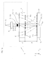
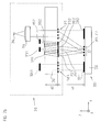
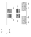
- FIGS. 1a and 1b show in strongly schematized form partial scanning beam paths for reference pulse signal generation in a first position-measuring device according to the invention in different views.
- Figure 1c shows schematic partial scanning beam paths for generating the incremental signals in this position measuring device.
- the sub-scanning beam paths for reference pulse signal generation are shown in solid lines, the sub-scanning beam paths for generating the incremental signals, however, each dashed lines.
- the illustrated first optical position-measuring device comprises a measuring graduation, designed as a reflection measuring graduation 30 and a scanning unit 10 movable in at least one measuring direction x.
- the reflection measuring graduation 30 and the scanning unit 10 are connected to two mutually movable objects, for example machine parts.
- the position measuring device generates position signals with respect to the position of the two mutually movable objects and supplies them to a control unit (not shown). This uses the position data in a known manner for control purposes.
- the position-measuring device according to the invention can in this case be designed both with respect to linear and also with respect to rotational displacement movements.
- the illustrated first position measuring device provides - as explained below - in addition to periodic incremental signals INC A , INC B nor a reference pulse signal RI at least one known reference position x REF along the measuring path. On the thus determined, known absolute position then the significantly higher resolution incremental measurement can be subsequently obtained in a conventional manner.
- the scanning unit 10 comprises first scanning means for generating the reference pulse signal RI and second scanning means for generating the incremental signals INC A , INC B.
- the generation of the reference pulse signal RI is explained by means of the first scanning means based on the partial scanning beam paths provided for this purpose.
- the dimensional standard embodied as a reflection measuring graduation 30 comprises not only one or more incremental graduation tracks with periodic incremental graduations 33.1, 33.2 extending in the measuring direction x, but also at least one reference marking track with a reference mark 31 at a defined reference position x REF .
- Grds can also be provided to arrange a plurality of reference markings at different reference positions, for example in the form of so-called distance-coded reference markings, etc.
- the reflection measuring graduation 30 for generating the incremental INC A, B INC two parallel, identical incremental graduations 33.1, 33.2 arranged on a carrier body 32nd
- the two incremental divisions 33.1, 33.2 each consist periodically in the measuring direction x with the Division period TP INC arranged line-shaped division areas of different optical properties.
- the reflection measuring graduation 30 can be reflected light phase grating, the alternating subregions having different phase-shifting effects on the reflected radiation beams.
- TP INC 0.5 ⁇ m is selected.
- the division regions extend in the plane of the reflection measuring graduation 30 perpendicular to the measuring direction x, ie in the indicated direction y (also referred to as the line direction hereinafter).
- the first position-measuring device can, of course, also be formed with a material measure designed as a transmitted-light measuring standard, which can be e.g. having alternately arranged division regions with different transmission properties.
- a reference mark 31 is arranged in the reference marking track between the two tracks for the incremental graduations 33.1, 33.2.
- this consists of a specific arrangement of partial regions or structural elements 31.1, 31.2 with different reflection properties. Their preferred embodiment will be explained in detail below for the present example of the first position measuring device according to the invention.
- a light source 14 for example a laser diode
- a collimation optics 16 a plurality of reference pulse detector elements 15.1, 15.2 for the reference pulse signal generation, a plurality of incremental signal detector elements 20.1, 20.2, 20.3 for the incremental signal generation ( FIG. 1c) and various other optical elements arranged.
- the various optical elements for generating the reference pulse and incremental signals RI, INC A , INC B are in this case arranged on a scanning plate 11 in the scanning unit 10 and will also be described in detail later.
- the above-mentioned first scanning means for generating the reference pulse signal RI here include various optical elements in the scanning unit 10 or the scanning unit associated elements, including at least the imaging optics 12 and arranged in the diaphragm plane aperture structures 13.1, 13.2, each with multiple apertures. Furthermore, the reference pulse detector elements 15.1, 15.2 to count to the first scanning means.
- the light source 14, the collimation optics 16 and the various detector elements 15.1, 15.2, 20.1, 20.2, 20.3 need not necessarily be located in the scanning unit 10 or in a corresponding housing thereof.
- the collimated beam parallel to the collimating optics 16 is from a splitting grid 19 in a Abtaststrahlengang (solid boundary lines in Fig. 1a - 1c ) for generating the reference pulse signal RI and in a scanning beam path (dashed boundary lines in Fig. 1 a - 1c) for generating the incremental signals INC A , INC B split.
- FIG. 1b It can be seen that this means that the partial beam bundle split off for the reference pulse signal generation is deflected into the region between the two incremental graduations 33.1, 33.2 on the reflection measuring graduation 30.
- the lattice constant of the splitting grating 19 is preferably selected such that in the case of the standard scanning distance between the scanning unit 10 and the reflection measuring graduation 30, exactly one area in the middle between the two incremental graduations 33.1, 33.2 is illuminated. From this area there is a return reflection in the direction of the scanning unit 10.
- the back-reflected partial beams impinge on an imaging optical system 12 which is arranged on the underside of the scanning plate 11.
- the imaging optics 12 may take various forms be formed on the scanning 11, such as a single Fresnel lens. Alternatively, the formation of the imaging optics 12 as a lens array is possible, which consists of several individual lenses; This will be discussed in more detail in the course of the following description.
- the placement of the reference mark 31 between the two incremental graduations 33.1, 33.2 offers the relevant advantage according to the invention that, in the case of a possible rotation of reflection measuring graduation 30 and scanning unit 10 about the z-axis (moire rotation), there is no (falsifying) change in position of the reference pulse signal RI relative to the incremental signals INC A , INC B yields. This can also be realized with a relatively small footprint for the corresponding device.
- the imaging optics 12 are optically dimensioned in such a way that their image-side focal plane coincides with the upper side of the scanning plate 11 or an aperture plane located there, in which two diaphragm structures 13.1, 13.2 are arranged, each with a plurality of diaphragm apertures.
- Subordinate to the diaphragm structures 13.1, 13.2 are two reference pulse detector elements 15.1, 15.2 in the scanning unit 10, which serve to detect the light transmitted through the apertures and thus used to generate the reference pulse signal RI signals S1, S2.
- the focus imaged by the imaging optics 12 is at the level of half the distance between the neutral pivot point and the surface of the reflection measuring graduation 30.
- the imaging optics 12 is matched on the object side to a level or a point resulting from the position of system-neutral neutral pivot results.
- the neutral pivot point defined is the point by which the scanning unit 10 or the reflection measuring graduation 30 can be tilted without resulting in errors in the position determination, ie errors in the generation of the reference pulse signal RI or of the incremental signals INC A , INC B.
- the neutral fulcrum may lie in different levels, ie both in the Material level and below or above the scale level.
- Decisive for the generation of the reference pulse signal RI is the selected embodiment of the reference mark 31 on the side of the reflection measuring graduation 30.
- the corresponding embodiment of the same is responsible for the fact that a reference pulse signal RI can be reliably detected at the reference position x REF .
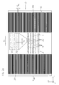
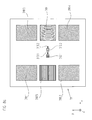
- the reference mark 31 is particularly on the FIG. 2a which shows a plan view of the reflection measuring graduation 30 in the region of the reference position x REF .
- the reference marking 31 has, in the region of the reference position x REF between the two incremental divisions 33.1, 33.2, a first set of structural elements 31.1 and a second set of structural elements 31.2 in specific geometrical arrangements.
- the structural elements 31.1, 31.2 of both sets are arranged in the plane of the reflection measuring graduation 30 perpendicular to the measuring direction x, ie in the indicated line direction y, periodically with a first transverse periodicity T1 or a second transverse periodicity T2.
- the reference marking 31 comprises a total of four separate sets of first structural elements 31.1 and four separate sets of second structural elements 31.2, which are arranged adjacent to each other in the measuring direction x. Accordingly, a total of eight sets of structural elements 31.1, 31.2 are arranged in measuring direction x.
- the arrangement of the four sets of first and second structural elements 31.1, 31.2 takes place in the measuring direction x mirror-symmetrical to a symmetry axis S, which is oriented perpendicular to the measuring direction x in the plane of the reflection measuring graduation 30.
- the symmetry axis S is in the present example exactly at the reference position x REF .
- Structural elements 31.1, 31.2 different Transverse periodicity T1, T2 are mirror-symmetric with respect to the symmetry axis S.
- the individual structural elements 31.1, 31.2 in this example each have a cross-sectional shape, which is composed of two in the transverse direction of extension y parallel boundary line and two curved in the longitudinal direction x, parallel boundary lines.
- the selected cross-sectional shape results in the optical effect of these elements explained in detail later.
- Sets with first and second structural elements 31.1, 31.2 differ iw by the different transverse periodicity T1, T2, with which the individual structural elements 31.1, 31.2 are arranged periodically in the direction y.
- the partial beams are due to the different transversal periodicities T1 and T2 in the various Sets also deflected differently in the y direction in the yz plane.
- the respective deflection angle depends here in a known manner directly with the respective transversal periodicity T1, T2.
- the back-reflected partial beams from the region of the reference mark 31 are imaged in the diaphragm plane.
- the two diaphragm structures 13.1, 13.2 arranged there are matched to the geometric arrangement of the sets of first and second structural elements 31.1, 31.2 of the reference marking 31 with respect to the geometric arrangement of the respective plurality of diaphragm openings. That is, the openings of a first diaphragm structure 13.1 are matched to the arrangement of the sets of first structural elements 31.1 and the openings of a second diaphragm structure 13.2 are matched to the arrangement of the sets of second structural elements 31.2. This is from the comparison of FIGS. 2a and 3b seen.
- FIGS. 2a and 3b see.
- the two reference pulse detector elements 15.1, 15.2 arranged downstream of the diaphragm structures 13.1, 13.2 can each detect a signal maximum of the signals S1, S2 detected above them.
- the imaging optics can alternatively also be formed as a lens array, which comprises a plurality of individual lenses.
- a lens array which comprises a plurality of individual lenses.
- longer sets with structural elements can be imaged in the diaphragm plane in line direction y.
- This has advantages in terms of the signal strength of the detected signals.
- a partial sequence of a set of structural elements is imaged by a single lens.
- each aperture of structural elements 31.1, 31.2 is associated with an aperture of the aperture structure 13.1, 13.2 in a defined manner.
- the positions of the apertures in turn result in a coordinated manner from the mapping of the sets of structural elements 31.1, 31.2 via the imaging optics 12 with the magnification m.
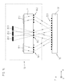
- Fig. 2b is again a plan view of the reflection measuring graduation 30 of the first position measuring device according to the invention in the region of the reference position x REF shown.
- the two incremental signal scanning fields 53.1, 53.2 are shown in the two incremental divisions 33.1, 33.2, which are each acted upon once by a scanning beam for generating the incremental signals INC A , INC B.
- the reference pulse scanning field 51 is in the range the reference mark in Fig. 2b recognizable, which is applied to the generation of the reference pulse signal RI by a scanning beam by means of the first scanning means once.
- the centers of the two incremental signal scanning fields 53.1, 53.2 and the reference pulse scanning field 51 lie on a straight line Gy in the scale graduation plane, which is oriented perpendicular to the measuring direction x.
- the position of the various scanning fields 51, 53.1, 53.2 on the reflection measuring graduation 30 is suitably adjusted by the corresponding design of the first and second scanning means.
- the desired insensitivity of the system can be achieved in the case of a possible moiré rotation of measuring standard 30 and scanning unit 10.
- the first and second scanning means are designed in such a way that the centers of the two incremental signal scanning fields 53.1 ', 53.2' lie on the reflection measuring graduation 30 'again on a straight line Gy' in the scale graduation plane which is oriented perpendicular to the measuring direction x.
- the center of the reference pulse signal scanning field 51 ' is arranged offset in the measuring direction x for this purpose.
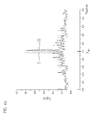
- the signals S1, S2 applied to the reference pulse detector elements 15.1, 15.2 in the region around the reference position x REF are in FIG. 4a shown. As from these signals S1, S2 ultimately the reference pulse signal of interest RI is generated, will be explained in detail in the course of the following description.
- FIGS. 2 In order to generate the incremental signals INC A , INC B by means of the second sampling means, particular reference should now be made to FIGS FIG. 2 as well as the FIGS. 1 a and 1b referenced, in which the sub-scanning beam paths for the incremental signal generation are respectively indicated by dashed lines.
- the beams emitted by the light source 14 for the incremental signal generation after the undeflected passing of the splitting grating 19 on the incremental graduation 33.2 on the Reflexionionsverêt 32 From there, a back reflection of split in the xz plane partial beams in the direction of the scanning unit 10, where the on the underside of the scanning 11 are arranged scanning gratings 18.3, 18.4 ( Fig. 1a ). These deflect the partial beams in the y-direction, so that the partial beams impinge on two reflector elements 17.1, 17.2 on the upper side of the scanning plate 11 ( Fig.
- the above-mentioned second scanning means for generating the incremental signals INC A , INC B in turn here include various optical elements in the scanning unit 10 or the scanning unit 10 associated elements, including at least a plurality of scanning grids 18.1 - 18.4, at least one integration grid 18.5 and at least two reflector elements 17.1 , 17.2. Furthermore, the incremental signal detector elements 20.1, 20.2, 20.3 are to be counted to the second scanning means.
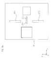
- FIGS. 3a and 3b The arrangement of the various optical elements for the generation of the reference pulse signal RI and the incremental signals INC A , INC B on the top and bottom of the scanning 11 is in the FIGS. 3a and 3b shown.
- the signals S1, S2 are generated in the region of the reference position x REF via the reference pulse detector elements 15.1, 15.2, as they are in Fig. 4a are shown.
- the width of the signals S1, S2 with approximately 15 ⁇ m is not sufficiently narrow enough for a reference pulse signal RI, in particular if high-resolution incremental signals INC A , INC B with signal periods of, for example, 0.5 ⁇ m are used as described above.
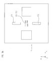
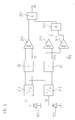
- FIG. 5 illustrated circuitry further processing of the signals S1, S2 provided in the present embodiment, which will be explained below.
- the signals S1, S2 at the reference pulse detector elements 15.1, 15.2 are in this case first supplied to current-voltage converters 21.1, 21.2.
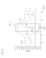
- a sum signal S1 + S2 and a difference signal S1-S2 are subsequently formed; the associated sum and difference signals S1 + S2, S1-S2 are in the range of the reference position x REF in Fig. 4b shown.
- the sum signal S1 + S2 is then fed to a first comparator element 24.1, at whose other input the reference signal or the trigger threshold TR1 is present.
- the difference signal S1-S2 is fed to a second and third comparator element 24.2, 24.3, at whose other inputs the trigger thresholds TR3 and TR2 are present as reference signals.
- FIG. 4b shows the position of the various trigger thresholds TR1, TR2 and TR3 in relation to the sum and difference signal S1 + S2, S1-S2.
- the output signal of the first comparator element 24.1 is then fed to a first input of an AND gate element 25.1. Its second input is supplied with the output signal of a second AND logic element 25.2, the latter having the output signals of the second and third comparator elements 24.2, 24.3 supplied.
- the position of the neutral pivot point can be adapted to the position of the neutral pivot point in the incremental signal generation when the reference pulse signal RI is generated. This represents an important measure for avoiding incorrect measurements in the event of a possible tilting of scanning unit 10 and reflection measuring graduation 30.
- the structural elements 31.1, 31.2 of the reference mark 31 are diffractive optical elements or diffractive structural elements which act optically in the measuring direction x as a cylindrical lens with a specific focal length f and consequently in the measuring direction x a virtual or real Focus in the Own the distance of the focal length f from the reflection scale.
- the structural elements 31.1, 31.2 have an optical effect such that they function as gratings with the transversal period T1 or T2.
- the selected focal length f of the structural elements 31.1, 31.2 preferably corresponds to half the distance of the neutral pivot point of the incremental signal scanning from the reflection measuring graduation 30, if this is due to the system above or below the reflection measuring graduation 30. In this way, the position of the neutral fulcrum of the reference pulse signal generation can be adjusted to the position of the neutral fulcrum of the incremental signal generation. It can thus be avoided in a possible tilting of the scanning unit 10 and reflection measuring graduation 30 otherwise resulting errors in the position measurement.
- the phase function describes the geometry of the imaging optics 12 in the form of the contour lines of this element.
- the focal length f of the structural elements 31.1, 31.2 of the reference marking 31 is selected equal to half the distance of the neutral pivot point N from the reflection measuring graduation 30 and the imaging optics 12 are matched to the position of the focal plane.
- FIG. 6b shows schematically that case in which the neutral pivot point N is due to scanning significantly above the material level.
- the focal length f of the structural elements 31.1, 31.2 of the reference marking 31 is also selected to be equal to half the distance of the neutral pivot point N from the reflection measuring graduation 30 and, in turn, matched to the position of the focal plane of the imaging optics 12.
- the neutral pivot point of the reference pulse signal generation can be brought into coincidence with the neutral pivot point of the incremental signal generation via the explained embodiment of the reference mark. Both signals are then influenced equally due to the measures according to the invention of a possible tilting of the reflection measuring graduation with respect to the scanning unit.
- the neutral pivot point of the incremental signal generation it is also possible for the neutral pivot point of the incremental signal generation to come to lie relatively close to the material scale.
- the mixed arrangement of the sets with the above-defined structural elements with defined optical effect on the one hand and the sets of structural elements without such an optical effect on the other hand makes it possible to move the neutral pivot point of the reference pulse signal generation in the immediate vicinity of the scale.
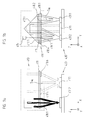
- FIGS. 7a . 7b 8a and 8b Based on FIGS. 7a . 7b 8a and 8b, a variant of the first position-measuring device according to the invention is explained below, which differs slightly from the example described above.
- the Fig. 7a and 7b again show partial scanning beam paths of this variant of the first position measuring device according to the invention, in the FIGS. 8a and 8b are views of the bottom and top of the scanning shown. In the following, only the components or the function of the same, which differ from the above example, will be explained.
- the solid partial scanning beam paths represent those beam paths which serve to generate the reference pulse signals
- the partial scanning beam paths shown by dashed lines represent the optical paths for incremental signal generation.
- convergent illumination of the reference mark 331 on the reflection measuring graduation 330 is provided. It has been found that convergent illumination of the reference mark 331 offers advantages such that the position of the neutral rotation point of the reference pulse signal generation is then largely independent of the scanning distance between the reflection measuring standard 330 and the scanning unit 310. In FIG. 7b the convergent illumination beam path between the splitting grating 319 and the reference marking 331 is indicated. The independence of the position of the neutral pivot point of the incremental signal generation from the sampling distance is also ensured by the selected sampling of the incremental divisions 333.1, 333.2.
- the splitting grating 319 is formed in the scanning unit 310 as an imaging lens in the form of a diffractive beam splitter element with curved grating lines, as in the underside view of the scanning plate 311 in Fig. 8a is indicated.
- the formation of the splitting grating 319 as imaging lens has in this variant of the first position measuring device according to the invention further modification in the scanning beam result.
- the split grating 319 and the aperture structures 313.1, 313.2 on the scanning plate 311 be precisely aligned with each other so that the resulting reference pulse signals remain positionally unchanged even if the scanning pitch changes.
- the diaphragm structures 313.1, 313.2 and the splitting grating 319 are arranged on the same side of the scanning plate 311 in contrast to the above example.
- Fig. 8a shows the underside of the scanning 311, where in the y-direction adjacent to the components of the imaging optics 312.1, 312.2 each aperture structures 313.1, 313.2 are arranged.
- reflector elements 321.1, 321.2 are also arranged on the upper side of the scanning plate 311 in the scanning beam path, as is shown in FIG. 8b is shown.
- this has the consequence that - as in Fig. 7b visible - from the reference mark 331 in the direction of scanning unit 310 reflected partial beams initially from the - in this example bipartite - imaging optics 312.1, 312.2 on the additional reflector elements 321.1, 321.2 in the plane of the diaphragm structures 313.1, 313.2 on the bottom of the scanning 311 mapped.
- the reflector elements 321.1, 321.2 are the reflector elements 321.1, 321.2 recognizable.
- the back-reflection in the direction of the detector elements 315.1, 315.2 for reference pulse signal generation is then effected by the diaphragm structures 313.1, 313.2 on the underside of the scanning plate 311. Due to this beam path, the diaphragm structures 313.1, 313.2 in this variant are, of course, not designed as structures which are transparent to light / opaque, but rather as reflective / non-reflective structures.
- the generation of the reference pulse and incremental signals functions as in the previously explained example.
- Fig. 9a, 9b . 10 and 11 a second position measuring device is explained.
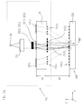
- the Fig. 9a and 9b show in a highly schematic form again partial scanning beam paths for generating the incremental signals and the reference pulse signal in the second position measuring device in different views.
- the partial scanning beam paths for reference pulse signal generation are shown in solid lines, whereas the partial scanning beam paths for generating the incremental signals are each dashed.
- the second position-measuring device in turn comprises a scanning unit 410, which is arranged to be movable relative to a material measure, embodied as a reflection measuring standard 430, at least in the measuring direction x.
- the reflection measuring standard 430 now has two reference-marking tracks extending parallel to the measuring direction x each have a reference mark 431.1, 431.2 at at least one reference position x REF .
- the reference marks 431.1, 431.2 are symmetrical with respect to Fig. 10 recognizable symmetry axis S x formed, which extends along the measuring direction x. Between the reference mark tracks, an incremental pitch track is arranged with a periodic incremental pitch 433.
- the sampling unit 410 comprises first sampling means for generating a reference pulse signal RI at the reference position x REF .
- the first scanning means or the corresponding scanning beam path ensures that the reference marks 431.1, 431.2 in the reference marking tracks of the scanning beam are each acted upon at least once in a reference pulse scanning field 451.1, 451.2 to generate the reference pulse signal RI.
- the corresponding reference pulse scanning fields 451.1, 451.2 are shown in the reference marking tracks.
- second scanning means are provided on the side of the scanning unit 410, which are used to generate the periodic incremental signals INC A , INC B.
- the second scanning means ensure by a corresponding scanning beam that for generating the incremental signals INC A , INC B the incremental graduation 433 in two incremental signal scanning 453.1, 453.2 is applied at least once, as is also in FIG. 10 is apparent.
- the reference marks 431.1, 431.2 arranged on both sides adjacent to the incremental graduation 433 are each in the form of cylindrical lenses which, as already mentioned above, are mirror-symmetrical to an axis of symmetry S x .
- the axis of symmetry S x extends parallel to the measuring direction x in the scale graduation plane.
- the reference markings 431.1, 431.2 are also formed mirror-symmetrically with respect to a further axis of symmetry Sy, which extends perpendicular to the measuring direction x in the scale graduation plane.
- the collimated beam S RI emitted by a light source first reaches the first reference mark 431.2 on the reflection measuring standard 430. There, a diffraction of the incident beam and a splitting into reflected +/- 1 diffraction orders occur Propagate direction scanning unit 410.
- the reference mark 431.1 designed as a cylindrical lens has a transverse periodicity T RI1 .
- the diverging partial beams reflected back to the scanning unit 410 pass in the scanning unit 410 respectively to diffractive scanning gratings 418.1, 418.2, which are arranged on the underside of a scanning plate 411.
- the scanning gratings 418.1, 418.2 again collimate the incident partial beams and redirect them with respect to the scanning plate plane such that the optical axes of the partial beams are oriented perpendicular to the scanning plate plane after passing through the scanning plate 411.
- the partial beams arrive at mirrored surfaces of a subordinate roof prism, which act as reflector elements 413.1, 413.2 and deflect the partial beams in the direction of two further diffractive Abtastgitter 418.3, 418.4, which are also arranged on the underside of the scanning 411.
- the two partial beams are again deflected in such a way that they propagate convergently in the direction of the second reference marking 431.2 on the material measure 430.
- the partial beams are interfering and are reflected back therefrom in the direction of the scanning unit 410, where they respond to a plurality of reference pulse detector elements of which in the figure, only the reference pulse detector element 415 can be seen.
- a reference pulse signal RI results at the reference pulse detector elements 415.
- various optical elements in the scanning unit 410 or the scanning unit 410 are assigned to elements associated with this position measuring device.
- the scanning gratings 418.1-418.4 and the reflector elements 413.1, 413.2 and the reference pulse signal detector elements 415 should be counted.
- the generation of the incremental signals INC A , INC B on the basis of the FIGS. 9a, 9b . 10 and 11 explained, which are generated in the second position measuring device by means of the second scanning means.
- the corresponding scanning beam is in the FIGS. 9a, 9b shown in dashed lines.
- the collimated beam S INC emitted by a light source arrives in a first incremental signal scanning field 453.1 for the first time on the incremental graduation 453 of the reflection measuring graduation 430.
- a single common light source is used supplying light to the first and second scanning means for scanning the incremental pitch 433 and the reference marks 431.1, 431.2; In principle, of course, the use of two separate light sources would be possible.
- the first incremental signal scanning field 453.1 a diffraction of the incident beam and a splitting into reflected +/- 1st diffraction orders propagating in the direction of the scanning unit 410 takes place.
- the incremental signal detector elements result in the case of the relative movement of material measure and sampling unit 410 periodic, phase-shifted incremental signals, which can then be converted in a known manner in a pair of incremental signals INC A , INC B with 90 ° phase offset.
- different optical elements in the scanning unit 410 or the scanning unit 410 thus again function in the second position-measuring device. These include the scanning gratings 418.5-418.8 and the reflector elements 413.1, 413.2 as well as the incremental signal detector elements.
- the centrally arranged incremental graduation 433 is acted upon once by the beam bundles used for scanning in the two incremental signal scanning fields 453.1, 453.2.
- the centers of the two incremental signal scanning fields 453.1, 453.2 lie on a first straight line G y1 , which extends perpendicular to the measuring direction x in the scale graduation plane;
- the centers of the two reference pulse signal scanning fields 451.1, 451.2 lie on a second straight line G y2 , which also extends perpendicular to the measuring direction x in the scale graduation plane and in the illustrated embodiment coincides with the already mentioned symmetry line S y .
- the two straight lines G y1 and G y2 are arranged offset to one another in the measuring direction x. Due to this staggered arrangement of the scanning fields, the above-mentioned suppression of signal crosstalk on the incremental track and a compact design result.
Description
Die vorliegende Erfindung betrifft eine Positionsmesseinrichtung.The present invention relates to a position measuring device.
Bekannte Positionsmesseinrichtungen liefern neben periodischen Inkrementalsignalen bzgl. des Relativversatzes zweier zueinander beweglicher Objekte auch sogenannte Referenzimpulssignale. Über die Referenzimpulssignale kann an bestimmten vorgegebenen Referenzpositionen entlang der Messstrecke ein exakter Absolutbezug bzgl. der Position der beiden zueinander beweglichen Objekte hergestellt werden. Auf die derart bestimmte Absolutposition kann dann die üblicherweise deutlich höher auflösende Inkrementalmessung nachfolgend bezogen werden.Known position-measuring devices deliver not only periodic incremental signals with respect to the relative offset of two mutually movable objects but also so-called reference pulse signals. By means of the reference pulse signals, an exact absolute reference with respect to the position of the two mutually movable objects can be established at certain predetermined reference positions along the measuring path. The usually significantly higher resolution incremental measurement can then be referred to the absolute position determined in this way.
Zur Erzeugung von Referenzimpulssignalen sind nunmehr bereits mehrere Anordnungsmöglichkeiten für Referenzmarkierungen auf der von der Abtasteinheit abgetasteten Maßverkörperung bekannt geworden.For generating reference pulse signals, several arrangement possibilities for reference markings on the material measure scanned by the scanning unit have already become known.
So sieht eine übliche Anordnungsvariante vor, ein oder mehrere Referenzmarkierungen seitlich benachbart zur abgetasteten Inkrementalteilungsspur anzuordnen; hierzu sei etwa auf die
Es wurden daher, wie z.B. in der
Aus der
Aufgabe der vorliegenden Erfindung ist es, eine Positionsmesseinrichtung anzugeben, die zur Erzeugung von hochauflösenden Inkrementalsignalen wie auch zur Erzeugung von Referenzimpulssignalen an mindestens einer Referenzposition geeignet ist und die möglichst gering durch eventuelle Moire-Verdrehungen von Maßverkörperung und Abtasteinheit beeinflusst wird.The object of the present invention is to provide a position measuring device which is suitable for generating high-resolution incremental signals as well as for generating reference pulse signals at at least one reference position and which is as small as possible by possible Moire distortions of material measure and scanning unit is affected.
Diese Aufgabe wird durch eine erste Positionsmesseinrichtung mit den Merkmalen des Anspruchs 1 gelöst.This object is achieved by a first position-measuring device with the features of
Vorteilhafte Ausführungsformen der ersten Positionsmesseinrichtung ergeben sich aus den Maßnahmen, die in den von Anspruch 1 abhängigen Ansprüchen aufgeführt sind.Advantageous embodiments of the first position-measuring device result from the measures that are listed in the dependent of
Eine erste erfindungsgemäße Positionsmesseinrichtung zur Erzeugung von Inkrementalsignalen und einem Referenzimpulssignal an mindestens einer Referenzposition umfasst nunmehr eine Abtasteinheit sowie eine hierzu in mindestens einer Messrichtung bewegliche Maßverkörperung. Die Maßverkörperung umfasst zwei sich parallel in Messrichtung erstreckende Inkrementalteilungsspuren mit periodischen Inkrementalteilungen zwischen denen eine Referenzmarkierungsspur angeordnet ist, die an mindestens einer Referenzposition eine Referenzmarkierung aufweist. Die Abtasteinheit umfasst erste Abtastmittel zur Erzeugung des Referenzimpulssignals und zweite Abtastmittel zur Erzeugung der Inkrementalsignale, wobei zur Erzeugung der Inkrementalsignale jede der Inkrementalteilungen von einem Abtast-Strahlenbündel mindestens einmal in einem Inkrementalsignal-Abtastfeld beaufschlagt wird.A first position-measuring device according to the invention for generating incremental signals and a reference-pulse signal at at least one reference position now comprises a scanning unit and a measuring standard movable in at least one measuring direction. The measuring graduation comprises two incremental graduation tracks extending in the measuring direction with periodic incremental divisions between which a reference marking track is arranged, which has a reference marking at at least one reference position. The scanning unit comprises first scanning means for generating the reference pulse signal and second scanning means for generating the incremental signals, wherein for generating the incremental signals each of the incremental divisions of a scanning beam is applied at least once in an incremental signal scanning field.
Die erfindungsgemäße Ausgestaltung der ersten Positionsmesseinrichtung gewährleistet nunmehr, dass auch bei einer eventuellen Moire-Verdrehung von Maßverkörperung und Abtasteinheit keine Fehler bei der Positionsbestimmung resultieren. Es ist stets eine korrekte Zuordnung des erzeugten Referenzimpulssignales zur gewünschten Inkrementalsignalperiode sichergestellt, da die Inkrementalteilungsspuren und die Referenzmarkierungsspur die gleiche sog. neutrale Moiré-Achse besitzen, um die eine eventuelle Verdrehung von Maßverkörperung und Abtasteinheit keine Fehlmessung verursacht.The inventive design of the first position measuring device now ensures that even with a possible moire twisting of material measure and scanning unit no errors in the position determination result. The correct assignment of the generated reference pulse signal to the desired incremental signal period is always ensured since the incremental graduation tracks and the reference marking track have the same so-called neutral moiré axis, around which a possible rotation of the measuring scale and the scanning unit does not cause any erroneous measurement.
Als weiterer Vorteil der erfindungsgemäßen Lösung ist anzuführen, dass auch im Fall starker Moiré-Verdrehungen von Maßverkörperung und Abtasteinheit relativ stabile Inkrementalsignal-Amplituden resultieren. Dies ist insbesondere bei der Weiterverarbeitung der Inkrementalsignale, z.B. einer eventuellen Interpolation derselben, von Bedeutung.A further advantage of the solution according to the invention is that relatively strong incremental signal amplitudes result even in the case of strong moire distortions of the material measure and the scanning unit. This is especially true in the further processing of the incremental signals, e.g. a possible interpolation of the same, of importance.
Vorzugsweise weist die erste erfindungsgemäße Positionsmesseinrichtung eine Referenzmarkierung mit mehreren Strukturelementen aufweist, die spiegelsymmetrisch zu einer Symmetrieachse angeordnet sind, die senkrecht zur Messrichtung in der Maßverkörperungsebene orientiert ist.Preferably, the first position measuring device according to the invention has a reference marking with a plurality of structural elements which are arranged mirror-symmetrically to an axis of symmetry which is oriented perpendicular to the measuring direction in the scale graduation plane.
Die Strukturelemente der Referenzmarkierung sind mit Vorteil spiegelsymmetrisch zu einer Symmetrieachse (Sx) angeordnet, die sich parallel zur Messrichtung (x) in der Maßverkörperungsebene erstreckt.The structural elements of the reference marking are advantageously arranged mirror-symmetrically to an axis of symmetry (Sx) which extends parallel to the measuring direction (x) in the scale graduation plane.
Über die ersten Abtastmittel in der Abtasteinheit zur Erzeugung des Referenzimpulssignals wird die Referenzmarkierung auf der Maßverkörperung vorzugsweise einmal in einem Referenzimpuls-Abtastfeld beaufschlagt.By way of the first scanning means in the scanning unit for generating the reference pulse signal, the reference marking on the material measure is preferably applied once in a reference pulse scanning field.
Hierbei liegen die Zentren der beiden Inkrementalsignal-Abtastfelder und das Zentrum des Referenzimpuls-Abtastfelds beispielsweise auf einer Geraden in der Maßverkörperungsebene, die senkrecht zur Messrichtung orientiert ist.In this case, the centers of the two incremental signal scanning fields and the center of the reference pulse scanning field lie, for example, on a straight line in the scale graduation plane which is oriented perpendicular to the measuring direction.
Alternativ hierzu liegen wobei die Zentren der beiden Inkrementalsignal-Abtastfelder auf einer Geraden in der Maßverkörperungsebene, die senkrecht zur Messrichtung orientiert ist und das Zentrum des Referenzimpuls-Abtastfelds ist in Messrichtung versetzt zu dieser Geraden auf der Maßverkörperung angeordnet.Alternatively, the centers of the two incremental signal scanning fields lie on a straight line in the scale graduation plane which is oriented perpendicular to the measuring direction and the center of the reference pulse scanning field is arranged offset in the direction of measurement to this line on the measuring scale.
Vorzugsweise weist die Referenzmarkierung an der Referenzposition
- mindestens einen Satz erster Strukturelemente auf, die in der Ebene der Maßverkörperung senkrecht zur Messrichtung periodisch mit einer ersten Transversalperiodizität angeordnet sind und
- weist mindestens einen Satz zweiter Strukturelemente auf, die in der Ebene der Maßverkörperung senkrecht zur Messrichtung periodisch mit einer zweiten Transversalperiodizität angeordnet sind, wobei sich die erste und die zweite Transversalperiodizität voneinander unterscheiden und
- es sind die Strukturelemente als diffraktive Strukturelemente ausgebildet, die in der Messrichtung optisch wie eine Zylinderlinse mit einer bestimmten Brennweite wirken und senkrecht zur Messrichtung wie ein Ablenkgitter mit der ersten oder zweiten Transversalperiodizität wirken und
- die Strukturelemente besitzen in Messrichtung einen virtuellen oder reellen Brennpunkt im Brennweiten-Abstand f von der Reflexions-Maßverkörperung.
- at least one set of first structural elements, which are arranged in the plane of the material measure perpendicular to the measuring direction periodically with a first transversal periodicity, and
- has at least one set of second structural elements, which are arranged in the plane of the measuring standard perpendicular to the measuring direction periodically with a second transversal periodicity, wherein the first and second transversal periodicity differ from one another and
- the structural elements are designed as diffractive structural elements which act in the measuring direction optically like a cylindrical lens with a specific focal length and act perpendicular to the measuring direction like a deflection grating with the first or second transverse periodicity and
- the structural elements have a virtual or real focus in the measuring direction in the focal distance f of the reflection measuring graduation.
Mit Vorteil umfassen die ersten Abtastmittel in der Abtasteinheit zur Erzeugung des Referenzimpulssignals
- mehrere optische Elemente, worunter mindestens eine Abbildungsoptik, sowie mindestens zwei in einer Blendenebene angeordnete Blendenstrukturen mit jeweils mehreren Blendenöffnungen sind sowie
- mindestens zwei Referenzimpuls-Detektorelemente.
- a plurality of optical elements, among which at least one imaging optics, as well as at least two diaphragm structures arranged in a diaphragm plane, each having a plurality of diaphragm openings, and
- at least two reference pulse detector elements.
Hierbei ist die Abbildungsoptik in der Abtasteinheit derart dimensioniert, dass darüber eine Abbildung der bildseitigen Brennebene der Strukturelemente in die Blendenebene resultiert, wobei die positionsmäßige Anordnung der Blendenöffnungen der beiden Blendenstrukturen in Messrichtung auf die Anordnung der Strukturelemente der Referenzmarkierung abgestimmt ist.In this case, the imaging optics in the scanning unit is dimensioned such that an image of the image-side focal plane of the structural elements results in the diaphragm plane, whereby the positional arrangement of the diaphragm apertures of the two diaphragm structures in the measuring direction is matched to the arrangement of the structural elements of the reference marker.
Mit Vorteil umfasst die Abtasteinheit ferner eine Abtastplatte, auf der die Blendenstrukturen und die Abbildungsoptik angeordnet sind.Advantageously, the scanning unit further comprises a scanning plate on which the diaphragm structures and the imaging optics are arranged.
Beispielsweise umfassen ferner die zweiten Abtastmittel in der Abtasteinheit zur Erzeugung der Inkrementalsignale
- mehrere optische Elemente, worunter mehrere Abtastgitter, mindestens ein Vereinigungsgitter sowie mindestens zwei Reflektorelemente sind, über die eine Rückreflexion der aus einem ersten Inkrementalsignal-Abtastfeld kommenden Strahlenbündel in ein zweites Inkrementalsignal-Abtastfeld erfolgt und
- mehrere Inkrementalsignal-Detektorelemente .
- a plurality of optical elements, among which a plurality of scanning gratings, at least one combining grating and at least two reflector elements, via which a return reflection of the radiation beam coming from a first incremental signal scanning field into a second incremental signal scanning field takes place, and
- a plurality of incremental signal detector elements.
Hierbei umfasst die die Abtasteinheit eine Abtastplatte, auf der die Abtastgitter, das Vereinigungsgitter sowie die Reflektorelemente angeordnet sind.In this case, the scanning unit comprises a scanning plate, on which the scanning gratings, the joining gratings and the reflector elements are arranged.
Vorzugsweise ist der Abtasteinheit ferner eine Lichtquelle zugeordnet, die die ersten und zweiten Abtastmittel mit Licht zur Abtastung der Inkrementalteilungen und der Referenzmarkierung versorgt und die Abtasteinheit umfasst ferner ein Aufspaltgitter, welches das von der Lichtquelle kommende Strahlenbündel in ein erstes Teilstrahlenbündel für die ersten Abtastmittel zur Referenzimpulssignalerzeugung und ein zweites Teilstrahlenbündel für die zweiten Abtastmittel zur Inkrementalsignalerzeugung aufspaltet.Preferably, the scanning unit is further associated with a light source which supplies the first and second scanning means with light for scanning the incremental graduations and the reference mark, and the scanning unit further comprises a splitting grid which converts the beam from the light source into a first sub-beam for the first reference pulse signal generating means and split a second sub-beam for the second scanning means for incremental signal generation.
Hierbei ist das Aufspaltgitter derart ausgebildet, dass eine konvergente Beleuchtung der Referenzmarkierung auf der Reflexions-Maßverkörperung resultiert.In this case, the splitting grid is designed such that a convergent illumination of the reference marking on the reflection measuring graduation results.
Das Aufspaltgitter kann auf der Seite der Abtastplatte angeordnet sein, die der Maßverkörperung zugewandt ist.The splitting grid can be arranged on the side of the scanning plate, which faces the material measure.
Eine zweite Positionsmesseinrichtung zur Erzeugung von Inkrementalsignalen und einem Referenzimpulssignal an mindestens einer Referenzposition umfasst nunmehr eine Abtasteinheit sowie eine hierzu in mindestens einer Messrichtung bewegliche Maßverkörperung. Die Maßverkörperung umfasst zwei sich parallel in Messrichtung erstreckende Referenzmarkierungsspuren, die jeweils an mindestens einer Referenzposition eine Referenzmarkierung aufweisen, die symmetrisch bzgl. einer Symmetrieachse in Messrichtung ausgebildet sind. Zwischen den Referenzmarkierungsspuren ist eine Inkrementalteilungsspur mit einer periodischen Inkrementalteilung angeordnet. Die Abtasteinheit umfasst erste Abtastmittel zur Erzeugung des Referenzimpulssignals, wobei zur Erzeugung des Referenzimpulssignals die Referenzmarkierungen in den Referenzmarkierungsspuren von einem Abtast-Strahlenbündel jeweils mindestens einmal in einem Referenzimpulssignal-Abtastfeld beaufschlagt werden. Ferner sind zweite Abtastmittel in der Abtasteinheit zur Erzeugung der Inkrementalsignale vorgesehen, wobei zur Erzeugung der Inkrementalsignale die Inkrementalteilung von einem Abtast-Strahlenbündel in zwei Inkrementalsignal-Abtastfeldern jeweils mindestens einmal beaufschlagt wird.A second position-measuring device for generating incremental signals and a reference-pulse signal at at least one reference position now comprises a scanning unit and a measuring graduation movable in at least one measuring direction for this purpose. The material measure comprises two reference marking tracks extending parallel to one another in the measuring direction, each of which has a reference marking on at least one reference position which is symmetrical with respect to an axis of symmetry are formed in the measuring direction. Between the reference mark tracks is arranged an incremental pitch track with a periodic incremental pitch. The scanning unit comprises first scanning means for generating the reference pulse signal, wherein for generating the reference pulse signal, the reference marks in the reference marking tracks of a scanning beam are applied at least once each in a reference pulse signal scanning field. Furthermore, second scanning means are provided in the scanning unit for generating the incremental signals, wherein for generating the incremental signals, the incremental graduation from a scanning beam in two incremental signal scanning fields is applied at least once in each case.
Die Ausgestaltung der zweiten Positionsmesseinrichtung gewährleistet wie auch bereits die erste Positionsmesseinrichtung, dass damit ein Referenzimpulssignal mit einer Breite erzeugt werden kann, die der Breite der Inkrementalsignale entspricht. Damit ist eine höhere Zuverlässigkeit der Positionsmesseinrichtungen verbunden.The design of the second position-measuring device, like the first position-measuring device, ensures that a reference-pulse signal can be generated with a width that corresponds to the width of the incremental signals. This is associated with a higher reliability of the position measuring devices.
In der zweiten Positionsmesseinrichtung sind die Referenzmarkierungen vorzugsweise spiegelsymmetrisch zu einer Symmetrieachse ausgebildet, die senkrecht zur Messrichtung in der Maßverkörperungsebene orientiert ist.In the second position-measuring device, the reference markings are preferably mirror-symmetrical to an axis of symmetry which is oriented perpendicular to the measuring direction in the scale graduation plane.
Hierbei können die Zentren der beiden Inkrementalsignal-Abtastfelder auf einer ersten Geraden in der Maßverkörperungsebene liegen, die senkrecht zur Messrichtung orientiert ist und die Zentren der Referenzimpuls-Abtastfelder auf einer zweiten Geraden in der Maßverkörperungsebene, die senkrecht zur Messrichtung orientiert ist, wobei die beiden Geraden in Messrichtung versetzt zueinander auf der Maßverkörperung angeordnet sind.In this case, the centers of the two incremental signal scanning fields can lie on a first straight line in the measuring graduation plane oriented perpendicular to the measuring direction and the centers of the reference pulse scanning fields on a second straight line in the measuring graduation plane oriented perpendicular to the measuring direction, the two straight lines offset in the measuring direction to each other are arranged on the measuring scale.
Mit Vorteil sind in der zweiten Positionsmesseinrichtung die Referenzmarkierungen jeweils als Zylinderlinsen auf der Maßverkörperung ausgebildet, die eine Transversalperiodizität besitzen, so dass die beiden ersten Beugungsordnungen räumlich getrennt vom beleuchtenden Abtast-Strahlenbündel auf eine Abtastplatte in der Abtasteinheit treffen.Advantageously, in the second position-measuring device, the reference markings are each formed as cylindrical lenses on the material measure, which have a transversal periodicity, so that the two first diffraction orders spatially separated from the illuminating scanning beam on a scanning in the scanning meet.
In der zweiten Positionsmesseinrichtung umfassen die ersten Abtastmittel in der Abtasteinheit zur Erzeugung des Referenzimpulssignals vorzugsweise mehrere optische Elemente, worunter mehrere Abtastgitter und Reflektorelemente sind, über die eine Rückreflexion der aus einem ersten Referenzimpuls-Abtastfeld der ersten Referenzmarkierungsspur kommenden Strahlenbündel in ein zweites Referenzimpuls-Abtastfeld der zweiten Referenzmarkierungsspur erfolgt. Ferner umfassen die ersten Abtastmittel ein oder mehrere Referenzimpuls-Detektorelemente.In the second position measuring device, the first scanning means in the scanning unit for generating the reference pulse signal preferably comprise a plurality of optical elements, among which a plurality of scanning gratings and reflector elements, via which a return reflection of the coming of a first reference pulse scanning field of the first reference mark track beam into a second reference pulse scanning field second reference mark track. Furthermore, the first scanning means comprise one or more reference pulse detector elements.
Hierbei kann die Abtasteinheit eine Abtastplatte umfassen, auf deren der Maßverkörperung zugewandten Seite mehrere diffraktive Abtastgitter angeordnet sind und auf deren entgegengesetzter Seite ein retroreflektierendes Dachkantprisma angeordnet ist, das mehrere verspiegelte Flächen als Reflektorelemente aufweist.In this case, the scanning unit can comprise a scanning plate, on whose side facing the measuring graduation a plurality of diffractive scanning gratings are arranged and on the opposite side a retroreflective roof prism is arranged, which has a plurality of mirrored surfaces as reflector elements.
In der zweiten Positionsmesseinrichtung umfassen die zweiten Abtastmittel in der Abtasteinheit zur Erzeugung der Inkrementalsignale vorzugsweise mehrere optische Elemente, worunter mehrere Abtastgitter, ein optionales Vereinigungsgitter sowie mindestens zwei Reflektorelemente sind. Ferner umfassen die zweiten Abtastmittel mehrere Inkrementalsignal-Detektorelemente.In the second position measuring device, the second scanning means in the scanning unit for generating the incremental signals preferably comprise a plurality of optical elements, among which a plurality of scanning gratings, an optional joining grid and at least two reflector elements. Furthermore, the second scanning means comprise a plurality of incremental signal detector elements.
Hierbei erfolgt über die Reflektorelemente vorzugsweise eine Rückreflexion der aus einem ersten Inkrementalsignal-Abtastfeld kommenden Strahlenbündel in ein zweites Inkrementalsignal-Abtastfeld.In this case, a return reflection of the radiation beam coming from a first incremental signal scanning field preferably takes place via the reflector elements into a second incremental signal scanning field.
In der zweiten Positionsmesseinrichtung umfasst ferner vorzugsweise die Abtasteinheit eine Abtastplatte, auf deren der Maßverkörperung zugewandten Seite mehrere diffraktive Abtastgitter sowie ein optionales Vereinigungsgitter angeordnet sind und auf deren entgegengesetzter Seite ein retroreflektierendes Dachkantprisma angeordnet ist, das mehrere verspiegelte Flächen als Reflektorelemente aufweist.In the second position-measuring device, the scanning unit further preferably comprises a scanning plate, on the side of which the measuring scale side is facing, a plurality of diffractive scanning gratings and an optional joining grating are arranged and on the opposite Side a retroreflective roof prism is arranged, which has a plurality of mirrored surfaces as reflector elements.
Mit Vorteil ist hierbei der Abtasteinheit ferner eine Lichtquelle zugeordnet, die die ersten und zweiten Abtastmittel mit Licht zur Abtastung der Inkrementalteilung und der Referenzmarkierungen versorgt.Advantageously, the scanning unit is further associated with a light source which supplies the first and second scanning means with light for scanning the incremental pitch and the reference marks.
Weitere Einzelheiten und Vorteile der vorliegenden Erfindung seien anhand der nachfolgenden Beschreibung von Ausführungsbeispielen erfindungsgemäßer Positionsmesseinrichtungen in Verbindung mit den Figuren erläutert.Further details and advantages of the present invention will be explained with reference to the following description of exemplary embodiments of inventive position measuring devices in conjunction with the figures.
Es zeigt hierbei:
- Figur 1a
- eine erste Ansicht von Teil-Abtaststrahlengängen einer ersten erfindungsgemäßen Positionsmesseinrichtung zur Erläuterung der Referenzimpulssignalerzeugung;
- Figur 1b
- eine zweite Ansicht von Teil-Abtaststrahlengängen der ersten erfindungsgemäßen Positionsmesseinrichtung zur Erläuterung der Referenzimpulssignalerzeugung;
- Figur 1c
- eine dritte Ansicht von Teil-Abtaststrahlengängen der ersten erfindungsgemäßen Positionsmesseinrichtung zur Erläuterung der Inkrementalsignalerzeugung;
- Figur 2a
- eine Teil-Draufsicht auf die Reflexions-Maßverkörperung der ersten erfindungsgemäßen Positionsmesseinrichtung inclusive einer Ausschnittsvergrößerung der Referenzmarkierung;
- Figur 2b
- eine Teil-Draufsicht auf die Reflexions-Maßverkörperung der ersten erfindungsgemäßen Positionsmesseinrichtung inclusive den Abtastfeldern in der Referenzmarkierungsspur und in den Inkrementalteilungsspuren;
- Figur 2c
- eine Teil-Draufsicht auf die Reflexions-Maßverkörperung einer Abwandlung der ersten erfindungsgemäßen Positionsmesseinrichtung inclusive den Abtastfeldern in der Referenzmarkierungsspur und in den Inkrementalteilungsspuren;
- Figur 3a
- eine Draufsicht auf die Unterseite der Abtastplatte der ersten erfindungsgemäßen Positionsmesseinrichtung;
- Figur 3b
- eine Draufsicht auf die Oberseite der Abtastplatte der ersten erfindungsgemäßen Positionsmesseinrichtung;
- Figur 4a
- eine Darstellung der resultierenden Signale zur Referenzimpulserzeugung mit der ersten erfindungsgemäßen Positionsmesseinrichtung;
- Figur 4b
- eine Darstellung der Summen- und Differenzsignale, die aus den Signalen gemäß
Fig. 4a gebildet werden, inclusive der zur Referenzimpulssignal-Erzeugung genutzten Triggerschwellen; - Figur 4c
- eine Darstellung des resultierenden ReferenzimpulsSignals an der Referenzposition inclusive einer Darstellung der Inkrementalsignale;
- Figur 5
- eine schematisierte Darstellung einer geeigneten Schaltungsanordnung zur Verarbeitung der verschiedenen Signale und zur Erzeugung des Referenzimpulssignals gemäß den
Figuren 4a - 4c ; - Figur 6a - 6c
- verschiedene Darstellungen analog zu
Figur 1b mit unterschiedlichen Positionen des neutralen Drehpunkts bzw. mit verkippter Reflexions-Maßverkörperung; - Figur 7a
- eine erste Ansicht von Teil-Abtaststrahlengängen einer Variante der ersten erfindungsgemäßen Positionsmesseinrichtung zur Erläuterung der Referenzimpulssignalerzeugung;
- Figur 7b
- eine zweite Ansicht von Teil-Abtaststrahlengängen der Variante der ersten erfindungsgemäßen Positionsmesseinrichtung aus
Fig. 7a zur Erläuterung der Referenzimpulssignalerzeugung; - Figur 8a
- eine Draufsicht auf die Unterseite der Abtastplatte der Variante der ersten erfindungsgemäßen Positionsmesseinrichtung;
- Figur 8b
- eine Draufsicht auf die Oberseite der Abtastplatte der Variante der ersten der erfindungsgemäßen Positionsmesseinrichtung;
- Figur 9a
- eine erste Ansicht von Teil-Abtaststrahlengängen einer zweiten Positionsmesseinrichtung zur Erläuterung der Signalerzeugung;
- Figur 9b
- eine zweite Ansicht von Teil-Abtaststrahlengängen der zweiten Positionsmesseinrichtung zur Erläuterung der Signalerzeugung;
Figur 10- eine Teil-Draufsicht auf die Reflexions-Maßverkörperung der zweiten Positionsmesseinrichtung inclusive den Abtastfeldern in den Referenzmarkierungsspuren und in der Inkrementalteilungsspur;
Figur 11- eine Draufsicht auf die Unterseite der Abtastplatte der zweiten Positionsmesseinrichtung.
- FIG. 1a
- a first view of partial scanning beam paths of a first position measuring device according to the invention for explaining the reference pulse signal generation;
- FIG. 1b
- a second view of partial scanning beam paths of the first position measuring device according to the invention for explaining the reference pulse signal generation;
- Figure 1c
- a third view of partial scanning beam paths of the first position measuring device according to the invention for explaining the incremental signal generation;
- FIG. 2a
- a partial top view of the reflection measuring graduation of the first position measuring device according to the invention including an enlarged detail of the reference mark;
- FIG. 2b
- a partial top view of the reflection measuring graduation of the first position measuring device according to the invention including the scan fields in the reference mark track and in the incremental pitch tracks;
- Figure 2c
- a partial top view of the reflection measuring graduation of a modification of the first position measuring device according to the invention including the scanning fields in the reference mark track and in the incremental graduation tracks;
- FIG. 3a
- a plan view of the underside of the scanning of the first position measuring device according to the invention;
- FIG. 3b
- a plan view of the top of the scanning of the first position measuring device according to the invention;
- FIG. 4a
- a representation of the resulting signals for reference pulse generation with the first position measuring device according to the invention;
- FIG. 4b
- a representation of the sum and difference signals resulting from the signals according to
Fig. 4a are formed, including the trigger thresholds used for reference pulse signal generation; - Figure 4c
- a representation of the resulting reference pulse signal at the reference position including a representation of the incremental signals;
- FIG. 5
- a schematic representation of a suitable circuit arrangement for processing the various Signals and for generating the reference pulse signal in accordance with
FIGS. 4a-4c ; - Figure 6a - 6c
- different representations analogous to
FIG. 1b with different positions of the neutral pivot point or with tilted reflection measuring graduation; - Figure 7a
- a first view of partial scanning beam paths of a variant of the first position measuring device according to the invention for explaining the reference pulse signal generation;
- FIG. 7b
- a second view of partial scanning beam paths of the variant of the first position measuring device according to the invention
Fig. 7a to explain the reference pulse signal generation; - FIG. 8a
- a plan view of the underside of the scanning of the variant of the first position measuring device according to the invention;
- FIG. 8b
- a plan view of the top of the scanning of the variant of the first of the position measuring device according to the invention;
- FIG. 9a
- a first view of partial scanning beam paths of a second position measuring device for explaining the signal generation;
- FIG. 9b
- a second view of partial scanning beam paths of the second position measuring device for explaining the signal generation;
- FIG. 10
- a partial top view of the reflection measuring graduation of the second position measuring device including the scanning fields in the reference mark tracks and in the incremental graduation track;
- FIG. 11
- a plan view of the underside of the scanning of the second position measuring device.
Anhand der
Die
In den
Die dargestellte erste erfindungsgemäße optische Positionsmesseinrichtung umfasst eine Maßverkörperung, ausgebildet als Reflexions-Maßverkörperung 30 sowie eine hierzu in mindestens einer Messrichtung x bewegliche Abtasteinheit 10. Die Reflexions-Maßverkörperung 30 und die Abtasteinheit 10 sind mit zwei zueinander beweglichen Objekten verbunden, beispielsweise Maschinenteilen. Über die Positionsmesseinrichtung werden Positionssignale bzgl. der Lage der beiden zueinander beweglichen Objekte erzeugt und einer - nicht dargestellten - Steuereinheit zugeführt. Diese nutzt die Positionsdaten in bekannter Art und Weise zu Steuerungszwecken. Die erfindungsgemäße Positionsmesseinrichtung kann hierbei sowohl bzgl. linearer als auch bzgl. rotatorischer Verschiebebewegungen ausgebildet werden.The illustrated first optical position-measuring device according to the invention comprises a measuring graduation, designed as a
Das dargestellte erste erfindungsgemäße Positionsmesseinrichtung liefert - wie nachfolgend erläutert - neben periodischen Inkrementalsignalen INCA, INCB noch ein Referenzimpulssignal RI an mindestens einer bekannten Referenzposition xREF entlang der Messstrecke. Auf die derart bestimmte, bekannte Absolutposition kann dann die deutlich höher auflösende Inkrementalmessung nachfolgend in üblicher Art und Weise bezogen werden.The illustrated first position measuring device according to the invention provides - as explained below - in addition to periodic incremental signals INC A , INC B nor a reference pulse signal RI at least one known reference position x REF along the measuring path. On the thus determined, known absolute position then the significantly higher resolution incremental measurement can be subsequently obtained in a conventional manner.
Hierzu umfasst die Abtasteinheit 10 erste Abtastmittel zur Erzeugung des Referenzimpulssignals RI sowie zweite Abtastmittel zur Erzeugung der Inkrementalsignale INCA, INCB.For this purpose, the
Zunächst sei die Erzeugung des Referenzimpulssignals RI mittels der ersten Abtastmittel anhand der hierzu vorgesehenen Teil-Abtaststrahlengänge erläutert.First, the generation of the reference pulse signal RI is explained by means of the first scanning means based on the partial scanning beam paths provided for this purpose.
Die als Reflexions-Maßverkörperung 30 ausgebildete Maßverkörperung umfasst neben einer oder mehreren sich in Messrichtung x erstreckenden Inkrementalteilungsspuren mit periodischen Inkrementalteilungen 33.1, 33.2 ferner mindestens eine Referenzmarkierungsspur mit einer Referenzmarkierung 31 an einer definierten Referenzposition xREF. Grds. kann natürlich auch vorgesehen werden, mehrere Referenzmarkierungen an verschiedenen Referenzpositionen anzuordnen, beispielsweise in Form sog. abstandscodierter Referenzmarkierungen etc..The dimensional standard embodied as a
Wie aus der Draufsicht auf einen Teil der Reflexions-Maßverkörperung 30 in
Es sei an dieser Stelle darauf hingewiesen, dass die erste erfindungsgemäße Positionsmesseinrichtung natürlich auch mit einer als Durchlicht-Maßverkörperung ausgebildeten Maßverkörperung ausgebildet werden kann, die z.B. alternierend angeordnete Teilungsbereiche mit unterschiedlichen Transmissionseigenschaften aufweist.It should be noted at this point that the first position-measuring device according to the invention can, of course, also be formed with a material measure designed as a transmitted-light measuring standard, which can be e.g. having alternately arranged division regions with different transmission properties.
An der Referenzposition xREF ist zwischen den beiden Spuren für die Inkrementalteilungen 33.1, 33.2 eine Referenzmarkierung 31 in der Referenzmarkierungsspur angeordnet. Diese besteht wie die Inkrementalteilungen 33.1, 33.2 aus einer bestimmten Anordnung von Teilbereichen bzw. Strukturelementen 31.1, 31.2 mit unterschiedlichen Reflexionseigenschaften. Deren bevorzugte Ausgestaltung wird für das vorliegende Beispiel der ersten erfindungsgemäßen Positionsmesseinrichtung nachfolgend noch detailliert erläutert.At the reference position x REF , a
Auf Seiten der Abtasteinheit 10 sind im vorliegenden Beispiel eine Lichtquelle 14, z.B. eine Laserdiode, sowie eine Kollimationsoptik 16, mehrere Referenzimpuls-Detektorelemente 15.1, 15.2 für die ReferenzimpulssignalErzeugung, mehrere Inkrementalsignal-Detektorelemente 20.1, 20.2, 20.3 für die Inkrementalsignalerzeugung (
Zu den oben erwähnten ersten Abtastmitteln zur Erzeugung des Referenzimpulssignals RI gehören hierbei verschiedene optische Elemente in der Abtasteinheit 10 bzw. der Abtasteinheit zugeordnete Elemente, darunter mindestens die Abbildungsoptik 12 sowie die in der Blendenebene angeordneten Blendenstrukturen 13.1, 13.2 mit jeweils mehreren Blendenöffnungen. Ferner sind die Referenzimpuls-Detektorelemente 15.1, 15.2 zu den ersten Abtastmitteln zu zählen.The above-mentioned first scanning means for generating the reference pulse signal RI here include various optical elements in the
Es sei an dieser Stelle darauf hingewiesen, dass sich die Lichtquelle 14, die Kollimationsoptik 16 und die verschiedenen Detektorelemente 15.1, 15.2, 20.1, 20.2, 20.3 nicht unbedingt in der Abtasteinheit 10 bzw. in einem entsprechenden Gehäuse derselben befinden müssen. So wäre in alternativen Varianten der vorliegenden Erfindung grundsätzlich auch möglich, diese Komponenten in bekannter Art und Weise mittels Lichtwellenleitern der Abtasteinheit 10 zuzuordnen und die verschiedenen Elemente räumlich getrennt außerhalb der Abtasteinheit 10 zu platzieren.It should be noted at this point that the
Das nach der Kollimationsoptik 16 parallel-gerichtete Strahlenbündel wird von einem Aufspaltgitter 19 in einen Abtaststrahlengang (durchgezogene Berandungslinien in
Die Platzierung der Referenzmarkierung 31 zwischen den beiden Inkrementalteilungen 33.1, 33.2 bietet den maßgeblichen erfindungsgemäßen Vorteil, dass sich im Fall einer eventuellen Verdrehung von Reflexions-Maßverkörperung 30 und Abtasteinheit 10 um die z-Achse (Moire-Verdrehung) keine (verfälschende) Veränderung der Lage des Referenzimpulssignales RI relativ zu den Inkrementalsignalen INCA, INCB ergibt. Dies lässt sich zudem bei relativ geringem Platzbedarf für die entsprechende Vorrichtung realisieren.The placement of the
Die Abbildungsoptik 12 ist optisch dergestalt dimensioniert, dass deren bildseitige Brennebene mit der Oberseite der Abtastplatte 11 bzw. einer dort befindlichen Blendenebene zusammenfällt, in der zwei Blendenstrukturen 13.1, 13.2 mit jeweils mehreren Blendenöffnungen angeordnet sind. Den Blendenstrukturen 13.1, 13.2 nachgeordnet sind zwei Referenzimpuls-Detektorelemente 15.1, 15.2 in der Abtasteinheit 10, die zur Erfassung des durch die Blendenöffnungen transmittierten Lichts und damit zur Erzeugung des Referenzimpulssignales RI herangezogenen Signale S1, S2 dienen. Objektseitig liegt der von der Abbildungsoptik 12 abgebildete Fokus auf Höhe der halben Entfernung zwischen dem neutralen Drehpunkt und der Oberfläche der Reflexions-Maßverkörperung 30. Das heißt, die Abbildungsoptik 12 ist objektseitig auf eine Ebene bzw. einen Punkt abgestimmt, der sich aus der Lage des systembedingten neutralen Drehpunktes ergibt. Als neutraler Drehpunkt ist hierbei derjenige Punkt definiert, um den die Abtasteinheit 10 oder die Reflexions-Maßverkörperung 30 verkippt werden kann, ohne dass Fehler bei der Positionsbestimmung resultieren, d.h. Fehler bei der Erzeugung des Referenzimpulssignals RI bzw. der Inkrementalsignale INCA, INCB. Der neutrale Drehpunkt kann hierbei je nach Systemgegebenheiten in unterschiedlichen Ebenen zu liegen kommen, also sowohl in der Maßverkörperungsebene als auch unterhalb bzw. oberhalb der Maßverkörperungsebene.The
Maßgeblich für die Erzeugung des Referenzimpulssignals RI ist die gewählte Ausgestaltung der Referenzmarkierung 31 auf Seiten der Reflexions-Maßverkörperung 30. Die entsprechende Ausgestaltung derselben ist verantwortlich dafür, dass an der Referenzposition xREF ein Referenzimpulssignal RI sicher detektierbar ist. Zur näheren Erläuterung der Referenzmarkierung 31 sei insbesondere auf die
Die Referenzmarkierung 31 weist im Bereich der Referenzposition xREF zwischen den beiden Inkrementalteilungen 33.1, 33.2 einen ersten Satz von Strukturelementen 31.1 sowie einen zweiten Satz von Strukturelementen 31.2 in bestimmten geometrischen Anordnungen auf. Die Strukturelemente 31.1, 31.2 beider Sätze sind in der Ebene der Reflexions-Maßverkörperung 30 senkrecht zur Messrichtung x, d.h. in der angegebenen Strichrichtung y, periodisch mit einer ersten Transversalperiodizität T1 bzw. einer zweiten Transversalperiodizität T2 angeordnet. Die Transversalperiodizitäten T1, T2 der beiden Sätze erster und zweiter Strukturelemente 31.1, 31.2 unterscheiden sich hierbei voneinander, wie auch aus
Im dargestellten Beispiel der ersten erfindungsgemäßen Positionsmesseinrichtung gemäß
Wie aus der Ausschnittsvergrößerung der Referenzmarkierung 31 in
Treffen nunmehr die zur Erzeugung des Referenzimpulssignals RI genutzten Teilstrahlenbündel, vom Aufspaltgitter 19 der Abtasteinheit 10 kommend, auf den Bereich der Referenzmarkierung 31 mit den Sätzen erster und zweiter Strukturelemente 31.1, 31.2, so werden die Teilstrahlenbündel aufgrund der unterschiedlichen Transversalperiodizitäten T1 und T2 in den verschiedenen Sätzen auch unterschiedlich in y-Richtung in der y-z-Ebene abgelenkt. Der jeweilige Ablenkwinkel hängt hierbei in bekannter Art und Weise unmittelbar mit der jeweiligen Transversalperiodizität T1, T2 zusammen. Über die Abbildungsoptik 12 in der Abtasteinheit 10 werden die zurückreflektierten Teilstrahlenbündel aus dem Bereich der Referenzmarkierung 31 in die Blendenebene abgebildet. Die dort angeordneten zwei Blendenstrukturen 13.1, 13.2 sind in Bezug auf die geometrische Anordnung der jeweils mehreren Blendenöffnungen auf die geometrische Anordnung der Sätze von ersten und zweiten Strukturelementen 31.1, 31.2 der Referenzmarkierung 31 abgestimmt. Das heißt, die Öffnungen einer ersten Blendenstruktur 13.1 sind auf die Anordnung der Sätze erster Strukturelemente 31.1 abgestimmt und die Öffnungen einer zweiten Blendenstruktur 13.2 sind auf die Anordnung der Sätze zweiter Strukturelemente 31.2 abgestimmt. Dies ist aus dem Vergleich der
Eine derartige Abstimmung hat zur Folge, dass im Bereich benachbart zur Referenzposition xREF die beiden den Blendenstrukturen 13.1, 13.2 nachgeordneten Referenzimpuls-Detektorelemente 15.1, 15.2 jeweils ein Signalmaximum der darüber erfassten Signale S1, S2 detektieren können.As a result of such a tuning, in the area adjacent to the reference position x REF, the two reference pulse detector elements 15.1, 15.2 arranged downstream of the diaphragm structures 13.1, 13.2 can each detect a signal maximum of the signals S1, S2 detected above them.
Wie bereits oben angedeutet kann die Abbildungsoptik alternativ auch als Linsenarray ausgebildet werden, das mehrere Einzellinsen umfasst. Dadurch können in Strichrichtung y längere Sätze mit Strukturelementen in die Blendenebene abgebildet werden. Dies hat Vorteile in Bezug auf die Signalstärke der detektierten Signale. In diesem Fall wird jeweils eine Teilsequenz eines Satzes mit Strukturelementen durch eine Einzellinse abgebildet. Auch in dieser Variante ist jedem Satz von Strukturelementen 31.1, 31.2 eine Blendenöffnung der Blendenstruktur 13.1, 13.2 definiert zugeordnet. Die Positionen der Blendenöffnungen ergeben sich abgestimmt wiederum aus der Abbildung der Sätze von Strukturelementen 31.1, 31.2 über die Abbildungsoptik 12 mit dem Abbildungsmaßstab m.As already indicated above, the imaging optics can alternatively also be formed as a lens array, which comprises a plurality of individual lenses. As a result, longer sets with structural elements can be imaged in the diaphragm plane in line direction y. This has advantages in terms of the signal strength of the detected signals. In this case, a partial sequence of a set of structural elements is imaged by a single lens. In this variant too, each aperture of structural elements 31.1, 31.2 is associated with an aperture of the aperture structure 13.1, 13.2 in a defined manner. The positions of the apertures in turn result in a coordinated manner from the mapping of the sets of structural elements 31.1, 31.2 via the
In
Wie aus
Aufgrund des zwischen den beiden Inkrementalsignal-Abtastfeldern 33.1, 33.2 angeordneten Referenzimpuls-Abtastfeldes 51 lässt sich die gewünschte Unempfindlichkeit des Systems bei einer eventuellen Moire-Verdrehung von Maßverkörperung 30 und Abtasteinheit 10 erreichen.Due to the reference
Eine geringfügig hiervon abgewandelte Variante mit unterschiedlichen Positionen der verschiedenen Abtastfelder 51', 53.1', 53.2' zeigt
Die an den Referenzimpuls-Detektorelementen 15.1, 15.2 anliegenden Signale S1, S2 im Bereich um die Referenzposition xREF sind in
Zur Erzeugung der Inkrementalsignale INCA, INCB mittels der zweiten Abtastmittel sei nunmehr insbesondere auf die
Hierbei gelangen die von der Lichtquelle 14 emittierten Strahlenbündel für die Inkrementalsignalerzeugung nach dem unabgelenkten Passieren des Aufspaltgitters 19 auf die Inkrementalteilung 33.2 auf der Reflexionsmaßverkörperung 32. Von dort erfolgt eine Rückreflexion von in der x-z-Ebene aufgespaltenen Teilstrahlenbündel in Richtung der Abtasteinheit 10, wo die auf der Unterseite der Abtastplatte 11 angeordneten Abtastgitter 18.3, 18.4 durchlaufen werden (
Zu den oben erwähnten zweiten Abtastmitteln zur Erzeugung der Inkrementalsignale INCA, INCB gehören hierbei wiederum verschiedene optische Elemente in der Abtasteinheit 10 bzw. der Abtasteinheit 10 zugeordnete Elemente, darunter mindestens mehrere Abtastgitter 18.1 - 18.4, mindestens ein Vereinigungsgitter 18.5 sowie mindestens zwei Reflektorelemente 17.1, 17.2. Ferner sind die Inkrementalsignal-Detektorelemente 20.1, 20.2, 20.3 zu den zweiten Abtastmitteln zu zählen.The above-mentioned second scanning means for generating the incremental signals INC A , INC B in turn here include various optical elements in the
Die Anordnung der verschiedenen optischen Elemente für die Erzeugung des Referenzimpulssignals RI als auch der Inkrementalsignale INCA, INCB auf der Ober- und Unterseite der Abtastplatte 11 ist in den
Wie bereits oben angedeutet werden im Bereich der Referenzposition xREF über die Referenzimpuls-Detektorelemente 15.1, 15.2 die Signale S1, S2 erzeugt, wie sie in
Die Signale S1, S2 an den Referenzimpuls-Detektorelementen 15.1, 15.2 werden hierbei zunächst Strom-Spannungs-Wandlern 21.1, 21.2 zugeführt. Über die nachgeordneten Summen- und Differenzbildungselemente 22, 23 wird anschließend ein Summensignal S1+S2 sowie ein Differenzsignal S1-S2 gebildet; die zugehörigen Summen- und Differenzsignale S1+S2, S1-S2 sind im Bereich der Referenzposition xREF in
Nachfolgend sei nunmehr auf weitere Details zu einer vorteilhaften Ausgestaltung der Referenzmarkierung 31 auf Seiten der Reflexions-Maßverkörperung 30 eingegangen. Über die nachfolgend erläuterten Maßnahmen lässt sich insbesondere sicherstellen, dass die Lage des neutralen Drehpunkts bei der Erzeugung des Referenzimpulssignals RI an die Lage des neutralen Drehpunktes bei der Inkrementalsignal-Erzeugung angepasst werden kann. Dies stellt eine wichtige Maßnahme zur Vermeidung von Fehlmessungen bei einer eventuellen Verkippung von Abtasteinheit 10 und Reflexions-Maßverkörperung 30 dar.In the following, further details on an advantageous embodiment of the
Zu diesem Zweck ist vorgesehen, die bereits oben erwähnten Strukturelemente 31.1, 31.2 der Referenzmarkierung 31 als diffraktive optische Elemente bzw. diffraktive Strukturelemente auszubilden, die in Messrichtung x optisch wie eine Zylinderlinse mit einer bestimmten Brennweite f wirken und demzufolge in Messrichtung x einen virtuellen oder reellen Brennpunkt im Abstand der Brennweite f von der Reflexions-Maßverkörperung besitzen. In der y-z-Ebene besitzen die Strukturelemente 31.1, 31.2 eine optische Wirkung dergestalt, dass diese als Gitter mit der Transversalperiode T1 oder T2 fungieren.For this purpose, it is provided to form the already mentioned above structural elements 31.1, 31.2 of the
Vorzugsweise entspricht die gewählte Brennweite f der Strukturelemente 31.1, 31.2 dem halben Abstand des neutralen Drehpunktes der Inkrementalsignal-Abtastung von der Reflexions-Maßverkörperung 30, wenn dieser systembedingt ober- oder unterhalb der Reflexions-Maßverkörperung 30 liegt. Auf diese Art und Weise kann die Lage des neutralen Drehpunkts der Referenzimpulssignal-Erzeugung an die Lage des neutralen Drehpunkts der Inkrementalsignal-Erzeugung angepasst werden. Es lassen sich somit bei einer eventuellen Verkippung von Abtasteinheit 10 und Reflexions-Maßverkörperung 30 andernfalls resultierende Fehler bei der Positionsmessung vermeiden.The selected focal length f of the structural elements 31.1, 31.2 preferably corresponds to half the distance of the neutral pivot point of the incremental signal scanning from the
Weiterhin ist vorgesehen, die Abbildungsoptik 12 in der Abtasteinheit 10 objektseitig an die Lage der Brennebene der Strukturelemente 31.1, 31.2 anzupassen. Diese Brennebene wird über die Abbildungsoptik 12 in die Blendenebene abgebildet, in der die Blendenstrukturen 13.1, 13.2 angeordnet sind. Diese Anforderungen lassen sich durch die Phasenfunktion der Abbildungsoptik 12 folgendermaßen charakterisieren: ![]()
mit:
- λD
- := Wellenlänge der verwendeten Lichtquelle
- x
- := Koordinate in Messrichtung
- a1
- := Abstand zwischen Maßverkörperungsebene und Abbildungsoptik
- a2
- := Abstand zwischen Abbildungsoptik und Blendenebene
- n
- := Brechungsindex der Abtastplatte
- f
- := Brennweiten der Strukturelemente der Referenzmarkierung
With:
- λ D
- : = Wavelength of the used light source
- x
- : = Coordinate in measuring direction
- a 1
- : = Distance between scale and imaging optics
- a 2
- : = Distance between imaging optics and diaphragm plane
- n
- : = Refractive index of the scanning plate
- f
- : = Focal lengths of the structural elements of the reference mark
Die Phasenfunktion beschreibt hierbei die Geometrie der Abbildungsoptik 12 in Form der Höhenlinien dieses Elements.The phase function describes the geometry of the
Der Abbildungsmaßstab m der Abbildungsoptik 12 wird vorzugsweise folgendermaßen gewählt: ![]()
mit:
- a1
- := Abstand zwischen Maßverkörperungsebene und Abbildungsoptik
- a2
- := Abstand zwischen Abbildungsoptik und Blendenebene
- n
- := Brechungsindex der Abtastplatte
- f
- := Brennweiten der Strukturelemente der Referenzmarkierung
With:
- a 1
- : = Distance between scale and imaging optics
- a 2
- : = Distance between imaging optics and diaphragm plane
- n
- : = Refractive index of the scanning plate
- f
- : = Focal lengths of the structural elements of the reference mark
In
Im Fall der Situation gemäß
Über die erläuterte Ausgestaltung der Referenzmarkierung lässt sich in der ersten Positionsmesseinrichtung demzufolge der neutrale Drehpunkt der Referenzimpulssignalerzeugung mit dem neutralen Drehpunkt der Inkrementalsignalerzeugung in Deckung bringen. Beide Signale werden dann aufgrund der erfindungsgemäßen Maßnahmen von einer eventuellen Verkippung der Reflexions-Maßverkörperung gegenüber der Abtasteinheit gleichermaßen beeinflusst. Die oben beschriebene Lösung mit den Strukturelementen bestimmter optischer Wirkung erlauben die Anpassung der Lage des neutralen Drehpunkts der Referenzimpulssignalerzeugung besonders vorteilhaft für diejenigen Fälle, in denen der neutrale Drehpunkt der Inkrementalsignalerzeugung abtastprinzip-bedingt deutlich entfernt von der Maßverkörperungsebene zu liegen kommt.Consequently, in the first position measuring device, the neutral pivot point of the reference pulse signal generation can be brought into coincidence with the neutral pivot point of the incremental signal generation via the explained embodiment of the reference mark. Both signals are then influenced equally due to the measures according to the invention of a possible tilting of the reflection measuring graduation with respect to the scanning unit. The above-described solution with the structural elements of certain optical effect allow the adjustment of the position of the neutral pivot point of the reference pulse signal generation particularly advantageous for those cases in which the neutral pivot of the incremental signal generation scarf principle comes to lie clearly removed from the material scale.
Bei entsprechenden Abtastprinzipien ist darüber hinaus auch möglich, dass der neutrale Drehpunkt der Inkrementalsignalerzeugung relativ nah benachbart zur Maßverkörperungsebene zu liegen kommen kann. In diesem Fall erweist es sich als vorteilhaft einzelne Sätze von Strukturelementen nicht mit den erwähnten optischen Zylinderlinseneigenschaften auszugestalten, sondern die Strukturelemente in Bezug auf ihre Querschnittsform rechteckförmig auszubilden. Die gemischte Anordnung der Sätze mit den oben erläuterten Strukturelementen mit definierter optischer Wirkung einerseits und den Sätzen mit Strukturelementen ohne eine derartige optische Wirkung andererseits gestattet es, den neutralen Drehpunkt der Referenzimpulssignalerzeugung in die unmittelbare Nähe der Maßverkörperungsebene zu verlegen.Moreover, with corresponding scanning principles, it is also possible for the neutral pivot point of the incremental signal generation to come to lie relatively close to the material scale. In this case, it proves to be advantageous not to design individual sets of structural elements with the mentioned optical cylindrical lens properties, but to form the structural elements in relation to their cross-sectional shape rectangular. The mixed arrangement of the sets with the above-defined structural elements with defined optical effect on the one hand and the sets of structural elements without such an optical effect on the other hand makes it possible to move the neutral pivot point of the reference pulse signal generation in the immediate vicinity of the scale.
Anhand der
In den Figuren repräsentieren die durchgezogenen Teil-Abtaststrahlengänge diejenigen -Strahlengänge, die zur Erzeugung der Referenzimpulssignale dienen, die strichliniert dargestellten Teil-Abtaststrahlengänge repräsentieren die -Strahlengänge zur Inkrementalsignalerzeugung.In the figures, the solid partial scanning beam paths represent those beam paths which serve to generate the reference pulse signals, the partial scanning beam paths shown by dashed lines represent the optical paths for incremental signal generation.
Im Unterschied zum ersten Beispiel ist zum einen konvergente Beleuchtung der Referenzmarkierung 331 auf der Reflexions-Maßverkörperung 330 vorgesehen. Es hat sich gezeigt, dass eine konvergente Beleuchtung der Referenzmarkierung 331 dahingehend Vorteile bietet, dass dann die Lage des neutralen Drehpunkts der Referenzimpulssignalerzeugung weitgehend unabhängig vom Abtastabstand zwischen der Reflexions-Maßverkörperung 330 und der Abtasteinheit 310 ist. In
Um eine derartige konvergente Beleuchtung der Referenzmarkierung 331 zu gewährleisten wird in der dargestellten Variante der ersten erfindungsgemäßen Positionsmesseinrichtung das Aufspaltgitter 319 in der Abtasteinheit 310 als abbildende Linse in Form eines diffraktives Strahlteilerelements mit gekrümmten Gitterlinien ausgebildet, wie dies auch in der Ansicht der Unterseite der Abtastplatte 311 in
Die Ausbildung des Aufspaltgitters 319 als abbildende Linse hat in dieser Variante der ersten erfindungsgemäßen Positionsmesseinrichtung eine weitere Modifikation im Abtaststrahlengang zur Folge. So ist es wichtig, dass das Aufspaltgitter 319 und die Blendenstrukturen 313.1, 313.2 auf der Abtastplatte 311 präzise zueinander ausgerichtet sind, damit die resultierenden Referenzimpulssignale auch bei einer Änderung des Abtastabstands lagemäßig unverändert bleiben. Um die präzise Ausrichtung dieser Komponenten technologisch bei der Herstellung einfacher realisieren zu können, ist bei dieser Variante vorgesehen, dass die Blendenstrukturen 313.1, 313.2 und das Aufspaltgitter 319 im Unterschied zum obigen Beispiel auf der gleichen Seite der Abtastplatte 311 angeordnet werden.
Alternativ hierzu wäre es im übrigen auch möglich, die Blendenstrukturen und das Aufspaltgitter auf der Oberseite der Abtastplatte anzubringen.Alternatively, it would also be possible to install the diaphragm structures and the splitting grid on the upper side of the scanning plate.
Um die Blendenstrukturen 313.1, 313.2 in der vorliegenden Variante auf der Unterseite der Abtastplatte 311 anordnen zu können, sind im Abtaststrahlengang im Unterschied zum vorherigen Beispiel ferner Reflektorelemente 321.1, 321.2 auf der Oberseite der Abtastplatte 311 angeordnet, wie dies etwa in
Der im Vergleich zum obigen Beispiel geringfügig modifizierte Abtaststrahlengang zur Erzeugung von Referenzimpulssignalen bedingt schließlich noch eine weitere Modifikation. So ist wie aus
Abgesehen von den erläuterten Modifikationen funktioniert in dieser Variante der ersten erfindungsgemäßen Positionsmesseinrichtung die Erzeugung der Referenzimpuls- und Inkrementalsignale wie im vorab erläuterten Beispiel. Anhand der
Die
In den
Die Reflexions-Maßverkörperung 430 besitzt im Unterschied zur obigen ersten erfindungsgemäßen Positionsmesseinrichtung nunmehr zwei sich parallel in Messrichtung x erstreckende Referenzmarkierungsspuren, die jeweils an mindestens einer Referenzposition xREF eine Referenzmarkierung 431.1, 431.2 aufweisen. Die Referenzmarkierungen 431.1, 431.2 sind hierbei symmetrisch bzgl. der in
The
In the
In contrast to the above first position-measuring device according to the invention, the reflection measuring standard 430 now has two reference-marking tracks extending parallel to the measuring direction x each have a reference mark 431.1, 431.2 at at least one reference position x REF . The reference marks 431.1, 431.2 are symmetrical with respect to
Die Abtasteinheit 410 umfasst erste Abtastmittel zur Erzeugung eines Referenzimpulssignals RI an der Referenzposition xREF. Über die ersten Abtastmittel bzw. den entsprechenden Abtaststrahlengang wird sichergestellt, dass zur Erzeugung des Referenzimpulssignals RI die Referenzmarkierungen 431.1, 431.2 in den Referenzmarkierungsspuren vom Abtast-Strahlenbündel jeweils mindestens einmal in einem Referenzimpuls-Abtastfeld 451.1, 451.2 beaufschlagt werden. In
Ferner sind zweite Abtastmittel auf Seiten der Abtasteinheit 410 vorgesehen, die zur Erzeugung der periodischen Inkrementalsignale INCA, INCB dienen. Die zweiten Abtastmittel gewährleisten durch einen entsprechenden Abtaststrahlengang, dass zur Erzeugung der Inkrementalsignale INCA, INCB die Inkrementalteilung 433 in zwei Inkrementalsignal-Abtastfeldern 453.1, 453.2 jeweils mindestens einmal beaufschlagt wird, wie dies ebenfalls in
Die beidseitig benachbart zur Inkrementalteilung 433 angeordneten Referenzmarkierungen 431.1, 431.2 sind jeweils als Zylinderlinsen ausgebildet, die wie bereits oben erwähnt spiegelsymmetrisch zu einer Symmetrieachse Sx ausgebildet sind. Die Symmetrieachse Sx erstreckt sich parallel zur Messrichtung x in der Maßverkörperungsebene. Ferner erweist sich als vorteilhaft, wenn die Referenzmarkierungen 431.1, 431.2 auch spiegelsymmetrisch zu einer weiteren Symmetrieachse Sy ausgebildet werden, die sich senkrecht zur Messrichtung x in der Maßverkörperungsebene erstreckt.The reference marks 431.1, 431.2 arranged on both sides adjacent to the
Zunächst sei nunmehr die Erzeugung des Referenzimpulssignals RI und der mittels der ersten Abtastmittel realisierte Abtaststrahlengang in der zweiten Positionsmesseinrichtung erläutert; dieser ist in den
So gelangt das von einer - nicht dargestellten - Lichtquelle emittierte, kollimierte Strahlenbündel SRI zunächst auf die erste Referenzmarkierung 431.2 auf der Reflexions-Maßverkörperung 430. Dort erfolgt eine Beugung des einfallenden Strahlenbündels und eine Aufspaltung in reflektierte +/- 1. Beugungsordnungen, die in Richtung Abtasteinheit 410 propagieren. Um eine hinreichende räumliche Trennung der zurückreflektierten, gebeugten Teilstrahlenbündel vom einfallenden Strahlenbündel bzw. eine hinreichende Aufspaltung in der x-z-Ebene derselben zu erreichen, weist die als Zylinderlinse ausgebildete Referenzmarkierung 431.1 eine Transversalperiodizität TRI1 auf.Thus, the collimated beam S RI emitted by a light source (not shown) first reaches the first reference mark 431.2 on the reflection measuring standard 430. There, a diffraction of the incident beam and a splitting into reflected +/- 1 diffraction orders occur Propagate
Die zur Abtasteinheit 410 zurückreflektierten, divergierenden Teilstrahlenbündel gelangen in der Abtasteinheit 410 jeweils auf diffraktive Abtastgitter 418.1, 418.2, die auf der Unterseite einer Abtastplatte 411 angeordnet sind. Die Abtastgitter 418.1, 418.2 kollimieren die einfallenden Teilstrahlenbündel wieder und lenken diese bzgl. der Abtastplattenebene so um, dass die optischen Achsen der Teilstrahlenbündel nach Durchtritt durch die Abtastplatte 411 senkrecht zur Abtastplattenebene orientiert sind. Anschließend gelangen die Teilstrahlenbündel auf verspiegelte Flächen eines nachgeordneten Dachkantprismas, die als Reflektorelemente 413.1, 413.2 fungieren und die Teilstrahlenbündel in Richtung zweier weiterer diffraktiver Abtastgitter 418.3, 418.4 umlenken, die ebenfalls auf der Unterseite der Abtastplatte 411 angeordnet sind. Über die beiden Abtastgitter 418.3, 418.4 werden die beiden Teilstrahlenbündel wieder dergestalt abgelenkt, dass sie konvergierend in Richtung der zweiten Referenzmarkierung 431.2 auf der Maßverkörperung 430 propagieren. Im Bereich der zweiten Referenzmarkierung 431.2, ausgebildet als Zylinderlinse mit der Transversalperiodizität TRI2, interferieren die Teilstrahlenbündel und werden von dort wieder zurück in Richtung der Abtasteinheit 410 reflektiert, wo sie auf mehrere Referenzimpuls-Detektorelemente gelangen, von denen in der Figur lediglich das Referenzimpuls-Detektorelement 415 erkennbar ist. Im Fall des Überfahrens der Referenzmarkierungen 431.1, 431.2 resultiert an den Referenzimpuls-Detektorelementen 415 ein Referenzimpulssignal RI.The diverging partial beams reflected back to the
Zu den oben erwähnten ersten Abtastmitteln zur Erzeugung des Referenzimpulssignals RI gehören in dieser Positionsmesseinrichtung wiederum verschiedene optische Elemente in der Abtasteinheit 410 bzw. der Abtasteinheit 410 zugeordnete Elemente. Hierzu wären etwa die Abtastgitter 418.1 - 418.4 sowie die Reflektorelemente 413.1, 413.2 als auch die Referenzimpulssignal-Detektorelemente 415 zu zählen.
Nachfolgend sei nunmehr die Erzeugung der Inkrementalsignale INCA, INCB anhand der
Das von einer - wiederum nicht dargestellten - Lichtquelle emittierte, kollimierte Strahlenbündel SINC gelangt in einem ersten Inkrementalsignal-Abtastfeld 453.1 ein erstes Mal auf die Inkrementalteilung 453 der Reflexions-Maßverkörperung 430. An dieser Stelle sei erwähnt, dass vorzugsweise eine einzige gemeinsame Lichtquelle verwendet wird, die die ersten und zweiten Abtastmittel mit Licht zur Abtastung der Inkrementalteilung 433 und der Referenzmarkierungen 431.1, 431.2 versorgt; grundsätzlich wäre natürlich auch die Verwendung zweier separater Lichtquellen möglich. Im ersten Inkrementalsignal-Abtastfeld 453.1 erfolgt eine Beugung des einfallenden Strahlenbündels und eine Aufspaltung in reflektierte +/- 1. Beugungsordnungen, die in Richtung Abtasteinheit 410 propagieren. Beim Durchtritt durch die Abtastgitter 418.5, 418.5 auf der Unterseite der Abtastplatte 411 erfahren die Teilstrahlenbündel wiederum eine Ablenkung dergestalt, dass sie anschließend senkrecht zur Abtastplattenebene weiter in Richtung der verspiegelte Flächen des nachgeordneten Dachkantprismas propagieren, die als Reflektorelemente 413.1, 413.2 fungieren. Von den Reflektorelementen 413.1, 413.2 werden die Teilstrahlenbündel wieder in Richtung zweier weiterer Abtastgitter 418.7, 418.8 zurückreflektiert, die ebenfalls wieder auf der Unterseite der Abtastplatte 411 angeordnet sind. Nach dem Durchtritt durch die Abtastgitter 418.7, 418.8 gelangen die Teilstrahlenbündel in einem zweiten Inkrementalsignal-Abtastfeld 453.2 ein zweites Mal auf die Inkrementalteilung 433, wo sie zur Interferenz kommen. Vom zweiten Inkrementalsignal-Abtastfeld 453.2 schließlich erfolgt eine - in den Figuren nicht mehr dargestellte - Rückreflexion mehrerer Teilstrahlenbündel in Richtung Abtasteinheit 410, wo diese auf die mehrere Inkrementalsignal-Detektorelemente gelangen.
An den Inkrementalsignal-Detektorelementen resultieren im Fall der Relativbewegung von Maßverkörperung und Abtasteinheit 410 periodische, phasenversetzte Inkrementalsignale, die dann in bekannter Art und Weise in ein Paar von Inkrementalsignalen INCA, INCB mit 90° Phasenversatz umgewandelt werden können.
Als zweite Abtastmittel zur Erzeugung der Inkrementalsignale INCA, INCB fungieren in der zweiten Positionsmesseinrichtung demzufolge wiederum verschiedene optische Elemente in der Abtasteinheit 410 bzw. der Abtasteinheit 410 zugeordnete Elemente. Hierzu gehören die Abtastgitter 418.5 - 418.8 sowie die Reflektorelemente 413.1, 413.2 als auch die Inkrementalsignal-Detektorelemente.
Über die zweiten Abtastmittel wird demzufolge sichergestellt, dass die mittig angeordnete Inkrementalteilung 433 von den zur Abtastung genutzten Strahlenbündeln in den beiden Inkrementalsignal-Abtastfeldern 453.1, 453.2 je einmal beaufschlagt wird.
Wie insbesondere aus der Darstellung in
The generation of the incremental signals INC A , INC B on the basis of the
The collimated beam S INC emitted by a light source (again not shown) arrives in a first incremental signal scanning field 453.1 for the first time on the incremental graduation 453 of the
The incremental signal detector elements result in the case of the relative movement of material measure and
As a second sampling means for generating the incremental signals INC A , INC B , different optical elements in the
Consequently, it is ensured via the second scanning means that the centrally arranged
As in particular from the illustration in
Claims (12)
- Position measuring device for generating incremental signals (INCA, INCB) and a reference pulse signal (RI) at at least one reference position (xREF), consisting of a scanning unit (10; 310) and a material measure (30; 30'; 330) moveable with respect thereto in at least one measurement direction (x),- wherein the material measure (30; 330) comprises two incremental graduation tracks extending parallel in the measurement direction (x) and having periodic incremental graduations (33.1, 33.2; 33.1', 33.2'; 333.1, 333.2), between which a reference marking track is arranged, which has a reference marking (31; 31'; 331) at at least one reference position (xREF), and- wherein the scanning unit (10; 310)- comprises first scanning means for generating the reference pulse signal (RI) and- comprises second scanning means for generating the incremental signals (INCA, INCB), wherein for generating the incremental signals (INCA, INCB) each of the incremental graduations (33.1, 33.2; 33.1', 33.2'; 333.1, 333.2) is impinged on by a scanning beam at least once in an incremental signal scanning field (53.1, 53.2; 53.1', 53.2'), and the second scanning means- comprise a plurality of optical elements, which include a plurality of scanning gratings (18.1 - 18.4; 318.1 - 318.4), at least one combining grating (18.5) and at least two reflector elements (17.1, 17.2; 317.1, 317.2), via which the beams coming from a first incremental signal scanning field (53.1; 53.1') of one incremental graduation (33.1; 33.1'; 333.1) are reflected back into a second incremental signal scanning field (53.2; 53.2') of the other incremental graduation (33.2; 33.2'; 333.2), and- comprise a plurality of incremental signal detector elements (20.1, 20.2, 20.3; 321.1, 321.2, 321.3).
- Position measuring device according to Claim 1, wherein via the first scanning means in the scanning unit (10; 310) for generating the reference pulse signal (RI) the reference marking (31; 31'; 331) on the material measure (30; 30'; 330) is impinged on once in a reference pulse scanning field (51; 51').
- Position measuring device according to Claim 2, wherein the centres of the two incremental signal scanning fields (53.1, 53.2; 53.1', 53.2') and the centre of the reference pulse scanning field (51; 51') lie on a straight line (Gy) in the material measure plane which is oriented perpendicularly to the measurement direction (x).
- Position measuring device according to Claim 2, wherein the centres of the two incremental signal scanning fields (53.1', 53.2') lie on a straight line (Gy) in the material measure plane which is oriented perpendicularly to the measurement direction (x), and the centre of the reference pulse scanning field (51') is arranged in a manner offset in the measurement direction (x) with respect to said straight line (Gy) on the material measure (30').
- Position measuring device according to at least one of the preceding claims, wherein the reference marking (31) at the reference position (xREF)- has at least one set of first structure elements (31.1) which are arranged in the plane of the material measure (30) perpendicularly to the measurement direction (x) periodically with a first transversal periodicity (T1), and- has at least one set of second structure elements (31.2) which are arranged in the plane of the material measure (30) perpendicularly to the measurement direction (x) periodically with a second transversal periodicity (T2), wherein the first and second transversal periodicities (T1, T2) differ from one another, and- the structure elements (31.1, 31.2) are embodied as diffractive structure elements which in the measurement direction (x) act optically like a cylindrical lens having a specific focal length (f) and perpendicularly to the measurement direction (x) act like a deflection grating having the first or second transversale periodicity (T1, T2), and- wherein the structure elements (31.1, 31.2) have in the measurement direction (x) a virtual or real focal point at the focal length distance (f) from the reflection material measure (30).
- Position measuring device according to Claim 5, wherein the first scanning means in the scanning unit (10; 310) for generating the reference pulse signal (RI)- comprise a plurality of optical elements, which include at least one imaging optic (12) and at least two diaphragm structures (13.1, 13.2) arranged in a diaphragm plane and each having a plurality of diaphragm apertures, and- comprise at least two reference pulse detector elements (15.2).
- Position measuring device according to Claim 6, wherein the imaging optic (12) in the scanning unit (10) is dimensioned in such a way that it results in an imaging of the image-side focal plane of the structure elements (31.1, 31.2) into the diaphragm plane, and wherein the positional arrangement of the diaphragm apertures of the two diaphragm structures (13.1, 13.2) in the measurement direction (x) is coordinated with the arrangement of the structure elements (31.1, 31.2) of the reference marking (31).
- Position measuring device according to Claim 7, wherein the scanning unit (10) comprises a scanning plate (11), on which the diaphragm structures (13.1, 13.2) and the imaging optic (12) are arranged.
- Position measuring device according to Claim 1, wherein the scanning unit (10; 310) comprises a scanning plate (11; 311), on which the scanning gratings (18.1 - 18.4; 318.1 - 318.4), the combining grating (18.5) and the reflector elements (17.1, 17.2; 317.1, 317.2) are arranged.
- Position measuring device according to Claim 6, wherein- the scanning unit (10; 310) is furthermore assigned a light source (14; 314), which supplies the first and second scanning means with light for scanning the incremental graduations (33.1, 33.2; 333.1, 333.2) and the reference marking (31; 331), and- the scanning unit (10; 310) furthermore comprises a splitting grating (19; 319), which splits the beam coming from the light source (14; 314) into a first partial beam for the first scanning means for reference pulse signal generation and a second partial beam for the second scanning means for incremental signal generation.
- Position measuring device according to Claim 10, wherein the splitting grating (319) is embodied in such a way as to result in a convergent illumination of the reference marking (331) on the reflection material measure (330).
- Position measuring device according to Claims 8, 9 and 10, wherein the splitting grating (19; 319) is arranged on the side of the scanning plate (11; 311) which faces the material measure (30; 330).
Priority Applications (2)
| Application Number | Priority Date | Filing Date | Title |
|---|---|---|---|
| US11/942,413 US7858922B2 (en) | 2006-11-20 | 2007-11-19 | Position-measuring device |
| JP2007299739A JP5147368B2 (en) | 2006-11-20 | 2007-11-19 | Encoder |
Applications Claiming Priority (2)
| Application Number | Priority Date | Filing Date | Title |
|---|---|---|---|
| DE102006054780 | 2006-11-20 | ||
| DE102007035345A DE102007035345A1 (en) | 2006-11-20 | 2007-07-27 | Position measuring device |
Publications (3)
| Publication Number | Publication Date |
|---|---|
| EP1923673A2 EP1923673A2 (en) | 2008-05-21 |
| EP1923673A3 EP1923673A3 (en) | 2012-11-14 |
| EP1923673B1 true EP1923673B1 (en) | 2015-03-25 |
Family
ID=39031069
Family Applications (2)
| Application Number | Title | Priority Date | Filing Date |
|---|---|---|---|
| EP07019809A Active EP1923672B1 (en) | 2006-11-20 | 2007-10-10 | Position measuring device |
| EP07019810.6A Active EP1923673B1 (en) | 2006-11-20 | 2007-10-10 | Position measuring device |
Family Applications Before (1)
| Application Number | Title | Priority Date | Filing Date |
|---|---|---|---|
| EP07019809A Active EP1923672B1 (en) | 2006-11-20 | 2007-10-10 | Position measuring device |
Country Status (4)
| Country | Link |
|---|---|
| US (1) | US7714273B2 (en) |
| EP (2) | EP1923672B1 (en) |
| JP (1) | JP5147367B2 (en) |
| DE (1) | DE102007035345A1 (en) |
Families Citing this family (17)
| Publication number | Priority date | Publication date | Assignee | Title |
|---|---|---|---|---|
| DE602008003809D1 (en) * | 2008-09-10 | 2011-01-13 | Fagor S Coop | Optoelectronic measuring device |
| DE102008059667A1 (en) | 2008-11-26 | 2010-05-27 | Dr. Johannes Heidenhain Gmbh | Position measuring device for measuring position of movable carriage of machine with respect to machine bed, has scale carrier supported at hinge that pivots carrier around tilting axis, which runs parallel to neutral axis of rotation |
| DE102010029211A1 (en) | 2010-05-21 | 2011-11-24 | Dr. Johannes Heidenhain Gmbh | Optical position measuring device |
| JP5594496B2 (en) * | 2010-09-02 | 2014-09-24 | 株式会社安川電機 | Encoder, servo motor, and motor unit |
| CN102175376B (en) * | 2011-01-27 | 2012-06-27 | 哈尔滨工业大学 | Multi-laser-beam heterodyne micro-impulse-measuring device and method |
| DE102011076055A1 (en) | 2011-05-18 | 2012-11-22 | Dr. Johannes Heidenhain Gmbh | Optical position measuring device |
| DE102012204572A1 (en) * | 2012-03-22 | 2013-09-26 | Dr. Johannes Heidenhain Gmbh | Position measuring device and arrangement with such a position measuring device |
| DE102012021935A1 (en) * | 2012-11-09 | 2014-05-15 | Dr. Johannes Heidenhain Gmbh | Optical position measuring device |
| CN108324311B (en) * | 2013-01-31 | 2022-02-11 | Ge医疗系统环球技术有限公司 | Automatic detection of body shape of patient and intelligent positioning of patient |
| DE102015209716B4 (en) | 2014-05-29 | 2023-04-20 | Mitutoyo Corporation | Optical encoder with adjustable resolution |
| DE102014214839A1 (en) * | 2014-07-29 | 2016-02-04 | Dr. Johannes Heidenhain Gmbh | interferometer |
| JP6517516B2 (en) * | 2015-01-21 | 2019-05-22 | 株式会社ミツトヨ | Encoder |
| JP6519399B2 (en) * | 2015-08-13 | 2019-05-29 | 富士ゼロックス株式会社 | Measuring device and program |
| DE102016200847A1 (en) * | 2016-01-21 | 2017-07-27 | Dr. Johannes Heidenhain Gesellschaft Mit Beschränkter Haftung | Optical position measuring device |
| DE102017219125A1 (en) * | 2017-10-25 | 2019-04-25 | Dr. Johannes Heidenhain Gmbh | Optical position measuring device |
| DE102019219151A1 (en) | 2019-12-09 | 2021-06-10 | Dr. Johannes Heidenhain Gesellschaft Mit Beschränkter Haftung | Optical position measuring device |
| CN113405460B (en) * | 2020-03-16 | 2023-04-14 | 晋城三赢精密电子有限公司 | Micro-displacement measuring device |
Family Cites Families (16)
| Publication number | Priority date | Publication date | Assignee | Title |
|---|---|---|---|---|
| DE3416864C2 (en) * | 1984-05-08 | 1986-04-10 | Dr. Johannes Heidenhain Gmbh, 8225 Traunreut | Photoelectric measuring device |
| JPS61182523A (en) * | 1985-02-08 | 1986-08-15 | Mitsutoyo Mfg Co Ltd | Photoelectric type displacement detector |
| DE3726678C1 (en) * | 1987-08-11 | 1989-03-09 | Heidenhain Gmbh Dr Johannes | Incremental length or angle measuring device |
| US5073710A (en) * | 1989-09-21 | 1991-12-17 | Copal Company Limited | Optical displacement detector including a displacement member's surface having a diffractive pattern and a holographic lens pattern |
| DE3939504A1 (en) * | 1989-11-30 | 1991-06-06 | Heidenhain Gmbh Dr Johannes | LIGHT ELECTRICAL POSITION MEASURING DEVICE |
| EP0575641B1 (en) * | 1992-06-17 | 1996-08-28 | Dr. Johannes Heidenhain GmbH | Measuring device |
| JP3358286B2 (en) * | 1994-03-31 | 2002-12-16 | ソニー・プレシジョン・テクノロジー株式会社 | Fixed point detector |
| US6229140B1 (en) * | 1995-10-27 | 2001-05-08 | Canon Kabushiki Kaisha | Displacement information detection apparatus |
| CN1151361C (en) * | 1996-05-20 | 2004-05-26 | 松下电器产业株式会社 | Optical encoder and position detecting method |
| JP3775892B2 (en) * | 1996-05-20 | 2006-05-17 | 松下電器産業株式会社 | Optical encoder |
| DE19921309A1 (en) * | 1999-05-07 | 2000-11-09 | Heidenhain Gmbh Dr Johannes | Scanning unit for an optical position measuring device |
| CA2458954A1 (en) * | 2001-08-30 | 2003-03-13 | Microe Systems Corp. | Reference point talbot encoder |
| GB0205972D0 (en) * | 2002-03-14 | 2002-04-24 | Renishaw Plc | Encoder with reference marks |
| DE102005006247A1 (en) * | 2005-02-11 | 2006-08-17 | Dr. Johannes Heidenhain Gmbh | Position measuring device |
| JP5147368B2 (en) * | 2006-11-20 | 2013-02-20 | ドクトル・ヨハネス・ハイデンハイン・ゲゼルシヤフト・ミツト・ベシユレンクテル・ハフツング | Encoder |
| JP5286584B2 (en) * | 2007-06-19 | 2013-09-11 | 株式会社ミツトヨ | Absolute position measuring encoder |
-
2007
- 2007-07-27 DE DE102007035345A patent/DE102007035345A1/en not_active Withdrawn
- 2007-10-10 EP EP07019809A patent/EP1923672B1/en active Active
- 2007-10-10 EP EP07019810.6A patent/EP1923673B1/en active Active
- 2007-11-19 JP JP2007299738A patent/JP5147367B2/en active Active
- 2007-11-19 US US11/942,435 patent/US7714273B2/en active Active
Also Published As
| Publication number | Publication date |
|---|---|
| EP1923673A3 (en) | 2012-11-14 |
| EP1923672A2 (en) | 2008-05-21 |
| US7714273B2 (en) | 2010-05-11 |
| EP1923672A3 (en) | 2011-11-23 |
| EP1923672B1 (en) | 2012-12-12 |
| DE102007035345A1 (en) | 2008-05-21 |
| JP2008129021A (en) | 2008-06-05 |
| US20080117440A1 (en) | 2008-05-22 |
| EP1923673A2 (en) | 2008-05-21 |
| JP5147367B2 (en) | 2013-02-20 |
Similar Documents
| Publication | Publication Date | Title |
|---|---|---|
| EP1923673B1 (en) | Position measuring device | |
| EP0509979B1 (en) | Photo-electronic position-measuring device | |
| EP1901041B1 (en) | Position measuring device | |
| EP2149036B1 (en) | Optical position measuring device | |
| EP1081457B1 (en) | Optical position measuring device | |
| EP0223009B1 (en) | Opto-electronic position determination device | |
| DE102005043569A1 (en) | Position measuring device | |
| DE102008007319A1 (en) | Optical position measuring device | |
| EP1867960B1 (en) | Optical positioning device | |
| EP3477264B1 (en) | Optical positioning device | |
| EP1028309B1 (en) | Optical encoder | |
| AT404637B (en) | PHOTOELECTRIC POSITION MEASURING DEVICE | |
| EP0112399B1 (en) | Interferential measuring method for surfaces | |
| DE102015203188A1 (en) | Optical position measuring device | |
| EP0754933B1 (en) | Position measuring device | |
| EP1085291B1 (en) | Device for determination of positions and faults in guidance | |
| DE102018202556A1 (en) | Optical position measuring device | |
| EP2869034B1 (en) | Position sensing device | |
| EP3835727B1 (en) | Optical positioning device | |
| DE4303162A1 (en) | Photoelectric length and angle-measuring system | |
| EP3045873A1 (en) | Optical positioning device | |
| DE102013206693A1 (en) | Device for interferential distance measurement | |
| DE19716058B4 (en) | Optical position measuring device | |
| EP0626564B1 (en) | Photoelectric length and angle measuring device | |
| DE19957777A1 (en) | Optical position measuring device |
Legal Events
| Date | Code | Title | Description |
|---|---|---|---|
| PUAI | Public reference made under article 153(3) epc to a published international application that has entered the european phase |
Free format text: ORIGINAL CODE: 0009012 |
|
| AK | Designated contracting states |
Kind code of ref document: A2 Designated state(s): AT BE BG CH CY CZ DE DK EE ES FI FR GB GR HU IE IS IT LI LT LU LV MC MT NL PL PT RO SE SI SK TR |
|
| AX | Request for extension of the european patent |
Extension state: AL BA HR MK RS |
|
| RIC1 | Information provided on ipc code assigned before grant |
Ipc: G01D 5/244 20060101ALI20120326BHEP Ipc: G01D 5/38 20060101AFI20120326BHEP Ipc: G01D 5/36 20060101ALI20120326BHEP Ipc: G01D 5/245 20060101ALI20120326BHEP |
|
| PUAL | Search report despatched |
Free format text: ORIGINAL CODE: 0009013 |
|
| AK | Designated contracting states |
Kind code of ref document: A3 Designated state(s): AT BE BG CH CY CZ DE DK EE ES FI FR GB GR HU IE IS IT LI LT LU LV MC MT NL PL PT RO SE SI SK TR |
|
| AX | Request for extension of the european patent |
Extension state: AL BA HR MK RS |
|
| RIC1 | Information provided on ipc code assigned before grant |
Ipc: G01D 5/245 20060101ALI20121008BHEP Ipc: G01D 5/38 20060101AFI20121008BHEP Ipc: G01D 5/244 20060101ALI20121008BHEP Ipc: G01D 5/36 20060101ALI20121008BHEP |
|
| 17P | Request for examination filed |
Effective date: 20130514 |
|
| AKX | Designation fees paid |
Designated state(s): AT BE BG CH CY CZ DE DK EE ES FI FR GB GR HU IE IS IT LI LT LU LV MC MT NL PL PT RO SE SI SK TR |
|
| GRAP | Despatch of communication of intention to grant a patent |
Free format text: ORIGINAL CODE: EPIDOSNIGR1 |
|
| INTG | Intention to grant announced |
Effective date: 20141217 |
|
| GRAP | Despatch of communication of intention to grant a patent |
Free format text: ORIGINAL CODE: EPIDOSNIGR1 |
|
| GRAS | Grant fee paid |
Free format text: ORIGINAL CODE: EPIDOSNIGR3 |
|
| GRAA | (expected) grant |
Free format text: ORIGINAL CODE: 0009210 |
|
| INTG | Intention to grant announced |
Effective date: 20150209 |
|
| AK | Designated contracting states |
Kind code of ref document: B1 Designated state(s): AT BE BG CH CY CZ DE DK EE ES FI FR GB GR HU IE IS IT LI LT LU LV MC MT NL PL PT RO SE SI SK TR |
|
| REG | Reference to a national code |
Ref country code: GB Ref legal event code: FG4D Free format text: NOT ENGLISH |
|
| REG | Reference to a national code |
Ref country code: CH Ref legal event code: EP |
|
| REG | Reference to a national code |
Ref country code: IE Ref legal event code: FG4D Free format text: LANGUAGE OF EP DOCUMENT: GERMAN |
|
| REG | Reference to a national code |
Ref country code: DE Ref legal event code: R096 Ref document number: 502007013816 Country of ref document: DE Effective date: 20150430 |
|
| REG | Reference to a national code |
Ref country code: AT Ref legal event code: REF Ref document number: 718137 Country of ref document: AT Kind code of ref document: T Effective date: 20150515 |
|
| PG25 | Lapsed in a contracting state [announced via postgrant information from national office to epo] |
Ref country code: LT Free format text: LAPSE BECAUSE OF FAILURE TO SUBMIT A TRANSLATION OF THE DESCRIPTION OR TO PAY THE FEE WITHIN THE PRESCRIBED TIME-LIMIT Effective date: 20150325 Ref country code: FI Free format text: LAPSE BECAUSE OF FAILURE TO SUBMIT A TRANSLATION OF THE DESCRIPTION OR TO PAY THE FEE WITHIN THE PRESCRIBED TIME-LIMIT Effective date: 20150325 Ref country code: SE Free format text: LAPSE BECAUSE OF FAILURE TO SUBMIT A TRANSLATION OF THE DESCRIPTION OR TO PAY THE FEE WITHIN THE PRESCRIBED TIME-LIMIT Effective date: 20150325 |
|
| REG | Reference to a national code |
Ref country code: LT Ref legal event code: MG4D |
|
| PG25 | Lapsed in a contracting state [announced via postgrant information from national office to epo] |
Ref country code: GR Free format text: LAPSE BECAUSE OF FAILURE TO SUBMIT A TRANSLATION OF THE DESCRIPTION OR TO PAY THE FEE WITHIN THE PRESCRIBED TIME-LIMIT Effective date: 20150626 Ref country code: LV Free format text: LAPSE BECAUSE OF FAILURE TO SUBMIT A TRANSLATION OF THE DESCRIPTION OR TO PAY THE FEE WITHIN THE PRESCRIBED TIME-LIMIT Effective date: 20150325 |
|
| PG25 | Lapsed in a contracting state [announced via postgrant information from national office to epo] |
Ref country code: PT Free format text: LAPSE BECAUSE OF FAILURE TO SUBMIT A TRANSLATION OF THE DESCRIPTION OR TO PAY THE FEE WITHIN THE PRESCRIBED TIME-LIMIT Effective date: 20150727 Ref country code: SK Free format text: LAPSE BECAUSE OF FAILURE TO SUBMIT A TRANSLATION OF THE DESCRIPTION OR TO PAY THE FEE WITHIN THE PRESCRIBED TIME-LIMIT Effective date: 20150325 Ref country code: EE Free format text: LAPSE BECAUSE OF FAILURE TO SUBMIT A TRANSLATION OF THE DESCRIPTION OR TO PAY THE FEE WITHIN THE PRESCRIBED TIME-LIMIT Effective date: 20150325 Ref country code: RO Free format text: LAPSE BECAUSE OF FAILURE TO SUBMIT A TRANSLATION OF THE DESCRIPTION OR TO PAY THE FEE WITHIN THE PRESCRIBED TIME-LIMIT Effective date: 20150325 Ref country code: ES Free format text: LAPSE BECAUSE OF FAILURE TO SUBMIT A TRANSLATION OF THE DESCRIPTION OR TO PAY THE FEE WITHIN THE PRESCRIBED TIME-LIMIT Effective date: 20150325 Ref country code: CZ Free format text: LAPSE BECAUSE OF FAILURE TO SUBMIT A TRANSLATION OF THE DESCRIPTION OR TO PAY THE FEE WITHIN THE PRESCRIBED TIME-LIMIT Effective date: 20150325 |
|
| PG25 | Lapsed in a contracting state [announced via postgrant information from national office to epo] |
Ref country code: PL Free format text: LAPSE BECAUSE OF FAILURE TO SUBMIT A TRANSLATION OF THE DESCRIPTION OR TO PAY THE FEE WITHIN THE PRESCRIBED TIME-LIMIT Effective date: 20150325 Ref country code: IS Free format text: LAPSE BECAUSE OF FAILURE TO SUBMIT A TRANSLATION OF THE DESCRIPTION OR TO PAY THE FEE WITHIN THE PRESCRIBED TIME-LIMIT Effective date: 20150725 |
|
| REG | Reference to a national code |
Ref country code: DE Ref legal event code: R097 Ref document number: 502007013816 Country of ref document: DE |
|
| PG25 | Lapsed in a contracting state [announced via postgrant information from national office to epo] |
Ref country code: DK Free format text: LAPSE BECAUSE OF FAILURE TO SUBMIT A TRANSLATION OF THE DESCRIPTION OR TO PAY THE FEE WITHIN THE PRESCRIBED TIME-LIMIT Effective date: 20150325 |
|
| PLBE | No opposition filed within time limit |
Free format text: ORIGINAL CODE: 0009261 |
|
| STAA | Information on the status of an ep patent application or granted ep patent |
Free format text: STATUS: NO OPPOSITION FILED WITHIN TIME LIMIT |
|
| 26N | No opposition filed |
Effective date: 20160105 |
|
| PG25 | Lapsed in a contracting state [announced via postgrant information from national office to epo] |
Ref country code: IT Free format text: LAPSE BECAUSE OF FAILURE TO SUBMIT A TRANSLATION OF THE DESCRIPTION OR TO PAY THE FEE WITHIN THE PRESCRIBED TIME-LIMIT Effective date: 20150325 |
|
| PG25 | Lapsed in a contracting state [announced via postgrant information from national office to epo] |
Ref country code: LU Free format text: LAPSE BECAUSE OF FAILURE TO SUBMIT A TRANSLATION OF THE DESCRIPTION OR TO PAY THE FEE WITHIN THE PRESCRIBED TIME-LIMIT Effective date: 20151010 Ref country code: SI Free format text: LAPSE BECAUSE OF FAILURE TO SUBMIT A TRANSLATION OF THE DESCRIPTION OR TO PAY THE FEE WITHIN THE PRESCRIBED TIME-LIMIT Effective date: 20150325 |
|
| REG | Reference to a national code |
Ref country code: CH Ref legal event code: PL |
|
| PG25 | Lapsed in a contracting state [announced via postgrant information from national office to epo] |
Ref country code: MC Free format text: LAPSE BECAUSE OF FAILURE TO SUBMIT A TRANSLATION OF THE DESCRIPTION OR TO PAY THE FEE WITHIN THE PRESCRIBED TIME-LIMIT Effective date: 20150325 |
|
| REG | Reference to a national code |
Ref country code: IE Ref legal event code: MM4A |
|
| PG25 | Lapsed in a contracting state [announced via postgrant information from national office to epo] |
Ref country code: CH Free format text: LAPSE BECAUSE OF NON-PAYMENT OF DUE FEES Effective date: 20151031 Ref country code: LI Free format text: LAPSE BECAUSE OF NON-PAYMENT OF DUE FEES Effective date: 20151031 |
|
| REG | Reference to a national code |
Ref country code: FR Ref legal event code: ST Effective date: 20160630 |
|
| PG25 | Lapsed in a contracting state [announced via postgrant information from national office to epo] |
Ref country code: FR Free format text: LAPSE BECAUSE OF NON-PAYMENT OF DUE FEES Effective date: 20151102 |
|
| PG25 | Lapsed in a contracting state [announced via postgrant information from national office to epo] |
Ref country code: IE Free format text: LAPSE BECAUSE OF NON-PAYMENT OF DUE FEES Effective date: 20151010 |
|
| REG | Reference to a national code |
Ref country code: AT Ref legal event code: MM01 Ref document number: 718137 Country of ref document: AT Kind code of ref document: T Effective date: 20151010 |
|
| PG25 | Lapsed in a contracting state [announced via postgrant information from national office to epo] |
Ref country code: AT Free format text: LAPSE BECAUSE OF NON-PAYMENT OF DUE FEES Effective date: 20151010 |
|
| PG25 | Lapsed in a contracting state [announced via postgrant information from national office to epo] |
Ref country code: HU Free format text: LAPSE BECAUSE OF FAILURE TO SUBMIT A TRANSLATION OF THE DESCRIPTION OR TO PAY THE FEE WITHIN THE PRESCRIBED TIME-LIMIT; INVALID AB INITIO Effective date: 20071010 Ref country code: BG Free format text: LAPSE BECAUSE OF FAILURE TO SUBMIT A TRANSLATION OF THE DESCRIPTION OR TO PAY THE FEE WITHIN THE PRESCRIBED TIME-LIMIT Effective date: 20150325 |
|
| PG25 | Lapsed in a contracting state [announced via postgrant information from national office to epo] |
Ref country code: CY Free format text: LAPSE BECAUSE OF FAILURE TO SUBMIT A TRANSLATION OF THE DESCRIPTION OR TO PAY THE FEE WITHIN THE PRESCRIBED TIME-LIMIT Effective date: 20150325 |
|
| PG25 | Lapsed in a contracting state [announced via postgrant information from national office to epo] |
Ref country code: BE Free format text: LAPSE BECAUSE OF NON-PAYMENT OF DUE FEES Effective date: 20151031 |
|
| PG25 | Lapsed in a contracting state [announced via postgrant information from national office to epo] |
Ref country code: TR Free format text: LAPSE BECAUSE OF FAILURE TO SUBMIT A TRANSLATION OF THE DESCRIPTION OR TO PAY THE FEE WITHIN THE PRESCRIBED TIME-LIMIT Effective date: 20150325 Ref country code: MT Free format text: LAPSE BECAUSE OF FAILURE TO SUBMIT A TRANSLATION OF THE DESCRIPTION OR TO PAY THE FEE WITHIN THE PRESCRIBED TIME-LIMIT Effective date: 20150325 |
|
| PGFP | Annual fee paid to national office [announced via postgrant information from national office to epo] |
Ref country code: NL Payment date: 20201028 Year of fee payment: 14 |
|
| REG | Reference to a national code |
Ref country code: NL Ref legal event code: MM Effective date: 20211101 |
|
| PG25 | Lapsed in a contracting state [announced via postgrant information from national office to epo] |
Ref country code: NL Free format text: LAPSE BECAUSE OF NON-PAYMENT OF DUE FEES Effective date: 20211101 |
|
| PGFP | Annual fee paid to national office [announced via postgrant information from national office to epo] |
Ref country code: GB Payment date: 20221019 Year of fee payment: 16 |
|
| PGFP | Annual fee paid to national office [announced via postgrant information from national office to epo] |
Ref country code: DE Payment date: 20231020 Year of fee payment: 17 |