DE102012204572A1 - Position measuring device and arrangement with such a position measuring device - Google Patents

Position measuring device and arrangement with such a position measuring device Download PDF

Info

Publication number
DE102012204572A1
DE102012204572A1 DE102012204572A DE102012204572A DE102012204572A1 DE 102012204572 A1 DE102012204572 A1 DE 102012204572A1 DE 102012204572 A DE102012204572 A DE 102012204572A DE 102012204572 A DE102012204572 A DE 102012204572A DE 102012204572 A1 DE102012204572 A1 DE 102012204572A1
Authority
DE
Germany
Prior art keywords
measuring
measuring device
along
track
movement
Prior art date
Legal status (The legal status is an assumption and is not a legal conclusion. Google has not performed a legal analysis and makes no representation as to the accuracy of the status listed.)
Withdrawn
Application number
DE102012204572A
Other languages
German (de)
Inventor
Wolfgang Holzapfel
Jörg Drescher
Markus Meissner
Ralph Joerger
Bernhard Musch
Thomas Kälberer
Current Assignee (The listed assignees may be inaccurate. Google has not performed a legal analysis and makes no representation or warranty as to the accuracy of the list.)
Dr Johannes Heidenhain GmbH
Original Assignee
Dr Johannes Heidenhain GmbH
Priority date (The priority date is an assumption and is not a legal conclusion. Google has not performed a legal analysis and makes no representation as to the accuracy of the date listed.)
Filing date
Publication date
Application filed by Dr Johannes Heidenhain GmbH filed Critical Dr Johannes Heidenhain GmbH
Priority to DE102012204572A priority Critical patent/DE102012204572A1/en
Priority to EP13157956.7A priority patent/EP2642254B1/en
Priority to KR1020130025270A priority patent/KR101864770B1/en
Priority to US13/845,988 priority patent/US9389065B2/en
Priority to JP2013056864A priority patent/JP6278605B2/en
Priority to CN201310093649.8A priority patent/CN103322910B/en
Publication of DE102012204572A1 publication Critical patent/DE102012204572A1/en
Withdrawn legal-status Critical Current

Links

Images

Classifications

    • GPHYSICS
    • G01MEASURING; TESTING
    • G01BMEASURING LENGTH, THICKNESS OR SIMILAR LINEAR DIMENSIONS; MEASURING ANGLES; MEASURING AREAS; MEASURING IRREGULARITIES OF SURFACES OR CONTOURS
    • G01B11/00Measuring arrangements characterised by the use of optical techniques
    • G01B11/14Measuring arrangements characterised by the use of optical techniques for measuring distance or clearance between spaced objects or spaced apertures
    • GPHYSICS
    • G01MEASURING; TESTING
    • G01SRADIO DIRECTION-FINDING; RADIO NAVIGATION; DETERMINING DISTANCE OR VELOCITY BY USE OF RADIO WAVES; LOCATING OR PRESENCE-DETECTING BY USE OF THE REFLECTION OR RERADIATION OF RADIO WAVES; ANALOGOUS ARRANGEMENTS USING OTHER WAVES
    • G01S17/00Systems using the reflection or reradiation of electromagnetic waves other than radio waves, e.g. lidar systems
    • G01S17/02Systems using the reflection of electromagnetic waves other than radio waves
    • G01S17/06Systems determining position data of a target
    • GPHYSICS
    • G01MEASURING; TESTING
    • G01DMEASURING NOT SPECIALLY ADAPTED FOR A SPECIFIC VARIABLE; ARRANGEMENTS FOR MEASURING TWO OR MORE VARIABLES NOT COVERED IN A SINGLE OTHER SUBCLASS; TARIFF METERING APPARATUS; MEASURING OR TESTING NOT OTHERWISE PROVIDED FOR
    • G01D5/00Mechanical means for transferring the output of a sensing member; Means for converting the output of a sensing member to another variable where the form or nature of the sensing member does not constrain the means for converting; Transducers not specially adapted for a specific variable
    • G01D5/26Mechanical means for transferring the output of a sensing member; Means for converting the output of a sensing member to another variable where the form or nature of the sensing member does not constrain the means for converting; Transducers not specially adapted for a specific variable characterised by optical transfer means, i.e. using infrared, visible, or ultraviolet light
    • G01D5/32Mechanical means for transferring the output of a sensing member; Means for converting the output of a sensing member to another variable where the form or nature of the sensing member does not constrain the means for converting; Transducers not specially adapted for a specific variable characterised by optical transfer means, i.e. using infrared, visible, or ultraviolet light with attenuation or whole or partial obturation of beams of light
    • G01D5/34Mechanical means for transferring the output of a sensing member; Means for converting the output of a sensing member to another variable where the form or nature of the sensing member does not constrain the means for converting; Transducers not specially adapted for a specific variable characterised by optical transfer means, i.e. using infrared, visible, or ultraviolet light with attenuation or whole or partial obturation of beams of light the beams of light being detected by photocells
    • G01D5/347Mechanical means for transferring the output of a sensing member; Means for converting the output of a sensing member to another variable where the form or nature of the sensing member does not constrain the means for converting; Transducers not specially adapted for a specific variable characterised by optical transfer means, i.e. using infrared, visible, or ultraviolet light with attenuation or whole or partial obturation of beams of light the beams of light being detected by photocells using displacement encoding scales
    • G01D5/34746Linear encoders
    • GPHYSICS
    • G01MEASURING; TESTING
    • G01BMEASURING LENGTH, THICKNESS OR SIMILAR LINEAR DIMENSIONS; MEASURING ANGLES; MEASURING AREAS; MEASURING IRREGULARITIES OF SURFACES OR CONTOURS
    • G01B11/00Measuring arrangements characterised by the use of optical techniques
    • G01B11/26Measuring arrangements characterised by the use of optical techniques for measuring angles or tapers; for testing the alignment of axes
    • GPHYSICS
    • G01MEASURING; TESTING
    • G01RMEASURING ELECTRIC VARIABLES; MEASURING MAGNETIC VARIABLES
    • G01R31/00Arrangements for testing electric properties; Arrangements for locating electric faults; Arrangements for electrical testing characterised by what is being tested not provided for elsewhere
    • G01R31/26Testing of individual semiconductor devices
    • HELECTRICITY
    • H01ELECTRIC ELEMENTS
    • H01LSEMICONDUCTOR DEVICES NOT COVERED BY CLASS H10
    • H01L22/00Testing or measuring during manufacture or treatment; Reliability measurements, i.e. testing of parts without further processing to modify the parts as such; Structural arrangements therefor
    • GPHYSICS
    • G01MEASURING; TESTING
    • G01DMEASURING NOT SPECIALLY ADAPTED FOR A SPECIFIC VARIABLE; ARRANGEMENTS FOR MEASURING TWO OR MORE VARIABLES NOT COVERED IN A SINGLE OTHER SUBCLASS; TARIFF METERING APPARATUS; MEASURING OR TESTING NOT OTHERWISE PROVIDED FOR
    • G01D2205/00Indexing scheme relating to details of means for transferring or converting the output of a sensing member
    • G01D2205/90Two-dimensional encoders, i.e. having one or two codes extending in two directions
    • GPHYSICS
    • G01MEASURING; TESTING
    • G01DMEASURING NOT SPECIALLY ADAPTED FOR A SPECIFIC VARIABLE; ARRANGEMENTS FOR MEASURING TWO OR MORE VARIABLES NOT COVERED IN A SINGLE OTHER SUBCLASS; TARIFF METERING APPARATUS; MEASURING OR TESTING NOT OTHERWISE PROVIDED FOR
    • G01D5/00Mechanical means for transferring the output of a sensing member; Means for converting the output of a sensing member to another variable where the form or nature of the sensing member does not constrain the means for converting; Transducers not specially adapted for a specific variable
    • G01D5/26Mechanical means for transferring the output of a sensing member; Means for converting the output of a sensing member to another variable where the form or nature of the sensing member does not constrain the means for converting; Transducers not specially adapted for a specific variable characterised by optical transfer means, i.e. using infrared, visible, or ultraviolet light
    • G01D5/32Mechanical means for transferring the output of a sensing member; Means for converting the output of a sensing member to another variable where the form or nature of the sensing member does not constrain the means for converting; Transducers not specially adapted for a specific variable characterised by optical transfer means, i.e. using infrared, visible, or ultraviolet light with attenuation or whole or partial obturation of beams of light
    • G01D5/34Mechanical means for transferring the output of a sensing member; Means for converting the output of a sensing member to another variable where the form or nature of the sensing member does not constrain the means for converting; Transducers not specially adapted for a specific variable characterised by optical transfer means, i.e. using infrared, visible, or ultraviolet light with attenuation or whole or partial obturation of beams of light the beams of light being detected by photocells
    • G01D5/347Mechanical means for transferring the output of a sensing member; Means for converting the output of a sensing member to another variable where the form or nature of the sensing member does not constrain the means for converting; Transducers not specially adapted for a specific variable characterised by optical transfer means, i.e. using infrared, visible, or ultraviolet light with attenuation or whole or partial obturation of beams of light the beams of light being detected by photocells using displacement encoding scales
    • G01D5/34707Scales; Discs, e.g. fixation, fabrication, compensation
    • G01D5/34715Scale reading or illumination devices

Abstract

Die vorliegende Erfindung betrifft eine Positionsmesseinrichtung sowie eine Anordnung mit einer derartigen Positionsmesseinrichtung. Die Positionsmesseinrichtung dient zur Erfassung der Position eines ersten Objekts in Bezug auf ein zweites Objekt, wobei das erste und das zweite Objekt entlang mindestens zweier Messrichtungen relativ zueinander beweglich angeordnet sind. Die Positionsmesseinrichtung weist eine Optikeinheit auf, die mit einem der beiden Objekte verbunden ist und mindestens eine Lichtquelle, eine Detektoranordnung sowie weitere optische Elemente in definierter Anordnung umfasst. Ferner umfasst die Positionsmesseinrichtung eine Maßverkörperungs-Reflektor-Einheit, welche am anderen Objekt angeordnet ist und mindestens zwei unterschiedlich ausgebildete Bereiche in einer Spur aufweist, die zur Positionserfassung mit der Optikeinheit optisch abtastbar sind. Über die unterschiedliche Ausbildung der Bereiche ist bei der Positionserfassung eine Umschaltung zwischen den verschiedenen Messrichtungen möglich; für jede Messrichtung sind mit der Optikeinheit jeweils Positionssignale bezüglich der Relativbewegung der beiden Objekte erzeugbar.The present invention relates to a position-measuring device and to an arrangement with such a position-measuring device. The position-measuring device is used for detecting the position of a first object with respect to a second object, wherein the first and the second object are arranged to be movable relative to one another along at least two measuring directions. The position measuring device has an optical unit which is connected to one of the two objects and comprises at least one light source, a detector arrangement and further optical elements in a defined arrangement. Furthermore, the position measuring device comprises a measuring-unit reflector unit, which is arranged on the other object and has at least two differently formed regions in a track, which are optically scannable for position detection with the optical unit. On the different training of the areas in the position detection switching between the different measuring directions is possible; For each measuring direction, the optical unit can respectively generate position signals with respect to the relative movement of the two objects.

Description

Die vorliegende Erfindung betrifft eine Positionsmesseinrichtung und eine Anordnung mit einer derartigen Positionsmesseinrichtung.The present invention relates to a position measuring device and an arrangement with such a position measuring device.

In Maschinen, die bei der Fertigung und Prüfung von Halbleiterbauelementen zum Einsatz kommen, besteht oftmals die Anforderung, Objekte präzise zu positionieren. So kann es etwa erforderlich sein, Wafer hochgenau unterhalb eines Werkzeugs einer Belichtungs- oder Inspektionseinheit zu positionieren. Der Wafer liegt dabei auf einem in sechs Freiheitsgraden beweglichen Tisch, der über einen entsprechenden Antrieb bewegt wird. Als Objekt, dessen Position hochgenau zu erfassen ist, fungiert hier demzufolge der Tisch; um diesen Tisch über den Antrieb und eine zugehörige Steuereinheit zu positionieren, ist die Erzeugung von Positionssignalen zur räumlichen Lage des Tisches mittels hochgenauer Positionsmesseinrichtungen erforderlich.In machines used in the manufacture and testing of semiconductor devices, there is often a requirement to precisely position objects. For example, it may be necessary to position wafers highly accurately beneath a tool of an exposure or inspection unit. The wafer lies on a movable in six degrees of freedom table, which is moved by a corresponding drive. As an object whose position is to be detected with high precision, the table thus functions here; To position this table via the drive and an associated control unit, the generation of position signals for the spatial position of the table by means of high-precision position measuring devices is required.

Als hochgenaue Positionsmesseinrichtungen dienen in derartigen Maschinen üblicherweise Interferometer oder aber gitterbasierte optische Positionsmesseinrichtungen. In der DE 10 2012 201 393.3 der Anmelderin wird eine Messanordnung für eine derartige Anwendung vorgeschlagen, die aus einer Kombination unterschiedlicher Positionsmesseinrichtungen besteht. So wird für die Positionsmessung entlang einer ersten, langen Hauptbewegungsachse des Objekts und zur Erfassung von Rotationsbewegungen um weitere Achsen ein Mehrachsinterferometer eingesetzt. Am Objekt ist hierbei ein Messreflektor angeordnet, der von den Messstrahlen des Mehrachsinterferometers beaufschlagt wird. Zur Positionsmessung entlang einer zweiten Hauptbewegungsachse und entlang einer dritten Achse werden gitterbasierte, interferentielle Positionsmesseinrichtungen vorgeschlagen; diese umfassen u.a. am Objekt angeordnete Maßverkörperungen in Form von Auflicht-Beugungsgittern sowie stationär demgegenüber angeordnete Reflektoren; an den Reflektoren sind weitere Beugungsgitter angeordnet, wobei die Reflektoren etwa als Durchlichtgitter-Spiegel-Einheit ausgebildet sein können. Die in den verschiedenen Positionsmesseinrichtungen eingesetzten Messreflektoren, Maßverkörperungen und Reflektoren unterliegen während der Montage und im Einsatz mechanischen sowie thermischen Belastungen und können sich hierbei auch langsam verformen. Derartige Verformungen dieser Elemente haben Messfehler bei der Positionsbestimmung zur Folge.Interferometers or grid-based optical position-measuring devices are usually used in such machines as high-precision position-measuring devices. In the DE 10 2012 201 393.3 The applicant is proposed a measuring arrangement for such an application, which consists of a combination of different position measuring devices. Thus, a multi-axis interferometer is used for position measurement along a first, long main axis of movement of the object and for detecting rotational movements about further axes. On the object in this case a measuring reflector is arranged, which is acted upon by the measuring beams of the multi-axis interferometer. For position measurement along a second main axis of movement and along a third axis, grid-based, interferential position-measuring devices are proposed; These include, inter alia, arranged on the object measuring standards in the form of incident light diffraction gratings and stationary contrast arranged reflectors; At the reflectors further diffraction gratings are arranged, wherein the reflectors may be formed approximately as a transmitted light grid mirror unit. The measuring reflectors, measuring standards and reflectors used in the various position measuring devices are subject to mechanical and thermal stresses during assembly and in use and may also deform slowly here. Such deformations of these elements result in measurement errors in the position determination.

Zur Kompensation dieser Messfehler sind sog. Selbstkalibrierungsverfahren bekannt, über die im Betrieb oder in speziellen Kalibrierzyklen der jeweiligen Maschine die aktuellen Verformungen der entsprechenden Elemente, wie z.B. der Maßverkörperungen bzw. Reflektoren, messtechnisch erfasst und korrigiert werden. Für derartige Selbstkalibrierungsverfahren ist üblicherweise erforderlich, dass entlang der jeweiligen Erstreckungsrichtung die Maßverkörperung oder der Reflektor mittels zweier oder mehrerer Abtast- bzw. Optikeinheiten abgetastet und über die beiden Optikeinheiten Positionssignale erzeugt werden. Die Positionssignale der beiden Optikeinheiten werden dann in Differenz zueinander verschaltet, so dass aus dem resultierenden Differenzsignal anschließend in bekannter Art und Weise der konkret vorliegende, verformungsbedingte Fehler der jeweiligen Maßverkörperung bzw. des Reflektors berechnet und nachfolgend kompensiert werden kann. In Bezug auf derartige Selbstkalibrierungsverfahren sei etwa auf die Veröffentlichung „Exact wavefront reconstruction from two lateral shearing interferograms“, C. Elster, I. Weingärtner in Vol. 16, No. 9, Sept 1999, J. Opt. Soc. Am. A, 2281–2285 , verwiesen. To compensate for these measurement errors, so-called self-calibration methods are known, by means of which during operation or in special calibration cycles of the respective machine the actual deformations of the corresponding elements, such as the material measures or reflectors, are detected and corrected by measurement. For such self-calibration methods, it is usually necessary for the measuring standard or the reflector to be scanned along two or more scanning or optical units along the respective direction of extent, and position signals to be generated via the two optical units. The position signals of the two optical units are then connected in difference to each other, so that from the resulting difference signal then in a known manner, the actual existing, deformation-induced error of the respective material measure or the reflector can be calculated and subsequently compensated. Regarding such self-calibration procedures, let's say about the publication "Exact wavefront reconstruction from two lateral shearing interferograms", C. Elster, I. Weingartner in Vol. 16, no. 9, Sept. 1999, J. Opt. Soc. At the. A, 2281-2285 , referenced.

Pro Messrichtung bedeutet dies, dass für ein derartiges Selbstkalibrationsverfahren zwei Optikeinheiten zur Abtastung und Positionssignalerzeugung erforderlich sind. Dies stellt einen erheblichen Mehraufwand dar und hat desweiteren eine Vergrößerung des Bauvolumens des Gesamtsystems zur Folge. For each measurement direction, this means that two optical units for scanning and position signal generation are required for such a self-calibration method. This represents a considerable additional effort and furthermore results in an increase in the overall volume of the overall system.

Unabhängig von der erläuterten Selbstkalibrierungsproblematik kann es auch aus anderen Gründen erforderlich oder vorteilhaft sein, bei bestimmten Messabläufen oder Maschinenzuständen Positionen entlang einer Bewegungsrichtung redundant zu erfassen. Damit kann z.B. an bestimmten Positionen die Zahl erforderlicher sog. Abbé-Arme reduziert oder die Genauigkeit gesteigert werden.Regardless of the explained self-calibration problem, it may also be necessary or advantageous for other reasons to redundantly detect positions along a direction of movement during certain measurement sequences or machine states. Thus, e.g. At certain positions, the number of required so-called Abbé arms can be reduced or the accuracy increased.

Aufgabe der vorliegenden Erfindung ist es, eine Möglichkeit zur hochgenauen Positionserfassung eines beweglichen Objektes anzugeben, über die mit möglichst wenig Aufwand die Position des Objekts entlang unterschiedlicher Messrichtungen messtechnisch erfasst werden soll.The object of the present invention is to provide a possibility for highly accurate position detection of a moving object, by means of which the position of the object along different measuring directions is to be detected by measuring with as little effort as possible.

Diese Aufgabe wird gelöst durch eine Positionsmesseinrichtung mit den Merkmalen des Anspruches 1.This object is achieved by a position-measuring device having the features of claim 1.

In Anspruch 9 ist eine Anordnung mit einer derartigen Positionsmesseinrichtung angegeben.In claim 9, an arrangement is provided with such a position-measuring device.

Vorteilhafte Ausführungsformen der erfindungsgemäßen Lösungen finden sich in den abhängigen Ansprüchen.Advantageous embodiments of the solutions according to the invention can be found in the dependent claims.

Über die erfindungsgemäße Positionsmesseinrichtung ist eine Erfassung der Position eines ersten Objekts in Bezug auf ein zweites Objekt möglich, wobei das erste und das zweite Objekt entlang mindestens zweier Messrichtungen relativ zueinander beweglich angeordnet sind. Die Positionsmesseinrichtung umfasst eine Optikeinheit, die mit einem der beiden Objekte verbunden ist und mindestens eine Lichtquelle, eine Detektoranordnung sowie weitere optische Elemente in definierter Anordnung aufweist. Ferner ist eine Maßverkörperung-Reflektor-Einheit vorgesehen, welche am anderen Objekt angeordnet ist. Diese weist mindestens zwei unterschiedlich ausgebildete Bereiche in einer Spur auf, die zur Positionserfassung mit der Optikeinheit optisch abtastbar sind, wobei über die unterschiedliche Ausbildung der Bereiche bei der Positionserfassung eine Umschaltung zwischen den verschiedenen Messrichtungen möglich ist und für jede Messrichtung mit der Optikeinheit jeweils Positionssignale bezüglich der Relativbewegung der beiden Objekte erzeugbar sind.By means of the position-measuring device according to the invention, a detection of the position of a first object with respect to a second object is possible, wherein the first and the second object are arranged to be movable relative to one another along at least two measuring directions. The Position measuring device comprises an optical unit which is connected to one of the two objects and has at least one light source, a detector arrangement and further optical elements in a defined arrangement. Furthermore, a material measure reflector unit is provided, which is arranged on the other object. This has at least two differently formed areas in a track, which are optically scannable for position detection with the optical unit, wherein via the different formation of the areas in the position detection switching between the different measuring directions is possible and with respect to each measuring direction with the optical unit position signals the relative movement of the two objects can be generated.

In einer möglichen Ausführungsform sind in den unterschiedlichen Bereichen der Spur der Maßverkörperungs-Reflektor-Einheit Messreflektoren und Maßverkörperungen angeordnet.In one possible embodiment, measuring reflectors and measuring graduations are arranged in the different regions of the track of the material measure reflector unit.

Hierbei können die Messreflektoren als Planspiegel und die Maßverkörperungen als Auflicht-Beugungsgitter ausgebildet sein.In this case, the measurement reflectors can be designed as plane mirrors and the material measures as reflected-light diffraction gratings.

Vorzugsweise erfahren Strahlenbündel, die auf die unterschiedlich ausgebildeten Bereiche auftreffen unterschiedliche Umlenk- und/oder Ablenkwirkungen.Preferably, radiation beams which impinge on the differently formed regions experience different deflection and / or deflection effects.

Mit Vorteil weist die Maßverkörperungs-Reflektor-Einheit mehrere parallel angeordnete Spuren auf, in denen Maßverkörperungen und/oder Messreflektoren angeordnet sind.Advantageously, the measuring graduation reflector unit has a plurality of tracks arranged in parallel, in which scale graduations and / or measuring reflectors are arranged.

Es ist hierbei möglich, dass

  • – in einer Spur eine Maßverkörperung angeordnet ist und
  • – in einer weiteren Spur in einem ersten Bereich ein Messreflektor angeordnet ist und in einem zweiten Bereich eine Maßverkörperung angeordnet ist, die identisch zur Maßverkörperung in der anderen Spur ausgebildet ist.
It is possible that
  • - In a track a material measure is arranged and
  • - In a further track in a first region, a measurement reflector is arranged and in a second region a material measure is arranged, which is identical to the material measure in the other lane.

Es kann vorgesehen werden, dass entlang der Erstreckungsrichtung der Spur ein zentraler erster Bereich in der Spur angeordnet ist und mindestens an einem Ende des ersten Bereichs ein unterschiedlich ausgebildeter zweiter Bereich in der Spur angeordnet ist.It can be provided that a central first region is arranged in the track along the extension direction of the track and at least at one end of the first region a differently configured second region is arranged in the track.

Ferner ist es möglich, dass in der Spur ein erster Bereich angeordnet ist, der sich über den Großteil der Spur erstreckt und ein zweiter, unterschiedlich ausgebildeter Bereich in der Spur angeordnet ist, der sich lediglich über einen deutlich kleineren Bereich der Spur erstreckt.Furthermore, it is possible that a first region is arranged in the track, which extends over the majority of the track and a second, differently formed region is arranged in the track, which extends only over a significantly smaller area of the track.

Eine mögliche Anordnung weist eine erfindungsgemäße Positionsmesseinrichtung auf und umfasst ferner

  • – ein erstes Objekt, das entlang zweier orthogonaler, erster und zweiter Hauptbewegungsachsen sowie entlang einer hierzu dritten Achse beweglich angeordnet ist, wobei – die erste Hauptbewegungsachse als erste Messrichtung fungiert, – die dritte Achse als zweite Messrichtung und – die zweite Hauptbewegungsachse als dritte Messrichtung; und
  • – ein zweites Objekt, das stationär gegenüber dem ersten Objekt angeordnet ist, wobei die Optikeinheit am zweiten Objekt angeordnet ist
A possible arrangement comprises a position-measuring device according to the invention and further comprises
  • A first object arranged along two orthogonal, first and second main axes of movement and along a third axis, wherein the first main axis of motion acts as the first measuring direction, the third axis as the second measuring direction and the second main axis of movement as the third measuring direction; and
  • - A second object, which is arranged stationary relative to the first object, wherein the optical unit is arranged on the second object

Hierbei ist am ersten Objekt die sich entlang der zweiten Hauptbewegungsachse erstreckende Maßverkörperungs-Reflektor-Einheit angeordnet, die eine Spur mit einem ersten Bereich mit einem Messreflektor und einen zweiten Bereich mit einer Maßverkörperung umfasst, so dass bei der optischen Abtastung des ersten Bereichs Positionssignale bezüglich einer Bewegung des ersten Objekts entlang der ersten Messrichtung erzeugbar sind und bei der optischen Abtastung des zweiten Bereichs Positionssignale bezüglich einer Bewegung des ersten Objekts entlang der zweiten Messrichtung oder entlang der dritten Messrichtung erzeugbar sind.In this case, the first object is arranged along the second main axis of movement measuring scale reflector unit comprising a track having a first portion with a measuring reflector and a second portion with a measuring scale, so that in the optical scanning of the first range position signals with respect to a Movement of the first object along the first measuring direction can be generated and in the optical scanning of the second region position signals with respect to a movement of the first object along the second measuring direction or along the third measuring direction can be generated.

Die Anordnung kann eine zweite Positionsmesseinrichtung umfassen, über die Positionssignale bezüglich einer Bewegung des ersten Objekts entlang der zweiten Messrichtung erzeugbar sind.The arrangement may comprise a second position-measuring device, via which position signals relating to a movement of the first object along the second measuring direction can be generated.

Ferner kann die Anordnung eine dritte Positionsmesseinrichtung umfassen, über die Positionssignale bezüglich einer Bewegung des ersten Objekts entlang der dritten Messrichtung erzeugbar sind.Furthermore, the arrangement may comprise a third position-measuring device, via which position signals relating to a movement of the first object along the third measuring direction can be generated.

Es ist damit möglich, dass im Fall der optischen Abtastung der Maßverkörperung im zweiten Bereich und der gleichzeitigen Erzeugung von Positionssignalen mittels der zweiten oder dritten Positionsmesseinrichtung während einer Verfahrbewegung entlang der ersten Messrichtung jeweils eine zweifache Abtastung eines Reflektors der zweiten oder dritten Positionsmesseinrichtung entlang der ersten Messrichtung erfolgt.It is thus possible that in the case of optical scanning of the material measure in the second region and the simultaneous generation of position signals by means of the second or third position measuring device during a movement along the first measuring direction in each case a twofold sampling of a reflector of the second or third position measuring device along the first measuring direction he follows.

Hierbei kann vorgesehen werden, dass

  • – die Positionssignale der ersten und zweiten Positionsmesseinrichtung einer Kalibrationseinheit zuführbar sind und/oder
  • – die Positionssignale der ersten und dritten Positionsmesseinrichtung einer Kalibrationseinheit zuführbar sind.
It can be provided that
  • - The position signals of the first and second position measuring device of a calibration unit can be fed and / or
  • - The position signals of the first and third position measuring device of a calibration unit can be fed.

Vorzugsweise ist die erste Positionsmesseinrichtung als Mehrachs-Interferometer mit vier Messstrahlen ausgebildet. Preferably, the first position measuring device is designed as a multi-axis interferometer with four measuring beams.

Maßgeblich an der vorliegenden Erfindung ist demzufolge, dass die Messrichtung, entlang der eine Positionserfassung mit der erfindungsgemäßen Positionsmesseinrichtung erfolgt, nunmehr nicht durch die verwendete Abtasteinheit bzw. Optikeinheit und die darin vorgesehene Abtastoptik festgelegt wird, sondern ausschließlich durch die Ausbildung bestimmter Bereiche auf Seiten der verwendeten Maßverkörperungs-Reflektor-Einheit. Abhängig von der Relativposition der zueinander beweglichen Objekte bzw. von bestimmten Maschinenstellungen ist es dadurch möglich, zwischen verschiedenen Messrichtungen, entlang derer Positionsinformationen benötigt werden, definiert umzuschalten und zusätzliche Positionssignale bzgl. der Objektbewegung entlang der jeweiligen neuen Messrichtung zu erzeugen. Für die verschiedenen Messrichtungen kann jeweils die gleiche Optikeinheit bzw. Abtastoptik zur Positionssignalerzeugung eingesetzt werden. Es resultiert eine erhebliche Reduzierung des Aufwands für das Gesamtsystem sowie eine Verringerung des Bauvolumens.The essential feature of the present invention is therefore that the measuring direction, along which a position detection takes place with the position measuring device according to the invention, is now not determined by the scanning unit or optical unit used and the scanning optics provided therein, but exclusively by the formation of certain areas on the part of the used Maßverkörperungs reflector unit. Depending on the relative position of the mutually movable objects or of certain machine positions, it is thereby possible to switch between different measuring directions along which position information is required, to switch over in a defined manner and to generate additional position signals with respect to the object movement along the respective new measuring direction. For each of the different measuring directions, the same optical unit or scanning optics can be used for position signal generation. This results in a significant reduction in the cost of the overall system and a reduction in the volume of construction.

Neben dem nachfolgend noch im Detail zu erläuternden Anwendungsfall in einer Anordnung, in der eine Selbstkalibrierung bestimmter Komponenten erforderlich ist, kann die vorliegende Erfindung selbstverständlich auch in Verbindung mit anderen Messanordnungen eingesetzt werden, bei denen eine derartige Umschaltmöglichkeit zwischen verschiedenen Messrichtungen erforderlich oder von Vorteil ist.In addition to the use case to be explained in detail below in an arrangement in which a self-calibration of certain components is required, the present invention can of course also be used in conjunction with other measuring arrangements in which such a switchover between different measuring directions is required or advantageous.

Weitere Einzelheiten und Vorteile der vorliegenden Erfindung seien anhand der nachfolgenden Beschreibung eines Ausführungsbeispiels in Verbindung mit den Figuren erläutert. Further details and advantages of the present invention will be explained with reference to the following description of an embodiment in conjunction with the figures.

Es zeigtIt shows

1a eine stark schematisierte Darstellung einer Anordnung mit einer erfindungsgemäßen Positionsmesseinrichtung in einer ersten Ansicht (zy-Ebene); 1a a highly schematic representation of an arrangement with a position-measuring device according to the invention in a first view (zy-plane);

1b eine stark schematisierte Darstellung der Anordnung aus 1a in einer zweiten Ansicht (xy-Ebene); 1b a highly schematic representation of the arrangement 1a in a second view (xy plane);

1c eine Frontansicht der Optikeinheit aus der Anordnung der vorhergehenden Figuren; 1c a front view of the optical unit from the arrangement of the preceding figures;

1d eine Draufsicht auf die Maßverkörperungs-Reflektor-Einheit der Anordnung aus den vorhergehenden Figuren; 1d a plan view of the scale reflector unit of the arrangement of the preceding figures;

1e eine Draufsicht auf die Reflektoren der Anordnung aus den vorhergehenden Figuren; 1e a plan view of the reflectors of the arrangement of the preceding figures;

2a, 2b je eine schematisierte Teildarstellung der Anordnung aus den vorhergehenden Figuren in verschiedenen Messstellungen zur Erläuterung der Messrichtungsumschaltung mit einer erfindungsgemäßen Positionsmesseinrichtung. 2a . 2 B each a schematic partial representation of the arrangement of the preceding figures in different measuring positions for explaining the measuring direction switching with a position measuring device according to the invention.

In den 1a, 1b ist eine Anordnung zur Erfassung der Position eines ersten Objekts 1 in sechs Freiheitsgraden stark schematisiert in verschiedenen Ansichten dargestellt. Das erste Objekt 1, beispielsweise ein Tisch in einer Maschine zur Halbleiterfertigung oder -inspektion, ist hierbei entlang einer ersten und zweiten Hauptbewegungsachse y, x sowie entlang einer hierzu senkrechten dritten Achse z beweglich gegenüber einem zweiten Objekt 5 angeordnet, beispielsweise einem stationären Maschinenteil. Im Folgenden sei die erste Hauptbewegungsachse y auch als erste Messrichtung bezeichnet, die dritte Achse z als zweite Messrichtung und die zweite Hauptbewegungsachse x als dritte Messrichtung.In the 1a . 1b is an arrangement for detecting the position of a first object 1 in six degrees of freedom highly schematized in different views. The first object 1 , For example, a table in a machine for semiconductor production or inspection, is here along a first and second main axis of movement y, x and along a third axis z perpendicular thereto movable relative to a second object 5 arranged, for example, a stationary machine part. In the following, the first main axis of motion y is also referred to as the first measuring direction, the third axis z as the second measuring direction and the second main axis of movement x as the third measuring direction.

Neben der Erfassung der linearen Objektbewegung entlang der zwei Hauptbewegungsachsen x, y und entlang der dritten Achse z ist zur hochgenauen Positionierung des Objekts 1 ferner die messtechnische Erfassung von Rotationsbewegungen des Objekts 1 um die drei verschiedenen Achsen x, y, z erforderlich, um die Position des Objekts 1 im Raum in allen sechs Freiheitsgraden zu bestimmen. Die Rotationsbewegungen des Objekts 1 um die Achsen x, y, z werden nachfolgend als Rx-, Ry- und Rz-Bewegung bezeichnet. In addition to the detection of the linear object movement along the two main axes of motion x, y and along the third axis z is for highly accurate positioning of the object 1 Furthermore, the metrological detection of rotational movements of the object 1 around the three different axes x, y, z required to position the object 1 in space in all six degrees of freedom. The rotational movements of the object 1 around the axes x, y, z are hereinafter referred to as Rx, Ry and Rz movement.

Zur Erfassung aller sechs Freiheitsgrade des bewegbaren ersten Objektes 1 dienen mehrere Positionsmesseinrichtungen, die geeignet zu einem Gesamtsystem kombiniert werden, wie dies in der DE 10 2012 201 393.3 grundsätzlich bereits beschrieben ist; der Offenbarungsgehalt der DE 10 2012 201 393.3 sei daher ausdrücklich in die vorliegende Anmeldung einbezogen. Die Positionsmesseinrichtungen umfassen einerseits eine Optikeinheit 2 sowie Reflektoren 4.1, 4.2, die im vorliegenden Beispiel mit dem zweiten Objekt 5, d.h. mit dem stationären Maschinenteil, verbunden bzw. gekoppelt sind. In der Optikeinheit 2 sind hierbei eine Lichtquelle, eine Detektoranordnung sowie weitere optische Elemente in definierter Anordnung vorgesehen, die allesamt nicht in den Figuren gezeigt sind. Alternativ zur unmittelbaren Anordnung der Lichtquelle und/oder der Detektoranordnung in der Optikeinheit 2 kann selbstverständlich auch vorgesehen sein, diese Komponenten über Lichtleiter mit der Optikeinheit 2 zu verbinden. Andererseits gehört zu den Positionsmesseinrichtungen eine nachfolgend als Maßverkörperungs-Reflektor-Einheit 3 bezeichnete Baueinheit, die am Objekt 1 angeordnet und demzufolge entlang der verschiedenen Achsen x, y, z beweglich gegenüber den anderen Komponenten der Positionsmesseinrichtungen ist. Die Maßverkörperungs-Reflektor-Einheit 3 umfasst wie aus der Draufsicht in 1d ersichtlich mehrere Spuren 3.13.4, die parallel zueinander entlang der zweiten Hauptbewegungsachse x angeordnet sind. In den Spuren 3.13.4 sind im dargestellten Ausführungsbeispiel Maßverkörperungen und/oder Messreflektoren angeordnet, auf die die Messstrahlen Mx1, Mx2, My1, My2, My3, My4, Mz1, Mz2 der verschiedenen Positionsmesseinrichtungen auftreffen. Als Messreflektor können etwa Planspiegel vorgesehen werden, als Maßverkörperung ein- oder zweidimensionale Beugungsgitter (Auflicht, Durchlicht).For detecting all six degrees of freedom of the movable first object 1 serve several position measuring devices, which are combined to form an overall system, as in the DE 10 2012 201 393.3 already described in principle; the disclosure of the DE 10 2012 201 393.3 is therefore expressly included in the present application. The position measuring devices comprise on the one hand an optical unit 2 as well as reflectors 4.1 . 4.2 , in the present example, with the second object 5 , ie connected to the stationary machine part, or coupled. In the optical unit 2 Here, a light source, a detector array and other optical elements are provided in a defined arrangement, all of which are not shown in the figures. Alternatively to the direct arrangement of the light source and / or the detector arrangement in the optical unit 2 can of course also be provided, these components via optical fibers with the optical unit 2 connect to. On the other hand belongs to the position measuring a subsequently as a measuring scale reflector unit 3 Marked Building unit on the object 1 and thus is movable along the various axes x, y, z with respect to the other components of the position-measuring devices. The measuring scale reflector unit 3 includes as seen from the top view in 1d visible several tracks 3.1 - 3.4 which are arranged parallel to each other along the second main axis of movement x. In the tracks 3.1 - 3.4 In the illustrated exemplary embodiment, dimensional standards and / or measuring reflectors are arranged on which the measuring beams Mx 1 , Mx 2 , My 1 , My 2 , My 3 , My 4 , Mz 1 , Mz 2 impinge on the various position-measuring devices. Planar mirrors can be provided as a measuring reflector, for example, one or two-dimensional diffraction gratings (incident light, transmitted light).

In den 1a und 1b sind lediglich stark schematisiert die maßgeblichen Messstrahlen Mx1, Mx2, My1, My2, My3, My4, Mz1, Mz2 der eingesetzten Positionsmesseinrichtungen angedeutet, die zur Positionserfassung bzw. Positionsbestimmung des Objekts 1 in sechs Freiheitsgraden genutzt werden; auf eine Darstellung der detaillierten Strahlengänge der einzelnen Positionsmesseinrichtungen wurde in diesen Figuren aus Übersichtlichkeitsgründen verzichtet. Insbesondere ist u.a. nicht ersichtlich, dass die verschiedenen Messstrahlen Mx1, Mx2, My1, My2, My3, My4, Mz1, Mz2 zweimal in Richtung des Objekts 1 propagieren.In the 1a and 1b are only strongly schematized the relevant measuring beams Mx 1 , Mx 2 , My 1 , My 2 , My 3 , My 4 , Mz 1 , Mz 2 of the position measuring devices used indicated for the position detection or position determination of the object 1 be used in six degrees of freedom; to a representation of the detailed beam paths of the individual position measuring devices has been omitted in these figures for reasons of clarity. In particular, it is not apparent, inter alia, that the different measuring beams Mx 1 , Mx 2 , My 1 , My 2 , My 3 , My 4 , Mz 1 , Mz 2 are twice in the direction of the object 1 propagate.

Eine erste Positionsmesseinrichtung ist vorgesehen, um darüber primär die Position des Objekts 1 entlang der ersten Hauptbewegungsachse y bzw. entlang der ersten Messrichtung zu erfassen; ferner erfolgt darüber die Erfassung der Rotationsbewegungen Rx, Rz um die zweite Hauptbewegungsachse x und die dritte Achse z. Zu den erfindungsgemäßen Maßnahmen auf Seiten der ersten Positionsmesseinrichtung sei auf die nachfolgende Beschreibung verwiesen. Die erste Positionsmesseinrichtung ist als Mehrachs-Interferometer mit insgesamt vier Messstrahlen My1, My2, My3, My4 ausgebildet; in der DE 10 2012 201 393.3 war an dieser Stelle ein 3-Achs-Interferometer mit drei Messstrahlen vorgesehen. A first position measuring device is provided to primarily control the position of the object 1 along the first main axis of motion y or along the first direction of measurement; Furthermore, the detection of the rotational movements Rx, Rz about the second main axis of movement x and the third axis z. For the measures according to the invention on the part of the first position-measuring device, reference is made to the following description. The first position measuring device is designed as a multi-axis interferometer with a total of four measuring beams My 1 , My 2 , My 3 , My 4 ; in the DE 10 2012 201 393.3 At this point, a 3-axis interferometer with three measuring beams was provided.

In Bezug auf geeignete optische Positionsmesseinrichtungen zur Erfassung der Bewegung des Objekts 1 entlang der zweiten Messrichtung z bzw. entlang der dritten Messrichtung x sei ausdrücklich auf die bereits eingangs erwähnte DE 10 2012 201 393.3 verwiesen. With regard to suitable optical position-measuring devices for detecting the movement of the object 1 along the second measuring direction z or along the third measuring direction x is explicitly on the already mentioned above DE 10 2012 201 393.3 directed.

So ist in der vorliegenden Anordnung eine zweite Positionsmesseinrichtung vorgesehen, über die Positionssignale bezüglich einer Objektbewegung entlang der zweiten Messrichtung z erzeugbar sind. Diese Positionsmesseinrichtung entspricht im Grunde derjenigen Positionsmesseinrichtung, die in der DE 10 2012 201 393.3 als erste Positionsmesseinrichtung bezeichnet wird. Im Unterschied hierzu sind nunmehr sind anstelle eines einzigen Messstrahls vorliegend zwei Messstrahlen Mz1, Mz2 vorgesehen.Thus, in the present arrangement, a second position-measuring device is provided, via which position signals with respect to an object movement along the second measuring direction z can be generated. This position measuring device basically corresponds to that position measuring device which is in the DE 10 2012 201 393.3 is referred to as the first position measuring device. In contrast to this, two measuring beams Mz 1 , Mz 2 are now provided instead of a single measuring beam.

Eine dritte Positionsmesseinrichtung dient in der dargestellten Anordnung zur Erzeugung von Positionssignalen bezüglich der Bewegung des Objekts 1 entlang der dritten Messrichtung x. Diese Positionsmesseinrichtung ist analog zu derjenigen Positionsmesseinrichtung aufgebaut, die in der DE 10 2012 201 393.3 als zweite Positionsmesseinrichtung bezeichnet wird. Im Unterschied hierzu ist vorliegend als Maßverkörperung zur Positionsbestimmung entlang der zweiten Hauptbewegungsachse x eine zweidimensionale Maßverkörperung 3.2 vorgesehen, die parallel zur Achse z am ersten Objekt 1 angeordnet ist. Die Messstrahlen der dritten Positionsmesseinrichtung sind in den Figuren mit Mx1 und Mx2 bezeichnet.A third position measuring device is used in the illustrated arrangement for generating position signals with respect to the movement of the object 1 along the third measuring direction x. This position measuring device is constructed analogously to that position measuring device, which in the DE 10 2012 201 393.3 is referred to as a second position measuring device. In contrast to this, in the present case, a measuring standard for determining the position along the second main axis of movement x is a two-dimensional material measure 3.2 provided parallel to the axis z on the first object 1 is arranged. The measuring beams of the third position-measuring device are designated Mx 1 and Mx 2 in the figures.

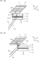
Im Hinblick auf die Relativanordnung der verschiedenen Messstrahlen Mx1, Mx2, My1, My2, My3, My4, Mz1, Mz2 der verschiedenen Positionsmesseinrichtungen sei ferner auf die 1c verwiesen. Diese zeigt eine Frontansicht der Optikeinheit 2 mit den insgesamt acht Messstrahlen Mx1, Mx2, My1, My2, My3, My4, Mz1, Mz2 der verschiedenen With regard to the relative arrangement of the various measuring beams Mx 1 , Mx 2 , My 1 , My 2 , My 3 , My 4 , Mz 1 , Mz 2 of the various position-measuring devices is further on the 1c directed. This shows a front view of the optical unit 2 with the total of eight measuring beams Mx 1 , Mx 2 , My 1 , My 2 , My 3 , My 4 , Mz 1 , Mz 2 of the various

PositionsmesseinrichtungenPosition-measuring devices

Wie eingangs erwähnt, ist zur hochpräzisen Positionsbestimmung mit Hilfe einer derartigen Anordnung erforderlich, dass die hierbei verwendeten Maßverkörperungen, Messreflektoren und Reflektoren 4.1, 4.2 der verwendeten Positionsmesseinrichtungen einer Selbstkalibration unterzogen werden. Dies erfordert, dass jede genutzte Maßverkörperung, jeder Messreflektor bzw. jeder Reflektor 4.1, 4.2 in den Abtaststrahlengängen der eingesetzten Positionsmesseinrichtungen mittels zweier Optik- bzw. Abtasteinheiten entlang einer einzigen Abtastlinie abgetastet wird, wobei die Abtastlinie jeweils entlang der Erstreckungsrichtung der zu kalibrierenden Komponente verläuft. Hierbei sollte grundsätzlich der erforderliche Aufwand möglichst gering gehalten werden, also insbesondere keine zusätzlichen Optikeinheiten erforderlich werden. Besonders kritisch ist im Fall einer Konfiguration wie in der gezeigten Anordnung die Selbstkalibration der Beugungsgitter 4.1a, 4.1b, 4.2a, 4.2b, die an den Reflektoren 4.1, 4.2 angeordnet sind und u.a. zur hochgenauen optischen Positionserfassung entlang der zweiten Hauptbewegungsachse x und entlang der dritten Achse z über die dritte und zweite Positionsmesseinrichtung dienen. Eine schematisierte Ansicht der Unterseite der Reflektoren 4.1, 4.2 mit den darauf angeordneten Beugungsgittern 4.1a, 4.1b, 4.2a, 4.2b ist in 1e gezeigt. Im vorliegenden Ausführungsbeispiel sind diese Beugungsgitter 4.1a, 4.1b, 4.2a, 4.2b als Durchlicht-Beugungsgitter ausgebildet, die Oberseite der Reflektoren 4.1, 4.2 ist mit einem Spiegel versehen, dessen reflektierende Seite in Richtung der Durchlicht-Beugungsgitter orientiert ist; die Reflektoren 4.1, 4.2 sind demzufolge jeweils als Durchlichtgitter-Spiegel-Einheit ausgebildet. Zur gewünschten Selbstkalibration dieser Komponenten ist grundsätzlich die Zuschaltung mindestens einer zweiten Optikeinheit bzw. Abtastoptik erforderlich, um aus den erzeugten Positionssignalen der jeweiligen primären Positionsmesseinrichtungen und der Positionssignale der zusätzlichen Optikeinheiten Selbstkalibrationsdaten zu erzeugen.As mentioned above, the high-precision position determination with the aid of such an arrangement is required that the material measures, measuring reflectors and reflectors used in this case 4.1 . 4.2 the position measuring devices used are subjected to a self-calibration. This requires that every measuring standard used, every measuring reflector or each reflector 4.1 . 4.2 is scanned in the scanning beam paths of the position measuring devices used by means of two optical or scanning units along a single scan line, wherein the scan line extends along the direction of extension of the component to be calibrated. Here, in principle, the required effort should be kept as low as possible, so in particular no additional optical units are required. Particularly critical in the case of a configuration as in the arrangement shown is the self-calibration of diffraction grating 4.1a . 4.1b . 4.2a . 4.2b attached to the reflectors 4.1 . 4.2 are arranged and serve, inter alia, for high-precision optical position detection along the second main axis of movement x and along the third axis z via the third and second position measuring device. A schematic view of the underside of the reflectors 4.1 . 4.2 with the diffraction gratings arranged thereon 4.1a . 4.1b . 4.2a . 4.2b is in 1e shown. In the present embodiment, these diffraction gratings 4.1a . 4.1b . 4.2a . 4.2b formed as a transmitted light diffraction grating, the top of the reflectors 4.1 . 4.2 is provided with a mirror whose reflective side is oriented in the direction of the transmitted light diffraction gratings; the reflectors 4.1 . 4.2 are therefore each formed as a transmitted light mirror unit. For the desired self-calibration of these components, in principle the connection of at least one second optical unit or scanning optics is required in order to generate self-calibration data from the generated position signals of the respective primary position-measuring devices and the position signals of the additional optical units.

Erfindungsgemäß ist nunmehr im dargestellten Ausführungsbeispiel vorgesehen, zu diesem Zweck diejenige Positionsmesseinrichtung geeignet zu modifizieren, die zur Positionserfassung des Objekts 1 entlang der ersten Hauptbewegungsachse y bzw. entlang der ersten Messrichtung sowie zur Erfassung der Rotationsbewegungen Rx, Rz um die zweite Hauptbewegungsachse x und die dritte Achse z dient, d.h. die erste Positionsmesseinrichtung. Über die nachfolgend erläuterten Maßnahmen ist es somit möglich, die erste Positionsmesseinrichtung hinsichtlich der damit erfassten Messrichtung definiert umzuschalten, um so jeweils eine zweite Positionsmessung zu Kalibrationszwecken mit Hilfe dieser Positionsmesseinrichtung vorzunehmen. Neben der Positionserfassung entlang der ersten Hauptbewegungsachse y bzw. entlang der ersten Messrichtung ist eine Umschaltung der ersten Positionsmesseinrichtung dahingehend möglich, dass darüber auch eine wahlweise Positionserfassung entlang anderer Messrichtungen möglich wird, nämlich entlang der zweiten Hauptbewegungsachse x und entlang der dritten Achse z.According to the invention is now provided in the illustrated embodiment, suitably to modify that position measuring device for this purpose, which for the position detection of the object 1 along the first main axis of movement y or along the first measuring direction and for detecting the rotational movements Rx, Rz around the second main axis of movement x and the third axis z, ie the first position measuring device. By means of the measures explained below, it is thus possible to switch the first position-measuring device in a defined manner with respect to the measuring direction detected thereby, in order to carry out a second position measurement for calibration purposes with the aid of this position-measuring device. In addition to the position detection along the first main axis of movement y or along the first measuring direction, a switching of the first position measuring device is possible in that also an optional position detection along other measuring directions is possible, namely along the second main axis of movement x and along the third axis z.

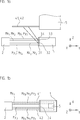
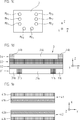
Anhand der stark vereinfachten Darstellungen in den 2a, 2b wird nachfolgend veranschaulicht, wie eine zweite Abtastung des Reflektors 4.1´ bzw. des darauf angeordneten Beugungsgitters 4.1b´ entlang von dessen Längserstreckungsrichtung y bzw. entlang der Abtastlinie L über die geeignet modifizierte erste Positionsmesseinrichtung erfolgen kann, um auf diese Art und Weise eine Selbstkalibration des Beugungsgitters 4.1b´ zu ermöglichen. Das Beugungsgitter 4.1b´ des Reflektors 4.1´ dient in der gezeigten Anordnung zur Erzeugung von Positionssignalen bzgl. einer Objektbewegung entlang der dritten Achse z; in der DE 10 2012 201 393.3 wird die hierzu genutzte Positionsmesseinrichtung als erste Positionsmesseinrichtung bezeichnet, in Bezug auf den konkreten Abtaststrahlengang dieser Positionsmesseinrichtung sei ausdrücklich auf die DE 10 2012 201 393.3 verwiesen. Vorliegend ist hierbei von der zweiten Positionsmesseinrichtung die Rede.Based on the simplified representations in the 2a . 2 B is illustrated below as a second scan of the reflector 4.1 ' or the diffraction grating arranged thereon 4.1b' along the longitudinal direction y and along the scan line L via the suitably modified first position measuring device can be carried out in order in this way a self-calibration of the diffraction grating 4.1b' to enable. The diffraction grating 4.1b' of the reflector 4.1 ' used in the arrangement shown to generate position signals with respect to. Object movement along the third axis z; in the DE 10 2012 201 393.3 the position measuring device used for this purpose is referred to as the first position measuring device, with reference to the specific scanning beam path of this position measuring device is expressly to the DE 10 2012 201 393.3 directed. In the present case, the second position measuring device is mentioned here.

Es ist nunmehr erfindungsgemäß vorgesehen, in der Spur 3.4´ der Maßverkörperungs-Reflektor-Einheit 30´, die primär zur Positionserfassung entlang der ersten Hauptbewegungsachse y dient, mehrere Bereiche 3.4a´, 3.4b´ bzw. Abschnitte unterschiedlich auszubilden. Ein erster Bereich 3.4a´ ist hierbei als Messreflektor in Form eines Planspiegels ausgebildet und dient zur interferometrischen Positionserfassung entlang der ersten Hauptbewegungsachse y. Entscheidend für die gewünschte Messrichtungs-Umschaltbarkeit ist nunmehr die hiervon unterschiedliche Ausbildung mindestens eines zweiten Bereichs 3.4b´ in dieser Spur, nämlich als Maßverkörperung in Form eines Auflicht-Beugungsgitters. Die Maßverkörperung ist in diesem zweiten Bereich 3.4b´ identisch zu derjenigen Maßverkörperung ausgebildet, die in einer weiteren Spur 3.2´ auf der Maßverkörperungs-Reflektor-Einheit 30´ angeordnet ist und vom Messstrahl Mz der zweiten Positionsmesseinrichtung für die z-Achsen-Bewegung beaufschlagt wird.It is now provided according to the invention, in the lane 3.4' the Scale Reflector Unit 30' , which serves primarily for position detection along the first main axis of motion y, several areas 3.4a' . 3.4b' or form sections differently. A first area 3.4a' is here designed as a measuring reflector in the form of a plane mirror and is used for interferometric position detection along the first main axis of motion y. Decisive for the desired direction of measurement switchability is now the different formation of at least a second area 3.4b' in this track, namely as a material measure in the form of incident light diffraction grating. The material measure is in this second area 3.4b' identical to the measuring graduation formed in a further track 3.2' on the Scale Reflector Unit 30' is arranged and is acted upon by the measuring beam Mz of the second position measuring device for the z-axis movement.

Eine derartige Ausbildung der Bereiche 3.4a´, 3.4b´ in der Spur 3.4 ermöglicht nunmehr die erfindungsgemäße Umschaltung der Messrichtungen der ersten Positionsmesseinrichtung, wie dies in den 2a, 2b veranschaulicht wird. Such a training of the areas 3.4a' . 3.4b' in the track 3.4 now allows the inventive switching of the measuring directions of the first position measuring device, as shown in the 2a . 2 B is illustrated.

In der Mess- bzw. Maschinenstellung gemäß 2a befindet sich das Objekt und damit die Maßverkörperungs-Reflektoreinheit 30´ entlang der zweiten Hauptbewegungsachse x in einer Position, in der der Messstrahl My der ersten Positionsmesseinrichtung auf den Bereich 3.4a´ trifft, d.h. auf den beispielsweise als Planspiegel ausgebildeten Messreflektor. Von dort wird der Messstrahl My in Richtung der – nicht dargestellten Optikeinheit zurückreflektiert. In dieser Messstellung arbeitet die erste Positionsmesseinrichtung in bekannter Art und Weise und dient u.a. zur Erfassung der Objekt-Position entlang der ersten Hauptbewegungsachse y. Der in 2a ebenfalls dargestellte Messstrahl Mz der zweiten Positionsmesseinrichtung beaufschlagt in dieser Position die Spur 3.2´ mit der dort angeordneten Maßverkörperung sowie das Beugungsgitter des Reflektors 4.1´. Über die zugehörige zweite Positionsmesseinrichtung ist die Erfassung der Objektposition entlang der zweiten Messrichtung bzw. der dritten Achse z möglich.In the measuring or machine position according to 2a there is the object and thus the material measure reflector unit 30' along the second main axis of movement x in a position in which the measuring beam My of the first position measuring device to the area 3.4a' meets, that is, on the trained example as a plane mirror measuring reflector. From there, the measuring beam My is reflected back in the direction of the optical unit - not shown. In this measuring position, the first position measuring device operates in a known manner and is used inter alia for detecting the object position along the first main axis of motion y. The in 2a measurement beam Mz of the second position-measuring device likewise shown acts on the track in this position 3.2' with the material measure arranged there and the diffraction grating of the reflector 4.1 ' , About the associated second position measuring device, the detection of the object position along the second measuring direction or the third axis z is possible.

Verfährt das Objekt bzw. die Maßverkörperungs-Reflektoreinheit 30´ entlang der zweiten Hauptbewegungsachse x nunmehr in die Selbstkalibrations-Position für die dritte Achse z, wie dies in 2b gezeigt ist, so trifft der Messstrahl My der ersten Positionsmesseinrichtung dann auf den zweiten Bereich 3.4b´ in der entsprechenden Spur 3.4´. Wie ersichtlich, bewirkt die dort angeordnete Maßverkörperung eine Umlenkung des Messstrahls My´ analog zur Umlenkung des Messstrahls Mz der zweiten Positionsmesseinrichtung in Richtung des zu kalibrierenden Beugungsgitters 4.1b´ auf dem Reflektor 4.1´. Das Beugungsgitter 4.1b´ auf dem Reflektor 4.1´ wird bei einer resultierenden Objektbewegung entlang der ersten Hauptbewegungsrichtung y nunmehr entlang der Abtastlinie L zweifach abgetastet, d.h. entlang der ersten Hauptbewegungsachse y bzw. entlang der ersten Messrichtung. Eine Selbstkalibration des Beugungsgitters 4.1b´ auf dem Reflektor 4.1´ ist somit möglich, ohne dass hierzu eine zusätzliche Optik- bzw. Abtasteinheit erforderlich ist. Die erste Positionsmesseinrichtung, die eigentlich primär für die Positionserfassung entlang der ersten Messrichtung respektive der ersten Hauptbewegungsachse y dient, kann in dieser Position derart umgeschaltet werden, dass darüber auch eine Positionserfassung entlang einer anderen Messrichtung, nämlich entlang der dritten Achse z, möglich ist. Zusammen mit den verfügbaren Positionssignalen der für diese Achse z vorgesehenen zweiten Positionsmesseinrichtung ist eine Selbstkalibration der Reflektoren 4.1´ entlang ihrer Längserstreckungsrichtung möglich, die der ersten Hauptbewegungsachse y entspricht. Während der Verfahrbewegung entlang der ersten Hauptbewegungsachse y werden die erzeugten Positionssignale der ersten und zweiten Positionsmesseinrichtung einer geeigneten – nicht gezeigten – Kalibrationseinheit zugeführt.Moves the object or the material measure reflector unit 30' along the second main axis of movement x now into the self-calibration position for the third axis z, as shown in FIG 2 B is shown, the measuring beam My of the first position measuring device then hits the second area 3.4b' in the appropriate lane 3.4' , As can be seen, the dimensional standard arranged there causes a deflection of the measuring beam My 'analogously to the deflection of the measuring beam Mz second position measuring device in the direction of the diffraction grating to be calibrated 4.1b' on the reflector 4.1 ' , The diffraction grating 4.1b' on the reflector 4.1 ' is scanned twice in a resulting object movement along the first main movement direction y along the scan line L, ie along the first main axis of motion y and along the first measuring direction. A self-calibration of the diffraction grating 4.1b' on the reflector 4.1 ' is thus possible without requiring an additional optical or scanning unit is required. The first position measuring device, which actually serves primarily for the position detection along the first measuring direction or the first main axis of movement y, can be switched in this position such that a position detection along another measuring direction, namely along the third axis z, is also possible. Together with the available position signals of the z provided for this second position measuring device is a self-calibration of the reflectors 4.1 ' along its longitudinal direction possible, which corresponds to the first main axis of movement y. During the movement along the first main axis of movement y, the generated position signals are fed to the first and second position-measuring devices of a suitable calibration unit (not shown).

Basierend auf diesem Prinzip können neben den Beugungsgittern 4.1b, 4.2b auch die Beugungsgitter 4.1a, 4.2a auf den Reflektoren 4.1, 4.2 der Anordnung aus den 1a1e einer Selbstkalibration entlang der ersten Hauptbewegungsrichtung y unterzogen werden. Die Beugungsgitter 4.1a, 4.2a sind in der dritten Positionsmesseinrichtung der vorliegenden Anordnung vorgesehen, über die eine Positionserfassung des Objekts 1 entlang der zweiten Hauptbewegungsachse x erfolgt. Im Hinblick auf den Abtaststrahlengang dieser Positionsmesseinrichtung sei wieder ausdrücklich auf die DE 10 2012 201 393.3 , wo diese Positionsmesseinrichtung als zweite Positionsmesseinrichtung bezeichnet wird. Um die erste Positionsmesseinrichtung zur Erfassung der Objektbewegung entlang der ersten Hauptbewegungsachse y auch in diese Messrichtung umzuschalten, umfasst die Maßverkörperungs-Reflektor-Einheit 3 eine weitere Spur 3.1 mit unterschiedlich ausgebildeten Bereichen 3.1a, 3.1b, wie dies aus 1d ersichtlich ist. Während der Bereich 3.1a als Messreflektor für die Positionserfassung der ersten Positionsmesseinrichtung entlang der ersten Hauptbewegungsachse y ausgebildet ist, sind die Bereiche 3.1b mit einer Maßverkörperung versehen, um in diesen Positionen jeweils eine Ab- bzw. Umlenkung des darauf einfallenden Messstrahls in Richtung der Beugungsgitter 4.1a, 4.2a auf den Reflektoren 4.1, 4.2 zu bewirken und darüber eine zweite Abtastung derselbigen zu ermöglichen, wenn in dieser Stellung eine Objektbewegung entlang der ersten Hauptbewegungsachse y erfolgt. In diesem Fall werden die Positionssignale der umgeschalteten ersten Positionsmesseinrichtung und der dritten Positionsmesseinrichtung einer wiederum nicht dargestellten Kalibrationseinheit zugeführt.Based on this principle, in addition to the diffraction gratings 4.1b . 4.2b also the diffraction grids 4.1a . 4.2a on the reflectors 4.1 . 4.2 the arrangement of the 1a - 1e a self-calibration along the first main movement direction y be subjected. The diffraction gratings 4.1a . 4.2a are provided in the third position measuring device of the present arrangement, via which a position detection of the object 1 takes place along the second main axis of movement x. With regard to the scanning beam path of this position measuring device is explicitly on the DE 10 2012 201 393.3 where this position measuring device is referred to as the second position measuring device. In order to switch the first position measuring device for detecting the movement of the object along the first main axis of movement y also in this measuring direction, the measuring graduation reflector unit comprises 3 another track 3.1 with differently shaped areas 3.1a . 3.1b like this 1d is apparent. While the area 3.1a is formed as a measuring reflector for the position detection of the first position measuring device along the first main axis of movement y, the areas are 3.1b provided with a material measure to each in these positions a deflection or deflection of the incident thereon measuring beam in the direction of the diffraction grating 4.1a . 4.2a on the reflectors 4.1 . 4.2 to cause and about a second scan derselbigen to allow, if in this position, an object movement along the first main axis of movement y occurs. In this case, the position signals of the switched first position-measuring device and the third position-measuring device are fed to a calibration unit, not shown again.

Über die erfindungsgemäßen Maßnahmen ist somit in der beschriebenen Anordnung eine Selbstkalibration von bestimmten Komponenten möglich, ohne dass hierbei zusätzlicher Aufwand auf Seiten der Optik- bzw. Abtasteinheit 2 der eingesetzten Positionsmesseinrichtungen erforderlich ist. Möglich wird dies durch die gezielte Umschaltung der Messrichtung in einer der verwendeten Positionsmesseinrichtungen, im vorliegenden Fall der ersten Positionsmesseinrichtung. Diese kann somit in bestimmten Maschinenstellungen bzw. Kalibrationspositionen für die zur Selbstkalibration erforderliche zweite optische Abtastung der entsprechenden Komponenten und zur Erzeugung entsprechender Positionssignale herangezogen werden. About the measures according to the invention thus a self-calibration of certain components is possible in the described arrangement, without this additional effort on the part of the optical or scanning unit 2 the position measuring devices used is required. This is made possible by the targeted switching of the measuring direction in one of the position measuring devices used, in the present case the first position measuring device. This can thus be used in certain machine positions or calibration positions for the required for self-calibration second optical scanning of the corresponding components and for generating corresponding position signals.

Wie oben erwähnt, ist die erfindungsgemäß ausgebildete erste Positionsmesseinrichtung in der erläuterten Anordnung als 4-Achs-Interferometer ausgebildet. Darüber ist gewährleistet, dass etwa auch während der erfolgenden Selbstkalibration der Reflektoren entlang der ersten Hauptbewegungsachse y, z.B. mittels eines entsprechend umgelenkten Messstrahls My1, eine Bestimmung der Position und Orientierung des Objekts über die drei anderen Messstrahlen My2, My3 und My4 möglich ist. As mentioned above, the inventively designed first position measuring device is formed in the illustrated arrangement as a 4-axis interferometer. In addition, it is ensured that, for example, during the self-calibration of the reflectors along the first main axis of movement y, eg by means of a correspondingly deflected measuring beam My 1 , a determination of the position and orientation of the object via the three other measuring beams My 2 , My 3 and My 4 possible is.

Die gewünschte Messrichtung, entlang der eine Abtastung bzw. Positionserfassung erfolgen soll, wird erfindungsgemäß ausschließlich durch geeignete Modifikationen auf Seiten der Maßverkörperungs-Reflektor-Einheit 3 eingestellt; eine Draufsicht auf diese ist in 1d gezeigt. Auf Seiten der Optikeinheit 2 der ersten Positionsmesseinrichtung sind keine Änderungen erforderlich. In den erfindungsgemäß unterschiedlich ausgebildeten Bereichen 3.4a, 3.4b bzw. 3.1a, 3.1b in den Spuren 3.1, 3.4 der Maßverkörperungs-Reflektor-Einheit 3 erfahren die darauf einfallenden Strahlenbündel der entsprechenden Messstrahlen jeweils unterschiedliche Umlenk- und/oder Ablenkwirkungen. Als vorteilhaft erweist sich, wenn ein erster Bereich 3.1a, 3.4a, der zur Erzeugung der primären Positionssignale der jeweiligen Positionsmesseinrichtung dient, sich über einen Großteil der Spur 3.1, 3.4 erstreckt und der zweite, unterschiedlich ausgebildete Bereich 3.1b, 3.4b, der zur Positionssignalerzeugung im umgeschalteten Betrieb dient, sich lediglich über einen deutlich kleineren Bereich der Spur 3.1, 3.4 erstreckt. So kann wie im obigen Ausführungsbeispiel vorgesehen, der erste Bereich 3.1a, 3.4a zentral in der Spur 3.1, 3.4 angeordnet werden, und lediglich an mindestens einem Ende ein unterschiedlich ausgebildeter zweiter Bereich 3.1b, 3.4b vorgesehen werden, wie dies im dargestellten Ausführungsbeispiel der Maßverkörperungs-Reflektor-Einheit 3 in 1d realisiert ist.The desired measuring direction, along which a scanning or position detection is to take place, according to the invention exclusively by suitable modifications on the part of the material measure reflector unit 3 set; a plan view of this is in 1d shown. On the side of the optical unit 2 the first position measuring device no changes are required. In the present invention differently shaped areas 3.4a . 3.4b respectively. 3.1a . 3.1b in the tracks 3.1 . 3.4 the Scale Reflector Unit 3 experience the incident thereon beams of the respective measuring beams each different deflection and / or deflection effects. It proves to be advantageous if a first area 3.1a . 3.4a which serves to generate the primary position signals of the respective position-measuring device, over a majority of the track 3.1 . 3.4 extends and the second, differently formed area 3.1b . 3.4b , which serves for position signal generation in the switched mode, only over a much smaller area of the track 3.1 . 3.4 extends. Thus, as provided in the above embodiment, the first area 3.1a . 3.4a centrally in the lane 3.1 . 3.4 are arranged, and only at at least one end a differently shaped second Area 3.1b . 3.4b be provided, as in the illustrated embodiment of the measuring-reflector unit 3 in 1d is realized.

Eine derartige Messrichtungs-Umschaltung, basierend auf den erfindungsgemäßen Überlegungen, kann auch in anderen Anwendungsfällen unabhängig von der diskutierten Selbstkalibrierung zum Einsatz kommen. Beispielsweise kann es vorteilhaft sein, an einer bestimmten Position eines Tisches eine einzelne Messrichtung besonders genau oder aber mit verringertem Abbé-Abstand zu erfassen, um beispielsweise eine Referenzmarke anzutasten. Durch Umschalten einer redundanten Messachse von einer anderen, im sonstigen Betrieb genutzten Messrichtung in die besonders genau zu erfassende Messrichtung lassen sich Positionen entlang dieser Messachse redundant und damit genauer messen.Such a measuring direction switching, based on the inventive considerations, can also be used in other applications, regardless of the discussed self-calibration. For example, it may be advantageous to detect a single measuring direction particularly precisely or at a reduced Abbe distance at a specific position of a table in order, for example, to touch a reference mark. By switching a redundant measuring axis from another measuring direction used in the other operation to the measuring direction which is to be detected particularly accurately, positions along this measuring axis can be measured redundantly and thus more accurately.

ZITATE ENTHALTEN IN DER BESCHREIBUNG QUOTES INCLUDE IN THE DESCRIPTION

Diese Liste der vom Anmelder aufgeführten Dokumente wurde automatisiert erzeugt und ist ausschließlich zur besseren Information des Lesers aufgenommen. Die Liste ist nicht Bestandteil der deutschen Patent- bzw. Gebrauchsmusteranmeldung. Das DPMA übernimmt keinerlei Haftung für etwaige Fehler oder Auslassungen.This list of the documents listed by the applicant has been generated automatically and is included solely for the better information of the reader. The list is not part of the German patent or utility model application. The DPMA assumes no liability for any errors or omissions.

Zitierte PatentliteraturCited patent literature

  • DE 102012201393 [0003, 0038, 0038, 0040, 0041, 0042, 0043, 0047, 0047, 0052] DE 102012201393 [0003, 0038, 0038, 0040, 0041, 0042, 0043, 0047, 0047, 0052]

Zitierte Nicht-PatentliteraturCited non-patent literature

  • „Exact wavefront reconstruction from two lateral shearing interferograms“, C. Elster, I. Weingärtner in Vol. 16, No. 9, Sept 1999, J. Opt. Soc. Am. A, 2281–2285 [0004] "Exact wavefront reconstruction from two lateral shearing interferograms", C. Elster, I. Weingartner in Vol. 16, no. 9, Sept. 1999, J. Opt. Soc. At the. A, 2281-2285 [0004]

Claims (14)

Positionsmesseinrichtung zur Erfassung der Position eines ersten Objekts (1) in Bezug auf ein zweites Objekt (5), wobei das erste und das zweite Objekt entlang mindestens zweier Messrichtungen (x, y, z) relativ zueinander beweglich angeordnet sind, mit – einer Optikeinheit (2), die mit einem der beiden Objekte (5) verbunden ist und mindestens eine Lichtquelle, eine Detektoranordnung sowie weitere optische Elemente in definierter Anordnung umfasst und – einer Maßverkörperungs-Reflektor-Einheit (3, 30´), welche am anderen Objekt (1) angeordnet ist und mindestens zwei unterschiedlich ausgebildete Bereiche (3.1a, 3.1b, 3.4a, 3.4b, 3.4a´, 3.4b´) in einer Spur (3.1, 3.4, 3.4´) aufweist, die zur Positionserfassung mit der Optikeinheit (2) optisch abtastbar sind, wobei über die unterschiedliche Ausbildung der Bereiche (3.1a, 3.1b, 3.4a, 3.4b, 3.4a´, 3.4b´) bei der Positionserfassung eine Umschaltung zwischen den verschiedenen Messrichtungen (x, y, z) möglich ist und für jede Messrichtung (x, y, z) mit der Optikeinheit (2) jeweils Positionssignale bezüglich der Relativbewegung der beiden Objekte (1, 5) erzeugbar sind.Position measuring device for detecting the position of a first object ( 1 ) with respect to a second object ( 5 ), wherein the first and the second object along at least two measuring directions (x, y, z) are arranged to be movable relative to each other, with - an optical unit ( 2 ) with one of the two objects ( 5 ) and at least one light source, a detector arrangement and further optical elements in a defined arrangement, and - a measuring-reflector unit ( 3 . 30' ), which at the other object ( 1 ) and at least two differently formed areas ( 3.1a . 3.1b . 3.4a . 3.4b . 3.4a' . 3.4b' ) in a track ( 3.1 . 3.4 . 3.4' ), which is used for position detection with the optical unit ( 2 ) are optically scanned, whereby the different formation of the areas ( 3.1a . 3.1b . 3.4a . 3.4b . 3.4a' . 3.4b' ) in the position detection a switching between the different measuring directions (x, y, z) is possible and for each measuring direction (x, y, z) with the optical unit ( 2 ) each position signals with respect to the relative movement of the two objects ( 1 . 5 ) are producible. Positionsmesseinrichtung nach Anspruch 1, wobei in den unterschiedlichen Bereichen (3.1a, 3.1b, 3.4a, 3.4b, 3.4a´, 3.4b´) der Spur (3.1, 3.4, 3.4´) der Maßverkörperungs-Reflektor-Einheit (3, 30´) Messreflektoren und Maßverkörperungen angeordnet sind. Position measuring device according to claim 1, wherein in the different regions ( 3.1a . 3.1b . 3.4a . 3.4b . 3.4a' . 3.4b' ) the trace ( 3.1 . 3.4 . 3.4' ) the scale reflector unit ( 3 . 30' ) Measuring reflectors and measuring standards are arranged. Positionsmesseinrichtung nach Anspruch 2, wobei die Messreflektoren als Planspiegel und die Maßverkörperungen als Auflicht-Beugungsgitter ausgebildet sind.Position measuring device according to claim 2, wherein the measuring reflectors are designed as a plane mirror and the measuring graduations as reflected-light diffraction gratings. Positionsmesseinrichtung nach Anspruch 2, wobei Strahlenbündel, die auf die unterschiedlich ausgebildeten Bereiche (3.1a, 3.1b, 3.4a, 3.4b, 3.4a´, 3.4b´) auftreffen unterschiedliche Umlenk- und/oder Ablenkwirkungen erfahren.Position measuring device according to claim 2, wherein radiation beams which act on the differently formed regions ( 3.1a . 3.1b . 3.4a . 3.4b . 3.4a' . 3.4b' ) experience different deflection and / or deflection effects. Positionsmesseinrichtung nach Anspruch 1, wobei die Maßverkörperungs-Reflektor-Einheit (3, 30´) mehrere parallel angeordnete Spuren (3.13.4, 3.1´3.4´) aufweist, in denen Maßverkörperungen und/oder Messreflektoren angeordnet sind.Position measuring device according to claim 1, wherein the scale reflector unit ( 3 . 30' ) several parallel tracks ( 3.1 - 3.4 . 3.1' - 3.4' ), in which scale graduations and / or measuring reflectors are arranged. Positionsmesseinrichtung nach Anspruch 5, wobei – in einer Spur (3.2, 3.3, 3.2´) eine Maßverkörperung angeordnet ist und – in einer weiteren Spur (3.1, 3.4, 3.4´) in einem ersten Bereich (3.1a, 3.4a, 3.4a´) ein Messreflektor angeordnet ist und in einem zweiten Bereich (3.1b, 3.4b, 3.4b´) eine Maßverkörperung angeordnet ist, die identisch zur Maßverkörperung in der anderen Spur (3.2, 3.3, 3.2´) ausgebildet ist.Position measuring device according to claim 5, wherein - in a track ( 3.2 . 3.3 . 3.2' ) a material measure is arranged and - in a further track ( 3.1 . 3.4 . 3.4' ) in a first area ( 3.1a . 3.4a . 3.4a' ) a measuring reflector is arranged and in a second area ( 3.1b . 3.4b . 3.4b' ) a material measure is arranged, which is identical to the material measure in the other track ( 3.2 . 3.3 . 3.2' ) is trained. Positionsmesseinrichtung nach mindestens einem der vorhergehenden Ansprüche, wobei entlang der Erstreckungsrichtung der Spur (3.1, 3.4, 3.4´) ein zentraler erster Bereich (3.1a, 3.4a, 3.4a´) in der Spur (3.1, 3.4, 3.4´) angeordnet ist und mindestens an einem Ende des ersten Bereichs ein unterschiedlich ausgebildeter zweiter Bereich (3.1b, 3.4b, 3.4b´) in der Spur (3.1, 3.4, 3.4´) angeordnet ist.Position measuring device according to at least one of the preceding claims, wherein along the extension direction of the track ( 3.1 . 3.4 . 3.4' ) a central first area ( 3.1a . 3.4a . 3.4a' ) in the track ( 3.1 . 3.4 . 3.4' ) and at least at one end of the first area a differently formed second area ( 3.1b . 3.4b . 3.4b' ) in the track ( 3.1 . 3.4 . 3.4' ) is arranged. Positionsmesseinrichtung nach mindestens einem der vorhergehenden Ansprüche, wobei in der Spur (3.1, 3.4, 3.4´) ein erster Bereich (3.1a, 3.4a, 3.4a´) angeordnet ist, der sich über den Großteil der Spur (3.1, 3.4, 3.4´) erstreckt und ein zweiter, unterschiedlich ausgebildeter Bereich (3.1b, 3.4b, 3.4b´) in der Spur (3.1, 3.4, 3.4´) angeordnet ist, der sich lediglich über einen deutlich kleineren Bereich der Spur (3.1, 3.4, 3.4´) erstreckt.Position measuring device according to at least one of the preceding claims, wherein in the track ( 3.1 . 3.4 . 3.4' ) a first area ( 3.1a . 3.4a . 3.4a' ), which extends over the majority of the track ( 3.1 . 3.4 . 3.4' ) and a second, differently formed area ( 3.1b . 3.4b . 3.4b' ) in the track ( 3.1 . 3.4 . 3.4' ), which extends only over a significantly smaller area of the track ( 3.1 . 3.4 . 3.4' ). Anordnung mit einer ersten Positionsmesseinrichtung nach einem der vorhergehenden Ansprüche und mit – einem ersten Objekt (1), das entlang zweier orthogonaler, erster und zweiter Hauptbewegungsachsen (y, x) sowie entlang einer hierzu dritten Achse (z) beweglich angeordnet ist, wobei – die erste Hauptbewegungsachse (y) als erste Messrichtung fungiert, – die dritte Achse (z) als zweite Messrichtung und – die zweite Hauptbewegungsachse (x) als dritte Messrichtung und – einem zweiten Objekt (5), das stationär gegenüber dem ersten Objekt angeordnet ist, wobei die Optikeinheit (2) am zweiten Objekt (5) angeordnet ist und wobei – am ersten Objekt (1) die sich entlang der zweiten Hauptbewegungsachse (x) erstreckende Maßverkörperungs-Reflektor-Einheit (3) angeordnet ist, die eine Spur (3.1, 3.4) mit einem ersten Bereich (3.1a, 3.4a) mit einem Messreflektor und einen zweiten Bereich (3.1b, 3.4b) mit einer Maßverkörperung umfasst, so dass bei der optischen Abtastung des ersten Bereichs (3.1a, 3.4a) Positionssignale bezüglich einer Bewegung des ersten Objekts (1) entlang der ersten Messrichtung (y) erzeugbar sind und bei der optischen Abtastung des zweiten Bereichs (3.1b, 3.4b) weitere Positionssignale bezüglich einer Bewegung des ersten Objekts (1) entlang der zweiten Messrichtung (x) oder entlang der dritten Messrichtung (z) erzeugbar sind.Arrangement with a first position-measuring device according to one of the preceding claims and with a first object ( 1 ) arranged along two orthogonal, first and second main axes of motion (y, x) and along a third axis (z), wherein - the first main axis of motion (y) acts as the first direction of measurement, - the third axis (z) as second measuring direction and - the second main axis of movement (x) as a third measuring direction and - a second object ( 5 ), which is arranged stationary relative to the first object, wherein the optical unit ( 2 ) on the second object ( 5 ) and wherein - at the first object ( 1 ) the measuring scale reflector unit (2) extending along the second main axis of movement (x) 3 ) which is a track ( 3.1 . 3.4 ) with a first area ( 3.1a . 3.4a ) with a measuring reflector and a second area ( 3.1b . 3.4b ) with a material measure such that in the optical scanning of the first region ( 3.1a . 3.4a ) Position signals relating to a movement of the first object ( 1 ) are producible along the first measuring direction (y) and in the optical scanning of the second region ( 3.1b . 3.4b ) further position signals with respect to a movement of the first object ( 1 ) along the second measuring direction (x) or along the third measuring direction (z) are generated. Anordnung nach Anspruch 9, die eine zweite Positionsmesseinrichtung umfasst, über die Positionssignale bezüglich einer Bewegung des ersten Objekts (1) entlang der zweiten Messrichtung (z) erzeugbar sind. Arrangement according to claim 9, comprising a second position measuring device, over which Position signals relating to a movement of the first object ( 1 ) are producible along the second measuring direction (z). Anordnung nach Anspruch 9, die eine dritte Positionsmesseinrichtung umfasst, über die Positionssignale bezüglich einer Bewegung des ersten Objekts (1) entlang der dritten Messrichtung (x) erzeugbar sind.Arrangement according to Claim 9, comprising a third position-measuring device, via the position signals relating to a movement of the first object ( 1 ) along the third measuring direction (x) can be generated. Anordnung nach Anspruch 10 oder 11, wobei im Fall der optischen Abtastung der Maßverkörperung im zweiten Bereich und der gleichzeitigen Erzeugung von Positionssignalen mittels der zweiten oder dritten Positionsmesseinrichtung während einer Verfahrbewegung entlang der ersten Messrichtung (y) jeweils eine zweifache Abtastung eines Reflektors (4.1, 4.2) der zweiten oder dritten Positionsmesseinrichtung entlang der ersten Messrichtung (y) erfolgt.Arrangement according to claim 10 or 11, wherein in the case of the optical scanning of the material measure in the second region and the simultaneous generation of position signals by the second or third position measuring device during a movement along the first measuring direction (y) in each case a double scanning of a reflector ( 4.1 . 4.2 ) of the second or third position-measuring device takes place along the first measuring direction (y). Anordnung nach Anspruch 12, wobei – die Positionssignale der ersten und zweiten Positionsmesseinrichtung einer Kalibrationseinheit zuführbar sind und/oder – die Positionssignale der ersten und dritten Positionsmesseinrichtung einer Kalibrationseinheit zuführbar sind.Arrangement according to claim 12, wherein - The position signals of the first and second position measuring device of a calibration unit can be fed and or - The position signals of the first and third position measuring device of a calibration unit can be fed. Anordnung nach Anspruch 9, wobei die erste Positionsmesseinrichtung als Mehrachs-Interferometer mit vier Messstrahlen (My1, My2, My3, My4) ausgebildet ist.Arrangement according to claim 9, wherein the first position measuring device is designed as a multi-axis interferometer with four measuring beams (My 1 , My 2 , My 3 , My 4 ).
DE102012204572A 2012-03-22 2012-03-22 Position measuring device and arrangement with such a position measuring device Withdrawn DE102012204572A1 (en)

Priority Applications (6)

Application Number Priority Date Filing Date Title
DE102012204572A DE102012204572A1 (en) 2012-03-22 2012-03-22 Position measuring device and arrangement with such a position measuring device
EP13157956.7A EP2642254B1 (en) 2012-03-22 2013-03-06 Assembly comprising a first and a second position measuring device
KR1020130025270A KR101864770B1 (en) 2012-03-22 2013-03-08 Position-measuring device and system having such a position-measuring device
US13/845,988 US9389065B2 (en) 2012-03-22 2013-03-18 Position-measuring device and system having such a position-measuring device
JP2013056864A JP6278605B2 (en) 2012-03-22 2013-03-19 Position measuring device and structure provided with such position measuring device
CN201310093649.8A CN103322910B (en) 2012-03-22 2013-03-22 Position measurement apparatus and the device with this position measurement apparatus

Applications Claiming Priority (1)

Application Number Priority Date Filing Date Title
DE102012204572A DE102012204572A1 (en) 2012-03-22 2012-03-22 Position measuring device and arrangement with such a position measuring device

Publications (1)

Publication Number Publication Date
DE102012204572A1 true DE102012204572A1 (en) 2013-09-26

Family

ID=47827024

Family Applications (1)

Application Number Title Priority Date Filing Date
DE102012204572A Withdrawn DE102012204572A1 (en) 2012-03-22 2012-03-22 Position measuring device and arrangement with such a position measuring device

Country Status (6)

Country Link
US (1) US9389065B2 (en)
EP (1) EP2642254B1 (en)
JP (1) JP6278605B2 (en)
KR (1) KR101864770B1 (en)
CN (1) CN103322910B (en)
DE (1) DE102012204572A1 (en)

Families Citing this family (20)

* Cited by examiner, † Cited by third party
Publication number Priority date Publication date Assignee Title
KR102088685B1 (en) 2012-12-19 2020-03-13 바스프 에스이 Detector for optically detecting at least one object
WO2014198629A1 (en) 2013-06-13 2014-12-18 Basf Se Detector for optically detecting at least one object
KR20160019067A (en) 2013-06-13 2016-02-18 바스프 에스이 Detector for optically detecting an orientation of at least one object
WO2015024871A1 (en) 2013-08-19 2015-02-26 Basf Se Optical detector
JP6483127B2 (en) 2013-08-19 2019-03-13 ビーエーエスエフ ソシエタス・ヨーロピアBasf Se Detector for determining the position of at least one object
CN106662636B (en) 2014-07-08 2020-12-25 巴斯夫欧洲公司 Detector for determining a position of at least one object
US10094927B2 (en) 2014-09-29 2018-10-09 Basf Se Detector for optically determining a position of at least one object
KR102497704B1 (en) 2014-12-09 2023-02-09 바스프 에스이 Optical detector
JP6841769B2 (en) 2015-01-30 2021-03-10 トリナミクス ゲゼルシャフト ミット ベシュレンクテル ハフツング Detector that optically detects at least one object
EP3325917B1 (en) 2015-07-17 2020-02-26 trinamiX GmbH Detector for optically detecting at least one object
US10412283B2 (en) 2015-09-14 2019-09-10 Trinamix Gmbh Dual aperture 3D camera and method using differing aperture areas
EP3491675B1 (en) 2016-07-29 2022-11-16 trinamiX GmbH Optical sensor and detector for optical detection
US11428787B2 (en) 2016-10-25 2022-08-30 Trinamix Gmbh Detector for an optical detection of at least one object
WO2018077870A1 (en) 2016-10-25 2018-05-03 Trinamix Gmbh Nfrared optical detector with integrated filter
KR102452770B1 (en) 2016-11-17 2022-10-12 트리나미엑스 게엠베하 A detector for optically detecting at least one object
US11860292B2 (en) 2016-11-17 2024-01-02 Trinamix Gmbh Detector and methods for authenticating at least one object
WO2018193045A1 (en) 2017-04-20 2018-10-25 Trinamix Gmbh Optical detector
US11067692B2 (en) 2017-06-26 2021-07-20 Trinamix Gmbh Detector for determining a position of at least one object
JP7141313B2 (en) * 2018-11-06 2022-09-22 Dmg森精機株式会社 Displacement detector
CN111721210B (en) * 2020-06-19 2021-11-12 深圳市汉森软件有限公司 Initialization method, device, equipment and medium after conversion of logical raster resolution

Citations (1)

* Cited by examiner, † Cited by third party
Publication number Priority date Publication date Assignee Title
DE102012201393A1 (en) 2012-02-01 2013-08-01 Dr. Johannes Heidenhain Gmbh Position measuring device and arrangement with several position measuring devices

Family Cites Families (23)

* Cited by examiner, † Cited by third party
Publication number Priority date Publication date Assignee Title
JPH08247790A (en) * 1995-03-10 1996-09-27 Sefuto Kenkyusho:Kk Position detection apparatus
DE19633337A1 (en) * 1996-08-07 1998-02-12 Harry Prof Dr Ing Trumpold Position measuring system for moving relative to each other objects
JP4576014B2 (en) * 1999-12-21 2010-11-04 オリンパス株式会社 Optical encoder
DE10144659A1 (en) * 2000-09-14 2002-05-02 Heidenhain Gmbh Dr Johannes Position measuring device for detecting the relative position of a scanning unit, comprising at least one scanning grating unit, a deviating element in the form of a ridge prism, and a plurality of optoelectric detectors
US7102729B2 (en) * 2004-02-03 2006-09-05 Asml Netherlands B.V. Lithographic apparatus, measurement system, and device manufacturing method
DE102005029917A1 (en) * 2005-06-28 2007-01-04 Dr. Johannes Heidenhain Gmbh Position measuring device
JP4593625B2 (en) * 2005-09-21 2010-12-08 パナソニック株式会社 Angle measuring apparatus and method
JP4932284B2 (en) * 2006-03-03 2012-05-16 株式会社ミツトヨ Photoelectric encoder
JP4601006B2 (en) 2006-09-29 2010-12-22 本田技研工業株式会社 Air cleaner device
JP2008108906A (en) * 2006-10-25 2008-05-08 Canon Inc Positioning device
JP5147368B2 (en) * 2006-11-20 2013-02-20 ドクトル・ヨハネス・ハイデンハイン・ゲゼルシヤフト・ミツト・ベシユレンクテル・ハフツング Encoder
DE102007035345A1 (en) 2006-11-20 2008-05-21 Dr. Johannes Heidenhain Gmbh Position measuring device
DE102008008873A1 (en) * 2007-05-16 2008-11-20 Dr. Johannes Heidenhain Gmbh Position measuring device
US8174671B2 (en) * 2007-06-21 2012-05-08 Asml Netherlands B.V. Lithographic projection apparatus and method for controlling a support structure
US7804579B2 (en) * 2007-06-21 2010-09-28 Asml Netherlands B.V. Control system, lithographic projection apparatus, method of controlling a support structure, and a computer program product
US8208128B2 (en) * 2008-02-08 2012-06-26 Nikon Corporation Position measuring system and position measuring method, Movable body apparatus, movable body drive method, exposure apparatus and exposure method, pattern forming apparatus, and device manufacturing method
KR20100041024A (en) * 2008-10-13 2010-04-22 한국표준과학연구원 Apparatus for six-degree-of-freedom displacement measurement using a two-dimensional grating
JP4283878B2 (en) 2008-10-24 2009-06-24 キヤノンアネルバ株式会社 Magnetron sputtering equipment
JP2010205867A (en) * 2009-03-03 2010-09-16 Canon Inc Position detector and aligner
KR101078781B1 (en) * 2010-02-01 2011-11-01 주식회사 고영테크놀러지 Method of inspecting a three dimensional shape
US8300233B2 (en) * 2010-03-30 2012-10-30 Zygo Corporation Interferometric encoder systems
JP5656467B2 (en) * 2010-06-17 2015-01-21 Dmg森精機株式会社 Position detection device
JP5754971B2 (en) * 2011-02-14 2015-07-29 キヤノン株式会社 Shape measuring apparatus and shape measuring method

Patent Citations (1)

* Cited by examiner, † Cited by third party
Publication number Priority date Publication date Assignee Title
DE102012201393A1 (en) 2012-02-01 2013-08-01 Dr. Johannes Heidenhain Gmbh Position measuring device and arrangement with several position measuring devices

Non-Patent Citations (1)

* Cited by examiner, † Cited by third party
Title
"Exact wavefront reconstruction from two lateral shearing interferograms", C. Elster, I. Weingärtner in Vol. 16, No. 9, Sept 1999, J. Opt. Soc. Am. A, 2281-2285

Also Published As

Publication number Publication date
US20130235390A1 (en) 2013-09-12
KR101864770B1 (en) 2018-06-05
US9389065B2 (en) 2016-07-12
CN103322910B (en) 2017-10-27
JP6278605B2 (en) 2018-02-14
EP2642254A3 (en) 2015-04-15
KR20130108121A (en) 2013-10-02
JP2013195432A (en) 2013-09-30
EP2642254A2 (en) 2013-09-25
CN103322910A (en) 2013-09-25
EP2642254B1 (en) 2015-11-25

Similar Documents

Publication Publication Date Title
EP2642254B1 (en) Assembly comprising a first and a second position measuring device
EP2623937B1 (en) Position measuring device and assembly with multiple position measuring devices
EP2660566B1 (en) Optical encoder for determining the position of two parts that are movable relative to one another in two directions of movement
EP2450672B1 (en) Optical angle measuring apparatus
EP3175949B1 (en) Machine tool
EP2450673B1 (en) Optical positioning device
DE102011011065B4 (en) Method and device for the high-precision measurement of surfaces
EP2848899B1 (en) Optical positioning device
EP2857802B1 (en) Optical positioning device
EP2857901B1 (en) Assembly for positioning a tool relative to a workpiece
EP2746731B1 (en) Optical position measurement device
DE102009028068A1 (en) Position measuring device
DE102015203188A1 (en) Optical position measuring device
DE102013201484A1 (en) Arrangement with several scanning units of a position-measuring device
DD234070A1 (en) INTERFEROMETRIC MULTI COORDINATE MEASURING DEVICE
EP2878930B1 (en) Position measuring device
EP3869161B1 (en) Optical positioning device
DE102016206144A1 (en) Position measuring arrangement and method for operating a position measuring arrangement
DE102019134939A1 (en) Device for detecting a position of a body
DE102021201986A1 (en) Optoelectronic device for tracking a retroreflector and method of operating such a device
DE102008043540A1 (en) Optical position measuring device
DE19828815A1 (en) Laser interferometer for two-axis position measurement of moving machine components
DE19822129A1 (en) Precision alignment measuring device and method e.g. for detecting straightness deviation of machine bed

Legal Events

Date Code Title Description
R119 Application deemed withdrawn, or ip right lapsed, due to non-payment of renewal fee