JP3775892B2 - Optical encoder - Google Patents
Optical encoder Download PDFInfo
- Publication number
- JP3775892B2 JP3775892B2 JP12905597A JP12905597A JP3775892B2 JP 3775892 B2 JP3775892 B2 JP 3775892B2 JP 12905597 A JP12905597 A JP 12905597A JP 12905597 A JP12905597 A JP 12905597A JP 3775892 B2 JP3775892 B2 JP 3775892B2
- Authority
- JP
- Japan
- Prior art keywords
- light
- phase
- moving plate
- type diffraction
- signal
- Prior art date
- Legal status (The legal status is an assumption and is not a legal conclusion. Google has not performed a legal analysis and makes no representation as to the accuracy of the status listed.)
- Expired - Fee Related
Links
Images


Description
【0001】
【発明の属する技術分野】
本発明は、機械装置等において位置決めをする際に用いられる光学式のエンコ−ダ及びその位置検出方法に関する。
【0002】
【従来の技術】
(第1の従来例)
一般に、光学式エンコーダは、位置検出方式の違いにより、インクリメンタル型とアブソリュート型(絶対位置検出型)の2種類に大別される。従来のインクリメンタル型光学式エンコーダの構成及び動作を説明する。図49に示すように、従来のインクリメンタル型光学式エンコーダは、光源501と、光源501から出射される光を平行光にするためのコリメータレンズ502と、軸512を中心として回転する移動板503と、移動板503に対向するように配置された固定板506と、2つの受光部510及び511が設けられた受光器509等で構成されている。
【0003】
移動板503は、円周上に等ピッチのスリット又は回折格子504が配列されたA/B相信号領域と、円周上にただ1つのスリット505が配置されたZ相信号領域を有する。同様に、固定板506は、移動板と同じピッチのスリット又は回折格子507が配置されたA/B相信号領域部分と、円周上にただ1つのスリット508が配置されたZ相信号領域を有する。受光器509の受光部510は、移動板503の回折格子504と固定板506の回折格子507を透過した光を検出する。また、受光器509の受光部511は、移動板503のスリット505と固定板506のスリット508を透過した光を検出する。
【0004】
移動板503と固定板506のA/B相信号領域(各回折格子504及び507)を透過する光を検出することにより、移動板503の回転角度に応じた信号(A/B相信号)を検出し、Z相信号領域(各スリット505及び508)を透過する光を検出することにより、移動板503の原点を示す信号(Z相信号)を検出する。通常、受光器509の出力信号を2値化してパルス信号とし、位置検出の信号処理を行う。信号処理を容易にするために、Z相信号は、A/B信号と同期することが望まれる。そのため、Z相信号のパルスはA/B相信号のパルス1つのみと同期する必要がある。
【0005】
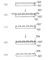
次に、スリット等の遮光パターンを作製する方法について図50を参照しつつ説明する。図50に示すように、透明な基板521上に、フォトレジスト522を塗布する(A)。次に、フォトレジスト522上に、あらかじめ電子ビーム露光等で作製しておいた所定のパターンを有するマスク523を密着させ又は接近させる(B)。さらに、レジストが反応しうる波長域の光を照射することにより、露出したレジストのみを可溶又は不溶にした後、マスク523を外す。基板521をレジスト溶剤に浸すと、基板521上にレジストによるマスクパターン522’が転写される(C)。マスクパターン522’が転写された基板521を蒸着装置(図示せず)に装着し、クロム等の金属524を蒸着する(D)。その後、蒸着装置から基板521を取り出し、アセトン等の有機溶剤で、基板521上に残ったフォトレジスト522’を除去する(E)。これら一連の作業の結果、基板521上にスリット等の遮光パターン525が形成される。
【0006】
以上のように、基板521上にスリット等の遮光パターン525を作製するには多くの工程が必要である。また、マスク523と基板521との位置合せも容易でない。そのため、周知のように、移動板503及び固定板506上にスリット等のパターンを形成するためのコストが高くなってしまう。そこで、インクリメンタル型光学式エンコーダにおいては、移動板503及び固定板506のA/B相信号領域(回折格子504及び507)に位相型光学素子を用いることによってコストを低減する方式が検討されている。
【0007】
位相型光学素子は、基板表面に凹凸形状を設けることにより作成することができる。その製造工程を図51に示す。所定の形状を有する金型531に、加熱等により流動性を持たせたアクリルやポリカーボネート等の透明樹脂532を流し込み、固化させる。得られた位相型光学素子には金型の形状が転写されている。この方法によれば、基板表面にスリット等の遮光パターンを作製する方法と比較して、基板とパターンとの位置合せの必要がなく、また、フォトレジストの塗布、紫外線照射、現象、金属膜の蒸着及び洗浄等の工程が不要である。
【0008】
A/B相信号領域を位相光学素子の一つである位相型回折格子とした一例として、例えばJPA6−042981に示された従来のインクリメンタル型エンコーダが知られている。その構成を図52に示す。図52において、光源501は半導体レーザ又は比較的可干渉性の高い発光ダイオードである。光源501から出射された光は、コリメータレンズ502により平行光化され、移動板503に入射する。移動板503は、主として±1次回折光を発生する位相型回折格子534を有し、かつ、前記平行光の光軸に対して略垂直に配置され、光軸と平行な回転中心512の周りに回転可能である。固定板506は、移動板503上の位相型回折格子534と等しい格子ピッチPを有する位相型回折格子537を有し、光軸に対して略垂直に配置されている。受光部510は受光部であり、位相型回折格子534と537の相対位置関係により形成される光を受光する。 光源501から出射された光は、コリメータレンズ502によって平行光にされた後、移動板503に対して略垂直に入射される。移動板503に入射した光は、移動板503上の位相型回折格子534により+1次回折光と−1次回折光に回折される。これらの光は固定板506上の位相型回折格子537に入射し、それぞれ+1次回折光と−1次回折光に回折される。位相型回折格子534と537の格子ピッチはともにPで等しいので、位相型回折格子534と537の回折角度は等しい。そのため、位相型回折格子534で−1次に回折し、位相型回折格子537で+1次に回折した光((−1、+1)次回折光)と、位相型回折格子534で+1次に回折し、位相型回折格子537で−1次に回折した光((+1、−1)次回折光)は、互いに光路が等しくなって干渉し、光の強弱が発生する。干渉条件は、移動板503の移動量δによるため、移動板503の移動量δによって光の強弱が変化する。すなわち、移動板503の移動量δにより、受光部510の受光光量が変化するので、移動板503の移動量が検出できる。
【0009】
一方、上記A/B相信号領域と同様に、Z相信号領域についても、スリットに代えて表面の凹凸形状にする方法が模索されている。例えば、図53に示すように、移動板503上に集光レンズ541を設け、その集光スポットを受光部511で受光することにより移動板503の移動基準点を検出する。この場合、Z相検出精度は集光スポットの大きさと受光部511の大きさによりほぼ決定され、集光スポットと受光部が小さいほど、高い検出精度を実現することができる。
(第2の従来例)
図49に示したインクリメンタル型光学式エンコーダは、Z相信号を基準としてA/B相信号の分だけ移動したとして、移動板503の位置検出を行う。従って、電源投入時の位置検出は不可能であり、基準位置の検出が必要不可欠となる。これに対し、スリットのパターンの違いにより、いつでも、どこの位置でも現在位置が検出できる、アブソリュート型光学式エンコーダが知られている。
【0010】
アブソリュート型光学式エンコーダの構成及び動作を説明する。図55に示すように、従来のアブソリュート型光学式エンコーダは、光源601と、光源601から出射される光を平行光にするためのコリメータレンズ602と、軸612を中心として回転し、略等ピッチのスリット604を円周状に配置したスリットトラックを複数個有する移動板603と、移動板603に対向するように配置され、回転板603上の複数スリットトラック604に対応した複数のスリット607を有する固定板606と、複数のスリット607に対応した複数の受光部610を有する受光器609等で構成されている。回転板603の各スリットトラックでは、互いにスリット604のピッチが異なるよう設置されている。各受光部610は移動板603のスリット604及び固体板606のスリット607を通った透過光を検出する。受光部610による検出信号のパターンにより、回転板603の絶対位置を検出することができる。
(第3の従来例)
従来より、物体に光を照射し、その像をテレビカメラ上に投影し、リニアアレイセンサの出力信号を2値化して位置を検出したり、あるいは移動する物体(以下移動体と記す)にスリットを設け、このスリットを通して光源からの出射光を受光部に入射させ、受光部の出力信号を2値化して移動体の移動基準点を検出することにより、物体の位置を非接触で検出することが広く行われている。例えば、JPA2−44202に示された従来の位置検出方法ついて、図56を参照しつつ説明する。
【0011】
図56は第3の従来例である位置検出装置の平面図を示す。図56において、701は光源、702は移動体であり、この移動体702上にスリット703が設けられている。705はスリット703を通過した光ビームであり、704は受光部である。移動体702は、光源701と受光部704の間にあり、光源701と受光部704を結ぶ軸に対し垂直方向に移動する。移動体702の移動につれて、光ビーム705も移動する。AAは光源701から移動体702までの距離であり、Bは移動体702から受光部704までの距離である。また、Δは移動体702の移動量、δδは光ビーム705の移動量である。このとき、光ビーム705の移動量δδは、次の(1)式で表される。
【0012】
δδ=Δ・B/AA ・・・(1)
【0013】
【発明が解決しようとする課題】
上記第1の従来例であるインクリメンタル型エンコーダにおいて、Z相信号領域について、スリットに代えて表面の凹凸形状にした場合、Z相検出精度を高めることが困難であるという問題を有する。集光スポット径の大きさは、幾何光学では光源501の大きさとコリメータレンズ502の焦点距離等により決定される。図54に示すように、光源501の大きさをφs1、コリメータレンズ502の焦点距離をfs1、Z相信号領域に設けた集光レンズ541の焦点距離をfs2とすると、集光スポット551の径φs2は幾何光学のガウスの公式より、以下の(2)式で表される。
【0014】
φs2=φs1・fs2/fs1…(2)
従って、集光スポット551の径φs2を小さくするには、第1に光源501の大きさφs1を小さくするか、第2にコリメータレンズ502の焦点距離fs1を大きくするか、第3にZ相信号領域の集光レンズ541の焦点距離fs2を小さくする等の方法が考えられる。しかしながら、第1の光源501の大きさを小さくする場合、光源501の近傍にピンホール等の遮光部を設ければよいが、利用できる光量が小さくなるという問題がある。また、A/B相信号領域とZ相信号領域の大きさにより、必要な平行光の直径、すなわちコリメータレンズ502の径が決まるため、第2のコリメータレンズ502の焦点距離fs1を大きくする場合、光源501の光の利用効率が小さくなるという問題がある。さらに、A/B相信号領域の信号発生方法によっては、例えば固定板506からの不要な回折光を分離するために、固定板506と受光部511との距離を大きくする必要があり、Z相信号領域の集光レンズ541の焦点距離fs2をあまり小さくできない。あるいは、A/B相信号用の受光部510とZ相信号用の受光部511とを分離し、A/B相信号用の受光部510を固定板506から必要な距離だけ離した位置に設け、Z相信号用の受光部511をそれよりも近づけて設けることも考えられるが、構造が複雑になり、また組立ても精度を要求され、コストアップの要因となる。
【0015】
通常、光学式エンコーダの光源501として発光ダイオードを用いるが、発光ダイオードの発光径φs1は小さく見積もって100μmである。また、コリメータレンズ502の焦点距離は、製品の大きさや仕様等から5mm程度以上、さらに、移動板503と受光部511との距離を20mm程度以上にする必要がある。その結果、移動板503上に設けた集光レンズ541による光スポット径は、上記(2)式から、約400μmとなる。A/B相信号のピッチ(又は周期)10μmと比較して、Z相信号はかなり幅の広い信号となってしまう。Z相検出精度を高めるために、受光部511の大きさを光スポット径よりも小さくし、検出信号を二値化する際のしきい値を高く設定することも考えられる。しかしながら、電気ノイズの影響や光源501の発光強度の変動による影響を受けやすく、安定してZ相の検出を行うことができない。
【0016】
さらに、この方法では、移動板503の移動量を検出する信号であるA/B相信号とZ層信号との同期をとることが困難であるという問題がある。図53に示した方法では、A/B相信号は移動板503と固定板506との相対位置関係で決まる波形の信号となるが、Z相信号はその発生過程で固定板506を必要とせず、移動板503と受光部511との相対位置関係で決まる波形となる。従って、A/B相信号とZ相信号を同期させるためには、移動板503、固定板506及び受光部511の各素子の位置決めを高い精度で行わなければならない。さらに、これらの各素子の微少な位置ずれにより、A/B相信号とZ相信号とが同期しなくなる。
【0017】
また、第2の従来例であるアブソリュート型エンコーダでは、移動板603及び固定板606上にそれぞれ複数のスリットトラックが設けられ、各スリットトラックにおけるスリット604のピッチが異なる。そのため、第1の従来例であるインクリメンタル型エンコーダのように、基板表面に等ピッチの凹凸形状を設けた位相型光学素子を用いる方法をとるがことができず、図50に示したように、スリットを形成するために、透明基板上に金属等の薄膜を蒸着する方法をとる必要がある。そのため、製造コストの低減を計ることは困難である。
【0018】
第3の従来例である位置検出方法において、移動体702の移動基準点の検出精度を上げるためには、移動体702の移動量Δによる光ビーム705の移動量δδを大きくすればよい。具体的には、距離Bを大きくし、距離AAを小さくすればよい。しかし、距離Bを大きくすると同時に距離AAを小さくすると、受光部704上での光ビーム705の径が大きくなる。その結果、移動体702の移動基準点の検出精度を下げることになる。一方、光ビーム705の径を小さくするために、スリット703を小さくしすぎると、光の回折が生じ、受光部704上の光ビーム705の径は逆に大きくなってしまう。また、スリット703を小さくすると、受光部704上での光量が少なくなり、ノイズの影響を受けやすくなるので、移動基準点の検出精度を下げる結果となる。さらに、回折の影響を防ぐためにスリット703と受光部704の距離Bを小さくすることも考えられるが、この距離を短くすると、移動体702と受光部704が接触して、互いに損傷を受ける危険がある。
【0019】
本発明は上記従来例の問題点に鑑み、光学式エンコーダにおいて、Z相信号とA/B相信号とを同期させつつ、精度の高い移動基準点検出、すなわち精度の高いZ相信号検出を可能とすることを目的とする。また、移動体と受光部間の距離を十分に確保し、移動板と固定板の凹凸形状で信号を発生させることができる光学式エンコーダ及び位置(角度)検出方法を提供することを目的とする。さらに、移動板の絶対位置を、移動板と固定板の凹凸形状で生じる信号により検出する光学式エンコーダ及び位置検出方法を提供することを目的とする。
【0045】
【課題を解決するための手段】
前述した目的を達成するために、本発明の第1の光学式エンコーダは、光源と、前記光源から出射された光を平行光にするレンズと、集光素子及び第1のトラック群の各トラックの格子ピッチが全て異なる第1の位相型回折格子を有する移動板と、第2のトラック群の各トラックの格子ピッチが全て異なる第2の位相型回折格子を有する固定板と、前記第1の位相型回折格子と前記第2の位相型回折格子とにより生成される第1の光パターン及び前記集光素子により生成される第2の光パターンを検出する光検出器とを備え、前記集光素子の中心を通る前記移動板の中心からの直線において、前記直線上に位置する前記第1のトラック群の各トラックの格子形状は、全て凹形状か、全て凸形状か、のいずれかであり、前記第2のトラック群の各トラックは、対向する前記第1のトラック群の各トラックと同一の格子ピッチ及び同一の格子形状を有することを特徴とする。
【0046】
すなわち、本発明の第1の光学式エンコーダは、集光素子及び第1のトラック群の各トラックの格子ピッチが全て異なる第1の位相型回折格子を有する移動板の第1の位相型回折格子と固定板の第2の位相型回折格子とにより、各トラックごとに複数の周期信号を発生させ、複数の周期信号と集光素子による信号との論理積をとることにより、移動板の基準位置を特定する。
【0048】
上記第1の光学式エンコーダにおいて、前記第1及び第3の位相型回折格子の各トラックにおける周期信号をそれぞれSo、Si(i=1〜n、nは2以上の整数)として、各周期VSo、VSiが、前記(3)式の条件を満たし、前記移動基準点近傍において、SiのパルスがSi−1のパルスをただ1つだけ含むことが好ましい。
【0049】
また、前記移動基準点近傍において、前記移動板上の集光素子が作る集光スポットを受光することによって生じる信号のパルスが、Snのパルスをただ1つだけ含むことが好ましい。
【0050】
また、本発明の第2の光学式エンコーダは、光源と、前記光源から出射された光を平行光にするレンズと、第1のトラック群の各トラックの格子ピッチが全て異なる第1の位相型回折格子を有する移動板と、第2のトラック群の各トラックの格子ピッチが全て異なる第2の位相型回折格子を有する固定板と、前記第1の位相型回折格子と前記第2の位相型回折格子とにより生成される光パターンを検出する光検出器とを備え、格子ピッチが最大となるトラックの凸形状端部を通る前記移動板の中心からの直線において、前記直線上に位置する前記第1のトラック群の各トラックの格子形状は、全て凹形状か、全て凸形状か、のいずれかであり、前記第2のトラック群の各トラックは、対向する前記第1のトラック群の各トラックと同一の格子ピッチ及び同一の格子形状を有することを特徴とする。
【0051】
すなわち、本発明の第2の光学式エンコーダは、第1及び第2の位相型回折格子は、それぞれ格子ピッチの異なる複数のトラックを有し、格子ピッチが最大となるトラックの凸形状端部を通る前記移動板の中心からの直線において、前記直線上に位置する前記第1のトラック群の各トラックの格子形状は、全て凹形状か、全て凸形状か、のいずれかであり、前記第2のトラック群の各トラックは、対向する前記第1のトラック群の各トラックと同一の格子ピッチ及び同一の格子形状を有しているため、各トラックごとに発生される周期信号はそれぞれパターンが異なるように設定される。各瞬間ごとのパターンをあらかじめ記憶しておいたパターンと比較することにより、移動板が現在移動基準位置からどの位置にあるのかを絶対的に判断することができる。
【0053】
上記第2の光学式エンコーダにおいて、前記光検出器の複数の周期信号をそれぞれSo、Si(i=1〜n、nは2以上の整数)とし、各周期VSo、VSiが、前記(4)式の条件を満たすことが好ましい。
【0086】
【発明の実施の形態】
以下、本発明の実施の形態を図面に基づいて説明する。
(実施の形態1)
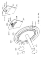
図1は本発明の実施の形態1を示す光学式エンコーダの基本構成図である。
【0087】
図1において、1は半導体レーザもしくは比較的可干渉性の高い発光ダイオードよりなる光源であり、この光源1より出射された光は、コリメータレンズ2により平行光とされ、移動板4へ入射される。
【0088】
この移動板4は、位相型回折格子7とフレネルゾーンプレート8を有し、コリメータレンズ2により形成された前記平行光の光軸に対して略垂直に配置され、この光軸と平行な回転中心を持つ回転軸3に直結され、この回転軸3を中心に回転移動する。この移動板4の回折格子7とフレネルゾーンプレート8を通過した透過光は固定板5へ入射される。
【0089】
固定板5は、移動板4の位相型回折格子7と等ピッチの位相型回折格子9とフレネルゾーンプレート10を有し、光軸に対して略垂直に配置されている。前記フレネルゾーンプレート8,10により形成される光のスポットは、受光器6の受光部11において受光される。
【0090】
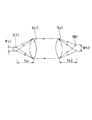
ここで、フレネルゾーンプレート8(10)の作用を図2によって説明する。図2はフレネルゾーンプレートの断面図およびフレネルゾーンプレートによる光の変調の様子を示したものである。
【0091】
フレネルゾーンプレート8は、ピッチの異なる位相型回折格子の集合体であり、そのピッチは外周ほど小さくなっており、フレネルゾーンプレート8へ入射した平行光は光軸上の距離fに光のスポットSをつくる。角度θは、スポットSを形成する光の集光角度である。回折格子のピッチが小さいほど回折角が大きいことは周知の通りである。
【0092】
フレネルゾーンプレート8では、外周ほどピッチを小さくすることで、回折光を光軸上の1点に集光させている。また、周知の通り、回折格子では+1次回折光の他に−1次回折光も生じるので、各回折格子からスポットSをつくるように回折する回折光を+1次回折光とすると、それぞれ−1次回折光も生じていることになる。そのため、フレネルゾーンプレート8では、角度θで集光スポットSをつくるとともに、角度θで拡散していく光を放射している。
【0093】
上記構成による作用を図3を参照しながら説明する。図3は図1のフレネルゾーンプレート8,10を透過する光の経路図である。
まず、光源1から出射された光は、コリメータレンズ2によって平行光にされた後、移動板4に対して略垂直に入射される。フレネルゾーンプレート8に入射した平行光は、距離fb1の位置に集光スポットS1を形成すると同時に、その集光角度と等しい角度で拡散する光を放射する。フレネルゾーンプレート8から拡散放射される光は、固定板5上のフレネルゾーンプレート10へ入射し、受光部11上で集光スポットS2を形成する。集光スポットS2が、フレネルゾーンプレート8,10の中心どうしを結んだ線上にできることは幾何光学で周知の通りである。フレネルゾーンプレート8,10の焦点距離をそれぞれfb1、fb2とし、移動板4と固定板5との距離をgとすると、固定板5から光スポットS2までの距離fcは、簡単な幾何学と光学におけるガウスの公式により、式(7)により与えられる。
【0094】
fc=(fb1+g)fb2/(fb1+g−fb2) ・・・(7)
この位置に受光部11を設置する。また移動板4の移動量をδb1とすると、集光スポットS2の移動量δcは、簡単な幾何光学の計算により、式(8)により与えられる。
【0095】
δc=δb1・fc/fb1 ・・・(8)
さらに、光源1の大きさをφaとし、コリメータレンズ2の焦点距離をfaとすると、集光スポットS2の径φcは、式(9)により与えられる。
【0096】

【0097】
【0098】
さらに、本実施の形態1によれば、Z相信号は移動板4と固定板5の相対位置関係によって決まる波形の信号となり、同じく移動板4と固定板5の相対位置関係で決まるA/B相信号と容易に同期をとることができる。
【0099】
一例としてfa=4.5mmのコリメータレンズ2を使い、fb1=0.6mm、fb2=0.7mm、g=0.3mmとすると、fc=3.15mmとなり、集光スポットS2の大きさは光源1の大きさの0.7倍に縮小され、集光スポットS2の移動量は移動板の移動量の5.25倍に拡大されることになる。このように、fb1、fb2、fa、gの各値を調整することでZ相検出精度を向上させることができる。
【0100】
また、受光部11の幅wと集光スポットS2の大きさとの関係を調整することにより、移動板4の原点付近での裕度を調整できる。さらに、フレネルゾーンプレート8,10は表面の凹凸形状で実現できるので、ポリカーボネートやアクリルなどの透明樹脂を基板材料に用いてスタンパ工法で作製できる。
【0101】
なお、本実施の形態1では、移動板4上のZ相信号領域のフレネルゾーンプレート8を拡散素子として、固定板5上のZ相信号領域のフレネルゾーンプレート10を集光素子として利用したが、移動板4上のZ相領域のフレネルゾーンプレート8を集光素子として、固定板5上のZ相信号領域のフレネルゾーンプレート10を拡散素子として利用しても同じ効果が得られる。
【0102】
なお、光源1として発光ダイオードなど発光部分の径が波長の数倍以上であるような、比較的大きい発光部分を有するものを用いる場合に、より有効な作用を得ることができる。
【0103】
なお、本実施の形態1の一例として、fa=4.5mm、fb1=0.6mm、fb2=0.7mm、g=0.3mmのものを使用したが、これ以外のものでも有効な作用が得られる。
【0104】
(実施の形態2)
図4は本発明の実施の形態2を示す光学式エンコーダの基本構成図である。なお、実施の形態1の図1の構成と同一の構成には同一の符号を付して説明を省略する。
【0105】
図4において、21はフレネルゾーンプレート8に代えて移動板4に設けられた凹レンズ、22はフレネルゾーンプレート10に代えて固定板5に設けられた凸レンズである。受光部11は、これらレンズ21,22により形成される光のスポットを受光する。
【0106】
上記構成による作用を図5を参照しながら説明する。
まず、光源1から出射された光は、コリメータレンズ2によって平行光にされた後、移動板4に対して略垂直に入射される。この移動板4の凹レンズ21に入射した平行光は、距離fb13の位置に集光スポットS3を形成するような集光角度で拡散する。凹レンズ21から拡散放射された光は、固定板5上の凸レンズ22へ入射し、受光部11上で光スポットS4を形成する。光スポットS4が、レンズ21,22の中心どうしを結んだ線上にできることは幾何光学で周知の通りである。
【0107】
レンズ21,22の焦点距離をそれぞれfb13、fb23とし、移動板4と固定板5との距離をg3とすると、固定板5から光スポットS4までの距離fc3は、簡単な幾何学と光学におけるガウスの公式により、式(11)により与えられる。
【0108】
δc3=δb13・fc3/fb13 ・・・(12)
さらに、光源1の大きさをφa3とし、コリメータレンズ2の焦点距離をfa3とすると、集光スポットS4の径φc3は、式(13)により与えられる。
【0109】
【0110】
【0111】
さらに、本実施の形態2によれば、Z相信号は移動板4と固定板5の相対位置関係によって決まる波形の信号となり、同じく移動板4と固定板5の相対位置関係で決まるA/B相信号と容易に同期をとることができる。
【0112】
一例としてfa3=4.5mmのコリメータレンズ2を使い、fb13=0.6mm、fb23=0.7mm、g3=0.3mmとすると、fc3=3.15mmとなり、集光スポットS4の大きさは光源1の大きさの0.7倍に縮小され、集光スポットS4の移動量は移動板4の移動量の5.25倍に拡大されることになる。このように、fb13、fb23、fa3、g3の各値を調整することでZ相検出精度を向上させることができる。
【0113】
また、受光部11の巾w3と集光スポットS4の大きさとの関係を調整することにより、移動板4の原点付近での裕度を調整できる。さらに、レンズ21,22は表面の凹凸形状で実現できるので、ポリカーボネートやアクリルなどの透明樹脂を基板材料に用いてスタンパ工法で作製できる。
【0114】
なお、本実施の形態2では、移動板4上のZ相信号領域の光学素子として凹レンズ21を、固定板5上のZ相信号領域の光学素子として凸レンズ22を利用したが、移動板4上のZ相領域の光学素子として凸レンズを、固定板5上のZ相信号領域の光学素子として凹レンズを利用しても同じ効果が得られる。
【0115】
なお、光源として発光ダイオードなど発光部分の径が波長の数倍以上であるような、比較的大きい発光部分を有するものを用いる場合に、より有効な作用を得ることができる。
【0116】
なお、本実施の形態2の一例として、fa3=4.5mm、fb13=0.6mm、fb23=0.7mm、g3=0.3mmのものを使用したが、これ以外のものでも有効な作用が得られる。
【0117】
(実施の形態3)
図6は本発明の実施の形態3を示す光学式エンコーダの基本構成図である。なお、実施の形態1の図1の構成と同一の構成には同一の符号を付して説明を省略する。
【0118】
図6において、31は、ハーフミラーであり、コリメータレンズ2によって平行光とされた光の光軸に沿って、コリメータレンズ2と移動板4間に配置され、光源1から出射された光がフレネルゾーンプレート8,10によって形成される光のスポットを、上方に設けた受光器6の受光部32に導く。受光部32により、光のスポットが受光される。なお、フレネルゾーンプレート10は反射型としている。
【0119】
上記構成による作用を図7を参照しながら説明する。
まず、光源1から出射された光は、コリメータレンズ2によって平行光にされた後、移動板4に対して略垂直に入射される。移動板4のフレネルゾーンプレート8に入射した平行光は、焦点距離fb12の位置に集光スポットS5を形成すると同時に、その集光角度と等しい角度で拡散する。フレネルゾーンプレート8から拡散放射される光は、固定板5の反射型フレネルゾーンプレート10へ入射し、集光されながら反射する。この光が再び移動板4上のフレネルゾーンプレート8へ入射することにより、光のスポットS6を生じる。この光のスポットS6は、ハーフミラー31により光源1からの光の光軸外へ曲げられ、受光部32に入射する。
【0120】
フレネルゾーンプレート8,10の焦点距離をそれぞれfb12、fb22とし、移動板4と固定板5の距離をg2とすると、フレネルゾーンプレート8によって拡散されフレネルゾーンプレート10で反射集光されるときの、フレネルゾーンプレート10から集光点までの距離fc2は、幾何光学のガウスの公式から、式(15)により与えられる。
【0121】
【0122】
【0123】
δd2=δb12・fd2/fb12 ・・・(17)
また集光スポットS6の大きさ(径)φd2は光源の大きさφa2とコリメータレンズ2の焦点距離fa2により、式(18)により与えられる。
【0124】
φd2=φa2・fd2/fa2 ・・・(18)
よって、フレネルゾーンプレート8の焦点距離fb12、フレネルゾーンプレート10の焦点距離fb22、コリメータレンズ2の焦点距離fa2、移動板4と固定板5の距離g2の値を調整することにより、集光スポットS6の大きさ(径)φd2と、光スポットS6の移動量δd2を調整することができ、集光スポットS6の大きさφd2を小さく、光スポットS6の移動量δd2を大きくすることによって、移動板4の移動基準点の検出精度を向上させることができる。
【0125】
さらに、本実施の形態3によれば、Z相信号は移動板4と固定板5の相対位置関係によって決まる波形の信号となり、同じく移動板4と固定板5の相対位置関係で決まるA/B相信号と容易に同期をとることができる。また、フレネルゾーンプレート8,10は表面の凹凸形状で実現できるので、ポリカーボネートやアクリルなどの透明樹脂を基板材料に用いてスタンパ工法で作製できる。
一例としてfa2=4.5mmのコリメータレンズ2を使い、fb12=1mm、fb22=5mm、g2=0.3mmとすると、fd2=2.23mmとなり、集光スポットS6の大きさは光源1の大きさの0.5倍に縮小され、集光スポットS6の移動量は移動板4の移動量の2.23倍に拡大されることになる。このように、fb12、fb22、fa2、g2の各値を調整することでZ相検出精度を向上させることができる。
【0126】
また、受光部32の巾w2と光スポットS6の大きさとの関係を調整することにより、移動板4の原点付近での裕度を調整できる。
なお、本実施の形態3では移動板4上のZ相信号領域のフレネルゾーンプレート8を、光源1からの光が入射するときに拡散素子として、固定板5から光が再入射するときに集光素子として、また固定板5上のZ相信号領域のフレネルゾーンプレート10を集光素子として利用したが、移動板4上のZ相領域のフレネルゾーンプレート8と固定板5上のZ相信号領域のフレネルゾーンプレート10を、拡散素子として使うか集光素子として使うかの組み合わせはその他も可能であり、また、フレネルゾーンプレート8,10を凹レンズあるいは凸レンズに代えても、本実施の形態3と同じ効果が得られる。
【0127】
なお、光源1として発光ダイオードなど発光部分の径が波長の数倍以上であるような、比較的大きい発光部分を有するものを用いる場合に、より有効な作用を得ることができる。
【0128】
なお、本実施の形態3の一例として、fa2=4.5mm、fb12=1mm、fb22=5mm、g2=0.3mmのものを使用したが、これ以外のものでも有効な作用が得られる。
【0129】
(実施の形態4)
図8は本発明の実施の形態4を示す光学式エンコーダの基本構成図である。なお、実施の形態1の図1の構成と同一の構成には同一の符号を付して説明を省略する。
【0130】
図8において、41はフレネルゾーンプレート8に代えて移動板4に設けられた、表面の微細な凹凸形状からなる光散乱源、42はフレネルゾーンプレート10に代えて固定板5に設けられた凸レンズである。受光部11は、光源1から出射された光が光散乱源41に入射することにより発生する散乱光を凸レンズ42で集光して形成した光のスポットを受光する。
【0131】
上記構成による作用を図9を参照しながら説明する。
まず、光源1から出射された光は、コリメータレンズ2によって平行光にされた後、移動板4に対して略垂直に入射される。移動板4の光散乱源41へ入射した平行光は、そこから散乱光を出射する。光散乱源41から出射される散乱光は、固定板5上の凸レンズ42へ入射し、受光部11上で光スポットS7を形成する。この光スポットS7が、光散乱源41と凸レンズ42の中心を結んだ線上にできることは幾何光学で周知の通りである。
【0132】
凸レンズ42の焦点距離をfb24とし、移動板4と固定板5との距離をg4とすると、固定板5から光スポットS7までの距離fc4は、簡単な幾何光学と、光学におけるガウスの公式により式(19)により与えられる。
【0133】
fc4=g4・fb24/(g4−fb24) ・・・(19)
この位置に受光部11を設置する。また移動板4の移動量をδb14とすると、光スポットS7の移動量δc4は、簡単な幾何光学の計算により式(20)により与えられる。
【0134】
δc4=δb14・fc4/g4 ・・・(20)
また光散乱源41の大きさをφb4とすると、光スポットS7の径φc4は式(21)により与えられる。
【0135】
φc4=φb4・fc4/g4 ・・・(21)
これらにより、光スポットS7の大きさ(径)φc4は式(22)に示すように、光源1の大きさφa4のE倍になり、光スポットS7の移動量δc4は、移動板4の移動量δb14のF倍となる。
【0136】
E=φb4・fc4/(g4・φa4)
F=fc4/g4 ・・・(22)
よって、光散乱源41の大きさφb4、凸レンズ42の焦点距離fb24、移動板4と固定板5との距離g4の値を調整することにより、光スポットS7の大きさ(径)φc4と、光スポットS7の移動量δc4を調整することができ、光スポットS7の大きさφc4を小さく、光スポットS7の移動量δc4を大きくすることによって、移動板4の移動基準点の検出精度を向上させることができる。
【0137】
さらに、本実施の形態4によれば、Z相信号は移動板4と固定板5の相対位置関係によって決まる波形の信号となり、同じく移動板4と固定板5の相対位置関係で決まるA/B相信号と容易に同期をとることができる。また、光散乱源41と凸レンズ42、受光部11を、コリメータレンズ2により形成される平行光の光軸上からはずして、光散乱源41からの光が受光部11上に光スポットS7を形成しないときに、光源1からの光が受光部11に入射しないようにすることで、Z相検出感度を高めることができる。
【0138】
一例として、φa4=200μmの光源1を使い、fb24=0.2mm、g4=0.3mm、φb4=50μmとすると、E=0.5、F=2となり、光スポットS7の大きさは光源1の大きさの0.5倍に縮小され、光スポットS7の移動量は移動板4の移動量の2倍に拡大されることになる。このように光散乱源41の大きさφb4、凸レンズ42の焦点距離fb24、移動板4と固定板5との距離g4の各値を調整することにより、Z相検出精度を向上させることができる。
【0139】
また、凸レンズ42は表面の凹凸形状で、光散乱源41は表面の微細な凹凸形状で実現できるので、ポリカーボネートやアクリルなどの透明樹脂を基板材料に用いてスタンパ工法で作製できる。
【0140】
なお、本実施の形態4において固定板5上の集光素子として凸レンズ42を用いたが、フレネルゾーンプレートを用いてもよいし、反射型の集光素子を用いてもよい。
【0141】
なお、本実施の形態4の一例として、fb24=0.2mm、g4=0.3mm、φb4=50μmのものを使用したが、これ以外のものでも有効な作用が得られる。
【0142】
(実施の形態5)
図10は本発明の実施の形態5を示す光学式エンコーダの基本構成図である。なお、実施の形態1の図1の構成と同一の構成には同一の符号を付して説明を省略する。
【0143】
図10において、51はフレネルゾーンプレート8に代えて移動板4に設けられた、表面切欠き形状からなる反射面、52はフレネルゾーンプレート10に代えて固定板5に設けられた凸レンズである。受光部11は、光源1から出射された光が反射面51に入射することにより発生する、コリメータレンズ2から出射される光の光軸外へ進む光を凸レンズ52で集光して形成した光のスポットS8を受光する。
【0144】
上記構成による作用を図11を参照しながら説明する。
まず、光源1から出射された光は、コリメータレンズ2によって平行光にされた後、移動板4に対して略垂直に入射される。移動板4に入射した光は、反射面51で平行光の光軸外へ反射される。その反射光は、固定板5上に設置される凸レンズ52へ入射し、受光部11上で光スポットS8を形成する。この光スポットS8が、反射面51と凸レンズ52の中心を結んだ線上にできることは幾何光学で周知の通りである。
【0145】
凸レンズ52の焦点距離をfb25とし、移動板4と固定板5との距離をg5とすると、固定板5から光スポットS8までの距離fc5は、簡単な幾何光学と、光学におけるガウスの公式により式(23)により与えられる。
【0146】
fc5=g5・fb25/(g5−fb25) ・・・(23)
この位置に受光部11を設置する。また移動板4の移動量をδb15とすると、光スポットS8の移動量δc5は、簡単な幾何光学の計算により式(24)により与えられる。
【0147】
δc5=δb15・fc5/g5 ・・・(24)
また反射面51の大きさをφb5とすると、光スポットS8の径φc5は式(25)により与えられる。
【0148】
φc5=φb5・fc5/g5 ・・・(25)
これらにより、光スポットS8の大きさ(径)φc5は式(26)に示すように、光源1の大きさφa5のG倍になり、光スポットS8の移動量δc5は、移動板4の移動量δb15のH倍となる。
【0149】
G=φb5・fc5/(g5・φa5)
H=fc5/g5 ・・・(26)
よって、反射面51の大きさφb5、凸レンズ52の焦点距離fb25、移動板4と固定板5との距離g5の値を調整することにより、光スポットS8の大きさ(径)φc5と、光スポットS8の移動量δc5を調整することができ、光スポットS8の大きさφc5を小さく、光スポットS8の移動量δc5を大きくすることによって、移動板4の移動基準点の検出精度を向上させることができる。
【0150】
さらに反射面51の大きさを小さくし、受光部11の大きさを小さくすることによりZ相検出精度を高めることができる。また反射面51の角度を、入射した平行光が全反射するようにしてやれば、光の利用効率を高めることができる。さらに基板に屈折率1.5の材料を使用する場合、固定板5の周りの雰囲気が空気であれば全反射角度は44.4度となるため、これ以上の角度で平行光が反射面に入射するようにし、その全反射光を凸レンズ52で集光して受光部11で受光すればよい。
【0151】
さらに、本実施の形態5によれば、Z相信号は移動板4と固定板5の相対位置関係によって決まる波形の信号となり、同じく移動板4と固定板5の相対位置関係で決まるA/B相信号と容易に同期をとることができる。
【0152】
一例として、φa5=200μmの光源1を使い、fb25=0.2mm、g5=0.3mm、φb5=50μmとすると、G=0.5、H=2となり、光スポットS8の大きさは光源1の大きさの0.5倍に縮小され、光スポットS8の移動量は移動板4の移動量の2倍に拡大されることになる。このように反射面51の大きさφb5、凸レンズ52の焦点距離fb25、移動板4と固定板5との距離g5の各値を調整することにより、Z相検出精度を向上させることができる。
【0153】
また、凸レンズ52および反射面51は表面の凹凸形状で実現できるので、ポリカーボネートやアクリルなどの透明樹脂を基板材料に用いてスタンパ工法で作製できる。
【0154】
なお、本実施の形態5において集光素子として凸レンズ52を用いたが、フレネルゾーンプレートを用いてもよいし、反射型の集光素子を用いて同じ効果が得られる。
【0155】
なお、本実施の形態5の一例として、fb25=0.2mm、g5=0.3mm、φb5=50μmのものを使用したが、これ以外のものでも有効な作用が得られる。
(実施の形態6)
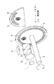
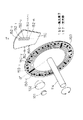
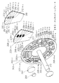
本発明の光学式エンコーダ及び位置検出方法に関する実施の形態6について、図12〜図16を参照しつつ説明する。図12は本発明の光学式エンコーダの実施の形態6の基本構成を示す斜視図である。図12に示す光学式エンコーダは、半導体レーザ又は比較的可干渉性の高い発光ダイオード等の光源101と、光源101より出射された光を平行光にするコリメータレンズ102と、平行光の光軸に対して略垂直に配置され、光軸と平行な回転軸114を中心に回転可能な移動板103と、光軸に対して略垂直に配置された固定板107と、複数の受光部を有する受光器110等で構成されている。
【0156】
円盤状の移動板103は、全周にわたって環状に配置された位相型回折格子104と、同心円状に配置された複数の円弧状の位相型回折格子105−1、105−2、・・・105−n(但し、nは2以上の整数)(以下、105−i(i=1〜n)と一般化する。他も同様。)と、フレネルゾーンプレート106を有する。略扇形の固定板107は、移動板103の各位相型回折格子104、105−i(i=1〜n)にそれぞれ対応し、等しいピッチを有する略円弧状に形成された位相型回折格子108及び109−i(i=1〜n)を有する。受光器110の受光部111は、移動板103のフレネルゾーンプレート106により形成される光スポットを受光する。また、受光部112は、移動板103の位相型回折格子104と固定板107の位相型回折格子108により形成される光を受光する。受光部113−i(i=1〜n)は、それぞれ移動板103の位相型回折格子105−iと固定板107の位相型回折格子109−iにより形成される光を受光する。
【0157】
上記各位相型回折格子の断面形状を図13に示す。図13において、図13Aは位相型回折格子104及び108の断面形状であり、格子ピッチP0 を有する。図13Bは位相型回折格子105−1及び109−1の断面形状であり、格子ピッチP1 を有する。図13Cは位相型回折格子105−2及び109−2の断面形状であり、格子ピッチP2 を有する。同様にして、図13Dは位相型回折格子105−n及び109−nの断面形状であり、格子ピッチPnを有する。格子ピッチP0、P1・・・Pnは順にピッチ間隔が広くなっていることがわかる。
【0158】
位相型回折格子104及び108は、移動板103の移動量検出(A/B相)信号用であり、位相型回折格子104は、移動板103上の回転軸114を中心とする円の全周に設けられている。図52に示す従来例と同様に、移動板103上の位相型回折格子104と、対応する固定板107上の位相型回折格子108により、光の強弱変化が生じる。移動板103に入射した光は、移動板103上の位相型回折格子104により+1次回折光と−1次回折光に回折される。これらの回折光は固定板107上の位相型回折格子108に入射し、それぞれ+1次回折光と−1次回折光に回折される。移動板103上の位相型回折格子104と、対応する固定板107上の位相型回折格子108の格子ピッチは共にPOであり、等しい回折角度を有する。そのため、移動板103上の位相型回折格子104により−1次に回折され、固定板107上の位相型回折格子108により+1次に回折された光((−1、+1)次回折光)と、移動板103上の位相型回折格子104により+1次に回折され、固定板107上の位相型回折格子108により−1次に回折された光((+1、−1)次回折光)は、互いに光路が等しくなって干渉し、光の強弱が発生する。干渉条件は、移動板103の移動量δによるので、移動板103の移動量δによって受光部112の受光量が変化し、移動板103の移動量が検出できる。以上を数式で表すと以下のようになる。
【0159】
【0160】
ここで、図12及び図13中における0°線はZ相信号を発生させたい位置であり、移動板103及び固定板107にそれぞれに想定されている。図13に示すように、0°線が各位相型回折格子104、105−i(i=1〜n)、108、109−i(i=1〜n)の凸部上を通るように形成されている。位相型回折格子104及び108の0°線近傍の拡大図を図14Aに示す。また、位相型回折格子105−1及び109−1の0°線近傍の拡大図を図14Bに示す。図14A及びBにおいて、それぞれ紙面右側を正方向、左側を負方向とする。
【0161】
図14Aに示す位相型回折格子104及び108において、”a”は0°線から0°線が通る格子凸部141の正方向の端部141aまでの距離(角度)を表す。また、0°線から格子凸部141の正方向に隣接する格子凸部142の端部142aまでの距離(角度)は”a+P0/2”で表される。さらに、0°線から格子凸部141の負方向の端部141bまでの距離(角度)は”P0/2−a”で表され、0°線から格子凸部141と負方向に隣接する格子凸部143の端部143aまでの距離(角度)は”P0−a”で表される。
図14Bにおいて、”b”は0°線から位相型回折格子105−1及び109−1の格子凸部151の正方向の端部151aまでの距離(角度)を表す。位相型回折格子105−1及び109−1において、0°線から格子凸部151の負方向の端部151bまでの距離(角度)は”P1 /2−b”で表される。
【0162】
位相型回折格子104及び108と105−1及び109−1との位置関係について、位相型回折格子105−1及び109−1の0°線が通る格子凸部151が、位相型回折格子104及び108の0°線が通る格子凸部141をただ1つだけ含む条件、すなわち、以下の(30)式及び(31)式が成り立つ。
【0163】
|a|≦|b|≦|a+P0/2| ・・・(30)
|P0/2−a|≦|P1/2−b|≦|P0−a| ・・・(31)
同様に、格子105−1及び109−1と105−2及び109−2との関係についても、位相型回折格子105−2及び109−2の0°線が通る格子凸部が、位相型回折格子105−1及び109−1の0°線が通る格子凸部をただ1つだけ含む条件が成り立つ。すなわち、0°線から0°線が通る格子105−2及び109−2の格子凸部の正方向の端部までの距離(角度)を”c”(図示せず)とし、0°線から0°線が通る格子凸部の負方向の端部までの距離(角度)を”P2/2−c”とし、位相型回折格子105−1及び109−1における0°線から0°線が通る格子凸部と正方向に隣接する格子凸部に始まる端部までの距離(角度)を”b+P1/2”とし、0°線から0°線が通る格子凸部の負方向の端部までの距離(角度)を”P1 −b”として、以下の(32)式及び(33)式が成り立つ。
【0164】
|b|≦|c|≦|b+P1/2| ・・・(32)
|P1/2−b|≦P2/2−c|≦|P1−b| ・・・(33)
以下、位相型回折格子105−2及び109−2と105−3及び109−3との関係、・・・位相型回折格子105−(n−1)及び109−(n−1)と105−n及び109−nとの関係についても同様である。
【0165】
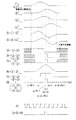
図12に示す移動板103のフレネルゾーンプレート106は受光器110上に焦点を結び、光スポットを作る。移動板103の回転に伴い、受光器110上の光スポットも移動するが、光スポットが受光部111で受光されることにより、1回転で1パルス分の信号が生成される。これらの位相型回折格子104、105−i(i=1〜n)及びフレネルゾーンプレート106により、移動板103の回転移動にともない生成される各受光部111,112,113−i(i=1〜n)の出力信号を2値化したものを示したものを図15に示す。図15において、Aは受光部112の受光信号を2値化したものであり、周期はP0 /2である。Z1、Z2、・・・Znは、それぞれ受光部113−1、113−2、・・・113−nの受光信号を2値化したものであり、それぞれ周期はP1 /2、P2 /2・・・Pn/2である。
【0166】
図13及び図14に示したように、各位相型回折格子は、位相型回折格子105−1及び109−1の0°線が通る格子凸部が位相型回折格子104及び108の0°線が通る格子凸部をただ1つだけ含み、位相型回折格子105−2及び109−2の0°線が通る格子凸部が位相型回折格子105−1及び109−1の0°線が通る格子凸部をただ1つだけ含み、・・・という関係に配置されている。そのため、出力信号も同様に、Z1の0°線が通るパルスがAの0°線が通るパルスをただ1つだけ含み、Z2の0°線が通るパルスがZ1の0°線が通るパルスをただ1つだけ含み、・・・Znの0°線が通るパルスがZn−1の0°線が通るパルスをただ1つだけ含むという関係になる。また、Zdは、受光部111の受光信号を2値化したものであり、Wzdの幅を有し、Znの0°線が通るパルスをただ1つだけ含む。
【0167】
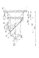
図16は、図15に示す各信号の0点近傍における拡大図であり、各信号間の関係を表す。0点は、移動板103の0°線が固定板107の0°線に到達した瞬間を意味する。図中、紙面右側を正方向、左側を負方向とする。”α”は、信号Aにおける0点から0点を含むパルス161の正方向における終端161aまでの距離(角度)を表す。”β1 ”は、信号Z1 における0点から0点を含むパルス171の正方向における終端171aまでの距離(角度)を表す。このとき、信号Aにおいて、0点からパルス161と正方向に隣接するパルス162が始まる端部162aまでの距離(角度)は”α+P0/4”で表され、0点からパルス161負方向における終端161bまでの距離(角度)は”P0/4−α”で表され、0点からパルス161と負方向に隣接するパルス163が始まる端部163aまでの距離(角度)は”P0/2−α”で表される。また、信号Z1 において、0点からパルス171の負方向における終端171bまでの距離(角度)は”P1/4−β1”で表される。
【0168】
信号AとZ1 との関係は、Z1の0点を含むパルス171が、Aの0点を含むパルス161をただ1つだけ含む条件、すなわち、以下の(34)式及び(35)式が成り立つ。
【0169】
|α|≦|β1|≦|α+P0/4| ・・・(34)
|P0/4−α|≦|P1/4−β1|≦|P0/2−α|・・・(35)
同様に、信号Z1とZ2の関係についても、信号Z2の0点を含むパルス181が、信号Z1の0点を含むパルス171をただ1つだけ含むような条件が成り立つ。すなわち、信号Z2において、0点からパルス181の正方向における終端181aまでの距離(角度)を”β2”とし、0点からパルス181の負方向における終端181bまでの距離(角度)を”P2/4−β2”とし、信号Z1における、0点からパルス171と正方向に隣接するパルス172が始まる端部172aまでの距離(角度)を”β1+P1/4”とし、0点からパルス171と負方向に隣接するパルス173が始まる端部173aまでの距離(角度)”P1/2−β1”として、以下の(36)式及び(37)式が成り立つ。
【0170】
【0171】
【0172】
従来例の説明において述べたように、A、Z1・・・等の等ピッチの位相型回折格子を相対変化させることにより、発生する信号の周期を小さくすることができる。これに対し、Zd のような移動板103上に設けたフレネルゾーンプレート106等の集光素子によるスポット光検出により発生される信号の幅は、狭くすることができない。そのため、単にA/B相信号である信号Aと、Z相信号発生用の信号である信号Zdを発生させて、それらの理論和をとるだけでは、A/B相1パルスと同期したZ相信号は生成できない。しかしながら、本発明のように、A、Z1、Z2・・・ZnとZdの論理積をとり、これをZ相信号とすることにより、A/B相1パルスと同期したZ相信号を生成することができる。
【0173】
また、単にA/B相信号である信号Aと、Z相信号発生用の信号である信号Zdを発生させ、Zdのパルスが発生した瞬間から、A/B相信号パルス1つ分を電気回路で抜き出し、これをZ相信号とする方法も可能である。しかしながら、Zdのパルスは、電気ノイズ、機械振動、その他の様々な要因のため、必ずしも一定のタイミングで発生するとは限らない。Zdの発生タイミングずれの許容値は、信号Aの凹部1つ分、すなわち、P0/4である。これに対し、A、Z1、Z2、・・・ZnとZdの論理積をとり、これをZ相信号とすれば、Zdの発生タイミングずれの許容値は、信号Znの凹部1つ分、すなわち、Pn/4である。上記(30)〜(33)式に示す条件等から、Pn/4≧P0/4が成り立つ。すなわち、本発明によれば、Zd の発生のタイミングのずれ許容値が大きくとることができ、電気ノイズ、機械振動等に強い光学式エンコーダを実現することができる。また、位相型回折格子104、105−i(i=1〜n)、108、109−i(i=1〜n)及びフレネルゾーンプレート106を基板表面の凹凸形状で実現することができるため、透過性を有する樹脂を用いて、スタンパ工法により作製することができる。
【0174】
なお、各位相型回折格子104、105−i(i=1〜n)、108、109−i(i=1〜n)の全てに関して0°線が格子凸部を通るようにしたが、0°線が格子凹部を通るように構成しても同様の効果が得られる。あるいは、各位相型回折格子104、105−i(i=1〜n)、108、109−i(i=1〜n)の全てに共通して、0°線が格子凸部又は格子凹部を通らなくてもよく、一部の位相型回折格子に関しては、0°線が格子凸部を通り、他の位相型回折格子に関しては、0°線が格子凹部を通るように0°線下に凸部と凹部を混合した配置であっても同様の効果が得られる。
【0175】
また、移動板103と固定板107に関して、0°線がともに各位相型回折格子の凸部又は凹部を通らなくてもよく、例えば移動板103では0°線が各位相型回折格子104、105−1・・・105−nの凸部を通り、固定板107では0°線が各位相型回折格子108、109−1・・・109−nの凹部を通るような構成であっても又はその逆の構成であってもよい。また、信号Z1の0°線が通るパルス171が、信号Aの0°線が通るパルス161をただ1つだけ含み、信号Z2の0°線が通るパルス181が信号Z1 のパルス171をただ1つだけ含み、・・・信号Zn の0°線が通るパルスが信号Zn−1の0°線が通るパルスをただ1つだけ含むという関係の出力信号、すなわち、(34)〜(39)式の条件を満たす出力信号が得られる位相型回折格子の配列であれば、上に示した格子配列でなくとも、同じ効果が得られる。また、移動板103上に設置する集光素子としてフレネルゾーンプレート106を用いたが、レンズを用いても同じ効果が得られる。
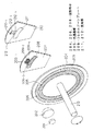
(実施の形態7)
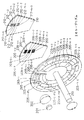
次に本発明の光学式エンコーダ及び位置検出方法に関する実施の形態7について、図17〜図19を参照しつつ説明する。図17は本発明の光学式エンコーダの実施の形態7の基本構成を示す斜視図である。図17に示す光学式エンコーダは、半導体レーザ又は比較的可干渉性の高い発光ダイオード等の光源101と、光源101より出射された光を平行光にするコリメータレンズ102と、平行光の光軸に対して略垂直に配置され、光軸と平行な回転軸114を中心に回転可能な移動板103と、光軸に対して略垂直に配置された固定板107と、複数の受光部を有する受光器110等で構成されている。
【0176】
円盤状の移動板103は、全周にわたって環状に想定された複数のトラック上に形成され、主として±1次回折光を発生する複数の位相型回折格子130−0、130−1、130−2、・・・130−(n−1)、130−n(nは2以上の整数)を有する。各トラック上の位相型回折格子130−i(i=0〜n)では、それぞれ格子ピッチが異なるが、1つのトラック上では格子ピッチは一定である。略扇型の固定板107は、移動板103上の位相型回折格子130−i(i=0〜n)に対応し、各格子ピッチと等しい格子ピッチを有する位相型回折格子131−i(i=0〜n)を有する。受光器110の各受光部132−i(i=0〜n)は、それぞれ移動板103の位相型回折格子130−iと131−i(i=0〜n)の相対位置関係により形成される光を受光する。
【0177】
上記本発明の実施の形態6と同様に、移動板103に入射した光は、移動板103上の位相型回折格子130−i(i=0〜n)により、+1次回折光と−1次回折光に回折され、それらの光は、それぞれ固定板107上の位相型回折格子131−i(i=0〜n)に入射し、+1次回折光と−1次回折光に回折される。移動板103上の位相型回折格子130−i(i=0〜n)と、対応する固定板107上の位相型回折格子131−i(i=0〜n)の格子ピッチはともに等しいので、等しい回折角度を有する。そのため、移動板103上の位相型回折格子130−i(i=0〜n)により−1次に回折され、固定板107上の位相型回折格子131−i(i=0〜n)により+1次に回折された光((−1、+1)次回折光)と、移動板103上の位相型回折格子130−i(i=0〜n)により+1次に回折され、固定板107上の位相型回折格子131−i(i=0〜n)により−1次に回折された光((+1、−1)次回折光)は、互いに光路が等しくなって干渉し、光の強弱が発生する。干渉条件は、移動板103の移動量δによるので、移動板103の移動量δによって受光部132−i(i=0〜n)の受光光量が変化し、移動板103の移動量が検出できる。
【0178】
このとき、各受光部132−i(i=0〜n)による検出信号は位相型回折格子の格子ピッチの1/2の周期を有する正弦波状信号となる。図17に示すように、移動板103の位相型回折格子130−i(i=0〜n)及び固定板107の位相型回折格子131−i(i=0〜n)では、それぞれトラックが異なるごとに格子ピッチがそれぞれ違うように設定されているので、これらの位相型回折格子により形成される干渉光強度変化の周期は、各トラックごとにそれぞれ異なる。すなわち、各受光部132−i(i=0〜n)の受光信号の周期がそれぞれ異なる。
【0179】
図18は、移動板103及び固定板107上の0°線近傍における位相型回折格子130−i(i=0〜n)及び131−i(i=0〜n)の断面形状を示したものである。各トラックにおける位相型回折格子130−i(i=0〜n)及び131−i(i=0〜n)は、それぞれP3−0、P3−1、・・・P3−(n−1)、P3−nの格子ピッチを有し、格子凸部の端部が、図17の移動板103及び固定板107にそれぞれ示した0°線上にある。各格子ピッチP3−0、P3−1、・・・?P3−(n−1)、P3−nは、以下に示す(40)式及び(41)式の関係にある。
【0180】
【0181】
このように、各受光部132−i(i=0〜n)のH、L信号の組み合わせは、移動板103の位置に依存する。移動板103が、ある位置にあるときの各トラックの2値化信号パターンが、移動板が他のいずれの位置にあるときの2値化信号パターンとも異なるように設定することにより、受光信号パターンから移動板の絶対的回転位置を検出することができる。移動板103の位置に特有の信号パターンが得られるので、移動板103の回転位置がどこであっても位置検出が可能な絶対位置検出型光学式エンコーダとなる。
【0182】
位相型回折格子は基板表面の凹凸形状により実現することができ、ポリカーポネートやアクリル等の透明樹脂を用いて、スタンパ工法により安価に作製することができる。なお、上記実施の形態7では、移動板103及び固定板107上の位相型回折格子130−i及び131−i(i=0〜n)を、図18に示すように、0°線の紙面右側に凸部を配置したが、紙面右側に凹部を配置しても同様の効果が得られる。また、位相型回折格子130−i及び131−i(i=0〜n)を、0°線にあわせて全て凸部としたが、凸部及び凹部の混合としても同様の効果が得られる。さらに、移動板103上の位相型回折格子130−i(i=0〜n)と固定板107上の位置型回折131−i(i=0〜n)の凹凸位置の配列を同じにしたが、これらの凹凸位置の配列が同じでなくても同様の効果が得られる。さらに、0°線上にあわせて位相型回折格子130−i及び131−i(i=0〜n)を配置したが、2値化した受光信号が、図19に示すような、複数の位相型回折格子のうち、最も格子ピッチの小さい位相型回折格子により得られる信号周期の整数倍の周期信号が発生できるような格子配置であれば、同様の効果が得られる。
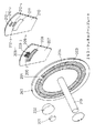
(実施の形態8)
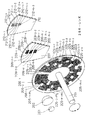
次に本発明の光学式エンコーダ及び位置検出方法に関する実施の形態8について、図20〜図23を参照しつつ説明する。図20は本発明の光学式エンコーダの実施の形態8の基本構成を示す斜視図である。図20に示す光学式エンコーダは、半導体レーザ又は比較的可干渉性の高い発光ダイオード等の光源101と、光源101より出射された光を平行光にするコリメータレンズ102と、平行光の光軸に対して略垂直に配置され、光軸と平行な回転軸114を中心に回転可能な移動板103と、光軸に対して略垂直に配置された固定板107と、複数の受光部を有する受光器110等で構成されている。
【0183】
円盤状の移動板103は、全周にわたって環状に配置された複数のトラックからなり、主として±1次回折光を発生する複数の位相型回折格子140−0、140−1、140−2、・・・140−(n−1)、140−n(nは2以上の整数)を有する。各トラック上の位相型回折格子140−i(i=0〜n)では、それぞれ格子が設けられている領域と格子が設けられていない領域のパターンが異なり、かつ各トラック上の格子ピッチも異なる。略扇型の固定板107は、移動板103上の各トラックで変調された光を選択的に透過させたための光透過部141及びその両側に設けられたフレネルゾーンプレート143を有する。受光器110の各受光部142−i(i=0〜n)は、それぞれ移動板3の位相型回折格子140−iと固定板107の光透過部141を通過した光を受光する。
【0184】
上記本発明の光学式エンコーダの実施の形態8の光路図を図21に示す。図21において、AとBとでは移動板103の位置が異なる。光源101から出射された光はコリメータレンズ102により平行光化され、移動板103に入射する。移動板103が図21Aに示す位置の場合、光は移動板103では変調されず、そのまま透過し、さらに固定板107の光透過部141を透過し、受光部142−i(i=0〜n)に入射する。移動板103が移動し、図21Bに示す位置の場合、光は移動板103上の位相型回折格子140−i(i=0〜n)により+1次回折光と−1次回折光に分離され、0次回折光、すなわち直進する光の強度はほぼ0となる。移動板103上の位相型回折格子140−i(i=0〜n)により±1次に回折された光は、固定板107上のフレネルゾーンプレート143により進路を曲げられ、受光部142−i(i=0〜n)には入射しないか、入射してもその光量は少ない。すなわち、移動板103の位置により、受光部142−i(i=0〜n)での受光量が変化する。
移動板103上の0°線近傍における、位相型回折格子140−0、140−1、・・・140−(n−1)、140−nの断面形状を図22に示す。各位相型回折格子140−i(i=0〜n)は、それぞれP4−0、P4−1、・・・P4−(n−1)、P4−n の格子ピッチを有する。また、各位相型回折格子140−i(i=0〜n)の格子の設けられている領域と格子が設けられていない領域の周期を、それぞれL4−0、L4−1、・・・L4−(n−1)、L4−nとする。また、各位相型回折格子140−i(i=0〜n)の格子が設けられている領域の端部は、図20の移動板103に示した0°線上にあるものとする。各位相型回折格子140−i(i=0〜n)の格子が設けられている領域と格子が設けられていない領域の周期L4−0、L4−1 、・・・L4−(n−1)、L4−n は、以下に示す(42)式及び(43)式に関係にある。
【0185】
【0186】
このように、各受光部142−i(i=0〜n)のH、L信号の組み合わせは、上記実施の形態7の場合と同様に、移動板103の位置に依存する。移動板103が、ある位置にあるときの各トラックの2値化信号パターンが、移動板が他のいずれの位置にあるときの2値化信号パターンとも異なるように設定することにより、受光信号パターンから移動板の絶対的回転位置を検出することができる。移動板3の位置に特有の信号パターンが得られるので、移動板103の回転位置がどこであっても位置検出が可能な絶対位置検出型光学式エンコーダとなる。
【0187】
位相型回折格子は基板表面の凹凸形状により実現することができ、ポリカーボネートやアクリル等の透明樹脂を用いて、スタンパ工法により安価に作製することができる。なお、上記実施の形態8では、移動板103上の位相型回折格子140−i(i=0〜n)を、図22に示すように、0°線の紙面右側に格子が設けられている領域を配置したが、紙面右側に格子が設けられていない領域を配置しても同様の効果が得られる。また、位相型回折格子140−i(i=0〜n)を、0°線にあわせて全て格子が設けられている領域としたが、格子が設けられている領域と格子が設けられていない領域とを混合して配置しても同様の効果が得られる。さらに、0°線上にあわせて位相型回折格子140−i(i=0〜n)の格子が設けられている領域を配置したが、2値化した受光信号が、図23に示すような、複数の位相型回折格子のうち、最も格子が設けられている領域と格子が設けられていない領域の周期の小さいトラックにより得られる信号周期の整数倍の周期信号が発生できるような格子配置であれば、同様の効果が得られる。(実施の形態9)
次に本発明の光学式エンコーダ及び位置検出方法に関する実施の形態9について、図24〜図27を参照しつつ説明する。図24は本発明の光学式エンコーダの実施の形態9の基本構成を示す斜視図である。図24に示す光学式エンコーダは、半導体レーザ又は比較的可干渉性の高い発光ダイオード等の光源101と、光源101より出射された光を平行光によるコリメータレンズ102と、平行光の光軸に対して略垂直に配置され、光軸と平行な回転軸114を中心に回転可能な移動板103と、複数の受光部を有する受光器110等で構成されている。
【0188】
円盤状の移動板103は、回転軸114の回転中心の周りに同心円的に想定された複数のトラック上に、それぞれ異なった一定の間隔(角度)で配置された、例えばフレネルゾーンプレート等の集光素子150−0、150−1、150−2、・・・150−(n−1)、150−nを有する。受光器110の各受光部152−i(i=0〜n)は、それぞれ集光素子150−i(i=0〜n)により形成されるスポット光を集光する。
【0189】
上記本発明の光学式エンコーダの実施の形態9の光路図を図25に示す。図25Aと図25Bとでは移動板103の位置が異なる。光源101から出射された光はコリメータレンズ102により平行光化され、移動板103に入射する。移動板103が(a)に示す位置の場合、入射光は移動板103上の集光素子150−i(i=0〜n)により集光され、受光部152−i(i=0〜n)に入射する。移動板103が移動し、図25Bに示す位置になった場合、入射光は移動板103を透過し、この場合も受光部152−i(i=0〜n)に入射する。しかし、受光部152−i(i=0〜n)に入射する光の強度は、図25Bに示すように平行光がそのまま移動板103を透過する場合よりも、図25Aに示すように集光素子150−i(i=0〜n)により集光される場合の方が大きいことは明らかである。従って、移動板103の位置により、受光部152−i(i=0〜n)の受光量が変化する。
【0190】
移動板103上の0°線近傍における集光素子150−i(i=0〜n)の断面を図26に示す。各トラックにおける集光素子150−i(i=0〜n)の間隔を、それぞれ、L5−0、L5−1、・・・L5−(n−1)、L5−nとして、以下の(44)式及び(45)式の関係にある。
【0191】
【0192】
このように、各受光部52−i(i=0〜n)のH、L信号の組み合わせは、実施の形態8の場合と同様に、移動板103の位置に依存する。移動板103が、ある位置にあるときの各トラックの2値化信号パターンが、移動板が他のいずれの位置にあるときの2値化信号パターンとも異なるように設定することにより、受光信号パターンから移動板の絶対的回転位置を検出することができる。移動板103の位置に特有の信号パターンが得られるので、移動板103の回転位置がどこであっても位置検出が可能な絶対位置検出型光学式エンコーダとなる。
【0193】
フレネルゾーンプレート等の集光素子は、基板表面の凹凸形状として実現できるので、ポリカーボネートやアクリル等の透明樹脂を用いて、スタンパ工法により安価に作製することができる。なお、上記実施の形態9では、移動板103の0°線上にあわせて集光素子を配置したが、2値化した受光信号が、図27に示すように、複数のトラック信号のうち、最も周期の小さいトラック信号の周期の整数倍の周期信号が発生できるような集光素子の配置であれば、同様の効果が得られる。また、移動板上の集光素子としてフレネルゾーンプレートの代わりに集光レンズを用いても同様の効果が得られる。
(実施の形態10)
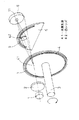
本発明の光学式エンコーダ及び位置検出方法に関する実施の形態10について、図28〜図31を参照しつつ説明する。図28は本発明の光学式エンコーダの実施の形態10の基本構成を示す斜視図である。図28に示す光学式エンコーダは、半導体レーザ又は比較的可干渉性の高い発光ダイオード等の光源201と、光源201より出射された光を平行光にするコリメータレンズ202と、平行光の光軸に対して略垂直に配置され、光軸と平行な回転軸213を中心に回転可能な移動板203と、光軸に対して略垂直に配置された固定板207と、複数の受光部を有する受光器210等で構成されている。
【0194】
円盤状の移動板203は、全周にわたって環状に配置された位相型回折格子204と、位相型回折格子204と同心円状に配置した位相型回折格子206の一部パターンを削除することで作製した光透過部205を有する。固定板207は、移動板203の位相型回折格子204に対応し、等しいピッチを有する略円弧状に形成された位相型回折格子208と、フレネルゾーンプレート209−1〜209−4を有する。受光器210の受光部211は、移動板203の位相型回折格子204と固定板207の位相型回折格子208により形成される光を受光する。受光部212−1〜212−4は、それぞれ移動板203の光透過部205と固定板207のフレネルゾーンプレート209−1〜209−4により形成される光を受光する。
【0195】
図28の構成において、回転板203の光透過部205、位相型回折格子206と、固定板207のフレネルゾーンプレート209−1〜209−4で光変調することにより、受光器210の受光部212−1〜212−4での受光量が変化することを図29により説明する。ここで、受光部212−1〜4は、それぞれフレネルゾーンプレート209−1〜4の各パターン中心に対応する位置に配置している。固定板207から受光器210までの距離をL、位相型回折格子206の回折角度をθ1、受光部の、フレネルゾーンプレート光学中心に対応する点から受光部の端部までの距離をδ、受光部の、フレネルゾーンプレート光学中心に対応する点から集光スポット位置までの距離をΔとする(図29B中に記載)。
【0196】
移動板203の回転位置によって、固定板のフレネルゾーンプレート209−1〜209−4に対応する位置に、光透過部205がある場合と位相型回折格子206がある場合とがある。フレネルゾーンプレート209−1〜209−4に対応する位置に光透過部5が存在する場合(図29Aの場合)、移動板に入射した略平行光は光透過部5を透過し、フレネルゾーンプレート209−1〜209−4に入射する。フレネルゾーンプレート209−1〜209−4によって形成される光スポット213−1〜213−4をそれぞれ受光部212−1〜212−4により受光する。また、フレネルゾーンプレート209−1〜209−4に対応する位置に位相型回折格子206が存在する場合(図29Bの場合)、移動板に入射した略平行光は位相型回折格子206によって回折される。そのため、フレネルゾーンプレート209−1〜209−4により形成される光スポット213−1〜213−4の位置がずれ、受光部212−1〜212−4で受光されない。すなわち、
Δ=L×tanθ1>δ ・・・(46)
の関係を満足させておくことで、フレネルゾーンプレートの集光スポットを受光部で受光しないようにすることができる。
【0197】
位相型回折格子206の格子ピッチPと回折角度θ1は、使用する光の波長λにより、
sinθ1=λ/P ・・・(47)
の関係があることはよく知られている。そのため、(46)(47)式を満たすよう、位相型回折格子206の格子ピッチや受光部の幅などの関係を規定する。
【0198】
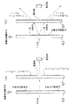
上記の受光器213−1〜213−4の受光信号からZ相信号を形成する方法を、図30、39を用いて説明する。図30は回転板の光透過部、固定板のフレネルゾーンプレートと受光部位置を示すものである。図31は、図30における光透過部205の位置に対する、受光部12−1〜12−4の受光光量の関係を示すものである。
【0199】
信号(1)、(2)、(3)、(4)は、それぞれ受光部212−1、212−2、212−3、212−4の受光光量を示す。光透過部の幅をd、フレネルゾーンプレート209−1と209−2の幅をrA 、フレネルゾーンプレート209−3と209−4の幅をrB とし、フレネルゾーンプレート209−1と209−2の境界位置をa、フレネルゾーンプレート209−3と209−4の境界位置をbとする。簡単のため、フレネルゾーンプレート209−1と209−2の幅は等しくrA/2とする。同じくフレネルゾーンプレート209−3と209−4の幅も等しくrB/2とする。
【0200】
光透過部のA部(図30中に記載)位置と信号(1)、(2)、(3)、(4)は図に示すとおりとなる。信号(1)に関して、A部の位置θ(A)がa−rA/2の位置のとき、つまり、
θ(A)=a−rA/2 ・・・(48)
のとき、受光光量が増加し始め、
θ(A)=a ・・・(49)
で受光光量が一定になり、
θ(A)=a+d−rA/2 ・・・(50)
で受光光量が減少し始め、
θ(A)=a+d ・・・(51)
のとき受光光量が一定となる。
【0201】
信号▲2▼に関しても同様に、
θ(A)=a ・・・(52)
のとき受光光量が増加し始め、
θ(A)=a+rA/2 ・・・(53)
で受光光量が一定になり、
θ(A)=a+d ・・・(54)
で受光光量が減少し始め、
θ(A)=a+d+rA/2 ・・・(55)
のとき受光光量が一定となる。信号(3)、(4)に関しても同様である。
図31は、信号(1)〜(4)からZ相信号を生成する処理方法を示したものである。信号(1)と(2)の差分信号として信号(5)を得、(3)と(4)の差分信号として信号(6)を得る。信号(5)、(6)をそれぞれゼロレベルで2値化して信号(7)、(8)を生成し、信号(7)、(8)の排他論理積から信号(9)を生成する。
【0202】
また、信号(2)と(3)の和から信号(10)を生成し、信号(10)を、信号(9)の1パルスを含むパルス信号になるような適当なしきい値で二値化して信号(11)を生成する。
これら、信号(9)と信号(11)の論理積によって、信号(12)(Zd信号とする)を得る。
【0203】
Zd信号とA/B相信号(13)との論理積をとり、これをZ相信号(14)とすることで、A/B相信号1パルスと同期したZ相信号を生成することができる。
このとき、Zd信号のパルス幅TZdと、A/B相信号のパルス幅TABを以下の関係にし、
TAB<TZd<TAB×2 ・・・(56)
Zd信号がA/B相信号1パルスのみを包括するようにすることで、論理積をとったときにA/B相信号1パルスと同期したZ相信号を得られる。
【0204】
光透過部205の中心がフレネルゾーンプレート209−1〜209−2の境界にある時に受光部212−1と212−2の差動出力がゼロになり、この点がZd信号の立ち上がり点となる。同じく、光透過部205がフレネルゾーンプレート209−3と209−4の境界にあるときに受光部212−3と212−4の差動出力がゼロになり、この点がZd信号の立ち下がり点になる。つまり、Zd信号のパルス幅は、フレネルゾーンプレート209−1と209−2の境界である位置aと、フレネルゾーンプレート209−3と209−4の境界である位置bのなす距離(角度)となる。距離|a−b|に制約はなく、どんな値でもよい。すなわち、Zd信号のパルス幅を制約なく小さくできる。上記従来例の一例で示した、10μm程度の周期であるA/B相信号と同じ程度のパルス幅のZ相信号を生成することが可能となる。
【0205】
ここで、光透過部の幅dはフレネルゾーンプレートの幅rA、rB以下である、すなわち次の関係を満たす。
d≦rA ・・・(57)
d≦rB ・・・(58)
なぜならば、光透過部幅dがフレネルゾーンプレート幅rA、rBより大きいと、2フレネルゾーンプレート境界付近において光透過部の位置が変化しても、2受光部の差動出力の変化が得られない、つまり差動出力とゼロレベルとの交叉が点でなくなってしまい、ノイズ等の影響によってZd信号の立ち上がり点が安定しなくなるからである。
【0206】
位相型回折格子やフレネルゾーンプレートは基板表面の凹凸形状により実現でき、ポリカーボネートやアクリル等の透明樹脂を用いてスタンパ工法により安価に作製することができる。
【0207】
なお、位相型回折格子206として、移動板203の移動中心を中心とする放射状の格子を用いたが、位相型回折格子206とフレネルゾーンプレート209−1〜4により形成される光スポットを受光部212−1〜4で受光しないようなもの、例えば図35に示すような同心円状の格子261、あるいは図36に示すような放射状でも同心円状でもない格子262、あるいは図37に示すようなフレネルゾーンプレート263、あるいは図38に示すような光散乱面264、あるいは図39に示すようなプリズム265、あるいは図40に示すようなレンズ266であっても同様の効果が得られる。また、固定板207上の集光性位相変調素子としてフレネルゾーンプレートを用いたが、図41に示すような通常の屈折レンズ291−1〜291−4であっても同様の効果が得られる。
【0208】
なお、本実施の形態では、固定板上の並列2集光素子2組を、移動板の移動方向に関して互いに異なる位置に設置することで、2つの差動出力のゼロクロスタイミングをずらせて2値化信号の立ち上がり部と立ち下がり部を生成したが、図34に示すように、固定板上の並列2集光素子2組を、移動板の移動方向に関して同じ位置に設置し、対応する移動板上の光透過部の位置を互いに異なるように設置しても、2つの差動出力信号のゼロクロスタイミングがずれるので、同様の効果が得られる。
【0209】
また、フレネルゾーンプレート209−1と209−2、および209−3と209−4の幅を等しくしたが、等しくなくとも同様の効果が得られる。
(実施の形態11)
本発明の光学式エンコーダ及び位置検出方法に関する実施の形態11について、図32〜図33を参照しつつ説明する。図32は本発明の光学式エンコーダの実施の形態11の基本構成を示す斜視図である。図32に示す光学式エンコーダは、半導体レーザ又は比較的可干渉性の高い発光ダイオード等の光源201と、光源201より出射された光を平行光にするコリメータレンズ202と、平行光の光軸に対して略垂直に配置され、光軸と平行な回転軸213を中心に回転可能な移動板203と、光軸に対して略垂直に配置された固定板207と、複数の受光部を有する受光器210等で構成されている。
【0210】
円盤状の移動板203は、同心円状に配置した位相型回折格子206−1、206−2、・・・206−n(但し、nは2以上の整数)(以下、206−i(i=1〜n)と一般化する。他も同様。)の一部パターンを削除することで作製した光透過部205−i−1、・・・205−i−mn(但しmnは1以上の整数)(以下、205−i−j(j=1〜mn)と一般化する。)を有する。
【0211】
固定板207は、移動板の位相型回折格子206−iに対応した位置に、フレネルゾーンプレート209−i−1〜209−i−4を有する。受光器210の受光部212−i−1〜212−i−4は、それぞれ移動板203の光透過部205−i−jと固定板207のフレネルゾーンプレート209−i−1〜209−i−4により形成される光を受光する。
【0212】
図28の構成において、回転板203の光透過部205−i−j、位相型回折格子206−iと、固定板207のフレネルゾーンプレート209−i−1〜209−i−4で光変調することにより、受光器210の受光部212−i−1〜212−i−4での受光量が変化することは、実施の形態10において図29により説明した通りであり、図30、39で説明した方法で、各トラックの2値化信号Zd1、Zd2、・・・Zdn(nは2以上の整数)を生成する。各トラックで生成される2値化信号Zdiの発生タイミングは、各光透過部205−i−jの相対位置で決まる。
【0213】
2値化信号をH及びLで記述すると、移動板の1回転中での各トラックの2値化信号H、Lの組み合わせは、移動板203の位置に依存する。移動板203がある位置のときの各トラックの2値化信号パターンが、移動板が他のいずれの位置ある時の2値化パターン信号とも異なるように、複数の各トラック信号間でパルス幅(すなわちフレネルゾーン209−i−1と209−i−2の境界と、209−i−3と209−i−4の境界の距離(角度))と発生タイミング(すなわち光透過部205−i−jの位置)を設定することで、受光信号パターンから移動板の絶対回転位置を検出することができる。移動板203の位置に特有の信号パターンが得られるので、移動板203の回転位置がどこであっても位置検出が可能なアブソリュート型光学式エンコーダとなる。
【0214】
位相型回折格子やフレネルゾーンプレートは基板表面の凹凸形状により実現でき、ポリカーボネートやアクリル等の透明樹脂を用いてスタンパ工法により安価に作製することができる。
【0215】
なお、位相型回折格子206として、移動板203の移動中心を中心とする放射状の格子も用いたが、位相型回折格子206とフレネルゾーンプレート209−1〜4により形成される光スポットを受光部212−1〜4で受光しないようなもの、例えば図42に示すような同心円状の格子261−1〜261−n、あるいは図43に示すような放射状でも同心円状でもない格子262−1〜262−n、あるいは図44に示すようなフレネルゾーンプレート263−1〜263−n、あるいは図45に示すような光散乱面264−1〜264−n、あるいは図46に示すようなプリズム265−1〜265−n、あるいは図47に示すようなレンズ266−1〜266−nであっても同様の効果が得られる。また、固定板207上の集光性位相変調素子としてフレネルゾーンプレートを用いたが、図48にしめすような通常な屈折レンズ291−1−1〜291−n−4であっても同様の効果が得られる。
【0216】
なお、本実施の形態では、固定板上の並列2集光素子2組を、移動板の移動方向に関して互いに異なる位置に設置することで、2つの差動出力のゼロクロスタイミングをずらせて2値化信号の立ち上がり部と立ち下がり部を生成したが、図34に示すように、固定板上の並列2集光素子2組を、移動板の移動方向に関して同じ位置に設置し、対応する移動板上の光透過部の位置を互いに異なるように設置しても、2つの差動出力信号のゼロクロスタイミングがずれるので、同様の効果が得られる。
【0230】
【発明の効果】
本発明の第1の光学式エンコーダによれば、光源と、前記光源から出射された光を平行光にするレンズと、集光素子及び第1のトラック群の各トラックの格子ピッチが全て異なる第1の位相型回折格子を有する移動板と、第2のトラック群の各トラックの格子ピッチが全て異なる第2の位相型回折格子を有する固定板と、前記第1の位相型回折格子と前記第2の位相型回折格子とにより生成される第1の光パターン及び前記集光素子により生成される第2の光パターンを検出する光検出器とを備え、前記集光素子の中心を通る前記移動板の中心からの直線において、前記直線上に位置する前記第1のトラック群の各トラックの格子形状は、全て凹形状か、全て凸形状か、のいずれかであり、前記第2のトラック群の各トラックは、対向する前記第1のトラック群の各トラックと同一の格子ピッチ及び同一の格子形状を有することを特徴とする。すなわち、この第1の光学式エンコーダの構成によれば、集光素子及び第1のトラック群の各トラックの格子ピッチが全て異なる第1の位相型回折格子を有する移動板の第1の位相型回折格子と固定板の第2の位相型回折格子とにより、各トラックごとに複数の周期信号を発生させ、複数の周期信号と集光素子による信号との論理積をとることにより、移動板の基準位置を特定することができる。位相型回折格子やフレネルゾーンプレート等の集光素子は、透明基板の表面の凹凸形状で実現できるため、透過性のある樹脂を用いて、スタンパ工法により安価に作製することができる。
【0231】
また、本発明の第2の光学式エンコーダによれば、光源と、前記光源から出射された光を平行光にするレンズと、第1のトラック群の各トラックの格子ピッチが全て異なる第1の位相型回折格子を有する移動板と、第2のトラック群の各トラックの格子ピッチが全て異なる第2の位相型回折格子を有する固定板と、前記第1の位相型回折格子と前記第2の位相型回折格子とにより生成される光パターンを検出する光検出器とを備え、格子ピッチが最大となるトラックの凸形状端部を通る前記移動板の中心からの直線において、前記直線上に位置する前記第1のトラック群の各トラックの格子形状は、全て凹形状か、全て凸形状か、のいずれかであり、前記第2のトラック群の各トラックは、対向する前記第1のトラック群の各トラックと同一の格子ピッチ及び同一の格子形状を有することを特徴とする。すなわち、第2の光学式エンコーダの構成によれば、第1及び第2の位相型回折格子は、格子ピッチが最大となるトラックの凸形状端部を通る前記移動板の中心からの直線において、前記直線上に位置する前記第1のトラック群の各トラックの格子形状は、全て凹形状か、全て凸形状か、のいずれかであり、前記第2のトラック群の各トラックは、対向する前記第1のトラック群の各トラックと同一の格子ピッチ及び同一の格子形状を有しているため、各トラックごとに発生される周期信号はそれぞれパターンが異なるように設定される。各瞬間ごとのパターンをあらかじめ記憶しておいたパターンと比較することにより、移動板が現在移動基準位置からどの位置にあるのかを絶対的に判断することができる。
【図面の簡単な説明】
【図1】本発明の実施の形態1に係る光学式エンコーダの概略構成図
【図2】上記実施の形態1における効果説明のための、フレネルゾーンプレートの作用を示す光路図
【図3】上記実施の形態1における効果説明のため、光の経路を示した光路図
【図4】本発明の実施の形態2に係る光学式エンコーダの概略構成図
【図5】上記実施の形態2における効果説明のため、光の経路を示した光路図
【図6】本発明の実施の形態3に係る光学式エンコーダの概略構成図
【図7】上記実施の形態3における効果説明のための、光の経路を示した光路図
【図8】本発明の実施の形態4に係る光学式エンコーダの概略構成図
【図9】上記実施の形態4における効果説明のための、光の経路を示した光路図
【図10】本発明の実施の形態5に係る光学式エンコーダの概略構成図
【図11】上記実施の形態5における効果説明のための、光の経路を示した光路図
【図12】本発明の実施の形態6の光学式エンコーダの構成を示す斜視図
【図13】実施の形態6の位相光学素子の各トラックの断面形状を示す図
【図14】図13に示す位相光学素子の断面形状の一部分拡大した図
【図15】実施の形態6における受光部の出力信号を示す図
【図16】図15に示す出力信号の一部分を拡大した図
【図17】本発明の実施の形態7における光学式エンコーダの構成を示す斜視図
【図18】実施の形態7における位相光学素子の断面形状を示す図
【図19】実施の形態7における受光部の出力信号を示す図
【図20】本発明の実施の形態8における光学式エンコーダの構成を示す斜視図
【図21】実施の形態8における光学式エンコーダの光路図
【図22】実施の形態8における位相光学素子の断面形状を示す図
【図23】実施の形態8における受光部の出力信号を示す図
【図24】本発明の実施の形態9における光学式エンコーダの構成を示す斜視図
【図25】実施の形態9における光学式エンコーダの光路図
【図26】実施の形態9における位相光学素子の断面形状を示す図
【図27】実施の形態9における受光部の出力信号を示す図
【図28】本発明の実施の形態10における光学式エンコーダの構成を示す斜視図
【図29】実施の形態10における光変調の様子を示す光路図
【図30】実施の形態10における変調素子位置を示す図
【図31】実施の形態10の出力信号生成過程を示す図
【図32】本発明の実施の形態11における光学式エンコーダの構成を示す斜視図
【図33】実施の形態11の出力信号例を示す図
【図34】実施の形態10における別の変調素子位置を示す図
【図35】実施の形態10における光学式エンコーダの別の構成を示す斜視図
【図36】実施の形態10における光学式エンコーダの別の構成を示す斜視図
【図37】実施の形態10における光学式エンコーダの別の構成を示す斜視図
【図38】実施の形態10における光学式エンコーダの別の構成を示す斜視図
【図39】実施の形態10における光学式エンコーダの別の構成を示す斜視図
【図40】実施の形態10における光学式エンコーダの別の構成を示す斜視図
【図41】実施の形態10における光学式エンコーダの別の構成を示す斜視図
【図42】実施の形態11における光学式エンコーダの別の構成を示す斜視図
【図43】実施の形態11における光学式エンコーダの別の構成を示す斜視図
【図44】実施の形態11における光学式エンコーダの別の構成を示す斜視図
【図45】実施の形態11における光学式エンコーダの別の構成を示す斜視図
【図46】実施の形態10における光学式エンコーダの別の構成を示す斜視図
【図47】実施の形態11における光学式エンコーダの別の構成を示す斜視図
【図48】実施の形態11における光学式エンコーダの別の構成を示す斜視図
【図49】第1の従来例の光学式エンコーダの構成を示す斜視図
【図50】従来の遮光パターンを作製するプロセス図
【図51】従来のスタンバ工法による位相型回折格子の作成プロセス図
【図52】第1の従来例の光学式エンコーダの別の構成例及び光路を示す図
【図53】第1の従来例の光学式エンコーダのさらに別の構成例及び光路を示す図
【図54】光源の大きさとレンズ定数と光スポットとの関係を説明するための光路図
【図55】第2の従来例の光学式エンコーダの構成を示す斜視図
【図56】第3の従来例の位置検出装置の概略構成を示す図
【符号の説明】
1,101,201 光源
2,102,202 コリメータレンズ
3,114,213 回転軸
4,103,203 移動板
5,107,207 固定板
6,110,210 受光器
7,9,104,105,108,109,204,206,208 回折格子
8,10,106,143 フレネルゾーンプレート
11,32,111,112,113,211,212 受光部
21 凹レンズ
22,42,52 凸レンズ
31 ハーフミラー
41 光散乱源
51 反射面
141,205 光透過部
209 集光素子
φa,φa2,φa3,φa4,φa5 光源の大きさ
δb1,δb12,δb13,δb14,δb15 移動板の移動量
δc,δd2,δc3,δc4,δc5 光スポットの移動量
φc,φd2,φc3,φc4,φc5 光スポットの大きさ
w,w2,w3,w4,w5 受光部の巾
g,g2,g3,g4,g5 移動板と固定板間の距離
fa,fa2,fa3 コリメータレンズの焦点距離
fb1,fb12 移動板上のフレネルゾーンプレートの焦点距離
fb2,fb22 固定板上のフレネルゾーンプレートの焦点距離
fb13 移動板上のレンズの焦点距離
fb23,fb24,fb25 固定板上のレンズの焦点距離
fc,fc3,fc4,fc5 固定板から光スポットまでの距離
fc2 移動板上のフレネルゾーンプレートに入射した光が固定板上のフレネルゾ−ンプレートで集光される点から固定板間での距離
fd2 移動板から光スポットまでの距離
φb4 移動板上の光散乱源の大きさ
φb5 移動板上の反射面の大きさ
Pi〜Pn 位相型回折格子のピッチ(但し、i=0〜n、nは2以上の整数)
A 受光部12での受光信号を2値化した信号
Zi 受光部13−iでの受光信号の2値化信号
Zd 受光部11での受光信号を2値化した信号
Z A、Z1、Z2、Zn・・Zdの論理積信号
a7 光源の発光径
b7 コリメータレンズの焦点距離
c7 フレネルゾーンプレートの焦点距離
c7d フレネルゾーンプレートから受光部までの距離
d7 集光スポット径[0001]
BACKGROUND OF THE INVENTION
The present invention relates to an optical encoder used for positioning in a mechanical device or the like and a position detection method thereof.
[0002]
[Prior art]
(First conventional example)
In general, optical encoders are roughly classified into two types, an incremental type and an absolute type (absolute position detection type), depending on the position detection method. The configuration and operation of a conventional incremental optical encoder will be described. As shown in FIG. 49, a conventional incremental optical encoder includes a
[0003]
The moving
[0004]
By detecting the light transmitted through the A / B phase signal regions (
[0005]
Next, a method for producing a light shielding pattern such as a slit will be described with reference to FIG. As shown in FIG. 50, a
[0006]
As described above, many steps are required to manufacture the
[0007]
The phase-type optical element can be produced by providing an uneven shape on the substrate surface. The manufacturing process is shown in FIG. A transparent resin 532 such as acrylic or polycarbonate that has been made fluid by heating or the like is poured into a mold 531 having a predetermined shape and solidified. The shape of the mold is transferred to the obtained phase type optical element. According to this method, it is not necessary to align the substrate with the pattern as compared with a method for producing a light-shielding pattern such as a slit on the substrate surface. Steps such as vapor deposition and cleaning are unnecessary.
[0008]
As an example in which the A / B phase signal region is a phase type diffraction grating which is one of phase optical elements, a conventional incremental type encoder shown in JP 6-042981 is known, for example. The configuration is shown in FIG. In FIG. 52, a
[0009]
On the other hand, as in the case of the A / B phase signal region, a method for forming a concavo-convex shape on the surface of the Z phase signal region instead of the slit is being sought. For example, as shown in FIG. 53, a
(Second conventional example)
The incremental optical encoder shown in FIG. 49 detects the position of the moving
[0010]
The configuration and operation of the absolute optical encoder will be described. As shown in FIG. 55, a conventional absolute optical encoder rotates around an
(Third conventional example)
Conventionally, an object is irradiated with light, its image is projected onto a TV camera, the output signal of the linear array sensor is binarized to detect the position, or the object is moved and slit (hereinafter referred to as a moving object). The position of the object can be detected in a non-contact manner by allowing the light emitted from the light source to enter the light receiving section through this slit and binarizing the output signal of the light receiving section to detect the movement reference point of the moving body. Is widely practiced. For example, a conventional position detection method shown in JP2-44220 will be described with reference to FIG.
[0011]
FIG. 56 is a plan view of a position detection apparatus as a third conventional example. In FIG. 56,
[0012]
δδ = Δ · B / AA (1)
[0013]
[Problems to be solved by the invention]
In the incremental encoder according to the first conventional example, when the Z-phase signal region is formed to have a concavo-convex shape on the surface instead of the slit, it is difficult to increase the Z-phase detection accuracy. The size of the focused spot diameter is determined by the size of the
[0014]
φs2 = φs1 · fs2 / fs1 (2)
Therefore, in order to reduce the diameter φs2 of the
[0015]
Usually, a light emitting diode is used as the
[0016]
Furthermore, this method has a problem that it is difficult to synchronize the A / B phase signal, which is a signal for detecting the amount of movement of the moving
[0017]
In the absolute encoder as the second conventional example, a plurality of slit tracks are provided on the moving
[0018]
In the position detection method as the third conventional example, in order to increase the detection accuracy of the movement reference point of the moving
[0019]
In view of the above-described problems of the conventional example, the present invention enables highly accurate movement reference point detection, that is, highly accurate Z-phase signal detection, while synchronizing the Z-phase signal and the A / B-phase signal in the optical encoder. It aims to be. It is another object of the present invention to provide an optical encoder and a position (angle) detection method capable of ensuring a sufficient distance between the moving body and the light receiving unit and generating a signal with the uneven shape of the moving plate and the fixed plate. . Furthermore, it aims at providing the optical encoder and position detection method which detect the absolute position of a moving plate with the signal which arises by the uneven | corrugated shape of a moving plate and a fixed plate.
[0045]
[Means for Solving the Problems]
In order to achieve the above-described object, a first optical encoder of the present invention includes a light source, a lens that collimates light emitted from the light source,All the grating pitches of each track of the condensing element and the first track groupMoving plates having different first phase type diffraction gratings;Of the second track groupEach trackOfLattice pitchAre all differentSecond phase type diffraction caseChildAnd the first phase type diffraction grating and the second phase type diffraction grating.FirstGenerated by the light pattern and the light collecting elementSecondAnd a light detector for detecting a light patternIn the straight line from the center of the moving plate passing through the center of the light collecting element, the lattice shape of each track of the first track group located on the straight line is all concave or convex. Each of the tracks in the second track group has the same lattice pitch and the same lattice shape as each of the tracks in the first track group facing each other.
[0046]
That is, the first optical encoder of the present invention isThe first phase-type diffraction grating having different grating pitches for each track of the light collecting element and the first track group.A plurality of periodic signals are generated for each track by the first phase type diffraction grating of the moving plate and the second phase type diffraction grating of the fixed plate, and a logical product of the plurality of periodic signals and the signal from the light collecting element is obtained. The reference position of the moving plate is specified by taking
[0048]
In the first optical encoder,Assuming that periodic signals in the tracks of the first and third phase type diffraction gratings are So and Si (i = 1 to n, n is an integer of 2 or more), the respective periods VSo and VSi are expressed by the formula (3). In the vicinity of the movement reference point, only one Si pulse exists in the vicinity of the movement reference point.IncludeIt is preferable.
[0049]
In addition, it is preferable that a signal pulse generated by receiving a condensing spot formed by the condensing element on the moving plate in the vicinity of the movement reference point includes only one Sn pulse.
[0050]
The second optical encoder of the present invention includes a light source, a lens that collimates the light emitted from the light source,All grid pitches of each track in the first track groupMoving plates having different first phase type diffraction gratings;The lattice pitch of each track of the second track group is all differentA fixed plate having a second phase type diffraction grating, and a photodetector for detecting a light pattern generated by the first phase type diffraction grating and the second phase type diffraction grating.In the straight line from the center of the moving plate passing through the convex end of the track where the lattice pitch is maximum, the lattice shape of each track of the first track group located on the straight line is all concave, All of the tracks have a convex shape, and each track of the second track group has the same grid pitch and the same grid shape as each track of the first track group facing each other. .
[0051]
That is, in the second optical encoder of the present invention, the first and second phase type diffraction gratings each have a plurality of tracks having different grating pitches.In the straight line from the center of the moving plate passing through the convex end of the track where the lattice pitch is maximum, the lattice shape of each track of the first track group located on the straight line is all concave, All of the tracks are convex, and each track of the second track group has the same grid pitch and the same grid shape as the tracks of the first track group facing each other.Therefore, the periodic signal generated for each track has a different pattern.It is set as follows.By comparing the pattern for each moment with the pattern stored in advance, it is possible to absolutely determine the position of the moving plate from the current movement reference position.
[0053]
In the second optical encoder,It is preferable that a plurality of periodic signals of the photodetector are So and Si (i = 1 to n, n is an integer of 2 or more), respectively, and each period VSo and VSi satisfies the condition of the expression (4).
[0086]
DETAILED DESCRIPTION OF THE INVENTION
Hereinafter, embodiments of the present invention will be described with reference to the drawings.
(Embodiment 1)
FIG. 1 is a basic configuration diagram of an optical
[0087]
In FIG. 1,
[0088]
The moving
[0089]
The fixed
[0090]
Here, the operation of the Fresnel zone plate 8 (10) will be described with reference to FIG. FIG. 2 shows a sectional view of the Fresnel zone plate and how light is modulated by the Fresnel zone plate.
[0091]
The
[0092]
In the
[0093]
The operation of the above configuration will be described with reference to FIG. FIG. 3 is a path diagram of light passing through the
First, the light emitted from the
[0094]
fc = (fb1 + g) fb2 / (fb1 + g−fb2) (7)
The
[0095]
δc = δb1 · fc / fb1 (8)
Furthermore, when the size of the
[0096]
[0097]
[0098]
Further, according to the first embodiment, the Z-phase signal is a signal having a waveform determined by the relative positional relationship between the moving
[0099]
As an example, if the
[0100]
Further, by adjusting the relationship between the width w of the
[0101]
In the first embodiment, the
[0102]
A more effective action can be obtained when a
[0103]
As an example of the first embodiment, fa = 4.5 mm, fb1 = 0.6 mm, fb2 = 0.7 mm, and g = 0.3 mm are used. can get.
[0104]
(Embodiment 2)
FIG. 4 is a basic configuration diagram of an optical
[0105]
In FIG. 4, 21 is a concave lens provided on the moving
[0106]
The operation of the above configuration will be described with reference to FIG.
First, the light emitted from the
[0107]
If the focal lengths of the
[0108]
δc3 = δb13 · fc3 / fb13 (12)
Furthermore, if the size of the
[0109]
[0110]
[0111]
Furthermore, according to the second embodiment, the Z-phase signal is a waveform signal determined by the relative positional relationship between the moving
[0112]
As an example, if the
[0113]
Further, by adjusting the relationship between the width w3 of the
[0114]
In the second embodiment, the
[0115]
Note that a more effective action can be obtained when a light source such as a light emitting diode having a relatively large light emitting portion such as a light emitting portion whose diameter is several times the wavelength or more is used.
[0116]
As an example of the second embodiment, fa3 = 4.5 mm, fb13 = 0.6 mm, fb23 = 0.7 mm, and g3 = 0.3 mm are used. can get.
[0117]
(Embodiment 3)
FIG. 6 is a basic configuration diagram of an optical
[0118]
In FIG. 6,
[0119]
The operation of the above configuration will be described with reference to FIG.
First, the light emitted from the
[0120]
When the focal lengths of the
[0121]
[0122]
[0123]
δd2 = δb12 · fd2 / fb12 (17)
The size (diameter) φd2 of the condensing spot S6 is given by the equation (18) by the size φa2 of the light source and the focal length fa2 of the
[0124]
φd2 = φa2 / fd2 / fa2 (18)
Therefore, by adjusting the focal length fb12 of the
[0125]
Furthermore, according to the third embodiment, the Z-phase signal is a signal having a waveform determined by the relative positional relationship between the moving
As an example, if the
[0126]
Further, by adjusting the relationship between the width w2 of the
In the third embodiment, the
[0127]
A more effective action can be obtained when a
[0128]
As an example of the third embodiment, the case of fa2 = 4.5 mm, fb12 = 1 mm, fb22 = 5 mm, and g2 = 0.3 mm is used, but an effective action can be obtained with other than this.
[0129]
(Embodiment 4)
FIG. 8 is a basic configuration diagram of an optical
[0130]
In FIG. 8,
[0131]
The operation of the above configuration will be described with reference to FIG.
First, the light emitted from the
[0132]
When the focal length of the
[0133]
fc4 = g4 · fb24 / (g4-fb24) (19)
The
[0134]
δc4 = δb14 · fc4 / g4 (20)
If the size of the
[0135]
φc4 = φb4 · fc4 / g4 (21)
Accordingly, the size (diameter) φc4 of the light spot S7 becomes E times the size φa4 of the
[0136]
E = φb4 · fc4 / (g4 · φa4)
F = fc4 / g4 (22)
Therefore, by adjusting the values of the
[0137]
Furthermore, according to the fourth embodiment, the Z-phase signal is a signal having a waveform determined by the relative positional relationship between the moving
[0138]
As an example, if a
[0139]
In addition, since the
[0140]
Although the
[0141]
Note that, as an example of the fourth embodiment, the case where fb24 = 0.2 mm, g4 = 0.3 mm, and φb4 = 50 μm is used.
[0142]
(Embodiment 5)
FIG. 10 is a basic configuration diagram of an optical
[0143]
In FIG. 10,
[0144]
The operation of the above configuration will be described with reference to FIG.
First, the light emitted from the
[0145]
If the focal length of the
[0146]
fc5 = g5 · fb25 / (g5-fb25) (23)
The
[0147]
δc5 = δb15 · fc5 / g5 (24)
When the size of the reflecting
[0148]
φc5 = φb5 · fc5 / g5 (25)
As a result, the size (diameter) φc5 of the light spot S8 is G times the size φa5 of the
[0149]
G = φb5 · fc5 / (g5 · φa5)
H = fc5 / g5 (26)
Therefore, by adjusting the values of the size φb5 of the reflecting
[0150]
Furthermore, the Z-phase detection accuracy can be increased by reducing the size of the reflecting
[0151]
Further, according to the fifth embodiment, the Z-phase signal is a signal having a waveform determined by the relative positional relationship between the moving
[0152]
As an example, if a
[0153]
In addition, since the
[0154]
Although the
[0155]
As an example of the fifth embodiment, fb25 = 0.2 mm, g5 = 0.3 mm, and φb5 = 50 μm are used, but an effective action can be obtained with other than this.
(Embodiment 6)
[0156]
The disc-shaped moving
[0157]
FIG. 13 shows the cross-sectional shape of each phase type diffraction grating. In FIG. 13, FIG. 13A shows the cross-sectional shape of the phase
[0158]
The phase-
[0159]
[0160]
Here, the 0 ° line in FIGS. 12 and 13 is a position where a Z-phase signal is to be generated, and is assumed for the moving
[0161]
In the phase-
In FIG. 14B, “b” represents a distance (angle) from the 0 ° line to the
[0162]
Regarding the positional relationship between the phase-
[0163]
| A | ≦ | b | ≦ | a + P0 / 2 | (30)
| P0 / 2-a | ≦ | P1 / 2−b | ≦ | P0−a | (31)
Similarly, with respect to the relationship between the gratings 105-1 and 109-1 and 105-2 and 109-2, the grating convex portions through which the 0 ° lines of the phase-type diffraction gratings 105-2 and 109-2 pass are phase-type diffraction. A condition is satisfied that includes only one lattice convex portion through which the 0 ° lines of the lattices 105-1 and 109-1 pass. That is, the distance (angle) from the 0 ° line to the positive ends of the lattice convex portions of the lattices 105-2 and 109-2 through which the 0 ° line passes is “c” (not shown), and from the 0 ° line. The distance (angle) to the negative end of the grating convex part through which the 0 ° line passes is “P2 / 2-c”, and the 0 ° line from the 0 ° line in the phase diffraction gratings 105-1 and 109-1 The distance (angle) from the grid convex part passing through to the edge starting from the grid convex part adjacent in the positive direction is “b + P1 / 2”, and from the 0 ° line to the negative end of the grid convex part through which the 0 ° line passes The following formulas (32) and (33) are established with the distance (angle) of “P1−b”.
[0164]
| B | ≦ | c | ≦ | b + P1 / 2 | (32)
| P1 / 2-b | ≦ P2 / 2-c | ≦ | P1-b | (33)
Hereinafter, the relationship between the phase type diffraction gratings 105-2 and 109-2 and 105-3 and 109-3,..., The phase type diffraction gratings 105- (n-1) and 109- (n-1) and 105- The same applies to the relationship between n and 109-n.
[0165]
The
[0166]
As shown in FIGS. 13 and 14, each phase type diffraction grating has a grating convex portion through which the 0 ° line of the phase type diffraction gratings 105-1 and 109-1 passes, and the 0 ° line of the phase
[0167]
FIG. 16 is an enlarged view in the vicinity of the 0 point of each signal shown in FIG. 15, and represents the relationship between the signals. The zero point means the moment when the 0 ° line of the moving
[0168]
The relationship between the signals A and Z1 is that the condition that the
[0169]
| Α | ≦ | β1 | ≦ | α + P0 / 4 | (34)
| P0 / 4-α | ≦ | P1 / 4-β1 | ≦ | P0 / 2-α | (35)
Similarly, with respect to the relationship between the signals Z1 and Z2, the condition that the
[0170]
[0171]
[0172]
As described in the description of the conventional example, the period of the signal to be generated can be reduced by relatively changing the phase-type diffraction grating having an equal pitch such as A, Z1,. On the other hand, the width of the signal generated by spot light detection by a condensing element such as the
[0173]
Further, a signal A which is simply an A / B phase signal and a signal Zd which is a signal for generating a Z phase signal are generated, and one A / B phase signal pulse is generated from the moment when the Zd pulse is generated. It is also possible to use a method of extracting the signal as a Z-phase signal. However, the Zd pulse does not always occur at a constant timing due to various factors such as electrical noise, mechanical vibration, and the like. The allowable value of the Zd generation timing deviation is one concave portion of the signal A, that is, P0 / 4. On the other hand, if the logical product of A, Z1, Z2,... Zn and Zd is taken as a Z-phase signal, the allowable value of the Zd generation timing deviation is equivalent to one recess of the signal Zn, that is, , Pn / 4. From the conditions shown in the above equations (30) to (33), Pn / 4 ≧ P0 / 4 holds. That is, according to the present invention, an allowable value for the timing deviation of Zd generation can be increased, and an optical encoder that is resistant to electrical noise, mechanical vibration, and the like can be realized. Further, since the phase
[0174]
Note that the 0 ° line passes through the grating convex portions for all of the phase
[0175]
Further, regarding the moving
(Embodiment 7)
Next, a seventh embodiment relating to the optical encoder and position detection method of the present invention will be described with reference to FIGS. FIG. 17 is a perspective view showing the basic configuration of the optical encoder according to the seventh embodiment of the present invention. The optical encoder shown in FIG. 17 includes a
[0176]
The disc-shaped moving
[0177]
Similar to the sixth embodiment of the present invention, the light incident on the moving
[0178]
At this time, the detection signal by each light receiving unit 132-i (i = 0 to n) is a sinusoidal signal having a period of ½ of the grating pitch of the phase type diffraction grating. As shown in FIG. 17, the phase type diffraction grating 130-i (i = 0 to n) of the moving
[0179]
FIG. 18 shows cross-sectional shapes of phase-type diffraction gratings 130-i (i = 0 to n) and 131-i (i = 0 to n) near the 0 ° line on the moving
[0180]
[0181]
Thus, the combination of the H and L signals of each light receiving unit 132-i (i = 0 to n) depends on the position of the moving
[0182]
The phase type diffraction grating can be realized by the uneven shape of the substrate surface, and can be manufactured at low cost by a stamper method using a transparent resin such as polycarbonate or acrylic. In the seventh embodiment, the phase-type diffraction gratings 130-i and 131-i (i = 0 to n) on the moving
(Embodiment 8)
Next, an eighth embodiment relating to the optical encoder and position detection method of the present invention will be described with reference to FIGS. FIG. 20 is a perspective view showing the basic configuration of the optical encoder according to the eighth embodiment of the present invention. An optical encoder shown in FIG. 20 includes a
[0183]
The disc-shaped moving
[0184]
An optical path diagram of the optical encoder according to the eighth embodiment of the present invention is shown in FIG. In FIG. 21, the position of the moving
FIG. 22 shows cross-sectional shapes of the phase diffraction gratings 140-0, 140-1,... 140- (n−1), 140-n in the vicinity of the 0 ° line on the moving
[0185]
[0186]
Thus, the combination of the H and L signals of each light receiving unit 142-i (i = 0 to n) depends on the position of the moving
[0187]
The phase-type diffraction grating can be realized by the uneven shape on the substrate surface, and can be manufactured at low cost by a stamper method using a transparent resin such as polycarbonate or acrylic. In the eighth embodiment, the phase type diffraction grating 140-i (i = 0 to n) on the moving
Next, a ninth embodiment relating to the optical encoder and position detection method of the present invention will be described with reference to FIGS. FIG. 24 is a perspective view showing the basic configuration of the optical encoder according to the ninth embodiment of the present invention. The optical encoder shown in FIG. 24 includes a
[0188]
The disc-shaped moving
[0189]
An optical path diagram of the optical encoder according to the ninth embodiment of the present invention is shown in FIG. The position of the moving
[0190]
FIG. 26 shows a cross section of the light collecting element 150-i (i = 0 to n) in the vicinity of the 0 ° line on the moving
[0191]
[0192]
As described above, the combination of the H and L signals of each light receiving unit 52-i (i = 0 to n) depends on the position of the moving
[0193]
A condensing element such as a Fresnel zone plate can be realized as a concavo-convex shape on the surface of the substrate, and therefore can be manufactured at low cost by a stamper method using a transparent resin such as polycarbonate or acrylic. In the ninth embodiment, the condensing elements are arranged along the 0 ° line of the moving
(Embodiment 10)
The tenth embodiment relating to the optical encoder and position detection method of the present invention will be described with reference to FIGS. FIG. 28 is a perspective view showing the basic structure of the optical encoder according to the tenth embodiment of the present invention. The optical encoder shown in FIG. 28 includes a
[0194]
The disc-shaped moving
[0195]
In the configuration of FIG. 28, the
[0196]
Depending on the rotational position of the moving
Δ = L × tan θ1> δ (46)
By satisfying the above relationship, it is possible to prevent the light-receiving portion from receiving the focused spot of the Fresnel zone plate.
[0197]
The grating pitch P and diffraction angle θ1 of the phase
sin θ1 = λ / P (47)
It is well known that there is a relationship. Therefore, relationships such as the grating pitch of the phase-
[0198]
A method of forming a Z-phase signal from the light reception signals of the above-described light receivers 213-1 to 213-4 will be described with reference to FIGS. FIG. 30 shows the light transmitting portion of the rotating plate, the Fresnel zone plate of the fixed plate, and the position of the light receiving portion. FIG. 31 shows the relationship of the amount of light received by the light receiving units 12-1 to 12-4 with respect to the position of the
[0199]
Signals (1), (2), (3), and (4) indicate the amounts of light received by the light receiving sections 212-1, 212-2, 212-3, and 212-4, respectively. The width of the light transmitting portion is d, the width of the Fresnel zone plates 209-1 and 209-2 is rA, the width of the Fresnel zone plates 209-3 and 209-4 is rB, and the Fresnel zone plates 209-1 and 209-2 The boundary position is a, and the boundary position between Fresnel zone plates 209-3 and 209-4 is b. For simplicity, the widths of the Fresnel zone plates 209-1 and 209-2 are equal to rA / 2. Similarly, the widths of the Fresnel zone plates 209-3 and 209-4 are also equal to rB / 2.
[0200]
The position of the light transmission part A (described in FIG. 30) and the signals (1), (2), (3), and (4) are as shown in the figure. Regarding the signal (1), when the position θ (A) of the A part is at the position of a−rA / 2, that is,
θ (A) = a−rA / 2 (48)
When the received light quantity begins to increase,
θ (A) = a (49)
With the received light quantity becomes constant,
θ (A) = a + d−rA / 2 (50)
The received light intensity starts to decrease,
θ (A) = a + d (51)
In this case, the amount of received light is constant.
[0201]
Similarly for signal (2)
θ (A) = a (52)
The received light intensity starts to increase at
θ (A) = a + rA / 2 (53)
With the received light quantity becomes constant,
θ (A) = a + d (54)
The received light intensity starts to decrease,
θ (A) = a + d + rA / 2 (55)
In this case, the amount of received light is constant. The same applies to the signals (3) and (4).
FIG. 31 shows a processing method for generating a Z-phase signal from signals (1) to (4). The signal (5) is obtained as the difference signal between the signals (1) and (2), and the signal (6) is obtained as the difference signal between (3) and (4). The signals (5) and (6) are binarized at zero level to generate signals (7) and (8), and the signal (9) is generated from the exclusive logical product of the signals (7) and (8).
[0202]
Further, the signal (10) is generated from the sum of the signals (2) and (3), and the signal (10) is binarized with an appropriate threshold value so as to become a pulse signal including one pulse of the signal (9). To generate a signal (11).
The signal (12) (referred to as Zd signal) is obtained by the logical product of the signal (9) and the signal (11).
[0203]
A Z-phase signal synchronized with one pulse of the A / B-phase signal can be generated by taking the logical product of the Zd signal and the A / B-phase signal (13) and using this as the Z-phase signal (14). .
At this time, the pulse width TZd of the Zd signal and the pulse width TAB of the A / B phase signal have the following relationship:
TAB <TZd <TAB × 2 (56)
By making the Zd signal include only one pulse of the A / B phase signal, a Z phase signal synchronized with the one pulse of the A / B phase signal can be obtained when the logical product is taken.
[0204]
When the center of the
[0205]
Here, the width d of the light transmission part is equal to or less than the widths rA and rB of the Fresnel zone plate, that is, the following relationship is satisfied.
d ≦ rA (57)
d ≦ rB (58)
This is because if the light transmission part width d is larger than the Fresnel zone plate widths rA and rB, the differential output of the two light receiving parts can be changed even if the position of the light transmission part changes near the boundary between the two Fresnel zone plates. This is because the crossover between the differential output and the zero level is no longer a point, and the rising point of the Zd signal becomes unstable due to the influence of noise or the like.
[0206]
The phase type diffraction grating and the Fresnel zone plate can be realized by the uneven shape of the substrate surface, and can be manufactured at low cost by a stamper method using a transparent resin such as polycarbonate or acrylic.
[0207]
Although a radial grating centered on the moving center of the moving
[0208]
In the present embodiment, two sets of parallel two condensing elements on the fixed plate are placed at different positions with respect to the moving direction of the moving plate, thereby binarizing by shifting the zero-cross timing of the two differential outputs. As shown in FIG. 34, the rising and falling portions of the signal are generated. Two sets of parallel two condensing elements on the fixed plate are installed at the same position with respect to the moving direction of the moving plate, and on the corresponding moving plate. Even if the positions of the light transmitting portions are different from each other, the zero-cross timings of the two differential output signals are shifted, and the same effect can be obtained.
[0209]
Further, although the widths of the Fresnel zone plates 209-1 and 209-2 and 209-3 and 209-4 are equal, the same effect can be obtained even if they are not equal.
(Embodiment 11)
The eleventh embodiment relating to the optical encoder and position detection method of the present invention will be described with reference to FIGS. FIG. 32 is a perspective view showing the basic structure of the optical encoder according to the eleventh embodiment of the present invention. The optical encoder shown in FIG. 32 includes a
[0210]
The disc-shaped moving
[0211]
The fixed
[0212]
In the configuration of FIG. 28, light modulation is performed by the light transmitting portion 205-i-j of the
[0213]
When the binarized signal is described by H and L, the combination of the binarized signals H and L of each track during one rotation of the moving plate depends on the position of the moving
[0214]
The phase type diffraction grating and the Fresnel zone plate can be realized by the uneven shape of the substrate surface, and can be manufactured at low cost by a stamper method using a transparent resin such as polycarbonate or acrylic.
[0215]
In addition, although the radial grating centering on the moving center of the moving
[0216]
In the present embodiment, two sets of parallel two condensing elements on the fixed plate are placed at different positions with respect to the moving direction of the moving plate, thereby binarizing by shifting the zero-cross timing of the two differential outputs. As shown in FIG. 34, the rising and falling portions of the signal are generated. Two sets of parallel two condensing elements on the fixed plate are installed at the same position with respect to the moving direction of the moving plate, and on the corresponding moving plate. Even if the positions of the light transmitting portions are different from each other, the zero-cross timings of the two differential output signals are shifted, and the same effect can be obtained.
[0230]
【The invention's effect】
According to the first optical encoder of the present invention, a light source, a lens that collimates the light emitted from the light source,All the grating pitches of each track of the condensing element and the first track groupDifferent first phase type diffraction caseChildA moving plate having,Of the second track groupEach trackOfLattice pitchAre all differentProduced by a fixed plate having a second phase type diffraction grating, the first phase type diffraction grating and the second phase type diffraction gratingFirstGenerated by the light pattern and the light collecting elementSecondAnd a light detector for detecting a light patternIn the straight line from the center of the moving plate passing through the center of the light collecting element, the lattice shape of each track of the first track group located on the straight line is all concave or convex. Each of the tracks in the second track group has the same lattice pitch and the same lattice shape as each of the tracks in the first track group facing each other.That is, according to the configuration of the first optical encoder,The first phase-type diffraction grating having different grating pitches for each track of the light collecting element and the first track group.A plurality of periodic signals are generated for each track by the first phase type diffraction grating of the moving plate and the second phase type diffraction grating of the fixed plate, and a logical product of the plurality of periodic signals and the signal from the light collecting element is obtained. By taking, the reference position of the moving plate can be specified. A condensing element such as a phase-type diffraction grating or a Fresnel zone plate can be realized with a concavo-convex shape on the surface of a transparent substrate, and therefore can be manufactured at low cost by a stamper method using a transparent resin.
[0231]
Further, according to the second optical encoder of the present invention, a light source, a lens that collimates the light emitted from the light source,All grid pitches of each track in the first track groupMoving plates having different first phase type diffraction gratings;The lattice pitch of each track of the second track group is all differentA fixed plate having a second phase type diffraction grating, and a photodetector for detecting a light pattern generated by the first phase type diffraction grating and the second phase type diffraction grating.In the straight line from the center of the moving plate passing through the convex end of the track where the lattice pitch is maximum, the lattice shape of each track of the first track group located on the straight line is all concave, All of the tracks have a convex shape, and each track of the second track group has the same grid pitch and the same grid shape as each track of the first track group facing each other. .That is, according to the configuration of the second optical encoder, the first and second phase type diffraction gratings are:In a straight line from the center of the moving plate passing through the convex end of the track having the largest lattice pitch, the lattice shape of each track of the first track group located on the straight line is all concave or all Each track of the second track group has the same grid pitch and the same grid shape as each track of the first track group facing each other.Therefore, the periodic signal generated for each track has a different pattern.It is set as follows.By comparing the pattern for each moment with the pattern stored in advance, it is possible to absolutely determine the position of the moving plate from the current movement reference position.
[Brief description of the drawings]
FIG. 1 is a schematic configuration diagram of an optical encoder according to a first embodiment of the present invention.
FIG. 2 is an optical path diagram showing the action of a Fresnel zone plate for explaining the effect in the first embodiment.
FIG. 3 is an optical path diagram showing a light path for explaining the effect in the first embodiment.
FIG. 4 is a schematic configuration diagram of an optical encoder according to a second embodiment of the present invention.
FIG. 5 is an optical path diagram showing a light path for explaining the effect in the second embodiment.
FIG. 6 is a schematic configuration diagram of an optical encoder according to a third embodiment of the present invention.
FIG. 7 is an optical path diagram showing a light path for explaining the effect in the third embodiment.
FIG. 8 is a schematic configuration diagram of an optical encoder according to a fourth embodiment of the present invention.
FIG. 9 is an optical path diagram showing a light path for explaining the effect in the fourth embodiment.
FIG. 10 is a schematic configuration diagram of an optical encoder according to a fifth embodiment of the present invention.
FIG. 11 is an optical path diagram showing a light path for explaining the effect in the fifth embodiment.
FIG. 12 is a perspective view showing a configuration of an optical encoder according to a sixth embodiment of the present invention.
13 is a diagram showing a cross-sectional shape of each track of the phase optical element according to the sixth embodiment.
14 is a partially enlarged view of the cross-sectional shape of the phase optical element shown in FIG.
15 is a diagram showing an output signal of a light receiving unit in
16 is an enlarged view of a part of the output signal shown in FIG.
FIG. 17 is a perspective view showing a configuration of an optical encoder according to a seventh embodiment of the present invention.
FIG. 18 is a diagram showing a cross-sectional shape of a phase optical element in the seventh embodiment
19 is a diagram showing an output signal of a light receiving unit in
FIG. 20 is a perspective view showing a configuration of an optical encoder according to an eighth embodiment of the present invention.
FIG. 21 is an optical path diagram of an optical encoder according to an eighth embodiment.
FIG. 22 is a diagram showing a cross-sectional shape of a phase optical element in an eighth embodiment
23 is a diagram showing an output signal of a light receiving unit in
FIG. 24 is a perspective view showing a configuration of an optical encoder according to a ninth embodiment of the present invention.
FIG. 25 is an optical path diagram of the optical encoder according to the ninth embodiment.
FIG. 26 shows a cross-sectional shape of the phase optical element in the ninth embodiment.
27 shows an output signal of a light receiving unit in
FIG. 28 is a perspective view showing the configuration of the optical encoder according to the tenth embodiment of the present invention.
29 is an optical path diagram showing the state of light modulation in
FIG. 30 is a diagram showing a modulation element position in the tenth embodiment.
FIG. 31 shows an output signal generation process according to the tenth embodiment;
FIG. 32 is a perspective view showing the configuration of the optical encoder according to the eleventh embodiment of the present invention.
33 shows an example of an output signal in
34 shows another modulation element position in the tenth embodiment. FIG.
FIG. 35 is a perspective view showing another configuration of the optical encoder according to the tenth embodiment.
36 is a perspective view showing another configuration of the optical encoder according to
FIG. 37 is a perspective view showing another configuration of the optical encoder according to the tenth embodiment.
38 is a perspective view showing another configuration of the optical encoder according to
FIG. 39 is a perspective view showing another configuration of the optical encoder according to the tenth embodiment.
40 is a perspective view showing another configuration of the optical encoder according to
41 is a perspective view showing another configuration of the optical encoder in
42 is a perspective view showing another configuration of the optical encoder according to
43 is a perspective view showing another configuration of the optical encoder in
44 is a perspective view showing another configuration of the optical encoder in
45 is a perspective view showing another configuration of the optical encoder in
46 is a perspective view showing another configuration of the optical encoder in
47 is a perspective view showing another configuration of the optical encoder in
48 is a perspective view showing another configuration of the optical encoder in
FIG. 49 is a perspective view showing the configuration of the optical encoder of the first conventional example.
FIG. 50 is a process diagram for producing a conventional light-shielding pattern.
FIG. 51 is a process diagram for creating a phase diffraction grating by a conventional samba method.
FIG. 52 is a diagram showing another configuration example and an optical path of the optical encoder of the first conventional example.
FIG. 53 is a diagram showing still another configuration example and an optical path of the optical encoder of the first conventional example.
FIG. 54 is an optical path diagram for explaining the relationship between the size of a light source, a lens constant, and a light spot.
FIG. 55 is a perspective view showing the configuration of an optical encoder of a second conventional example.
FIG. 56 is a diagram showing a schematic configuration of a position detecting device of a third conventional example.
[Explanation of symbols]
1,101,201 Light source
2,102,202 Collimator lens
3,114,213 Rotation axis
4,103,203 Moving plate
5,107,207 Fixed plate
6,110,210 Receiver
7, 9, 104, 105, 108, 109, 204, 206, 208 Diffraction grating
8, 10, 106, 143 Fresnel zone plate
11, 32, 111, 112, 113, 211, 212
21 concave lens
22, 42, 52 Convex lens
31 half mirror
41 Light scattering source
51 reflective surface
141,205 Light transmission part
209 Condensing element
φa, φa2, φa3, φa4, φa5 Size of light source
δb1, δb12, δb13, δb14, δb15 Movement amount of moving plate
δc, δd2, δc3, δc4, δc5 Amount of movement of light spot
φc, φd2, φc3, φc4, φc5 Size of light spot
w, w2, w3, w4, w5 width of light receiving part
g, g2, g3, g4, g5 Distance between moving plate and fixed plate
fa, fa2, fa3 Collimator lens focal length
fb1, fb12 focal length of Fresnel zone plate on moving plate
fb2, fb22 Focal length of Fresnel zone plate on fixed plate
fb13 Focal length of lens on moving plate
fb23, fb24, fb25 Focal length of lens on fixed plate
fc, fc3, fc4, fc5 Distance from fixed plate to light spot
fc2 Distance between the fixed plate and the point where the light incident on the Fresnel zone plate on the moving plate is collected by the Fresnel zone plate on the fixed plate
fd2 Distance from moving plate to light spot
φb4 Size of light scattering source on moving plate
φb5 Size of reflecting surface on moving plate
Pi to Pn Pitch of phase type diffraction grating (where i = 0 to n, n is an integer of 2 or more)
A Signal obtained by binarizing the light reception signal at the
Binary signal of light reception signal at Zi light receiving unit 13-i
Zd A signal obtained by binarizing the light reception signal at the
Logical product signal of ZA, Z1, Z2, Zn ·· Zd
a7 Light emission diameter
b7 Focal length of collimator lens
c7 Fresnel zone plate focal length
c7d Distance from the Fresnel zone plate to the photosensitive area
d7 Condensing spot diameter
Claims (5)
前記光源から出射された光を平行光にするレンズと、
集光素子及び第1のトラック群の各トラックの格子ピッチが全て異なる第1の位相型回折格子を有する移動板と、
第2のトラック群の各トラックの格子ピッチが全て異なる第2の位相型回折格子を有する固定板と、
前記第1の位相型回折格子と前記第2の位相型回折格子とにより生成される第1の光パターン及び前記集光素子により生成される第2の光パターンを検出する光検出器と
を備え、
前記集光素子の中心を通る前記移動板の中心からの直線において、前記直線上に位置する前記第1のトラック群の各トラックの格子形状は、全て凹形状か、全て凸形状か、のいずれかであり、
前記第2のトラック群の各トラックは、対向する前記第1のトラック群の各トラックと同一の格子ピッチ及び同一の格子形状を有する
ことを特徴とする光学式エンコーダ。A light source;
A lens that collimates the light emitted from the light source;
A moving plate grating pitch of the tracks of the light focusing element and the first track group have all different first phase type diffraction grating child,
A fixing plate having a second phase type diffraction grating having different grating pitch of each track of the second track group are all
A photodetector for detecting a first light pattern generated by the first phase-type diffraction grating and the second phase-type diffraction grating and a second light pattern generated by the light collecting element; ,
In the straight line from the center of the moving plate passing through the center of the light collecting element, the lattice shape of each track of the first track group located on the straight line is either all concave or all convex. And
The optical encoder, wherein each track of the second track group has the same lattice pitch and the same lattice shape as each of the tracks of the first track group facing each other .
VSo≦・・・≦VSi−1≦VSi ・・・(3)
の条件を満たし、移動基準点近傍において、SiのパルスがSi−1のパルスをただ1つだけ含むこと
を特徴とする請求項1記載の光学式エンコーダ。Assuming that periodic signals in the tracks of the first and second phase-type diffraction gratings are So and Si (i = 1 to n, n is an integer of 2 or more), the periods VSo and VSi are
VSo ≦ ・ ・ ・ ≦ VSi−1 ≦ VSi (3)
2. The optical encoder according to claim 1, wherein the Si encoder includes only one Si-1 pulse in the vicinity of the movement reference point.
を特徴とする請求項2記載の光学式エンコーダ。3. The optical encoder according to claim 2, wherein the signal pulse generated by receiving the light-condensing spot formed by the light-condensing element in the vicinity of the movement reference point includes only one Sn pulse.
前記光源から出射された光を平行光にするレンズと、
第1のトラック群の各トラックの格子ピッチが全て異なる第1の位相型回折格子を有する移動板と、
第2のトラック群の各トラックの格子ピッチが全て異なる第2の位相型回折格子を有する固定板と、
前記第1の位相型回折格子と前記第2の位相型回折格子とにより生成される光パターンを検出する光検出器と
を備え、
格子ピッチが最大となるトラックの凸形状端部を通る前記移動板の中心からの直線において、前記直線上に位置する前記第1のトラック群の各トラックの格子形状は、全て凹形状か、全て凸形状か、のいずれかであり、
前記第2のトラック群の各トラックは、対向する前記第1のトラック群の各トラックと同一の格子ピッチ及び同一の格子形状を有する
ことを特徴とする光学式エンコーダ。A light source;
A lens that collimates the light emitted from the light source;
A moving plate having a first phase-type diffraction grating in which the grating pitches of the tracks of the first track group are all different;
A fixed plate having a second phase type diffraction grating in which the grating pitches of the tracks of the second track group are all different from each other ;
A photodetector for detecting a light pattern generated by the first phase type diffraction grating and the second phase type diffraction grating ;
In a straight line from the center of the moving plate passing through the convex end of the track having the largest lattice pitch, the lattice shape of each track of the first track group located on the straight line is all concave or all Either convex or
The optical encoder, wherein each track of the second track group has the same lattice pitch and the same lattice shape as each of the tracks of the first track group facing each other .
VSo×2=VS1
・
・
・
VSn−1×2=VSn ・・・(4)
の条件を満たすこと
を特徴とする請求項4記載の光学式エンコーダ。A plurality of periodic signals of the photodetector are respectively So and Si (i = 1 to n, n is an integer of 2 or more), and each period VSo and VSi is
VSo × 2 = VS1
・
・
・
VSn-1 × 2 = VSn (4)
The optical encoder according to claim 4, wherein the following condition is satisfied.
Priority Applications (1)
| Application Number | Priority Date | Filing Date | Title |
|---|---|---|---|
| JP12905597A JP3775892B2 (en) | 1996-05-20 | 1997-05-20 | Optical encoder |
Applications Claiming Priority (5)
| Application Number | Priority Date | Filing Date | Title |
|---|---|---|---|
| JP12384896 | 1996-05-20 | ||
| JP32312796 | 1996-12-03 | ||
| JP8-323127 | 1996-12-03 | ||
| JP8-123848 | 1996-12-03 | ||
| JP12905597A JP3775892B2 (en) | 1996-05-20 | 1997-05-20 | Optical encoder |
Publications (2)
| Publication Number | Publication Date |
|---|---|
| JPH10221121A JPH10221121A (en) | 1998-08-21 |
| JP3775892B2 true JP3775892B2 (en) | 2006-05-17 |
Family
ID=27314808
Family Applications (1)
| Application Number | Title | Priority Date | Filing Date |
|---|---|---|---|
| JP12905597A Expired - Fee Related JP3775892B2 (en) | 1996-05-20 | 1997-05-20 | Optical encoder |
Country Status (1)
| Country | Link |
|---|---|
| JP (1) | JP3775892B2 (en) |
Families Citing this family (8)
| Publication number | Priority date | Publication date | Assignee | Title |
|---|---|---|---|---|
| JP2004340929A (en) | 2003-04-21 | 2004-12-02 | Mitsubishi Electric Corp | Optical rotary encoder |
| DE102007035345A1 (en) * | 2006-11-20 | 2008-05-21 | Dr. Johannes Heidenhain Gmbh | Position measuring device |
| JP5176616B2 (en) * | 2008-03-14 | 2013-04-03 | 横河電機株式会社 | Confocal scanner unit |
| JP6087722B2 (en) * | 2013-05-16 | 2017-03-01 | 株式会社ミツトヨ | Origin signal generator and origin signal generation system |
| JP2014224745A (en) * | 2013-05-16 | 2014-12-04 | 株式会社ミツトヨ | Origin signal generating device and origin signal generating system |
| JP6057954B2 (en) * | 2014-01-10 | 2017-01-11 | 新和工業株式会社 | Lens, sensor device and lighting device |
| JP6760831B2 (en) * | 2016-12-06 | 2020-09-23 | Dmg森精機株式会社 | Displacement detector |
| CN113970347A (en) * | 2020-07-24 | 2022-01-25 | 大银微系统股份有限公司 | Indicating grating of optical encoder |
-
1997
- 1997-05-20 JP JP12905597A patent/JP3775892B2/en not_active Expired - Fee Related
Also Published As
| Publication number | Publication date |
|---|---|
| JPH10221121A (en) | 1998-08-21 |
Similar Documents
| Publication | Publication Date | Title |
|---|---|---|
| US5981941A (en) | Optical encorder for detection having a moving reference point | |
| KR101545134B1 (en) | Device and method for optically compensating for the measuring track decentralization in rotation angle sensors | |
| CN100406853C (en) | Optical rotary coder | |
| GB2185314A (en) | Encoder | |
| JP3775892B2 (en) | Optical encoder | |
| KR100274131B1 (en) | Displacement information detection device | |
| JPH06109484A (en) | Signal processing method and encoder using the same | |
| AU2010211097A1 (en) | Optoelectronic position measurement device and optoelectronic position measurement method | |
| JPH02285214A (en) | Length measuring machine and scale member used for the same | |
| US7718952B2 (en) | Information carrier | |
| US5694218A (en) | Optical encoder including a plurality of phase adjusting gratings | |
| US5825023A (en) | Auto focus laser encoder having three light beams and a reflective grating | |
| JP2941953B2 (en) | Reference position detection method and rotation detector | |
| JP3198789B2 (en) | Optical encoder | |
| JPH0612268B2 (en) | Optical encoder | |
| JPH08233608A (en) | Optical encoder | |
| JP2002277286A (en) | Device of detecting rotation displacement amount and disk | |
| JP3116535B2 (en) | Rotary encoder and encoder | |
| JP2013186114A (en) | Position detection device | |
| GB2246431A (en) | Optical encoder | |
| JPH1123321A (en) | Optical scale and displacement-information measuring apparatus unit the same | |
| JP4323579B2 (en) | Displacement information detector | |
| JPH0399220A (en) | Encoder | |
| JP4136059B2 (en) | Displacement information detector | |
| JP3566425B2 (en) | Displacement information detection device |
Legal Events
| Date | Code | Title | Description |
|---|---|---|---|
| A621 | Written request for application examination |
Free format text: JAPANESE INTERMEDIATE CODE: A621 Effective date: 20040311 |
|
| A977 | Report on retrieval |
Free format text: JAPANESE INTERMEDIATE CODE: A971007 Effective date: 20050603 |
|
| A131 | Notification of reasons for refusal |
Free format text: JAPANESE INTERMEDIATE CODE: A131 Effective date: 20050802 |
|
| A521 | Written amendment |
Free format text: JAPANESE INTERMEDIATE CODE: A523 Effective date: 20051003 |
|
| A131 | Notification of reasons for refusal |
Free format text: JAPANESE INTERMEDIATE CODE: A131 Effective date: 20051025 |
|
| A521 | Written amendment |
Free format text: JAPANESE INTERMEDIATE CODE: A523 Effective date: 20051226 |
|
| TRDD | Decision of grant or rejection written | ||
| A01 | Written decision to grant a patent or to grant a registration (utility model) |
Free format text: JAPANESE INTERMEDIATE CODE: A01 Effective date: 20060124 |
|
| A61 | First payment of annual fees (during grant procedure) |
Free format text: JAPANESE INTERMEDIATE CODE: A61 Effective date: 20060221 |
|
| FPAY | Renewal fee payment (event date is renewal date of database) |
Free format text: PAYMENT UNTIL: 20100303 Year of fee payment: 4 |
|
| LAPS | Cancellation because of no payment of annual fees |