JP5126067B2 - 強制オイルガイドを備えたコンバータ - Google Patents
強制オイルガイドを備えたコンバータ Download PDFInfo
- Publication number
- JP5126067B2 JP5126067B2 JP2008549755A JP2008549755A JP5126067B2 JP 5126067 B2 JP5126067 B2 JP 5126067B2 JP 2008549755 A JP2008549755 A JP 2008549755A JP 2008549755 A JP2008549755 A JP 2008549755A JP 5126067 B2 JP5126067 B2 JP 5126067B2
- Authority
- JP
- Japan
- Prior art keywords
- torque converter
- chamber
- piston
- oil
- converter according
- Prior art date
- Legal status (The legal status is an assumption and is not a legal conclusion. Google has not performed a legal analysis and makes no representation as to the accuracy of the status listed.)
- Expired - Fee Related
Links
Images


Classifications
-
- F—MECHANICAL ENGINEERING; LIGHTING; HEATING; WEAPONS; BLASTING
- F16—ENGINEERING ELEMENTS AND UNITS; GENERAL MEASURES FOR PRODUCING AND MAINTAINING EFFECTIVE FUNCTIONING OF MACHINES OR INSTALLATIONS; THERMAL INSULATION IN GENERAL
- F16H—GEARING
- F16H45/00—Combinations of fluid gearings for conveying rotary motion with couplings or clutches
- F16H45/02—Combinations of fluid gearings for conveying rotary motion with couplings or clutches with mechanical clutches for bridging a fluid gearing of the hydrokinetic type
-
- F—MECHANICAL ENGINEERING; LIGHTING; HEATING; WEAPONS; BLASTING
- F16—ENGINEERING ELEMENTS AND UNITS; GENERAL MEASURES FOR PRODUCING AND MAINTAINING EFFECTIVE FUNCTIONING OF MACHINES OR INSTALLATIONS; THERMAL INSULATION IN GENERAL
- F16H—GEARING
- F16H45/00—Combinations of fluid gearings for conveying rotary motion with couplings or clutches
- F16H2045/007—Combinations of fluid gearings for conveying rotary motion with couplings or clutches comprising a damper between turbine of the fluid gearing and the mechanical gearing unit
-
- F—MECHANICAL ENGINEERING; LIGHTING; HEATING; WEAPONS; BLASTING
- F16—ENGINEERING ELEMENTS AND UNITS; GENERAL MEASURES FOR PRODUCING AND MAINTAINING EFFECTIVE FUNCTIONING OF MACHINES OR INSTALLATIONS; THERMAL INSULATION IN GENERAL
- F16H—GEARING
- F16H45/00—Combinations of fluid gearings for conveying rotary motion with couplings or clutches
- F16H45/02—Combinations of fluid gearings for conveying rotary motion with couplings or clutches with mechanical clutches for bridging a fluid gearing of the hydrokinetic type
- F16H2045/021—Combinations of fluid gearings for conveying rotary motion with couplings or clutches with mechanical clutches for bridging a fluid gearing of the hydrokinetic type three chamber system, i.e. comprising a separated, closed chamber specially adapted for actuating a lock-up clutch
-
- F—MECHANICAL ENGINEERING; LIGHTING; HEATING; WEAPONS; BLASTING
- F16—ENGINEERING ELEMENTS AND UNITS; GENERAL MEASURES FOR PRODUCING AND MAINTAINING EFFECTIVE FUNCTIONING OF MACHINES OR INSTALLATIONS; THERMAL INSULATION IN GENERAL
- F16H—GEARING
- F16H45/00—Combinations of fluid gearings for conveying rotary motion with couplings or clutches
- F16H45/02—Combinations of fluid gearings for conveying rotary motion with couplings or clutches with mechanical clutches for bridging a fluid gearing of the hydrokinetic type
- F16H2045/0215—Details of oil circulation
-
- F—MECHANICAL ENGINEERING; LIGHTING; HEATING; WEAPONS; BLASTING
- F16—ENGINEERING ELEMENTS AND UNITS; GENERAL MEASURES FOR PRODUCING AND MAINTAINING EFFECTIVE FUNCTIONING OF MACHINES OR INSTALLATIONS; THERMAL INSULATION IN GENERAL
- F16H—GEARING
- F16H45/00—Combinations of fluid gearings for conveying rotary motion with couplings or clutches
- F16H45/02—Combinations of fluid gearings for conveying rotary motion with couplings or clutches with mechanical clutches for bridging a fluid gearing of the hydrokinetic type
- F16H2045/0221—Combinations of fluid gearings for conveying rotary motion with couplings or clutches with mechanical clutches for bridging a fluid gearing of the hydrokinetic type with damping means
- F16H2045/0226—Combinations of fluid gearings for conveying rotary motion with couplings or clutches with mechanical clutches for bridging a fluid gearing of the hydrokinetic type with damping means comprising two or more vibration dampers
- F16H2045/0231—Combinations of fluid gearings for conveying rotary motion with couplings or clutches with mechanical clutches for bridging a fluid gearing of the hydrokinetic type with damping means comprising two or more vibration dampers arranged in series
-
- F—MECHANICAL ENGINEERING; LIGHTING; HEATING; WEAPONS; BLASTING
- F16—ENGINEERING ELEMENTS AND UNITS; GENERAL MEASURES FOR PRODUCING AND MAINTAINING EFFECTIVE FUNCTIONING OF MACHINES OR INSTALLATIONS; THERMAL INSULATION IN GENERAL
- F16H—GEARING
- F16H45/00—Combinations of fluid gearings for conveying rotary motion with couplings or clutches
- F16H45/02—Combinations of fluid gearings for conveying rotary motion with couplings or clutches with mechanical clutches for bridging a fluid gearing of the hydrokinetic type
- F16H2045/0221—Combinations of fluid gearings for conveying rotary motion with couplings or clutches with mechanical clutches for bridging a fluid gearing of the hydrokinetic type with damping means
- F16H2045/0247—Combinations of fluid gearings for conveying rotary motion with couplings or clutches with mechanical clutches for bridging a fluid gearing of the hydrokinetic type with damping means having a turbine with hydrodynamic damping means
-
- F—MECHANICAL ENGINEERING; LIGHTING; HEATING; WEAPONS; BLASTING
- F16—ENGINEERING ELEMENTS AND UNITS; GENERAL MEASURES FOR PRODUCING AND MAINTAINING EFFECTIVE FUNCTIONING OF MACHINES OR INSTALLATIONS; THERMAL INSULATION IN GENERAL
- F16H—GEARING
- F16H45/00—Combinations of fluid gearings for conveying rotary motion with couplings or clutches
- F16H45/02—Combinations of fluid gearings for conveying rotary motion with couplings or clutches with mechanical clutches for bridging a fluid gearing of the hydrokinetic type
- F16H2045/0273—Combinations of fluid gearings for conveying rotary motion with couplings or clutches with mechanical clutches for bridging a fluid gearing of the hydrokinetic type characterised by the type of the friction surface of the lock-up clutch
- F16H2045/0284—Multiple disk type lock-up clutch
Description
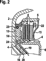
図2は、開放された状態のロックアップクラッチを示す、図1の部分図、
図3は、閉じられた又はスリップした状態のロックアップクラッチの、図1の部分図、
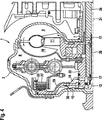
図4は、本発明の第2の解決策によるコンバータの断面図、
図5は、図4の一部、
図6は、本発明の第2の解決策による、連続的な補助壁の断面図、
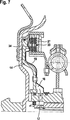
図7は、ばねエレメントとしての補助壁を有する、図6と同様の図である。
Claims (22)
- 自動車用のトルクコンバータ(1)であって、3チャンネル式オイルシステムとロックアップクラッチ(3)とを備えている形式のものにおいて、
ロックアップクラッチ(3)が、軸方向に摺動可能な少なくとも2つの薄片(4)を有しており、少なくとも1つの一方の薄片(4)が外側の薄片支持体(5)に相対回動不能に結合され、少なくとも1つの他方の薄片(4)が内側の薄片支持体(6)に相対回動不能に結合されており、
オイルシステムの第1の流路(7)が第1のチャンバ(8)に接続され、該第1のチャンバ(8)が、コンバータ(1)のハイドロダイナミックな構成部分としてのポンプ(9)、タービン(10)及び案内羽根車等を受容するようになっており、
コンバータ(1)の第2のチャンバ(13)がオイル圧力によって負荷され、それによってピストン(14)が薄片(4)に押し付けられることによって、第2の流路(12)がロックアップクラッチ(3)を操作するようになっており、
ピストンに対して間隔を保っている補助壁(19)が、第1のチャンバ(8)に向いた側のピストン(14)の側に取り付けられていて、これによってピストンと補助壁(19)との間にギャップ(20)が形成され、補助壁(19)がオイル密に、ピストン(14)に面した薄片(4)に当接し、それと同時に第1のチャンバ(8)及び第2のチャンバ(13)に対する液圧的な分離が形成され、またそれによって第3のチャンバ(16)が形成されるようになっており、
前記第3のチャンバ(16)が第3の流路(17)にオイル密に接続されている、
ことを特徴とする、トルクコンバータ。 - まず第1のチャンバ(8)、次いで第3のチャンバ(16)がオイルによって貫流されるようになっている、請求項1記載のトルクコンバータ。
- まず第3のチャンバ(16)、次いで第1のチャンバ(8)がオイルによって貫流されるようになっている、請求項1記載のトルクコンバータ。
- 第1のチャンバ(8)内に少なくとも1つのダンパ(18)が配置されている、請求項1から3までのいずれか1項記載のトルクコンバータ。
- 第1のチャンバ(8)に面した薄片(4)の歯列と、外側の薄片支持体(5)との間のオイル流が少なくとも減少されるように、シールエレメント(15)が取り付けられている、請求項1から4までのいずれか1項記載のトルクコンバータ。
- 前記シールエレメント(15)が環状のばねとして構成されている、請求項5記載のトルクコンバータ。
- 前記シールエレメント(15)が環状ディスクとして構成されていて、該環状ディスクが同時に、前記薄片(4)のための軸方向ストッパ(22)として用いられる、請求項5又は6記載のトルクコンバータ。
- 前記シールエレメント(15)が外側の薄片支持体(5)とオイル密に接続されている、請求項5から7までのいずれか1項記載のトルクコンバータ。
- 前記シールエレメント(5)がコンバータハウジング(2)とオイル密に接続されている、請求項5又は6記載のトルクコンバータ。
- シールエレメント(15)が溶接によって接続されている、請求項5から9までのいずれか1項記載のトルクコンバータ。
- シールエレメント(15)がかしめ接合によって結合されている、請求項5から9までのいずれか1項記載のトルクコンバータ。
- 補助壁(19)が部分的に隆起部を備えており、該隆起部がピストン(14)の組み付け後にピストン(14)上に載るようになっている、請求項1から11までのいずれか1項記載のトルクコンバータ。
- 第3のチャンバ(16)は、ピストン(14)が、少なくとも部分的に中空に構成されていて、それによって薄片(4)と第3の流路(17)との間のオイル流が可能である、請求項1から12までのいずれか1項記載のトルクコンバータ。
- 薄片(4)と、この薄片(4)上に配置された摩擦ライニングとが、終端薄片(27)の外側で、軸方向に配向された少なくとも1つの孔(33)を備えている、請求項1から4までのいずれか1項記載のトルクコンバータ。
- 前記孔(33)が摩擦ライニングの平均的な直径部上に配置されている、請求項14記載のトルクコンバータ。
- ピストン(14)とこのピストン(14)に面した薄片(4)との間のオイル流が薄片(4)の外径と孔(33)の外径との間の領域において少なくとも減少されるように、シールエレメント(15)が、ピストン(14)に面した薄片(4)とピストン(14)との間に設けられている、請求項14又は15までのいずれか1項記載のトルクコンバータ。
- シールエレメント(15)が円錐ベルト車として構成されている、請求項16記載のトルクコンバータ。
- 前記補助壁(19)が、ロックアップクラッチ(3)の外側の歯列領域まで構成されており、この領域内で前記孔(33)が補助壁(19)も貫通して延びており、それによってオイルがピストン(14)に形成された切欠(34)を介して第3のチャンバ(16)内に流入する、請求項14から16までのいずれか1項記載のトルクコンバータ。
- 補助壁(19)がディスク状のばねエレメントとして構成されている、請求項18記載のトルクコンバータ。
- 補助壁(19)が2つの部分(19a,19b)より成っている、請求項14から19までのいずれか1項記載のトルクコンバータ。
- 前記ピストン(14)のための回動防止部材(30)を備えており、
前記回動防止部材(30)が、ディスク状に有利には皿ばねとして構成されており、前記回動防止部材(30)がハウジング(2)にリベット留めされていて、前記回動防止部材(30)の半径方向外側のスリット内にピストン(14)のウエブ(32)が係合するようになっている、請求項1から20までのいずれか1項記載のトルクコンバータ。 - 前記回動防止部材(30)が同時に、ハウジング(2)とトランスミッション入力軸(29)との間の始動ディスク(摩耗防止手段)としても用いられるようになっている、請求項21記載のトルクコンバータ。
Applications Claiming Priority (5)
| Application Number | Priority Date | Filing Date | Title |
|---|---|---|---|
| US75830206P | 2006-01-12 | 2006-01-12 | |
| US60/758,302 | 2006-01-12 | ||
| DE102006055229 | 2006-11-21 | ||
| DE102006055229.6 | 2006-11-21 | ||
| PCT/DE2006/002317 WO2007079713A2 (de) | 2006-01-12 | 2006-12-27 | Wandler mit zwangs-ölführung |
Publications (3)
| Publication Number | Publication Date |
|---|---|
| JP2009523219A JP2009523219A (ja) | 2009-06-18 |
| JP2009523219A5 JP2009523219A5 (ja) | 2012-09-13 |
| JP5126067B2 true JP5126067B2 (ja) | 2013-01-23 |
Family
ID=46045580
Family Applications (1)
| Application Number | Title | Priority Date | Filing Date |
|---|---|---|---|
| JP2008549755A Expired - Fee Related JP5126067B2 (ja) | 2006-01-12 | 2006-12-27 | 強制オイルガイドを備えたコンバータ |
Country Status (6)
| Country | Link |
|---|---|
| EP (1) | EP1977141B2 (ja) |
| JP (1) | JP5126067B2 (ja) |
| CN (1) | CN101356389B (ja) |
| AT (1) | ATE449273T1 (ja) |
| DE (2) | DE112006003320B4 (ja) |
| WO (1) | WO2007079713A2 (ja) |
Families Citing this family (23)
| Publication number | Priority date | Publication date | Assignee | Title |
|---|---|---|---|---|
| DE102007005999A1 (de) | 2006-04-07 | 2007-10-11 | Zf Friedrichshafen Ag | Fluidbefüllte Kopplungsanordnung |
| DE102007052484B4 (de) * | 2006-11-29 | 2018-09-20 | Schaeffler Technologies AG & Co. KG | Drehmomentübertragungseinrichtung |
| DE112007002955A5 (de) * | 2006-12-27 | 2009-09-03 | Luk Lamellen Und Kupplungsbau Beteiligungs Kg | Kraftübertragungsvorrichtung |
| DE112007002931A5 (de) * | 2006-12-27 | 2009-09-10 | Luk Lamellen Und Kupplungsbau Beteiligungs Kg | Kraftübertragungsvorrichtung und Lagerscheibe, insbesondere Axialgleitlagerscheibe |
| DE102007014312A1 (de) | 2007-03-26 | 2008-10-02 | Zf Friedrichshafen Ag | Hydrodynamische Kopplungsvorrichtung |
| DE102008020683B4 (de) | 2007-05-09 | 2019-01-17 | Schaeffler Technologies AG & Co. KG | Drehmomentwandler mit Anordnung für Kühlfluidströmung und Anordnung zur Drehmomentübertragung auf einen Dämpfer |
| DE102008057657A1 (de) * | 2007-12-10 | 2009-06-18 | Luk Lamellen Und Kupplungsbau Beteiligungs Kg | Kraftübertragungsvorrichtung |
| DE102009024744B4 (de) | 2008-06-26 | 2023-02-16 | Schaeffler Technologies AG & Co. KG | Kraftübertragungsvorrichtung |
| DE102009051723A1 (de) | 2008-11-10 | 2010-05-12 | Luk Lamellen Und Kupplungsbau Beteiligungs Kg | Hydrodynamischer Drehmomentwandler mit Überbrückungskupplung |
| DE112009002706A5 (de) * | 2008-11-10 | 2013-06-13 | Schaeffler Technologies AG & Co. KG | Nasskupplung |
| JP5617806B2 (ja) * | 2011-09-29 | 2014-11-05 | アイシン・エィ・ダブリュ株式会社 | 流体伝達装置 |
| JP5609897B2 (ja) * | 2012-01-16 | 2014-10-22 | マツダ株式会社 | トルクコンバータ |
| DE102013208197A1 (de) | 2013-05-06 | 2014-11-06 | Schaeffler Technologies Gmbh & Co. Kg | Reibkupplung |
| DE102013222213A1 (de) * | 2013-10-31 | 2015-04-30 | Zf Friedrichshafen Ag | Schaltelement eines Automatgetriebes für Kraftfahrzeuge |
| WO2016118155A1 (en) * | 2015-01-23 | 2016-07-28 | Schaeffler Technologies AG & Co. KG | Impeller shell with thickended junction and method thereof |
| FR3053091B1 (fr) * | 2016-06-23 | 2019-12-20 | Valeo Embrayages | Embrayage hydrocinetique pour un vehicule automobile |
| CN110691926B (zh) * | 2017-03-10 | 2022-12-27 | 株式会社法雷奥凯佩科 | 具有居中的锁止离合器的液力扭矩耦合装置 |
| KR102069527B1 (ko) * | 2018-05-16 | 2020-01-23 | 주식회사 카펙발레오 | 차량용 토크 컨버터 |
| US11067157B2 (en) * | 2019-07-11 | 2021-07-20 | Schaeffler Technologies AG & Co. KG | Torque converter clutch system |
| DE102020208351A1 (de) | 2020-07-03 | 2022-01-05 | Zf Friedrichshafen Ag | Hydrodynamischer Drehmomentwandler |
| DE102020208352A1 (de) | 2020-07-03 | 2022-01-05 | Zf Friedrichshafen Ag | Hydrodynamischer Drehmomentwandler mit einer Torsionsdämpferwandung |
| DE102020212758A1 (de) | 2020-10-08 | 2022-04-14 | Volkswagen Aktiengesellschaft | Kupplung, insbesondere Doppelkupplung für ein Kraftfahrzeug |
| DE102020216031A1 (de) | 2020-12-16 | 2022-06-23 | Zf Friedrichshafen Ag | Hydrodynamischer Drehmomentwandler |
Family Cites Families (12)
| Publication number | Priority date | Publication date | Assignee | Title |
|---|---|---|---|---|
| JPH05126229A (ja) * | 1991-03-30 | 1993-05-21 | Aisin Seiki Co Ltd | ロツクアツプクラツチ付自動変速機のひきずり防止装置 |
| JP3854661B2 (ja) * | 1996-05-29 | 2006-12-06 | 株式会社エクセディ | ロックアップ装置付きトルクコンバータ |
| FR2762657B1 (fr) * | 1997-04-29 | 1999-05-28 | Valeo | Appareil d'accouplement hydrocinetique dote de moyens elastiques anti-bruit, notamment pour vehicule automobile |
| JP3715114B2 (ja) * | 1998-09-09 | 2005-11-09 | 株式会社エクセディ | トルクコンバータ |
| DE10117746B4 (de) † | 2000-04-28 | 2017-06-29 | Schaeffler Technologies AG & Co. KG | Drehmomentübertragungseinrichtung |
| FR2811049B1 (fr) * | 2000-06-29 | 2002-10-11 | Valeo | Appareil d'accouplement hydrocinetique, notamment pour vehicule automobile, comportant des moyens perfectionnes de liaison du piston au couvercle |
| DE10104346A1 (de) * | 2001-02-01 | 2002-08-08 | Zahnradfabrik Friedrichshafen | Hydrodynamischer Drehmomentwandler |
| FR2843433B1 (fr) * | 2002-08-06 | 2005-04-01 | Valeo Embrayages | Appareil d'accouplement hydrocinetique, notamment pour un vehicule automobile |
| JP2004116611A (ja) * | 2002-09-25 | 2004-04-15 | Exedy Corp | 流体式トルク伝達装置のロックアップ装置 |
| DE10350935B4 (de) * | 2002-11-16 | 2019-02-21 | Schaeffler Technologies AG & Co. KG | Drehmomentwandler |
| DE10314325B4 (de) * | 2003-03-28 | 2011-01-27 | Zf Friedrichshafen Ag | Hydrodynamischer Wandler mit einer Primärkupplung |
| DE102007005999A1 (de) * | 2006-04-07 | 2007-10-11 | Zf Friedrichshafen Ag | Fluidbefüllte Kopplungsanordnung |
-
2006
- 2006-12-27 CN CN2006800508811A patent/CN101356389B/zh not_active Expired - Fee Related
- 2006-12-27 EP EP06846948.5A patent/EP1977141B2/de not_active Not-in-force
- 2006-12-27 AT AT06846948T patent/ATE449273T1/de not_active IP Right Cessation
- 2006-12-27 DE DE112006003320T patent/DE112006003320B4/de not_active Expired - Fee Related
- 2006-12-27 DE DE202006020596U patent/DE202006020596U1/de not_active Expired - Lifetime
- 2006-12-27 WO PCT/DE2006/002317 patent/WO2007079713A2/de active Application Filing
- 2006-12-27 JP JP2008549755A patent/JP5126067B2/ja not_active Expired - Fee Related
Also Published As
| Publication number | Publication date |
|---|---|
| DE112006003320A5 (de) | 2008-09-18 |
| JP2009523219A (ja) | 2009-06-18 |
| EP1977141B2 (de) | 2014-01-01 |
| EP1977141B1 (de) | 2009-11-18 |
| CN101356389B (zh) | 2011-08-31 |
| DE202006020596U1 (de) | 2009-03-19 |
| WO2007079713A2 (de) | 2007-07-19 |
| ATE449273T1 (de) | 2009-12-15 |
| CN101356389A (zh) | 2009-01-28 |
| EP1977141A2 (de) | 2008-10-08 |
| DE112006003320B4 (de) | 2012-04-26 |
| WO2007079713A3 (de) | 2007-11-15 |
Similar Documents
| Publication | Publication Date | Title |
|---|---|---|
| JP5126067B2 (ja) | 強制オイルガイドを備えたコンバータ | |
| US7891473B2 (en) | Torque converter with forced oil circulation | |
| US7287630B2 (en) | Torque converter with lockup clutch | |
| US9121485B2 (en) | Torque converter with deflectable seal | |
| US7984800B2 (en) | Hydrodynamic clutch device | |
| JP4828291B2 (ja) | 流体式トルク伝達装置およびそれに用いられるロックアップ装置 | |
| JP2009523219A5 (ja) | ||
| JP6608317B2 (ja) | トルクコンバータのロックアップ装置 | |
| JP2017040361A5 (ja) | ||
| JP6206298B2 (ja) | クラッチ装置 | |
| US10697500B2 (en) | Two path sealed clutch | |
| JP2008138880A (ja) | トルク伝達装置 | |
| WO2016186125A1 (ja) | トルクコンバータのロックアップ装置 | |
| US10634228B2 (en) | Torque converter | |
| US8322501B2 (en) | Force transmission device | |
| JP2016217447A (ja) | トルクコンバータのロックアップ装置 | |
| JP2000192989A (ja) | 摩擦部材、ディスク組立体及びトルクコンバ―タ | |
| US20230081298A1 (en) | Flow channel structure and lock-up device | |
| US11519486B2 (en) | Hydrodynamic torque converter with a lock-up clutch | |
| CN111417792B (zh) | 由在两个套筒之间形成的通道供应流体的湿式离合器系统 | |
| JP2006153029A (ja) | 流体式トルク伝達装置のロックアップ装置 | |
| JP6473044B2 (ja) | トルクコンバータのロックアップ装置 | |
| JP5828862B2 (ja) | トルクコンバータ装置 | |
| WO2017029927A1 (ja) | トルクコンバータのロックアップ装置 | |
| WO2016163172A1 (ja) | 流体継手 |
Legal Events
| Date | Code | Title | Description |
|---|---|---|---|
| A621 | Written request for application examination |
Free format text: JAPANESE INTERMEDIATE CODE: A621 Effective date: 20091228 |
|
| RD04 | Notification of resignation of power of attorney |
Free format text: JAPANESE INTERMEDIATE CODE: A7424 Effective date: 20101227 |
|
| RD04 | Notification of resignation of power of attorney |
Free format text: JAPANESE INTERMEDIATE CODE: A7424 Effective date: 20101228 |
|
| A977 | Report on retrieval |
Free format text: JAPANESE INTERMEDIATE CODE: A971007 Effective date: 20120419 |
|
| A131 | Notification of reasons for refusal |
Free format text: JAPANESE INTERMEDIATE CODE: A131 Effective date: 20120426 |
|
| A524 | Written submission of copy of amendment under article 19 pct |
Free format text: JAPANESE INTERMEDIATE CODE: A524 Effective date: 20120725 |
|
| TRDD | Decision of grant or rejection written | ||
| A01 | Written decision to grant a patent or to grant a registration (utility model) |
Free format text: JAPANESE INTERMEDIATE CODE: A01 Effective date: 20120914 |
|
| A01 | Written decision to grant a patent or to grant a registration (utility model) |
Free format text: JAPANESE INTERMEDIATE CODE: A01 |
|
| A711 | Notification of change in applicant |
Free format text: JAPANESE INTERMEDIATE CODE: A711 Effective date: 20121010 |
|
| A61 | First payment of annual fees (during grant procedure) |
Free format text: JAPANESE INTERMEDIATE CODE: A61 Effective date: 20121015 |
|
| A521 | Request for written amendment filed |
Free format text: JAPANESE INTERMEDIATE CODE: A821 Effective date: 20121010 |
|
| R150 | Certificate of patent or registration of utility model |
Free format text: JAPANESE INTERMEDIATE CODE: R150 |
|
| FPAY | Renewal fee payment (event date is renewal date of database) |
Free format text: PAYMENT UNTIL: 20151109 Year of fee payment: 3 |
|
| S111 | Request for change of ownership or part of ownership |
Free format text: JAPANESE INTERMEDIATE CODE: R313111 |
|
| R350 | Written notification of registration of transfer |
Free format text: JAPANESE INTERMEDIATE CODE: R350 |
|
| R250 | Receipt of annual fees |
Free format text: JAPANESE INTERMEDIATE CODE: R250 |
|
| R250 | Receipt of annual fees |
Free format text: JAPANESE INTERMEDIATE CODE: R250 |
|
| R250 | Receipt of annual fees |
Free format text: JAPANESE INTERMEDIATE CODE: R250 |
|
| LAPS | Cancellation because of no payment of annual fees |