JP5056339B2 - Substrate gripping mechanism for substrate transfer equipment - Google Patents
Substrate gripping mechanism for substrate transfer equipment Download PDFInfo
- Publication number
- JP5056339B2 JP5056339B2 JP2007271093A JP2007271093A JP5056339B2 JP 5056339 B2 JP5056339 B2 JP 5056339B2 JP 2007271093 A JP2007271093 A JP 2007271093A JP 2007271093 A JP2007271093 A JP 2007271093A JP 5056339 B2 JP5056339 B2 JP 5056339B2
- Authority
- JP
- Japan
- Prior art keywords
- substrate
- gripping
- block
- lower block
- floating
- Prior art date
- Legal status (The legal status is an assumption and is not a legal conclusion. Google has not performed a legal analysis and makes no representation as to the accuracy of the status listed.)
- Expired - Fee Related
Links
Images


Description
本発明は、例えば液晶ディスプレイパネルやプラズマディスプレイパネルなどのフラットパネルディスプレイ用の基板の欠陥検査を行う基板検査装置などで、振動などによる上下変動無く安定して搬送するための搬送機構における基板把持機構に関するものである。 The present invention relates to a substrate gripping mechanism in a transport mechanism for stably transporting a substrate without a vertical fluctuation due to vibration or the like in a substrate inspection apparatus that performs defect inspection of a substrate for a flat panel display such as a liquid crystal display panel or a plasma display panel. It is about.
基板を搬送する方法としては、従来はローラを用いたコンベアによる方法が主に用いられ基板の搬送機構(チャッキング)は、基板裏面に直接ロール・コンベアーを接触させ搬送を行っていた。しかし、基板が大型化したことで、従来の方法にて搬送すると、例えば、搬送中の基板の重さのよる撓みや、搬送時の上下振動などにより、基板がローラに衝突してしまうことが原因として発生する搬送中の傷など、様々な問題が発生した。 Conventionally, as a method for transporting a substrate, a method using a conveyor using rollers is mainly used, and a substrate transport mechanism (chucking) transports a substrate by directly contacting a roll conveyor on the back surface of the substrate. However, due to the increase in size of the substrate, the substrate may collide with the rollers due to, for example, bending due to the weight of the substrate being transferred, vertical vibration during transfer, etc. Various problems occurred, such as scratches during transportation that occurred as a cause.
よって重さによる撓みや搬送中の上下振動が大きい大型基板に関してはローラを用いたコンベア搬送に替わり、全面をエアによって浮上させて搬送させる非接触による搬送技術が用いられてきている。 Therefore, for a large-sized substrate having large deflection due to weight and large vertical vibration during conveyance, a non-contact conveyance technique in which the entire surface is floated by air and conveyed is used instead of conveyor conveyance using rollers.
また、フラットパネルディスプレイでは、例えばカラーフィルタなどでは、製造工程において欠陥などの検査が行われているが、近年画面の高精細化が進み、それに伴って検査機自体も高性能なものが求められている。具体的には5μm以下の欠陥を検査するような、分解能が3μm以下の超高分解能カメラと用いた検査機が品質保証の点から必須となってきている。 In flat panel displays, for example, color filters are inspected for defects in the manufacturing process. However, in recent years, screens have become higher in definition, and accordingly, inspection machines themselves are required to have high performance. ing. Specifically, an inspection machine using an ultra-high resolution camera with a resolution of 3 μm or less that inspects defects of 5 μm or less has become essential from the viewpoint of quality assurance.
基板のエア浮上による搬送により基板検査する技術は、特許文献1〜3などにすでに記載されている。 Techniques for inspecting a substrate by conveying the substrate by air levitation have already been described in Patent Documents 1 to 3 and the like.
しかしながら、分解能が5μm以下の検査機用カメラは焦点深度が浅くまた、被写界深度も狭く、検査として撮像するためには、その被写界深度から外れないように安定した基板搬送が求められる。 However, an inspection machine camera with a resolution of 5 μm or less has a shallow depth of focus and a narrow depth of field, and in order to capture an image for inspection, stable substrate transport is required so as not to deviate from the depth of field. .
ローラによる基板搬送では接触搬送によりローラ自体の凹凸や設置状況などで、基板の搬送中の上下方向の変動が激しく、高分解能の検査用のカメラの被写界深度からはずれてしまう問題がある。また、上下変動による振動で、基板とローラとが衝突してしまい、基板を傷つけてしまう可能性がある。 In the substrate conveyance by the roller, there is a problem that the vertical fluctuation during the conveyance of the substrate is severe due to the unevenness of the roller itself and the installation condition due to the contact conveyance, and it is deviated from the depth of field of the high resolution inspection camera. In addition, the substrate and the roller may collide with each other due to vibration caused by vertical fluctuations, which may damage the substrate.
そこで、搬送面とは接触しない、エア浮上に搬送が行われるようになった。当初の非接触にエア搬送技術は基板をエアの吹き出しにより基板を浮かせるだけであったので、基板の浮上精度むらが大きく、搬送中の浮上むらから発生する上下変動が起きてしまい、それによる搬送部との接触などの傷の問題や、振動による上下変動により検査面が検査用カメラの被写界深度からはずれてしまう問題があった。そこで、基板の浮上に関して、エアの吹き出しと同時に吸い込みも行うことで、浮上の上下変動をエアの吸い込み力によって抑える技術が開発された。この技術により高精度浮上のものに関しては、搬送時の浮上むらが、10μm以下まで抑えられるようになり、安定した基板搬送が出来るようになった。これにより検査面の被写界深度内から外れずに搬送することも可能となり、また搬送面との衝突も解消された。 Therefore, the conveyance is performed in the air levitation that does not contact the conveyance surface. In the first non-contact air transfer technology, the substrate was only floated by blowing air, so the floating accuracy of the substrate was large, and the vertical fluctuation caused by the floating unevenness during transfer occurred, and the transfer by that There is a problem of scratches such as contact with the part, and a problem that the inspection surface deviates from the depth of field of the inspection camera due to vertical fluctuation due to vibration. Therefore, a technology has been developed to suppress the vertical fluctuation of the flying height by the air sucking force by performing air sucking and sucking in relation to the substrate floating. With this technology, the non-uniformity of the floating during transportation can be suppressed to 10 μm or less with respect to the highly precise floating, and stable substrate transportation can be performed. As a result, the inspection surface can be transported without departing from the depth of field, and the collision with the transport surface is eliminated.
上記の技術にて、エア搬送による浮上ムラは解消され、安定した浮上精度にて基板を浮上させることが可能になった。 With the above-described technology, the flying unevenness due to air conveyance is eliminated, and the substrate can be lifted with a stable flying accuracy.
エア搬送により高精度浮上が可能になったが、ローラやコンベアを使用しないため、基板を移動させる手段が必要となる。従来の方法では、基板外側にコンベア等の駆動部を設けコンベアに吸盤やチャッキング用ハンドを設置する例もある。しかし、搬送機構側が基準となるため、搬送側機構チャッキング高さが変動した場合基板高さに影響する。そのために搬送機構側の駆動部精度及び、吸着パットやチャッキング用ハンド取り付け精度が必要になる。 Although high-accuracy levitation can be achieved by air conveyance, a means for moving the substrate is required because rollers and conveyors are not used. In the conventional method, there is an example in which a driving unit such as a conveyor is provided outside the substrate and a suction cup or a chucking hand is installed on the conveyor. However, since the transport mechanism side is a reference, if the transport mechanism chucking height fluctuates, the substrate height is affected. For this purpose, the drive unit accuracy on the transport mechanism side and the suction pad and chucking hand mounting accuracy are required.
また、エア搬送では基板の重さにより浮上高さも変動するため、基板の重さが変わる都度、搬送機構側の吸着パットやチャッキング用ハンドの高さ調整が必要となる。 In addition, since the flying height varies depending on the weight of the substrate in the air conveyance, it is necessary to adjust the height of the suction pad and the chucking hand on the conveyance mechanism side whenever the weight of the substrate changes.
更に、エア搬送用浮上機構は、浮上精度(精密級・並級)により価格が高価な物があるため、使用条件により使い分ける必要があり、組み合わせ(並級→精密級→並級)及び隙間により浮上高さに変動が発生する。 In addition, the air transport levitation mechanism is expensive due to the levitation accuracy (precise grade / normal grade), so it is necessary to use it depending on the usage conditions. Depending on the combination (normal grade → precision grade → normal grade) and clearance Variations in flying height occur.
そこで本発明は、エア搬送にて可能となった高精度浮上を確保しながら基板搬送を可能にするための搬送機構を供給することを目的とする。
Accordingly, an object of the present invention is to provide a transport mechanism for enabling substrate transport while ensuring high-accuracy levitation made possible by air transport.
請求項1によれば、基板搬送部に設置された基板を浮上させる基板浮上機構と、前記基板の片端部もしくは両端部を把持する把持手段と、前記把持手段を移動させる把持搬送手段を備えたことを特徴とする基板搬送装置において、
前記把持手段は、基板端部を基板挟み部により挟み込む上ブロックおよび下ブロックと、
前記上ブロックおよび下ブロックを支えかつ移動軸をそろえるための支柱と、
前記上ブロックと下ブロックの基板挟み部の外側に配置されるチャック開閉チューブと、
前記チャック開閉チューブ内部に流体を給排する流体給排手段と、
前記上ブロックと下ブロックの間に配置される反発ばねと、
前記上ブロックおよび下ブロックを支える支え梁および支えばねと、を備え、
前記チャック開閉チューブ内部に流体を供給して前記チャック開閉チューブを膨らませると前記上ブロックおよび前記下ブロックの基板挟み部は基板端部を挟み込む動作を行い、前記チャック開閉チューブ内部から流体を排出すると前記反発ばねにより前記上ブロックおよび前記下ブロックの基板挟み部の間に間隙が形成されて基板端部を開放する動作を行うものであり、
少なくとも1以上の前記把持手段を往復運動させる前記把持搬送手段を備えることを特徴とする基板搬送装置用把持機構である。
According to the first aspect of the present invention, the apparatus includes the substrate floating mechanism that floats the substrate installed in the substrate transport unit, the gripping unit that grips one or both ends of the substrate, and the gripping transport unit that moves the gripping unit. In the substrate transfer device characterized in that
The gripping means includes an upper block and a lower block that sandwich a substrate end portion by a substrate sandwiching portion;
A support for supporting the upper block and the lower block and aligning the movement axis;
A chuck opening and closing tube disposed outside the substrate sandwiching portion of the upper block and the lower block;
Fluid supply / discharge means for supplying and discharging fluid to and from the chuck opening and closing tube;
A repulsion spring disposed between the upper block and the lower block;
A support beam and a support spring that support the upper block and the lower block,
When a fluid is supplied to the inside of the chuck opening / closing tube to expand the chuck opening / closing tube, the substrate sandwiching portions of the upper block and the lower block operate to sandwich the substrate end, and when the fluid is discharged from the inside of the chuck opening / closing tube A gap is formed between the substrate sandwiching portions of the upper block and the lower block by the repulsion spring to perform an operation of opening the substrate end.
A gripping mechanism for a substrate transport apparatus, comprising the gripping and transporting means for reciprocating at least one gripping means.
請求項2によれば、前記基板把持手段の上ブロックと下ブロックのいずれかの基板挟み部に吸着部を配置したことを特徴とする請求項1記載の基板搬送装置用把持機構である。 According to a second aspect of the present invention, in the substrate transport apparatus gripping mechanism according to the first aspect of the present invention, an adsorbing portion is disposed in either of the upper and lower blocks of the substrate gripping means.
請求項1に係わる発明によれば、搬送対象の基板仕様(重さや厚み)の変更により、基板浮上高さが変動した場合でも、把持機構のチャッキング高さの調整が必要なく、基板をチャックしたときに基板基準にて調整を行うことが可能である。また、基板の浮上高さの変動にチャッキング後でも追従することが可能である。 According to the first aspect of the present invention, even when the floating height of the substrate fluctuates due to changes in the substrate specifications (weight and thickness) to be transferred, the chucking height of the gripping mechanism does not need to be adjusted and the substrate is chucked. Adjustment can be performed on the basis of the substrate. Further, it is possible to follow the fluctuation of the flying height of the substrate even after chucking.
請求項2に係わる発明によれば、基板把持手段の上ブロックと下ブロックのいずれかの基板挟み部に吸着部を配置することにより、基板の把持安定を図ることが可能となる。 According to the second aspect of the present invention, it is possible to stabilize the holding of the substrate by disposing the adsorbing portion on the substrate holding portion of either the upper block or the lower block of the substrate holding means.
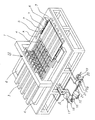
以下、本発明の1実施形態である基板搬送装置における基板把持機構について図面に基づいて説明する。図1は基板の検査装置に適用した基板搬送装置の構成図である。 Hereinafter, a substrate gripping mechanism in a substrate transfer apparatus according to an embodiment of the present invention will be described with reference to the drawings. FIG. 1 is a configuration diagram of a substrate transfer device applied to a substrate inspection apparatus.
本発明に係る基板搬送装置1は、空気の吹き出しにて基板2を浮上させながら搬送する浮上機構3と、空気の吹き出しおよび吸引によって基板2を精密浮上させながら搬送する浮上機構4と、前記基板浮上機構3及び基板浮上機構4の側面からはみ出した前記基板2の片端部及び両端部を固定する基板把持機構5と、前記基板浮上機構3及び基板浮上機構4側面と隣接して設けられ、前記基板固定機構5を介して前記基板2を搬送方向Xに沿った方向に搬送する基板搬送機構6と、前記基板浮上機構3および前記基板保持機構4への空気の供給および前記基板浮上機構4からの空気の吸引を行う浮上制御部Aと、前記基板2の表面検査を行う検査部Bを備える。
The substrate transport apparatus 1 according to the present invention includes a levitation mechanism 3 that transports the
次に前記基板浮上機構3および前記基板浮上機構4の構造について図2を使用して説明する。なお、図2は前記基板浮上機構3および前記基板浮上機構4の断面模式図であり、理解を容易にするために基板2の厚みおよび浮上量を誇張している。
Next, the structure of the substrate floating mechanism 3 and the substrate
本発明の基板搬送装置1における前記基板浮上機構4は、矩形状の中空構造体であり、基板2と対向する表面3aおよび4aは無数の微細な孔の空いた板状の物質(例えば、多孔質カーボンや金属焼結体など)で形成されている。この表面3aおよび4aは内部の中空空間10および12と隣接されており、この中空空間10および12に接続されている配管10p、12pを通じて前記浮上制御部Aから圧力を与えることによって、表面3aおよび4aの全域に均一な上向きの空気流13および14を形成する事ができる。この上向きの空気流によって基板2をわずかに浮上させる事が可能となる。
The
また前記基板浮上機構4において、域以外の表面4aには、10〜50mm程度の範囲で等間隔もしくは不規則な間隔で直径0.5〜2mm程度の吸引穴8が全域に設けられている。この吸引穴8は基板浮上機構3の内部に設けられた前記中空空間10とは導通しておらず、別に設けられた中空空間11と接続されており、前記浮上制御部Aによって配管11vを通じて中空空間11の内圧を下げることにより、前記吸引穴8から空気を吸い込む事ができる。
In the
そして前記表面4a全域から空気を吹き出すと同時に、前記吸引穴8からも空気の吸い込みを行うことにより、前記基板2の浮上量を高い精度で維持する事が可能となる。
By blowing air from the entire area of the surface 4a and simultaneously sucking air from the
本発明の基板把持機構5は、このような基板浮上機構4上で浮上した状態の基板を、所定の方向へ移動させるために、基板2の片側もしくは両側の端部を把持するものであるが、比較のため、まず従来の基板把持機構の技術について図3及び図4を用いて説明する。
The
図3に従来方式の基板把持機構を記す。コロロール(コンベア)等による搬送は、コロロール自体が回転し基板を搬送している。そのため、基板の保持は基板把持ピン25にて基板端面を挟むようにする。送りはコンベアにより行い、基板把持ピン25は補助及び位置出しとして使用する。
FIG. 3 shows a conventional substrate gripping mechanism. In the conveyance by a roller roll (conveyor) or the like, the roller roll itself rotates to convey the substrate. Therefore, the substrate is held by holding the substrate end surface with the
図4に従来方式の基板把持機構の詳細を記す。ベースプレート24に設置された基板把持ピン25は、図4(A)に示す基板投入時では基板2には触れておらず、図4(B)に示すアライメント後にピン25が基板2方向に移動し、基板を固定する。この方法は基板2上下面からの把持は行わずあくまでもコロ搬送の補助の役割を行う
FIG. 4 shows details of a conventional substrate gripping mechanism. The
次に、本発明の基板搬送装置1における基板把持機構5の構造について図5を使用し説明する。図5は、基板把持機構5を図1において基板2の幅方向に切った断面図である。
Next, the structure of the
基板把持機構5は上ブロック26、下ブロック27、反発スプリング28、チャック部開閉用チューブ29、支柱30にて構成されている。支柱30は、上ブロック26および下ブロック27を、その基板把持のための駆動方向をそろえられるように支えている。
The substrate
チャック部開閉用チューブ29には図示せぬ流体給排手段が接続されており、チャック部開閉用チューブ29内部に流体を供給または排出する。チューブ1内部へ供給される流体としては、各種の気体や液体を選ぶことができる。
A fluid supply / discharge means (not shown) is connected to the chuck portion opening /
このようにチャック部開閉用チューブ29は、その内部に流体を供給すると直径方向に膨らみ、その内部から流体を排出すると直径方向に押しつぶされたような形状となる。チャック部開閉用チューブ29が膨らんだとき、上ブロック26と下ブロック27の基板挟み部は基板2を把持することができ(基板チャック状態)、その把持力はチャック開閉用チューブ29内部の空気圧力と反発スプリング28の力により決まる。
In this way, the chuck portion opening /
チャック部開閉用チューブ29内部から流体を排出したとき、上ブロック26と下ブロック27の基板挟み部の間には、反発スプリング28の力により間隙ができ、基板2を把持せず解放することができる(基板アンチャック状態)。
When the fluid is discharged from the inside of the chuck opening /
図5(A)は、把持機構単体の場合を示す。このとき、アンチャック状態では上ブロック26と下ブロック27は基板2に対して均等に開くが、基板2をチャックした状態では把持機構部自重により、チャック位置が下方に下がってしまうことがある。したがって基板2浮上位置と把持機構5の高さ位置がずれてしまい、基板2にたわみが発生する可能性がある。
FIG. 5A shows the case of the gripping mechanism alone. At this time, the
そこで、図5(B)に示す本願発明の把持機構では、把持機構5の自重をキャンセルするために、支え梁40および支えスプリング31を設置し、基板2をチャッキング後も基板2高さに追従することが可能としたものである。
Therefore, in the gripping mechanism of the present invention shown in FIG. 5B, in order to cancel the weight of the
図5(B)に示す本願発明の把持機構の動作は次のようなものである。
アンチャック状態から、チューブ29に圧縮空気を入れるとチューブ29が膨らみ、上ブロック26が下に、下ブロック27が上に移動し、基板2をチャックするようになっている。
The operation of the gripping mechanism of the present invention shown in FIG. 5 (B) is as follows.
When compressed air is introduced into the
スプリング31は、支柱30から延びている支え梁40に設置した固定用ボルトに通して配置し、更に下ブロック27に設けた雌ネジにボルトで固定する。上下ブロック26、27の自重は、固定用ボルトからスプリング31に荷重が伝わりスプリングの戻ろうとする力により持ち上げられる。その持ち上がる量は、固定用ボルトの押し込み量(スプリング31の潰量)により調整することができる。
The
ここで、スプリング31の押し込み量を調整しておくことにより、上下ブロック26、27の重さとの吊り合いにより、チャック時の位置(チャック位置高さ)を調整することができ、なおかつ上下ブロック26、27の自重をキャンセルすることと同じになり、基板2に上下ブロック26、27の重さが掛からないため、基板2の上下移動に対し追従することが可能になる。
Here, by adjusting the pushing amount of the
また、図5(C)に示す本願発明の把持機構では、把持機構5の自重をキャンセルするための支えスプリングとして、定荷重巻きばね32を使用している。定荷重巻きばね32は、巻きばねの伸び縮みに関係なく一定の荷重を得ることが可能なばねであるので、常に一定の力で把持機構5を支えることが可能である。
Further, in the gripping mechanism of the present invention shown in FIG. 5C, a constant
更に、図5(D)に示すように、下ブロック27に吸着部34を設置することにより、基板2の把持安定を行うことも可能である。
Furthermore, as shown in FIG. 5D, it is possible to stabilize the holding of the
以上で説明した本発明の基板把持機構5は、基板2の片側もしくは両側の端部を、基板2の上下面より挟み込んで固定しており、さらに、基板2に垂直な方向に移動自在なフローティング構造を介して基板搬送機構6の稼動部分であるベースプレート7に2個所以上設置されている(図1参照)。これにより搬送中の基板2の垂直方向位置と基板搬送機構6の垂直方向位置とのずれを吸収することが可能となり、基板2を高精度に搬送することができる。
In the
本発明の基板搬送装置1における基板搬送機構6は、図1に示すように、基板浮上機構3の片側もしくは両側に隣接して設けられ、基板搬送方向Xに沿って基板2をムラ無く一定速度で搬送する一軸の搬送機構である。例えば、サーボモーターとボールネジの組み合わせに比べ速度変動の小さなリニアモーターとリニアガイドの組み合わせが適している。しかしながら今後検査の要求精度が上がり超高分解能の検査機等に本搬送装置を適用させる場合などは、コアレスタイプのリニアモーターにエア浮上ガイド等を組み合わせいくことも考えられる。
As shown in FIG. 1, the substrate transfer mechanism 6 in the substrate transfer apparatus 1 of the present invention is provided adjacent to one side or both sides of the substrate floating mechanism 3 and moves the
本発明の基板搬送装置1における前記浮上制御部Aは、図1に示すように、基板浮上機構3及び基板浮上機構4へ圧縮空気を供給する圧空経路21と、基板浮上機構4から空気を吸引排気する排気経路18を備える。なお、図1において前記浮上制御部Aは説明のために基板搬送装置1の機側空間に配置されているが、実際には基板搬送装置1の下、もしくは別体の筐体に収まる。
As shown in FIG. 1, the levitation controller A in the substrate transfer apparatus 1 of the present invention sucks air from the substrate levitation mechanism 3 and the
前記圧空経路21の上流側には供給圧力を調整する圧力調整弁19と、配管を分岐して基板浮上機構3と基盤浮上機構4に圧空を分配供給するマニホールド20を備える。また前記排気経路18の上流側には空気吸引の動力源となるブロアーポンプ15と、吸い込み流量および圧力を調整するボールバルブ16が具備されている。供給圧力および吸い込み流量を調整することにより、基板浮上機構4搬送面の基板2の浮上精度を高める事が可能となる。
On the upstream side of the
本発明の基板搬送装置1における検査部Bは、図1に示すように、基板搬送機構6、基板浮上機構3および基板浮上機構4を搬送方向Xに垂直な幅方向に跨ぐように設置された梁状部材によって基板浮上機構4の上面より所定の高さ位置に設けられ、基板2の上面を撮像するカメラ装置22と、図示しない取り付け部材によって基板浮上機構4の上面よりも下方に設けられ、前記カメラ装置22の導光方向に光を照射する光源9を備える。また、カメラ装置22は搬送面に垂直な方向の位置調整および搬送方向Xと平行な回転軸周りの角度調整自在なアライメントステージを介して梁状部材に固定されている。
As shown in FIG. 1, the inspection unit B in the substrate transport apparatus 1 of the present invention is installed so as to straddle the substrate transport mechanism 6, the substrate floating mechanism 3, and the
最後に図6を用いて、搬送中の基板2の具体的な浮上状態を説明する。図6は説明のため、基板2の厚さおよび基板浮上機構3、基板浮上機構4とのギャップを誇張して表現している。
Finally, a specific floating state of the
まず図6(a)に示すように、基板浮上機構3の領域上を基板2が浮上搬送されてくる。次に図6(b)に示すように、基板浮上機構4領域に達した基板2の先端部は、基板浮上機構3からの空気の吹き上げと基板浮上機構4による吸着効果により浮上量が大きくなる。実際には基板2の先端部が下方に極わずかに撓んだ状態となる。
First, as shown in FIG. 6A, the
このように、基板浮上機構3と基板浮上機構4の間の乗り継ぎによる高さ変動は、従来方法の基板把持機構では吸収することができず、基板2に撓みが発生する。撓みは高精度検査においては無視できない影響を及ぼすため、検査を正常に行うことができなくなる。しかし本願発明の基板把持機構によれば、基板2の浮上量変動にうまく追随しつつ搬送が可能であるため、高精度な検査も問題なく実施することが可能である。
Thus, the height fluctuation due to the connection between the substrate floating mechanism 3 and the
1… 基板搬送装置
2… 基板
3… 基板浮上機構
3a… 表面(基板浮上機構)
4… 基板浮上機構
4a… 表面(基板浮上機構)
5… 基板把持機構
6… 基板搬送機構
7… ベースプレート
8… 吸引穴(基板浮上機構)
9… 透過検査用照明
10… 中空空間(基板浮上機構:吹き上げ)
10p… 配管(基板浮上機構:吹き上げ)
11… 中空空間(基板浮上機構:吸引)
11v… 配管(基板浮上機構:吸引)
12… 中空空間(基材浮上機構:吹き上げ)
12p… 配管(基材浮上機構:吹き上げ)
13… 空気流(基板浮上機構:吹き上げ)
14… 空気流(基板浮上機構:吹き上げ)
15… ブロアーポンプ(吸引)
16… ボールバルブ
17… チャンバー
18… 排気経路
19… 圧力調整弁
20… マニホールド
21… 圧空経路
22… カメラ装置
23… コロロール(搬送用)
24… ベースプレート
25… 基板把持ピン
26… 上ブロック
27… 下ブロック
28… 反発スプリング
29… チャック開閉用チューブ
30… 支柱
31… 支えスプリング
32… 定荷重巻きスプリング
33… 排気圧
34… 吸着部
40… 支え梁
DESCRIPTION OF SYMBOLS 1 ...
4 ... Substrate levitation mechanism 4a ... Surface (substrate levitation mechanism)
5 ... Substrate gripping mechanism 6 ... Substrate transport mechanism 7 ...
9. Illumination for
10p ... Piping (substrate floating mechanism: blowing up)
11 ... Hollow space (substrate floating mechanism: suction)
11v ... Piping (substrate floating mechanism: suction)
12 ... Hollow space (base floating mechanism: blowing up)
12p ... Piping (base levitation mechanism: blowing up)
13 ... Air flow (substrate floating mechanism: blowing up)
14 ... Air flow (substrate floating mechanism: blowing up)
15 ... Blower pump (suction)
16 ...
24 ...
Claims (2)
前記把持手段は、基板端部を基板挟み部により挟み込む上ブロックおよび下ブロックと、
前記上ブロックおよび下ブロックを支えかつ移動軸をそろえるための支柱と、
前記上ブロックと下ブロックの基板挟み部の外側に配置されるチャック開閉チューブと、
前記チャック開閉チューブ内部に流体を給排する流体給排手段と、
前記上ブロックと下ブロックの間に配置される反発ばねと、
前記上ブロックおよび下ブロックを支える支え梁および支えばねと、を備え、
前記チャック開閉チューブ内部に流体を供給して前記チャック開閉チューブを膨らませると前記上ブロックおよび前記下ブロックの基板挟み部は基板端部を挟み込む動作を行い、前記チャック開閉チューブ内部から流体を排出すると前記反発ばねにより前記上ブロックおよび前記下ブロックの基板挟み部の間に間隙が形成されて基板端部を開放する動作を行うものであり、
少なくとも1以上の前記把持手段を往復運動させる前記把持搬送手段を備えることを特徴とする基板搬送装置用把持機構。 A substrate transportation system comprising: a substrate floating mechanism that floats a substrate installed in the substrate transportation unit; a gripping unit that grips one or both ends of the substrate; and a gripping transport unit that moves the gripping unit. In the device
The gripping means includes an upper block and a lower block that sandwich a substrate end portion by a substrate sandwiching portion;
A support for supporting the upper block and the lower block and aligning the movement axis;
A chuck opening and closing tube disposed outside the substrate sandwiching portion of the upper block and the lower block;
Fluid supply / discharge means for supplying and discharging fluid to and from the chuck opening and closing tube;
A repulsion spring disposed between the upper block and the lower block;
A support beam and a support spring that support the upper block and the lower block,
When a fluid is supplied to the inside of the chuck opening / closing tube to expand the chuck opening / closing tube, the substrate sandwiching portions of the upper block and the lower block operate to sandwich the substrate end, and when the fluid is discharged from the inside of the chuck opening / closing tube A gap is formed between the substrate sandwiching portions of the upper block and the lower block by the repulsion spring to perform an operation of opening the substrate end.
A holding mechanism for a substrate transfer apparatus, comprising: the holding and transferring means for reciprocating at least one of the holding means.
2. The gripping mechanism for a substrate transport apparatus according to claim 1, wherein a suction part is arranged in either of the upper and lower blocks of the substrate gripping means.
Priority Applications (1)
| Application Number | Priority Date | Filing Date | Title |
|---|---|---|---|
| JP2007271093A JP5056339B2 (en) | 2007-10-18 | 2007-10-18 | Substrate gripping mechanism for substrate transfer equipment |
Applications Claiming Priority (1)
| Application Number | Priority Date | Filing Date | Title |
|---|---|---|---|
| JP2007271093A JP5056339B2 (en) | 2007-10-18 | 2007-10-18 | Substrate gripping mechanism for substrate transfer equipment |
Publications (2)
| Publication Number | Publication Date |
|---|---|
| JP2009098052A JP2009098052A (en) | 2009-05-07 |
| JP5056339B2 true JP5056339B2 (en) | 2012-10-24 |
Family
ID=40701192
Family Applications (1)
| Application Number | Title | Priority Date | Filing Date |
|---|---|---|---|
| JP2007271093A Expired - Fee Related JP5056339B2 (en) | 2007-10-18 | 2007-10-18 | Substrate gripping mechanism for substrate transfer equipment |
Country Status (1)
| Country | Link |
|---|---|
| JP (1) | JP5056339B2 (en) |
Cited By (3)
| Publication number | Priority date | Publication date | Assignee | Title |
|---|---|---|---|---|
| CN107381056A (en) * | 2017-09-05 | 2017-11-24 | 滁州克莱帝玻璃科技有限公司 | A kind of glass partition production conveying device |
| KR102231462B1 (en) * | 2019-09-25 | 2021-03-24 | 주식회사 나노프로텍 | Non-contact Type Transferming apparatus for A Cell Phone Cover Grass |
| KR102267705B1 (en) * | 2020-09-17 | 2021-06-22 | 주식회사 티에스아이코리아 | Inspection apparatus for chip on film |
Families Citing this family (14)
| Publication number | Priority date | Publication date | Assignee | Title |
|---|---|---|---|---|
| JP2009231717A (en) * | 2008-03-25 | 2009-10-08 | Toppan Printing Co Ltd | Substrate moving apparatus, substrate carrying apparatus and substrate imaging apparatus |
| JP2011026093A (en) * | 2009-07-28 | 2011-02-10 | Kataoka Seisakusho:Kk | Substrate transfer device |
| KR101185532B1 (en) * | 2009-12-30 | 2012-09-25 | 엘아이지에이디피 주식회사 | Apparatus for transferring substrate and method using thereof |
| US8598538B2 (en) * | 2010-09-07 | 2013-12-03 | Nikon Corporation | Movable body apparatus, object processing device, exposure apparatus, flat-panel display manufacturing method, and device manufacturing method |
| US20120064460A1 (en) * | 2010-09-07 | 2012-03-15 | Nikon Corporation | Movable body apparatus, object processing device, exposure apparatus, flat-panel display manufacturing method, and device manufacturing method |
| JP2012073036A (en) * | 2010-09-27 | 2012-04-12 | Hitachi High-Technologies Corp | Glass substrate defect checkup device and glass substrate defect checkup method |
| JP5943799B2 (en) * | 2012-09-28 | 2016-07-05 | AvanStrate株式会社 | Glass substrate transfer apparatus and glass substrate manufacturing method |
| JP2014123769A (en) * | 2014-03-06 | 2014-07-03 | Tokyo Ohka Kogyo Co Ltd | Ultraviolet irradiation device and ultraviolet irradiation method |
| KR101534180B1 (en) * | 2014-04-25 | 2015-07-07 | 지티엔이(주) | The apparatus for transferring the glass substrate and the method therefor |
| JP6803654B2 (en) * | 2015-07-07 | 2020-12-23 | 東朋テクノロジー株式会社 | Glass substrate inspection equipment |
| KR102134271B1 (en) * | 2018-04-25 | 2020-07-15 | 세메스 주식회사 | Apparatus for processing substrate |
| KR102215123B1 (en) * | 2018-11-26 | 2021-02-16 | 주식회사 탑 엔지니어링 | Apparatus and method for inspecting surface of substrate |
| KR102134274B1 (en) * | 2020-03-10 | 2020-07-15 | 세메스 주식회사 | Apparatus for processing substrate |
| CN115791836B (en) * | 2023-01-12 | 2023-05-02 | 广州讯中信息科技有限公司 | Display screen detection device and display screen detection method |
Family Cites Families (5)
| Publication number | Priority date | Publication date | Assignee | Title |
|---|---|---|---|---|
| JP2000009661A (en) * | 1998-06-26 | 2000-01-14 | Ntn Corp | Flat panel inspection device |
| JP2000059007A (en) * | 1998-08-14 | 2000-02-25 | Toyo Commun Equip Co Ltd | Warpage correcting mechanism for printed substrate in reflow device |
| JP2003302346A (en) * | 2002-04-12 | 2003-10-24 | Hitachi Electronics Eng Co Ltd | Surface inspection device for sheet work |
| TWI226303B (en) * | 2002-04-18 | 2005-01-11 | Olympus Corp | Substrate carrying device |
| JP3815687B1 (en) * | 2005-03-09 | 2006-08-30 | 株式会社 シーズ | Clamp unit for substrate transfer |
-
2007
- 2007-10-18 JP JP2007271093A patent/JP5056339B2/en not_active Expired - Fee Related
Cited By (3)
| Publication number | Priority date | Publication date | Assignee | Title |
|---|---|---|---|---|
| CN107381056A (en) * | 2017-09-05 | 2017-11-24 | 滁州克莱帝玻璃科技有限公司 | A kind of glass partition production conveying device |
| KR102231462B1 (en) * | 2019-09-25 | 2021-03-24 | 주식회사 나노프로텍 | Non-contact Type Transferming apparatus for A Cell Phone Cover Grass |
| KR102267705B1 (en) * | 2020-09-17 | 2021-06-22 | 주식회사 티에스아이코리아 | Inspection apparatus for chip on film |
Also Published As
| Publication number | Publication date |
|---|---|
| JP2009098052A (en) | 2009-05-07 |
Similar Documents
| Publication | Publication Date | Title |
|---|---|---|
| JP5056339B2 (en) | Substrate gripping mechanism for substrate transfer equipment | |
| JP5092627B2 (en) | Substrate transfer device and substrate inspection device | |
| KR101344869B1 (en) | High precision gas bearing split-axis stage for transport and constraint of large flat flexible media during processing | |
| JP4624236B2 (en) | Alignment equipment for vacuum deposition | |
| US20070195653A1 (en) | Non-contact support platforms for distance adjustment | |
| JP6023440B2 (en) | Coating device | |
| WO2016159062A1 (en) | Object conveyance apparatus, exposure apparatus, flat panel display production method, device production method, object conveyance method, and exposure method | |
| JP4418428B2 (en) | Substrate floating device | |
| JP2008166348A (en) | Substrate transfer apparatus | |
| TWI743614B (en) | Substrate processing device and substrate processing method | |
| CN101144920A (en) | Substrate detecting device | |
| JP2012094770A (en) | Inspection device and substrate positioning method | |
| KR102605917B1 (en) | Scribing apparatus | |
| CN108701635B (en) | Substrate floating and conveying device | |
| JP5176631B2 (en) | Substrate transfer device and substrate inspection device | |
| TWI389240B (en) | The support of the workpiece | |
| JP4982292B2 (en) | Coating apparatus and coating method | |
| WO2013150787A1 (en) | Object transfer system, exposure apparatus, method for manufacturing flat panel display, device manufacturing method, object holding apparatus, object transfer apparatus, object transfer method, and object replacing method | |
| JP2007250871A (en) | Substrate transport apparatus | |
| JP2010034382A (en) | Substrate transport apparatus and substrate imaging pickup apparatus | |
| CN107265838B (en) | Scribing equipment | |
| KR101793021B1 (en) | Substrate transportation device | |
| KR102353206B1 (en) | Scribing apparatus | |
| JP2009231717A (en) | Substrate moving apparatus, substrate carrying apparatus and substrate imaging apparatus | |
| JP2004241465A (en) | Work position correcting apparatus and cassette transporting apparatus |
Legal Events
| Date | Code | Title | Description |
|---|---|---|---|
| A621 | Written request for application examination |
Free format text: JAPANESE INTERMEDIATE CODE: A621 Effective date: 20100921 |
|
| A521 | Written amendment |
Free format text: JAPANESE INTERMEDIATE CODE: A523 Effective date: 20110915 |
|
| A977 | Report on retrieval |
Free format text: JAPANESE INTERMEDIATE CODE: A971007 Effective date: 20120321 |
|
| A131 | Notification of reasons for refusal |
Free format text: JAPANESE INTERMEDIATE CODE: A131 Effective date: 20120410 |
|
| A521 | Written amendment |
Free format text: JAPANESE INTERMEDIATE CODE: A523 Effective date: 20120608 |
|
| TRDD | Decision of grant or rejection written | ||
| A01 | Written decision to grant a patent or to grant a registration (utility model) |
Free format text: JAPANESE INTERMEDIATE CODE: A01 Effective date: 20120703 |
|
| A01 | Written decision to grant a patent or to grant a registration (utility model) |
Free format text: JAPANESE INTERMEDIATE CODE: A01 |
|
| A61 | First payment of annual fees (during grant procedure) |
Free format text: JAPANESE INTERMEDIATE CODE: A61 Effective date: 20120716 |
|
| FPAY | Renewal fee payment (event date is renewal date of database) |
Free format text: PAYMENT UNTIL: 20150810 Year of fee payment: 3 |
|
| R150 | Certificate of patent or registration of utility model |
Free format text: JAPANESE INTERMEDIATE CODE: R150 |
|
| LAPS | Cancellation because of no payment of annual fees |