JP2014123769A - Ultraviolet irradiation device and ultraviolet irradiation method - Google Patents
Ultraviolet irradiation device and ultraviolet irradiation method Download PDFInfo
- Publication number
- JP2014123769A JP2014123769A JP2014043806A JP2014043806A JP2014123769A JP 2014123769 A JP2014123769 A JP 2014123769A JP 2014043806 A JP2014043806 A JP 2014043806A JP 2014043806 A JP2014043806 A JP 2014043806A JP 2014123769 A JP2014123769 A JP 2014123769A
- Authority
- JP
- Japan
- Prior art keywords
- substrate
- chamber
- ultraviolet irradiation
- holding
- transmission member
- Prior art date
- Legal status (The legal status is an assumption and is not a legal conclusion. Google has not performed a legal analysis and makes no representation as to the accuracy of the status listed.)
- Pending
Links
Images
Abstract
Description
本発明は、紫外線照射装置および紫外線照射方法に関する。 The present invention relates to an ultraviolet irradiation device and an ultraviolet irradiation method.
液晶ディスプレイなどの表示パネルを構成するガラス基板上には、配線パターンや電極パターンなどの微細なパターンが形成されている。一般的にこのようなパターンは、例えばフォトリソグラフィなどの手法によって形成される。フォトリソグラフィ法では、レジスト膜をガラス基板に塗布する工程、レジスト膜を露光する工程、露光後のレジスト膜を現像する工程及び現像後のレジスト膜に対して紫外線を照射する工程が行われる。 A fine pattern such as a wiring pattern or an electrode pattern is formed on a glass substrate constituting a display panel such as a liquid crystal display. In general, such a pattern is formed by a technique such as photolithography. In the photolithography method, a step of applying a resist film to a glass substrate, a step of exposing the resist film, a step of developing the resist film after exposure, and a step of irradiating the developed resist film with ultraviolet rays are performed.
紫外線照射工程では、例えば基板をチャンバ内に収容し、基板を搬送しつつ当該基板に紫外線を照射する紫外線照射装置が用いられる。基板の搬送は、例えばチャンバ内に設けられる駆動源を用いて行われる。このような紫外線照射装置では、チャンバ内の基板搬送経路において塵や埃などの異物が少ない清浄な環境であることが求められている。 In the ultraviolet irradiation process, for example, an ultraviolet irradiation apparatus is used that accommodates the substrate in a chamber and irradiates the substrate with ultraviolet rays while transporting the substrate. The substrate is transferred using, for example, a drive source provided in the chamber. Such an ultraviolet irradiation device is required to have a clean environment with few foreign matters such as dust and dirt in the substrate transfer path in the chamber.
しかしながら、チャンバ内に駆動源を設ける構成においては、当該駆動源の動作によってチャンバ内に気流が発生し、チャンバ内の塵や埃などの異物が巻き上げられてしまう場合がある。巻き上げられた異物が基板に付着すると、歩留まり低下の原因となる虞がある。 However, in a configuration in which a drive source is provided in the chamber, an air flow may be generated in the chamber due to the operation of the drive source, and foreign matter such as dust and dirt in the chamber may be wound up. If the wound foreign matter adheres to the substrate, it may cause a decrease in yield.
本発明は、歩留まり低下を防ぐことが可能な紫外線照射装置および紫外線照射方法を提供することを目的とする。 An object of this invention is to provide the ultraviolet irradiation device and ultraviolet irradiation method which can prevent a yield fall.
本発明に係る紫外線照射装置は、前記チャンバ内に設けられ、基板を保持して移動可能に設けられた保持機構と、前記保持機構に保持され前記チャンバ内を移動している前記基板に紫外線を照射する紫外線照射機構と、前記チャンバ内の前記基板を加熱する加熱機構と、前記チャンバ外部に設けられた駆動源、及び、前記保持機構に接続され前記駆動源の駆動力を前記保持機構に伝達する伝達部材、を有する移動機構と、前記チャンバ内に設けられ、前記保持機構に保持された前記基板に対してエアを噴出し前記基板を浮上させる機構を有するステージと、を備えることを特徴とする。
上記の紫外線照射装置は、前記紫外線照射機構と前記加熱機構とは、前記基板が搬送される経路を介して対向するように配置されていることを特徴とする。
また、吸引機構を有するチャンバと、前記チャンバ内に設けられ、前記基板を保持して移動可能に設けられた保持機構と、前記保持機構に保持され前記チャンバ内を移動している前記基板に紫外線を照射する紫外線照射機構と、前記チャンバ内の前記基板を加熱する加熱機構と、前記チャンバ外部に設けられた駆動源、及び、前記保持機構に接続され前記駆動源の駆動力を前記保持機構に伝達する伝達部材、を有する移動機構とを備え、前記保持機構は、前記基板の角部を保持する保持部材を有し、前記保持部材は、支持用ワイヤーに固定され、前記支持用ワイヤーは、前記チャンバを貫通して設けられ、前記支持用ワイヤーの端部は、前記チャンバの外部において前記伝達部材に固定されていることを特徴とする。
An ultraviolet irradiation device according to the present invention is provided in the chamber, and is provided with a holding mechanism that is movably provided to hold the substrate, and ultraviolet rays are applied to the substrate that is held by the holding mechanism and moves in the chamber. An ultraviolet irradiation mechanism for irradiating, a heating mechanism for heating the substrate in the chamber, a driving source provided outside the chamber, and a driving force of the driving source connected to the holding mechanism is transmitted to the holding mechanism And a stage having a mechanism provided in the chamber and ejecting air to the substrate held by the holding mechanism to float the substrate. To do.
In the above ultraviolet irradiation device, the ultraviolet irradiation mechanism and the heating mechanism are arranged so as to face each other through a path along which the substrate is conveyed.
In addition, a chamber having a suction mechanism, a holding mechanism provided in the chamber and provided to be movable while holding the substrate, and an ultraviolet ray applied to the substrate held by the holding mechanism and moving in the chamber An ultraviolet irradiation mechanism for irradiating the substrate, a heating mechanism for heating the substrate in the chamber, a driving source provided outside the chamber, and a driving force of the driving source connected to the holding mechanism to the holding mechanism A transfer mechanism for transmitting, and the holding mechanism has a holding member for holding a corner portion of the substrate, the holding member is fixed to a support wire, and the support wire is It is provided through the chamber, and an end portion of the support wire is fixed to the transmission member outside the chamber.
本発明によれば、駆動源がチャンバ外部に設けられることとしたので、駆動源によるチャンバ内のゴミの巻上げを防ぐことができる。加えて、本発明によれば、伝達部材によって駆動源の駆動力を保持機構に伝達することで保持機構を移動させる構成としたので、基板の搬送に用いるスペースを抑えることができ、チャンバ内の気流が乱されるのを抑えることができる。これにより、チャンバ内の環境を清浄に保持することができるため、基板に異物が付着するのを抑えることができ、歩留まりの低下を防ぐことができる。 According to the present invention, since the drive source is provided outside the chamber, it is possible to prevent the dust in the chamber from being rolled up by the drive source. In addition, according to the present invention, since the holding mechanism is moved by transmitting the driving force of the driving source to the holding mechanism by the transmission member, the space used for transporting the substrate can be suppressed, The air current can be prevented from being disturbed. Thereby, since the environment in the chamber can be kept clean, it is possible to suppress foreign matter from adhering to the substrate and to prevent a decrease in yield.
上記の紫外線照射装置は、前記保持機構は、前記基板の移動方向の側部に配置されていることを特徴とする。
本発明によれば、保持機構が基板の移動方向の側部に配置されていることとしたので、基板の移動方向の側部に伝達部材を配置すれば良いことになる。基板の移動方向上に伝達部材が配置されるのを避けることができるため、伝達部材の移動によるチャンバ内のゴミの巻上げなどを防ぐことができる。
In the above ultraviolet irradiation device, the holding mechanism is arranged on a side portion in the moving direction of the substrate.
According to the present invention, since the holding mechanism is disposed on the side portion in the movement direction of the substrate, the transmission member may be disposed on the side portion in the movement direction of the substrate. Since it is possible to prevent the transmission member from being arranged in the moving direction of the substrate, it is possible to prevent dust from being rolled up in the chamber due to the movement of the transmission member.
上記の紫外線照射装置は、前記保持機構は、前記基板の角部を保持する保持部材を有することを特徴とする。
本発明によれば、保持機構が基板の角部を保持する保持部材を有することとしたので、基板を確実に保持することができる。
In the ultraviolet irradiation apparatus, the holding mechanism includes a holding member that holds a corner portion of the substrate.
According to the present invention, since the holding mechanism has the holding member that holds the corners of the substrate, the substrate can be reliably held.
上記の紫外線照射装置は、前記伝達部材は、線状部材であることを特徴とする。
本発明によれば、伝達部材が線状部材であることとしたので、伝達部材の移動スペースを抑えることができる。加えて、例えば伝達部材を曲げて用いることができるので、駆動力の伝達方向を切り替えながら駆動力を伝達することができる。
In the above-described ultraviolet irradiation device, the transmission member is a linear member.
According to the present invention, since the transmission member is a linear member, the movement space of the transmission member can be suppressed. In addition, since the transmission member can be bent and used, for example, the driving force can be transmitted while switching the transmission direction of the driving force.
上記の紫外線照射装置は、前記伝達部材は、帯状部材であることを特徴とする。
本発明によれば、伝達部材が帯状部材であることとしたので、伝達部材の移動スペースを抑えることができる。加えて、例えば伝達部材を曲げて用いることができるので、駆動力の伝達方向を切り替えながら駆動力を伝達することができる。
In the above ultraviolet irradiation device, the transmission member is a belt-like member.
According to the present invention, since the transmission member is a belt-like member, the movement space of the transmission member can be suppressed. In addition, since the transmission member can be bent and used, for example, the driving force can be transmitted while switching the transmission direction of the driving force.
上記の紫外線照射装置は、前記伝達部材は、プーリ機構を介して前記保持機構に接続されていることを特徴とする。
本発明によれば、伝達部材がプーリ機構を介して保持機構に接続されているので、伝達部材に駆動力を確実に伝達することができる。
In the above ultraviolet irradiation device, the transmission member is connected to the holding mechanism via a pulley mechanism.
According to the present invention, since the transmission member is connected to the holding mechanism via the pulley mechanism, the driving force can be reliably transmitted to the transmission member.
上記の紫外線照射装置は、前記保持機構との間で前記基板の受け渡しを行う基板受け渡し機構と、前記チャンバ外部に設けられた第2駆動源、及び、前記基板受け渡し機構に接続され前記第2駆動源の駆動力を前記基板受け渡し機構に伝達する第2伝達部材、を有する第2移動機構とを更に備えることを特徴とする。
本発明によれば、保持機構との間で基板の受け渡しを行う基板受け渡し機構と、チャンバ外部に設けられた第2駆動源、及び、基板受け渡し機構に接続され第2駆動源の駆動力を基板受け渡し機構に伝達する第2伝達部材を有する第2移動機構とを備える構成としたので、チャンバ外部の駆動源及び第2駆動源を用いて基板の受け渡しを行わせることができる。これにより、チャンバ内の環境を清浄に保持することができる。
The ultraviolet irradiation device includes a substrate delivery mechanism that delivers the substrate to and from the holding mechanism, a second drive source provided outside the chamber, and the second drive connected to the substrate delivery mechanism. And a second movement mechanism having a second transmission member for transmitting the driving force of the source to the substrate delivery mechanism.
According to the present invention, the substrate transfer mechanism for transferring the substrate to and from the holding mechanism, the second drive source provided outside the chamber, and the drive force of the second drive source connected to the substrate transfer mechanism to the substrate Since the second movement mechanism having the second transmission member for transmitting to the delivery mechanism is provided, the substrate can be delivered using the drive source and the second drive source outside the chamber. Thereby, the environment in the chamber can be kept clean.
本発明に係る紫外線照射方法は、保持機構によって基板を保持し、前記保持機構に保持され前記チャンバ内を移動している前記基板に紫外線を照射する紫外線照射ステップと、前記チャンバ内で前記基板にエアを噴出して前記基板を浮上させ、前記チャンバ外部に設けられた駆動源から伝達部材を介して前記保持機構に駆動力を伝達し、前記保持機構を移動させる移動ステップとを備えることを特徴とする。
上記の紫外線照射方法は、前記紫外線照射ステップにおいて、前記基板の一方の面に紫外線照射しつつ、前記基板の他方の面を加熱することを特徴とする。
また、保持機構によって基板を保持し、前記基板の周囲の空間を減圧し、前記基板を加熱しつつ、前記保持機構に保持されチャンバ内を移動している前記基板に紫外線を照射する紫外線照射ステップと、前記チャンバ外部に設けられた駆動源から伝達部材を介して前記保持機構に駆動力を伝達し、前記保持機構を移動させる移動ステップとを備え、前記保持機構は、前記基板の角部を保持する保持部材を有し、前記保持部材は、支持用ワイヤーに固定され、前記支持用ワイヤーは、前記チャンバを貫通して設けられ、前記支持用ワイヤーの端部は、前記チャンバの外部において前記伝達部材に固定されていることをることを特徴とする。
An ultraviolet irradiation method according to the present invention includes an ultraviolet irradiation step of holding a substrate by a holding mechanism, and irradiating the substrate that is held in the holding mechanism and moving in the chamber with ultraviolet rays; And a moving step of causing the substrate to float by blowing air, transmitting a driving force from a driving source provided outside the chamber to the holding mechanism via a transmission member, and moving the holding mechanism. And
The ultraviolet irradiation method is characterized in that, in the ultraviolet irradiation step, the other surface of the substrate is heated while irradiating one surface of the substrate with ultraviolet light.
An ultraviolet irradiation step of irradiating the substrate that is held in the holding mechanism and moves in the chamber while irradiating the substrate with ultraviolet rays while holding the substrate by a holding mechanism, decompressing the space around the substrate, and heating the substrate And a moving step of moving the holding mechanism by transmitting a driving force from a driving source provided outside the chamber to the holding mechanism via a transmission member, and the holding mechanism moves a corner portion of the substrate. Holding the holding member, the holding member is fixed to a support wire, the support wire is provided through the chamber, the end of the support wire is the outside of the chamber It is fixed to the transmission member.
本発明によれば、チャンバ外部に設けられた駆動源から伝達部材を介して保持機構に駆動力を伝達し、保持機構を移動させる移動ステップとを備えることとしたので、駆動源によるチャンバ内のゴミの巻上げを防ぐことができる。加えて、伝達部材によって駆動源の駆動力を保持機構に伝達することとしたので、基板の搬送に用いるスペースを抑えることができ、チャンバ内の気流が乱されるのを抑えることができる。これにより、チャンバ内の環境を清浄に保持しつつ基板に紫外線を照射することができる。 According to the present invention, since the driving force is transmitted from the driving source provided outside the chamber to the holding mechanism via the transmission member and the holding mechanism is moved, the moving step moves the holding mechanism. Garbage can be prevented from being rolled up. In addition, since the driving force of the driving source is transmitted to the holding mechanism by the transmitting member, the space used for transporting the substrate can be suppressed, and the airflow in the chamber can be prevented from being disturbed. Thereby, the substrate can be irradiated with ultraviolet rays while keeping the environment in the chamber clean.
上記の紫外線照射方法は、前記保持機構は、前記基板の移動方向の側部を保持することを特徴とする。
本発明によれば、保持機構が基板の移動方向の側部を保持することとしたので、基板の移動方向の側部に伝達部材を配置して駆動力を伝達させれば良いことになる。基板の移動方向上に伝達部材が移動するのを避けることができるため、伝達部材の移動によるチャンバ内のゴミの巻上げなどを防ぐことができる。
The ultraviolet irradiation method described above is characterized in that the holding mechanism holds a side portion in the moving direction of the substrate.
According to the present invention, since the holding mechanism holds the side portion in the movement direction of the substrate, it is only necessary to dispose a transmission member on the side portion in the movement direction of the substrate to transmit the driving force. Since it is possible to avoid the transmission member from moving in the moving direction of the substrate, it is possible to prevent dust from being wound up in the chamber due to the movement of the transmission member.
上記の紫外線照射方法は、前記保持機構は、前記基板の角部を保持することを特徴とする。
本発明によれば、保持機構が基板の角部を保持することとしたので、基板を確実に保持することができる。
The ultraviolet irradiation method described above is characterized in that the holding mechanism holds a corner portion of the substrate.
According to the present invention, since the holding mechanism holds the corner portion of the substrate, the substrate can be reliably held.
上記の紫外線照射方法は、前記伝達部材は、線状部材であることを特徴とする。
本発明によれば、伝達部材が線状部材であることとしたので、伝達部材の移動スペースが抑えられることになる。加えて、例えば伝達部材を曲げて用いることができるので、駆動力の伝達方向を切り替えながら駆動力を伝達することができる。
In the above ultraviolet irradiation method, the transmission member is a linear member.
According to the present invention, since the transmission member is a linear member, the movement space of the transmission member is suppressed. In addition, since the transmission member can be bent and used, for example, the driving force can be transmitted while switching the transmission direction of the driving force.
上記の紫外線照射方法は、前記伝達部材は、帯状部材であることを特徴とする。
本発明によれば、伝達部材が帯状部材であることとしたので、伝達部材の移動スペースが抑えられることになる。加えて、例えば伝達部材を曲げて用いることができるので、駆動力の伝達方向を切り替えながら駆動力を伝達することができる。
The ultraviolet irradiation method described above is characterized in that the transmission member is a belt-like member.
According to the present invention, since the transmission member is a belt-like member, the movement space of the transmission member is suppressed. In addition, since the transmission member can be bent and used, for example, the driving force can be transmitted while switching the transmission direction of the driving force.
上記の紫外線照射方法は、前記伝達部材は、プーリ機構を介して前記保持機構に接続されていることを特徴とする。
本発明によれば、伝達部材がプーリ機構を介して保持機構に接続されていることとしたので、駆動力を確実に伝達することができる。
In the above ultraviolet irradiation method, the transmission member is connected to the holding mechanism through a pulley mechanism.
According to the present invention, since the transmission member is connected to the holding mechanism via the pulley mechanism, the driving force can be reliably transmitted.
本発明に係る基板処理装置は、基板に処理液の塗布処理を行う塗布装置と、前記基板に塗布された前記処理液の現像処理を行う現像装置と、前記基板に紫外線照射処理を行う紫外線照射装置と、前記塗布処理、前記現像処理及び前記紫外線照射処理の関連処理を行う関連装置とを備え、前記塗布装置、前記現像装置、前記紫外線照射装置及び前記関連装置の間を直列的に前記基板を搬送する基板処理装置であって、前記紫外線照射装置として、上記の紫外線照射装置が用いられていることを特徴とする。 A substrate processing apparatus according to the present invention includes a coating apparatus that performs a processing liquid coating process on a substrate, a developing apparatus that performs a developing process of the processing liquid applied to the substrate, and an ultraviolet irradiation that performs an ultraviolet irradiation process on the substrate. An apparatus and a related apparatus for performing a process related to the coating process, the developing process, and the ultraviolet irradiation process, and the substrate is serially connected between the coating apparatus, the developing apparatus, the ultraviolet irradiation apparatus, and the related apparatus. Is a substrate processing apparatus for transporting a substrate, wherein the ultraviolet irradiation apparatus is used as the ultraviolet irradiation apparatus.
本発明によれば、チャンバ内を清浄に保持することが可能な紫外線照射装置が用いられているため、清浄な環境下で基板を処理することができる。これにより、歩留まりの低下を抑えることができる。 According to the present invention, since the ultraviolet irradiation apparatus capable of keeping the inside of the chamber clean is used, the substrate can be processed in a clean environment. Thereby, the fall of a yield can be suppressed.
上記の基板処理装置は、前記紫外線照射装置と前記関連装置との間で前記基板の受け渡しを行う基板受け渡し機構と、前記紫外線照射装置の外部に設けられた駆動源、及び、前記基板受け渡し機構に接続され前記駆動源の駆動力を前記基板受け渡し機構に伝達する伝達部材、を有する移動機構とを更に備えることを特徴とする。
本発明によれば、紫外線照射装置と関連装置との間で基板の受け渡しを行う基板受け渡し機構と、紫外線照射装置の外部に設けられた駆動源、及び、基板受け渡し機構に接続され駆動源の駆動力を基板受け渡し機構に伝達する伝達部材、を有する移動機構とを備えることとしたので、紫外線照射装置の外部においてスムーズに基板の受け渡しを行わせることができる。これにより、紫外線照射装置のチャンバ内の環境を清浄に保持することができる。
The substrate processing apparatus includes a substrate delivery mechanism that delivers the substrate between the ultraviolet irradiation device and the related device, a drive source provided outside the ultraviolet irradiation device, and the substrate delivery mechanism. And a moving mechanism having a transmission member connected to transmit the driving force of the driving source to the substrate transfer mechanism.
According to the present invention, a substrate delivery mechanism for delivering a substrate between the ultraviolet irradiation apparatus and the related apparatus, a drive source provided outside the ultraviolet irradiation apparatus, and driving of the drive source connected to the substrate delivery mechanism Since the moving mechanism having the transmission member for transmitting the force to the substrate delivery mechanism is provided, the substrate can be delivered smoothly outside the ultraviolet irradiation device. Thereby, the environment in the chamber of the ultraviolet irradiation device can be kept clean.
本発明によれば、歩留まり低下を防ぐことができる。 According to the present invention, yield reduction can be prevented.
以下、図面を参照して、本発明の実施の形態を説明する。以下の説明においては、XYZ直交座標系を設定し、このXYZ直交座標系を参照しつつ各部材の位置関係について説明する。水平面内の所定方向をX軸方向、水平面内においてX軸方向と直交する方向をY軸方向、X軸方向及びY軸方向のそれぞれと直交する方向(すなわち鉛直方向)をZ軸方向とする。また、X軸、Y軸、及びZ軸まわりの回転(傾斜)方向をそれぞれ、θX、θY、及びθZ方向とする。 Embodiments of the present invention will be described below with reference to the drawings. In the following description, an XYZ orthogonal coordinate system is set, and the positional relationship of each member will be described with reference to this XYZ orthogonal coordinate system. A predetermined direction in the horizontal plane is defined as an X-axis direction, a direction orthogonal to the X-axis direction in the horizontal plane is defined as a Y-axis direction, and a direction orthogonal to each of the X-axis direction and the Y-axis direction (that is, a vertical direction) is defined as a Z-axis direction. Further, the rotation (inclination) directions around the X axis, Y axis, and Z axis are the θX, θY, and θZ directions, respectively.
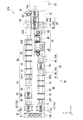
図1は本実施形態に係る基板処理装置SPAを示す平面図である。
基板処理装置SPAは、例えばX方向に一列に配置されたローダ・アンローダLU、塗布現像処理部CD及びインターフェース部IFを備えている。基板処理装置SPAは、塗布現像処理部CDがローダ・アンローダLUとインターフェース部IFによって挟まれて配置された構成になっている。
FIG. 1 is a plan view showing a substrate processing apparatus SPA according to the present embodiment.
The substrate processing apparatus SPA includes, for example, a loader / unloader LU, a coating / development processing unit CD, and an interface unit IF arranged in a line in the X direction. The substrate processing apparatus SPA has a configuration in which a coating / development processing unit CD is disposed between a loader / unloader LU and an interface unit IF.
(ローダ・アンローダ)
ローダ・アンローダLUは、複数の基板Gを収容するカセットCの搬入及び搬出を行う部分である。ローダ・アンローダLUは、カセット待機部10及び搬送機構11を有している。
(Loader / Unloader)
The loader / unloader LU is a part that carries in and out a cassette C that accommodates a plurality of substrates G. The loader / unloader LU includes a
カセット待機部10は、例えば基板処理装置SPAの−X側の端部に配置されており、複数のカセットCを収容する。カセット待機部10に収容されたカセットCは、例えばY方向に配列されるようになっている。カセット待機部10は、−X側に不図示の開口部が形成されており、当該開口部を介して基板処理装置SPAの外部との間でカセットCの受け渡しが行われるようになっている。
The
搬送機構11は、カセット待機部10の+X側に配置されており、カセットCと塗布現像処理部CDとの間で基板Gの搬送を行う。搬送機構11は、例えばY方向に沿って2つ配置されており、当該2つの搬送機構11は例えば同一の構成となっている。−Y側に配置される搬送機構11aは、ローダ・アンローダLUから塗布現像処理部CDへ基板Gを搬送する。+Y側に配置される搬送機構11bは、塗布現像処理部CDからローダ・アンローダLUへ基板Gを搬送する。
The
搬送機構11は搬送アーム12(12a、12b)を有している。搬送アーム12は、ガラス基板を保持する保持部を有し、例えば一方向に伸縮可能に設けられている。搬送アーム12は、θZ方向に回転可能に形成されている。搬送アーム12は、例えばθZ方向に回転することで、カセット待機部10と塗布現像処理部CDとのそれぞれの方向に向かせることが可能になっている。搬送アーム12は、搬送アーム12を伸縮させることで、カセット待機部10及び塗布現像処理部CDのそれぞれにアクセス可能になっている。
The
(塗布現像処理部)
塗布現像処理部CDは、基板Gにレジスト塗布及び現像を含む一連の処理を施す部分である。塗布現像処理部CDは、スクラバユニットSR、脱水ベークユニットDH、塗布ユニットCT、プリベークユニットPR、インターフェース部IF、現像ユニットDV、紫外線照射ユニットUV及びポストベークユニットPBを有している。
(Coating and developing section)
The coating / development processing unit CD is a part that performs a series of processes including resist coating and development on the substrate G. The coating and developing unit CD includes a scrubber unit SR, a dehydrating bake unit DH, a coating unit CT, a prebake unit PR, an interface unit IF, a developing unit DV, an ultraviolet irradiation unit UV, and a post bake unit PB.
塗布現像処理部CDは、Y方向に分割された構成になっており、−Y側の部分では、ローダ・アンローダLUからの基板Gがインターフェース部IFへ向けて+X方向に搬送されるようになっている。+Y側の部分では、インターフェース部IFからの基板Gがローダ・アンローダLUへ向けて−X方向に搬送されるようになっている。 The coating / development processing unit CD is divided in the Y direction, and the substrate G from the loader / unloader LU is transported in the + X direction toward the interface unit IF in the −Y side portion. ing. In the + Y side portion, the substrate G from the interface unit IF is transported in the −X direction toward the loader / unloader LU.
スクラバユニットSRは、ローダ・アンローダLUの下流に接続されており、基板Gの洗浄を行うユニットである。スクラバユニットSRは、ドライ洗浄装置41、ウェット洗浄装置42及びエアナイフ装置43を有している。ドライ洗浄装置41の−X側及びエアナイフ装置43の+X側には、それぞれコンベア機構CV1、CV2が設けられている。コンベア機構CV1、CV2には、基板Gを搬送する不図示のベルト機構が設けられている。
The scrubber unit SR is connected downstream of the loader / unloader LU, and is a unit that cleans the substrate G. The scrubber unit SR has a
ドライ洗浄装置41は、例えば基板Gにエキシマレーザなどの紫外線を照射することにより、基板G上の有機物を除去する。ウェット洗浄装置42は、例えば不図示のスクラビングブラシを有している。ウェット洗浄装置42は、洗浄液及び当該スクラビングブラシを用いて基板Gを洗浄する。エアナイフ装置43は、例えば不図示のエアナイフ噴射機構を有している。エアナイフ装置43は、エアナイフ噴射機構を用いて基板G上にエアナイフを形成し、基板G上の不純物を除去する。
The
脱水ベークユニットDHは、スクラバユニットSRの下流に接続されており、基板G上を脱水するユニットである。脱水ベークユニットDHは、加熱装置44、HMDS装置46及び冷却装置45を有している。加熱装置44及びHMDS装置46は、Z方向に重ねられた状態で配置されている。Z方向視で加熱装置44及びHMDS装置46に重なる位置にコンベア機構CV3が設けられており、Z方向視で冷却装置45に重なる位置にコンベア機構CV4が設けられている。加熱装置44及びHMDS装置46と、冷却装置45との間には、基板Gを搬送する搬送機構TR1が設けられている。搬送機構TR1については、例えばローダ・アンローダLUに設けられた搬送機構11と同一の構成とすることができる。
The dewatering bake unit DH is connected to the downstream side of the scrubber unit SR and is a unit for dewatering the substrate G. The dehydration bake unit DH includes a heating device 44, a HMDS device 46, and a
加熱装置44は、例えば基板Gを収容可能なチャンバ内にヒータを有する構成になっている。加熱装置44は、Z方向に例えば複数段配置されている。加熱装置44は、基板Gを所定の温度で加熱する。HMDS装置46は、HMDSガスを基板Gに作用させて疎水化処理を施し、塗布ユニットCTにおいて基板Gに塗布するレジスト膜と基板Gとの密着性を向上させる装置である。冷却装置45は、例えば基板Gを収容可能なチャンバ内に温調機構を有し、基板Gを所定の温度に冷却する。
The heating device 44 is configured to have a heater in a chamber that can accommodate the substrate G, for example. For example, the heating device 44 is arranged in a plurality of stages in the Z direction. The heating device 44 heats the substrate G at a predetermined temperature. The HMDS apparatus 46 is an apparatus that improves the adhesion between the resist film applied to the substrate G and the substrate G in the coating unit CT by applying HMDS gas to the substrate G to perform a hydrophobic treatment. The
塗布ユニットCTは、脱水ベークユニットDHの下流に接続されており、基板G上の所定の領域にレジスト膜を形成する。塗布ユニットCTは、塗布装置47、減圧乾燥装置48、周縁部除去装置49を有している。塗布装置47は、基板G上にレジスト膜を塗布する装置である。塗布装置47としては、例えば回転式塗布装置、ノンスピン式塗布装置、スリットノズル塗布装置などが用いられる。これら各種の塗布装置を交換可能な構成であっても構わない。減圧乾燥装置48は、レジスト膜を塗布した後の基板Gの表面を乾燥させる。周縁部除去装置49は、基板Gの周縁部に塗布されたレジスト膜を除去し、レジスト膜の形状を整える装置である。
The coating unit CT is connected downstream of the dewatering bake unit DH and forms a resist film in a predetermined region on the substrate G. The coating unit CT includes a
プリベークユニットPRは、塗布ユニットCTの下流に接続されており、基板Gにプリベーク処理を行うユニットである。プリベークユニットPRは、加熱装置50及び冷却装置51を有している。加熱装置50と冷却装置51とは、搬送機構TR2を挟むようにY方向に沿って配置されている。
The pre-bake unit PR is a unit that is connected downstream of the coating unit CT and performs pre-bake processing on the substrate G. The prebake unit PR has a
現像ユニットDVは、プリベークユニットPRの冷却装置51の−X側に接続されており、露光後の基板Gの現像処理を行う。現像ユニットDVは、現像装置55、リンス装置56及びエアナイフ装置57を有している。現像装置55は、基板Gに現像液を供給して現像処理を行う。リンス装置56は、現像後の基板Gにリンス液を供給し、基板Gを洗浄する。エアナイフ装置57は、基板G上にエアナイフを形成し、基板G上を乾燥させる。現像装置55の+X側にはコンベア機構CV9が設けられており、エアナイフ装置57の−X側にはコンベア機構CV10が設けられている。
The development unit DV is connected to the −X side of the
紫外線処理ユニットUVは、現像ユニットDVの下流側に接続されており、現像後の基板Gに例えばi線などの紫外線を照射する。 The ultraviolet processing unit UV is connected to the downstream side of the developing unit DV, and irradiates the developed substrate G with ultraviolet rays such as i-line.
ポストベークユニットPBは、紫外線処理ユニットUVの下流側に接続されており、紫外線処理後の基板Gをベークする。ポストベークユニットPBは、加熱装置59及び冷却装置60を有している。加熱装置59は、現像後の基板Gにポストベークを行う。冷却装置60は、ポストベーク後の基板Gを冷却する。
The post-bake unit PB is connected to the downstream side of the ultraviolet processing unit UV, and bakes the substrate G after the ultraviolet processing. The post bake unit PB includes a
インターフェース部IFは、露光装置EXに接続される部分である。インターフェース部IFは、バッファ装置52、搬送機構TR3、コンベア機構CV7、CV8及び周辺露光装置EEを有している。バッファ装置52は、プリベークユニットPRの搬送機構TR2の+X側に配置されている。バッファ装置52の+X側には、搬送機構TR3が設けられている。
The interface unit IF is a part connected to the exposure apparatus EX. The interface unit IF includes a
バッファ装置52は、基板Gを一時的に待機させておく装置である。バッファ装置52には、基板Gを収容する不図示のチャンバや、当該チャンバ内の温度を調整する温調装置、チャンバ内に収容された基板GのθZ方向の位置を調整する回転制御装置などが設けられている。バッファ装置52のチャンバ内では、基板Gの温度を所定の温度に保持できるようになっている。コンベア機構CV7、CV8は、プリベークユニットPRの冷却装置51をX方向に挟むように配置されている。
The
(紫外線照射装置)
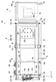
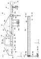
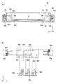
図2は、紫外線処理ユニットUVを+Z側から見たときの構成を示す図である。図3(a)及び図3(b)は、紫外線処理ユニットUVを+Y側から見たときの構成を示す図である。図4(a)は、紫外線処理ユニットUVを−X側から見たときの構成を示す図であり、図4(b)は紫外線処理ユニットUVを+X側から見たときの構成を示す図である。なお、図2〜図4においては、図を判別しやすくするため、それぞれ一部の構成を省略して示している。
(UV irradiation device)
FIG. 2 is a diagram showing a configuration when the ultraviolet processing unit UV is viewed from the + Z side. FIG. 3A and FIG. 3B are diagrams illustrating a configuration when the ultraviolet ray processing unit UV is viewed from the + Y side. 4A is a diagram illustrating a configuration when the ultraviolet processing unit UV is viewed from the −X side, and FIG. 4B is a diagram illustrating a configuration when the ultraviolet processing unit UV is viewed from the + X side. is there. 2 to 4, in order to make it easy to distinguish the drawings, a part of the configuration is omitted.
これらの図に示すように、紫外線処理ユニットUVは、予備装置80及び紫外線処理装置81を有している。
予備装置80は、チャンバ82、減圧機構83及び昇降機構84を有している。予備装置80は、例えば紫外線処理装置81に搬送する基板Gを一時的に収容する予備室として設けられている。勿論、他の用途であっても構わない。予備装置80は、例えば+Y側に基板搬入口80aを有している。予備装置80では、減圧機構83によってチャンバ82内を減圧させた状態で基板G収容することができるようになっている。減圧機構83としては、例えばポンプ機構などが用いられる。
As shown in these drawings, the ultraviolet processing unit UV has a
The
昇降機構84は、Z方向に移動可能に設けられている。昇降機構84の+Z側には、例えば複数の支持ピン84aが設けられている。複数の支持ピン84aの+Z側の端部は、例えばXY平面に平行な同一面内に設けられている。このため、複数の支持ピン84aによって基板GがXY平面に平行に支持されるようになっている。昇降機構84は、チャンバ82内に収容される基板Gを支持しつつ、当該基板Gをチャンバ82内のZ方向に搬送するようになっている。
The elevating
紫外線処理装置81は、予備装置80に接続され、基板Gに対して紫外線の照射を行う装置である。紫外線処理装置81は、チャンバ85、照明機構86、ステージ87、受け渡し機構88、搬送機構89、加熱機構90及び吸引機構91を有している。紫外線処理装置81は、例えば+X側に基板搬入口81aを有している。当該基板搬入口81aは、予備装置80の−X側に接続されている。
The
チャンバ85は、紫外線の照射処理が行われる基板Gを収容する。チャンバ85は、平面視で矩形に形成されており、例えば一方向が長手となるように形成されている。チャンバ85の天井部85aには、紫外線照射用の開口部85bが設けられている。開口部85bは、平面視ではチャンバ85のうち照明機構86に対応する位置に設けられている。また、チャンバ85の天井部85aには、蓋部85cが設けられている。蓋部85cは、複数箇所、例えば平面視でチャンバ85の長手方向に沿って3箇所に設けられている。蓋部85cは、チャンバ85の天井部85aのうち開口部85bから外れた位置に設けられている。
The
チャンバ85内には、開口部85bを挟む位置に遮光部材85dが設けられている。遮光部材85dは、例えばチャンバ85の天井部85aに取り付けられ、照明機構86からの照明光を遮光する板状部材である。遮光部材85dは、例えばチャンバ85内を区切る位置に形成されている。以下、チャンバ85内のうち遮光部材85dによって区切られた部分を、それぞれ第1基板搬送部85F、処理部85P及び第2基板搬送部85Sと表記する。第1基板搬送部85Fは、チャンバ85内のうち予備装置80側の部分である。処理部85Pは、開口部85bが形成された部分である。第2基板搬送部85Sは、予備装置80から最も遠い部分である。
In the
照明機構86は、基板Gに照射する紫外線を照明する。照明機構86は、チャンバ85の開口部85bに取り付けられている。照明機構86は、光源86a及び光量調整部86bを有している。光源86aとしては、紫外線(例えばi線など)を照射する光源が用いられている。光量調整部86bは、基板Gに照射される紫外線の光量を調整する。光源86aからの紫外線は、光量調整部86bによって光量が調整された状態で開口部85bを介して処理部85Pに照射されるようになっている。処理部85Pに照射された紫外線は、遮光部材85dによって遮光されるようになっている。したがって、照明機構86からの紫外線は、第1基板搬送部85F及び第2基板搬送部85Sに照射されること無く、処理部85Pのみに照射されることになる。
The illumination mechanism 86 illuminates the ultraviolet rays with which the substrate G is irradiated. The illumination mechanism 86 is attached to the
ステージ87は、チャンバ85内に収容され、チャンバ85の長手方向に沿って形成された板状部材である。ステージ87は、第1基板搬送部85F、処理部85P及び第2基板搬送部85Sに亘って配置されている。ステージ87は、第1開口部87a、第2開口部87bを有している。第1開口部87aは、第1基板搬送部85Fに配置される部分に形成されている。第2開口部87bは、ステージ87のほぼ全面に亘って形成されている。第2開口部87bは、例えば不図示のエア供給機構及び吸引機構に接続されている。このため、第2開口部87bからはエアが噴出されるようになっており、当該エアによってステージ87上の全面にエアの層が形成されるようになっている。この吸引機構として、例えば吸引機構91を接続させる構成であっても構わない。
The
受け渡し機構88は、基板保持部材88a、伝達部材88b、駆動機構88c及び昇降機構88dを有している。受け渡し機構88は、予備装置80と紫外線処理装置81との両方の装置間を移動可能に設けられている。
The
基板保持部材88aは、櫛状部100及び移動部101を有している。櫛状部100は、例えばY方向において櫛部分が対向するように設けられている。櫛状部100には基板Gが保持されるようになっている。櫛状部100の根元部分は移動部101に接続されている。移動部101は、チャンバ85の+Y側及び−Y側の壁部を貫通するように設けられている。移動部101は、チャンバ85の+Y側及び−Y側に固定機構102を有している。移動部101は、固定機構102を介して上記伝達部材88bに固定されている。
The
伝達部材88bとしては、例えばワイヤーなどの線状部材が用いられている。伝達部材88bは、少なくともチャンバ85の+Y側及び−Y側の側部に接するように環状に形成されている。伝達部材88bは、当該チャンバ85の+Y側及び−Y側においてはX方向に沿って設けられている。
As the
図2及び図4(b)に示すように、伝達部材88bは、チャンバ85の−X側の角部においてそれぞれプーリ部88f、88gによってY方向に引き回されている。図4(b)に示すように、チャンバ85の−X側端面にはプーリ部88hが複数設けられている。伝達部材88bは、チャンバ85の−X側端面において当該プーリ部88hを介して駆動機構88cに接続されている。また、伝達部材88bの+X側においては、図2及び図3(b)に示すように、チャンバ85の+X側の角部に設けられるプーリ部88i、88jに掛けられている。
As shown in FIGS. 2 and 4B, the
駆動機構88cは、チャンバ85の外部であって当該チャンバ85の−Z側に設けられている。駆動機構88cは、不図示のモータを有しており、当該モータを回転させることによって伝達部材88bを駆動させる構成になっている。昇降機構88dは、第1基板搬送部85Fの−Z側に設けられており、不図示のアクチュエータによってZ方向に移動可能に設けられている。昇降機構88dは、複数の支持ピン88eを有している。支持ピン88eは、ステージ87に設けられた第1開口部87aにZ方向視で重なる位置に配置されている。昇降機構88dがZ方向に移動することにより、支持ピン88eが第1開口部87aに対してステージ87上に出没するようになっている。
The
受け渡し機構88は、チャンバ85の外部に設けられる駆動機構88cによって伝達部材88bを駆動させることで、当該伝達部材88bを介して基板保持部材88aをX方向に移動するようになっている。このように、チャンバ85の外部に設けられる駆動機構88cの駆動により、チャンバ85の内部の基板保持部材88aを移動させることができるようになっている。また、受け渡し機構88では、昇降機構88dをZ方向に移動させることにより、櫛状部100に保持された基板Gを受け取ることができるようになっている。
The
搬送機構89は、基板保持部材89a、伝達部材89b及び駆動機構89cを有している。例えば図4(a)などに示すように、搬送機構89は、受け渡し機構88の−Z側に設けられている。
基板保持部材89aは、Z方向視L字型に形成されており、基板Gの角部に対応する位置に1つずつ、計4つ配置されている。基板保持部材89aは、基板Gの角部を保持可能になっている。より具体的には、基板保持部材89aは、基板Gの角部のうちX側及びY側の面(側面)と−Z側の面(底面)とを保持するようになっている。4つの基板保持部材89aは、支持用ワイヤー105に固定されている。支持用ワイヤー105は、X方向に沿って設けられているワイヤーが2本、Y方向に沿って設けられているワイヤーが4本の、計6本のワイヤーによって構成されている。支持用ワイヤー105は、全て張力が加えられた状態になっている。
The
The
X方向に沿って設けられている2本のワイヤー105Xは、4つの基板保持部材89aのうちX方向に沿って配置される基板保持部材89a同士を接続する。Y方向に沿って設けられている4本のワイヤー105Yは、チャンバ85をY方向に貫通して設けられている。4本のワイヤー105Yのうち最も+X側のワイヤー105Yは、支持部材106を介して+X側の2つの基板保持部材89aに接続されている。最も−X側のワイヤー105Yは、支持部材107を介して−X側の2つの基板保持部材89aに接続されている。
The two
チャンバ85の+Y側には伝達部材89bに固定される2つの固定機構108が設けられている。ワイヤー105Yの+Y側端部は当該2つの固定機構108にそれぞれ接続されている。チャンバ85の−Y側には伝達部材89bに固定される2つの固定機構109が設けられており、ワイヤー105Yの−Y側端部は当該固定機構109にそれぞれ接続されている。
On the + Y side of the
伝達部材89bとしては、例えばワイヤーなどの線状部材が用いられている。伝達部材89bは、例えば2本設けられている。上記の2つの固定機構108及び固定機構109は、各伝達部材89bに1つずつ固定されている。したがって、2つの伝達部材89bのうち1本が−X側の2つの基板保持部材89aに接続されており、伝達部材89bのもう1本が+X側の2つの基板保持部材89aに接続されている。
As the
各伝達部材89bは、例えばチャンバ85の側部においてはX方向に沿って設けられている。また、各伝達部材89bは、少なくともチャンバ85の+Y側及び−Y側の側部に接するように環状に形成されている。各伝達部材89bは、当該チャンバ85の+Y側及び−Y側においてはX方向に沿って設けられている。
Each
図2及び図4(b)に示すように、各伝達部材89bは、チャンバ85の−X側の角部においてそれぞれプーリ部89f、89gによってY方向に引き回されている。図4(b)に示すように、チャンバ85の−X側端面にはプーリ部89hが複数設けられている。各伝達部材89bは、チャンバ85の−X側端面において当該プーリ部89hを介して駆動機構89cに接続されている。プーリ部89f、89g及び89hにより、2本の伝達部材89bが絡まないように独立して移動可能になっている。
As shown in FIGS. 2 and 4B, each
なお、プーリ部88f、89f、88g、89g、88h、89hの配置は、上記伝達部材88b及び2本の伝達部材89bがそれぞれ絡まないように独立して移動できる形態であれば、本実施形態で示した配置に限られることは無く、他の配置であっても勿論構わない。
In this embodiment, the
伝達部材89bとしては、例えば伝達部材88bと同様、例えばワイヤーなどの線状部材が用いられている。図3(b)に示すように、搬送機構89に設けられる伝達部材89bは、受け渡し機構88に設けられる伝達部材88bに対して−Z側に配置されている。また、図2等に示すように、伝達部材88bと伝達部材89bのうち、例えばチャンバ85に沿って設けられるそれぞれの部分は、Z方向視で重なるように配置されている。したがって、伝達部材88bと同様、伝達部材89bは、例えばチャンバ85の側部においてはX方向に沿って設けられている。
As the
図2及び図4(b)に示すように、各伝達部材89bは、チャンバ85の−X側の角部においてそれぞれプーリ部89f、89gによってY方向に引き回されている。図4(b)に示すように、チャンバ85の−X側端面にはプーリ部89hが複数設けられている。各伝達部材89bは、チャンバ85の−X側端面において当該プーリ部89hを介して駆動機構89cに接続されている。また、各伝達部材89bの+X側においては、図2及び図3(b)に示すように、チャンバ85の+X側の角部に設けられるプーリ部89i、89jに掛けられている。
As shown in FIGS. 2 and 4B, each
駆動機構89cは、チャンバ85の外部であって当該チャンバ85の−Z側に設けられている。駆動機構89cは、不図示のモータを有しており、当該モータを回転させることによって各伝達部材89bを駆動させる構成になっている。駆動機構89cは、2つの伝達部材89bについて、それぞれ1つずつ設けられている。駆動機構89cを例えば同期制御することにより、4つの基板保持部材89aを等しい速度で移動させることができるようになっている。
The
搬送機構89は、駆動機構89cによって伝達部材89bを駆動させることで、当該伝達部材89bを介して基板保持部材89aをX方向に移動するようになっている。このように、チャンバ85の外部に設けられる駆動機構89cの駆動により、チャンバ85の内部の基板保持部材89aを移動させることができるようになっている。
The
加熱機構90は、例えばチャンバ85の処理部85Pの底部に設けられている。加熱機構90は、内部に例えば電熱線などの加熱部や、当該加熱部の加熱温度を調整する温度制御部などを有している。吸引機構91は、チャンバ85内を吸引する。吸引機構91としては、例えばポンプ機構などが用いられる。
The
(基板処理方法、紫外線照射方法)
以上のように構成された基板処理装置SPAを用いる基板処理方法を説明する。
まず、基板Gが収容されたカセットCをローダ・アンローダLUのカセット待機部10にロードする。カセットC内の基板Gは、搬送機構11を介してスクラバユニットSRへ搬送される。
(Substrate processing method, UV irradiation method)
A substrate processing method using the substrate processing apparatus SPA configured as described above will be described.
First, the cassette C containing the substrate G is loaded into the
スクラバユニットSRに搬送された基板Gは、コンベア機構CV1を介してドライ洗浄装置41へ搬送される。この基板Gは、ドライ洗浄装置41、ウェット洗浄装置42及びエアナイフ装置43と順に処理される。エアナイフ装置43から搬出された基板Gは、コンベア機構CV2を介して脱水ベークユニットDHへと搬送される。
The substrate G transported to the scrubber unit SR is transported to the
脱水ベークユニットDHでは、まず加熱装置44によって基板Gの加熱処理が行われる。加熱後の基板Gは、例えばZ方向に搬送され、HMDS装置46においてHMDSガスによる処理が行われる。HMDS処理後の基板Gは、搬送機構TR1によって冷却装置45に搬送され、冷却処理が行われる。冷却処理後の基板Gは、コンベア機構CV4によって塗布ユニットCTに搬送される。
In the dehydration bake unit DH, first, the substrate G is heated by the heating device 44. The heated substrate G is transported, for example, in the Z direction, and processing with HMDS gas is performed in the HMDS apparatus 46. The substrate G after the HMDS process is transported to the
その後、基板Gは塗布ユニットCTにおいてレジスト膜の塗布処理が行われる。塗布処理後の基板GはプリベークユニットPRに搬送され、加熱装置50においてプリベーク処理が行われ、冷却装置51において冷却処理が行われる。プリベークユニットPRでの処理を完了させた基板Gは、搬送機構TR2によってインターフェース部IFに搬送される。
Thereafter, the substrate G is subjected to a resist film coating process in the coating unit CT. The substrate G after the coating process is transported to the pre-bake unit PR, the pre-bake process is performed in the
インターフェース部IFでは、例えばバッファ装置52において温度調整が行われた後、周辺露光装置EEにおいて周辺露光が行われる。周辺露光の後、基板Gは、搬送機構TR3によって露光装置EXに搬送され、露光処理が行われる。露光処理後の基板Gは、加熱処理及び冷却処理が行われた後、現像ユニットDVに搬送される。
In the interface unit IF, for example, temperature adjustment is performed in the
現像ユニットDVにおいて、基板Gには現像処理、リンス処理及び乾燥処理が順に行われる。乾燥処理の後、コンベア機構CV10によって基板Gは紫外線処理ユニットUVへと搬送される。 In the developing unit DV, the substrate G is subjected to a developing process, a rinsing process, and a drying process in order. After the drying process, the substrate G is transported to the ultraviolet processing unit UV by the conveyor mechanism CV10.
紫外線処理ユニットUVでは、基板Gはまず予備装置80のチャンバ82内に搬送される。チャンバ82内に基板Gが搬送された後、チャンバ82を密閉し減圧機構83を作動させて減圧処理を行う。減圧処理の後、昇降機構84を+Z側に移動させ、支持ピン84aによって基板Gを持ち上げた状態にする。このとき、受け渡し機構88の基板保持部材88aの高さよりも高い位置(+Z側の位置)まで基板Gを持ち上げる。
In the ultraviolet processing unit UV, the substrate G is first transported into the
基板Gを持ち上げた後、基板保持部材88aの櫛状部100をチャンバ82内に挿入させ、櫛状部100を基板Gの−Z側に配置させる。櫛状部100が配置された後、昇降機構84を−Z側に移動させ、持ち上げた基板Gを−Z側に移動させる。基板Gの−Z側には櫛状部100が配置されているため、支持ピン84aから櫛状部100へと基板Gが渡される。
After lifting the substrate G, the comb-shaped
基板Gを受け取った後、駆動機構88cの駆動により伝達部材88bを介して基板保持部材88aを−X側に移動させ、基板Gをチャンバ85内に搬入する。基板Gの搬入後、チャンバ85内を密閉し、吸引機構91を作動させてチャンバ85内を減圧する。また、チャンバ85内を減圧しつつ駆動機構88cを更に駆動させ、第1基板搬送部85Fの第1開口部87aにZ方向視で重なるように基板Gを配置する。
After receiving the substrate G, the
基板Gの配置後、昇降機構88dを+Z側に移動させ、支持ピン88eを第1開口部87aから突出させる。支持ピン88eの+Z側には基板Gが配置されているため、基板保持部材88aから支持ピン88eへ基板Gが渡されることになる。基板Gが渡された後、駆動機構89cを駆動させ、基板Gの−Z側に基板保持部材89aを移動させる。このとき、4つの基板保持部材89aが基板Gの4つの角部にそれぞれZ方向視で重なるように駆動機構89cを駆動させる。
After the placement of the substrate G, the
基板保持部材89aを配置させた後、昇降機構88dを−Z側に移動させ、基板Gを−Z側に移動させる。基板Gの−Z側には基板保持部材89aが配置されているため、支持ピン88eから基板保持部材89aへと基板Gが渡される。この基板Gが渡される際に、例えば不図示のエア供給部を作動させ、第2開口部87bにおいて所定の噴出量及び吸引量でエアを噴出及び吸引させ、ステージ87上にエアの層を形成しておく。基板Gが渡される際、基板Gとステージ87との間にはエア層が形成されているため、基板Gはエア層と基板保持部材89aとで保持されることになる。このため、基板保持部材89aが基板Gの角部のみを保持する構成であっても、基板Gが撓んだり割れたりすること無く安定して保持されることになる。
After the
基板Gが基板保持部材89aに保持された後、駆動機構89cを駆動させて基板Gを処理部85Pへ搬送する。基板Gはエアの層上に浮上して搬送されることになるため、少ない駆動力で基板Gを搬送させることができる。このため、伝達部材89bの負担が小さくて済むことになる。基板Gが処理部85Pに搬送された後、当該基板Pを処理部85P内で−X側に搬送しつつ、照明機構86及び加熱機構90を作動させる。この動作により、処理部85Pでは、基板Pが搬送されかつ加熱された状態で照明機構86から基板Gの表面に紫外線が照射されることになる。処理部85Pの+X側及び−X側には遮光部材85dが設けられているため、紫外線が処理部85Pから漏れることなく処理が行われることになる。
After the substrate G is held by the
処理部85Pでは基板Gを搬送させながら紫外線が照射されるため、基板Gは紫外線照射が完了した部分から徐々に第2基板搬送部85Sへ搬出されていく。基板Gの全部に対して紫外線照射が完了した場合、基板Gの全部が第2基板搬送部85Sに収容されることになる。紫外線照射が完了した後、照明機構86及び加熱機構90の作動を停止させ、基板Gを第1基板搬送部85Fへと搬送する。
Since the
第1基板搬送部85Fに搬送された基板Gは、搬送機構89から基板受け渡し機構88へと渡され、基板受け渡し機構88によってチャンバ85からチャンバ82へと搬送される。チャンバ82では、基板受け渡し機構88から昇降機構84へと基板Gが渡され、その後不図示の搬送機構を介して基板Gがチャンバ82から紫外線処理ユニットUVの外部へ搬出される。
The substrate G transferred to the first
次に、基板Gは加熱装置59においてポストベーク処理が行われ、冷却装置60において冷却される。冷却処理後、基板Gは搬送機構11を介してカセットCに収容される。このようにして、基板Gに対して塗布処理、露光処理及び現像処理の一連の処理が行われることとなる。
Next, the substrate G is subjected to a post-baking process in the
以上のように、本実施形態によれば、紫外線処理ユニットUVにおいて駆動機構88c、89cがチャンバ85の外部に設けられることとしたので、駆動機構88c、89cによるチャンバ内のゴミの巻上げを防ぐことができる。加えて、本実施形態によれば、伝達部材88b、89bによって駆動機構88c、89cの駆動力を基板保持部材88a、89aに伝達することで基板保持部材88a、89aを移動させる構成としたので、基板Gの搬送に用いるスペースを抑えることができ、チャンバ85内の気流が乱されるのを抑えることができる。これにより、チャンバ85内の環境を清浄に保持することができ、基板Gに異物が付着するのを抑制できるため、スループットの低下を防ぐことができる。
As described above, according to the present embodiment, since the
本発明の技術範囲は上記実施形態に限定されるものではなく、本発明の趣旨を逸脱しない範囲で適宜変更を加えることができる。
例えば、上記実施形態では、伝達部材88b、89bとして、ワイヤーなどの線状部材を用いた構成を例に挙げて説明したが、これに限られることは無く、例えばベルトなどの帯状部材を用いた構成としても構わない。伝達部材88b、89bの引き回し方向を3次元空間内で転換させる場合、例えばプーリ機構を45°傾けるようにすることで、帯状部材が折れ曲がることなく回転することができる。
The technical scope of the present invention is not limited to the above-described embodiment, and appropriate modifications can be made without departing from the spirit of the present invention.
For example, in the above-described embodiment, the
また、上記実施形態では、ステージ87に第2開口部87bを配置し、当該第2開口部87bを用いてエアを噴出及び吸引させることでステージ87上にエアの層を形成し、当該エアの層を用いて基板Gを保持して浮上搬送させる構成としたが、これに限られることは無く、基板Gを浮上させずに保持する構成としても構わない。
In the above embodiment, the
また、上記実施形態では、紫外線処理装置81の予備装置80を例えば基板Gの減圧室として用いる構成を例に挙げて説明したが、これに限られることは無く、他の装置を用いる構成であっても構わない。当該他の装置としては、例えば基板Gの加熱装置や冷却装置、搬送装置などを挙げることができ、更には上記基板処理装置SPAを構成する各装置などを挙げることができる。
In the above-described embodiment, the configuration in which the
また、上記実施形態では、予備装置80の基板搬入口80aが+Y側に配置され、紫外線処理装置81の基板搬入口81aが+X側に配置された構成を例に挙げて説明したが、これに限られることは無く、これら基板搬入口80a及び基板搬入口81aをどの方向に配置しても構わない。
In the above embodiment, the substrate carry-in
また、上記実施形態では、遮光部材85dが開口部85bを挟む位置に設けられる構成としたが、これに限られることは無く、例えば照明装置86を冷却する冷媒の流路等が照明装置86に近接して設けられている場合、照明装置86の外径に沿った位置(開口部85bの内側の位置)に遮光部材85dを配置する構成であっても構わない。
In the above embodiment, the
また、上記実施形態の態様に加えて、紫外線処理装置81内で基板Gを搬送する場合、照明機構86の−Z側を通過する際に搬送速度を変化させることで基板Gのパターン形状を調整する構成であっても構わない。
In addition to the above embodiment, when the substrate G is transported in the ultraviolet
SPA…基板処理装置 G…基板 UV…紫外線処理ユニット 80…予備装置 81…紫外線処理装置 82、85…チャンバ 83…減圧機構 84…昇降機構 86…照明機構 87…ステージ 88…受け渡し機構 89…搬送機構 88a、89a…基板保持部材 88b、89b…伝達部材 88c、89c…駆動機構 88d…昇降機構 88f、88g、88h、88i、88j…プーリ部 90…加熱機構 91…吸引機構
SPA ... Substrate processing device G ... Substrate UV ...
Claims (4)
前記保持機構に保持され前記チャンバ内を移動している前記基板に紫外線を照射する紫外線照射機構と、
前記チャンバ内の前記基板を加熱する加熱機構と、
前記チャンバ外部に設けられた駆動源、及び、前記保持機構に接続され前記駆動源の駆動力を前記保持機構に伝達する伝達部材、を有する移動機構と、
前記チャンバ内に設けられ、前記保持機構に保持された前記基板に対してエアを噴出し前記基板を浮上させる機構を有するステージと、
を備えることを特徴とする紫外線照射装置。 A holding mechanism provided in the chamber and provided to be movable while holding the substrate;
An ultraviolet irradiation mechanism that irradiates the substrate that is held in the holding mechanism and moves in the chamber with ultraviolet rays;
A heating mechanism for heating the substrate in the chamber;
A moving mechanism having a driving source provided outside the chamber, and a transmission member connected to the holding mechanism and transmitting a driving force of the driving source to the holding mechanism;
A stage provided in the chamber and having a mechanism for ejecting air to the substrate held by the holding mechanism and floating the substrate;
An ultraviolet irradiation device comprising:
前記チャンバ内で前記基板にエアを噴出して前記基板を浮上させ、前記チャンバ外部に設けられた駆動源から伝達部材を介して前記保持機構に駆動力を伝達し、前記保持機構を移動させる移動ステップと
を備えることを特徴とする紫外線照射方法。 An ultraviolet irradiation step of holding the substrate by a holding mechanism and irradiating the substrate that is held in the holding mechanism and moving in the chamber with ultraviolet rays;
Air that blows air onto the substrate in the chamber to float the substrate, transmits a driving force from a driving source provided outside the chamber to the holding mechanism via a transmission member, and moves the holding mechanism An ultraviolet irradiation method comprising the steps of:
Priority Applications (1)
| Application Number | Priority Date | Filing Date | Title |
|---|---|---|---|
| JP2014043806A JP2014123769A (en) | 2014-03-06 | 2014-03-06 | Ultraviolet irradiation device and ultraviolet irradiation method |
Applications Claiming Priority (1)
| Application Number | Priority Date | Filing Date | Title |
|---|---|---|---|
| JP2014043806A JP2014123769A (en) | 2014-03-06 | 2014-03-06 | Ultraviolet irradiation device and ultraviolet irradiation method |
Related Parent Applications (1)
| Application Number | Title | Priority Date | Filing Date |
|---|---|---|---|
| JP2009249114A Division JP5492527B2 (en) | 2009-10-29 | 2009-10-29 | Ultraviolet irradiation apparatus, ultraviolet irradiation method and substrate processing apparatus |
Publications (1)
| Publication Number | Publication Date |
|---|---|
| JP2014123769A true JP2014123769A (en) | 2014-07-03 |
Family
ID=51403963
Family Applications (1)
| Application Number | Title | Priority Date | Filing Date |
|---|---|---|---|
| JP2014043806A Pending JP2014123769A (en) | 2014-03-06 | 2014-03-06 | Ultraviolet irradiation device and ultraviolet irradiation method |
Country Status (1)
| Country | Link |
|---|---|
| JP (1) | JP2014123769A (en) |
Cited By (2)
| Publication number | Priority date | Publication date | Assignee | Title |
|---|---|---|---|---|
| JP2016114784A (en) * | 2014-12-15 | 2016-06-23 | 東京応化工業株式会社 | Ultraviolet ray radiation device, ultraviolet ray radiation method, substrate processing device, and production method of substrate processing device |
| KR20160118943A (en) | 2015-04-02 | 2016-10-12 | 우시오덴키 가부시키가이샤 | Light irradiating apparatus |
Citations (9)
| Publication number | Priority date | Publication date | Assignee | Title |
|---|---|---|---|---|
| JPS6039238U (en) * | 1983-08-24 | 1985-03-19 | ウシオ電機株式会社 | UV cleaning equipment |
| JPH02130849A (en) * | 1988-11-11 | 1990-05-18 | Hitachi Ltd | Conveyor |
| JPH0758189A (en) * | 1993-08-20 | 1995-03-03 | Hitachi Ltd | Modifying device |
| JP2003300618A (en) * | 2002-04-10 | 2003-10-21 | Orc Mfg Co Ltd | Base transporting mechanism |
| JP2006019396A (en) * | 2004-06-30 | 2006-01-19 | Tokyo Electron Ltd | Substrate processing device |
| JP2006266722A (en) * | 2005-03-22 | 2006-10-05 | Olympus Corp | System and method for inspecting substrate |
| JPWO2005074020A1 (en) * | 2004-01-30 | 2007-09-13 | シャープ株式会社 | Semiconductor manufacturing apparatus and semiconductor manufacturing method using the same |
| JP2009023804A (en) * | 2007-07-20 | 2009-02-05 | Olympus Corp | Substrate transporting apparatus and substrate transporting method |
| JP2009098052A (en) * | 2007-10-18 | 2009-05-07 | Toppan Printing Co Ltd | Substrate gripping mechanism for substrate transferring device |
-
2014
- 2014-03-06 JP JP2014043806A patent/JP2014123769A/en active Pending
Patent Citations (9)
| Publication number | Priority date | Publication date | Assignee | Title |
|---|---|---|---|---|
| JPS6039238U (en) * | 1983-08-24 | 1985-03-19 | ウシオ電機株式会社 | UV cleaning equipment |
| JPH02130849A (en) * | 1988-11-11 | 1990-05-18 | Hitachi Ltd | Conveyor |
| JPH0758189A (en) * | 1993-08-20 | 1995-03-03 | Hitachi Ltd | Modifying device |
| JP2003300618A (en) * | 2002-04-10 | 2003-10-21 | Orc Mfg Co Ltd | Base transporting mechanism |
| JPWO2005074020A1 (en) * | 2004-01-30 | 2007-09-13 | シャープ株式会社 | Semiconductor manufacturing apparatus and semiconductor manufacturing method using the same |
| JP2006019396A (en) * | 2004-06-30 | 2006-01-19 | Tokyo Electron Ltd | Substrate processing device |
| JP2006266722A (en) * | 2005-03-22 | 2006-10-05 | Olympus Corp | System and method for inspecting substrate |
| JP2009023804A (en) * | 2007-07-20 | 2009-02-05 | Olympus Corp | Substrate transporting apparatus and substrate transporting method |
| JP2009098052A (en) * | 2007-10-18 | 2009-05-07 | Toppan Printing Co Ltd | Substrate gripping mechanism for substrate transferring device |
Cited By (2)
| Publication number | Priority date | Publication date | Assignee | Title |
|---|---|---|---|---|
| JP2016114784A (en) * | 2014-12-15 | 2016-06-23 | 東京応化工業株式会社 | Ultraviolet ray radiation device, ultraviolet ray radiation method, substrate processing device, and production method of substrate processing device |
| KR20160118943A (en) | 2015-04-02 | 2016-10-12 | 우시오덴키 가부시키가이샤 | Light irradiating apparatus |
Similar Documents
| Publication | Publication Date | Title |
|---|---|---|
| JP5904169B2 (en) | Substrate cleaning apparatus, substrate cleaning method, and storage medium | |
| JP4704221B2 (en) | Substrate processing apparatus and substrate processing method | |
| JP4413789B2 (en) | Stage device and coating treatment device | |
| JP5102717B2 (en) | Substrate transport apparatus and substrate processing apparatus provided with the same | |
| JP2009194034A (en) | Cleaning device and its method, coating, developer and its method, and storage medium | |
| JP5891013B2 (en) | Ultraviolet irradiation apparatus and substrate processing apparatus | |
| JP2016027588A (en) | Light irradiation apparatus, apparatus for processing substrate and method for manufacturing apparatus for processing substrate | |
| JP5503057B2 (en) | Vacuum drying apparatus and vacuum drying method | |
| KR102315667B1 (en) | Method and Apparatus for treating substrate | |
| JP6058999B2 (en) | Substrate processing apparatus and substrate processing method | |
| JP4845668B2 (en) | Application / development processing equipment with composite piping and composite piping | |
| JP6418932B2 (en) | Ultraviolet irradiation apparatus, ultraviolet irradiation method, substrate processing apparatus, and manufacturing method of substrate processing apparatus | |
| JP2014123769A (en) | Ultraviolet irradiation device and ultraviolet irradiation method | |
| JP2009117462A (en) | Coating film forming device, substrate transfer method and storage medium | |
| JP5492527B2 (en) | Ultraviolet irradiation apparatus, ultraviolet irradiation method and substrate processing apparatus | |
| JP2007067375A (en) | Heating/cooling device, substrate processing device and substrate processing method | |
| JP2002299405A (en) | Substrate transporting apparatus | |
| JP6349208B2 (en) | Ultraviolet irradiation apparatus, ultraviolet irradiation method, substrate processing apparatus, and manufacturing method of substrate processing apparatus | |
| JP5283770B2 (en) | Substrate transport apparatus and substrate processing apparatus provided with the same | |
| KR20200026563A (en) | Transfer robot and Apparatus for treating substrate with the robot | |
| JP2010192559A (en) | Substrate processing system | |
| JP2019201104A (en) | Substrate processing apparatus and substrate processing method | |
| TWI721804B (en) | Substrate processing apparatus | |
| JP2015050304A (en) | Light irradiation device, substrate processing apparatus, and process of manufacturing the same | |
| KR102343640B1 (en) | Apparatus for treating substrate |
Legal Events
| Date | Code | Title | Description |
|---|---|---|---|
| A977 | Report on retrieval |
Free format text: JAPANESE INTERMEDIATE CODE: A971007 Effective date: 20150121 |
|
| A131 | Notification of reasons for refusal |
Free format text: JAPANESE INTERMEDIATE CODE: A131 Effective date: 20150203 |
|
| A521 | Written amendment |
Free format text: JAPANESE INTERMEDIATE CODE: A523 Effective date: 20150318 |
|
| A521 | Written amendment |
Free format text: JAPANESE INTERMEDIATE CODE: A821 Effective date: 20150319 |
|
| A02 | Decision of refusal |
Free format text: JAPANESE INTERMEDIATE CODE: A02 Effective date: 20151117 |
|
| A521 | Written amendment |
Free format text: JAPANESE INTERMEDIATE CODE: A523 Effective date: 20160212 |
|
| A521 | Written amendment |
Free format text: JAPANESE INTERMEDIATE CODE: A821 Effective date: 20160215 |
|
| A911 | Transfer of reconsideration by examiner before appeal (zenchi) |
Free format text: JAPANESE INTERMEDIATE CODE: A911 Effective date: 20160223 |
|
| A912 | Removal of reconsideration by examiner before appeal (zenchi) |
Free format text: JAPANESE INTERMEDIATE CODE: A912 Effective date: 20160422 |