KR20200026563A - Transfer robot and Apparatus for treating substrate with the robot - Google Patents
Transfer robot and Apparatus for treating substrate with the robot Download PDFInfo
- Publication number
- KR20200026563A KR20200026563A KR1020180104667A KR20180104667A KR20200026563A KR 20200026563 A KR20200026563 A KR 20200026563A KR 1020180104667 A KR1020180104667 A KR 1020180104667A KR 20180104667 A KR20180104667 A KR 20180104667A KR 20200026563 A KR20200026563 A KR 20200026563A
- Authority
- KR
- South Korea
- Prior art keywords
- substrate
- hand
- unit
- buffer
- module
- Prior art date
Links
Images


Classifications
-
- H—ELECTRICITY
- H01—ELECTRIC ELEMENTS
- H01L—SEMICONDUCTOR DEVICES NOT COVERED BY CLASS H10
- H01L21/00—Processes or apparatus adapted for the manufacture or treatment of semiconductor or solid state devices or of parts thereof
- H01L21/67—Apparatus specially adapted for handling semiconductor or electric solid state devices during manufacture or treatment thereof; Apparatus specially adapted for handling wafers during manufacture or treatment of semiconductor or electric solid state devices or components ; Apparatus not specifically provided for elsewhere
- H01L21/677—Apparatus specially adapted for handling semiconductor or electric solid state devices during manufacture or treatment thereof; Apparatus specially adapted for handling wafers during manufacture or treatment of semiconductor or electric solid state devices or components ; Apparatus not specifically provided for elsewhere for conveying, e.g. between different workstations
- H01L21/67739—Apparatus specially adapted for handling semiconductor or electric solid state devices during manufacture or treatment thereof; Apparatus specially adapted for handling wafers during manufacture or treatment of semiconductor or electric solid state devices or components ; Apparatus not specifically provided for elsewhere for conveying, e.g. between different workstations into and out of processing chamber
- H01L21/67742—Mechanical parts of transfer devices
-
- H—ELECTRICITY
- H01—ELECTRIC ELEMENTS
- H01L—SEMICONDUCTOR DEVICES NOT COVERED BY CLASS H10
- H01L21/00—Processes or apparatus adapted for the manufacture or treatment of semiconductor or solid state devices or of parts thereof
- H01L21/67—Apparatus specially adapted for handling semiconductor or electric solid state devices during manufacture or treatment thereof; Apparatus specially adapted for handling wafers during manufacture or treatment of semiconductor or electric solid state devices or components ; Apparatus not specifically provided for elsewhere
- H01L21/67005—Apparatus not specifically provided for elsewhere
- H01L21/67011—Apparatus for manufacture or treatment
- H01L21/67098—Apparatus for thermal treatment
-
- H—ELECTRICITY
- H01—ELECTRIC ELEMENTS
- H01L—SEMICONDUCTOR DEVICES NOT COVERED BY CLASS H10
- H01L21/00—Processes or apparatus adapted for the manufacture or treatment of semiconductor or solid state devices or of parts thereof
- H01L21/67—Apparatus specially adapted for handling semiconductor or electric solid state devices during manufacture or treatment thereof; Apparatus specially adapted for handling wafers during manufacture or treatment of semiconductor or electric solid state devices or components ; Apparatus not specifically provided for elsewhere
- H01L21/683—Apparatus specially adapted for handling semiconductor or electric solid state devices during manufacture or treatment thereof; Apparatus specially adapted for handling wafers during manufacture or treatment of semiconductor or electric solid state devices or components ; Apparatus not specifically provided for elsewhere for supporting or gripping
- H01L21/687—Apparatus specially adapted for handling semiconductor or electric solid state devices during manufacture or treatment thereof; Apparatus specially adapted for handling wafers during manufacture or treatment of semiconductor or electric solid state devices or components ; Apparatus not specifically provided for elsewhere for supporting or gripping using mechanical means, e.g. chucks, clamps or pinches
- H01L21/68707—Apparatus specially adapted for handling semiconductor or electric solid state devices during manufacture or treatment thereof; Apparatus specially adapted for handling wafers during manufacture or treatment of semiconductor or electric solid state devices or components ; Apparatus not specifically provided for elsewhere for supporting or gripping using mechanical means, e.g. chucks, clamps or pinches the wafers being placed on a robot blade, or gripped by a gripper for conveyance
Abstract
Description
본 발명은 기판 처리 장치에 관한 것이다. The present invention relates to a substrate processing apparatus.
일반적으로 웨이퍼는 이온주입공정, 막 증착 공정, 확산 공정, 사진식각공정 등과 같은 다수의 공정들을 통해 제조되는데, 이러한 공정들 중에서 웨이퍼에 원하는 패턴을 형성하기 위한 사진식각공정은 식각이나 이온이 주입될 부위와 보호될 부위를 선택적으로 정의하기 위하여 소정의 패턴을 웨이퍼 위에 형성하는 것으로, 웨이퍼 상에 포토레지스트를 떨어뜨린 후 고속으로 회전시켜 웨이퍼 위에 소정 두께로 포토레지스트 층이 형성되도록 하는 도포공정과, 포토레지스트 층이 형성된 웨이퍼와 마스크를 정렬시킨 후 자외선과 같은 빛이 마스트를 통해 웨이퍼 상의 포토레지스트 층에 조사되도록 하여 마스크 또는 레티클의 패턴이 웨이퍼에 옮겨지도록 하는 노광공정과, 노광공정이 완료된 포토레지스트 층을 현상하여 원하는 포토레지스트 패턴을 형성하는 현상공정으로 이루어진다.In general, a wafer is manufactured through a number of processes such as an ion implantation process, a film deposition process, a diffusion process, and a photolithography process. Among these processes, a photolithography process for forming a desired pattern on a wafer may be performed by etching or ion implantation. Forming a predetermined pattern on the wafer to selectively define the portion and the portion to be protected, the application process of dropping the photoresist on the wafer and rotating it at high speed to form a photoresist layer on the wafer at a predetermined thickness; After aligning the mask and the wafer on which the photoresist layer is formed, an exposure process for irradiating a photoresist layer on the wafer with a mask such as ultraviolet light to transfer the pattern of the mask or reticle onto the wafer; Develop the layer to pattern the desired photoresist It comprises a developing step of forming.
또한, 사진식각공정에는 웨이퍼를 소정 온도하에서 굽는 베이킹 공정이 포함된다. 베이킹 공정으로는 도포공정이 이루어지기 전에 웨이퍼에 흡착된 수분을 제거하기 위한 프리 베이킹 공정과, 포토레지스트를 도포한 후 포토레지스트 층을 건조시켜 포토레지스트 층이 웨이퍼의 표면에 고착되게 하는 소프트 베이킹 공정과, 노광공정 후에 포토레지스트 층을 가열하는 노광 후 베이팅 단계와, 현상공정에 의해 형성된 패턴이 웨이퍼 상에 견고하게 부착되도록 하는 하드 베이킹 공정을 포함한다.In addition, the photolithography process includes a baking process of baking the wafer at a predetermined temperature. The baking process includes a pre-baking step for removing moisture adsorbed on the wafer before the coating step is performed, and a soft baking step for drying the photoresist layer after applying the photoresist to adhere the photoresist layer to the surface of the wafer. And a post-exposure baiting step of heating the photoresist layer after the exposure process, and a hard baking process to firmly adhere the pattern formed by the developing process onto the wafer.
이러한 사진 공정을 진행하는 설비에서는 다수의 반송 로봇이 사용되며, 각각의 반송 로봇은 동일한 형태의 핸드를 사용하고 있고 있다.A large number of transfer robots are used in the facility which carries out such a photography process, and each transfer robot uses the same type of hand.
본 발명의 일 과제는, 사용환경에 따라 유리한 소재의 핸드를 사용할 수 있는 기판 반송 로봇 및 기판 처리 설비를 제공하고자 한다.An object of the present invention is to provide a substrate transfer robot and substrate processing equipment that can use the hand of the advantageous material according to the use environment.
본 발명의 일 과제는, 장단점이 다른 각각의 다른 재질로 구성된 핸드를 갖는 기판 반송 로봇 및 기판 처리 설비를 제공하고자 한다. An object of the present invention is to provide a substrate transfer robot and a substrate processing facility having a hand composed of different materials having different advantages and disadvantages.
본 발명이 해결하고자 하는 과제는 여기에 제한되지 않으며, 언급되지 않은 또 다른 과제들은 아래의 기재로부터 당업자에게 명확하게 이해될 수 있을 것이다. The problem to be solved by the present invention is not limited thereto, and other problems not mentioned will be clearly understood by those skilled in the art from the following description.
본 발명의 일 측면에 따르면, 인덱스부; 기판 처리를 수행하는 처리실들이 적층되어 배치되는 공정 처리부; 상기 공정 처리부와 상기 인덱스부 사이에 배치되는 버퍼부를 포함하되; 상기 버퍼부는 버퍼 모듈, 쿨링 모듈, 가열모듈 그리고 상기 버퍼 모듈, 상기 쿨링 모듈 및 상기 가열모듈에 접근 가능한 이동 통로상에 배치되며 서로 다른 재질로 구성된 제1핸드와 제2핸드를 갖는 버퍼 반송 로봇을 포함하는 기판 처리 설비가 제공될 수 있다. According to an aspect of the invention, the index unit; A process processor configured to stack process chambers performing substrate processing; A buffer unit disposed between the process processing unit and the index unit; The buffer unit includes a buffer carrying robot having a first hand and a second hand, which are disposed on a moving path accessible to the buffer module, the cooling module, the heating module, and the buffer module, the cooling module, and the heating module. Substrate processing equipment including may be provided.
또한, 상기 제1핸드는 알루미늄 재질로 이루어지고, 상기 제2핸드는 세라믹 재질로 이루어질 수 있다.In addition, the first hand may be made of aluminum, and the second hand may be made of ceramic.
또한, 상기 제 1 핸드 및 상기 제 2 핸드는 서로 상하 방향으로 배열될 수 있다.In addition, the first hand and the second hand may be arranged in the vertical direction with each other.
또한, 상기 제2핸드는 상기 제1핸드 아래에 배치될 수 있다.In addition, the second hand may be disposed below the first hand.
또한, 상기 기판 반송 유닛의 반송 동작을 제어하는 반송 제어부를 포함하되; 상기 반송 제어부는 상기 버퍼 모듈, 상기 쿨링 모듈 및 상기 가열모듈 각각에서의 기판 반송시 기판의 가열 유무에 따라 상기 제1핸드와 상기 제2핸드를 선택적으로 사용하도록 상기 기판 반송 유닛을 제어할 수 있다.In addition, a conveying control unit for controlling the conveying operation of the substrate conveying unit; The transfer control unit may control the substrate transfer unit to selectively use the first hand and the second hand according to whether the substrate is heated in the buffer module, the cooling module, and the heating module. .
또한, 상기 반송 제어부는 상기 가열 모듈로부터 기판 반입/반출은 상기 제2핸드에 의해 수행되도록 그리고 상기 쿨링 모듈로부터 기판 반입/반출은 상기 제1핸드에 의해 수행되도록 그리고 상기 버퍼 모듈로부터 기판 반입/반출은 상기 제1핸드와 상기 제2핸드 중 어느 하나에 의해 수행되도록 상기 기판 반송 유닛을 제어할 수 있다.In addition, the transfer control unit may be configured to carry in / out of a substrate from the heating module by the second hand and to carry in / out of a substrate from the cooling module by the first hand and to carry in / out of a substrate from the buffer module. May control the substrate transfer unit to be performed by one of the first hand and the second hand.
또한, 상기 제1핸드는 기판의 직경보다 큰 내경을 갖고 원주의 일부가 절곡된 환형의 링 형상을 갖는 베이스; 및 상기 베이스로부터 그 내측으로 연장되고 기판의 가장자리 영역을 지지하는 복수개의 지지돌기를 포함할 수 있다.In addition, the first hand has a base having an inner diameter larger than the diameter of the substrate and having an annular ring shape bent a portion of the circumference; And a plurality of support protrusions extending inwardly from the base and supporting edge regions of the substrate.
또한, 상기 제2핸드는 한 쌍의 핑거부가 형성된 블레이드 본체를 포함할 수 있다.In addition, the second hand may include a blade body in which a pair of finger parts are formed.
또한, 상기 버퍼 모듈은 고정 타입의 기판 지지핀들을 포함하고, 상기 가열 모듈은 업/다운 타입의 기판 지지핀들을 포함하며, 상기 쿨링 모듈은 기판이 직접 놓여지는 냉각 플레이트를 포함할 수 있다.In addition, the buffer module may include a fixed type of substrate support pins, the heating module may include up / down type substrate support pins, and the cooling module may include a cooling plate on which the substrate is directly placed.
또한, 상기 버퍼 모듈은 상기 인덱스부와 상기 버퍼부 간의 기판 반송에 사용되도록 배치되는 제1버퍼 모듈; 및 상기 버퍼부와 상기 공정 처리부 간의 기판 반송에 사용되도록 배치되는 제1버퍼 모듈을 포함할 수 있다.The buffer module may further include a first buffer module arranged to be used for transporting the substrate between the index unit and the buffer unit; And a first buffer module disposed to be used for transferring the substrate between the buffer unit and the process processor.
또한, 상기 버퍼 모듈은 상기 인덱스부와 상기 버퍼부 간의 기판 반송과 상기 버퍼부와 상기 공정 처리부 간의 기판 반송에 모두 사용되도록 배치될 수 있다.In addition, the buffer module may be disposed to be used for both substrate transfer between the index unit and the buffer unit and substrate transfer between the buffer unit and the process processor.
또한, 상기 공정 처리부는 도포 공정 처리를 수행하기 위한 도포부와, 현상 공정 처리를 수행하기 위한 현상부가 층으로 구획되도록 적층되어 배치되고, 상기 버퍼 모듈과 상기 가열 모듈은 상기 도포부와 동일 높이에 배치되고, 상기 쿨링 모듈은 상기 현상부와 동일 높이에 배치될 수 있다.In addition, the processing unit is disposed in such a way that the coating unit for performing the coating process treatment, and the developing unit for performing the developing process treatment are stacked in layers, wherein the buffer module and the heating module are at the same height as the coating unit. The cooling module may be disposed at the same height as the developing part.
본 발명의 다른 측면에 따르면, 각각 독립적으로 구동 가능한 그리고 사용 환경에 따라 선택적으로 사용 가능한 제1핸드 및 제2핸드를 포함하되, 상기 제1핸드와 상기 제2핸드는 서로 다른 재질로 구성된 기판 반송 로봇이 제공될 수 있다.According to another aspect of the present invention, each of the first hand and the second hand which can be independently driven and selectively used according to the use environment, wherein the first hand and the second hand is a substrate conveyance composed of different materials Robots can be provided.
또한, 상기 제1핸드는 기판의 직경보다 큰 내경을 갖고 원주의 일부가 절곡된 환형의 링 형상을 갖는 베이스; 및 상기 베이스로부터 그 내측으로 연장되고 기판의 가장자리 영역을 지지하는 복수개의 지지돌기를 포함하고, 상기 제2핸드는 한 쌍의 핑거부가 형성된 블레이드 본체를 포함할 수 있다.In addition, the first hand has a base having an inner diameter larger than the diameter of the substrate and having an annular ring shape bent a portion of the circumference; And a plurality of support protrusions extending inwardly from the base and supporting edge regions of the substrate, wherein the second hand may include a blade body having a pair of finger parts formed thereon.
또한, 상기 베이스는 알루미늄 재질로 이루어지고, 상기 블레이드 본체는 세라믹 재질로 이루어질 수 있다.The base may be made of aluminum, and the blade body may be made of ceramic.
또한, 상기 제1핸드는 상온 상태의 기판을 반송하는데 사용되고, 상기 제2핸드는 고온 환경에서의 기판 반송에 하는데 사용될 수 있다. In addition, the first hand may be used to transport the substrate in a room temperature state, and the second hand may be used to transport the substrate in a high temperature environment.
본 발명의 실시예에 의하면, 가열 모듈에서의 기판 반송시에는 세라믹 소재의 제2핸드를 사용하여 고온의 기판을 반송하더라도 열변형 없이 기판 반송이 가능하고, 상온 상태의 기판 반송시에는 알루미늄 소재의 제1핸드를 사용하여 외부 충격에 의한 파손 등으로 다른 구조물에 영향을 주게 되는 사고를 방지할 수 있는 각별한 효과를 갖는다. According to the embodiment of the present invention, even when the substrate is conveyed in the heating module using a second hand of ceramic material, even if the substrate is conveyed at a high temperature, the substrate can be conveyed without thermal deformation. Using the first hand has a special effect that can prevent accidents affecting other structures due to damage due to external impact.
본 발명의 효과가 상술한 효과들로 제한되는 것은 아니며, 언급되지 아니한 효과들은 본 명세서 및 첨부된 도면으로부터 본 발명이 속하는 기술 분야에서 통상의 지식을 가진 자에게 명확히 이해될 수 있을 것이다.The effects of the present invention are not limited to the above-described effects, and effects that are not mentioned will be clearly understood by those skilled in the art from the present specification and the accompanying drawings.
도 1은 본 발명의 실시 예에 따른 기판 처리 장치를 보여주는 평면도이다.
도 2는 도 1의 기판 처리 장치를 A-A 방향에서 바라본 도면이다.
도 3은 도 1의 기판 처리 장치를 B-B 방향에서 바라본 도면이다.
도 4는 버퍼부를 설명하기 위한 도면이다.
도 5는 도 4에 도시된 가열 모듈을 설명하기 위한 도면이다.
도 6은 도 4에 도시된 제1버퍼 모듈을 설명하기 위한 도면이다.
도 7은 도 4에 도시된 쿨링 모듈을 설명하기 위한 도면이다.
도 8은 도 4에 도시된 버퍼 반송 로봇을 보여주는 도면이다.
도 9는 제1핸드를 설명하기 위한 도면이다.
도 10은 제2핸드를 설명하기 위한 도면이다.
도 11은 반송 제어부를 설명하기 위한 도면이다.
도 12는 변형예에 따른 버퍼부를 보여주는 도면이다.1 is a plan view illustrating a substrate processing apparatus according to an exemplary embodiment of the present invention.
FIG. 2 is a view of the substrate processing apparatus of FIG. 1 as viewed from the AA direction. FIG.
3 is a view of the substrate processing apparatus of FIG. 1 seen in the BB direction.
4 is a diagram for explaining a buffer unit.
5 is a view for explaining the heating module shown in FIG.
FIG. 6 is a diagram for describing the first buffer module illustrated in FIG. 4.
7 is a view for explaining the cooling module shown in FIG.
8 is a view showing the buffer carrier robot shown in FIG.
9 is a diagram for explaining a first hand.
10 is a diagram for explaining a second hand.
It is a figure for demonstrating a conveyance control part.
12 is a view showing a buffer unit according to a modification.
본 발명은 다양한 변환을 가할 수 있고 여러 가지 실시 예를 가질 수 있는 바, 특정 실시 예들을 도면에 예시하고 상세한 설명에서 상세하게 설명하고자 한다. 그러나, 이는 본 발명을 특정한 실시 형태에 대해 한정하려는 것이 아니며, 본 발명의 사상 및 기술 범위에 포함되는 모든 변환, 균등물 내지 대체물을 포함하는 것으로 이해되어야 한다. 본 발명을 설명함에 있어서 관련된 공지 기술에 대한 구체적인 설명이 본 발명의 요지를 흐릴 수 있다고 판단되는 경우 그 상세한 설명을 생략한다. As the inventive concept allows for various changes and numerous embodiments, particular embodiments will be illustrated in the drawings and described in detail in the written description. However, this is not intended to limit the present invention to specific embodiments, it should be understood to include all transformations, equivalents, and substitutes included in the spirit and scope of the present invention. In the following description of the present invention, if it is determined that the detailed description of the related known technology may obscure the gist of the present invention, the detailed description thereof will be omitted.
본 출원에서 사용한 용어는 단지 특정한 실시예를 설명하기 위해 사용된 것으로, 본 발명을 한정하려는 의도가 아니다. 단수의 표현은 문맥상 명백하게 다르게 뜻하지 않는 한, 복수의 표현을 포함한다. 본 출원에서, "포함하다" 또는 "가지다" 등의 용어는 명세서상에 기재된 특징, 숫자, 단계, 동작, 구성요소, 부품 또는 이들을 조합한 것이 존재함을 지정하려는 것이지, 하나 또는 그 이상의 다른 특징들이나 숫자, 단계, 동작, 구성요소, 부품 또는 이들을 조합한 것들의 존재 또는 부가 가능성을 미리 배제하지 않는 것으로 이해되어야 한다.The terminology used herein is for the purpose of describing particular example embodiments only and is not intended to be limiting of the present invention. Singular expressions include plural expressions unless the context clearly indicates otherwise. In this application, the terms "comprise" or "have" are intended to indicate that there is a feature, number, step, operation, component, part, or combination thereof described in the specification, and one or more other features. It is to be understood that the present invention does not exclude the possibility of the presence or the addition of numbers, steps, operations, components, components, or a combination thereof.
제1, 제2 등의 용어는 다양한 구성요소들을 설명하는데 사용될 수 있지만, 상기 구성요소들은 상기 용어들에 의해 한정되어서는 안 된다. 상기 용어들은 하나의 구성요소를 다른 구성요소로부터 구별하는 목적으로만 사용된다.Terms such as first and second may be used to describe various components, but the components should not be limited by the terms. The terms are used only for the purpose of distinguishing one component from another.
이하, 첨부한 도면들을 참조하여 본 발명에 따른 실시예들을 상세히 설명하기로 하며, 첨부 도면을 참조하여 설명함에 있어 도면 부호에 상관없이 동일하거나 대응하는 구성 요소는 동일한 참조번호를 부여하고 이에 대한 중복되는 설명은 생략하기로 한다. Hereinafter, exemplary embodiments of the present invention will be described in detail with reference to the accompanying drawings, and in describing the present invention with reference to the accompanying drawings, the same or corresponding elements are denoted by the same reference numerals regardless of the reference numerals, and duplicates thereof. The description will be omitted.
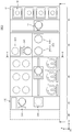
도 1 내지 도 3은 본 발명의 일 실시예에 따른 기판 처리 장치(1)를 개략적으로 보여주는 도면으로, 도 1은 기판 처리 장치(1)를 상부에서 바라본 도면이고, 도 2는 도 1의 장치(1)를 A-A 방향에서 바라본 도면이고, 도 3은 도 1의 기판 처리 장치(1)를 B-B 방향에서 바라본 도면이다.1 to 3 schematically show a substrate processing apparatus 1 according to an embodiment of the present invention. FIG. 1 is a top view of the substrate processing apparatus 1, and FIG. 2 is an apparatus of FIG. (1) is a view seen from the AA direction, and FIG. 3 is a view seen from the BB direction of the substrate processing apparatus 1 of FIG.
도 1 내지 도 3을 참조하면, 기판 처리 설비(1000)는 인덱스부(10), 공정 처리부(40), 버퍼부(30) 그리고 인터페이스부(50)를 포함할 수 있다. 1 to 3, the
인덱스부(10), 버퍼부(30), 공정 처리부(40) 그리고 인터페이스부(50)는 일렬로 배치될 수 있다. 이하, 인덱스부(10), 버퍼부(30), 공정 처리부(40) 그리고 인터페이스부(50)가 배열된 방향을 제 1 방향이라 하고, 상부에서 바라볼 때, 제 1 방향의 수직인 방향을 제 2 방향이라 하며, 제 1 방향과 제2 방향을 포함한 평면에 수직인 방향을 제 3 방향이라 정의한다. The
기판(W)은 용기(16) 내에 수납된 상태로 이동된다. 이때 용기(16)는 외부로부터 밀폐될 수 있는 구조를 가진다. 예컨대, 용기(16)로는 전방에 도어를 가지는 전면 개방 일체식 포드(Front Open Unified Pod; FOUP)가 사용될 수 있다. The substrate W is moved in the state accommodated in the
이하 도 1 내지 도 3을 참조하여, 각각의 구성에 대해서 상세히 설명한다.Hereinafter, each configuration will be described in detail with reference to FIGS. 1 to 3.
(인덱스부)(Index part)
인덱스부(10)는 기판 처리 설비(1000)의 제 1 방향의 전방에 배치된다. 일 예로, 인덱스부(10)는 4개의 로드 포트(12) 및 1개의 인덱스 로봇(13)을 포함할 수 있다. The
4개의 로드 포트(12)는 제 1 방향으로 인덱스부(10)의 전방에 배치된다. 로드 포트(12)는 복수 개가 제공되며, 이들은 제 2 방향을 따라 배치된다. 로드 포트(12)의 개수는 기판 처리 설비(1000)의 공정 효율 및 풋 프린트 조건에 따라 증가하거나 감소할 수도 있다. 로드 포트(12)들에는 공정에 제공될 기판(W) 및 공정처리가 완료된 기판(W)이 수납된 용기(16)(예컨대, 카세트, FOUP등)가 안착된다. Four
인덱스 로봇(13)은 로드 포트(12)와 이웃하여 제 1 방향으로 배치된다. 인덱스 로봇(13)은 로드 포트(12)와 버퍼부(30) 사이에 설치된다. 인덱스 로봇(13)은 버퍼부(30)와 로드 포트(12) 간에 기판을 이송한다. 버퍼부(30)의 버퍼 모듈에 대기하는 기판(W)을 용기(16)로 이송하거나, 용기(16)에서 대기하는 기판(W)을 버퍼부(30)의 버퍼 모듈로 이송한다. The
(공정처리부)(Process Processing Unit)
공정 처리부(40)에서는 노광 공정 전에 기판(W) 상에 포토 레지스트를 도포하는 공정과 노광 공정 후에 기판(W)을 현상하는 공정이 진행될 수 있다. In the
공정 처리부(40)는 도포 처리부(401)와 현상 처리부(402)을 가진다. 도포 처리부(401)와 현상 처리부(402)는 서로 간에 층으로 구획되도록 배치될 수 있다. 일 예에 의하면, 도포 처리부(401)는 현상 처리부(402)의 상부에 위치될 수 있다. 그러나, 이와 달리, 처리가 이루어지는 기판의 종류 및 처리 공정에 따라 각 처리부의 위치 및 각 처리부에 제공되는 프로세스 모듈의 종류는 이와 상이할 수 있다.The
도포 처리부(401)는 웨이퍼(W)에 대해 포토레지스트와 같은 감광액을 도포하는 공정 및 레지스트 도포 공정 전후에 웨이퍼(W)에 대해 가열 및 냉각과 같은 열처리 공정을 포함한다. 도포 처리부(401)는 레지스트 도포 챔버(410), 베이크 챔버(420), 그리고 반송 챔버(430)를 포함할 수 있다. The
레지스트 도포 챔버(410), 반송 챔버(430) 그리고 베이크 챔버(420)는 제 2 방향(14)을 따라 순차적으로 배치될 수 있다. 따라서 레지스트 도포 챔버(410)와 베이크 챔버(420)는 반송 챔버(430)를 사이에 두고 제 2 방향(14)으로 서로 이격되게 위치될 수 있다. 레지스트 도포 챔버(410)는 복수 개가 제공되며, 제 1 방향(12) 및 제 3 방향(16)으로 각각 복수 개씩 제공될 수 있다. 도면에서는 9개의 레지스트 도포 챔버(410)가 제공된 예가 도시되었으나 이에 한정되는 것은 아니다. 베이크 챔버(420)는 제 1 방향(12) 및 제 3 방향(16)으로 각각 복수 개씩 제공될 수 있다. 도면에서는 6개의 베이크 챔버(420)가 제공된 예가 도시되었으나 이에 한정되는 것은 아니다. The resist
반송 챔버(430)는 버퍼부(30)의 제 1 버퍼(320)와 제 1 방향(12)으로 나란하게 위치된다. 반송 챔버(430) 내에는 도포부 로봇(432)과 가이드 레일(433)이 위치된다. 반송 챔버(430)는 대체로 직사각의 형상을 가진다. 도포부 로봇(432)은 베이크 챔버들(420), 레지스트 도포 챔버들(400), 버퍼부(300)의 제 1 버퍼(320), 그리고 후술하는 제 2 버퍼 모듈(500)의 제 1 냉각 챔버(520) 간에 웨이퍼(W)를 이송한다. 가이드 레일(433)은 그 길이 방향이 제 1 방향(12)과 나란하도록 배치된다. 가이드 레일(433)은 도포부 로봇(432)이 제 1 방향(12)으로 직선 이동되도록 안내한다. 도포부 로봇(432)은 핸드(434)를 포함하며, 이 핸드(434)는 버퍼 반송 로봇의 제1핸드와 동일한 형태일 수 있다.The
레지스트 도포 챔버들(410)은 모두 동일한 구조를 가진다. 다만, 각각의 레지스트 도포 챔버(410)에서 사용되는 포토 레지스트의 종류는 서로 상이할 수 있다. 일 예로서 포토 레지스트로는 화학 증폭형 레지스트(chemical amplification resist)가 사용될 수 있다. 레지스트 도포 챔버(410)는 웨이퍼(W) 상에 포토 레지스트를 도포한다. 레지스트 도포 챔버(410)는 하우징(411), 지지 플레이트(412), 그리고 노즐(413)을 가진다. 하우징(411)은 상부가 개방된 컵 형상을 가진다. 지지 플레이트(412)는 하우징(411) 내에 위치되며, 웨이퍼(W)를 지지한다. 지지 플레이트(412)는 회전 가능하게 제공된다. 노즐(413)은 지지 플레이트(412)에 놓인 웨이퍼(W) 상으로 포토 레지스트를 공급한다. 노즐(413)은 원형의 관 형상을 가지고, 웨이퍼(W)의 중심으로 포토 레지스트를 공급할 수 있다. 선택적으로 노즐(413)은 웨이퍼(W)의 직경에 상응하는 길이를 가지고, 노즐(413)의 토출구는 슬릿으로 제공될 수 있다. 또한, 추가적으로 레지스트 도포 챔버(410)에는 포토 레지스트가 도포된 웨이퍼(W) 표면을 세정하기 위해 탈이온수와 같은 세정액을 공급하는 노즐(414)이 더 제공될 수 있다. The resist
베이크 챔버(420)는 웨이퍼(W)를 열처리한다. 예컨대, 베이크 챔버들(420)은 포토 레지스트를 도포하기 전에 웨이퍼(W)를 소정의 온도로 가열하여 웨이퍼(W) 표면의 유기물이나 수분을 제거하는 프리 베이크(prebake) 공정이나 포토레지스트를 웨이퍼(W) 상에 도포한 후에 행하는 소프트 베이크(soft bake) 공정 등을 수행하고, 각각의 가열 공정 이후에 웨이퍼(W)를 냉각하는 냉각 공정 등을 수행한다. 베이크 챔버(420)는 냉각 플레이트(421) 또는 가열 플레이트(422)를 가진다. 냉각 플레이트(421)에는 냉각수 또는 열전 소자와 같은 냉각 수단(423)이 제공된다. 또한 가열 플레이트(422)에는 열선 또는 열전 소자와 같은 가열 수단(424)이 제공된다. 냉각 플레이트(421)와 가열 플레이트(422)는 하나의 베이크 챔버(420) 내에 각각 제공될 수 있다. 선택적으로 베이크 챔버(420)들 중 일부는 냉각 플레이트(421)만을 구비하고, 다른 일부는 가열 플레이트(422)만을 구비할 수 있다.The
현상 모듈(402)은 웨이퍼(W) 상에 패턴을 얻기 위해 현상액을 공급하여 포토 레지스트의 일부를 제거하는 현상 공정, 및 현상 공정 전후에 웨이퍼(W)에 대해 수행되는 가열 및 냉각과 같은 열처리 공정을 포함한다. 현상모듈(402)은 현상 챔버(460), 베이크 챔버(470), 그리고 반송 챔버(480)를 가진다. 현상 챔버(460), 베이크 챔버(470), 그리고 반송 챔버(480)는 제 2 방향(14)을 따라 순차적으로 배치된다. 따라서 현상 챔버(460)와 베이크 챔버(470)는 반송 챔버(480)를 사이에 두고 제 2 방향(14)으로 서로 이격되게 위치된다. 현상 챔버(460)는 복수개가 제공되며, 제 1 방향(12) 및 제 3 방향(16)으로 각각 복수 개씩 제공된다. 도면에서는 6개의 현상 챔버(460)가 제공된 예가 도시되었다. 베이크 챔버(470)는 제 1 방향(12) 및 제 3 방향(16)으로 각각 복수 개씩 제공된다. 도면에서는 6개의 베이크 챔버(470)가 제공된 예가 도시되었다. 그러나 이와 달리 베이크 챔버(470)는 더 많은 수로 제공될 수 있다. The developing
반송 챔버(480)는 버퍼부(300)의 제 2 버퍼(330)와 제 1 방향(12)으로 나란하게 위치된다. 반송 챔버(480) 내에는 현상부 로봇(482)과 가이드 레일(483)이 위치된다. 반송 챔버(480)는 대체로 직사각의 형상을 가진다. 현상부 로봇(482)은 베이크 챔버들(470), 현상 챔버들(460), 버퍼부(300)의 제 2 버퍼(330)와 냉각 챔버(350), 그리고 제 2 버퍼 모듈(500)의 제 2 냉각 챔버(540) 간에 웨이퍼(W)를 이송한다. 가이드 레일(483)은 그 길이 방향이 제 1 방향(12)과 나란하도록 배치된다. 가이드 레일(483)은 현상부 로봇(482)이 제 1 방향(12)으로 직선 이동되도록 안내한다. 현상부 로봇(482)은 핸드(484)를 포함한다. 이 핸드(484)는 버퍼 반송 로봇의 제1핸드와 동일한 형태일 수 있다.The
현상 챔버들(460)은 모두 동일한 구조를 가진다. 다만, 각각의 현상 챔버(460)에서 사용되는 현상액의 종류는 서로 상이할 수 있다. 현상 챔버(460)는 웨이퍼(W) 상의 포토 레지스트 중 광이 조사된 영역을 제거한다. 이때, 보호막 중 광이 조사된 영역도 같이 제거된다. 선택적으로 사용되는 포토 레지스트의 종류에 따라 포토 레지스트 및 보호막의 영역들 중 광이 조사되지 않은 영역만이 제거될 수 있다. The developing
현상 챔버(460)는 하우징(461), 지지 플레이트(462), 그리고 노즐(463)을 가진다. 하우징(461)은 상부가 개방된 컵 형상을 가진다. 지지 플레이트(462)는 하우징(461) 내에 위치되며, 웨이퍼(W)를 지지한다. 지지 플레이트(462)는 회전 가능하게 제공된다. 노즐(463)은 지지 플레이트(462)에 놓인 웨이퍼(W) 상으로 현상액을 공급한다. 노즐(463)은 원형의 관 형상을 가지고, 웨이퍼(W)의 중심으로 현상액 공급할 수 있다. 선택적으로 노즐(463)은 웨이퍼(W)의 직경에 상응하는 길이를 가지고, 노즐(463)의 토출구는 슬릿으로 제공될 수 있다. 또한, 현상 챔버(460)에는 추가적으로 현상액이 공급된 웨이퍼(W) 표면을 세정하기 위해 탈이온수와 같은 세정액을 공급하는 노즐(464)이 더 제공될 수 있다.The developing
베이크 챔버(470)는 웨이퍼(W)를 열처리한다. 예컨대, 베이크 챔버들(470)은 현상 공정이 수행되기 전에 웨이퍼(W)를 가열하는 포스트 베이크 공정 및 현상 공정이 수행된 후에 웨이퍼(W)를 가열하는 하드 베이크 공정 및 각각의 베이크 공정 이후에 가열된 기판을 냉각하는 냉각 공정 등을 수행한다. 베이크 챔버(470)는 냉각 플레이트(471) 또는 가열 플레이트(472)를 가진다. 냉각 플레이트(471)에는 냉각수 또는 열전 소자와 같은 냉각 수단(473)이 제공된다. 또는 가열 플레이트(472)에는 열선 또는 열전 소자와 같은 가열 수단(474)이 제공된다. 냉각 플레이트(471)와 가열 플레이트(472)는 하나의 베이크 챔버(470) 내에 각각 제공될 수 있다. 선택적으로 베이크 챔버(470)들 중 일부는 냉각 플레이트(471)만을 구비하고, 다른 일부는 가열 플레이트(472)만을 구비할 수 있다.The
상술한 바와 같이 공정 처리부(40)에서 도포 모듈(401)과 현상 모듈(402)은 서로 간에 분리되도록 제공 된다. 또한, 상부에서 바라볼 때 도포 모듈(401)과 현상 모듈(402)은 동일한 챔버 배치를 가질 수 있다.As described above, the
(인터페이스부)(Interface part)
인터페이스부(50)는 공정 처리부(40)와 노광 장치(90) 간에 기판을 이송한다. 인터페이스부(50)는 인터페이스 로봇(510) 및 기판이 일시적으로 대기하는 버퍼 모듈(520)들이 제공될 수 있다.The
(버퍼부)(Buffer section)
도 4는 버퍼부를 설명하기 위한 도면이다.4 is a diagram for explaining a buffer unit.
도 1 내지 도 4를 참조하면, 버퍼부(30)는 인덱스부(10)와 공정 처리부(40) 사이에 위치된다. 버퍼부(30)는 버퍼 모듈(310), 쿨링 모듈(320), 가열 모듈(330) 그리고 버퍼 반송 로봇(340)을 포함할 수 있다.1 to 4, the
버퍼 모듈(310)은 인덱스부(10)와 버퍼부(30) 간의 기판 반송에 사용되도록 배치되는 제1버퍼 모듈(310-1)과, 버퍼부(30)와 공정 처리부(40) 간의 기판 반송에 사용되도록 배치되는 제2버퍼 모듈(310-2)을 포함할 수 있다. The
제1버퍼 모듈(310-1)은 인덱스부(10)의 인덱스 로봇(13)이 접근 가능한 높이(동일 높이)에 배치되고, 제2버퍼 모듈(310-2)은 도포 처리부(401)의 로봇(432)이 접근 가능한 높이(동일 높이)에 배치될 수 있으며, 쿨링 모듈(320)은 현상 처리부의 로봇(482)이 접근 가능한 높이(동일 높이)에 배치될 수 있다. The first buffer module 310-1 is disposed at a height (same height) accessible by the
도 5는 도 4에 도시된 가열 모듈을 설명하기 위한 도면이다.5 is a view for explaining the heating module shown in FIG.
도 5를 참조하면, 가열 모듈(330)은 가열 플레이트(332)와 업/다운 타입의 기판 지지핀(334)들을 포함할 수 있다. 업/다운 타입의 기판 지지핀(334)들은 반도체 분야에서 일반적으로 사용되는 리프트 핀 어셈블리이며, 이에 대한 상세한 설명은 생략한다. 가열 모듈(330)은 인덱스부(10)에서 공정 처리부(40)로 기판을 반입하기 전에 열처리하는 베이크 공정(예를 들면, CLPH,PEB))을 수행할 수 있다. Referring to FIG. 5, the
도 6은 도 4에 도시된 제1버퍼 모듈을 설명하기 위한 도면이다.FIG. 6 is a diagram for describing the first buffer module illustrated in FIG. 4.
도 6을 참조하면, 제1버퍼 모듈(310-1)은 베이스 플레이트(312)와 고정 타입의 기판 지지핀(314)들을 포함할 수 있다. 기판 지지핀(314)들이 설치된 베이스 플레이트(312)들은 다단으로 적층 배치될 수 있다. Referring to FIG. 6, the first buffer module 310-1 may include a
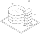
도 7은 도 4에 도시된 쿨링 모듈을 설명하기 위한 도면이다.7 is a view for explaining the cooling module shown in FIG.
도 7을 참조하면, 쿨링 모듈(320)은 수냉식 냉각 플레이트(WCP;이하 냉각 플레이트라고 함)(322)를 포함할 수 있다. 냉각 플레이트(322)에는 기판이 직접 놓여진다. 냉각 플레이트(322)에는 기판(W)이 놓여진다. 냉각 플레이트(322)는 내부에 냉각 부재(미도시됨)를 제공한다. 냉각 부재는 냉각 플레이트(322)에 놓인 기판(W)을 냉각 할 수 있는 냉각 유로를 포함할 수 있다. 냉각 플레이트(322)는 상부에서 바라볼 때, 원형의 형상으로 제공된다. 냉각 플레이트(322)는 기판(W)과 상응하는 크기로 제공될 수 있다. 냉각 플레이트(322)에는 홀들이 형성될 수 있다. 홀들은 냉각 플레이트(322) 상에 기판(W)이 놓일 시 통풍을 통한 자연 냉각을 위해 제공될 수 있다. 냉각 플레이트(322)는 복수개 제공된다. 각각의 냉각 플레이트(322)는 적층되며 이격되어 위치한다. 각각의 냉각 플레이트(322)는 지지블럭(324)에 고정결합된다. 각각의 냉각 플레이트(322)는 서로 동일한 크기로 제공될 수 있다. 각각의 냉각 플레이트(322)는 서로 동일한 높이로 이격되어 제공될 수 있다. Referring to FIG. 7, the
도시하지 않았지만, 제2버퍼 모듈(310-2)은 냉각 플레이트와 업/다운 타입의 기판 지지핀들을 포함할 수 있으며, 기판은 업/다운 타입의 기판 지지핀들에 의해 냉각 플레이트에 로딩 언로딩 될 수 있다. Although not shown, the second buffer module 310-2 may include a cooling plate and up / down type substrate support pins, and the substrate may be loaded and unloaded onto the cooling plate by up / down type substrate support pins. Can be.
도 8은 도 4에 도시된 버퍼 반송 로봇을 보여주는 도면이고, 도 9는 제1핸드를 설명하기 위한 도면이며, 도 10은 제2핸드를 설명하기 위한 도면이다.FIG. 8 is a diagram illustrating a buffer carrier robot shown in FIG. 4, FIG. 9 is a diagram for describing a first hand, and FIG. 10 is a diagram for explaining a second hand.
도 8 내지 도 10을 참조하면, 버퍼 반송 로봇(340)은 받침대(342), 지지 축(344), 베이스(346), 제 1 핸드(350), 제 2 핸드(360) 및 반송 제어부(370)를 포함한다. 8 to 10, the
받침대(342)는 일방향으로 이동 가능할 수 있다. 지지 축(344)은 받침대(342)에 고정 결합된다. 베이스(346)는 지지 축(344)의 상면에 위치된다. 베이스(346)는 축 회전이 가능하도록 지지 축(344)에 결합될 수 있다. 베이스(346)는 지지 축(344)에 대해 제3방향(16)을 중심으로 축 회전될 수 있다. 베이스(346)는 대체로 직육면체 형상을 가지도록 제공된다. 베이스(346)는 그 길이방향이 수평방향을 향하도록 제공된다. The
제 1 핸드(350) 및 제 2 핸드(360)는 베이스(3460) 상에 설치되어 전진 또는 후진 방향으로 이동 가능하도록 제공된다. 제 1 핸드(350)는 제 2 핸드(360) 보다 위에 위치될 수 있다. 구동부재(미도시)는 제 1 핸드(350) 및 제 2 핸드(360)를 전진 또는 후진 이동시킨다. The
제 1 핸드(350)와 제 2 핸드(360)는 서로 다른 재질로 구성될 수 있다. 예를 들어 제 1 핸드(350)는 가공이 비교적 수월하고 외부 충격에 쉽게 파손되지 않는 재질을 포함하고, 제 2 핸드(360)는 제 1 핸드(350)의 재질에 비해 비교적 고온의 환경에서 사용이 가능하며 핸드의 두께를 최소화할 수 있는 재질을 포함할 수 있다. 바람직하게, 제 1 핸드(350)는 알루미늄 재질을 포함하고, 제 2 핸드(360)는 세라믹 재질을 포함할 수 있다.The
상기와 같이, 서로 다른 재질로 구성된 2개의 핸드를 갖는 버퍼 반송 로봇은 일반적인 반송 환경에서는 제1핸드를 사용하여 기판을 반송한다. 그리고 특수한 경우에는 제2핸드를 사용하여 기판을 반송한다. 예를 들어, 버퍼 반송 로봇이 제2핸드 타입으로만 구성될 경우, 플레이트 형태의 버퍼에는 기판을 전달할 수 없고, 리프트 핀 타입의 버퍼를 배치해야 한다. 하지만, 쿨링 모듈의 경우 플레이트 형태의 버퍼 구조를 갖고 있기 때문에 쿨링 모듈을 리프트 핀 타입으로 변경해야 하는 문제점이 발생된다.(리프트 핀의 업다운 공간을 확보해야 하기 때문에 쿨링 모듈이 비약적으로 커짐) 그러나, 본 발명은 서로 다른 타입의 핸드를 구비하고 있어서 쿨링 모듈을 변경하지 않고 필요에 따라 선택적으로 가장 적합한 타입의 핸드를 사용할 수 있다.As described above, the buffer transfer robot having two hands made of different materials conveys the substrate using the first hand in a general transfer environment. And in a special case, a board | substrate is conveyed using a 2nd hand. For example, when the buffer transfer robot is configured only with the second hand type, the substrate cannot be transferred to the plate-type buffer, and the buffer of the lift pin type must be disposed. However, since the cooling module has a plate-shaped buffer structure, there is a problem in that the cooling module needs to be changed to a lift pin type. (The cooling module is dramatically increased because the space for the lift pin needs to be secured.) The present invention is provided with different types of hands so that the most suitable type of hand can be selectively used as needed without changing the cooling module.
도 9에서와 같이, 제 1 핸드(350)는 기판의 직경보다 큰 내경을 갖고 원주의 일부가 절곡된 환형의 링 형상을 갖는 프레임(352)과 프레임(352)로부터 그 내측으로 연장되고 기판의 가장자리 영역을 지지하는 복수개의 지지돌기(354)를 포함할 수 있다. 지지돌기(354)에는 진공 흡착 패드(356)가 제공된다. 제 1 핸드 타입은 리프트 핀이 구비된 모듈에서의 기판 반송이 가능할 뿐만 아니라 도 7에서와 같이 쿨링 모듈에서도 기판을 직접 플레이트에 올려놓을 수 있다. 다만, 제 1 핸드는 고온의 환경에 놓이게 되면 알루미늄 변형이 일어나 정밀하게 기판을 반송할 수 없기 때문에 고온의 환경에서는 세라믹 소재의 제 2 핸드를 사용하면 된다. As shown in FIG. 9, the
도 10에서와 같이, 제 2 핸드(360)는 한 쌍의 핑거부(362)가 형성된 블레이드 본체(364)를 포함할 수 있다. 블레이드 본체(364)의 상면에는 3개의 진공 흡착 패드(366)가 설치될 수 있다. 제 2 핸드(360)는 블레이드 타입이라 하며, 이러한 블레이드 타입의 핸드는 리프트 핀이 구비된 모듈에서만 기판 로딩/언로딩이 가능하며, 도 7에서와 같은 쿨링 모듈에서는 기판 반송이 불가능하다. 한편, 세라믹 소재의 제 2 핸드는 두께를 얇게 가공할 수 있고, 고온의 환경에서도 변형이 거의 없기 때문에 가열 모듈에서의 기판 반송에 적합하다. As shown in FIG. 10, the
반송 제어부(370)는 기판 반송 유닛(340)의 반송 동작을 제어한다. 일 실시 예에 따르면, 반송 제어부(370)는 구동부재(미도시됨)를 제어한다. 반송 제어부(370)는 제 1 핸드(350) 및 제 2 핸드(360)가 기판을 픽업 또는 플레이스 다운할 때, 홈 위치에 있는 제 1 핸드(350) 및 제 2 핸드(360)를 설정 위치로 이동시키고, 이를 다시 후진시켜 홈 위치로 이동시킨다.The
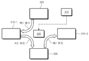
도 11을 참조하면, 반송 제어부(370)는 제1,2버퍼 모듈(310-1,310-2), 쿨링 모듈(320) 및 가열모듈(330) 각각에서의 기판 반송시 기판의 가열 유무(반송 환경의 온도)에 따라 제 1 핸드(350)와 제 2 핸드(360)를 선택적으로 사용하도록 기판 반송 유닛(340)을 제어할 수 있다. 바람직하게, 반송 제어부(370)는 가열 모듈(330)로부터 기판 반입/반출은 고온의 환경에 노출되기 때문에 세라믹 소재인 제 2 핸드(360)에 의해 수행되도록 제어할 수 있다. 그리고 반송 제어부(370)는 쿨링 모듈(320)로부터 기판 반출은 제 1 핸드(350)에 의해 수행되도록 제어할 수 있다. 그리고 반송 제어부(370)는 제1,2버퍼 모듈(310-1,310-2)로부터 기판 반입/반출은 제 1 핸드(350)와 제 2 핸드(360) 중 어느 하나에 의해 수행되도록 기판 반송 유닛을 제어할 수 있으나, 기판이 가열 모듈로 반송되는 경우에는 제2핸드에 ㅇ의해 수행되도록 제어하는 것이 바람직하다.Referring to FIG. 11, the
도 12는 변형예에 따른 버퍼부를 보여주는 도면이다.12 is a view showing a buffer unit according to a modification.
도 12를 참조하면, 변형예에 따른 버퍼부(30a)는 버퍼 모듈(310a), 쿨링 모듈(도면 편의상 생략됨), 가열 모듈(330a) 그리고 버퍼 반송 로봇(340a)을 포함하며, 이들은 도 1에 도시된 버퍼부(30)의 구성들과 대체로 유사한 구성과 기능으로 제공됨으로, 이하에서는 차이점을 위주로 변형예를 설명하기로 한다.Referring to FIG. 12, the buffer unit 30a according to the modification includes a buffer module 310a, a cooling module (not shown for convenience of illustration), a heating module 330a, and a buffer transfer robot 340a, which are illustrated in FIG. 1. Since it is provided in a substantially similar configuration and function to the configuration of the
본 변형예에서 버퍼부(30a)는 인덱스부(10)와 공정 처리부(40) 사이에 하나의 버퍼 모듈(310a)이 배치된 형태로 제공될 수 있다. 이처럼, 버퍼부(30a)는 공정 처리가 이루어지는 기판의 종류 및 처리 공정에 따라 버퍼 모듈의 위치 및 개수는 변경될 수 있다.In the present modification, the buffer unit 30a may be provided in a form in which one buffer module 310a is disposed between the
이상의 설명은 본 발명의 기술 사상을 예시적으로 설명한 것에 불과한 것으로서, 본 발명이 속하는 기술 분야에서 통상의 지식을 가진 자라면 본 발명의 본질적인 특성에서 벗어나지 않는 범위에서 다양한 수정 및 변형이 가능할 것이다. 따라서, 본 발명에 개시된 실시 예들은 본 발명의 기술 사상을 한정하기 위한 것이 아니라 설명하기 위한 것이고, 이러한 실시 예에 의하여 본 발명의 기술 사상의 범위가 한정되는 것은 아니다. 본 발명의 보호 범위는 아래의 청구범위에 의하여 해석되어야 하며, 그와 동등한 범위 내에 있는 모든 기술 사상은 본 발명의 권리범위에 포함되는 것으로 해석되어야 할 것이다.The above description is merely illustrative of the technical idea of the present invention, and those skilled in the art may make various modifications and changes without departing from the essential characteristics of the present invention. Therefore, the embodiments disclosed in the present invention are not intended to limit the technical idea of the present invention but to describe the present invention, and the scope of the technical idea of the present invention is not limited thereto. The scope of protection of the present invention should be interpreted by the following claims, and all technical ideas within the scope equivalent thereto should be construed as being included in the scope of the present invention.
10: 인덱스부
30 : 버퍼부
40 : 공정 처리부
50 : 인터페이스부
310 : 버퍼 모듈
320 : 쿨링 모듈
330 : 가열 모듈
340 : 버퍼 반송 로봇 10: index portion 30: buffer portion
40
310: buffer module 320: cooling module
330: heating module 340: buffer transport robot
Claims (16)
기판 처리를 수행하는 처리실들이 적층되어 배치되는 공정 처리부;
상기 공정 처리부와 상기 인덱스부 사이에 배치되는 버퍼부를 포함하되;
상기 버퍼부는
버퍼 모듈, 쿨링 모듈, 가열모듈 그리고 상기 버퍼 모듈, 상기 쿨링 모듈 및 상기 가열모듈에 접근 가능한 이동 통로상에 배치되며 서로 다른 재질로 구성된 제1핸드와 제2핸드를 갖는 버퍼 반송 로봇을 포함하는 기판 처리 설비.Index unit;
A process processor configured to stack process chambers performing substrate processing;
A buffer unit disposed between the process processing unit and the index unit;
The buffer unit
A substrate including a buffer module, a cooling module, a heating module, and a buffer transfer robot having a first hand and a second hand made of different materials and disposed on a moving passage accessible to the buffer module, the cooling module, and the heating module. Processing equipment.
상기 제1핸드는 알루미늄 재질로 이루어지고,
상기 제2핸드는 세라믹 재질로 이루어지는 기판 처리 설비.The method of claim 1,
The first hand is made of aluminum,
And the second hand is made of a ceramic material.
상기 제 1 핸드 및 상기 제 2 핸드는 서로 상하 방향으로 배열되는 기판 처리 설비.The method of claim 2,
And the first hand and the second hand are arranged in a vertical direction with each other.
상기 제2핸드는 상기 제1핸드 아래에 배치되는 기판 처리 설비.The method of claim 2,
And the second hand is disposed below the first hand.
상기 기판 반송 유닛의 반송 동작을 제어하는 반송 제어부를 포함하되;
상기 반송 제어부는
상기 버퍼 모듈, 상기 쿨링 모듈 및 상기 가열모듈 각각에서의 기판 반송시 기판의 가열 유무에 따라 상기 제1핸드와 상기 제2핸드를 선택적으로 사용하도록 상기 기판 반송 유닛을 제어하는 기판 처리 설비.The method of claim 2,
A conveying control unit controlling a conveying operation of the substrate conveying unit;
The conveying control unit
And a substrate transfer unit to control the substrate transfer unit to selectively use the first hand and the second hand depending on whether the substrate is heated in the buffer module, the cooling module, and the heating module.
상기 반송 제어부는
상기 가열 모듈로부터 기판 반입/반출은 상기 제2핸드에 의해 수행되도록 그리고 상기 쿨링 모듈로부터 기판 반입/반출은 상기 제1핸드에 의해 수행되도록 그리고 상기 버퍼 모듈로부터 기판 반입/반출은 상기 제1핸드와 상기 제2핸드 중 어느 하나에 의해 수행되도록 상기 기판 반송 유닛을 제어하는 기판 처리 설비.The method of claim 5, wherein
The conveying control unit
Substrate import / export from the heating module is performed by the second hand and substrate import / export from the cooling module is performed by the first hand and substrate import / export from the buffer module is performed with the first hand. A substrate processing apparatus for controlling the substrate transfer unit to be performed by any one of the second hands.
상기 제1핸드는
기판의 직경보다 큰 내경을 갖고 원주의 일부가 절곡된 환형의 링 형상을 갖는 베이스; 및
상기 베이스로부터 그 내측으로 연장되고 기판의 가장자리 영역을 지지하는 복수개의 지지돌기를 포함하는 기판 처리 설비.The method of claim 5, wherein
The first hand
A base having an inner diameter larger than the diameter of the substrate and having an annular ring shape in which a portion of the circumference is bent; And
And a plurality of support protrusions extending inwardly from the base and supporting edge regions of the substrate.
상기 제2핸드는
한 쌍의 핑거부가 형성된 블레이드 본체를 포함하는 기판 처리 설비.The method of claim 5, wherein
The second hand
Substrate processing equipment comprising a blade body formed with a pair of fingers.
상기 버퍼 모듈은 고정 타입의 기판 지지핀들을 포함하고,
상기 가열 모듈은 업/다운 타입의 기판 지지핀들을 포함하며,
상기 쿨링 모듈은 기판이 직접 놓여지는 냉각 플레이트를 포함하는 기판 처리 설비.The method of claim 5, wherein
The buffer module includes a fixed type substrate support pins,
The heating module includes up / down type substrate support pins,
The cooling module includes a cooling plate on which the substrate is directly placed.
상기 버퍼 모듈은 상기 인덱스부와 상기 버퍼부 간의 기판 반송에 사용되도록 배치되는 제1버퍼 모듈; 및
상기 버퍼부와 상기 공정 처리부 간의 기판 반송에 사용되도록 배치되는 제1버퍼 모듈을 포함하는 기판 처리 설비. The method of claim 5, wherein
The buffer module may include a first buffer module disposed to be used to transport a substrate between the index unit and the buffer unit; And
And a first buffer module arranged to be used for transferring the substrate between the buffer unit and the process unit.
상기 버퍼 모듈은 상기 인덱스부와 상기 버퍼부 간의 기판 반송과 상기 버퍼부와 상기 공정 처리부 간의 기판 반송에 모두 사용되도록 배치되는 기판 처리 설비.The method of claim 5, wherein
And the buffer module is arranged to be used for both substrate transfer between the index unit and the buffer unit and substrate transfer between the buffer unit and the process processor.
상기 공정 처리부는 도포 공정 처리를 수행하기 위한 도포부와, 현상 공정 처리를 수행하기 위한 현상부가 층으로 구획되도록 적층되어 배치되고,
상기 버퍼 모듈과 상기 가열 모듈은 상기 도포부와 동일 높이에 배치되고,
상기 쿨링 모듈은 상기 현상부와 동일 높이에 배치되는 기판 처리 설비.The method of claim 5, wherein
The process processing unit is disposed in such a way that the coating unit for performing the coating process treatment and the developing unit for performing the developing process treatment are stacked so as to be divided into layers.
The buffer module and the heating module is disposed at the same height as the applicator,
And the cooling module is disposed at the same height as the developing part.
상기 제1핸드와 상기 제2핸드는 서로 다른 재질로 구성된 기판 반송 로봇.A first hand and a second hand, each of which can be independently driven and can be selectively used according to the use environment,
And the first hand and the second hand are made of different materials.
상기 제1핸드는
기판의 직경보다 큰 내경을 갖고 원주의 일부가 절곡된 환형의 링 형상을 갖는 베이스; 및
상기 베이스로부터 그 내측으로 연장되고 기판의 가장자리 영역을 지지하는 복수개의 지지돌기를 포함하고,
상기 제2핸드는
한 쌍의 핑거부가 형성된 블레이드 본체를 포함하는 기판 반송 로봇.The method of claim 13,
The first hand
A base having an inner diameter larger than the diameter of the substrate and having an annular ring shape in which a portion of the circumference is bent; And
A plurality of support protrusions extending inwardly from the base and supporting edge regions of the substrate;
The second hand
A substrate transfer robot comprising a blade body formed with a pair of fingers.
상기 베이스는 알루미늄 재질로 이루어지고,
상기 블레이드 본체는 세라믹 재질로 이루어지는 기판 반송 로봇.The method of claim 13,
The base is made of aluminum,
The blade body is a substrate transfer robot made of a ceramic material.
상기 제1핸드는 상온 상태의 기판을 반송하는데 사용되고,
상기 제2핸드는 고온 환경에서의 기판 반송에 하는데 사용되는 기판 반송 로봇.The method of claim 13,
The first hand is used to convey the substrate in a room temperature state,
The said 2nd hand is a board | substrate conveyance robot used for conveying a board | substrate in a high temperature environment.
Priority Applications (1)
| Application Number | Priority Date | Filing Date | Title |
|---|---|---|---|
| KR1020180104667A KR102175077B1 (en) | 2018-09-03 | 2018-09-03 | Transfer robot and Apparatus for treating substrate with the robot |
Applications Claiming Priority (1)
| Application Number | Priority Date | Filing Date | Title |
|---|---|---|---|
| KR1020180104667A KR102175077B1 (en) | 2018-09-03 | 2018-09-03 | Transfer robot and Apparatus for treating substrate with the robot |
Publications (2)
| Publication Number | Publication Date |
|---|---|
| KR20200026563A true KR20200026563A (en) | 2020-03-11 |
| KR102175077B1 KR102175077B1 (en) | 2020-11-05 |
Family
ID=69809718
Family Applications (1)
| Application Number | Title | Priority Date | Filing Date |
|---|---|---|---|
| KR1020180104667A KR102175077B1 (en) | 2018-09-03 | 2018-09-03 | Transfer robot and Apparatus for treating substrate with the robot |
Country Status (1)
| Country | Link |
|---|---|
| KR (1) | KR102175077B1 (en) |
Cited By (1)
| Publication number | Priority date | Publication date | Assignee | Title |
|---|---|---|---|---|
| KR20230059875A (en) * | 2021-10-25 | 2023-05-04 | 세메스 주식회사 | Process Block for Photolithography Instruments and Photolithography Instruments using therof |
Citations (5)
| Publication number | Priority date | Publication date | Assignee | Title |
|---|---|---|---|---|
| KR20020089616A (en) * | 2001-05-23 | 2002-11-30 | 한국디엔에스 주식회사 | A spinner system in use the process of fabricating semiconductor device |
| KR20110131552A (en) * | 2010-05-31 | 2011-12-07 | 주식회사 테라세미콘 | Apparatus for transferring substrate |
| KR20150103316A (en) | 2009-03-13 | 2015-09-09 | 가와사키 쥬코교 가부시키가이샤 (디/비/에이 가와사키 헤비 인더스트리즈, 리미티드) | Robot provided with end effector, and method for operating the robot |
| KR101757819B1 (en) * | 2016-05-27 | 2017-07-14 | 세메스 주식회사 | Apparatus for treating substrate and method for treating substrate |
| KR20180006710A (en) * | 2016-07-11 | 2018-01-19 | 세메스 주식회사 | Apparatus for treating susbstrate |
-
2018
- 2018-09-03 KR KR1020180104667A patent/KR102175077B1/en active IP Right Grant
Patent Citations (5)
| Publication number | Priority date | Publication date | Assignee | Title |
|---|---|---|---|---|
| KR20020089616A (en) * | 2001-05-23 | 2002-11-30 | 한국디엔에스 주식회사 | A spinner system in use the process of fabricating semiconductor device |
| KR20150103316A (en) | 2009-03-13 | 2015-09-09 | 가와사키 쥬코교 가부시키가이샤 (디/비/에이 가와사키 헤비 인더스트리즈, 리미티드) | Robot provided with end effector, and method for operating the robot |
| KR20110131552A (en) * | 2010-05-31 | 2011-12-07 | 주식회사 테라세미콘 | Apparatus for transferring substrate |
| KR101757819B1 (en) * | 2016-05-27 | 2017-07-14 | 세메스 주식회사 | Apparatus for treating substrate and method for treating substrate |
| KR20180006710A (en) * | 2016-07-11 | 2018-01-19 | 세메스 주식회사 | Apparatus for treating susbstrate |
Cited By (1)
| Publication number | Priority date | Publication date | Assignee | Title |
|---|---|---|---|---|
| KR20230059875A (en) * | 2021-10-25 | 2023-05-04 | 세메스 주식회사 | Process Block for Photolithography Instruments and Photolithography Instruments using therof |
Also Published As
| Publication number | Publication date |
|---|---|
| KR102175077B1 (en) | 2020-11-05 |
Similar Documents
| Publication | Publication Date | Title |
|---|---|---|
| JP4464993B2 (en) | Substrate processing system | |
| US9059224B2 (en) | System and method for treating substrate | |
| KR101166109B1 (en) | Facility for treating substrates | |
| KR101930555B1 (en) | Substrate processing system, substrate processing method and storage medium for computer | |
| JP2010177673A (en) | Apparatus and method for treating substrate | |
| JP4924186B2 (en) | Coating and developing apparatus and method, and storage medium | |
| KR102315667B1 (en) | Method and Apparatus for treating substrate | |
| JP3649048B2 (en) | Resist coating / developing apparatus, and substrate heating processing apparatus and substrate transfer apparatus used therefor | |
| JP4665037B2 (en) | Substrate processing system | |
| JP3485990B2 (en) | Transfer method and transfer device | |
| KR102175077B1 (en) | Transfer robot and Apparatus for treating substrate with the robot | |
| KR102324405B1 (en) | Apparatus and Method for treating substrate | |
| KR102066044B1 (en) | Substrate treating apparatus, index robot and substrate transferring method | |
| KR102046869B1 (en) | Member for suppliyng a substrate, Buffer unit, and Apparatus for treating a substrate | |
| JP2013069874A (en) | Substrate processing system, substrate transfer method, program and computer storage medium | |
| JP4880004B2 (en) | Substrate processing system | |
| KR102204884B1 (en) | Transfer robot and Apparatus for treating substrate with the robot | |
| KR20210034337A (en) | substrate Transfer robot | |
| KR102037920B1 (en) | Heating unit | |
| KR101768518B1 (en) | Transfer chamber, Apparatus for treating substrate, and method for trasnferring substrate | |
| KR101721148B1 (en) | Nozzle, Apparatus for treating substrate and method for applying chemicals | |
| KR102298088B1 (en) | Transfer robot and Apparatus for treating substrate with the robot | |
| KR20150037453A (en) | Substrate treating apparatus | |
| KR102233465B1 (en) | Unit for transferring substrate, Apparatus and Method for treating substrate with the unit | |
| JP7025964B2 (en) | Heat treatment equipment |
Legal Events
| Date | Code | Title | Description |
|---|---|---|---|
| A201 | Request for examination | ||
| E902 | Notification of reason for refusal | ||
| E90F | Notification of reason for final refusal | ||
| E701 | Decision to grant or registration of patent right |