JP5028403B2 - Elevator equipment - Google Patents
Elevator equipment Download PDFInfo
- Publication number
- JP5028403B2 JP5028403B2 JP2008500056A JP2008500056A JP5028403B2 JP 5028403 B2 JP5028403 B2 JP 5028403B2 JP 2008500056 A JP2008500056 A JP 2008500056A JP 2008500056 A JP2008500056 A JP 2008500056A JP 5028403 B2 JP5028403 B2 JP 5028403B2
- Authority
- JP
- Japan
- Prior art keywords
- car
- cable
- traction sheave
- section
- elevator installation
- Prior art date
- Legal status (The legal status is an assumption and is not a legal conclusion. Google has not performed a legal analysis and makes no representation as to the accuracy of the status listed.)
- Expired - Fee Related
Links
Images


Classifications
-
- B—PERFORMING OPERATIONS; TRANSPORTING
- B66—HOISTING; LIFTING; HAULING
- B66B—ELEVATORS; ESCALATORS OR MOVING WALKWAYS
- B66B1/00—Control systems of elevators in general
- B66B1/02—Control systems without regulation, i.e. without retroactive action
- B66B1/06—Control systems without regulation, i.e. without retroactive action electric
- B66B1/14—Control systems without regulation, i.e. without retroactive action electric with devices, e.g. push-buttons, for indirect control of movements
-
- B—PERFORMING OPERATIONS; TRANSPORTING
- B66—HOISTING; LIFTING; HAULING
- B66B—ELEVATORS; ESCALATORS OR MOVING WALKWAYS
- B66B9/00—Kinds or types of lifts in, or associated with, buildings or other structures
Abstract
Description
本発明は、次のようなエレベータ設備に関する。即ち、シャフト内に複数のかごを備えたエレベータ設備であって、第1のかごの下側に第2のかごが配され、各々のかごに、トラクションシーブを備えた駆動部と、少なくとも1つのケーブルストランドであって、前記トラクションシーブに巻き掛けられて前記かごをカウンタウェイトに連結するものとが関連付けられており、かつ、前記第2のかごが、懸架比1:1で保持されると共に、該第2のかごの前記トラクションシーブに巻き掛けられた、前記第2のかごの異なる側面に関連付けられた2つのケーブルストランドによって該かごのカウンタウェイトに連結されるようなエレベータ設備に関する。 The present invention relates to the following elevator installation. That is, an elevator installation having a plurality of cars in a shaft, wherein a second car is arranged below the first car, and each car has a drive unit with a traction sheave, and at least one A cable strand is associated with the traction sheave that couples the car to a counterweight and the second car is held at a suspension ratio of 1: 1, It relates to an elevator installation connected to the counterweight of the car by two cable strands associated with different sides of the second car, wound around the traction sheave of the second car.
共通のシャフト内を互いに独立に昇降し得る複数のかごを使用することはエレベータ設備の処理能力の向上を可能にする。これらのかごは、かごをそれぞれのカウンタウェイトに連結するケーブルストランドが巻き掛けられるトラクションシーブによって駆動されることができる。第1のかごには単一のケーブルストランドが必要とされるだけである。第1のかごの下側に配置された第2のかごには通例2つのケーブルストランドが使用され、これらのケーブルストランドはかごの異なる2側面に配置されて、第1のかごの側方外側を走行する。US-A-5 419 414には、そのため、第2のかごの2つのケーブルストランドをそれぞれ別々のトラクションシーブに巻き掛けて、第2のかごの駆動が、駆動軸を介して共通の駆動モータに結合される、かごの幅だけ互いに離間させられた2つのトラクションシーブによって行われるようにすることが提案されている。但し、これには第2のかご用の長い駆動軸を有した別の駆動モータが必要であると共に、大きなシャフト空間も必要とされ、エレベータ設備の製造・運転コストの高まりを招く。 The use of a plurality of cars that can be lifted and lowered independently from each other in a common shaft makes it possible to improve the throughput of the elevator installation. These cars can be driven by traction sheaves around which cable strands connecting the cars to their respective counterweights are wound. Only a single cable strand is required for the first car. Two cable strands are typically used for the second car located on the underside of the first car, and these cable strands are arranged on two different sides of the car so that the side of the first car is laterally outward. Run. In US-A-5 419 414, therefore, the two cable strands of the second car are wound around different traction sheaves so that the drive of the second car is connected to a common drive motor via the drive shaft. It has been proposed to be performed by two traction sheaves that are joined and separated from each other by the width of the car. However, this requires a separate drive motor having a long drive shaft for the second car, and also requires a large shaft space, leading to an increase in manufacturing and operating costs of the elevator equipment.
EP-A-1 329 412では、第2のかごの2つのケーブルストランドを共通のトラクションシーブに巻き掛けることが提案されている。これによって、シャフト空間を節減すると共に、第2のかごの駆動に標準モータを使用することが可能になる。但し、第2のかごの2つのケーブルストランドはかごの運転中にそれぞれ別様に損耗するため、ケーブルはそれぞれ異なる時点で最大許容損耗度に達する。ケーブルストランドを交換するために、エレベータ設備は運転停止されなければならず、しかもこれらの非稼動時間をできるだけ短くするために、2つのケーブルストランドは、厳密にはより激しく損耗している方のケーブルストランドのみがこうして交換される必要があり、損耗度の低い方のケーブルストランドについては最大許容損耗度にまだ達していないにもかかわらず、同時に交換されるのが通例である。
本発明の目的は、可能な限り、第2のかごの2つのケーブルストランドが同時点にそれぞれの最大許容損耗度に達し、こうして運転コストの低下が図られるようにする、冒頭に述べたタイプのエレベータ設備を開発することである。 The object of the present invention is, as much as possible, of the type mentioned at the outset so that the two cable strands of the second car reach their maximum permissible wear at the same time, thus reducing the operating costs. It is to develop elevator equipment.
この目的は、本発明によれば、一般的なタイプのエレベータ設備において、次のようにすることで達成される。即ち、上記第2のかごに関連付けられた上記トラクションシーブが、2つのトラクションシーブ部分を有し、該トラクションシーブ部分の各々に上記第2のかごの上記2つのケーブルストランドの1つが巻き掛けられると共に、上記トラクションシーブ部分の間の距離が、上記第2のかごの領域における上記2つのケーブルストランドの間の距離よりも小さいこと、及び、本エレベータ設備が、上記第2のかごの上記2つのケーブルストランドを等しい荷重に付するケーブル案内装置を有すること、である。上記ケーブルラインの荷重は、ケーブルライン自らが受ける引張り力だけでなく、方向転換ローラ及び関連付けられた上記トラクションシーブにおけるケーブルライン自らの転向によってももたらされる。本発明によれば、上記第2のかごの上記2つのケーブルストランドが、上記ケーブル案内装置によって、ケーブルストランドがほぼ同じケーブル荷重を受けるように配置及び案内される。従って、上記2つのケーブルストランドは等しく損耗し、ほぼ同じ時点にその最大許容損耗度に達する。この時点において、双方のケーブルストランドは交換可能であると共に同じ損耗度を示す。その結果、上記ケーブルストランドの一方をその耐久寿命の終りに達する前に交換する必要はない。それ故、本発明による上記エレベータ設備は運転コストの低下によって特徴づけられる。
上記第2のかごを駆動するために、単一のトラクションシーブが使用される。このトラクションシーブに、上記第2のかごの上記2つのケーブルストランドが巻き掛けられる。上記トラクションシーブは2つのトラクションシーブ部分を有し、このトラクションシーブ部分の各々に上記第2のかごの上記2つのケーブルストランドの1つが巻き掛けられる。上記トラクションシーブ部分の間の距離は、上記第2のかごの領域における上記2つのケーブルストランドの間の距離よりも小さい。
This object is achieved according to the invention in a general type elevator installation by: That is, the traction sheave associated with the second car has two traction sheave portions, each of the traction sheave portions being wrapped with one of the two cable strands of the second car. The distance between the traction sheave portions is less than the distance between the two cable strands in the area of the second car, and the elevator installation provides the two cables of the second car Having a cable guiding device for subjecting the strands to equal loads. The load on the cable line is brought about not only by the tensile force that the cable line itself receives, but also by the turning of the cable line itself at the turning roller and the associated traction sheave. According to the invention, the two cable strands of the second car are arranged and guided by the cable guiding device so that the cable strands receive substantially the same cable load. Thus, the two cable strands wear equally and reach their maximum allowable wear at approximately the same time. At this point, both cable strands are interchangeable and exhibit the same degree of wear. As a result, it is not necessary to replace one of the cable strands before reaching the end of its endurance life. Therefore, the elevator installation according to the invention is characterized by a reduction in operating costs.
A single traction sheave is used to drive the second car. The two cable strands of the second car are wound around the traction sheave. The traction sheave has two traction sheave portions, each of which is wrapped with one of the two cable strands of the second car. The distance between the traction sheave portions is less than the distance between the two cable strands in the area of the second car.
特に、上記2つのトラクションシーブ部分が互いに接するようにしてもよい。このタイプのエレベータ設備の構成は特にコンパクトな構造形態を特徴としており、比較的小さなシャフト空間を占める。 In particular, the two traction sheave portions may be in contact with each other. The construction of this type of elevator installation is characterized by a particularly compact structure and occupies a relatively small shaft space.
上記第2のかごは懸架比1:1で保持される。つまり、上記第2のかごの上記ケーブルストランドは上記かごに固定されるため、上記2つのケーブルストランドのケーブル速度は上記かごの速度に等しい。これによって、上記第2のかごの走行騒音及び振動を抑制することが許容される。上記第1のかごも懸架比1:1で保持することができるため、本発明による上記エレベータ設備は総じて低騒音レベルによって特徴づけられる。懸架比1:1の場合、上記かごの高さの変化は、上記かごをそのカウンタウェイトに連結するそれぞれのケーブルストランドの送りに等しい。 The second car is held at a suspension ratio of 1: 1. That is, since the cable strand of the second car is fixed to the car, the cable speed of the two cable strands is equal to the speed of the car. Thereby, it is allowed to suppress the running noise and vibration of the second car. Since the first car can also be held at a suspension ratio of 1: 1, the elevator installation according to the invention is generally characterized by a low noise level. For a suspension ratio of 1: 1, the change in car height is equal to the feed of each cable strand connecting the car to its counterweight.
本発明による上記エレベータ設備において、上記第1のかご用にも、上記第2のかご用にも、標準駆動モータを使用することができる。これによって、同じく、上記エレベータ設備の製造・運転コストを低下させることが可能である。 In the elevator installation according to the present invention, a standard drive motor can be used for both the first car and the second car. This can similarly reduce the manufacturing and operating costs of the elevator equipment.
上記ケーブル案内装置が方向転換ローラを含み、上記第2のかごの上記2つのケーブルストランドが同数の方向転換ローラ及び上記第2のかごの上記トラクションシーブに巻き掛けられると有利である。各ケーブルストランドは方向転換ローラ及び上記トラクションシーブの双方にて損耗を受けるため、上記2つのケーブルストランドにつき同数の方向転換ローラを使用することで、上記ケーブルがより等しく損耗されるという効果がもたらされる。 Advantageously, the cable guiding device comprises a turning roller, and the two cable strands of the second car are wound around the same number of turning rollers and the traction sheave of the second car. Since each cable strand is subject to wear on both the diverting roller and the traction sheave, using the same number of diverting rollers for the two cable strands has the effect that the cable is more evenly worn. .
上記ケーブル案内装置が方向転換ローラを含み、隣接する2方向転換ローラ間の距離及び上記第2のかごの上記トラクションシーブとこのトラクションシーブに隣接する方向転換ローラとの間の距離が上記第2のかごの双方のケーブルストランドにつきそれぞれ一致しているのが有利である。方向転換ローラと上記トラクションシーブとに巻き掛けられた上記ケーブルストランドの損耗はそれぞれの方向転換ローラ間の距離ならびに上記方向転換ローラと上記トラクションシーブとの間の距離にも依存する。上記2つのケーブルストランドにつきこれらの距離がそれぞれ一致していれば、上記第2のかごの上記ケーブルストランドのより等しい損耗が達成され得る。 The cable guiding device includes a direction change roller, and a distance between adjacent two direction change rollers and a distance between the traction sheave of the second car and the direction change roller adjacent to the traction sheave are the second It is advantageous for both cable strands of the car to be identical. The wear of the cable strand wound around the direction change roller and the traction sheave also depends on the distance between the direction change rollers and the distance between the direction change roller and the traction sheave. If these distances are the same for the two cable strands, more equal wear of the cable strands of the second car can be achieved.
本発明の特に好ましい1実施形態において、上記ケーブル案内装置は方向転換ローラを含み、上記それぞれの方向転換ローラならびに上記トラクションシーブの箇所で生ずる方向変化の順序は上記第2のかごの上記2つのケーブルストランドにつきそれぞれ同じとされている。従って、上記方向転換ローラ及び上記トラクションシーブによって上記ケーブルストランドがそれぞれ受ける曲げ方向は上記2つのケーブルストランドにつきそれぞれ一致している。結果として、特に、双方のケーブルストランドにつき曲げ方向の変化が等しく生ずることが保証される。こうした方向変化は上記それぞれのケーブルストランドに大きな荷重をもたらす。双方のケーブルストランドにつき方向変化が一致するように保証することにより、上記ケーブルの荷重及び、従って、上記ケーブルの損耗もほぼ等しいものとすることができる。 In a particularly preferred embodiment of the invention, the cable guiding device comprises a direction change roller, the order of the direction change occurring at the respective direction change roller and at the location of the traction sheave being the two cables of the second car. Each strand is the same. Therefore, the bending directions received by the cable strands by the direction changing roller and the traction sheave are the same for the two cable strands. As a result, it is ensured in particular that the change in bending direction occurs equally for both cable strands. Such a change in direction results in a large load on each cable strand. By ensuring that the direction changes for both cable strands match, the load on the cable, and thus the wear on the cable, can be substantially equal.
上記ケーブル案内装置が方向転換ローラを含み、上記第2のかごの上記2つのケーブルストランドが互いに対応する方向転換ローラならびに上記第2のかごの上記トラクションシーブの箇所でそれぞれ同じ角度だけ転向されるのが特に有利である。例えば、上記それぞれのケーブルストランドがそれぞれ同じ角度だけ転向される方向転換ローラが上記2つのケーブルストランドの各々につき同じ高さ位置に配置され、こうして、上記ケーブルストランドがそれぞれ上記方向転換ローラならびに上記トラクションシーブの箇所で同じ荷重及び同じ損耗を受けるようにすることができる。 The cable guide device includes a direction change roller, and the two cable strands of the second car are turned by the same angle at the corresponding direction change roller and the traction sheave of the second car, respectively. Is particularly advantageous. For example, the direction change rollers in which the respective cable strands are turned by the same angle are arranged at the same height position for each of the two cable strands, and thus the cable strands are respectively the direction change roller and the traction sheave. Can be subjected to the same load and the same wear.
好ましい1実施形態において、上記第2のかごの上記2つのケーブルストランドは対称面を中心にして互いに鏡像対称的に走行する。上記2つのケーブルストランドの対称的な走行により、上記2つのケーブルストランドの特に等しい損耗を達成することが可能になる。 In a preferred embodiment, the two cable strands of the second car run mirror-symmetrically with respect to each other about a symmetry plane. The symmetrical running of the two cable strands makes it possible to achieve a particularly equal wear of the two cable strands.
上記第2のかごの上記2つのケーブルストランドの各々が、上記第2のかごから出発して第1の方向転換ローラにまで延びるケーブルストランド第1区間と、上記第1区間に接続されるケーブルストランド第2区間とを有し、上記ケーブルストランド第2区間は上記ケーブルストランド第1区間に対して垂直に並べられるのが有利である。これにより、上記第1のかごの異なる側面の脇を通過する上記2つのケーブルストランドを上記ケーブルストランド第2区間で会合させ、こうしてシャフト空間を節減することが可能である。 A first section of cable strands, each of the two cable strands of the second car extending from the second car to the first turning roller, and a cable strand connected to the first section Advantageously, the second section of the cable strand is arranged perpendicular to the first section of the cable strand. As a result, the two cable strands passing by the different side surfaces of the first car can be associated with each other in the second section of the cable strand, thus saving the shaft space.
上記ケーブルストランド第2区間は水平に並べられるのが有利である。従って、上記第2のかごの上記ケーブルストランドは上記第2のかごから延びて第1の方向転換ローラに達すると同所で90°転向される。上記第2のかごから延びる上記ケーブルストランド第1区間は垂直上方に向かって上記第1のかごの脇を走行通過し、90°転向された後、上記ケーブルストランド第1区間は水平に並べられた上記ケーブルストランド第2区間に接続される。 The cable strand second section is advantageously arranged horizontally. Thus, the cable strand of the second car is turned 90 ° at the same location as it extends from the second car and reaches the first turning roller. The first section of the cable strand extending from the second car travels along the side of the first car vertically upward and is turned by 90 °, and then the first section of the cable strand is arranged horizontally. Connected to the second section of the cable strand.
上記ケーブルストランド第2区間は第2の方向転換ローラにまで延び、同所で上記第2区間はケーブルストランド第3区間に接続されることができる。この場合、上記第2のかごの上記2つのケーブルストランドの上記ケーブルストランド第3区間は互いに平行に並べられるのが有利であり、特に、上記ケーブルストランド第3区間は垂直に並べられてよい。従って、上記第2のかごの上記2つのケーブルストランドの各々はそれぞれのケーブルストランド第3区間で垂直方向上方、又は下方に案内されることができる。 The cable strand second section extends to a second turning roller, where the second section can be connected to the cable strand third section. In this case, the cable strand third sections of the two cable strands of the second car are advantageously arranged parallel to each other, in particular the cable strand third sections may be arranged vertically. Accordingly, each of the two cable strands of the second cage can be guided vertically upward or downward in the respective cable strand third section.
本発明の好ましい1実施形態において、上記ケーブルストランド第3区間は第3の方向転換ローラ、又は上記第2のかごの上記トラクションシーブにまで延び、同所で上記第3区間はケーブルストランド第4区間に接続され、上記第2のかごの上記2つのケーブルストランドのケーブルストランド第4区間は互いに平行に並べられる。 In a preferred embodiment of the present invention, the third section of the cable strand extends to a third turning roller or the traction sheave of the second car, where the third section is the fourth section of the cable strand. The cable strand fourth sections of the two cable strands of the second car are arranged parallel to each other.
上記ケーブルストランド第4区間は上記トラクションシーブから直接、上記第2のかごの上記カウンタウェイトにまで延びることができる。この場合、上記ケーブルストランド第4区間は垂直方向に走行する。 The fourth section of the cable strand can extend directly from the traction sheave to the counterweight of the second car. In this case, the fourth section of the cable strand travels in the vertical direction.
別法として、上記ケーブルストランド第4区間は、例えば水平に並べられるようにすることができる。 Alternatively, the fourth section of the cable strand can be arranged horizontally, for example.
上記ケーブルストランド第4区間は上記第2のかごの上記トラクションシーブから第3の方向転換ローラにまで延びてよく、同所で上記ケーブルストランド第4区間はケーブルストランド第5区間に接続され、上記第2のかごの上記2つのケーブルストランドの上記ケーブルストランド第5区間は互いに平行に並べられる。特に上記ケーブルストランド第5区間は垂直に並べられるようにすることができる。 The fourth cable strand section may extend from the traction sheave of the second car to a third turning roller, where the fourth cable strand section is connected to the fifth cable strand section, The cable strand fifth sections of the two cable strands of the two cars are arranged parallel to each other. In particular, the fifth section of the cable strand can be arranged vertically.
本発明の好ましい1実施形態において、上記ケーブルストランド第5区間は上記第2のかごの上記カウンタウェイトにまで延びる。つまり、上記第2のかごの上記2つのケーブルストランドの各々は総計4回の転向を受け、各々のケーブルストランドに3方向転換ローラと、更に加えて上記第2のかごの上記共通のトラクションシーブとが使用される。 In a preferred embodiment of the invention, the fifth section of the cable strand extends to the counterweight of the second car. That is, each of the two cable strands of the second car undergoes a total of four turns, and each cable strand has a three-direction turning roller and, in addition, the common traction sheave of the second car. Is used.
本発明は上記第2のかごの上記2つのケーブルストランドにつき特定回数の転向に限定されるものではない。但し、可能な限り、双方のケーブルストランドは同一回数の転向に付されなければならない。上記ケーブルストランドが上記転向箇所で同じ角度だけ転向され、かつ、上記転向箇所間の距離が双方のケーブルストランドにつき同じであれば、特に有利である。また、上記転向の順序が上記2つのケーブルストランドにつき同じで、かつ、転向も同じ箇所で生ずるのが有利である。 The present invention is not limited to a specific number of turns for the two cable strands of the second car. However, as much as possible, both cable strands must be subjected to the same number of turns. It is particularly advantageous if the cable strands are turned by the same angle at the turning points and the distance between the turning points is the same for both cable strands. Also, it is advantageous that the order of turning is the same for the two cable strands, and that turning also occurs at the same location.
上記第2のかごに関連付けられた上記トラクションシーブの回転軸は、上記2つのケーブルストランドの上記第2のかごに結合された上記ケーブルストランド第1区間と水平面との交点を結ぶ水平結合線と平行に並べられていれば、特に有利である。これにより、特に上記2つのケーブルストランドの損耗を等しくして上記ケーブルを案内することが可能になることが判明した。 The rotation axis of the traction sheave associated with the second car is parallel to a horizontal connection line connecting the intersections of the first section of the cable strands connected to the second car of the two cable strands and a horizontal plane. Are particularly advantageous. It has been found that this makes it possible in particular to guide the cable with equal wear of the two cable strands.
上記第1と第2のかごの上記カウンタウェイトは好ましくは互いに隣接して上記シャフト内を移動することができる。これにより、上記第1のかごの上記ケーブルストランドを通す通し穴を上記第2のかごの上記カウンタウェイトに設ける必要なしに、上記2台のかごの上記ケーブルストランドをそれぞれのカウンタウェイトに直接取付けることが可能になる。従って、上記2カウンタウェイトは同じ構造であってよく、これにより上記エレベータ設備の製造コストを低下させることができる。 The counterweights of the first and second cars are preferably able to move within the shaft adjacent to each other. Accordingly, the cable strands of the two cars are directly attached to the counterweights without having to provide a through hole for passing the cable strands of the first car in the counterweight of the second car. Is possible. Therefore, the two counterweights may have the same structure, thereby reducing the manufacturing cost of the elevator equipment.
上記第2のかごの上記2つのケーブルストランドの可能な限り等しい損耗を達成するため、上記2つのケーブルストランドのケーブル張力は等しいのが有利である。従って、上記2つのケーブルストランドはほぼ等しい伸び・滑り挙動によっても特徴づけられる。 In order to achieve as much wear as possible of the two cable strands of the second cage, the cable tensions of the two cable strands are advantageously equal. Thus, the two cable strands are also characterized by approximately equal elongation and sliding behavior.
既に説明したように、上記第2のかごを駆動するために、上記第2のかごの上記2つのケーブルストランドが巻き掛けられる単一のトラクションシーブが使用される。このため、上記トラクションシーブは、上記第2のかごの上記2つのケーブルストランドの一方がそれぞれ巻き掛けられる2つのトラクションシーブ部分を有していてよく、上記トラクションシーブ部分間の距離は上記第2のかごの領域における上記2つのケーブルストランド間の距離よりも小さい。特に上記2つのトラクションシーブ部分は互いに接するようにすることができる。このタイプのエレベータ設備の構成は比較的小さなシャフト空間を占める特にコンパクトな構造形態を特徴としている。 As already explained, a single traction sheave around which the two cable strands of the second car are wound is used to drive the second car. For this reason, the traction sheave may have two traction sheave portions around which one of the two cable strands of the second car is wound, and the distance between the traction sheave portions is the second It is smaller than the distance between the two cable strands in the cage area. In particular, the two traction sheave portions can be in contact with each other. The construction of this type of elevator installation is characterized by a particularly compact construction that occupies a relatively small shaft space.
上記エレベータ設備は2台以上のかごを擁することができる。第3のかごは上記第2のかごの下側に配置することができ、更にその他のかごも別々のケーブルストランドにより懸架比1:1で保持されて上記シャフト内に配置することができ、かつ、本発明によるケーブル案内装置が使用されれば、上記ケーブルの案内につき上記と同一の利点を達成することが可能である。 The elevator installation can have two or more cars. A third car can be placed under the second car, and other cars can also be placed in the shaft with a suspension ratio of 1: 1 held by separate cable strands, and If the cable guiding device according to the present invention is used, it is possible to achieve the same advantages as described above for guiding the cable.
本発明の好ましい2つの実施形態の下記説明は、図面と相俟ってより詳細な説明に資するものである。 The following description of two preferred embodiments of the present invention, together with the drawings, will contribute to a more detailed description.
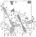
図に、第1のかご12と、このかごの下側に配された第2のかご14とを備えたエレベータ設備10を概略的に示す。これらのかごはシャフト16内を互いに独立に昇降させることができる。第1のかご12は単一のケーブルストランド18によってカウンタウェイト20に連結され、ケーブルストランド18はトラクションシーブ22及び方向転換ローラ24に巻き掛けられている。トラクションシーブ22及び方向転換ローラ24は、シャフト16の上端に位置するシャフト領域内又は機械スペース26内に保持される。トラクションシーブ22が駆動モータ28によって駆動される結果、第1のかごはシャフト16内を昇降することができる。ケーブルストランド18が複数の個別ケーブルを含むようにしてもよい。
FIG. 1 schematically shows an
第2のかご14は2つのケーブルストランド30,31によって別のカウンタウェイト33に連結されていて、カウンタウェイト33は、第1のかご12のカウンタウェイト20の横方向に隣接して配される。第2のかご14の2つのケーブルストランド30,31はそれぞれ、複数の個別ケーブルを含んでいてよい。これらのケーブルは、かご14の互いに対向する側面に固定されるため、第1のかご12の側方外側を走行する。これにより、後者がケーブルストランド30,31によって妨げられることはない。第2のかご14から出発して、ケーブルストランド第1区間30a,31aはそれぞれ垂直方向上方に延びて、上端のシャフト領域又は機械スペース26内にそれぞれ配された第1の方向転換ローラ35,36にまで達し、同所でケーブルストランド第2区間30b,31bにそれぞれ接続される。ケーブルストランド第2区間30b,31bは水平方向に延びてそれぞれ第2の方向転換ローラ38,39にまで達し、同所でケーブルストランドの各々は垂直方向に延びるケーブルストランド第3区間30c,31cにそれぞれ接続される。各々のケーブルストランド30,31は第1の方向転換ローラ35,36の箇所ならびに第2の方向転換ローラ38,39の箇所のいずれにあってもそれぞれ90°ずつ転向される。
The
ケーブルストランド第3区間30c,31cは垂直方向に延びてトラクションシーブ41にまで達する。共通のトラクションシーブ41は、駆動モータ44によって駆動され、かつ第1のトラクションシーブ部分42と後者に直に接する第2のトラクションシーブ部分43とを有する。トラクションシーブ部分42,43は、互いに剛的に、特には一体に連結されてよい。ケーブルストランド30は第1のトラクションシーブ部分42に巻き掛けられ、ケーブルストランド31は第2のトラクションシーブ部分43に巻き掛けられる。図1及び2に示す実施形態では、各トラクションシーブ部分42,43において、ケーブルストランド30,31はそれぞれ再度90°の転向に付される。このため、各ケーブルストランド第3区間30c,31cはそれぞれ、水平に並べられたケーブルストランド第4区間30d,31dにそれぞれ接続される。ケーブルストランド第4区間30d,31dはそれぞれ、第3の方向転換ローラ45,46のそれぞれ後方で、垂直方向下方に向かう、第2のかご14のカウンタウェイト33の箇所を終端とするケーブルストランド第5区間30e,31eにそれぞれ接続される。第3の方向転換ローラ45,46は互いに直に接している。これらの方向転換ローラは、単一部品の形をした共通の回動自在の方向転換ローラとして形成してもよい。
The cable strand
特に図2から明らかなように、第2のかご14の2つのケーブルストランド30,31は対称面48を中心にして互いに鏡像対称的に走行し、ケーブルストランド第1区間30a,31aはもとより、第3、第4及び第5のケーブルストランド区間30c,31c;30d,31d及び30e,31eも対称面と平行に走り、ケーブルストランド第2区間30b,31bはそれぞれ対称面に対して同じ角度で傾いている。
As is clear from FIG. 2 in particular, the two
また、図2から、第2のかご14のトラクションシーブ41の回転軸50は、結合線52と平行に走っていることも明らかである。結合線52は、ケーブルストランドの2区間30b,31bによって定義される水平面57とケーブルストランド第1区間30a,31aとの仮想上の交点54,55を互いに結ぶ。結合線52は、ケーブルストランド第4区間30d,31dに対して垂直に走行する。
It is also clear from FIG. 2 that the
2つのケーブルストランド30,31の各々は同じケーブル張力を有し、方向転換ローラ35,36,38,39,45,46及びトラクションシーブ41の箇所で生ずる方向変化の順序は2つのケーブルストランド30,31について同一である。ケーブルストランド30,31はいずれも、第2のかご14とカウンタウェイト33との間の領域で1回の反転変化を受けるだけである。なぜなら、ケーブルストランド30,31がそれぞれの第1の方向転換ローラ35,36の箇所で有する巻き掛け方向は、第2の方向転換ローラ38,39の箇所で有する巻き掛け方向とは逆である一方、第2の方向転換ローラ38,39の領域だけでなくトラクションシーブ41及び第3の方向転換ローラ45,46の領域においても巻き掛け方向はそれぞれ同じだからである。ケーブルストランド30の第1の方向転換ローラ35と第2の方向転換ローラ38との間の距離は、ケーブルストランド31の第1の方向転換ローラ36と第2の方向転換ローラ39との間の距離と同じである。同じことは第2の方向転換ローラ38,39のそれぞれとトラクションシーブ41との間の距離にもそのまま当てはまり、また、トラクションシーブ41と第3の方向転換ローラ45,46のそれぞれとの間の距離にも当てはまる。第2のかご14に対する2つのケーブルストランド30,31の各ケーブル締結点59,60と第1の方向転換ローラ35,36のそれぞれとの間の距離は同じであり、更に加えて、第3の方向転換ローラ45,46のそれぞれとカウンタウェイト33に対する2つのケーブルストランド30,31の共通のケーブル締結点62との間の距離も同じである。
Each of the two
図3に、第2の実施形態のケーブル案内装置を備えた、本発明によるエレベータ設備の概略平面図を示す。エレベータ設備は、図1,2に示したエレベータ設備10と概ね同じである。従って、図1,2の場合と同じ参照符号が図3の同一の部品に使用されている。繰り返しを避けるため、この点については上述の説明を参照されたい。
FIG. 3 shows a schematic plan view of an elevator installation according to the present invention provided with the cable guide device of the second embodiment. The elevator installation is substantially the same as the
図3に表された実施形態において、ケーブルストランド18は第1のかご12から出発して先ず方向転換ローラ24に巻き掛けられ、90°転向されて水平なケーブルストランド区間を経た後、トラクションシーブ22に達する。ケーブルストランド18は後者つまりトラクションシーブから直接カウンタウェイト20に向かって垂直方向に延びている。
In the embodiment represented in FIG. 3, the
図3に示した実施形態の場合にも、図1,2に表された実施形態と同様に、第2のかご14は2つのケーブルストランド30,31によって、第1のかご12のカウンタウェイト20の側方に隣接した配置されたカウンタウェイト33に連結されている。2つのケーブルストランド30,31はかご14の互いに対向する反対側の側面に固定され、第1のかご12の側方外側を走り、後者つまり第1のかごの脇を通過する。ケーブルストランド第1区間30a,31aはそれぞれ第2のかご14から垂直方向上方に延びて、上端のシャフト領域、又は機械スペース26内にそれぞれ配置された第1の方向転換ローラ35,36にまで達し、同所でケーブルストランド第2区間30b,31bにそれぞれ接続される。図1,2に表された第1実施形態とは異なって、ケーブルストランド第2区間30b,31bは、第2のかご14のカウンタウェイト33に面するかご14の側面の方向に延びている。区間は水平に延びてそれぞれ第2の方向転換ローラ38,39にまで達し、同所でそれぞれ垂直方向上方に延びるケーブルストランド第3区間30c,31cにそれぞれ接続される。ケーブルストランド30,31の各々はそれぞれ第1の方向転換ローラ35,36とそれぞれ第2の方向転換ローラ38,39の双方の箇所で90°ずつ転向される。
In the case of the embodiment shown in FIG. 3 as well, as in the embodiment shown in FIGS. 1 and 2, the
ケーブルストランド第3区間30c,31cは垂直方向に延びて、共通のトラクションシーブ41にまで達する。このトラクションシーブ41は、第2のかご14のケーブルストランド30,31がそれぞれ巻き掛けられる、互いに直接隣接した2つのトラクションシーブ部分42,43を有する共通である。ケーブルストランド30,31はそれぞれのトラクションシーブ部分42,43で180°の転向に付される。これにより、図3に表された実施形態において、それぞれのケーブルストランド第3区間30c,31cは、トラクションシーブ41から直接カウンタウェイト33に向かって延びる垂直方向に並べられたケーブルストランド第4区間30f,31fにそれぞれ接続されることとなる。
The cable strand
図1,2に表された第1の実施形態ならびに図3に表された第2の実施形態のいずれの場合にも、第2のかご14の2つのケーブルストランド30,31はエレベータ設備10の運転中ほぼ同じケーブル荷重を受け、そのためにまた、ほぼ同じ損耗を有する。これにより、2つのケーブルストランド30,31はケーブルの交換が行われなければならないほぼ同時点に最大許容損耗度に達することになる。ケーブルストランド30,31の伸び・滑り挙動もほぼ同じである。ケーブルストランド30,31の交換を同時に行うことができると共に、ケーブルストランド30,31のいずれをも最適に使用し切ることができる。結果として、エレベータ設備10の運転コストを比較的低く抑えることができる。
In both cases of the first embodiment shown in FIGS. 1 and 2 and the second embodiment shown in FIG. 3, the two
Claims (18)
第1のかご(12)の下側に第2のかご(14)が配され、
各々のかご(12,14)に、トラクションシーブ(22,41)を備えた駆動部(28,44)と、少なくとも1つのケーブルストランド(18;30,31)であって、前記トラクションシーブ(22,41)に巻き掛けられて前記かご(12;14)をカウンタウェイト(20;33)に連結するものとが関連付けられており、かつ
前記第2のかご(14)が、懸架比1:1で保持されると共に、該第2のかご(14)の前記トラクションシーブ(41)に巻き掛けられた、前記第2のかご(14)の異なる側面に関連付けられた2つのケーブルストランド(30,31)によって該かごのカウンタウェイト(33)に連結されるものにおいて、
前記第2のかご(14)に関連付けられた前記トラクションシーブ(41)が、2つのトラクションシーブ部分(42,43)を有し、該トラクションシーブ部分の各々に前記第2のかご(14)の前記2つのケーブルストランドの1つが巻き掛けられると共に、前記トラクションシーブ部分(42,43)の間の距離が、前記第2のかご(14)の領域における前記2つのケーブルストランド(30,31)の間の距離よりも小さいこと、及び、
本エレベータ設備(10)が、前記第2のかご(14)の前記2つのケーブルストランド(30,31)を等しい荷重に付するケーブル案内装置を有すること、及び、
上記ケーブル案内装置が方向転換ローラ(35,36,38,39,45,46)を含み、かつ
上記第2のかご(14)の上記2つのケーブルストランド(30,31)が、互いに対応する方向転換ローラ(35,36;38,39;45,46)及び上記第2のかご(14)の上記トラクションシーブ(41)にて、それぞれ同じ角度だけ転向されること、
を特徴とするエレベータ設備。An elevator installation with a plurality of cars in the shaft,
A second car (14) is arranged below the first car (12),
Each car (12, 14) includes a drive unit (28, 44) having a traction sheave (22, 41) and at least one cable strand (18; 30, 31), the traction sheave (22 , 41) is associated with the car (12; 14) connected to the counterweight (20; 33), and the second car (14) has a suspension ratio of 1: 1. And two cable strands (30, 31) associated with different sides of the second car (14) wound around the traction sheave (41) of the second car (14). ) Connected to the counterweight (33) of the car,
The traction sheave (41) associated with the second car (14) has two traction sheave portions (42, 43), each of the traction sheave portions of the second car (14). One of the two cable strands is wound and the distance between the traction sheave portions (42, 43) is such that the two cable strands (30, 31) in the region of the second car (14). Less than the distance between, and
The elevator installation (10) has a cable guide device for subjecting the two cable strands (30, 31) of the second car (14) to equal loads; and
The cable guiding device includes direction changing rollers (35, 36, 38, 39, 45, 46); and
The two cable strands (30, 31) of the second car (14) are connected to the corresponding direction changing rollers (35, 36; 38, 39; 45, 46) and the second car (14). Turning at the same angle in the traction sheave (41),
Elevator equipment characterized by
上記第2のかご(14)の上記2つのケーブルストランド(30,31)が、同じ数の方向転換ローラ(35,38,45;36,39,46)及び上記第2のかご(14)の上記トラクションシーブ(41)に巻き掛けられること、
を特徴とするもの。In the elevator installation according to claim 1 or 2 ,
The two cable strands of the upper Symbol second car (14) (30, 31) is, deflecting rollers of the same number (35,38,45; 36,39,46) and the second car (14) To be wound around the traction sheave (41) of
It is characterized by.
2つの隣接する方向転換ローラ(35,38,45;36,39,46)の間の距離及び上記第2のかご(14)の上記トラクションシーブ(41)と該トラクションシーブに隣接する方向転換ローラ(38,45;39,46)との間の距離が、上記第2のかご(14)の双方のケーブルストランド(30,31)につき同じであること、
を特徴とするもの。In the elevator installation according to claim 1, 2 or 3 ,
Two adjacent deflecting rollers (35,38,45; 36,39,46) distance and deflecting rollers the traction sheave (41) adjacent to the traction sheave of the second car (14) between the The distance between (38, 45; 39, 46) is the same for both cable strands (30, 31) of the second car (14);
It is characterized by.
上記各方向転換ローラ(35,38,45;36,39,46)及び上記トラクションシーブ(41)にて生ずる方向変化の順序が、上記第2のかご(14)の上記2つのケーブルストランド(30,31)につき同じであること、
を特徴とするもの。In the elevator installation of any one of Claim 1 to 4 ,
Upper Symbol Each deflecting rollers (35,38,45; 36,39,46) and the order of the direction change that occurs at the traction sheave (41) is the second of the two cable strands of the basket (14) ( The same for 30, 31)
It is characterized by.
を特徴とするもの。The elevator installation according to any one of claims 1 to 5, wherein the two cable strands (30, 31) of the second car (14) are mirror-image-symmetric with respect to a plane of symmetry (48). Traveling to,
It is characterized by.
上記第2のかご(14)の上記2つのケーブルストランド(30,31)がそれぞれ、上記第2のかご(14)から出発して第1の方向転換ローラ(35;36)まで延びるケーブルストランド第1区間(30a;31a)と、前記第1区間に接続されるケーブルストランド第2区間(30b;31b)とを有し、かつ
前記ケーブルストランド第2区間(30b;31b)が前記ケーブルストランド第1区間(30a;31a)に対して垂直に並べられること、
を特徴とするもの。In the elevator installation of any one of Claim 1 to 6,
The two cable strands (30, 31) of the second car (14) each extend from the second car (14) to the first turning roller (35; 36). 1 section (30a; 31a) and a cable strand second section (30b; 31b) connected to the first section, and the cable strand second section (30b; 31b) is the cable strand first Being arranged perpendicular to the section (30a; 31a),
It is characterized by.
上記ケーブルストランド第2区間(30b,31b)がそれぞれ第2の方向転換ローラ(38;39)まで延び、該方向転換ローラにて上記第2区間がケーブルストランド第3区間(30c;31c)に接続され、かつ
前記ケーブルストランド第3区間(30c;31c)が互いに平行に並べられること、
を特徴とするもの。In the elevator installation according to claim 7 or 8,
The cable strand second section (30b, 31b) extends to the second direction change roller (38; 39), and the direction change roller connects the second section to the cable strand third section (30c; 31c). The cable strand third sections (30c; 31c) are arranged in parallel to each other;
It is characterized by.
上記ケーブルストランド第3区間(30c;31c)が、第3の方向転換ローラ又は上記第2のかご(14)の上記トラクションシーブ(41)まで延び、該方向転換ローラ又は該トラクションシーブ(41)にて上記第3区間がケーブルストランド第4区間(30d;31d)に接続され、かつ
前記ケーブルストランド第4区間(30d;31d)が互いに平行に並べられること、
を特徴とするもの。In the elevator installation according to claim 9 or 10,
The cable strand third section (30c; 31c) extends to the traction sheave (41) of the third direction changing roller or the second car (14), and is connected to the direction changing roller or the traction sheave (41). The third section is connected to the cable strand fourth section (30d; 31d), and the cable strand fourth section (30d; 31d) is arranged in parallel to each other;
It is characterized by.
上記ケーブルストランド第4区間(30d;31d)が、上記第2のかご(14)の上記トラクションシーブ(41)から第3の方向転換ローラ(45;46)まで延び、該方向転換ローラにて上記ケーブルストランド第4区間がケーブルストランド第5区間(30e;31e)に接続され、かつ
前記ケーブルストランド第5区間(30e;31e)が互いに平行に並べられること、
を特徴とするもの。In the elevator installation according to claim 11 or 13,
The fourth section (30d; 31d) of the cable strand extends from the traction sheave (41) of the second car (14) to the third direction changing roller (45; 46). A cable strand fourth section is connected to a cable strand fifth section (30e; 31e), and the cable strand fifth sections (30e; 31e) are arranged in parallel to each other;
It is characterized by.
を特徴とするもの。In the elevator installation according to claim 14, the cable strand fifth section (30e; 31e) is arranged vertically,
It is characterized by.
上記第2のかご(14)に関連付けられた上記トラクションシーブ(41)の回転軸(50)が水平結合線(52)と平行に並べられ、かつ
前記水平結合線が、上記第2のかご(14)に結合された、上記2つのケーブルストランド(30,31)の上記ケーブルストランド第1区間(30a;31a)と水平面(57)との交点(54,55)を結ぶこと、
を特徴とするもの。The elevator installation according to any one of claims 1 to 16,
The rotation axis (50) of the traction sheave (41) associated with the second car (14) is arranged in parallel with the horizontal coupling line (52), and the horizontal coupling line is connected to the second car ( 14) connecting the intersections (54, 55) between the cable strand first section (30a; 31a) and the horizontal plane (57) of the two cable strands (30, 31),
It is characterized by.
Applications Claiming Priority (3)
| Application Number | Priority Date | Filing Date | Title |
|---|---|---|---|
| EP05005444A EP1700809B1 (en) | 2005-03-12 | 2005-03-12 | Elevator system |
| EP05005444.4 | 2005-03-12 | ||
| PCT/EP2005/011545 WO2006097140A1 (en) | 2005-03-12 | 2005-10-28 | Elevator system |
Publications (2)
| Publication Number | Publication Date |
|---|---|
| JP2008532881A JP2008532881A (en) | 2008-08-21 |
| JP5028403B2 true JP5028403B2 (en) | 2012-09-19 |
Family
ID=34982264
Family Applications (1)
| Application Number | Title | Priority Date | Filing Date |
|---|---|---|---|
| JP2008500056A Expired - Fee Related JP5028403B2 (en) | 2005-03-12 | 2005-10-28 | Elevator equipment |
Country Status (13)
| Country | Link |
|---|---|
| US (1) | US7753174B2 (en) |
| EP (1) | EP1700809B1 (en) |
| JP (1) | JP5028403B2 (en) |
| KR (1) | KR100971519B1 (en) |
| CN (1) | CN101142132B (en) |
| AT (1) | ATE465967T1 (en) |
| BR (1) | BRPI0520121A2 (en) |
| DE (1) | DE502005009483D1 (en) |
| ES (1) | ES2341550T3 (en) |
| MX (1) | MX2007011134A (en) |
| RU (1) | RU2412894C2 (en) |
| TW (1) | TWI295272B (en) |
| WO (1) | WO2006097140A1 (en) |
Families Citing this family (14)
| Publication number | Priority date | Publication date | Assignee | Title |
|---|---|---|---|---|
| NZ562338A (en) | 2006-10-31 | 2009-07-31 | Inventio Ag | Lift with two lift cages disposed one above the other in a lift shaft |
| EP1918238B1 (en) * | 2006-10-31 | 2011-03-09 | Inventio AG | Elevator with two superimposed cars in one shaft |
| US7661513B2 (en) | 2006-12-14 | 2010-02-16 | Inventio Ag | Dual-car elevator system with common counterweight |
| MY149179A (en) * | 2006-12-14 | 2013-07-31 | Inventio Ag | Lift system |
| US7857103B2 (en) | 2006-12-14 | 2010-12-28 | Inventio Ag | Elevator system |
| EP1935826B1 (en) * | 2006-12-14 | 2011-05-11 | Inventio AG | Lift system |
| ZA200710597B (en) | 2006-12-21 | 2008-11-26 | Inventio Ag | Method of preventing collision of two lift cages movable in the same shaft of a lift installation and corresponding lift installation |
| FI20070562L (en) * | 2007-07-20 | 2009-01-21 | Kone Corp | Elevator |
| US8448323B2 (en) * | 2010-10-15 | 2013-05-28 | Kone Corporation | Method for modernizing an elevator |
| CN102398822A (en) * | 2011-09-30 | 2012-04-04 | 快意电梯有限公司 | Elevator arrangement structure |
| EP2712834A1 (en) | 2012-09-27 | 2014-04-02 | Inventio AG | Drive and cable guidance configuration |
| CN109179168A (en) * | 2018-11-01 | 2019-01-11 | 浙江华夏电梯有限公司 | A kind of three cabin elevator of double traction machines |
| DE102019200375A1 (en) | 2019-01-15 | 2020-07-16 | Thyssenkrupp Ag | Elevator system with a first suspension and a second suspension on a car |
| CN112279043A (en) * | 2020-09-21 | 2021-01-29 | 浙江鲸叹科技有限公司 | Double-tractor elevator |
Family Cites Families (39)
| Publication number | Priority date | Publication date | Assignee | Title |
|---|---|---|---|---|
| USRE18095E (en) | 1931-06-09 | Dtjal elevator system and control | ||
| US18095A (en) * | 1857-09-01 | Surf and life boat | ||
| US1164115A (en) * | 1909-01-21 | 1915-12-14 | Charles O Pearson | Traction-elevator. |
| US1763198A (en) * | 1926-12-31 | 1930-06-10 | Westinghouse Electric & Mfg Co | Dual elevator system and control |
| US1896776A (en) * | 1928-02-17 | 1933-02-07 | Westinghouse Electric & Mfg Co | Multiple elevator system |
| US1782671A (en) * | 1929-05-13 | 1930-11-25 | Jr William P Allred | Storage and parking garage |
| US1805227A (en) * | 1929-05-27 | 1931-05-12 | Westinghouse Electric & Mfg Co | Multiple-car elevator |
| US1911834A (en) * | 1931-02-26 | 1933-05-30 | Otis Elevator Co | Elevator system |
| US1837643A (en) * | 1931-03-28 | 1931-12-22 | Otis Elevator Co | Elevator system |
| DE884562C (en) | 1942-02-27 | 1953-08-24 | Foerderanlagen Ernst Heckel M | Device for automatic compensation of changes in rope length when carrying multiple ropes |
| DE2209455A1 (en) | 1972-02-29 | 1973-09-06 | Rudolf Dr Ing Vogel | DEVICE FOR TRANSPORTING LOADS, E.G. THE CAB OF AN ELEVATOR |
| FI84051C (en) * | 1988-03-09 | 1991-10-10 | Kone Oy | LINUPPHAENGNING FOER EN HISS. |
| DE9201374U1 (en) * | 1992-02-05 | 1992-04-02 | C. Haushahn Gmbh & Co, 7000 Stuttgart, De | |
| FI92182C (en) | 1992-07-07 | 1994-10-10 | Kone Oy | Traction sheave elevator |
| US5419414A (en) * | 1993-11-18 | 1995-05-30 | Sakita; Masami | Elevator system with multiple cars in the same hoistway |
| JPH07223785A (en) * | 1994-02-04 | 1995-08-22 | Otis Elevator Co | Hoisting type elevator |
| US5490577A (en) * | 1994-06-22 | 1996-02-13 | Otis Elevator Company | Flexible elevator hitch |
| DE19835960A1 (en) | 1998-08-08 | 2000-02-17 | Klaus Schulz Ind Service Gmbh | Method for tensioning ropes and cables of hoist has hydraulic rams on each cable to set a common tension |
| JP4131764B2 (en) * | 1998-09-01 | 2008-08-13 | 東芝エレベータ株式会社 | Elevator equipment |
| JP4442941B2 (en) * | 1998-09-09 | 2010-03-31 | 東芝エレベータ株式会社 | Elevator equipment |
| EP1006071A1 (en) | 1998-12-02 | 2000-06-07 | Inventio Ag | Elevator with two drives |
| KR100319936B1 (en) * | 1999-03-04 | 2002-01-09 | 장병우 | Vibration reducing device for elevator car |
| US6223862B1 (en) * | 1999-06-17 | 2001-05-01 | Michael Barnes | Elevator cable tensioning device and method |
| DE19963286B4 (en) | 1999-12-27 | 2005-06-23 | Aufzugfabrik Wilhelm Nunn Gmbh & Co. | elevator |
| EP1123891A3 (en) | 2000-02-09 | 2002-05-02 | Otis Elevator Company | Dead end hitch for elevator rope |
| US6341669B1 (en) | 2000-06-21 | 2002-01-29 | Otis Elevator Company | Pivoting termination for elevator rope |
| DE60043517D1 (en) * | 2000-10-10 | 2010-01-21 | Mitsubishi Electric Corp | LIFT DEVICE |
| CN1177748C (en) * | 2000-10-31 | 2004-12-01 | 三菱电机株式会社 | Power supply for elevator with multiple compartments |
| WO2002038481A1 (en) | 2000-11-08 | 2002-05-16 | Mitsubishi Denki Kabushiki Kaisha | Main rope elongation compensating device for elevator |
| EP1357073A4 (en) | 2000-12-07 | 2006-05-31 | Mitsubishi Electric Corp | Elevator main rope elongation sensor |
| KR100381607B1 (en) | 2001-03-02 | 2003-04-30 | 최정두 | Rope tension-equalizer of elevator |
| DE10145744A1 (en) | 2001-09-17 | 2003-04-10 | Johannes Rinio | Hoist or lift for goods or people has fixed guides on track, suspension cable line running over deflector rollers, compensating weight, drive mechanism, and tensioning appliance |
| ATE305894T1 (en) | 2001-10-15 | 2005-10-15 | Thyssenkrupp Elevator Ag | CABLE ELEVATOR SYSTEM WITH TWO CARS WITH COMMON AND SEPARATE TRAVEL SECTIONS |
| EP1834919B1 (en) | 2001-11-23 | 2011-06-15 | Inventio AG | Lift system |
| JP4110138B2 (en) | 2002-06-10 | 2008-07-02 | 三菱電機株式会社 | Elevator equipment |
| CN100344521C (en) * | 2002-11-18 | 2007-10-24 | 三菱电机株式会社 | Elevator device |
| EP1586525B1 (en) * | 2003-01-23 | 2013-01-02 | Mitsubishi Denki Kabushiki Kaisha | Elevator equipment |
| US7661513B2 (en) * | 2006-12-14 | 2010-02-16 | Inventio Ag | Dual-car elevator system with common counterweight |
| US7857103B2 (en) * | 2006-12-14 | 2010-12-28 | Inventio Ag | Elevator system |
-
2005
- 2005-03-12 AT AT05005444T patent/ATE465967T1/en active
- 2005-03-12 DE DE502005009483T patent/DE502005009483D1/en active Active
- 2005-03-12 EP EP05005444A patent/EP1700809B1/en not_active Revoked
- 2005-03-12 ES ES05005444T patent/ES2341550T3/en active Active
- 2005-10-28 JP JP2008500056A patent/JP5028403B2/en not_active Expired - Fee Related
- 2005-10-28 CN CN2005800490565A patent/CN101142132B/en not_active Expired - Fee Related
- 2005-10-28 WO PCT/EP2005/011545 patent/WO2006097140A1/en not_active Application Discontinuation
- 2005-10-28 RU RU2007137629/11A patent/RU2412894C2/en not_active IP Right Cessation
- 2005-10-28 MX MX2007011134A patent/MX2007011134A/en active IP Right Grant
- 2005-10-28 KR KR1020077020872A patent/KR100971519B1/en active IP Right Grant
- 2005-10-28 BR BRPI0520121-7A patent/BRPI0520121A2/en not_active IP Right Cessation
-
2006
- 2006-03-09 TW TW095107869A patent/TWI295272B/en not_active IP Right Cessation
-
2007
- 2007-09-07 US US11/899,989 patent/US7753174B2/en active Active
Also Published As
| Publication number | Publication date |
|---|---|
| ATE465967T1 (en) | 2010-05-15 |
| DE502005009483D1 (en) | 2010-06-10 |
| CN101142132B (en) | 2011-04-13 |
| EP1700809A1 (en) | 2006-09-13 |
| JP2008532881A (en) | 2008-08-21 |
| US7753174B2 (en) | 2010-07-13 |
| US20080060881A1 (en) | 2008-03-13 |
| BRPI0520121A2 (en) | 2009-04-22 |
| WO2006097140A1 (en) | 2006-09-21 |
| KR20070106769A (en) | 2007-11-05 |
| EP1700809B1 (en) | 2010-04-28 |
| RU2007137629A (en) | 2009-04-20 |
| CN101142132A (en) | 2008-03-12 |
| TWI295272B (en) | 2008-04-01 |
| MX2007011134A (en) | 2007-10-23 |
| RU2412894C2 (en) | 2011-02-27 |
| ES2341550T3 (en) | 2010-06-22 |
| KR100971519B1 (en) | 2010-07-21 |
| TW200702280A (en) | 2007-01-16 |
Similar Documents
| Publication | Publication Date | Title |
|---|---|---|
| JP5028403B2 (en) | Elevator equipment | |
| US7918319B2 (en) | Elevator apparatus | |
| JP2004520245A (en) | Gear operated cable operated elevator | |
| TWI386359B (en) | Lift with two lift cages, which are disposed one above the other, in a shaft | |
| WO2002022486A1 (en) | Elevator device | |
| JP5800916B2 (en) | Elevator equipment with 4: 1 roping | |
| KR100956208B1 (en) | Elevator device | |
| JP5460715B2 (en) | Elevator equipment | |
| KR101016822B1 (en) | Elevator device | |
| JP4597049B2 (en) | Elevator configuration without machine room with small overhead | |
| KR101887613B1 (en) | Super Size Rope Type Elevator for Extremely Heavy Load Drived by Plural Traction Machine | |
| KR20050002816A (en) | Elevator equipment | |
| JP4675548B2 (en) | Elevator equipment | |
| KR101011280B1 (en) | Elevator device | |
| JP4750104B2 (en) | Elevator equipment | |
| EP1717185B1 (en) | Elevator | |
| JP4841211B2 (en) | Elevator car door drive | |
| KR100619203B1 (en) | Machine-roomless elevator system with an elevator machine mounted on an elevator car | |
| JP2011051736A (en) | Elevator device | |
| KR100911079B1 (en) | Elevator device | |
| JP4561290B2 (en) | Elevator equipment | |
| JP4170290B2 (en) | Elevator equipment | |
| KR20060036925A (en) | Low overhead machine roomless elevator configuration | |
| KR19990009932U (en) | Sheave of hoist for elevator |
Legal Events
| Date | Code | Title | Description |
|---|---|---|---|
| A977 | Report on retrieval |
Free format text: JAPANESE INTERMEDIATE CODE: A971007 Effective date: 20110309 |
|
| A131 | Notification of reasons for refusal |
Free format text: JAPANESE INTERMEDIATE CODE: A131 Effective date: 20110315 |
|
| A601 | Written request for extension of time |
Free format text: JAPANESE INTERMEDIATE CODE: A601 Effective date: 20110613 |
|
| A602 | Written permission of extension of time |
Free format text: JAPANESE INTERMEDIATE CODE: A602 Effective date: 20110620 |
|
| A521 | Request for written amendment filed |
Free format text: JAPANESE INTERMEDIATE CODE: A523 Effective date: 20110713 |
|
| A02 | Decision of refusal |
Free format text: JAPANESE INTERMEDIATE CODE: A02 Effective date: 20120117 |
|
| A521 | Request for written amendment filed |
Free format text: JAPANESE INTERMEDIATE CODE: A523 Effective date: 20120516 |
|
| A911 | Transfer to examiner for re-examination before appeal (zenchi) |
Free format text: JAPANESE INTERMEDIATE CODE: A911 Effective date: 20120523 |
|
| TRDD | Decision of grant or rejection written | ||
| A01 | Written decision to grant a patent or to grant a registration (utility model) |
Free format text: JAPANESE INTERMEDIATE CODE: A01 Effective date: 20120619 |
|
| A01 | Written decision to grant a patent or to grant a registration (utility model) |
Free format text: JAPANESE INTERMEDIATE CODE: A01 |
|
| A61 | First payment of annual fees (during grant procedure) |
Free format text: JAPANESE INTERMEDIATE CODE: A61 Effective date: 20120625 |
|
| FPAY | Renewal fee payment (event date is renewal date of database) |
Free format text: PAYMENT UNTIL: 20150629 Year of fee payment: 3 |
|
| R150 | Certificate of patent or registration of utility model |
Free format text: JAPANESE INTERMEDIATE CODE: R150 |
|
| FPAY | Renewal fee payment (event date is renewal date of database) |
Free format text: PAYMENT UNTIL: 20150629 Year of fee payment: 3 |
|
| S531 | Written request for registration of change of domicile |
Free format text: JAPANESE INTERMEDIATE CODE: R313531 |
|
| FPAY | Renewal fee payment (event date is renewal date of database) |
Free format text: PAYMENT UNTIL: 20150629 Year of fee payment: 3 |
|
| R350 | Written notification of registration of transfer |
Free format text: JAPANESE INTERMEDIATE CODE: R350 |
|
| R250 | Receipt of annual fees |
Free format text: JAPANESE INTERMEDIATE CODE: R250 |
|
| R250 | Receipt of annual fees |
Free format text: JAPANESE INTERMEDIATE CODE: R250 |
|
| R250 | Receipt of annual fees |
Free format text: JAPANESE INTERMEDIATE CODE: R250 |
|
| LAPS | Cancellation because of no payment of annual fees |