EP1586525B1 - Elevator equipment - Google Patents
Elevator equipment Download PDFInfo
- Publication number
- EP1586525B1 EP1586525B1 EP03701840A EP03701840A EP1586525B1 EP 1586525 B1 EP1586525 B1 EP 1586525B1 EP 03701840 A EP03701840 A EP 03701840A EP 03701840 A EP03701840 A EP 03701840A EP 1586525 B1 EP1586525 B1 EP 1586525B1
- Authority
- EP
- European Patent Office
- Prior art keywords
- hoist
- way
- cage
- turning
- sheave
- Prior art date
- Legal status (The legal status is an assumption and is not a legal conclusion. Google has not performed a legal analysis and makes no representation as to the accuracy of the status listed.)
- Expired - Lifetime
Links
- 238000004804 winding Methods 0.000 claims description 32
- 229910000831 Steel Inorganic materials 0.000 claims description 5
- 230000005484 gravity Effects 0.000 claims description 5
- 239000010959 steel Substances 0.000 claims description 5
- 230000003247 decreasing effect Effects 0.000 description 4
- 238000005299 abrasion Methods 0.000 description 3
- 238000012423 maintenance Methods 0.000 description 3
- 230000002035 prolonged effect Effects 0.000 description 3
- 230000000994 depressogenic effect Effects 0.000 description 2
- 238000000034 method Methods 0.000 description 2
- 208000019901 Anxiety disease Diseases 0.000 description 1
- 230000036506 anxiety Effects 0.000 description 1
- 238000007689 inspection Methods 0.000 description 1
Images


Classifications
-
- B—PERFORMING OPERATIONS; TRANSPORTING
- B66—HOISTING; LIFTING; HAULING
- B66B—ELEVATORS; ESCALATORS OR MOVING WALKWAYS
- B66B7/00—Other common features of elevators
- B66B7/06—Arrangements of ropes or cables
-
- B—PERFORMING OPERATIONS; TRANSPORTING
- B66—HOISTING; LIFTING; HAULING
- B66B—ELEVATORS; ESCALATORS OR MOVING WALKWAYS
- B66B11/00—Main component parts of lifts in, or associated with, buildings or other structures
- B66B11/0065—Roping
- B66B11/008—Roping with hoisting rope or cable operated by frictional engagement with a winding drum or sheave
Description
- The present invention relates to an art of layout in an elevator without a machine room.
-
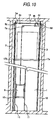
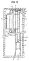
Fig. 11 is a plan view of a hoist-way in a conventional elevator without a machine room as disclosed inJP-A-2000-255933 Pages Fig. 12 is a vertical sectional view of the hoist-way. The drawings show an elevator device having 2:1 roping which includes acage 3 suspended by ahoisting rope 15 which is wound around asheave 4a of awinding machine 4 at the top of the hoist-way, and abalance weight 9 which moves up and down in proportion to the cage. In this example, thewinding machine 4, thesheave 4a and afirst turning pulley 5 are arranged in parallel to a ceiling face of the hoist-way, and the hoisting rope is turned to a vertical direction by means of asecond turningpulley 6 and then, wound around two suspendingpulleys 18 which are pivotally attached to a lower part of the cage thereby to suspend thecage 3. On the other hand, thebalance weight 9 is suspended by turning thehoisting rope 15 from thesheave 4a to a vertical direction by means of a turningpulley 7 at a side of the balance weight, and by winding thehoisting rope 15 around a suspendingpulley 19 which is pivotally attached to theweight balance 9. - The reason why the winding machine, the sheave and the first turning pulley are arranged in parallel to the ceiling face of the hoist-way is to make a gap at the top of the cage as small as possible. However, due to a fact that the winding machine is provided on the ceiling face of the hoist-way, on occasion of maintenance and inspection, a worker is forced to climb on a roof of a cage room to do the work in an upwardly directed state, which will incur a heavy working load. As alternative means, there has been a method of providing a device for opening or closing the winding machine downwardly together with its mounting frame for the maintenance work, but this method has had a problem of incurring a high cost. Moreover, in the conventional elevator without a machine room, in case of 1:1 roping, it has been difficult to contain the winding machine and the turning pulleys in a narrow gap at the top. Therefore, an elevator having 2:1 roping in which the winding machine and the turning pulleys can be easily disposed on a side face of the cage and the small winding machine may be sufficient has been generally employed. Recently, it has become possible to make the winding machine, the sheave and the turning pulleys smaller in diameter, because a rope having excellent flexibility and a steel rope having a small diameter and high strength has been developed and produced. In this case, however, there has been such anxiety that rotation numbers of both the winding machine and the turning pulleys may be increased and noises may occur, when they are simply combined with the elevator having 2:1 roping.
-
WO 02-22486 Claims EP 1 057 771 A2 - This invention has been made in order to solve the above described problems, and an object of the invention is to obtain an elevator having 1:1 roping in which a hoist-way is decreased to the smallest in size, while a maintenance space for a winding machine can be secured.
- As means for solving the above described problems, an elevator device comprises the features of
Claim 1. - Moreover, in the above described structure, the first turning pulley and the second turning pulley are in combination preferably having different diameters from each other.
- Further, another solution of the problem is the elevator device having the features of
Claim 3. - Still further, preferably, in the above described structure, the winding machine, sheave and turning pulleys are made smaller in size, and a plurality of the turning pulleys which are not in parallel to the ceiling of the hoist-way are arranged in a gap between the cage and the wall of the hoist-way.
- Still further, preferably, in each of the above described elevators, a rope having excellent flexibility or a steel rope having a small diameter and high strength is applied to the hoisting rope, and the winding machine, sheave and turning pulleys are made smaller in size.
-
-
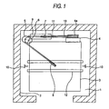
Fig. 1 is a plan view showing a top part of a hoist-way inEmbodiment 1 according to this invention. -
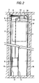
Fig. 2 is a vertical sectional view of the hoist-way inFig. 1 . -
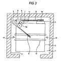
Fig. 3 is a plan view showing a top part of a hoist-way inEmbodiment 2 according to this invention. -
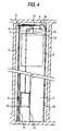
Fig. 4 is a vertical sectional view of both the hoist-ways inFigs. 3 and5 . -
Fig. 5 is a plan view showing a top part of a hoist-way inEmbodiment 3 according to this invention. -
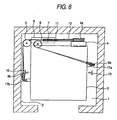
Fig. 6 is a plan view showing a top part of a hoist-way inEmbodiment 4 according to this invention. -
Fig. 7 is a vertical sectional view of both the hoist-ways inFigs. 6 and8 . -
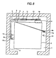
Fig. 8 is a plan view showing a top part of a hoist-way inEmbodiment 5 according to this invention. -
Fig. 9 is a plan view showing a top part of a hoist-way inEmbodiment 6 according to this invention. -
Fig. 10 is a vertical sectional view of the hoist-way inFig. 9 . -
Fig. 11 is a plan view showing a top part of a hoist-way in a conventional elevator without a machine room. -
Fig. 12 is a vertical sectional view of the hoist-way inFig. 11 . - Now, embodiments of the present invention will be described.
-
Fig. 1 is a plan view showing relation between a sheave of a winding machine and turning pulleys at the top of the hoist-way inEmbodiment 1 according to this invention, andFig. 2 is a vertical sectional view of the hoist-way. The drawings show an elevator device having 1:1 roping which includes acage 3 moving up and down along a pair ofguide rails 10 provided in the hoist-way, ahoisting rope 13 which is engaged at its one end with thecage 3 and engaged at the other end with abalance weight 9 moving up and down alongother guide rails 11, and awinding machine 4 having asheave 4a around which the hoisting rope is wound. The elevator device is constructed in such a manner that thewinding machine 4 is arranged close to a wall of the hoist-way in an upper part of the hoist-way, thesheave 4a is provided so as not to be in parallel to a ceiling face of the hoist-way, a plurality of theropes 13 are divided into more than two lines of afirst turning pulley 5 and asecond turning pulley 6 which are arranged in parallel to the ceiling face of the hoist-way to be deflected to a center of gravity of the cage, and the ropes are further turned to a vertical direction by means of a third turningpulley 8 and engaged with rope retaining parts of the cage thereby to suspend the cage. - Therefore, according to this layout, the 1:1 roping can be attained even in a narrow gap at the top of the hoist-way, and even though a number of the hoisting ropes are employed, a rope fleet angle, that is, an angle at which the ropes are likely to be detached from rope grooves in the sheave or the turning pulleys can be depressed to a small angle, because a plurality, more than two, of the first turning pulley and the second turning pulley are employed.
- In addition, because the rope fleet angle can be made small, deflected abrasion of the rope grooves can be restrained, and noises can be decreased, thus enabling effective lives of the ropes to be prolonged.
-
Fig. 3 is a plan view corresponding toFig. 1 , showingEmbodiment 2.Fig. 4 is a vertical sectional view of the hoist-way inFig. 3 .Embodiment 2 is the same as the above described structure, except that two turning pulleys, namely thesecond turning pulley 6 and a third turningpulley 6a are employed, while the first turningpulley 5 is single, in other words, the three turning pulleys in total from the first to the third are employed. Moreover, since the same members or equivalent members as in the foregoing embodiment are designated by the same reference numerals, further description will be omitted. - As the results, in addition to the advantages in the foregoing embodiment, because the two turning pulleys, namely the
second turning pulley 6 and the third turningpulley 6a are employed in combination, while thefirst turning pulley 5 is single, shafts and bearing beams of the turningpulleys pulley 5 and interference will not occur. Accordingly, such an advantage that the turning pulleys can be arranged more close to each other in a vertical direction, and the above described rope fleet angle can be made smaller can be obtained. -
Fig. 5 is a plan view corresponding toFig. 3 , showingEmbodiment 3, andFig. 4 is a vertical sectional view of the hoist-way inFig. 5 . InEmbodiment 2, the two turning pulleys, namely the second turningpulley 6 and the third turningpulley 6a are combined, while the first turningpulley 5 is single. However, in this embodiment, the diameter of the turningpulley 5 is made smaller so as to match a turning angle of therope 13 drawn out from thesheave 4a of the winding machine to the center of gravity of the cage in view of a layout, and a diameter of a single second turningpulley 6b is made larger instead of employing the two turningpulleys pulley 6b is selected so as to match the turning angles of thesheave 4a and the turningpulley 5, thereby to restrict angles of the ropes with respect to respective rope grooves in the third turningpulley 8 within an allowable range. Further description will be omitted, because arrangement of the other members is the same as inEmbodiment 2, and the same reference numerals designate the same members or equivalent members. - As the results, the optimum rope fleet angle can be obtained by making the diameters of the first turning pulley and the second turning pulley different from each other, and by selecting and combining the diameters of the turning pulleys so as to match differences between the turning angles of the rope. Moreover, in the same manner as in the foregoing embodiment, the shaft and bearing beam of the second turning
pulley 6b are located apart from thefirst turning pulley 5, and interference will not occur. Accordingly, such an advantage that the turning pulleys can be positioned more close to each other in a vertical direction, and the above described rope fleet angle can be made smaller can be attained. -
Fig. 6 is a plan view corresponding toFig. 1 , showingEmbodiment 4, andFig. 7 is a vertical sectional view of the hoist-way inFig. 6 . The drawings show an elevator device having the 1:1 roping which includes a cage, a hoisting rope which is engaged at its one end with the cage and engaged at the other end with a balance weight which moves up and down with respect to the cage, and a winding machine having a sheave around which the hoisting rope is wound. The elevator device is constructed in such a manner that the above describedwinding machine 4 is arranged close to the wall of the hoist-way in the upper part of the hoist-way, the above describedsheave 4a is provided so as not to be in parallel to the ceiling face of the hoist-way, a plurality of theropes 13 from thesheave 4a to the cage are divided to thefirst turning pulley 5 and the second turningpulley 6 which are arranged in parallel to the ceiling face of the hoist-way to be deflected, and the ropes are further turned to a vertical direction respectively by means of a third turningpulley 8a and afourth turning pulley 8b for the purpose of dropping down the ropes to two rope retaining parts at both sides of the cage, thereby to suspend the cage. - As the results, the 1:1 roping can be attained in a narrow gap at the top of the hoist-way, and a deflected load will not be exerted on the cage, because the cage is suspended at two points surrounding the center of gravity of the cage. Therefore, this elevator device can be applied to the elevator having a large capacity. Even though a number of the hoisting ropes are employed, the rope fleet angle can be made small because the ropes are divided to the first turning pulley and the second turning pulley. In addition, because the rope fleet angle can be made small, deflected abrasion of the rope grooves can be restrained, and noises can be decreased, thus enabling effective lives of the ropes to be prolonged.
-
Fig. 8 is a plan view corresponding toFig. 6 , showingEmbodiment 5, andFig. 7 is a vertical sectional view of the hoist-way inFig. 8 . The winding machine, sheave and turning pulleys are made smaller in size, and all of a plurality of the turning pulleys which are not in parallel to the ceiling of the hoist-way are arranged in a gap between the cage and the wall of the hoist-way. Further description will be omitted, because arrangement of the other members is the same as in the foregoing embodiments, and the same reference numerals designate the same members or equivalent members. - As the results, in addition to the advantages in the foregoing embodiments, due to the fact that the turning pulleys are arranged in the gap between the cage and the wall of the hoist-way, they are not overlapped on a plain of the cage and become free from restraint in the gap above the top of the cage. Accordingly, such an advantage that the turning pulleys can be contained in the narrow gap above the top of the cage can be obtained.
-
Fig. 9 is a plan view corresponding toFig. 8 , showingEmbodiment 6, andFig. 10 is a vertical sectional view of the hoist-way inFig. 9 . In this embodiment, a rope having excellent flexibility or a steel rope having a small diameter and high strength is applied to the hoisting rope, and the winding machine, sheave and turning pulleys are made smaller in size, in the above described elevators. Further description will be omitted, because arrangement of the other members is the same as in the foregoing embodiments. It is self-explanatory that such application of the steel rope having the small diameter and high strength, and downsizing of the winding machine, sheave and turning pulleys can be also applied toEmbodiments 1 to 4 in the same manner. - As the results, it is possible to further save space in each of the above described elevators without a machine room.
- This invention having the above described structure can attain such advantages as described below.
- The elevator device having 1:1 roping which includes a cage moving up and down along a pair of guide rails provided in a hoist-way, a hoisting rope which is engaged at its one end with the aforesaid cage and engaged at the other end with a balance weight moving up and down along other guide rails, and a winding machine having a sheave around which the aforesaid hoisting rope is wound is constructed in such a manner that the aforesaid winding machine is disposed close to a wall of the hoist-way in an upper part of the hoist-way, having the aforesaid sheave arranged not in parallel to a ceiling face of the hoist-way, a plurality of the ropes stretched from the aforesaid sheave to the aforesaid cage are divided into more than two lines of a first turning pulley and a second turning pulley which are arranged in parallel to the ceiling of the hoist-way thereby to be deflected to a center of gravity of the cage, and then, the ropes are turned to a vertical direction by means of a third turning pulley, whereby the ropes are engaged with rope retaining parts of the cage to suspend the cage.
- Therefore, according to the above described layout, the 1:1 roping can be attained even in the narrow gap at the top of the hoist-way, and even though a number of the hoisting ropes are employed, the rope fleet angle, that is, the angle at which the ropes are likely to-be detached from the rope grooves in the sheave or the turning pulleys can be depressed to a small angle, because a plurality of the first turning pulleys are employed.
- Moreover, because the above described rope fleet angle can be made small, deflected abrasion of the rope grooves can be restrained, and noises can be decreased, thus enabling effective lives of the ropes to be prolonged.
Claims (5)
- An elevator device having 1:1 roping which comprises a cage (3) moving up and down along a pair of guide rails (10) provided in a hoist-way (1), a hoisting rope (13) which is engaged at its one end with said cage (3) and engaged at the other end with a balance weight (9) moving up and down along other guide rails (11), and a winding machine (4) having a sheave (4a) around which said hoisting rope (13) is wound, wherein said winding machine (4) is disposed close to a wall (2) of the hoist-way (1) in an upper part of the hoist-way (1),
characterized in that
said sheave (4a) is arranged not in parallel to a ceiling face of the hoist-way (1), a plurality of the ropes stretched from said sheave (4a) to said cage (3) are divided into more than or equal to two lines by means of a first turning pulley (5) and a second turning pulley (6,6a,6b) which are arranged in parallel to the ceiling of the hoist-way (1) thereby to be deflected to a center of gravity of the cage (3), and then, said ropes are turned to a vertical direction by means of a third turning pulley (8), whereby the ropes are engaged with rope retaining parts of the cage (3) to suspend the cage (3). - An elevator device as claimed in claim 1, characterized in that the first turning pulley (5) and the second turning pulley (6b) are different in diameter from each other.
- An elevator device having 1:1 roping which comprises a cage (3) moving up and down along a pair of guide rails (10) provided in a hoist-way (1), a hoisting rope (13) which is engaged at its one end with said cage (3) and engaged at the other end with a balance weight (9) moving up and down along other guide rails (11), and a winding machine (4) having a sheave (4a) around which said hoisting rope (13) is wound, wherein said winding machine (4) is disposed close to a wall (2) of the hoist-way (1) in an upper part of the hoist-way (1),
characterised in that
said sheave (4a) is arranged not in parallel to a ceiling face of the hoist-way (1), a plurality of the ropes stretched from said sheave (4a) to said cage (3) are deflected in respective two directions by means of a respective first turning pulley (5, 5a) and a respective second turning pulley (6, 6c) which are arranged in parallel to the ceiling of the hoist-way (1), and then, said ropes are turned to a vertical direction by means of a third turning pulley (8b, 8c) and a fourth turning pulley (8a, 8d) for dropping down the ropes to two rope retaining parts (17a, 17b) at both sides of the cage (3) thereby to suspend the cage (3). - An elevator device as claimed in claim 3, characterized in that the winding machine (4), sheave (4a) and turning pulleys (8c, 8d, 5a, 6c) are made smaller in size, and a plurality of the turning pulleys (8c, 8d) which are not in parallel to the ceiling of the hoist-way (1) are arranged in a gap between the cage (3) and a wall (2) of the hoist-way (1).
- An elevator device as claimed in any one of claims 1 to 4, characterized in that a rope having excellent flexibility or a steel rope having a small diameter and high strength is applied to the hoisting rope (13), and the winding machine (4), sheave (4a) and turning pulleys (5a, 6c, 8c, 8d) are made smaller in size.
Applications Claiming Priority (1)
| Application Number | Priority Date | Filing Date | Title |
|---|---|---|---|
| PCT/JP2003/000577 WO2004065275A1 (en) | 2003-01-23 | 2003-01-23 | Elevator equipment |
Publications (3)
| Publication Number | Publication Date |
|---|---|
| EP1586525A1 EP1586525A1 (en) | 2005-10-19 |
| EP1586525A4 EP1586525A4 (en) | 2011-02-23 |
| EP1586525B1 true EP1586525B1 (en) | 2013-01-02 |
Family
ID=32750588
Family Applications (1)
| Application Number | Title | Priority Date | Filing Date |
|---|---|---|---|
| EP03701840A Expired - Lifetime EP1586525B1 (en) | 2003-01-23 | 2003-01-23 | Elevator equipment |
Country Status (5)
| Country | Link |
|---|---|
| EP (1) | EP1586525B1 (en) |
| JP (1) | JPWO2004065275A1 (en) |
| KR (1) | KR100728419B1 (en) |
| CN (1) | CN100471781C (en) |
| WO (1) | WO2004065275A1 (en) |
Families Citing this family (3)
| Publication number | Priority date | Publication date | Assignee | Title |
|---|---|---|---|---|
| ES2341550T3 (en) * | 2005-03-12 | 2010-06-22 | Thyssenkrupp Elevator Ag | ELEVATOR SYSTEM. |
| EP2014597A1 (en) * | 2006-05-01 | 2009-01-14 | Mitsubishi Denki Kabushiki Kaisha | Elevator device |
| JP6321255B1 (en) * | 2017-03-28 | 2018-05-09 | 東芝エレベータ株式会社 | Renewal system and elevator equipment |
Family Cites Families (7)
| Publication number | Priority date | Publication date | Assignee | Title |
|---|---|---|---|---|
| JPH0570058A (en) * | 1991-09-17 | 1993-03-23 | Hitachi Building Syst Eng & Service Co Ltd | Elevator device |
| MY121775A (en) * | 1998-04-28 | 2006-02-28 | Toshiba Kk | Traction type elevator apparatus |
| JP4200603B2 (en) * | 1999-06-03 | 2008-12-24 | 三菱電機株式会社 | Elevator equipment |
| EP1378478B1 (en) * | 1999-12-06 | 2006-08-30 | Mitsubishi Denki Kabushiki Kaisha | Elevator apparatus |
| CN1178844C (en) * | 2000-09-12 | 2004-12-08 | 三菱电机株式会社 | Elevator device |
| JP2002326778A (en) * | 2001-03-02 | 2002-11-12 | Shin Meiwa Ind Co Ltd | Elevator and multistory parking facility |
| JP2003104657A (en) * | 2001-09-28 | 2003-04-09 | Toshiba Elevator Co Ltd | Elevator |
-
2003
- 2003-01-23 CN CNB038071924A patent/CN100471781C/en not_active Expired - Fee Related
- 2003-01-23 KR KR1020047014989A patent/KR100728419B1/en not_active IP Right Cessation
- 2003-01-23 EP EP03701840A patent/EP1586525B1/en not_active Expired - Lifetime
- 2003-01-23 WO PCT/JP2003/000577 patent/WO2004065275A1/en active Application Filing
- 2003-01-23 JP JP2004544187A patent/JPWO2004065275A1/en active Pending
Also Published As
| Publication number | Publication date |
|---|---|
| KR100728419B1 (en) | 2007-06-13 |
| WO2004065275A1 (en) | 2004-08-05 |
| CN1642839A (en) | 2005-07-20 |
| CN100471781C (en) | 2009-03-25 |
| EP1586525A1 (en) | 2005-10-19 |
| EP1586525A4 (en) | 2011-02-23 |
| KR20040093179A (en) | 2004-11-04 |
| JPWO2004065275A1 (en) | 2006-06-22 |
Similar Documents
| Publication | Publication Date | Title |
|---|---|---|
| EP1471026B1 (en) | Elevator device | |
| KR101107065B1 (en) | Elevator | |
| CA2813888C (en) | Method for modernizing an elevator | |
| US20060196730A1 (en) | Elevator and arrangement | |
| EP2014597A1 (en) | Elevator device | |
| EP1302430B1 (en) | Elevator device | |
| EP1319627B1 (en) | Elevator device | |
| KR101636194B1 (en) | Elevator and method for modifying elevator | |
| US6619433B1 (en) | Elevator system using minimal building space | |
| JP2005511451A (en) | Drive pulley type elevator without machine room | |
| EP1396457B1 (en) | Elevator device | |
| JP2012056773A (en) | Machine room-less elevator | |
| EP1327596A1 (en) | Elevator device | |
| JP2010070344A (en) | Elevator device | |
| EP1586525B1 (en) | Elevator equipment | |
| EP1057769B1 (en) | Elevator | |
| JP4770241B2 (en) | Elevator equipment | |
| JP4802844B2 (en) | Elevator equipment | |
| WO2018198232A1 (en) | Elevator device | |
| JP4172451B2 (en) | Elevator equipment | |
| KR101077326B1 (en) | Elevator device | |
| EP1862420A1 (en) | Elevator apparatus | |
| JP2008120478A (en) | Elevator device | |
| JPWO2004028948A1 (en) | Elevator equipment | |
| EP1736431B1 (en) | Elevator apparatus |
Legal Events
| Date | Code | Title | Description |
|---|---|---|---|
| PUAI | Public reference made under article 153(3) epc to a published international application that has entered the european phase |
Free format text: ORIGINAL CODE: 0009012 |
|
| 17P | Request for examination filed |
Effective date: 20040921 |
|
| AK | Designated contracting states |
Kind code of ref document: A1 Designated state(s): AT BE CH CY DE DK ES FI FR GB GR HU IE IT LI LU MC NL PT SE SI TR |
|
| AX | Request for extension of the european patent |
Extension state: AL LT LV MK RO |
|
| RBV | Designated contracting states (corrected) |
Designated state(s): AT BE CH CY DE DK ES FI FR GB GR HU IE IT LI LU MC NL PT SE SI TR |
|
| RAP1 | Party data changed (applicant data changed or rights of an application transferred) |
Owner name: MITSUBISHI DENKI KABUSHIKI KAISHA |
|
| DAX | Request for extension of the european patent (deleted) | ||
| RBV | Designated contracting states (corrected) |
Designated state(s): DE FR NL |
|
| A4 | Supplementary search report drawn up and despatched |
Effective date: 20110124 |
|
| RIC1 | Information provided on ipc code assigned before grant |
Ipc: B66B 11/00 20060101ALI20110118BHEP Ipc: B66B 7/06 20060101AFI20040812BHEP |
|
| 17Q | First examination report despatched |
Effective date: 20110727 |
|
| GRAP | Despatch of communication of intention to grant a patent |
Free format text: ORIGINAL CODE: EPIDOSNIGR1 |
|
| GRAJ | Information related to disapproval of communication of intention to grant by the applicant or resumption of examination proceedings by the epo deleted |
Free format text: ORIGINAL CODE: EPIDOSDIGR1 |
|
| GRAP | Despatch of communication of intention to grant a patent |
Free format text: ORIGINAL CODE: EPIDOSNIGR1 |
|
| GRAS | Grant fee paid |
Free format text: ORIGINAL CODE: EPIDOSNIGR3 |
|
| GRAA | (expected) grant |
Free format text: ORIGINAL CODE: 0009210 |
|
| AK | Designated contracting states |
Kind code of ref document: B1 Designated state(s): DE FR NL |
|
| REG | Reference to a national code |
Ref country code: DE Ref legal event code: R096 Ref document number: 60343005 Country of ref document: DE Effective date: 20130228 |
|
| REG | Reference to a national code |
Ref country code: NL Ref legal event code: VDEP Effective date: 20130102 |
|
| PG25 | Lapsed in a contracting state [announced via postgrant information from national office to epo] |
Ref country code: NL Free format text: LAPSE BECAUSE OF FAILURE TO SUBMIT A TRANSLATION OF THE DESCRIPTION OR TO PAY THE FEE WITHIN THE PRESCRIBED TIME-LIMIT Effective date: 20130102 |
|
| PLBE | No opposition filed within time limit |
Free format text: ORIGINAL CODE: 0009261 |
|
| STAA | Information on the status of an ep patent application or granted ep patent |
Free format text: STATUS: NO OPPOSITION FILED WITHIN TIME LIMIT |
|
| 26N | No opposition filed |
Effective date: 20131003 |
|
| REG | Reference to a national code |
Ref country code: FR Ref legal event code: ST Effective date: 20131108 |
|
| REG | Reference to a national code |
Ref country code: DE Ref legal event code: R097 Ref document number: 60343005 Country of ref document: DE Effective date: 20131003 |
|
| PG25 | Lapsed in a contracting state [announced via postgrant information from national office to epo] |
Ref country code: FR Free format text: LAPSE BECAUSE OF NON-PAYMENT OF DUE FEES Effective date: 20130304 |
|
| REG | Reference to a national code |
Ref country code: DE Ref legal event code: R084 Ref document number: 60343005 Country of ref document: DE |
|
| REG | Reference to a national code |
Ref country code: DE Ref legal event code: R084 Ref document number: 60343005 Country of ref document: DE Effective date: 20141107 |
|
| PGFP | Annual fee paid to national office [announced via postgrant information from national office to epo] |
Ref country code: DE Payment date: 20170117 Year of fee payment: 15 |
|
| REG | Reference to a national code |
Ref country code: DE Ref legal event code: R119 Ref document number: 60343005 Country of ref document: DE |
|
| PG25 | Lapsed in a contracting state [announced via postgrant information from national office to epo] |
Ref country code: DE Free format text: LAPSE BECAUSE OF NON-PAYMENT OF DUE FEES Effective date: 20180801 |