JP4928206B2 - エンコーダ - Google Patents
エンコーダ Download PDFInfo
- Publication number
- JP4928206B2 JP4928206B2 JP2006257199A JP2006257199A JP4928206B2 JP 4928206 B2 JP4928206 B2 JP 4928206B2 JP 2006257199 A JP2006257199 A JP 2006257199A JP 2006257199 A JP2006257199 A JP 2006257199A JP 4928206 B2 JP4928206 B2 JP 4928206B2
- Authority
- JP
- Japan
- Prior art keywords
- scale
- light receiving
- receiving unit
- reflective
- reflective part
- Prior art date
- Legal status (The legal status is an assumption and is not a legal conclusion. Google has not performed a legal analysis and makes no representation as to the accuracy of the status listed.)
- Expired - Fee Related
Links
Images


Classifications
-
- G—PHYSICS
- G01—MEASURING; TESTING
- G01D—MEASURING NOT SPECIALLY ADAPTED FOR A SPECIFIC VARIABLE; ARRANGEMENTS FOR MEASURING TWO OR MORE VARIABLES NOT COVERED IN A SINGLE OTHER SUBCLASS; TARIFF METERING APPARATUS; MEASURING OR TESTING NOT OTHERWISE PROVIDED FOR
- G01D5/00—Mechanical means for transferring the output of a sensing member; Means for converting the output of a sensing member to another variable where the form or nature of the sensing member does not constrain the means for converting; Transducers not specially adapted for a specific variable
- G01D5/26—Mechanical means for transferring the output of a sensing member; Means for converting the output of a sensing member to another variable where the form or nature of the sensing member does not constrain the means for converting; Transducers not specially adapted for a specific variable characterised by optical transfer means, i.e. using infrared, visible, or ultraviolet light
- G01D5/32—Mechanical means for transferring the output of a sensing member; Means for converting the output of a sensing member to another variable where the form or nature of the sensing member does not constrain the means for converting; Transducers not specially adapted for a specific variable characterised by optical transfer means, i.e. using infrared, visible, or ultraviolet light with attenuation or whole or partial obturation of beams of light
- G01D5/34—Mechanical means for transferring the output of a sensing member; Means for converting the output of a sensing member to another variable where the form or nature of the sensing member does not constrain the means for converting; Transducers not specially adapted for a specific variable characterised by optical transfer means, i.e. using infrared, visible, or ultraviolet light with attenuation or whole or partial obturation of beams of light the beams of light being detected by photocells
- G01D5/347—Mechanical means for transferring the output of a sensing member; Means for converting the output of a sensing member to another variable where the form or nature of the sensing member does not constrain the means for converting; Transducers not specially adapted for a specific variable characterised by optical transfer means, i.e. using infrared, visible, or ultraviolet light with attenuation or whole or partial obturation of beams of light the beams of light being detected by photocells using displacement encoding scales
- G01D5/34707—Scales; Discs, e.g. fixation, fabrication, compensation
-
- G—PHYSICS
- G01—MEASURING; TESTING
- G01D—MEASURING NOT SPECIALLY ADAPTED FOR A SPECIFIC VARIABLE; ARRANGEMENTS FOR MEASURING TWO OR MORE VARIABLES NOT COVERED IN A SINGLE OTHER SUBCLASS; TARIFF METERING APPARATUS; MEASURING OR TESTING NOT OTHERWISE PROVIDED FOR
- G01D5/00—Mechanical means for transferring the output of a sensing member; Means for converting the output of a sensing member to another variable where the form or nature of the sensing member does not constrain the means for converting; Transducers not specially adapted for a specific variable
- G01D5/12—Mechanical means for transferring the output of a sensing member; Means for converting the output of a sensing member to another variable where the form or nature of the sensing member does not constrain the means for converting; Transducers not specially adapted for a specific variable using electric or magnetic means
- G01D5/244—Mechanical means for transferring the output of a sensing member; Means for converting the output of a sensing member to another variable where the form or nature of the sensing member does not constrain the means for converting; Transducers not specially adapted for a specific variable using electric or magnetic means influencing characteristics of pulses or pulse trains; generating pulses or pulse trains
- G01D5/245—Mechanical means for transferring the output of a sensing member; Means for converting the output of a sensing member to another variable where the form or nature of the sensing member does not constrain the means for converting; Transducers not specially adapted for a specific variable using electric or magnetic means influencing characteristics of pulses or pulse trains; generating pulses or pulse trains using a variable number of pulses in a train
- G01D5/2454—Encoders incorporating incremental and absolute signals
- G01D5/2455—Encoders incorporating incremental and absolute signals with incremental and absolute tracks on the same encoder
- G01D5/2457—Incremental encoders having reference marks
Landscapes
- Physics & Mathematics (AREA)
- General Physics & Mathematics (AREA)
- Optical Transform (AREA)
Description
前記受光部には位相の異なる複数のアナログ信号を出力する複数のフォトダイオードを配列した複数のセグメントを配列し、
前記スケールの非反射部分の幅が、前記反射部分のnピッチ分であり、前記所定の個数前のデータは、前記受光部のセグメント数−n+1であり、
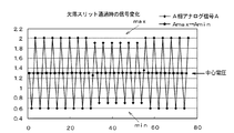
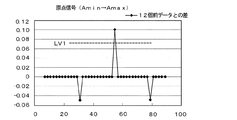
前記演算手段は、前記アナログ信号波形が1周期の中の最小値から最大値に変化する間の中間電圧又は前記アナログ信号波形が1周期の中の最大値から最小値に変化する間の中間電圧を前記受光部から出力されるアナログ信号波形の中心電圧とし、前記中心電圧の現在の値と前記所定の個数前のデータにおける中心電圧の値との差を求め、前記差が閾値を超えたことに基づいて前記原点位置を検出することを特徴とする。
振幅=Amax−Amin
中心電圧=(Amax+Amin)/2
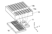
12 受光部
13 スケール
13a 反射部分
13b、13b’ 非反射部分
14 フォトダイオード
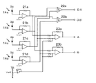
21 アナログ増幅器
22 コンパレータ
23 差動増幅器
A、B アナログ信号
DA、DB デジタル信号
Claims (4)
- 発光部と、前記発光部に対して相対移動が可能であり、所定の間隔で反射部分と前記反射部分の一部が欠落した非反射部分とを形成したスケールと、前記発光部で発光し前記スケールの反射部分で反射した光を受光し、受光する光の強度に応じた信号を出力する受光部と、前記スケールの相対移動に伴って前記スケールの非反射部分によってもたらされる前記信号の欠落に基づいて前記スケールの原点位置を演算によって求める演算手段と、を有するエンコーダにおいて、
前記受光部には位相の異なる複数のアナログ信号を出力する複数のフォトダイオードを配列した複数のセグメントを配列し、
前記スケールの非反射部分の幅が、前記反射部分のnピッチ分であり、前記所定の個数前のデータは、前記受光部のセグメント数−n+1であり、
前記演算手段は、前記アナログ信号波形が1周期の中の最小値から最大値に変化する間の中間電圧又は前記アナログ信号波形が1周期の中の最大値から最小値に変化する間の中間電圧を前記受光部から出力されるアナログ信号波形の中心電圧とし、前記中心電圧の現在の値と前記所定の個数前のデータにおける中心電圧の値との差を求め、前記差が閾値を超えたことに基づいて前記原点位置を検出することを特徴とするエンコーダ。 - 発光部と、前記発光部に対して相対移動が可能であり、所定の間隔で反射部分と前記反射部分の一部が欠落した非反射部分とを形成したスケールと、前記発光部で発光し前記スケールの反射部分で反射した光を受光し、受光する光の強度に応じた信号を出力する受光部と、前記スケールの相対移動に伴って前記スケールの非反射部分によってもたらされる前記信号の欠落に基づいて前記スケールの原点位置を演算によって求める演算手段と、を有するエンコーダにおいて、
前記受光部には位相の異なる複数のアナログ信号を出力する複数のフォトダイオードを配列した複数のセグメントを配列し、
前記スケールの非反射部分の幅が、前記反射部分のnピッチ分であり、前記所定の個数前のデータは、前記受光部のセグメント数+n−1であり、
前記演算手段は、前記アナログ信号波形が1周期の中の最小値から最大値に変化する間の中間電圧又は前記アナログ信号波形が1周期の中の最大値から最小値に変化する間の中間電圧を前記受光部から出力されるアナログ信号波形の中心電圧とし、前記中心電圧の現在の値と前記所定の個数前のデータにおける中心電圧の値との差を求め、前記差が閾値を超えたことに基づいて前記原点位置を検出することを特徴とするエンコーダ。 - 発光部と、前記発光部に対して相対移動が可能であり、所定の間隔で反射部分と前記反射部分の一部が欠落した非反射部分とを形成したスケールと、前記発光部で発光し前記スケールの反射部分で反射した光を受光し、受光する光の強度に応じた信号を出力する受光部と、前記スケールの相対移動に伴って前記スケールの非反射部分によってもたらされる前記信号の欠落に基づいて前記スケールの原点位置を演算によって求める演算手段と、を有するエンコーダにおいて、
前記受光部には位相の異なる複数のアナログ信号を出力する複数のフォトダイオードを配列した複数のセグメントを配列し、
前記スケールの非反射部分の幅が、前記反射部分のnピッチ分であり、前記所定の個数前のデータは、2×(前記受光部のセグメント数)−n+1であり、
前記演算手段は、前記アナログ信号波形が1周期の中の最小値から最大値に変化する間の中間電圧及び前記アナログ信号波形が1周期の中の最大値から最小値に変化する間の中間電圧を前記受光部から出力されるアナログ信号波形の中心電圧とし、前記中心電圧の現在の値と前記所定の個数前のデータにおける中心電圧の値との差を求め、前記差が閾値を超えたことに基づいて前記原点位置を検出することを特徴とするエンコーダ。 - 発光部と、前記発光部に対して相対移動が可能であり、所定の間隔で反射部分と前記反射部分の一部が欠落した非反射部分とを形成したスケールと、前記発光部で発光し前記スケールの反射部分で反射した光を受光し、受光する光の強度に応じた信号を出力する受光部と、前記スケールの相対移動に伴って前記スケールの非反射部分によってもたらされる前記信号の欠落に基づいて前記スケールの原点位置を演算によって求める演算手段と、を有するエンコーダにおいて、
前記受光部には位相の異なる複数のアナログ信号を出力する複数のフォトダイオードを配列した複数のセグメントを配列し、
前記スケールの非反射部分の幅が、前記反射部分のnピッチ分であり、前記所定の個数前のデータは、2×(前記受光部のセグメント数)+n−1であり、
前記演算手段は、前記アナログ信号波形が1周期の中の最小値から最大値に変化する間の中間電圧及び前記アナログ信号波形が1周期の中の最大値から最小値に変化する間の中間電圧を前記受光部から出力されるアナログ信号波形の中心電圧とし、前記中心電圧の現在の値と前記所定の個数前のデータにおける中心電圧の値との差を求め、前記差が閾値を超えたことに基づいて前記原点位置を検出することを特徴とするエンコーダ。
Priority Applications (4)
| Application Number | Priority Date | Filing Date | Title |
|---|---|---|---|
| JP2006257199A JP4928206B2 (ja) | 2006-09-22 | 2006-09-22 | エンコーダ |
| US11/854,941 US7425697B2 (en) | 2006-09-22 | 2007-09-13 | Origin detection method for optical encoder |
| EP07018090.6A EP1903314B1 (en) | 2006-09-22 | 2007-09-14 | Origin detection method for optical encoder |
| US12/193,208 US7732757B2 (en) | 2006-09-22 | 2008-08-18 | Origin detection method for optical encoder |
Applications Claiming Priority (1)
| Application Number | Priority Date | Filing Date | Title |
|---|---|---|---|
| JP2006257199A JP4928206B2 (ja) | 2006-09-22 | 2006-09-22 | エンコーダ |
Publications (3)
| Publication Number | Publication Date |
|---|---|
| JP2008076284A JP2008076284A (ja) | 2008-04-03 |
| JP2008076284A5 JP2008076284A5 (ja) | 2009-11-12 |
| JP4928206B2 true JP4928206B2 (ja) | 2012-05-09 |
Family
ID=38799358
Family Applications (1)
| Application Number | Title | Priority Date | Filing Date |
|---|---|---|---|
| JP2006257199A Expired - Fee Related JP4928206B2 (ja) | 2006-09-22 | 2006-09-22 | エンコーダ |
Country Status (3)
| Country | Link |
|---|---|
| US (2) | US7425697B2 (ja) |
| EP (1) | EP1903314B1 (ja) |
| JP (1) | JP4928206B2 (ja) |
Families Citing this family (10)
| Publication number | Priority date | Publication date | Assignee | Title |
|---|---|---|---|---|
| WO2008088650A1 (en) * | 2007-01-11 | 2008-07-24 | 3M Innovative Properties Company | Web longitudinal position sensor |
| JP2010530543A (ja) * | 2007-06-19 | 2010-09-09 | スリーエム イノベイティブ プロパティズ カンパニー | 変位スケールを製作するシステム及び方法 |
| US8405831B2 (en) * | 2007-06-19 | 2013-03-26 | 3M Innovative Properties Company | Systems and methods for indicating the position of a web |
| CN101680780A (zh) * | 2007-06-19 | 2010-03-24 | 3M创新有限公司 | 全内反射位移刻度尺 |
| US8847185B2 (en) | 2008-12-29 | 2014-09-30 | 3M Innovative Properties Company | Phase-locked web position signal using web fiducials |
| CN102272375B (zh) | 2008-12-30 | 2014-01-08 | 3M创新有限公司 | 用于在基底上形成基准的设备和方法 |
| JP2010256081A (ja) * | 2009-04-22 | 2010-11-11 | Fujifilm Corp | 光学式位置検出器及び光学装置 |
| JP6004626B2 (ja) | 2011-10-12 | 2016-10-12 | キヤノン株式会社 | エンコーダシステム、位置検出機能付き装置、および、複写機 |
| JP2014098666A (ja) * | 2012-11-15 | 2014-05-29 | Canon Inc | インクリメンタルエンコーダ |
| JP5822008B1 (ja) * | 2014-08-08 | 2015-11-24 | 日本精工株式会社 | 角度検出装置、この角度検出装置を備えるモータ、トルクセンサ、電動パワーステアリング装置及び自動車 |
Family Cites Families (12)
| Publication number | Priority date | Publication date | Assignee | Title |
|---|---|---|---|---|
| JP3254737B2 (ja) * | 1992-06-17 | 2002-02-12 | キヤノン株式会社 | エンコーダー |
| JP3227206B2 (ja) * | 1992-06-30 | 2001-11-12 | キヤノン株式会社 | 光学式エンコーダ |
| JPH0656304A (ja) | 1992-07-03 | 1994-03-01 | Nec Eng Ltd | 記録紙残量表示機構 |
| JP3170902B2 (ja) * | 1992-09-30 | 2001-05-28 | キヤノン株式会社 | 信号処理方法及びそれを用いたエンコーダ |
| US5929789A (en) * | 1997-04-09 | 1999-07-27 | Hewlett-Packrd Company | Single channel incremental position encorder with incorporated reference mark |
| DE60033075T3 (de) * | 1999-04-16 | 2012-08-30 | Canon K.K. | Kodierer |
| JP4428781B2 (ja) * | 1999-12-28 | 2010-03-10 | キヤノン株式会社 | 光学式ロータリエンコーダ及びモータ制御装置 |
| JP4726168B2 (ja) * | 2000-04-17 | 2011-07-20 | キヤノン株式会社 | 光学スケール及び光学式エンコーダ |
| JP2003161645A (ja) | 2001-11-28 | 2003-06-06 | Canon Inc | 光学式エンコーダ |
| JP4498024B2 (ja) * | 2004-06-15 | 2010-07-07 | キヤノン株式会社 | 光学式エンコーダ |
| JP4908764B2 (ja) * | 2005-02-04 | 2012-04-04 | キヤノン株式会社 | 光学式エンコーダ |
| DE102005006247A1 (de) | 2005-02-11 | 2006-08-17 | Dr. Johannes Heidenhain Gmbh | Positionsmesseinrichtung |
-
2006
- 2006-09-22 JP JP2006257199A patent/JP4928206B2/ja not_active Expired - Fee Related
-
2007
- 2007-09-13 US US11/854,941 patent/US7425697B2/en not_active Expired - Fee Related
- 2007-09-14 EP EP07018090.6A patent/EP1903314B1/en not_active Not-in-force
-
2008
- 2008-08-18 US US12/193,208 patent/US7732757B2/en not_active Expired - Fee Related
Also Published As
| Publication number | Publication date |
|---|---|
| US7425697B2 (en) | 2008-09-16 |
| EP1903314B1 (en) | 2017-01-04 |
| US7732757B2 (en) | 2010-06-08 |
| JP2008076284A (ja) | 2008-04-03 |
| EP1903314A3 (en) | 2013-04-17 |
| EP1903314A2 (en) | 2008-03-26 |
| US20090050794A1 (en) | 2009-02-26 |
| US20080073493A1 (en) | 2008-03-27 |
Similar Documents
| Publication | Publication Date | Title |
|---|---|---|
| US7425697B2 (en) | Origin detection method for optical encoder | |
| JP4498024B2 (ja) | 光学式エンコーダ | |
| EP2416126B1 (en) | Absolute encoder | |
| JP5011201B2 (ja) | 絶対位置測長型エンコーダ | |
| US20090283667A1 (en) | Absolute position length measurement type encoder | |
| US9200928B2 (en) | Position detector | |
| EP2199752B1 (en) | Absolute position encoder | |
| JP6533360B2 (ja) | 位置検出装置及びそれを有するレンズ装置及び撮影装置 | |
| CN102168996A (zh) | 光电式编码器 | |
| JP6149740B2 (ja) | アブソリュートエンコーダ | |
| US7184914B2 (en) | Sensor signal processor | |
| US7282699B2 (en) | Optical encoder for improved detection of the absolute position of an origin point | |
| JP5747342B2 (ja) | 光学式エンコーダ | |
| JP2015152408A (ja) | エンコーダ | |
| US9534936B2 (en) | Reference signal generation apparatus and reference signal generation system | |
| US9322675B2 (en) | Absolute encoder and method of obtaining absolute position by a plurality of quantized data based on a plurality of extrema | |
| JP2007071732A (ja) | 光学式絶対値エンコーダ | |
| JP4474188B2 (ja) | 光学式エンコーダ | |
| JP2007078357A (ja) | 光学式絶対値エンコーダ | |
| JP2004347358A (ja) | 変位測定装置 |
Legal Events
| Date | Code | Title | Description |
|---|---|---|---|
| A521 | Written amendment |
Free format text: JAPANESE INTERMEDIATE CODE: A523 Effective date: 20090918 |
|
| A621 | Written request for application examination |
Free format text: JAPANESE INTERMEDIATE CODE: A621 Effective date: 20090918 |
|
| RD01 | Notification of change of attorney |
Free format text: JAPANESE INTERMEDIATE CODE: A7421 Effective date: 20100218 |
|
| RD01 | Notification of change of attorney |
Free format text: JAPANESE INTERMEDIATE CODE: A7421 Effective date: 20100630 |
|
| A977 | Report on retrieval |
Free format text: JAPANESE INTERMEDIATE CODE: A971007 Effective date: 20110729 |
|
| A131 | Notification of reasons for refusal |
Free format text: JAPANESE INTERMEDIATE CODE: A131 Effective date: 20110802 |
|
| A521 | Written amendment |
Free format text: JAPANESE INTERMEDIATE CODE: A523 Effective date: 20110922 |
|
| A131 | Notification of reasons for refusal |
Free format text: JAPANESE INTERMEDIATE CODE: A131 Effective date: 20111018 |
|
| TRDD | Decision of grant or rejection written | ||
| A01 | Written decision to grant a patent or to grant a registration (utility model) |
Free format text: JAPANESE INTERMEDIATE CODE: A01 Effective date: 20120207 |
|
| A01 | Written decision to grant a patent or to grant a registration (utility model) |
Free format text: JAPANESE INTERMEDIATE CODE: A01 |
|
| A61 | First payment of annual fees (during grant procedure) |
Free format text: JAPANESE INTERMEDIATE CODE: A61 Effective date: 20120210 |
|
| FPAY | Renewal fee payment (event date is renewal date of database) |
Free format text: PAYMENT UNTIL: 20150217 Year of fee payment: 3 |
|
| FPAY | Renewal fee payment (event date is renewal date of database) |
Free format text: PAYMENT UNTIL: 20150217 Year of fee payment: 3 |
|
| LAPS | Cancellation because of no payment of annual fees |