JP4889167B2 - Cogeneration system operation planning method - Google Patents
Cogeneration system operation planning method Download PDFInfo
- Publication number
- JP4889167B2 JP4889167B2 JP2001242211A JP2001242211A JP4889167B2 JP 4889167 B2 JP4889167 B2 JP 4889167B2 JP 2001242211 A JP2001242211 A JP 2001242211A JP 2001242211 A JP2001242211 A JP 2001242211A JP 4889167 B2 JP4889167 B2 JP 4889167B2
- Authority
- JP
- Japan
- Prior art keywords
- power
- heat
- load
- output
- cogeneration
- Prior art date
- Legal status (The legal status is an assumption and is not a legal conclusion. Google has not performed a legal analysis and makes no representation as to the accuracy of the status listed.)
- Expired - Fee Related
Links
Images


Classifications
-
- Y—GENERAL TAGGING OF NEW TECHNOLOGICAL DEVELOPMENTS; GENERAL TAGGING OF CROSS-SECTIONAL TECHNOLOGIES SPANNING OVER SEVERAL SECTIONS OF THE IPC; TECHNICAL SUBJECTS COVERED BY FORMER USPC CROSS-REFERENCE ART COLLECTIONS [XRACs] AND DIGESTS
- Y02—TECHNOLOGIES OR APPLICATIONS FOR MITIGATION OR ADAPTATION AGAINST CLIMATE CHANGE
- Y02E—REDUCTION OF GREENHOUSE GAS [GHG] EMISSIONS, RELATED TO ENERGY GENERATION, TRANSMISSION OR DISTRIBUTION
- Y02E20/00—Combustion technologies with mitigation potential
- Y02E20/14—Combined heat and power generation [CHP]
-
- Y—GENERAL TAGGING OF NEW TECHNOLOGICAL DEVELOPMENTS; GENERAL TAGGING OF CROSS-SECTIONAL TECHNOLOGIES SPANNING OVER SEVERAL SECTIONS OF THE IPC; TECHNICAL SUBJECTS COVERED BY FORMER USPC CROSS-REFERENCE ART COLLECTIONS [XRACs] AND DIGESTS
- Y02—TECHNOLOGIES OR APPLICATIONS FOR MITIGATION OR ADAPTATION AGAINST CLIMATE CHANGE
- Y02T—CLIMATE CHANGE MITIGATION TECHNOLOGIES RELATED TO TRANSPORTATION
- Y02T10/00—Road transport of goods or passengers
- Y02T10/10—Internal combustion engine [ICE] based vehicles
- Y02T10/12—Improving ICE efficiencies
Description
【0001】
【発明の属する技術分野】
本発明は、電力と熱とを発生するコジェネレーション装置と、前記発生した電力を受電電力と合わせて施設に供給する配電手段と、前記発生した熱を、蓄熱した後に前記施設に供給する配熱手段とを備えたコジェネレーションシステム、及びそのコジェネレーションシステムにおいて、前記コジェネレーション装置の運転計画を行なう運転計画方法に関する。
【0002】
【従来の技術】
最近、マンション等の集合住宅におけるコジェネレーションシステムの導入が増えてきている。このようなコジェネレーションシステムは、電力及び熱を出力するコジェネレーション装置として、ガスエンジン又はガスタービン等の原動機を駆動源として利用する発電機や燃料電池等を備え、出力した電力を、電力供給業者から受電した電力と合わせて各住居に供給すると共に、出力した熱を各住居に供給するように構成することができる。
【0003】
このようなコジェネレーション装置は、集合住宅等の施設において、電力負荷が高いと推測される所定の電力負荷ピーク時間帯に運転される。そして、その高い電力負荷の一部を、コジェネレーション装置の電力出力で補うことで、電力供給業者との契約電力負荷を低く押えることができ、さらに、そのときに出力する熱をも利用することができるため、省エネルギ性及び経済性の点で有効である。
【0004】
また、このようなコジェネレーション装置の上記所定の運転時間帯は、従来、施設へのコジェネレーションシステムの設置を計画する際に決定される。即ち、その設置計画時に、その施設の規模等から予測される施設の電力負荷及び熱負荷に対して、省エネルギ性及び経済性を発揮することができる運転時間帯がエネルギシミュレーション等により求められ、コジェネレーションシステムを設置した後は、このように求めた一定の運転時間帯にコジェネレーション装置が運転される。
【0005】
一方、このようなコジェネレーション装置は、商用電力系統(送電線配電線)と連系し、電力系統への逆潮流無しで運転されることが多いので、逆潮流が発生しないように、常に一定以上の電力を電力供給業者から受電するように電力出力を制御した所謂電主運転を行なうように構成される。
【0006】
【発明が解決しようとする課題】
このように上記所定の時間帯に上記電主運転されるコジェネレーション装置からの熱出力は、施設の熱負荷には一致しておらず、さらに、1日における熱出力の積算値も、施設の熱負荷の積算値にも一致していない。
【0007】
よって、上記熱出力の上記熱負荷に対する不一致を緩和すべく、コジェネレーション装置から出力した熱を、一旦水等との熱交換により蓄熱して、その蓄熱した温水を施設に供給することが考えられるが、上記熱出力の上記積算値の不一致のために、不足熱を補充するべく温水を追い焚きしたり、余剰熱を消費せずに排出することがあり、このことは、省エネルギ性及び経済性の向上を阻害する要因となる。
【0008】
よって、本発明は、上記のような事情に鑑みて、簡単な構成で、省エネルギ性及び経済性を向上するように、コジェネレーション装置の最適な運転計画を行なう技術を実現することを目的とする。
【0009】
【課題を解決するための手段】
〔構成1〕
本発明に係るコジェネレーション装置の運転計画方法は、請求項1に記載したごとく、
計測手段により計測され記憶手段に記憶された、過去の前記施設の電力負荷実績及び熱負荷実績から、前記運転計画の計画対象時期における前記施設の予測電力負荷及び予測熱負荷を予測する負荷予測工程と、
前記予測電力負荷がコジェネレーション装置の定格運転時の電力出力よりも、電力の逆潮流防止のための受電電力以上大きい場合には定格運転を行ない、それ以外の場合には前記電力出力が前記予測電力負荷よりも一定量小さくなる電主運転を行なうものとして、前記コジェネレーション装置の熱出力を導出する熱出力導出工程と、
前記予測熱負荷の前記計画対象時期における積算値である予測積算熱負荷と、前記熱出力の運転時間帯における積算値である積算熱出力とを比較して、前記計画対象時期において前記コジェネレーション装置の電主運転を行なう前記運転時間帯を決定する運転時間帯決定工程とを実行し、
前記運転時間帯決定工程は、前記予測積算熱負荷と前記積算熱出力とが同等となるように、所定の運転終了時間に対する運転開始時間を決定し、
前記運転開始時間は、前記所定の運転終了時間からさかのぼって前記コジェネレーション装置の出力が前記定格運転時の電力出力であり、且つ、そのときの前記予測熱負荷が、前記熱出力よりも大きい最も早い時間よりも以前の時間とすることを特徴とする。
【0010】
〔作用効果〕
本発明のコジェネレーション装置の運転計画方法は、前記コジェネレーション装置の運転を行なう運転制御手段を備えた制御装置等に内蔵又は外付けされたコンピュータにより実行されるものであり、前記計画対象時期において、前記運転制御手段がコジェネレーション装置の電主運転を行なう運転時間帯を決定するためのものである。
【0011】
そして、本構成のコジェネレーション装置の運転計画方法によれば、まず、負荷予測工程において、前記施設に設けられた電力負荷計測手段及び熱負荷計測手段から逐次記憶手段に格納して収集された過去の施設の電力負荷実績及び熱負荷実績から、当日又は来日等の計画対象時期における施設の予測電力負荷及び予測熱負荷を予測することができる。
【0012】
そして、前記熱出力導出工程において、予測した予測電力負荷に対して、コジェネレーション装置の電主運転を行なうときの熱出力を導出することができる。尚、電主運転とは、上記予測電力負荷において電力負荷がコジェネレーションの定格運転時の電力出力よりも充分大きい場合には定格運転を行ない、それ以外の場合には常に電力出力が電力負荷よりも一定量小さくなる電力追従運転を行なう運転であり、このようにコジェネレーション装置を電主運転することで、常に一定以上の電力を電力供給業者から受電するように電力出力が制御され、電力系統への逆潮流が防止される。
【0013】
さらに、前記運転時間帯決定工程において、前記施設の前記予測熱負荷に対して、効率良くコジェネレーション装置から熱を出力させることができるように、予測熱負荷と熱出力とを比較して、コジェネレーション装置の運転時間帯を決定することができる。
よって、計画対象時期において、このように決定された運転時間帯にコジェネレーション装置を電主運転することで、コジェネレーション装置から出力された熱をできるだけ無駄無く施設で消費することができ、省エネルギ性及び経済性を向上することができる。
従って、コジェネレーション装置の最適な運転計画を行なう運転計画方法を実現することができる。
【0014】
【0015】
そして、本構成のコジェネレーション装置の運転計画方法によれば、前記運転時間決定工程で決定された運転時間帯において、コジェネレーション装置を電主運転した場合に、決定された運転時間帯におけるコジェネレーション装置からの積算熱出力が、予測積算熱負荷と同等となるので、配熱手段において熱の過不足をできるだけ低減して、効率良くコジェネレーション装置の熱出力を消費することができる。
【0016】
【0017】
【0018】
【0019】
また、施設において、電力負荷が大きくなる電力負荷ピーク時間帯はほぼ決まった時間帯であることが多く、例えば施設がマンション等の集合住宅である場合には、その電力ピーク時間帯は夜間にあり、深夜(24時頃)にはそれが終了する。
このように、ほぼ決まった時間帯に電力負荷ピーク時間帯がある施設においては、本構成のごとく、前記運転時間帯決定工程において、コジェネレーション装置の運転を終了する運転終了時間を予め設定しておき、その運転終了時間に対して前記コジェネレーション装置の運転開始時間を決定することで、運転時間帯を決定することができ、簡単な構成で本発明に係るコジェネレーション装置の運転計画方法を実現することができる。
【0020】
〔構成2〕
本発明に係るコジェネレーション装置の運転計画方法は、請求項2に記載したごとく、上記構成1のコジェネレーション装置の運転計画方法の構成に加えて、前記運転時間帯決定工程において、前記運転時間帯の時間長さが所定の最大時間長さ以下に制限されていることを特徴とする。
【0021】
〔作用効果〕
本構成のごとく、一日における前記運転時間帯の時間長さを前記最大時間長さ以下に制限することで、施設の予測熱負荷が増大しても、コジェネレーション装置の運転時間が一定時間以下に制限されるので、コジェネレーション装置を酷使することがなく、コジェネレーション装置の予め設定した耐用年数を維持することができる。
【0022】
〔構成3〕
本発明に係るコジェネレーション装置の運転計画方法は、請求項3に記載したごとく、上記構成1又は2の何れかのコジェネレーション装置の運転計画方法の構成に加えて、前記負荷予測工程が、前記施設の環境条件をパラメータとして、前記電力負荷実績及び前記熱負荷実績から、前記予測電力負荷及び前記予測熱負荷を予測する工程であることを特徴とする。
【0023】
〔作用効果〕
前記負荷予測工程で予測される電力又は熱の予測負荷は、予測基準とした過去の気温、降水量、若しくは湿度等の気象条件、曜日等のカレンダ条件、又は施設の住居者数又は集合住宅における入居率等の住居条件等の環境条件と、予測対象の計画対象時期の環境条件との差により、実際の計画対象時期の負荷実績に対して差が生じることがある。
【0024】
そこで、コジェネレーションシステムに、前記環境条件を収集する手段を設け、本構成のごとく、前記負荷予測工程において、例えば、計画対象時期のある環境条件と同様な環境条件であった過去の電力及び熱の負荷実績を記憶手段から抽出し、その抽出した負荷実績を計画対象時期の予測負荷とすることで、上記環境条件をパラメータとして計画対象時期の予測負荷を予測することができる。そして、このように予測された予測電力負荷及び予測熱負荷は、その計画対象時期における実際の負荷と近いものになる。よって、この予測負荷実績を用いて計画したコジェネレーション装置の運転時間帯は、環境条件の変化による施設の負荷変動をも考慮され、且つ施設の実際の電力及び熱の負荷に適したものとなり、環境条件の変化によるコジェネレーションシステムの省エネルギ性及び経済性の低下を抑制することができる。
【0025】
尚、上記環境条件を収集する手段は、人手による手入力の他、施設に設けた気温計又は湿度計等から記憶又は湿度等の気象条件を収集したり、コンピュータの時間計測機能等から月又は曜日等のカレンダ情報を収集するように構成することができる。また、上記計画対象時期の予測環境条件としては、計画対象時期が始まる前の時点における上記環境条件を利用できる。
さらに、1つの環境条件をパラメータとして抽出した過去の負荷実績を、その過去と計画対象時期との間の他の環境条件の差を用いて補正したものを、予測負荷とすることもでき、予測負荷を計画対象時期における実際の負荷に対してより近いものとすることができる。
【0026】
〔構成4〕
本発明に係るコジェネレーション装置の運転計画方法は、請求項4に記載したごとく、上記構成1から3の何れかのコジェネレーション装置の運転計画方法の構成に加えて、前記施設が、複数の住居からなる集合住宅であり、
前記配熱手段が、前記出力した熱により加熱した温水を前記各住居に設けられた給湯器の給水として供給するように構成されていることを特徴とする。
【0027】
〔作用効果〕
複数の住居からなるマンション等の集合住宅は、各住居における電力及び熱の消費状態が夫々異なり、さらに日々変化する。よって、このような集合住宅にコジェネレーション装置を設ける場合、コジェネレーション装置の運転時間帯を毎日同じ一定の時間帯とすると、その電力及び熱の消費状態の変化により、省エネルギ性及び経済性が低下してしまうことがある。よって、特に集合住宅の場合は、本発明にかかるコジェネレーション装置の運転計画方法により、その集合住宅における電力及び熱の予測負荷を予測して、一日毎にコジェネレーション装置の運転計画を行なうことが好ましい。
また、本構成のごとく、このように集合住宅にコジェネレーション装置を設ける場合、配熱手段を、各住居に設けられた給湯器に供給する給水として、コジェネレーション装置の熱出力で加熱した温水を追い焚き等をしないで供給するように構成することで、各住居の給湯器におけるガスの消費量を節約することができ、有効にコジェネレーション装置の熱出力を消費することができる。
【0028】
【発明の実施の形態】
本発明のコジェネレーション装置の運転計画方法の実施の形態について、図面に基づいて説明する。
図1は、複数の住居20からなる集合住宅に、コジェネレーションシステム50を設けた場合の全体構成図である。
このようなコジェネレーションシステム50は、集合住宅における共有資産であり、集合住宅の管理組合又はそれから委託された管理業者等が運営管理する。
【0029】
一般的に、各住居20には、電力を消費する電灯、空調設備等の電力消費部22や、給湯器21から供給される湯水を消費するカラン、温水床暖房機、風呂、浴室暖房乾燥機等の湯水消費部23や、ガスを消費するコンロ等のガス消費部24や、水道から供給される水を消費するカラン等の水消費部25等が存在する。また、集合住宅の共有部には、外灯、エレベータ等の電力消費部30が存在する。
【0030】
この集合住宅において消費される電力としては、電力供給業者から一括受電された電力と、後述のコジェネレーション装置1から出力した電力とが利用され、上記電力は、その業者が設置した電力メータ6及びコジェネレーションシステム50に設けられた変電設備9を介して受電される。
そして、電力供給業者は、電力メータ6を検針し、電力の電力単価に基づいて、集合住宅全体の電力料金を計算し、その電力料金を集合住宅の管理組合等に課金する。
【0031】
また、各住居20で消費される電力は、各住居20に設けられた電力メータ26(電力負荷計測手段の一例)により計測される。そして、集合住宅の管理組合等は、その電力メータ26を毎月検針して、電力供給業者が設定する電力の電力単価又は従量電灯の電力単価等に基づいて、管理組合等が設定する料金体系で、各住居20の電力料金を計算し、各住居20側へ課金する。また、共有部の電力消費部30で消費される電力は、共益費として各住居20側へ課金される。尚、このようにコジェネレーション装置1で出力した電力を受電電力と合わせて各住居20に供給する手段を配電手段と呼ぶ。
【0032】
また、集合住宅の各住居20において消費されるガス及び水は、ガス供給業者及び水道業者から、その業者が設置したガスメータ28及び水道メータ29を介して各住居20に供給される。そして、夫々の供給業者は、夫々のメータ28,29を検針し、夫々の単価に基づいて、各住居20夫々の料金を計算し、その料金を各住居20又はそれを一括管理する管理組合等に課金する。
【0033】
同様に、コジェネレーションシステム50にも、ガス供給業者及び水道業者から、ガス及び水が、その業者が設置したガスメータ7及び水道メータ8を介して供給される。そして、同様に、夫々の業者は、そのガス料金及び水道料金を管理組合等に課金する。
【0034】
上記ガスメータ7を介してコジェネレーションシステム50に供給されたガスは、コジェネレーション装置1に供給される。コジェネレーション装置1は、ガスエンジンやガスタービンや燃料電池等のように、ガスを消費して電力と熱とを出力するものであり、このように出力された電力は、上記一括受電した電力と合わせて、各住居20等に供給される。
【0035】
上記水道メータ8を介してコジェネレーションシステム50に供給された水は、コジェネレーション装置1から出力された熱により加熱された温水を貯留する貯湯槽2に供給される。即ち、コジェネレーションシステム50には、コジェネレーション装置1から出力された熱との熱交換により水を加熱する熱交換器4と、内部に貯留する水を循環ポンプ5により熱交換器4側に循環させて加熱させ、その加熱された温水を貯留する貯湯槽2と、その貯湯槽2に貯留された温水を各住居20に供給するための供給ポンプ3と、各住居20に供給された温水量を計測する温水メータ27とが設けられている。また、この温水を各住居20に供給して水位が下がった貯湯槽2には、その水位が下がった分の水が、水道業者から水道メータ8を介して供給される。尚、このようにコジェネレーション装置1で出力した熱を、温水として蓄熱して、その蓄熱した熱を、温水として各住居20へ供給する手段を配熱手段と呼ぶ。
【0036】
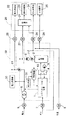
コジェネレーション装置1は、CPUを設けたコンピュータで構成された制御装置10によって運転開始及び停止及び出力調整等の運転制御が行われる。尚、制御装置10に設けられる後述の各手段は、CPUが予めハードディスク等の記憶手段14に格納されたプログラムを実行することで実現されるものである。
【0037】
制御装置10は、図2に示すように、電力供給業者からの電力受電点に設けられた電力メータ6と、各住居20に設けられた電力メータ26及び温水メータ27との夫々の計測結果が入力される入力部16と、コジェネレーション装置1を運転制御するための指令信号が出力される出力部17とが設けられている。
さらに、制御装置10には、一定時間毎に、上記電力メータ26から各住居20に供給した電力を電力負荷として収集し、さらに、上記温水メータ27から収集した各住居20に供給した温水量の和と、貯湯槽2内に設けられた温度センサ(図示せず)から収集した温水の温度とから、集合住宅における熱負荷を算出して、このようにして得た電力負荷と熱負荷とから、その日の電力負荷の経時的変化を示す電力負荷データと、その日の熱負荷の経時的変化を示す熱負荷データとを生成して、記憶手段14に格納する負荷データ生成手段11が設けられている。尚、上記温水メータ27及び貯湯槽2内の温度センサのように、集合住宅における熱負荷を計測する手段を熱負荷計測手段と呼ぶ。
尚、電力負荷を収集するために、電力消費部30の分岐点よりも下手側の電力線において、各住居20に分岐する手前に電力メータ61を設けて、この電力メータ61から電力負荷を収集するようにしても、受電点に設けられた電力メータ6での計測値を用いてもよい。
又、熱負荷を算出するための温水量としては、各住居20側に設けた温水メータ27の計測値を用いるのではなく、貯湯槽2からの温水供給路における各住居20に分岐する手前に設けた温水メータ71の計測値を用いてもよい。
【0038】
さらに、コジェネレーションシステム50には、外気温、水道業者から供給される水の温度等の外部環境条件を検出する環境条件検出手段31が設けられ、この環境条件検出手段31の検出結果が、制御装置10に送られる。
そして、制御装置10は、その検出された環境条件も、上記負荷データに関連付けて記憶手段14に格納する。
【0039】
さらに、制御装置10の記憶手段14には、1日におけるコジェネレーション装置1の運転時間帯に関する運転スケジュールデータが格納されている。
そして、制御装置10の運転制御手段13は、その記憶手段14に格納された運転スケジュールデータに基づいて、前記コジェネレーション装置1の運転を開始及び停止させる。さらに、運転制御手段13は、各住居20の電力メータ26で計測された電力の和(電力負荷)がコジェネレーション装置1の定格運転時の電力出力よりも充分大きい場合には定格運転を行ない、それ以外の場合には常に電力出力が電力負荷よりも所定量小さくなる電力追従運転を行なう、所謂電主運転を行なうように、コジェネレーション装置1に投入するガス流量等を調整し、コジェネレーション装置1の運転を制御する。
尚、上記の電主運転に際して用いる電力負荷の計測にあたっては、受電点に設けられた電力メータ6での計測値を用いてもよい。
【0040】
また、上記記憶手段14に格納されている運転スケジュールデータは、制御装置10に設けられた運転計画手段12により実行される運転計画方法により生成されたものであり、その運転計画方法の処理フローについて、図3に基づいて説明する。
【0041】
制御装置10に設けられた運転計画手段12は、コジェネレーション装置1の運転を行なわない午前中の所定の時間に、コジェネレーション装置1の午後(計画対象時期の一例)における運転時間帯を計画する上記運転計画方法を実行する。
この運転計画方法においては、まず、上記環境条件検出手段31により、その運転計画を行なう時点の外気温、水道業者から供給される水の温度等の外部環境条件を取得する(工程100)。
【0042】
次に、記憶手段14にアクセスして、上記計測した環境条件をパラメータとして、同じ時期(例えば同じ月等)に、同等の環境条件が計測された過去の電力負荷データ及び熱負荷データを抽出し(工程101)、その抽出した夫々の負荷データを、当日の予測電力負荷データ及び予測熱負荷データとして生成する(工程102)。このように生成された予測負荷データは、図4のグラフ図に示すように、当日の時間毎の予測電力負荷、及び図5のグラフ図に示すように、当日の時間毎の予測熱負荷から構成される。上記工程101及び工程102のように、計測された過去の電力負荷及び熱負荷の経時的変化を示すデータから、集合住宅における予測電力負荷及び予測熱負荷の経時的変化を示す予測負荷データを生成する工程を負荷予測工程と呼ぶ。
【0043】
また、このように過去の電力又は熱負荷データを抽出する場合には、当日と同じ曜日又は祝日である過日の各負荷データを抽出することが好ましく、夫々の予測負荷データを実際の当日の集合住宅における負荷データに近いものとすることができる。
【0044】
次に、運転計画手段12は、このように生成された予測電力負荷データに対するコジェネレーション装置1の電主運転をシミュレートし(工程103)、そのシミュレート結果から、このように電主運転させた場合にコジェネレーション装置1から出力される熱出力である熱出力データを生成する(工程104)。
【0045】
上記電主運転のシミュレートにおいては、コジェネレーション装置1の電力出力が、定格出力以下で、且つ逆潮流を防止するべく上記予測電力負荷によりも常に一定以上小さいときのコジェネレーション装置1の運転条件が求められ、この運転条件から、このような電主運転を行なったときのコジェネレーション装置1の上記熱出力が求められる。
上記工程103及び工程104のように、予測電力負荷に対する電主運転を行なった場合のコジェネレーション装置1の熱出力としての熱出力データを生成する工程を熱出力導出工程と呼ぶ。
【0046】
次に、運転計画手段12は、詳細については後述するが、上記生成した熱出力データと、上記予測した予測熱負荷データとを比較し(工程105)、当日におけるコジェネレーション装置1の電主運転を行なう運転時間帯を決定し(工程106)、その決定した運転時間帯に基づいて、上記記憶手段14に記憶してある運転スケジュールデータを更新する(工程107)。そして、制御装置10の運転制御手段13は、このように更新された運転スケジュールデータに基づいて、コジェネレーション装置1の運転開始及び運転停止を行い、さらに、運転時においては、上記のシミュレート結果である電主運転時の運転条件に基づいて、コジェネレーション装置1を電主運転させるのである。
【0047】
また、運転計画手段12は、コジェネレーション装置1を酷使することなく、コジェネレーション装置1の予め設定した耐用年数を維持するために、上記工程106において、決定する運転時間帯の時間長さを、予め設定されている最大時間長さ以下となるように制限することができる。
さらに、運転計画手段12は、コジェネレーション装置1を、できるだけ高効率な定格運転又はそれに近い運転状態のときを選択して運転するために、上記シミュレート結果において、コジェネレーション装置1の電力出力が定格出力又は予め設定されている出力以上となる時間が最大となるように、上記運転時間帯を決定することができる。
【0048】
以下に、運転計画手段12が運転時間帯を決定する詳細について説明する。
本実施形態においては、コジェネレーション装置1の運転停止時間は、不変的に予め24時に設定されている。そして、運転計画手段12は、コジェネレーション装置1の運転開始時間を決定することで、上記運転時間帯を決定する。これは、集合住宅における電力負荷及び熱負荷は、図4及び図5に示すように、一般的に夜間の21時前後に最も大きくなり、24時に向って減少するので、この時間帯をカバーするようにコジェネレーション装置1を運転すれば効率良く電力出力及び熱出力を集合住宅で消費できるからである。
【0049】
そして、運転計画手段12は、まず、コジェネレーション装置1の運転停止を行なう24時からさかのぼって、コジェネレーション装置1の電力出力が、定格出力であり、且つ、そのときの予測熱負荷が、コジェネレーション装置1の熱出力よりも大きい最も早い時間(図4及び図5を参照して、19時程度がその時間であるといえる。)よりも以前の時間を、上記コジェネレーション装置1の運転開始時間とする。
即ち、このような時間は、コジェネレーション装置1の運転状態を、最も効率が良い定格運転状態としても、その電力出力及び熱出力が予測電力負荷及び予測熱負荷を超えることがないので、効率良くコジェネレーション装置1の電力出力及び熱出力を、集合住宅において消費できる時間である。図4及び図5においては、19時程度がその時間であるといえる。
【0050】
また、集合住宅において、上記のように、コジェネレーション装置1の運転停止時間を不変的に24時に設定し、その24時からさかのぼってコジェネレーション装置1の出力が定格出力である最も早い時間よりも以前の時間を運転開始時間とすることで、コジェネレーション装置1の運転時間帯において、コジェネレーション装置1の出力を定格出力として、高効率で運転することができる時間を最大とすることができる。
【0051】
さらに、運転計画手段12は、その時間からさかのぼって、コジェネレーション装置1の運転時間帯における熱出力の積算値が、その運転時間帯における予測熱負荷の積算値、又は、当日における予測熱負荷の積算値と等しくなる時間(図5を参照して、14時がその時間であるといえる。)を求め、その時間をコジェネレーション装置1の運転開始時間とし、この運転開始時間(14時)から、予め設定されている運転停止時間(24時)までを、コジェネレーション装置1の運転時間帯として決定する。
【0052】
即ち、このように決定した運転時間帯は、少なくともコジェネレーション装置1を最も効率のよい定格運転することができる時間帯(19時から24時)を含むと共に、この運転時間帯で出力し蓄熱された熱量、即ち熱出力の積算値は、その運転時間帯又は当日の熱負荷の積算値に近いものとなり、集合住宅において効率よく熱出力を消費することができる。尚、上記のように14時から19時までの間において、コジェネレーション装置1は、電力追従運転を行なう。
【0053】
尚、上記のように、コジェネレーション装置1の運転停止を行なう時間からさかのぼって、コジェネレーション装置1の運転開始を行なう時間を求める場合には、上記電力と熱負荷の予測、及びコジェネレーション装置1の電主運転のシミュレート、及び運転時間帯の決定を、上記停止時間からさかのぼって一定時間毎(例えば1時間毎)を計画時間帯として繰り返し行なっても構わない。
【0054】
また、上記実施の形態において、上記環境条件検出手段31により計測した外気温、水道業者から供給される水の温度等の外部環境条件をパラメータとして、同じ時期に同等の環境条件が計測された過去の電力負荷データ及び熱負荷データを、当日の予測電力負荷データ及び予測熱負荷データとして生成したが、上記環境条件検出手段31の代わりに、インターネット端末等により、当日の予測気温、予測湿度、予測水温等の環境条件を、気象情報提供業者が運営するホームページ等から収集するように構成しても構わない。さらに、過去の電力負荷データ及び熱負荷データを、過去と現在における上記パラメータ以外の環境条件の差を用いて補正して、上記予測電力負荷データ及び予測熱負荷データの信頼性を向上させることもできる。尚、上記補正は、予め統計等に基づいて決定した上記環境条件の差に対する補正係数を、過去の負荷データにかけることで実施することができる。
【図面の簡単な説明】
【図1】 集合住宅に設けられたコジェネレーションシステムの全体構成図
【図2】 コジェネレーションシステムに設けられた制御装置の概略構成図
【図3】 運転計画方法の処理フローを示すフロー図
【図4】 予測電力負荷と電力出力との経時的変化を示すグラフ図
【図5】 予測熱負荷と熱出力との経時的変化を示すグラフ図
【符号の説明】
1 コジェネレーション装置
2 貯湯槽
3 供給ポンプ
4 熱交換器
5 循環ポンプ
6 電力メータ
7 ガスメータ
8 水道メータ
9 変電設備
10 制御装置
11 負荷データ生成手段
12 運転計画手段
13 運転制御手段
14 記憶手段
20 住居
21 給湯器
22 電力消費部
23 湯水消費部
24 ガス消費部
25 水消費部
26 電力メータ(電力負荷計測手段)
27 温水メータ(熱負荷計測手段)
28 ガスメータ
29 水道メータ
30 電力消費部
50 コジェネレーションシステム
61 電力メータ
71 温水メータ[0001]
BACKGROUND OF THE INVENTION
The present invention relates to a cogeneration apparatus that generates electric power and heat, power distribution means that supplies the generated power to the facility together with received power, and heat distribution that supplies the generated heat to the facility after storing the heat. A cogeneration system comprising means, and an operation planning method for performing an operation plan of the cogeneration apparatus in the cogeneration system.
[0002]
[Prior art]
Recently, the introduction of cogeneration systems in apartment houses such as condominiums has increased. Such a cogeneration system includes a generator or a fuel cell that uses a prime mover such as a gas engine or a gas turbine as a drive source as a cogeneration device that outputs electric power and heat, and the output electric power is supplied to a power supplier. It can be configured to supply each residence together with the power received from the power and supply the output heat to each residence.
[0003]
Such a cogeneration device is operated in a predetermined power load peak time zone in which a power load is estimated to be high in a facility such as a housing complex. And by supplementing part of the high power load with the power output of the cogeneration device, the contract power load with the power supplier can be kept low, and the heat output at that time can also be used Therefore, it is effective in terms of energy saving and economical efficiency.
[0004]
Further, the predetermined operation time zone of such a cogeneration apparatus is conventionally determined when planning the installation of a cogeneration system in a facility. That is, at the time of the installation plan, an operation time zone in which energy saving and economic efficiency can be exhibited with respect to the power load and heat load of the facility predicted from the scale of the facility is obtained by energy simulation, etc. After the cogeneration system is installed, the cogeneration apparatus is operated during the fixed operation time period obtained as described above.
[0005]
On the other hand, such a cogeneration device is connected to a commercial power system (transmission line distribution line) and is often operated without a reverse power flow to the power system. It is configured to perform a so-called main operation in which the power output is controlled so as to receive the above power from the power supplier.
[0006]
[Problems to be solved by the invention]
As described above, the heat output from the cogeneration apparatus operated mainly in the predetermined time zone does not match the heat load of the facility, and the integrated value of the heat output in one day is It does not match the integrated value of heat load.
[0007]
Therefore, in order to alleviate the discrepancy between the heat output and the heat load, the heat output from the cogeneration device is temporarily stored by heat exchange with water or the like, and the stored hot water is supplied to the facility. However, because of the discrepancy between the integrated values of the heat outputs, the hot water may be replenished to replenish the insufficient heat or may be discharged without consuming excess heat. It becomes a factor that hinders the improvement of sex.
[0008]
Therefore, in view of the circumstances as described above, an object of the present invention is to realize a technique for performing an optimal operation plan of a cogeneration apparatus so as to improve energy saving and economy with a simple configuration. To do.
[0009]
[Means for Solving the Problems]
[Configuration 1]
The operation planning method for the cogeneration apparatus according to the present invention is as described in
A load prediction step of predicting the predicted power load and predicted heat load of the facility at the planning target time of the operation plan from the past power load record and heat load record of the facility measured by the measuring unit and stored in the storage unit When,
Predicted power loadIs higher than the power output at the time of rated operation of the cogeneration device, the rated operation is performed when the received power is greater than the received power for preventing reverse power flow, otherwise the power output is higher than the predicted power load. As an electric main operation that reduces a certain amount,A heat output deriving step for deriving a heat output of the cogeneration device;
The predicted heat load that is the integrated value of the predicted heat load at the planning target time is compared with the integrated heat output that is the integrated value of the heat output during the operation time period, and the cogeneration apparatus is configured at the planning target time. And an operation time zone determination step for determining the operation time zone in which the main operation of the vehicle is performedAnd
The operation time zone determination step determines an operation start time with respect to a predetermined operation end time so that the predicted integrated heat load and the integrated heat output are equal,
The operation start time is the power output at the rated operation when the output of the cogeneration device is traced back from the predetermined operation end time, and the predicted heat load at that time is the largest than the heat output. To be earlier than earlierIt is characterized by.
[0010]
[Function and effect]
The operation planning method for a cogeneration apparatus according to the present invention is executed by a computer built in or externally attached to a control apparatus or the like having an operation control means for operating the cogeneration apparatus. The operation control means determines an operation time zone in which the main operation of the cogeneration apparatus is performed.
[0011]
And according to the operation planning method of the cogeneration apparatus of this configuration, first, in the load prediction step, the past collected and stored in the storage means sequentially from the power load measuring means and the thermal load measuring means provided in the facility It is possible to predict the predicted power load and predicted heat load of the facility at the planning target time such as the day of coming to Japan or the like from the power load record and the heat load record of the facility.
[0012]
And in the said heat output derivation | leading-out process, the heat output at the time of performing the electric main driving | operation of a cogeneration apparatus with respect to the estimated prediction electric power load can be derived | led-out. Note that the main operation means that if the power load is sufficiently larger than the power output during the rated operation of the cogeneration in the predicted power load, the rated operation is performed, and in other cases, the power output is always higher than the power load. In this way, the power output operation is controlled so that a certain amount of power is always received from the power supplier by operating the cogeneration system as the main power. The reverse power flow to is prevented.
[0013]
Furthermore, in the operation time zone determination step, the predicted heat load is compared with the heat output so that heat can be efficiently output from the cogeneration apparatus with respect to the predicted heat load of the facility. The operation time zone of the generation device can be determined.
Therefore, the main operation of the cogeneration device during the operation time period determined in this way during the planned time period allows the heat output from the cogeneration device to be consumed at the facility as much as possible, saving energy. And economic efficiency can be improved.
Therefore, it is possible to realize an operation planning method for performing an optimal operation plan for the cogeneration apparatus.
[0014]
[0015]
And according to the operation planning method of the cogeneration device of this configuration, when the cogeneration device is operated in the main operation in the operation time zone determined in the operation time determination step, the cogeneration in the determined operation time zone Since the integrated heat output from the apparatus is equivalent to the predicted integrated heat load, the heat output of the cogeneration apparatus can be efficiently consumed by reducing the excess and deficiency of heat in the heat distribution means as much as possible.
[0016]
[0017]
[0018]
[0019]
In addition, the peak power load time zone where the power load increases in facilities is often a fixed time zone. For example, when the facility is an apartment house such as a condominium, the peak power time zone is at night. It ends at midnight (around 24:00).
Thus, in a facility having a power load peak time zone in a substantially fixed time zone, as in this configuration, in the operation time zone determination step, an operation end time for ending the operation of the cogeneration device is set in advance. In addition, by determining the operation start time of the cogeneration device relative to the operation end time, the operation time zone can be determined, and the operation planning method of the cogeneration device according to the present invention can be realized with a simple configuration. can do.
[0020]
〔Constitution2]
An operation planning method for a cogeneration device according to the present invention is as follows.2As described above, the above configuration1In addition to the configuration of the operation planning method for the cogeneration apparatus, in the operation time zone determination step, the time length of the operation time zone is limited to a predetermined maximum time length or less.
[0021]
[Function and effect]
As in this configuration, by limiting the time length of the operation time zone in one day to the maximum time length or less, even if the predicted heat load of the facility increases, the operation time of the cogeneration apparatus is less than a certain time Therefore, it is possible to maintain the preset useful life of the cogeneration apparatus without overuse the cogeneration apparatus.
[0022]
〔Constitution3]
An operation planning method for a cogeneration device according to the present invention is as follows.3As described in 1 above, the above configuration 1Or 2In addition to the configuration of the operation planning method for any of the above cogeneration apparatuses, the load prediction step uses the environmental condition of the facility as a parameter, and the predicted power load and the predicted from the actual power load and the actual thermal load. It is a process for predicting a thermal load.
[0023]
[Function and effect]
The predicted load of power or heat predicted in the load prediction step is a weather condition such as past temperature, precipitation, or humidity, a calendar condition such as a day of the week, or the number of residents of a facility or an apartment house. Due to the difference between the environmental conditions such as the housing conditions such as the occupancy rate and the environmental conditions at the planning target time to be predicted, a difference may occur with respect to the actual load performance at the planning target time.
[0024]
Therefore, the cogeneration system is provided with means for collecting the environmental conditions, and, as in this configuration, in the load prediction process, for example, the past power and heat that were the same environmental conditions as the environmental conditions with the target time for planning. Is extracted from the storage means, and the extracted load result is used as the predicted load at the planning target time, so that the predicted load at the planning target time can be predicted using the environmental condition as a parameter. Then, the predicted power load and predicted heat load predicted in this way are close to the actual load at the planning target time. Therefore, the operation time zone of the cogeneration device planned using this predicted load performance is also suitable for the actual power and heat load of the facility, taking into account the load fluctuation of the facility due to changes in environmental conditions, It is possible to suppress a decrease in energy saving and economic efficiency of the cogeneration system due to changes in environmental conditions.
[0025]
In addition to manual input by hand, the means for collecting the environmental conditions is to collect meteorological conditions such as memory or humidity from a thermometer or hygrometer provided in the facility, or from the time measurement function of the computer, etc. Calendar information such as day of the week can be collected. Further, as the predicted environmental condition of the planning target time, the environmental condition at the time before the planning target time starts can be used.
In addition, the past load results extracted using one environmental condition as a parameter, corrected by using the difference in other environmental conditions between the past and the target period, can be used as the predicted load. The load can be made closer to the actual load at the planning target time.
[0026]
〔Constitution4]
An operation planning method for a cogeneration device according to the present invention is as follows.4As described in 1.3In addition to the configuration of the operation planning method of any of the cogeneration devices, the facility is a housing complex consisting of a plurality of residences,
The heat distribution means is configured to supply hot water heated by the output heat as water supply for a water heater provided in each residence.
[0027]
[Function and effect]
In a housing complex such as a condominium made up of a plurality of residences, the consumption state of electric power and heat in each residence is different and changes daily. Therefore, when installing a cogeneration device in such an apartment house, if the operation time zone of the cogeneration device is the same constant time every day, energy consumption and economy are reduced due to changes in the state of consumption of power and heat. May fall. Therefore, particularly in the case of an apartment house, the cogeneration apparatus operation planning method according to the present invention predicts the predicted load of electric power and heat in the apartment house, and performs the operation plan of the cogeneration apparatus every day. preferable.
In addition, as in this configuration, when providing a cogeneration device in an apartment house in this way, the heat distribution means uses hot water heated by the heat output of the cogeneration device as the water supply to be supplied to the water heater provided in each residence. By being configured to supply without retreating or the like, it is possible to save the consumption of gas in the water heaters of each residence, and to effectively consume the heat output of the cogeneration apparatus.
[0028]
DETAILED DESCRIPTION OF THE INVENTION
An embodiment of an operation planning method for a cogeneration apparatus according to the present invention will be described with reference to the drawings.
FIG. 1 is an overall configuration diagram in the case where a
Such a
[0029]
In general, each
[0030]
As electric power consumed in this apartment house, electric power collectively received from an electric power supplier and electric power output from a
Then, the power supplier reads the
[0031]
Further, the power consumed in each
[0032]
Moreover, the gas and water consumed in each
[0033]
Similarly, gas and water are also supplied to the
[0034]
The gas supplied to the
[0035]
The water supplied to the
[0036]
In the
[0037]
As shown in FIG. 2, the
Further, the
In order to collect the power load, a
Moreover, as the amount of hot water for calculating the heat load, the measured value of the
[0038]
Further, the
The
[0039]
Further, the storage means 14 of the
Then, the operation control means 13 of the
In the measurement of the power load used in the above main operation, the measured value with the
[0040]
The operation schedule data stored in the storage means 14 is generated by the operation planning method executed by the operation planning means 12 provided in the
[0041]
The operation planning means 12 provided in the
In this operation planning method, first, the environmental condition detection means 31 acquires external environmental conditions such as the outside air temperature at the time when the operation planning is performed and the temperature of water supplied from a water supplier (step 100).
[0042]
Next, the storage means 14 is accessed, and past power load data and heat load data in which equivalent environmental conditions are measured at the same time (for example, the same month) are extracted using the measured environmental conditions as parameters. (Step 101), the extracted load data is generated as predicted power load data and predicted heat load data of the day (Step 102). As shown in the graph of FIG. 4, the predicted load data generated in this way is based on the predicted power load for each hour of the day and the predicted heat load for each hour of the day as shown in the graph of FIG. Composed. As shown in
[0043]
In addition, when extracting past power or heat load data in this way, it is preferable to extract each load data of the past day that is the same day of the week or a public holiday, and each predicted load data is the actual day of the current day. It can be close to load data in an apartment house.
[0044]
Next, the operation planning means 12 simulates the main operation of the
[0045]
In the simulation of the main operation, the operating conditions of the
The process of generating the heat output data as the heat output of the
[0046]
Next, although the details will be described later, the operation planning means 12 compares the generated heat output data with the predicted predicted heat load data (step 105), and the main operation of the
[0047]
Further, the operation planning means 12 determines the length of the operation time zone to be determined in the
Furthermore, the operation plan means 12 selects and operates the
[0048]
Below, the detail in which the driving | operation plan means 12 determines an driving | operation time zone is demonstrated.
In the present embodiment, the operation stop time of the
[0049]
Then, the operation planning means 12 first goes back from 24 o'clock when the operation of the
That is, during such time, even if the operation state of the
[0050]
Further, in the housing complex, as described above, the operation stop time of the
[0051]
Further, the operation planning means 12 goes back from that time, and the integrated value of the heat output in the operation time zone of the
[0052]
That is, the operation time zone determined in this way includes at least a time zone (19:00 to 24:00) in which the
[0053]
In addition, as mentioned above, when calculating | requiring the time which starts the driving | operation start of the
[0054]
Further, in the above embodiment, past environmental conditions that were measured at the same time using external environmental conditions such as the outside air temperature measured by the
[Brief description of the drawings]
FIG. 1 is an overall configuration diagram of a cogeneration system provided in an apartment house.
FIG. 2 is a schematic configuration diagram of a control device provided in the cogeneration system.
FIG. 3 is a flowchart showing a processing flow of an operation planning method.
FIG. 4 is a graph showing changes over time in predicted power load and power output.
FIG. 5 is a graph showing changes over time in the predicted heat load and heat output.
[Explanation of symbols]
1 Cogeneration system
2 Hot water tank
3 Supply pump
4 Heat exchanger
5 Circulation pump
6 Electricity meter
7 Gas meter
8 Water meter
9 Substation facilities
10 Control device
11 Load data generation means
12 Operation planning means
13 Operation control means
14 Storage means
20 residence
21 Water heater
22 Electricity consumption department
23 Hot water consumption department
24 Gas consumption department
25 Water Consumption Department
26 Electric power meter (electric power load measuring means)
27 Hot water meter (thermal load measuring means)
28 Gas meter
29 Water meter
30 Electricity consumption department
50 Cogeneration system
61 Electricity meter
71 Hot water meter
Claims (6)
計測手段により計測され記憶手段に記憶された、過去の前記施設の電力負荷実績及び熱負荷実績から、前記運転計画の計画対象時期における前記施設の予測電力負荷及び予測熱負荷を予測する負荷予測工程と、
前記予測電力負荷がコジェネレーション装置の定格運転時の電力出力よりも、電力の逆潮流防止のための受電電力以上大きい場合には定格運転を行ない、それ以外の場合には前記電力出力が前記予測電力負荷よりも一定量小さくなる電主運転を行なうものとして、前記コジェネレーション装置の熱出力を導出する熱出力導出工程と、
前記予測熱負荷の前記計画対象時期における積算値である予測積算熱負荷と、前記熱出力の運転時間帯における積算値である積算熱出力とを比較して、前記計画対象時期において前記コジェネレーション装置の電主運転を行う前記運転時間帯を決定する運転時間帯決定工程とを実行し、
前記運転時間帯決定工程は、前記予測積算熱負荷と前記積算熱出力とが同等となるように、所定の運転終了時間に対する運転開始時間を決定し、
前記運転開始時間は、前記所定の運転終了時間からさかのぼって前記コジェネレーション装置の出力が前記定格運転時の電力出力であり、且つ、そのときの前記予測熱負荷が、前記熱出力よりも大きい最も早い時間よりも以前の時間とするコジェネレーション装置の運転計画方法。 A cogeneration apparatus that outputs electric power and heat; power distribution means that supplies the output power together with received power to a facility; and heat distribution means that supplies the output heat to the facility after storing the heat. In the cogeneration system, an operation planning method for performing an operation plan of the cogeneration device,
A load prediction step of predicting the predicted power load and predicted heat load of the facility at the planning target time of the operation plan from the past power load record and heat load record of the facility measured by the measuring unit and stored in the storage unit When,
If the predicted power load is greater than the power output during the rated operation of the cogeneration device, the rated operation is performed if the received power is greater than the received power for preventing reverse power flow, otherwise the power output is the predicted power output. A heat output deriving step for deriving a heat output of the cogeneration device as a main operation that is smaller than a power load by a certain amount ;
The predicted heat load that is the integrated value of the predicted heat load at the planning target time is compared with the integrated heat output that is the integrated value of the heat output during the operation time period, and the cogeneration apparatus is configured at the planning target time. the running and operation time period determination step of determining the operating time period of performing the electrodeposition main operation,
The operation time zone determination step determines an operation start time with respect to a predetermined operation end time so that the predicted integrated heat load and the integrated heat output are equal,
The operation start time is the power output at the rated operation when the output of the cogeneration device is traced back from the predetermined operation end time, and the predicted heat load at that time is the largest than the heat output. An operation planning method for a cogeneration system in which the time is earlier than the earlier time.
前記配熱手段が、前記出力した熱により加熱した温水を前記各住居に設けられた給湯器の給水として供給するように構成されている請求項1から3の何れか1項に記載のコジェネレーション装置の運転計画方法。 The cogeneration system according to any one of claims 1 to 3, wherein the heat distribution means is configured to supply hot water heated by the output heat as water supply to a water heater provided in each residence. Device operation planning method.
請求項1から4の何れか1項に記載の運転計画方法に含まれる各工程を、前記計画対象時期開始前に実行して、前記運転時間帯を決定し、 Each step included in the operation planning method according to any one of claims 1 to 4 is executed before the planning target time starts, and the operation time zone is determined.
前記計画対象時期において、前記決定された運転時間帯に、前記コジェネレーション装置の電主運転を行なうコジェネレーション装置の運転制御方法。 An operation control method for a cogeneration apparatus that performs an electric main operation of the cogeneration apparatus during the determined operation time period at the planned time.
前記施設の電力負荷を計測する電力負荷計測手段と、 Power load measuring means for measuring the power load of the facility;
前記施設の熱負荷を計測する熱負荷計測手段と、 Thermal load measuring means for measuring the thermal load of the facility;
前記電力負荷計測手段及び前記熱負荷計測手段により計測した前記電力負荷及び前記熱負荷を記憶する記憶手段と、 Storage means for storing the power load and the thermal load measured by the power load measuring means and the thermal load measuring means;
請求項1から4の何れか1項に記載のコジェネレーション装置の運転計画方法に含まれる各工程を実行する運転計画手段と、 An operation planning means for executing each step included in the operation planning method for the cogeneration apparatus according to any one of claims 1 to 4,
前記運転計画手段で決定された運転時間帯に、前記コジェネレーション装置の電主運転を行なう運転制御手段とを備えたコジェネレーションシステム。 A cogeneration system comprising: an operation control unit that performs an electric main operation of the cogeneration device during an operation time period determined by the operation plan unit.
Priority Applications (1)
| Application Number | Priority Date | Filing Date | Title |
|---|---|---|---|
| JP2001242211A JP4889167B2 (en) | 2001-08-09 | 2001-08-09 | Cogeneration system operation planning method |
Applications Claiming Priority (1)
| Application Number | Priority Date | Filing Date | Title |
|---|---|---|---|
| JP2001242211A JP4889167B2 (en) | 2001-08-09 | 2001-08-09 | Cogeneration system operation planning method |
Publications (2)
| Publication Number | Publication Date |
|---|---|
| JP2003061245A JP2003061245A (en) | 2003-02-28 |
| JP4889167B2 true JP4889167B2 (en) | 2012-03-07 |
Family
ID=19072525
Family Applications (1)
| Application Number | Title | Priority Date | Filing Date |
|---|---|---|---|
| JP2001242211A Expired - Fee Related JP4889167B2 (en) | 2001-08-09 | 2001-08-09 | Cogeneration system operation planning method |
Country Status (1)
| Country | Link |
|---|---|
| JP (1) | JP4889167B2 (en) |
Cited By (1)
| Publication number | Priority date | Publication date | Assignee | Title |
|---|---|---|---|---|
| CN109687442A (en) * | 2018-12-27 | 2019-04-26 | 国网河南省电力公司经济技术研究院 | A kind of new energy Optimal capacity of area's spot exchange transprovincially appraisal procedure and device |
Families Citing this family (37)
| Publication number | Priority date | Publication date | Assignee | Title |
|---|---|---|---|---|
| JP2000298373A (en) * | 1999-04-14 | 2000-10-24 | Ricoh Co Ltd | Image forming device |
| JP4560253B2 (en) * | 2001-09-17 | 2010-10-13 | 大阪瓦斯株式会社 | Cogeneration facility operation method |
| JP3983208B2 (en) * | 2003-03-06 | 2007-09-26 | 大阪瓦斯株式会社 | Cogeneration system |
| JP4465168B2 (en) * | 2003-03-06 | 2010-05-19 | 大阪瓦斯株式会社 | Cogeneration system |
| JP4535694B2 (en) * | 2003-06-19 | 2010-09-01 | 株式会社長府製作所 | Output control device and output control method for cogeneration system |
| JP2005009456A (en) * | 2003-06-20 | 2005-01-13 | Chofu Seisakusho Co Ltd | Cogeneration system |
| JP4087301B2 (en) * | 2003-07-08 | 2008-05-21 | リンナイ株式会社 | Cogeneration system and its operation plan creation method |
| JP4662850B2 (en) * | 2003-07-25 | 2011-03-30 | パナソニック株式会社 | Fuel cell system |
| JP4325306B2 (en) * | 2003-07-25 | 2009-09-02 | パナソニック株式会社 | Operation control device for fuel cell system |
| JP4507059B2 (en) * | 2003-08-28 | 2010-07-21 | 大阪瓦斯株式会社 | Cogeneration system |
| US7532987B2 (en) | 2003-08-28 | 2009-05-12 | Panasonic Corporation | Fuel-cell power generation system and control method therefor |
| JP4749685B2 (en) * | 2003-08-28 | 2011-08-17 | パナソニック株式会社 | Fuel cell power generation system and control method thereof |
| JP3823105B2 (en) * | 2003-10-31 | 2006-09-20 | 大阪瓦斯株式会社 | Energy supply evaluation system |
| JP4126282B2 (en) * | 2004-02-10 | 2008-07-30 | リンナイ株式会社 | Water heater |
| EP1780823B1 (en) | 2004-07-13 | 2013-12-04 | Panasonic Corporation | Control unit for fuel-cell power generation apparatus, and control method, control program and computer-readable record medium with control program for the same |
| JP2006118748A (en) * | 2004-10-19 | 2006-05-11 | Osaka Gas Co Ltd | Cogeneration system |
| JP2006118740A (en) * | 2004-10-19 | 2006-05-11 | Osaka Gas Co Ltd | Cogeneration system |
| JP2006125702A (en) * | 2004-10-27 | 2006-05-18 | Osaka Gas Co Ltd | Cogeneration system |
| JP4660422B2 (en) * | 2006-05-09 | 2011-03-30 | 大阪瓦斯株式会社 | Energy supply system |
| JP4783691B2 (en) * | 2006-08-03 | 2011-09-28 | 東邦瓦斯株式会社 | Operation control device for household fuel cell cogeneration system |
| JP4898520B2 (en) * | 2007-03-29 | 2012-03-14 | Jx日鉱日石エネルギー株式会社 | Cogeneration system |
| JP2008249198A (en) * | 2007-03-29 | 2008-10-16 | Nippon Oil Corp | Cogeneration system |
| JP4994915B2 (en) * | 2007-03-30 | 2012-08-08 | Jx日鉱日石エネルギー株式会社 | Cogeneration system |
| JP4780148B2 (en) * | 2008-06-18 | 2011-09-28 | 三菱電機株式会社 | Cogeneration system operation method |
| JP5242355B2 (en) * | 2008-12-05 | 2013-07-24 | 株式会社東芝 | Electric heat cogeneration energy system |
| WO2010109781A1 (en) | 2009-03-23 | 2010-09-30 | パナソニック株式会社 | Energy supply system |
| CA2734713A1 (en) * | 2009-03-23 | 2010-09-30 | Panasonic Corporation | Energy supply system |
| JP4853600B2 (en) * | 2010-03-10 | 2012-01-11 | パナソニック株式会社 | Fuel cell system and power supply control system using the same |
| JP5756665B2 (en) * | 2011-03-30 | 2015-07-29 | 大阪瓦斯株式会社 | Combined heat and power system |
| JP5822652B2 (en) * | 2011-10-28 | 2015-11-24 | 大阪瓦斯株式会社 | Cogeneration system |
| JP6161483B2 (en) * | 2013-09-19 | 2017-07-12 | 大阪瓦斯株式会社 | Power generation planning system for collective housing |
| JP2015183667A (en) * | 2014-03-26 | 2015-10-22 | 日本電気株式会社 | Schedule generation device, schedule generation method and schedule generation program |
| JP6300017B2 (en) * | 2014-04-23 | 2018-03-28 | 株式会社ノーリツ | Cogeneration system |
| JP6815796B2 (en) * | 2016-09-06 | 2021-01-20 | 積水化学工業株式会社 | Residential equipment control system |
| JP6761313B2 (en) * | 2016-09-14 | 2020-09-23 | 大阪瓦斯株式会社 | Electricity charge settlement system |
| JP2018046662A (en) * | 2016-09-14 | 2018-03-22 | 大阪瓦斯株式会社 | Collective power reception/transformation system |
| JP6562141B2 (en) * | 2018-09-05 | 2019-08-21 | 日本電気株式会社 | Schedule generation apparatus, generation method, and program |
Family Cites Families (4)
| Publication number | Priority date | Publication date | Assignee | Title |
|---|---|---|---|---|
| JP2628218B2 (en) * | 1990-03-30 | 1997-07-09 | 高砂熱学工業株式会社 | Optimal control method for cogeneration system |
| JPH05240590A (en) * | 1992-02-26 | 1993-09-17 | Hitachi Ltd | Energy supply system and its optimum operating control method and device |
| JP2888717B2 (en) * | 1992-04-06 | 1999-05-10 | 公生 石丸 | Energy supply system |
| JP3675070B2 (en) * | 1996-11-20 | 2005-07-27 | 株式会社明電舎 | Cogeneration system |
-
2001
- 2001-08-09 JP JP2001242211A patent/JP4889167B2/en not_active Expired - Fee Related
Cited By (1)
| Publication number | Priority date | Publication date | Assignee | Title |
|---|---|---|---|---|
| CN109687442A (en) * | 2018-12-27 | 2019-04-26 | 国网河南省电力公司经济技术研究院 | A kind of new energy Optimal capacity of area's spot exchange transprovincially appraisal procedure and device |
Also Published As
| Publication number | Publication date |
|---|---|
| JP2003061245A (en) | 2003-02-28 |
Similar Documents
| Publication | Publication Date | Title |
|---|---|---|
| JP4889167B2 (en) | Cogeneration system operation planning method | |
| US10755295B2 (en) | Adaptive load management: a system for incorporating customer electrical demand information for demand and supply side energy management | |
| US8224495B2 (en) | Control of power generation system having thermal energy and thermodynamic engine components | |
| JP4938750B2 (en) | Power consumption prediction apparatus, power consumption prediction method, and program | |
| JP2017077151A (en) | Building power consumption prediction system, control system of power storage device, and control method of power storage device | |
| JP5319644B2 (en) | Energy management system and program | |
| Tomar et al. | An integrated flexibility optimizer for economic gains of local energy communities—A case study for a University campus | |
| JP2010213507A (en) | Natural energy integrated power storage system and natural energy integrated power storage method | |
| JP6985090B2 (en) | Charge / discharge control device | |
| KR101705869B1 (en) | System for performing optimal managing of complex equipments based thermal energy demanding forcasting and method thereof | |
| JP6513257B2 (en) | Controller, schedule creation method, and program | |
| KR102343585B1 (en) | Bidirectional stratified thermal storage system | |
| JP4516862B2 (en) | Energy supply system | |
| JP2019088151A (en) | Hot-water supply device control system and hot-water supply device control method | |
| JP2018148790A (en) | Controller, schedule preparation method, and program | |
| JP4516875B2 (en) | Energy supply system | |
| JP5969365B2 (en) | Power control system | |
| US11636558B2 (en) | Energy management system and energy management method for water supply | |
| JP6651361B2 (en) | Generator control system | |
| JP6490234B2 (en) | Information collection unit, information processing method and program | |
| Borujeni et al. | A solar backup system to provide reliable energy in presence of unplanned power outages | |
| JP2007107873A (en) | Cogeneration system | |
| JP2005223964A (en) | Operation control system for cogeneration system | |
| CN116324284A (en) | Method and device for supplying energy, in particular thermal energy, in at least one building or similar, and related system | |
| KR20220090202A (en) | System for performing optimal managing of complex equipments based thermal energy demanding forcasting |
Legal Events
| Date | Code | Title | Description |
|---|---|---|---|
| A621 | Written request for application examination |
Free format text: JAPANESE INTERMEDIATE CODE: A621 Effective date: 20080325 |
|
| A977 | Report on retrieval |
Free format text: JAPANESE INTERMEDIATE CODE: A971007 Effective date: 20091221 |
|
| A131 | Notification of reasons for refusal |
Free format text: JAPANESE INTERMEDIATE CODE: A131 Effective date: 20100114 |
|
| A521 | Written amendment |
Free format text: JAPANESE INTERMEDIATE CODE: A523 Effective date: 20100312 |
|
| A131 | Notification of reasons for refusal |
Free format text: JAPANESE INTERMEDIATE CODE: A131 Effective date: 20110106 |
|
| A521 | Written amendment |
Free format text: JAPANESE INTERMEDIATE CODE: A523 Effective date: 20110304 |
|
| TRDD | Decision of grant or rejection written | ||
| A01 | Written decision to grant a patent or to grant a registration (utility model) |
Free format text: JAPANESE INTERMEDIATE CODE: A01 Effective date: 20111201 |
|
| A01 | Written decision to grant a patent or to grant a registration (utility model) |
Free format text: JAPANESE INTERMEDIATE CODE: A01 |
|
| A61 | First payment of annual fees (during grant procedure) |
Free format text: JAPANESE INTERMEDIATE CODE: A61 Effective date: 20111213 |
|
| R150 | Certificate of patent or registration of utility model |
Free format text: JAPANESE INTERMEDIATE CODE: R150 |
|
| FPAY | Renewal fee payment (event date is renewal date of database) |
Free format text: PAYMENT UNTIL: 20141222 Year of fee payment: 3 |
|
| LAPS | Cancellation because of no payment of annual fees |