JP4861040B2 - 単方向dc−dcコンバータ - Google Patents
単方向dc−dcコンバータ Download PDFInfo
- Publication number
- JP4861040B2 JP4861040B2 JP2006105256A JP2006105256A JP4861040B2 JP 4861040 B2 JP4861040 B2 JP 4861040B2 JP 2006105256 A JP2006105256 A JP 2006105256A JP 2006105256 A JP2006105256 A JP 2006105256A JP 4861040 B2 JP4861040 B2 JP 4861040B2
- Authority
- JP
- Japan
- Prior art keywords
- inductor
- switching element
- diode
- capacitor
- converter
- Prior art date
- Legal status (The legal status is an assumption and is not a legal conclusion. Google has not performed a legal analysis and makes no representation as to the accuracy of the status listed.)
- Expired - Fee Related
Links
Images


Classifications
-
- H—ELECTRICITY
- H02—GENERATION; CONVERSION OR DISTRIBUTION OF ELECTRIC POWER
- H02M—APPARATUS FOR CONVERSION BETWEEN AC AND AC, BETWEEN AC AND DC, OR BETWEEN DC AND DC, AND FOR USE WITH MAINS OR SIMILAR POWER SUPPLY SYSTEMS; CONVERSION OF DC OR AC INPUT POWER INTO SURGE OUTPUT POWER; CONTROL OR REGULATION THEREOF
- H02M3/00—Conversion of dc power input into dc power output
- H02M3/02—Conversion of dc power input into dc power output without intermediate conversion into ac
- H02M3/04—Conversion of dc power input into dc power output without intermediate conversion into ac by static converters
- H02M3/10—Conversion of dc power input into dc power output without intermediate conversion into ac by static converters using discharge tubes with control electrode or semiconductor devices with control electrode
- H02M3/145—Conversion of dc power input into dc power output without intermediate conversion into ac by static converters using discharge tubes with control electrode or semiconductor devices with control electrode using devices of a triode or transistor type requiring continuous application of a control signal
- H02M3/155—Conversion of dc power input into dc power output without intermediate conversion into ac by static converters using discharge tubes with control electrode or semiconductor devices with control electrode using devices of a triode or transistor type requiring continuous application of a control signal using semiconductor devices only
- H02M3/156—Conversion of dc power input into dc power output without intermediate conversion into ac by static converters using discharge tubes with control electrode or semiconductor devices with control electrode using devices of a triode or transistor type requiring continuous application of a control signal using semiconductor devices only with automatic control of output voltage or current, e.g. switching regulators
- H02M3/158—Conversion of dc power input into dc power output without intermediate conversion into ac by static converters using discharge tubes with control electrode or semiconductor devices with control electrode using devices of a triode or transistor type requiring continuous application of a control signal using semiconductor devices only with automatic control of output voltage or current, e.g. switching regulators including plural semiconductor devices as final control devices for a single load
Description
まず、図1,図2を用いて本発明の第1の実施形態について説明する。
補助(第2の)インダクタ108b、ダイオード111、並びに補助(第2の)スイッチング素子であるIGBT104の直列回路が接続されている。この補助IGBT104にも逆並列にダイオード105が接続されている。さらに、補助(第2の)インダクタ108bは、主(第1の)インダクタ108aと磁気的に結合している。
図4は、本発明の第2の実施形態による単方向DC−DCコンバータの主回路構成図である。本実施形態も、昇降圧形ソフトスイッチング単方向DC−DCコンバータである。図4において、図1と同一の構成要素には同一符号を付し、重複説明は避ける。
図5は、本発明の第3の実施形態による単方向DC−DCコンバータの主回路構成図であり、本実施形態も昇降圧形のソフトスイッチング単方向DC−DCコンバータである。図5において、図1および図4と同一の構成要素には同一符号を付し、重複説明は避ける。
図6は、本発明の第4の実施形態による単方向DC−DCコンバータの主回路構成図であり、本実施形態も、昇降圧形ソフトスイッチング単方向DC−DCコンバータである。図6において、図1、図4および図5と同一の構成要素には同じ符号を付し、重複説明は避ける。
図8は、本発明の第5の実施形態による単方向DC−DCコンバータの主回路構成図であり、本実施形態も、昇降圧形のソフトスイッチングDC−DCコンバータである。図8において、図1〜図7と同一の構成要素には同一符号を付し、重複説明は避ける。
図10は、本発明の第6の実施形態による単方向DC−DCコンバータの主回路構成図であり、本実施形態も昇降圧形のソフトスイッチング単方向DC−DCコンバータである。図10において、図8までと同一の構成要素には同一符号を付し、重複説明は避ける。
図11は、本発明の第7の実施形態による単方向DC−DCコンバータの主回路構成図であり、本実施形態も昇降圧形のソフトスイッチング単方向DC−DCコンバータである。図11において、図10までと同一の構成要素には同一符号を付し、重複説明は避ける。
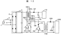
図12は、本発明の第8の実施形態による単方向DC−DCコンバータの主回路構成図であり、本実施形態も昇降圧形のソフトスイッチング単方向DC−DCコンバータである。図12において、図11までと同一の構成要素には同一符号を付し、重複説明は避ける。
図13は、本発明の第9の実施形態による単方向DC−DCコンバータの主回路構成図であり、本実施形態も昇降圧形のソフトスイッチング単方向DC−DCコンバータである。図13において、図12までと同一の構成要素には同一符号を付し、重複説明は避ける。
図14は、本発明の第10の実施形態による単方向DC−DCコンバータの主回路構成図であり、フォワードトランスとフライバックトランスを使ったソフトスイッチング単方向DC−DCコンバータを示している。図14において、図13と同一の構成要素には同じ符号を付し、重複説明は避ける。
図15は、本発明の第11の実施形態による単方向DC−DCコンバータの主回路構成図であり、フォワードトランスを使ったソフトスイッチング単方向DC−DCコンバータを示している。図15において、図14と同一の構成要素には同じ符号が付してある。
図16は、本発明の第12の実施形態による単方向DC−DCコンバータの主回路構成図であり、フライバックトランスを使ったソフトスイッチングDC−DCコンバータを示している。図16において、図8と同一の構成要素には同じ符号が付してある。
図17は、本発明の第13の実施形態による単方向DC−DCコンバータの主回路構成図であり、フライバックトランスを使ったソフトスイッチングDC−DCコンバータを示している。図17において、図8および図16と同一の構成要素には同じ符号が付してある。
図18は、本発明の第14の実施形態による単方向DC−DCコンバータの主回路構成図であり、フライバックトランス1102を使ったソフトスイッチングDC−DCコンバータを示している。図18において、図16及び図17と同一の構成要素には同じ符号が付してある。
図19は、本発明の第15の実施形態による単方向DC−DCコンバータの主回路構成図であり、フライバックトランス1102とフォワードトランス1301を使ったソフトスイッチングDC−DCコンバータを示している。図19において、図18と同一の構成要素には同じ符号が付してある。
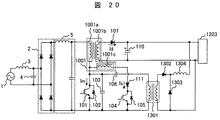
図20は、本発明の第16の実施形態による単方向DC−DCコンバータの主回路構成図であり、フライバックトランス1001とフォワードトランス1301を使い、夫々のトランスの出力が同一の負荷1203に接続されているソフトスイッチング単方向DC−DCコンバータを示している。図20において、図13と同一の構成要素には同じ符号を付してある。
図21は、本発明の第17の実施形態による単方向DC−DCコンバータの主回路構成図であり、フライバックトランス1601とフォワードトランス1301を使い、夫々のトランスの出力が同一の負荷112に接続されているソフトスイッチング単方向DC−DCコンバータを示している。図21において、図19と同一の構成要素には同じ符号を付してある。
図29は、本発明の第18の実施形態による単方向DC−DCコンバータの主回路構成図であり、これも昇降圧形のソフトスイッチング単方向DC−DCコンバータである。図29において、図1と同一の構成要素には同じ符号を付している。
図30は、本発明の第19の実施形態による単方向DC−DCコンバータの主回路構成図である。図30において、図1と同一の構成要素には同一符号を付している。
図31は、本発明の第20の実施形態による単方向DC−DCコンバータの主回路構成図である。図31において図1と同一の構成要素には同一の符号が付してある。
ここで、Lは2次側インダクタンス値、kは結合度である。また、この結合度kは、(2)式で決定される。
ここで、L’は、1次側短絡時の2次側インダクタンス値である。
Claims (3)
- 直流電源から第1のインダクタに流れる電流を断続させる第1のスイッチング素子と、
この第1のスイッチング素子に逆並列接続された第1のダイオードと、
前記第1のスイッチング素子に並列接続されたスナバコンデンサと、
前記第1のスイッチング素子をオン/オフさせ、そのデューティを制御する制御装置と、
前記第1のスイッチング素子をオンする時点を含む短期間に、逆並列接続された前記第1のダイオードに電流を流す回路手段と、
前記第1のインダクタに蓄えたエネルギーを出力側へ放出する第2のダイオードを備えた単方向DC−DCコンバータにおいて、
前記回路手段は、
直流電源に接続した前記第1のインダクタと前記第1のスイッチング素子の直列接続体と、
前記第1のインダクタと磁気的に結合した第2のインダクタと、この第2のインダクタに蓄えたエネルギーを利用して、逆並列接続された前記第1のダイオードに電流を流す第2のスイッチング素子と第3のダイオードの直列接続体と、
前記第1のスイッチング素子をオンさせる直前に、前記第2のスイッチング素子をオンさせる手段と、
前記第1のスイッチング素子の両端間電圧を平滑して出力電圧を取り出す平滑回路と、
を備え、
前記平滑回路は、前記第1のスイッチング素子の両端間に接続された第1のコンデンサと第3のインダクタの直列回路、および、前記第3のインダクタの両端間に接続された前記第2のダイオードと第2のコンデンサの直列回路とで構成され、
前記第2のコンデンサの両端間に負荷を接続したことを特徴とする単方向DC−DCコンバータ。 - 請求項1において、前記第3のインダクタは、前記第1,第2のインダクタと磁気的に結合していることを特徴とする単方向DC−DCコンバータ。
- 直流電源から第1のインダクタに流れる電流を断続させる第1のスイッチング素子と、
この第1のスイッチング素子に逆並列接続された第1のダイオードと、
前記第1のスイッチング素子に並列接続された第1のスナバコンデンサと、
前記第1のスイッチング素子をオン/オフさせ、そのデューティを制御する制御装置と、
前記第1のスイッチング素子をオンする時点を含む短期間に、逆並列接続された第1のダイオードに電流を流す回路手段と、
前記第1のインダクタに蓄えたエネルギーを出力側へ放出するダイオードを備えたDC−DCコンバータにおいて、
前記回路手段は、
直流電源から前記第1のインダクタおよび前記第1のスイッチング素子に流れる電流路内に挿入され、前記第1のインダクタと磁気的に結合した第2のインダクタと、
前記第2のインダクタの両端間に接続された第2のコンデンサと第2のスイッチング素子の直列接続体と、
前記第2のスイッチング素子に逆並列接続された第2のダイオードと、
前記第2のスイッチング素子の両端間に接続された第2のスナバコンデンサと、
前記第1のスイッチング素子をオンさせる直前に、前記第2のスイッチング素子をオフさせる手段と、
前記第2のインダクタと前記第1のスイッチング素子の直列回路の両端間電圧を平滑して出力電圧を取り出す平滑回路と、
を備え、
前記平滑回路は、前記第1のスイッチング素子と前記第1のインダクタの直列回路の両端間に接続された第1のコンデンサと第3のインダクタの直列回路、および、前記第3のインダクタの両端間に接続された第2のダイオードと第2のコンデンサの直列回路とで構成され、
前記第2のコンデンサの両端間に負荷を接続したことを特徴とする単方向DC−DCコンバータ。
Priority Applications (4)
| Application Number | Priority Date | Filing Date | Title |
|---|---|---|---|
| JP2006105256A JP4861040B2 (ja) | 2006-04-06 | 2006-04-06 | 単方向dc−dcコンバータ |
| US11/627,393 US7557546B2 (en) | 2006-04-06 | 2007-01-26 | Unidirectional DC-DC converter |
| CN200710084774A CN100588095C (zh) | 2006-04-06 | 2007-02-28 | 单向dc-dc变换器 |
| CN200910001817XA CN101453164B (zh) | 2006-04-06 | 2007-02-28 | 单向dc-dc变换器 |
Applications Claiming Priority (1)
| Application Number | Priority Date | Filing Date | Title |
|---|---|---|---|
| JP2006105256A JP4861040B2 (ja) | 2006-04-06 | 2006-04-06 | 単方向dc−dcコンバータ |
Publications (3)
| Publication Number | Publication Date |
|---|---|
| JP2007282376A JP2007282376A (ja) | 2007-10-25 |
| JP2007282376A5 JP2007282376A5 (ja) | 2009-01-08 |
| JP4861040B2 true JP4861040B2 (ja) | 2012-01-25 |
Family
ID=38575051
Family Applications (1)
| Application Number | Title | Priority Date | Filing Date |
|---|---|---|---|
| JP2006105256A Expired - Fee Related JP4861040B2 (ja) | 2006-04-06 | 2006-04-06 | 単方向dc−dcコンバータ |
Country Status (3)
| Country | Link |
|---|---|
| US (1) | US7557546B2 (ja) |
| JP (1) | JP4861040B2 (ja) |
| CN (2) | CN100588095C (ja) |
Cited By (1)
| Publication number | Priority date | Publication date | Assignee | Title |
|---|---|---|---|---|
| KR20130050081A (ko) * | 2011-11-07 | 2013-05-15 | 삼성디스플레이 주식회사 | Dc-dc 컨버터 및 이를 포함하는 발광 다이오드 구동 장치 |
Families Citing this family (27)
| Publication number | Priority date | Publication date | Assignee | Title |
|---|---|---|---|---|
| EP2001112A4 (en) * | 2006-05-15 | 2014-07-30 | Panasonic Corp | BIDIRECTIONAL POWER PERIPHERAL |
| JP4824524B2 (ja) | 2006-10-25 | 2011-11-30 | 日立アプライアンス株式会社 | 単方向dc−dcコンバータおよびその制御方法 |
| JP4643695B2 (ja) * | 2008-09-02 | 2011-03-02 | 日立コンピュータ機器株式会社 | 双方向dc−dcコンバータ及びその制御方法 |
| JP4714250B2 (ja) * | 2008-09-10 | 2011-06-29 | 株式会社日立製作所 | Dc−dcコンバータ |
| US8009444B2 (en) * | 2009-04-30 | 2011-08-30 | Hungkuang University | Boost device for voltage boosting |
| US8198882B2 (en) * | 2009-05-21 | 2012-06-12 | Hungkuang University | Power converting device with high power transformation efficiency |
| EP2443654B1 (en) * | 2009-06-16 | 2014-11-19 | ABB Technology AG | Cooling of electrical components being a transistor with an anti-parallel diode, for a convertor |
| JP5569085B2 (ja) * | 2010-03-25 | 2014-08-13 | サンケン電気株式会社 | スイッチモジュール及びそれを用いた共振型コンバータ装置 |
| KR20120140367A (ko) * | 2011-06-21 | 2012-12-31 | 삼성전자주식회사 | 아날로그/디지털 변환장치 및 이에 관한 제어 방법 |
| WO2013004019A1 (en) * | 2011-07-07 | 2013-01-10 | City University Of Hong Kong | Dc link module for reducing dc link capacitance |
| JP2013027124A (ja) * | 2011-07-20 | 2013-02-04 | Sanken Electric Co Ltd | スイッチング電源回路 |
| JP6103874B2 (ja) * | 2012-10-12 | 2017-03-29 | 株式会社日立情報通信エンジニアリング | 電源装置とその運転方法 |
| EP2747263B1 (en) * | 2012-12-18 | 2015-02-25 | Dialog Semiconductor GmbH | Back-up capacitor |
| JP5597276B1 (ja) * | 2013-04-02 | 2014-10-01 | 三菱電機株式会社 | 電源装置 |
| JP6393962B2 (ja) * | 2013-06-25 | 2018-09-26 | サンケン電気株式会社 | スイッチング電源装置 |
| US20170005563A1 (en) * | 2014-01-07 | 2017-01-05 | Arizona Board Of Regents On Behalf Of Arizona State University | Zero-Voltage Transition in Power Converters with an Auxiliary Circuit |
| CN105024534B (zh) * | 2014-04-30 | 2018-04-03 | 光宝电子(广州)有限公司 | 具功率因数修正的转换器电路 |
| EP2985898A1 (de) | 2014-08-12 | 2016-02-17 | Brusa Elektronik AG | Gleichspannungswandler mit zumindest zwei Betriebsmodi |
| CN104158402A (zh) * | 2014-08-27 | 2014-11-19 | 南京国睿新能电子有限公司 | 一种新型的升压开关电源 |
| CN104242646B (zh) * | 2014-10-17 | 2017-04-05 | 中国科学院微电子研究所 | 高频dc‑dc降压拓扑和集成芯片以及相关系统 |
| US9654112B2 (en) * | 2015-01-21 | 2017-05-16 | Panasonic Corporation | Signal inverting device, power transmission device, and negative-voltage generating circuit |
| CN104852560B (zh) * | 2015-05-15 | 2017-12-29 | 广州金升阳科技有限公司 | 开关电源中应力平衡的优化方法及适用该方法的开关电源 |
| JP6747046B2 (ja) * | 2016-05-12 | 2020-08-26 | 富士電機株式会社 | 昇圧チョッパ回路 |
| DE102016220354A1 (de) * | 2016-10-18 | 2018-04-19 | Robert Bosch Gmbh | Gleichspannungswandler und Verfahren zum Betrieb eines Gleichspannungswandlers |
| CN108092371B (zh) * | 2016-11-15 | 2020-04-03 | 华为技术有限公司 | 充放电装置 |
| US10749428B1 (en) | 2019-04-22 | 2020-08-18 | Hamilton Sunstrand Corporation | DC to DC converter with sequentially switched LC snubber and regenerative circuit |
| CN112204864A (zh) * | 2019-08-29 | 2021-01-08 | 深圳市大疆创新科技有限公司 | 驱动电路、驱动电路板与驱动器 |
Family Cites Families (15)
| Publication number | Priority date | Publication date | Assignee | Title |
|---|---|---|---|---|
| US5066900A (en) * | 1989-11-14 | 1991-11-19 | Computer Products, Inc. | Dc/dc converter switching at zero voltage |
| KR0153863B1 (ko) * | 1995-12-28 | 1998-12-15 | 김광호 | 멀티 출력 스위칭 레귤레이터 |
| US6018469A (en) * | 1997-02-05 | 2000-01-25 | Computer Products, Inc. | Low cost high efficiency power converter |
| DE69805378T2 (de) * | 1997-03-12 | 2002-11-28 | Koninkl Philips Electronics Nv | Wandler, netzteil und batterieladegerät |
| JP3427891B2 (ja) * | 2000-04-17 | 2003-07-22 | サンケン電気株式会社 | Dc−dcコンバータ |
| CN1133263C (zh) * | 2000-05-17 | 2003-12-31 | 艾默生网络能源有限公司 | 升压及降压变换软开关拓扑电路 |
| JP3578113B2 (ja) * | 2001-05-29 | 2004-10-20 | 株式会社村田製作所 | スイッチング電源装置 |
| JP3475943B2 (ja) * | 2001-06-29 | 2003-12-10 | サンケン電気株式会社 | スイッチング電源装置 |
| JP3528921B2 (ja) * | 2001-08-29 | 2004-05-24 | サンケン電気株式会社 | スイッチング電源装置 |
| JP3528920B2 (ja) * | 2001-08-29 | 2004-05-24 | サンケン電気株式会社 | スイッチング電源装置 |
| JP4085234B2 (ja) * | 2001-09-28 | 2008-05-14 | サンケン電気株式会社 | スイッチング電源装置 |
| JP2003189602A (ja) * | 2001-12-17 | 2003-07-04 | Murata Mfg Co Ltd | Dc−dcコンバータおよびそれを用いた電子装置 |
| JP4017490B2 (ja) | 2002-10-02 | 2007-12-05 | 株式会社デンソー | Dc/dcコンバータ |
| JP4534223B2 (ja) | 2004-04-30 | 2010-09-01 | ミネベア株式会社 | Dc−dcコンバータ |
| JP2006223008A (ja) * | 2005-02-08 | 2006-08-24 | Hitachi Ltd | Dc−dcコンバータ |
-
2006
- 2006-04-06 JP JP2006105256A patent/JP4861040B2/ja not_active Expired - Fee Related
-
2007
- 2007-01-26 US US11/627,393 patent/US7557546B2/en not_active Expired - Fee Related
- 2007-02-28 CN CN200710084774A patent/CN100588095C/zh not_active Expired - Fee Related
- 2007-02-28 CN CN200910001817XA patent/CN101453164B/zh not_active Expired - Fee Related
Cited By (2)
| Publication number | Priority date | Publication date | Assignee | Title |
|---|---|---|---|---|
| KR20130050081A (ko) * | 2011-11-07 | 2013-05-15 | 삼성디스플레이 주식회사 | Dc-dc 컨버터 및 이를 포함하는 발광 다이오드 구동 장치 |
| KR101876455B1 (ko) * | 2011-11-07 | 2018-07-11 | 삼성디스플레이 주식회사 | Dc-dc 컨버터 및 이를 포함하는 발광 다이오드 구동 장치 |
Also Published As
| Publication number | Publication date |
|---|---|
| CN101453164A (zh) | 2009-06-10 |
| CN101051789A (zh) | 2007-10-10 |
| CN100588095C (zh) | 2010-02-03 |
| US20070236966A1 (en) | 2007-10-11 |
| CN101453164B (zh) | 2011-07-06 |
| US7557546B2 (en) | 2009-07-07 |
| JP2007282376A (ja) | 2007-10-25 |
Similar Documents
| Publication | Publication Date | Title |
|---|---|---|
| JP4861040B2 (ja) | 単方向dc−dcコンバータ | |
| JP4824524B2 (ja) | 単方向dc−dcコンバータおよびその制御方法 | |
| Steigerwald et al. | A comparison of high-power DC-DC soft-switched converter topologies | |
| US7924579B2 (en) | Fly-forward converter power supply | |
| CN103580493B (zh) | 高功率变换器架构 | |
| US7551462B2 (en) | Soft switching DC-DC converter including a buck converter and a boost converter sharing a common transformer | |
| CN103580492B (zh) | 高功率变换器架构 | |
| US7405955B2 (en) | Switching power supply unit and voltage converting method | |
| CN109586575B (zh) | 虚拟参数高压侧mosfet驱动器 | |
| JP5585408B2 (ja) | スイッチング電源装置 | |
| Li et al. | A high-switching-frequency flyback converter in resonant mode | |
| US8064228B2 (en) | Power supply apparatus with current-sharing function | |
| US20140334194A1 (en) | Resonant Transition Controlled Flyback | |
| JP2014171310A (ja) | 共振型dc/dcコンバータ及び共振型dc/dcコンバータ装置 | |
| KR101245520B1 (ko) | 대칭형 양방향 공진형 컨버터 | |
| JP4446473B2 (ja) | Dc−dcコンバータ | |
| US5920473A (en) | Dc-to-Dc power converter with integrated magnetic power transformer | |
| US5959856A (en) | DC-to-DC power converter | |
| KR101285295B1 (ko) | 부스트 직류-직류 컨버터 | |
| KR20160101808A (ko) | 풀브리지 dc-dc 컨버터 | |
| KR101813778B1 (ko) | 하이브리드 방식 led 전원장치 | |
| KR101721321B1 (ko) | 하이브리드 방식 led 전원장치 | |
| JP2515640B2 (ja) | スイッチング電源回路 | |
| KR100889738B1 (ko) | 입출력 결합인덕터를 이용한 승강압형 능동 클램프직류-직류 컨버터 | |
| Choragudi | Analysis and Design of Pulse-Width Modulated Two-Switch Forward DC-DC Converter for Universal Laptop Adapter |
Legal Events
| Date | Code | Title | Description |
|---|---|---|---|
| A521 | Request for written amendment filed |
Free format text: JAPANESE INTERMEDIATE CODE: A523 Effective date: 20081114 |
|
| A621 | Written request for application examination |
Free format text: JAPANESE INTERMEDIATE CODE: A621 Effective date: 20081114 |
|
| A977 | Report on retrieval |
Free format text: JAPANESE INTERMEDIATE CODE: A971007 Effective date: 20110303 |
|
| A131 | Notification of reasons for refusal |
Free format text: JAPANESE INTERMEDIATE CODE: A131 Effective date: 20110315 |
|
| A521 | Request for written amendment filed |
Free format text: JAPANESE INTERMEDIATE CODE: A523 Effective date: 20110824 |
|
| TRDD | Decision of grant or rejection written | ||
| A01 | Written decision to grant a patent or to grant a registration (utility model) |
Free format text: JAPANESE INTERMEDIATE CODE: A01 Effective date: 20111101 |
|
| A01 | Written decision to grant a patent or to grant a registration (utility model) |
Free format text: JAPANESE INTERMEDIATE CODE: A01 |
|
| A61 | First payment of annual fees (during grant procedure) |
Free format text: JAPANESE INTERMEDIATE CODE: A61 Effective date: 20111104 |
|
| R150 | Certificate of patent or registration of utility model |
Free format text: JAPANESE INTERMEDIATE CODE: R150 |
|
| FPAY | Renewal fee payment (event date is renewal date of database) |
Free format text: PAYMENT UNTIL: 20141111 Year of fee payment: 3 |
|
| LAPS | Cancellation because of no payment of annual fees |